1
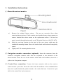
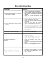
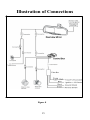
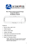
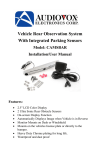
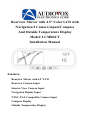
Rearview Mirror with 4.5" Color LCD with
Navigation/2 Camera inputs/Compass
And Outside Temperature Display
Model: LCMR6CT
Installation Manual
Features:
Rearview Mirror with 4.5” LCD
Rearview Camera Input
Interior View Camera Input
Navigation Display Input
NTSC /PAL Compatible Camera Input
Compass Display
Outside Temperature Display
Cautions!
The product is intended to assist in safe driving and to allow the driver to
have a broader rearview while the vehicle is in reverse. You, as the driver,
are solely responsible for the safe operation of your vehicle and the safety
of your passengers according to the country and their local traffic
regulations. Do not use any features of this system to the extent it distracts
you from safe driving. Your first priority while driving should always be
the safe operation of your vehicle. Audiovox Electronics Corporation
cannot accept any responsibility whatsoever for accidents resulting from
failure to observe these precautions or safety instructions.
1. This product utilizes high voltage. Any unauthorized modifications
or damage to the products may result in electrical shock. Handle
all components with care. Inspect regularly for damage to
components and cabling.
2. You shall be responsible to ensure that the installation of this
product does not void or affect the vehicle manufacturer’s
warranty. Audiovox Electronics Corporation, or its branches are
not liable in full or in part for improper installation resulting in
loss or damage to your property, or for voiding all or part of the
vehicle manufacturer’s warranty.
3. Do not apply excessive force to any of the components contained
within this kit. Excessive force used before, during or after
installation that results in a damaged or non-functional part shall
void all warranties.
4. Please follow the procedure from this installation manual.
Improper installation or modification of this product shall void all
warranties.
1
TABLE OF CONTENTS
Cautions!
1
Preface
3
Packing list
3
1.Installation Instructions
4
2.Signal Inputs
7
3.Controls and Indicators
9
Specifications
12
Maintenance
13
Troubleshooting
14
Illustration of connections
15
2
Preface
This replacement mirror /monitor can display up to 3 different video
inputs. The inputs are Navigation, Rear observation camera and Interior
observation camera.
Not all rearview mirrors attach to the vehicle with the same style mount.
Please consult the application guide for the appropriate mounting bracket
for your vehicle or call Tech Service at 800-225-6074.
Packing list
The Rear view mirror Model LCMR6CT consists of the following items:
1. Rear View Mirror-1
2. Camera Cable-2
3. Control Box-1
4. Filter Box -1
5. Control Box Monitor Cable -1
6. Compass sensor –1
7. Temperature sensor -1
8. Tapping Screw –3
9. Connector-1
10. Wire cover -2
11. Double side adhesive tape –1
12. Compass &Temperature Monitor Cable –1
3
1. Installation Instructions
(1) Mount the mirror/monitor
a)
Remove the original factory mirror.
(Do not use excessive force when
removing factory mirror.) Check to make sure that the factory mirror mount you
remove matches the mirror mount on the replacement mirror. If it does not
match, consult the application guide or call Technical Service at 800-225-6074.
b)
Slide the receiving bracket on the back of the new mirror stalk onto the
windshield mounting button. Move the bracket back and forth until completely
seated.
c)
Tightly the T-20 mounting bracket screw.
(2) Navigation monitor connection (optional): Insert the connector from the
Audiovox navigation monitor cable into the receptacle at the backside of the
mirror/monitor. Route the rest of the monitor cable under the headliner, down the A
pillar to the Navigation computer.
(3) Control box connection: Connect the 8-pin extension cable to the rearview
mirror/monitor 8 pin cable. Route the cable under the headliner of the windshield then
down the A pillar behind the plastic shroud to the under dash area. Connect the 8-pin
cable to the control box 8 pin connector.
4
(4) Installing the Temperature Sensor.
a) Select a suitable location for the Temperature sensor outside of the vehicle. The
location should be in the nose area of the vehicle, between the front of the radiator
and front bumper where there will be airflow. Keep the sensor as low as possible,
and as far away from the radiator as possible.
b) Use the supplied screw to secure the temperature sensor to the selected location.
c) Route the temperature sensor cable towards the firewall, securing the cable
where it doesn't interfere with moving parts.
d) Pass the terminals thought a grommet into the passenger compartment,
e) Route the wires up to and behind the A pillar, then under the headliner towards
the Rearview mirror.
Figure 2
f) Insert the terminals into the two-pin connector until a snap is heard.
g) Connect the 6-pin Temperature/Compass Y cable to the rearview
mirror/monitor cable.
h) Connect the 2-pin connector from the sensor to the mating end of the
Temperature/ Compass Y cable.
(5) Installing the Compass sensor:
a ). Select a suitable mounting location for the compass sensor. The sensor must
be mounted horizontally and with the Arrow pointing towards the front of the
vehicle. Do not mount near a speaker or magnetic source. Under the dash top
panel is a recommended location.
5
b ) Secure the Compass sensor using the screw provide or double sided adhesive tape to the
selected location with the head of the compass sensor arrowhead facing forward.
c ) Route the Compass cable up the A pillar and connect the 5 pin Compass Sensor cable to
the mating 5 pin connector of the Temperature/ Compass Y cable.
d ) Tuck the connectors under the head liner.
Figure 3
Note: Compass must be calibrated before use.
How to Calibrate the Compass Direction
A. Ensure the Compass Sensor has been securely mounted.
B. Position the vehicle so that the front of the vehicle faces North.
C. Press the Calibration Switch located on the right rear side of the
mirror to the “IN” position.
D. Drive the vehicle in one or more complete circles.
WARNING: Calibration must last at least 10 seconds.
E. Press the Calibration Switch again, returning the switch to the
“OUT” position. Now the mirror will display the compass direction
accurately.
(6) Installing the Mirror Cable Cover
a)
Remove the adhesive tape on the base of the cable cover, and stick it to the windshield
next to the mirror’s mounting bracket
b)
Put the mirror extension cables on the wire cover’s base, and then install the top cover
into the base to cover both cables.
(7) Electrical Connections: Connect the 4 Wires from the filter box as follows:
a)
Red wire -12- volt constant (+12 volts)
b)
c)
Blue wire -12-volt ignition (12 volts with ignition on switch on)
Black wire - Chassis ground (negative)
d)
Green wire - Reverse light switch (12 volt when vehicle is in the reverse gear)
6
WARNING: Observe polarity when connecting the wires.
Control BOX
To Control BOX
Filter BOX
Cam Button
Selector Switch
To Rearview Camera
Red (+12V)
Blue (Ignition)
Black (GND)
Green (Reverse)
To Interior Camera
To Mirror Assembly
To Filter BOX
Figure 4
2. Signal Inputs
The signal input connections for the system include:
(1) Rear Camera: Plug the RJ 11 camera cable end into the control box
AVin-1 location, route the cable to the rear camera and plug the 4-pin
connector into camera 4 pin connector. Users can see the rearview camera
image when the car is shifted into reverse.
(2)
Interior Camera: Plug the RJ 11 camera cable end into the control box
AVin-2, Users can see the interior camera image when the “CAM” button is
pressed.
(3) Compass Sensor: Connected directly to mirror.
(4) Temperature Sensor: Connected directly to mirror.
(5) Navigation: The navigation signal is supplied via the monitor cable
plugged directly into the rear of the mirror.
7
(6) Navigation Image (optional Navigation System required)
The Navigation Image is the default mode, and will only be overridden
when the vehicle gear selector is moved into reverse, or if the CAM button
on the mirror is pressed.
Some operators may find that leaving the Navigation Image on the LCD
monitor at all times becomes a distraction while operating their motor
vehicle. For the convenience of those operators, a ‘Display Timer Slide
Control Switch’ has been added to the mirror.
A. When the Slide Control Switch is moved to the far right end position,
the Navigation image will remain on at all times.
B. When the Slide Control Switch is moved to the far left end position,
the Navigation image will remain off at all times.
C. Positioning the Slide Control Switch anywhere in the center area will
automatically enable an internal timer. The timer is adjustable between 10
Seconds (further left) to 3 minutes (further right).
D. When the Navigation System is in guidance mode, every time a turnby-turn voice guidance command is received, the Navigation image will
automatically turn on and remain on for the pre-selected time set by the
Slide Switch. After the pre-set time has expired, the Navigation display will
turn off and remain off until the next voice command is received.
HINT 1: When entering a new address into the Navigation Address Book, it will
be easier to move the Slide Control Switch all the way to the right to keep the
LCD display on until the address has been completed.
HINT 2: When in Timed Display Mode, you can press the “+” or “-“ button on the
mirror to turn the Navigation image on for the full extent of the pre-set time.
8
Figure 5
3. Controls and Indicators
Figure 3 shows the function controls of the rear view mirror.
A: 4.5" LCD Panel
B: Rearview Mirror Glass
C: “+”Button (optional Navigation System required)
Incrementally increase volume level of the navigation voice command when
pressed.
Note: Will only operate when the Navigation System remote control is
removed from the cradle.
D: “CAM” Button
-
If you have installed an optional interior view camera, pressing the CAM
button will display the image from the interior view camera on the LCD
panel.
-
If you do not have an interior view camera installed, but have installed a
back up camera, then pressing the CAM button will display the image
from the back up camera on the LCD panel.
-
Either image will be displayed for as long as the CAM button is held on.
As soon as the button is released, the LCD will automatically switch back
to the original setting.
9
E: “MAP” Button (optional Navigation System required)
Each time the “MAP” button is pressed, the navigation display will toggle
between Map, Icon only and split screen while in navigation mode.
Note: Will only operate when the Navigation System remote control is
removed from the cradle.
F: “-” Button (optional Navigation System required)
Incrementally decrease volume level of the navigation voice command when
pressed.
Note: Will only operate when the Navigation System remote control is
removed from the cradle.
G: Internal Speaker
H: LCD Brightness Control
I: Internal Infra-RED Receiver for use with Navigation System Remote Control.
J: Power LED (Red when Power is on)
K: Display Timer Slide Control Switch: (optional Navigation System required)
Refer to # 3 below for detailed operation notes.
L: “T/C” Button
The temperature/compass button switches between Fahrenheit and Celsius
settings and also turns the display on or off. Press once to turn on the
continuous temperature (F)/compass display. Press again to switch the
temperature display to Celsius. Next press will turn off the
Temperaure/Compass display
M: Internal Speaker Switch (optional Navigation System required): Use to turn
the internal Speaker on/off. Remove the L-Cover at the left end of the mirror
using a Mini screwdriver (see Figure4), to gain access to the small switch inside.
To disable the internal speaker, set the switch to the off position (See Figure5).
Set the switch to the ON position to enable the internal speaker (see Figure5).
10
Figure 6
Figure 7
N: Calibration Switch: Used to calibrate the compass display.
11
Specifications
General
Power Supply
12VDC
Power Consumption
<12W
Current Draw
<800mA
Video Input
1Vp-p/ 75 Impedance
Audio Input
<=1V
Audio Power Output
0.5W × 1 (16Ω)
Operating Temperature Range
0 degrees C to 50 degrees C
Display System
Screen
4.5” TFT Color LCD
Brightness
400 cd/
Contrast Ratio
Backlight Life
150 : 1
10000 hours
Resolution
960×234
Video Format
PAL/NTSC auto detect
Display Format
16 : 9
Navigation input
RGB
12
Maintenance
Though your Rearview mirror requires little care, you can still maintain
its condition and performance by following the procedures below.
Keep your system away from excessive moisture, extreme heat
or cold, and magnetic fields.
Keep liquids away from the display and mirror.
To avoid damage, do not place external devices or other objects
on the top of the mirror.
Occasionally wipe the rearview mirror set with a soft, damp
cloth.
Occasionally clean the surface of the mirror with a soft cloth
moistened with water or window cleaner.
13
Troubleshooting
Symptoms
Solutions
1.
2.
The ON/OFF signal light <E> is not on
after the car is started?
3.
1.
2.
3.
No video signal appears while reversing
the car?
4.
Check the installation-wiring diagram.
Ensure that the parallel red and black
line from the control box is connected
properly.
Check for 12 volts on the blue wire
while the ignition on.
Check the rearview Camera lens.
Check the rearview Camera wiring and
connection.
Check the cable from the rearview
mirror is connected to the control box.
Check out the wire connection (to find
out whether the system’s reverse wire
cable is connected to the reverse switch
gear of the car)
Video image is not sharp enough?
Clean the lens of the camera.
1.
2.
Heading Information is not
accurate?
3.
4.
5.
Temperature/Compass display does not
Change when T/C button is pressed
1.
14
Calibrate the system.
Check The Compass Sensor close to
speaker or other magnetic devices.
Check The Compass Sensor close to
Steal part.
Check the Compass Sensor on horizontal
plane.
Check the Compass Heading direction.
Calibration button is pressed in. Press
and release calibration button to the
“OUT” position.
Illustration of Connections
Figure 8
15
© 2006 Audiovox Electronics Corp., 150 Marcus Blvd., Hauppauge, N.Y. 11788
128-7737
16