1
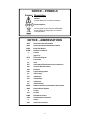
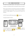
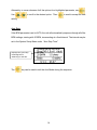
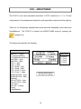
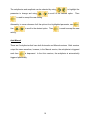
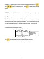
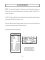
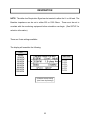
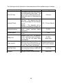
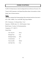
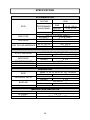
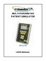
MULTI-PARAMETER
PATIENT SIMULATOR
PS-2110
USER MANUAL
BC BIOMEDICAL
PS-2110
TABLE OF CONTENTS
WARNINGS, CAUTIONS, NOTICES .............................................................................. ii
DESCRIPTION ............................................................................................................... 1
LAYOUT ......................................................................................................................... 5
ECG--NORMAL SINUS RHYTHM................................................................................ 13
ECG--ARRHYTHMIAS ................................................................................................. 15
ECG--PERFORMANCE ............................................................................................... 19
BLOOD PRESSURE .................................................................................................... 21
RESPIRATION ............................................................................................................. 23
TEMPERATURE .......................................................................................................... 25
SETUP ......................................................................................................................... 26
POWER UP SETTINGS .............................................................................................. 29
SpO2 (OPTION) ........................................................................................................... 31
OUTPUT CONNECTIONS ........................................................................................... 32
MANUAL REVISIONS .................................................................................................. 33
LIMITED WARRANTY ................................................................................................. 33
SPECIFICATIONS ....................................................................................................... 34
NOTES ......................................................................................................................... 36
This User Manual covers the following units:
PS-2110
i
WARNING - USERS
The PS-2110 is for use by skilled technical
personnel only.
WARNING - USE
The PS-2110 is intended for testing only and
should never be used in diagnostics, treatment
or any other capacity where it would come in
contact with a patient.
WARNING - CONNECTIONS
All connections to patients must be removed
before connecting the DUT to the PS-2110. A
serious hazard may occur if the patient is
connected when testing with the PS-2110.
CAUTION - MODIFICATIONS
The PS-2110 is intended for use within the
published specifications. Any application
beyond these specifications or any unauthorized
user modifications may result in hazards or
improper operation.
CAUTION - SERVICE
The PS-2110 is intended to be serviced only by
authorized service personnel. Troubleshooting
and service procedures should only be
performed by qualified technical personnel.
ii
CAUTION - INSPECTION
The PS-2110 should be inspected before each
use for obvious signs of abuse or wear. The PS2110 should not be used and should be serviced
if any parts are in question.
CAUTION - CLEANING
Do not immerse. The PS-2110 should be cleaned
by wiping gently with a damp, lint-free cloth. A
mild detergent can be used if desired.
CAUTION - LIQUIDS
Do not submerge or spill liquids on the PS-2110.
Do not operate the PS-2110 if it may have been
exposed to fluid.
CAUTION - ENVIRONMENT
Exposure to environmental conditions outside
the specifications can adversely affect the
performance of the PS-2110. Allow the PS-2110
to acclimate to specified conditions for at least
30 minutes before attempting to operate it.
iii
NOTICE – CE
The PS-2000 Series Meters bear the
mark
Based on the following testing standards:
ELECTROMAGNETIC COMPATIBILITY DIRECTIVE
EMC – Directive 89/336/EEC as amended by 92/31/EEC and 93/68/EEC
& Directive 91/263/EEC[TTE/SES]
EN 61326-1:1997 + A1:1998 + A2:2001 + A3:2003
“Electrical equipment for measurement, control and
laboratory use – EMC requirements”
This equipment has been type tested by an independent, accredited testing laboratory
and compliance was demonstrated to the above standard to the extent applicable.
EMISSIONS
Radiated Emissions
EN 61326:1997 Annex C
IMMUNITY– CLASS C
EN 61000-4-2:1995
EN 61000-4-3:2006
Electrostatic Discharge
Radiated Electric Field Immunity
LOW VOLTAGE DIRECTIVE
EC – Directive 73/23/EC
EN 61010-1:2001
“Safety requirements for electrical equipment for measurement, control, and
laboratory use – General requirements”
This equipment has been type tested and compliance was demonstrated
to the above standard to the extent applicable.
iv
NOTICE – SYMBOLS
Symbol Description
Caution
(Consult Manual for Further Information)
Center Negative
Per European Council Directive 2002/95/EC,
do not dispose of this product as unsorted
municipal waste.
NOTICE – ABBREVIATIONS
AHA
American Heart Association
ANSI
American National Standards Institute
BPM
Beats Per Minute
BrPM
Breaths Per Minute
C
Celsius
°
degree(s)
ECG
F
Electrocardiogram
Fahrenheit
Hz
hertz
IEC
International Electrotechnical Commission
IBP
Invasive Blood Pressure
kHz
kilohertz
LED
Light Emitting Diode
µV
microvolt(s)
mA
milliamp(s)
mm
millimeter(s)
mV
millivolt(s)
ms
millisecond(s)
NEDA
NSR
National Electronic Distributors Association
Normal Sinus Rhythm
Ω
ohm(s)
Lbs
pounds
RMS
Root Mean Square
USA
United States of America
V
VDC
Volt(s)
Volts Direct Current
v
NOTICE – DISCLAIMER
BC GROUP INTERNATIONAL, INC. WILL NOT BE RESPONSIBLE
FOR ANY INJURIES SUSTAINED DUE TO UNAUTHORIZED
EQUIPMENT MODIFICATIONS OR APPLICATION OF EQUIPMENT
OUTSIDE OF THE PUBLISHED INTENDED USE AND
SPECIFICATIONS.
NOTICE – DISCLAIMER
BC GROUP INTERNATIONAL, INC. RESERVES THE RIGHT TO
MAKE CHANGES TO ITS PRODUCTS OR SPECIFICATIONS AT
ANY TIME, WITHOUT NOTICE, IN ORDER TO IMPROVE THE
DESIGN OR PERFORMANCE AND TO SUPPLY THE BEST
POSSIBLE PRODUCT. THE INFORMATION IN THIS MANUAL HAS
BEEN CAREFULLY CHECKED AND IS BELIEVED TO BE
ACCURATE. HOWEVER, NO RESPONSIBILITY IS ASSUMED FOR
INACCURACIES.
NOTICE – CONTACT INFORMATION
BC BIOMEDICAL
BC GROUP INTERNATIONAL, INC.
3081 ELM POINT INDUSTRIAL DRIVE
ST. CHARLES, MO 63301
USA
1-800-242-8428
1-314-638-3800
www.bcgroupintl.com
[email protected]
PS-2110 User Manual
www.bcgroupintl.com
10/12
Copyright © 2012
Made in the USA
Rev 05
vi
BC BIOMEDICAL
PS-2110
PATIENT SIMULATOR
The Model PS-2110 is a Microprocessor based Patient Simulator. It provides ECG, Blood
Pressure, Respiration and Temperature Simulation. There are 12 arrhythmias, a
pacemaker rhythm, a Fetal/Maternal rhythm, seven waveforms with constant QRS duration
and 12 machine performance testing waveforms.
The PS-2110 makes viewing and selecting the desired waveforms and parameters quick
and intuitive, with all operational information being available at one time on a cursor-based
graphic display, allowing for easy maneuvering through parameters and scrolling through
available options.
The following are highlights of some of the main features:
SIMPLE TO OPERATE
NO CODES TO REMEMBER OR ENTER
BACKLIT GRAPHICS DISPLAY WITH SIMULTANEOUS DETAILED STATUS
OF PARAMETERS AND SCROLLING CONTROL OF OPTIONS
DROP DOWN CHOICE SCREENS LIST ALL OPTIONS FOR PARAMETERS
SPECIAL POWER UP FEATURE ALLOWS THE USER TO CHOOSE TO USE
DEFAULT, LAST OR CUSTOM SETTINGS
AUTO SEQUENCES FOR BPM, STATIC-PRESSURE LEVELS AND
PERFORMANCE
10 UNIVERSAL PATIENT LEAD CONNECTORS
9 VOLT BATTERY POWER
% BATTERY LIFE DISPLAY
LOW BATTERY INDICATOR
AVAILABLE BATTERY ELIMINATOR
FLASH PROGRAMMABLE FOR UPGRADES
ECG FUNCTIONS
The unit can produce a wide variety of ECG simulations. The user simply selects the
parameters that match the desired output.
RATE:
30, 60, 80, 120, 180, 240, 300 BPM
AMPLITUDE:
0.5, 1.0, 1.5, 2.0 mV (Lead II)
AUTOMATIC MODE
1
PACEMAKER FUNCTION
A pacemaker waveform may be simulated.
WAVEFORM:
ASYNCHRONOUS
PULSE HEIGHT:
1.0 mV
PULSE WIDTH:
1.0 ms
FETAL/MATERNAL
A combination of fetal and maternal ECG waveforms may be simulated.
FETAL HEARTRATE:
120 BPM
ARRHYTHMIA FUNCTIONS
The unit can simulate 12 different arrhythmias. Where applicable, both manual and
automatic triggering of the waveform is available.
12 DIFFERENT ARRHYTHMIAS
MANUAL AND AUTOMATIC TRIGGERING
ECG-PERFORMANCE FUNCTIONS
The unit will generate Sine, Square and Triangular waveforms with adjustable
amplitudes for performance testing. A special Automatic mode is available to auto
sequence through the entire range of waveforms.
SINE:
0.1, 0.5, 5, 10, 40, 50, 60, 100 Hz
SQUARE:
0.125, 2.000 Hz
TRIANGLE:
2.000 Hz
AMPLITUDE:
0.5, 1.0, 1.5, 2.0 mV (Lead II)
AUTOMATIC MODE
2
RESPIRATION
Respiration is simulated at 8 different rates plus apnea, with the ability to select from 2
Baseline Impedances, the Lead in which it will appear, and the Delta Ohms (amplitude) of
the signal.
RATE:
15, 20, 30, 40, 60, 80, 100, 120 BrPM
BASELINE IMPEDANCE:
500, 1000 Ω
LEAD:
LA or LL
DELTA IMPEDANCE:
0.1, 0.2, 0.5, 1.0, 2.0, 3.0 Ω
APNEA: CONTINUOUS (0 BrPM)
BLOOD PRESSURE
Both static and dynamic invasive pressures are simulated. In the static mode the BP
output is fixed at the selected level or sequenced through the list using the Automatic
mode selection. In the Dynamic mode the selected waveform is synchronized with the
ECG and provides a continuous output.
STATIC:
0, 20, 40, 80, 100, 200, 250, 300 mmHg
AUTOMATIC STATIC PRESSURE MODE
6 DYNAMIC WAVEFORMS
SENSITIVITY:
5 and 40 µV/V/mmHg
TEMPERATURE
The unit will simulate three temperatures. This is done by providing the necessary ohmic
levels for both the YSI 400 and 700 Series thermistors.
YSI SERIES 400 and 700 SIMULATION
SELECTIONS:
30, 37, 40 °C (86.0, 98.6, 104.0 °F)
LEAD TEST FUNCTION
The unit provides a set of test terminals to quick check leads. It will determine if a lead has
less than 1000 Ohms resistance.
3
SPO2 SIMULATION (Option)
When used with the MSP-2100 external module and FingerSim family of SpO2 finger
simulators, the system will provide a pulse synchronized SpO2 output for all NSR rates.
RATE:
30, 60, 80, 120, 180, 240, 300 BPM
SpO2 OUTPUT:
80, 90, 97 %
4
LAYOUT
This section looks at the layout of a PS-2110 and gives descriptions of the elements that
are present.
Lead Test
Connections
LCD Graphical
Display:
Shows Parameters
for ECG,
Respiration,
Blood Pressure
and
Temperature
10 Universal
Patient Lead
Connectors:
RA R
LA
L
RL(-) N
LL
F
V1 C1
V2 C2
V3 C3
V4 C4
V5 C5
V6 C6
7 Light Touch Keys
for Selecting
Parameters and
Settings:
LEFT and RIGHT
Curved Arrows for
Moving through
Parameters
UP and DOWN
Arrows for Scrolling
through Options
ENTER for
Selecting Option
CHOICES for
Displaying
Submenu of All
Options for a Given
Parameter
QUIT for Returning
to Previous Status
6-Pin Mini-DIN
Plug Connector
for Blood
Pressure Cable
8-Pin Mini-DIN
Plug Connector
for Temperature
Cable
7-Pin Mini-DIN
Plug Connector
for Aux
Functions
Battery
Eliminator jack
Power Key
for Turning Unit
On and Off
4 Light Touch Keys for
Category Selection:
Normal Sinus Rhythm
Arrhythmias
Performance
Setup
5
Back Light Key for
turning on and off
the backlight
General Operation
The unit is controlled by 13 light touch keys. They allow the user to move around within the
displayed parameters, select the desired options, choose a specific category and control
the setup and power for the unit. When a key is depressed there is an audio click when it
is accepted, or a razz tone if the key is invalid.
A graphics LCD display provides the user with information about the current status of the
ECG, Respiration, Blood Pressure and Temperature settings. The
keys
move the block cursor through the displayed information; highlighting the parameter
available for selection. The
parameter.
keys change the options for the highlighted
The cursor begins flashing if the parameter has been changed.
key selects the changed option. The
The
key returns to the previous state,
without any changes being made.
To make option selection even easier and to make memorizing and using codes
unnecessary, the
key will bring up a screen that displays all the options for the
selected parameter. The
and
keys can then be used to quickly
scroll through the available options and select the desired setting.
Three category keys allow for quick setting of output waveforms. The
,
keys move the display directly to the selected category. The
keys
can
then
be
used
to
scroll
settings.
6
through
and
select
and
or
the
desired
The
key opens a screen that allows the user to select the unit’s general output
settings, as well as setup for the system.
Category Keys
The category,
The
and
keys can be used to select ECG waveforms.
key enters the NSR category and gives access to the seven BPM (Beats Per
Minute) settings with constant QRS duration.
The
key enters the arrhythmia category and changes the first line in the display to
the first arrhythmia choice.
The
key enters the machine performance testing category and changes the first
line in the display to the first performance waveform choice.
Power Key
The
key turns the unit on and off. To turn off the unit, the key must be held for 1
second.
7
Backlight
The Graphic LCD display may be viewed with or without the backlight. Depressing any key
will activate the backlight. However, since the backlight will drain the battery if left on, it will
automatically shut off after a few seconds when running on battery power. (Note: This time
is selectable in the System Setup screen).
The intensity of the backlight can be adjusted in the System Setup screen to conserve
battery life.
The
key is provided to toggle the backlight on or off at any time.
NOTE: The backlight parameter in the System Setup screen may be set to Off, 1-30 sec
Timed or Manual.
ECG Waveforms
The microprocessor has stored in its memory all of the digitalized waveforms. It sends the
individual lead waveforms to D/A converters, which generate accurate analog
representations. The waveforms are then sent through resistor networks, developing the
appropriate signals on the output terminals.
8
Respiration
Respiration waveforms are provided that have adjustable rates from 15 to 120 BrPM
(Breaths Per Minute) as well as an Apnea (0 BrPM) setting. The signal is generated by
a variation in the impedance in either the LL or LA lead (selectable). The amplitude is
settable from 0.5 to 3.0 ohms.
Blood Pressure
IBP pressure simulation is available through the 6-pin mini-DIN plug connector on the
right side of the unit. The circuit is totally isolated.
Temperature
There is an 8-pin mini-DIN plug connector on the right side of the unit for connection of
a Temperature cable. Temperatures are simulated for both YSI 400 and YSI 700 probe
types. There are three different temperatures selectable for each.
9
Universal Patient Lead Connectors
The 10 Universal Patent Lead Connectors allow for 12 lead ECG simulation with
independent outputs. AHA and IEC color-coded labels are located on the face of the unit
to aid in connecting the corresponding U.S. and International Patient Leads.
AHA Label
IEC Label
Description
RA
R
Right Arm
LA
L
Left Arm
RL
N
Right Leg
(reference or ground)
LL
F
Left Leg
V1
V2
V3
V4
V5
V6
C1
C2
C3
C4
C5
C6
V Leads (U.S. Canada),
also referred to as
pericardial,
precordial or
unipolar
chest
leads
Chest
Leads
(International)
High Level Output (+)
A high level ECG output signal (200 x Amplitude Setting) is available in the BP 6-Pin
mini-DIN connector.
Lead Test Terminals
There are two test terminals on the top of the unit that allow for a quick test of the
continuity of the lead cables. Connecting one end of the cable to one terminal and the
other end to the other terminal will test the cable. If the cable is OK (less than 1000
ohms), the LEAD TEST ACTIVE screen will be displayed.
10
Auto Power Off
The unit may be programmed to automatically turn off after a selected number of minutes
of no key activity to conserve the battery. (Note: This time is selectable in the System
Setup screen).
Battery
The unit utilizes two 9 Volt Alkaline Batteries in the rear battery compartment. When the
unit detects a LOW BATTERY condition (5% Battery Life), a warning window will appear
once per minute to alert the user. The
key may be used to clear this window and
continue use of the unit. If the battery is not replaced before the battery reaches a critical
level (0 % Battery Life), the unit will shut down. (The percentage of life left in the batteries
can be viewed in the System Setup screen.)
Battery Eliminator
The unit has a 2.1 mm jack for connecting a 9-Volt Battery Eliminator (Optional).
Note: The Battery Eliminator will not charge the battery.
Power Up Settings
The unit may be setup to turn on using either the factory default settings, the same settings
that it had when last turned off or a custom set of parameters as previously saved by the
user (See Power Up Settings section for details).
11
Automatic Modes
The ECG NSR Rate, ECG Performance and Static Blood Pressure Parameters all allow
for an automatic setting. In each of these, the unit will sequence through the full range of
settings automatically at a fixed rate (as selected in the Auto Step Time Parameter). When
in this mode, the time remaining in each step is displayed.
The
key may be used to manually advance to the next step. The
used to terminate the mode.
12
key is
ECG – NORMAL SINUS RHYTHM
The PS-2110 can send NSR waveforms to ECG machines in 3, 5 or 12 lead
configurations. It has independent outputs for each signal lead, referenced to the right leg.
NSR occurs when the heartbeat is normal, beating at a rate between 50 and 100 BPM with
a standard QRS waveform shape and height. The PS-2110 simulates the NSR with a
default rate of 80 BPM, amplitude of 1.0 mV on Lead II and P-R interval of 160
milliseconds.
The PS-2110 is placed into NSR mode by pressing the
category key.
The display will resemble the following:
PATIENT MODE
Adult
(80 mS QRS)*
RATE
30 BPM
60 BPM
80 BPM*
120 BPM
180 BPM
240 BPM
300 BPM
Auto
AMPLITUDE
* Indicates Default Setting
(See Power Up Settings)
The rates and amplitudes can be selected by using
parameter to change and using
0.5 mV
1.0 mV*
1.5 mV
2.0 mV
to highlight the
to scroll to the desired value. Then
is used to accept the new setting.
13
Alternately, to see a submenu of all the options for a highlighted parameter, use
Use
to scroll to the desired option. Then
.
is used to accept the new
setting.
Auto Rate
If the BPM parameter is set to AUTO, the unit will automatically sequence through all of the
BPM settings, starting with 30 BPM, incrementing at a fixed interval. The interval may be
set in the System Setup Menu under “Auto Step Time”.
Displays time (seconds)
remaining before
advancing to next rate.
The
key can be used to exit the Auto Mode during the sequence.
14
ECG – ARRHYTHMIAS
The PS-2110 can send arrhythmia waveforms to ECG machines in 3, 5 or 12 lead
configurations. It has independent outputs for each signal lead, referenced to the right leg.
There are 12 Arrhythmias available that model abnormal heartbeats, plus Paced and
Fetal/Maternal.
The PS-2110 is placed into ARRHYTHMIA mode by pressing the
category key.
The display will resemble the following:
ARRHYTHMIAS
Atrial Fib – Coarse
2nd Deg Heart Block
RT Bundle Branch Block
Atrial PAC – Auto
Atrial PAC – Man
PVC 1 – Auto
PVC 1 – Man
PVC 1 Early – Auto
PVC 1 Early – Man
PVC 1 R on T – Auto
PVC 1 R on T – Man
Multifocal PVCs – Auto
Multifocal PVCs – Man
Bigeminy
Run of 5 PVCs – Auto
Run of 5 PVCs – Man
Vent Tach
Vent Fib – Coarse
Paced
Fetal/Maternal
AMPLITUDE
0.5 mV
1.0 mV*
1.5 mV
2.0 mV
* Indicates Default Setting
(See Power Up Settings)
15
The arrhythmias and amplitude can be selected by using
parameter to change and using
to highlight the
to scroll to the desired option.
Then
is used to accept the new setting.
Alternately, to see a submenu of all the options for a highlighted parameter, use
Use
to scroll to the desired option. Then
is used to accept the new
setting.
Auto/Manual
There are 6 arrhythmias that have both Automatic and Manual versions. Both versions
output the same waveform; however, in the Manual version, the arrhythmia is triggered
each time
is depressed. In the Auto versions, the arrhythmia is automatically
triggered periodically.
16
The following is a brief description of how the PS-2110 simulates the available
Arrhythmias:
Abbreviation
Arrhythmia
Description
Atrial Fib
Atrial Fibrillation
2nd Deg Heart
Block
Second Degree Heart Block
Rt Bundle
Branch Block
Right Bundle Branch Block
Atrial PAC –
Auto
Premature Atrial Contraction
Atrial PAC –
Man
Premature Atrial Contraction
PVC 1 – Auto
Standard Type 1
Premature Ventricular Contraction
PVC 1 – Man
Standard Type 1
Premature Ventricular Contraction
PVC 1 Early Auto
Early Type 1
Premature Ventricular Contraction
PVC 1 Early Man
Early Type 1
Premature Ventricular Contraction
PVC 1 R on T
– Auto
R on T Type 1
Premature Ventricular Contraction
PVC 1 R on T
– Man
R on T Type 1
Premature Ventricular Contraction
17
Absence of P-wave and irregular P-R
interval rate
(Continuous)
80 BPM with increasing P-R interval
for four beats (160, 220, 400, 470 ms)
followed by a P wave without a QRS
(Continuous)
80 BPM with Normal P-wave and P-R
interval but wider QRS complexes
(Continuous)
NSR of 80 BPM with Periodic
Abnormal 25% early P waves
(PAC, 7 NSR)
(Continuous)
NSR of 80 BPM with Periodic
Abnormal 25% early P waves
(One-Time event)
NSR of 80 BPM with periodic left focus
premature ventricular beats with 20%
premature timing
(PVC Type 1, 9 NSR)
(Continuous)
NSR of 80 BPM with periodic left focus
premature ventricular beats with 20%
premature timing
(One-Time event)
NSR of 80 BPM with periodic left focus
premature ventricular beats with 33%
premature timing
(PVC Type 1, 9 NSR)
(Continuous)
NSR of 80 BPM with periodic left focus
premature ventricular beats with 33%
premature timing
(One-Time event)
NSR of 80 BPM with periodic left focus
premature ventricular beats with 65%
premature timing, placing R on the
previous T
(PVC Type 1, 9 NSR)
(Continuous)
NSR of 80 BPM with periodic left focus
premature ventricular beats with 65%
premature timing, placing R on the
previous T
(One-Time event)
Multifocal
PVCS – Auto
Multifocal
Premature Ventricular Contraction
Multifocal
PVCS – Man
Multifocal
Premature Ventricular Contractions
Bigeminy
Bigeminal Rhythm
Run of 5
PVCs – Auto
Run of 5 Premature Ventricular
Contractions
Run of 5
PVCs – Man
Run of 5 Premature Ventricular
Contractions
Vent Tach
Ventricular Tachycardia
Vent Fib –
Coarse
Ventricular Fibrillation
Paced
Paced Rhythm
Fetal /
Maternal
Fetal/Maternal ECG
18
NSR of 80 BPM with Type 1 and Type
2 PVCs (PVC Type 1, 2 NSR, PVC
TYPE 2, 2 NSR)
(Continuous)
NSR of 80 BPM with Type 1 and Type
2 PVCs (PVC Type 1, 2 NSR, PVC
TYPE 2)
(One-Time event)
NSR of 80 BPM with every other beat
a Type 1 PVC
(Continuous)
NSR of 80 BPM with periodic group of
5 Type 1 PVCs
(5 PVC Type 1, 36 NSR)
(Continuous)
NSR of 80 BPM with periodic group of
5 Type 1 PVCs
(One-Time event)
160 BPM, No P-wave,
Beats similar to Type 1 PVC
(Continuous)
Irregular waveform with no real
P-wave or clear R-R interval
(Continuous)
Ventricular paced beats at 75 BPM
with no P-waves
(Continuous)
Maternal NSR at 80 BPM with Fetal
Heart Rate at 120 BPM
(Continuous)
ECG – PERFORMANCE
The PS-2110 can send performance waveforms to ECG machines in 3, 5 or 12 lead
configurations. It has independent outputs for each signal lead, referenced to the right leg.
There are 11 Performance waves available for testing and verifying. The PS-2110 is
placed into PERFORMANCE mode by pressing the
category key.
The display will resemble the following:
WAVEFORM
Square Wave .125 Hz
Square Wave
2
Hz*
Triangle Wave 2 Hz
Sine Wave
0.1 Hz
Sine Wave
0.5 Hz
Sine Wave
5 Hz
Sine Wave
10 Hz
Sine Wave
40 Hz
Sine Wave
50 Hz
Sine Wave
60 Hz
Sine Wave
100 Hz
Auto Wave
AMPLITUDE
0.5 mV
1.0 mV*
1.5 mV
2.0 mV
* Indicates Default Setting
(See Power Up Settings)
These waves and amplitudes can be selected by using
parameter to change and using
to highlight the
to scroll to the desired option.
is used to accept the new setting.
19
Then
Alternately, to see a submenu of all the options for a highlighted parameter, use
Use
to scroll to the desired option. Then
.
is used to accept the new
setting.
NOTE: Respiration and Blood Pressure outputs are disabled during performance waves.
Auto Wave
If the Performance parameter is set to AUTO, the unit will automatically sequence through
all of the performance waves, starting with Square Wave .125 Hz, incrementing at a fixed
interval. The interval may be set in the System Setup Menu under “Auto Step Time”.
A countdown timer is shown in the display:
Displays time (seconds)
remaining before
advancing to next
waveform.
The
key can be used to exit the Auto Mode during the sequence.
20
BLOOD PRESSURE
NOTE: The Transducer Sensitivity (5 uV/V/mmHg or 40 uV/V/mmHg) must be set to
correlate with the monitoring equipment before simulation can begin. (See SETUP for
selection information).
The PS-2110 offers one Blood Pressure Channel and will simulate the set Blood Pressure
wave during ECG waveforms where it occurs.
There are 14 Blood Pressure settings available. Each of the six dynamic waveforms will
synchronize with the NSR rate or arrhythmia selection.
The display will resemble the following:
WAVEFORM
Arterial
120/80
Left Vent
120/0
Right Vent
25/0
Pulm Artery
25/10
CVP
15/10
PAW
10/2
Static
0 mmHg*
Static
20 mmHg
Static
40 mmHg
Static
80 mmHg
Static
100 mmHg
Static
200 mmHg
Static
250 mmHg
Static
300 mmHg
Auto Static Pressure
* Indicates Default Setting
(See Power Up Settings)
21
These settings can be selected by using
change and using
to highlight the parameter to
to scroll to the desired option. Then
is used to
accept the new setting.
Alternately, to see a submenu of all the options for a highlighted parameter, use
Use
to scroll to the desired option. Then
.
is used to accept the new
setting.
Auto Static Pressure
If Auto Static Pressure is selected, the channel will automatically sequence through all of
the Static Pressure settings, starting with 0 mmHg, incrementing at a fixed interval. The
interval may be set in the System Setup Menu under “Auto Step Time”.
Displays time (seconds)
remaining before advancing
to next static pressure.
The
key can be used to exit the Auto Mode during the sequence.
22
RESPIRATION
NOTE: The delta ohm Respiration Signal can be inserted in either the LL or LA lead. The
Baseline impedance can be set to either 500 or 1000 Ohms. These must be set to
correlate with the monitoring equipment before simulation can begin. (See SETUP for
selection information).
There are 9 rate settings available.
The display will resemble the following:
RATE
Apnea
15 BrPM
20 BrPM*
30 BrPM
40 BrPM
60 BrPM
80 BrPM
100 BrPM
120 BrPM
AMPLITUDE
0.1 Ω
0.2 Ω
0.5 Ω
1.0 Ω*
2.0 Ω
3.0 Ω
* Indicates Default Setting
(See Power Up Settings)
23
These rates and Impedance Variations can be selected by using
highlight the parameter to change and using
Then
to scroll to the desired option.
is used to accept the new setting.
Alternately, to see a submenu of all the options for a highlighted parameter, use
Use
to
to scroll to the desired option. Then
setting.
24
.
is used to accept the new
TEMPERATURE
The PS-2110 simulates 3 temperatures that are independent from the rest of the functions
of the unit. The temperature setting can be selected at any time.
The output will simulate both YSI 400 and YSI 700 Temperature probes.
(Note: Both outputs are available at the output connector simultaneously.)
The display will resemble the following:
TEMPERATURE
30˚C 86.0˚F
37˚C 98.6˚F*
40˚C 104.0˚F
* Indicates Default Setting
(See Power Up Settings)
These temperatures can be selected by using
change and using
to highlight the parameter to
to scroll to the desired option. Then
is used to
accept the new setting.
Alternately, to see a submenu of all the options for a highlighted parameter, use
Use
to scroll to the desired option. Then
setting.
25
.
is used to accept the new
SETUP
The PS-2110 allows for setup of the Outputs and the System Parameters through the
category key. Depressing the key multiple times toggles between the Output and
System Setup screens.
The Output Setup screen allows for the setting of the SpO 2 Output, Respiration Baseline
Ohms, Respiration Lead and the Blood Pressure Sensitivity parameters. These should be
set according to the device under test.
Output Setup
The Output Setup screen allows for the setting of the parameters that control the
placement and level of the outputs.
The display will resemble the following:
Enabled
Disabled*
500 Ω
1k Ω*
Lead LA*
Lead LL
5 uV/V/mmHg*
40 uV/V/mmHg
* Indicates Default Setting
(See Power Up Settings)
26
System Setup
The System Setup screen allows for the setting of the parameters controlling various
function of the unit as well as the viewing of Battery Life and Software information.
The display will resemble the following:
These settings can be selected by using
change and using
to highlight the parameter to
to scroll to the desired option. Then
accept the new setting.
Use
or
,
or
to exit from the setup screens.
27
is used to
The following is a brief description of the parameters and the available range of settings:
Parameter
Auto Off Timer
Backlight Timed
Backlight Intensity
Contrast Adjust
Battery Life
Power up with
Auto Step Time
Software
Description
The elapsed time after which the unit
will automatically power down. This
timer is reset by each key depression.
(Setting the value to 0 eliminates this
feature.)
Off – Always off
1-30 sec – The elapsed time after
which the backlight will automatically
turn off.
Manual – The backlight will be
manually controlled by backlight key.
Sets the intensity of the backlight.
(Note:
Lower intensities extend
battery life.)
Sets the contrast of the display
screen.
Displays current life of the batteries.
At 5%, a warning screen will appear.
At 0%, the unit will power down
automatically.
Selects the values that will be used
when the unit is first turned on. It is
also used to Set the Custom Defaults,
if used. (See Power Up Settings).
Sets the interval that is used with the
Auto increment features in BPM, BP
Rate and Performance.
Displays current software program.
28
Range
0-30 min
Off, 1-30 sec, Manual
0-100%
0-20
5-100%
(Read Only)
Default/Last/Custom/
Set Custom Defaults
1 to 60 sec
(Read Only)
POWER UP SETTINGS
The PS-2110 allows the user to tailor the settings that the unit will have on Power Up. The
“Power Up With” parameter in the System Setup Menu allows for the selection of either
Default, Last or Custom selections.
Default
If this option is selected the following settings will be used every time the unit is turned on.
ECG – NSR: 80 BPM, 1.0 mV, Adult QRS, SpO2 Output Disabled
ECG – Performance: 2 Hz Square Wave, 1.0 mV
Respiration: 20 BrPM, delta 1.0 Ω, 1000 Ω baseline, LA lead
Blood Pressure: 0 mmHg, 5 uV/V/mmHg sensitivity
Temperature: 37 °C (98.6 °F)
System Setup:
Auto Timer Off
30 min
Backlight Time
5 sec
Backlight Intensity
100%
Contrast Adjust
10
Power Up With
Default
Auto Step Time
5 sec
29
Last
If this option is selected, the unit will remember the settings that were being used when it
was turned off and bring them back when the power is turned on.
Custom
If this option is selected, the user may save a unique set of default parameters and the unit
will recall them every time the power is turned on.
Set Current as Custom
To create the set of custom default parameters, this fourth choice is provided in this
parameter. The user simply configures the unit to the desired default conditions, selects
this option and presses
. The current configuration is then saved as the Custom
Power up values.
30
SPO2 (Option)
The PS-2110 has the ability to drive an external SpO2 module. This module (MSP-2100)
accepts the FingerSim family of SpO2 finger simulators (fingers are available with SpO2 of
80, 90 and 97 %). The output pulses the fingers at the NSR BPM rate (up to 180 BPM).
The output is off in Arrhythmia and Performance Modes.
The module plugs directly into the AUX (7 pin mini din) connector and is powered from the
PS-2110. The output is only functional when the unit is powered from the Battery
Eliminator provided with the MSP-2100 Module, since the batteries do no have enough
power to run this option.
The output is enabled and disabled in the Setup Output screen.
31
OUTPUT CONNECTIONS
The following are representations of the socket connectors found on the unit. They are
viewed as if looking at the socket in the unit, not the cable pins.
32
MANUAL REVISIONS
Revision #
Program #
Revisions Made
Rev 01
Rev 02
Rev 03
Rev 04
Rev 05
DT7346
DT7346
DT7346
DT7346
DT7346CC-T1
Origination
Misc. Edits
Misc. Edits
Overlay Addition
Format Updated, Pictures Updated
LIMITED WARRANTY
WARRANTY: BC GROUP INTERNATIONAL, INC. WARRANTS ITS NEW PRODUCTS TO BE FREE
FROM DEFECTS IN MATERIALS AND WORKMANSHIP UNDER THE SERVICE FOR WHICH THEY
ARE INTENDED. THIS WARRANTY IS EFFECTIVE FOR TWELVE MONTHS FROM THE DATE OF
SHIPMENT.
EXCLUSIONS: THIS WARRANTY IS IN LIEU OF ANY OTHER WARRANTY EXPRESSED OR
IMPLIED, INCLUDING, BUT NOT LIMITED TO ANY IMPLIED WARRANTY OF MERCHANTABILITY
OR FITNESS FOR A PARTICULAR PURPOSE.
BC GROUP INTERNATIONAL, INC. IS NOT LIABLE FOR ANY INCIDENTAL OR CONSEQUENTIAL
DAMAGES.
NO PERSON OTHER THAN AN OFFICER IS AUTHORIZED TO GIVE ANY OTHER WARRANTY OR
ASSUME ANY LIABILITY.
REMEDIES: THE PURCHASER'S SOLE AND EXCLUSIVE REMEDY SHALL BE: (1) THE REPAIR OR
REPLACEMENT OF DEFECTIVE PARTS OR PRODUCTS, WITHOUT CHARGE. (2) AT THE OPTION
OF BC GROUP INTERNATIONAL, INC., THE REFUND OF THE PURCHASE PRICE.
P:\MANUALS\BCGroup\…\PS2110_UM_Rev05.doc
33
SPECIFICATIONS
ECG SIMULATION
NORMAL SINUS
RHYTHM
RATE
AMPLITUDE
HIGH LEVEL
LEAD TO LEAD IMPEDANCE
30, 60, 80, 120, 180, 240, 300
BPM
0.1, 0.5, 5, 10, 40,
SINE
50, 60, 100 Hz
PERFORMANCE
SQUARE
0.125, 2.0 Hz
WAVEFORMS
TRIANGLE
2.0 Hz
ACCURACY
± 1%
0.5, 1.0, 1.5, 2.0 mV (Lead II)
ACCURACY
± 2% @ Lead II
OUTPUT
200 times Amplitude
ACCURACY
± 5%
RL, LL, RA, LA
500, 1000 Ω
V1-V6
1000 Ω
IBP SIMULATION
STATIC PRESSURE
IMPEDANCE
EXCITATION RANGE
EXCITATION FREQUENCY
SENSITIVITY
0, 20, 40, 80, 100, 200, 250, 300 mmHg
Accuracy
± (2% of Reading + 2 mmHg)
300 Ω
Accuracy
± 10%
2 to 16 V RMS
DC to 5 kHz
5 or 40 µV/V/mmHg
RESPIRATION
RATE
IMPEDANCE DELTA
BASELINE
LEAD
Apnea, 15, 20, 30, 40 ,60, 80, 100, 120 BrPM
Accuracy
± 1%
0.1, 0.2, 0.5, 1.0, 2.0, 3.0 Ω
Accuracy
± 10%
500,1000 Ω
Accuracy
± 5%
LA or LL
TEMPERATURE SIMULATION
SELECTION
ACCURACY
TYPE
30, 37, 40 °C (86.0, 98.6, 104.0 °F)
± 0.1 °C
YSI Series 400 and 700
34
PHYSICAL & ENVIRONMENTAL
DISPLAY
CONSTRUCTION
ENCLOSURE
WEIGHT
OPERATING RANGE
STORAGE RANGE
128 X 64 Pixels Graphical LCD,
White LED Backlight
ENCLOSURE
ABS Plastic
FACE PLATE
Lexan, Back printed
8.97 x 6.04 x 1.72 Inches
(227.8 x 153.4 x 43.7 mm)
< 2 Lbs (0.91 kg)
15 to 40 °C (59 to 104 °F)
-20 to 65 °C (-4 to 149 °F)
ELECTRICAL
BATTERY
BATTERY ELIMINATOR
LEAD TEST IMPEDENCE
9V Alkaline Battery (2 Required)
(ANSI/NEDA 1604A or equivalent)
9 VDC, 200 mA
WITHOUT
MSP-2100
BC20-21100 (USA Version)
BC20-21101 (Euro Version)
10 VDC, 500 mA
WITH
MSP-2100
BC20-21103 (USA Version)
BC20-21101 (Euro Version)
< 1000 Ω
35
NOTES
36
NOTES
37
NOTES
38
BC GROUP INTERNATIONAL, INC.
3081 ELM POINT INDUSTRIAL DRIVE
ST. CHARLES, MO 63301
USA
1-800-242-8428
1-314-638-3800
www.bcgroupintl.com
[email protected]
PS-2110 User Manual
10/12 – Rev 05
Copyright © 2012
Made in the USA