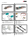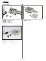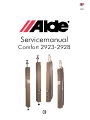
1
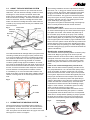
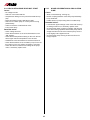
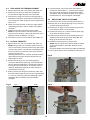
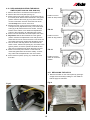
GB
Servicemanual
Comfort 2923-2928
SE
Contents
Page ChapDesignation
11
11
12
12
13
13
13
14
14
14
15
15 16
16
17
17
17
18
18
19
20
21
22
23
24
25
26
Page ChapDesignation
3
3
4
4
5
5
6
7
7
7
7
7
8
8
8
8
9
9
9
9
9
10
10
1:0
1:1
2:0
2:1
3:0
3:1
4:0
5:0
5:1
5:2
5:3
5:4
5:5
5:6
5:7
5:8
5:9
5:10
5:11
5:12
5:13
5:14
5:15
About the Alde Heating System
Operating the Heating System
About LPG
About LPG Installations
About the LPG Boilers
Technical Data
Flow Chart
Fault-Finding
General Fault-Finding
Ignition Spark - None or Only One
The Ignition Spark Does Not Stop
The Ignition Spark Starts when the Boiler is Switched Off
Pilot Burner does not Light
Pilot Burner Burns Yellow
The Pilot Burner Goes Out when the Thermostat Knob is Released
The Pilot Burner Goes Out when the Thermostat Knob is Turned Up
The Boiler Overheats the Water
The Boiler does not Heat Up
Ignition Flash in Main Burner
Noise in Main Burner (Roaring)
Impossible to Shut Boiler Off
The Circulation Pump does not Start
Noise or Vibration In Circulation Pump
6:0
6:1
6:2
6:3
6:4
6:5
6:6
6:7
6:8
6:9
6:10
6:11
6:12
6:13
6:14
6:15
6:16
6:17
6:18
7:0
8:0
9:0
10:0
11:1
11:2
12:0
12:0
Replacing Components on the Boiler
Replacing the Complete Burner Unit
Adjusting the Boiler Temperature
Replacing the Overheating Protection
Replacing the Thermo-Element
Replacing the Spark Plug
Replacing the Pilot Burner or Nozzle
Replacing the Main Burner
Replacing the Ignition Cable
Replacing the Ignition Transformer
Replacing and Adjusting the Micro-Switch
Replacing the Hatch
Replacing the Panel
Replacing the Control Box
Replacing a Complete Control Box with Panel
Replacing the 12 V Circulation Pump
Replacing the Motor on the 12 V Circulation Pump
Replacing the Expansion Chamber
Calibrating the Room Thermostat
Circuit Diagram
Exploded view 2923
Exploded view 2928
Exploded view 2923 / 2928 980
Article numbers to exploded view
Article numbers to exploded view
Spare parts
Spare parts
FOREWORD
This service manual is intended to assist with servicing and fault-finding in caravans, motor caravans and sheds equipped with Alde’s LPG boilers, types 2923 and 2928. The handbook may also be of assistance in ordering spare parts,
in understanding how the boilers operate, and how they are installed. It also includes general information on how our
heating systems are designed, and some information on LPG and LPG installations.
We hope that you will find this manual very useful, and that it will save you time during service and fault-finding on our
boilers.
Alde International Systems AB
Service Department
NOTE! We reserve the right to make changes after this manual has been printed.
1:0 About the Alde heating system The heating system consists of up to three heat sources,
LPG boiler, 230 volt electrical cartridge, as well as a heat
exchanger for motor caravans and boats. Alde’s LPG
boilers can be combined in many ways. Solely LPG - LPG
boiler and electrical cartridge - LPG boiler and warm water
heater or LPG boiler, electrical cartridge and warm water
heater. The electrical cartridge and warm water heater do
not take up any extra space when they are installed at the
rear of the boiler.
If the heating installation has been exposed to a temperature below - 25° C, the glycol content must be increased,
but not, however, above 50%. When topping up the liquid,
the glycol concentration should be checked to prevent
excess concentration. The glycol mix should be replaced
every second year, since its properties, such as corrosion
protection, degrade over time. The heating system must
never stand empty of the glycol fluid.
The liquid in the system is drained through a drainage tap
which is usually located under the caravan entrance.
Fig 1.
Re-filling with liquid:
Electrical
cartridge
Warm water
heater
LPG boiler
Ensure that the caravan or boat is level, and check that the
air screws and drainage tap are closed. Remove the upper
front plate on the boiler. Then slacken the plastic cap on
the circulation pump and lift up the pump. Then carefully
pour the glycol mix into the expansion chamber. When the
system is being filled, air-pockets may form, depending on
how the pipe-system was installed. (A good indications that
there is air in the system is when the heat only travels a few
metres along the pipe from the boiler, despite the fact that
the circulation pump is operating). To make refilling simpler,
use Alde’s filling pump (fig 3) which both fills and bleeds the
system automatically.
Drainage
tap
Air-screw
Convectors
Bleeding the system (manually):
The LPG boiler must be operating and the circulation pump
switched off. Begin by opening the air screws (see the
builders instruction book for their location). Keep them open
until liquid comes out of the spout at the air screw. Start the
circulation pump and let it run for a few moments. Check
whether the pipes and radiators all round the system are
warm.
The LPG boiler/electrical cartridge heats up a liquid mixture
consisting of water (60%) and glycol (40%). With the help
of a 12 volt circulation pump which is located in the expansion chamber of the boiler, or a 230 volt pump fitted to the
electrical cartridge, the warm glycol/water is circulated
round the system through pipes and radiators. The radiators, which are located along the outer walls, heat up the air
which rises and warms the walls and furniture. Since warm
air rises, it forms an air-barrier which keeps the cold away
from the windows. The temperature inside the caravan
is controlled by a 12 volt room thermostat. Thanks to the
design of the boiler, and to the fact that it is fitted inside the
caravan, incoming fresh air is warmed by the boiler’s own
heat.
Fig 2.
If the air has not know disappeared, proceed as follows: The LPG boiler must be operating, and the circulation pump switched off. If in a caravan lower jockey wheel
as far as possible, so that the caravan tilts. Let it remain
like that for several minutes, so that any air rises upwards
in the system. Open the air screw at the highest point, and
keep it open until all the air has escaped. Then wind the
jockey wheel to its maximum position and repeat the procedure in that position. Then return the caravan to the level
position and start the circulation pump. Check that heat
is present all round the caravan. When bleeding a bogey
wagon or motor caravan, it is easiest to park on a steep
slope or to lift the vehicle up using a jack. If in a boat consult the boat builders instructions. Ensure
all radiators are bled after filling the system if a calorifier
is incorporated check the bleed valve here if incorporated.
Allow all air to escape before operating of pumps. Operate
the boiler and circulation pump check once again for air
pockets and ensure all the system reaches temperature.
Roof vent
Window
Air intake
Convectors
Fig 3.
1:1 Operating the heating system
Check the liquid level in the heating system regularly, in
the expansion chamber of the boiler. The level should be
approximately 10 mm above the min. line with the boiler
cold. The system must be filled with a 40% glycol mix of the
same type as is used in car engines. Filling Pump
Art nr 1900 811
2:0 About LPG
2:1
LPG is a very clean burning fuel, officially called ”Liquid
Petroleum Gas”. This international designation is normally
shortened to LPG. It consists primarily of the gases butane
and propane. Propane has the advantage that it gasifies
down to -40°C, while butane performs badly below +10°C.
Propane as a gas is approximately 1.5 times heavier than
air, and butane is approximately twice as heavy as air.
This is extremely important to bear in mind in the event of
any gas leak, since the LPG remains in low-lying spaces.
Pure LPG has no smell, but to enable any gas leak to be
detected, a substance with a characteristic smell is added
(it smells like sulphur). It can be stored in the cylinder for an
unlimited time without any deterioration in quality.
LPG is non-toxic, but if bottled in concentrated form it will
give rise to some anaesthetic effects, breathing difficulties
and symptoms of suffocation and therefore may be avoided.
The LPG cylinder contains LPG both in liquid and in gas
form. When the cylinder is filled, the gas turns to liquid
through compression. When the cylinder valve is opened,
and the pressure in the cylinder falls, the liquid turns into
gas again. In a newly-filled LPG cylinder, approximately
80% of the LPG is in liquid form. In new and sometimes
in newly-filled LPG cylinders, an air-cushion may form at
the top of the cylinder. This can cause the LPG boiler to
be difficult to light, when the cylinder has been changed.
This air-cushion must be blown before the LPG-cylinder is
connected to the LPG-system. Open the cylinder valve and
blow in the air for 5-10 sek.
Alde 2923 and 2928 LPG boilers must be connected to the
LPG cylinder with approved reducing valves with a pressure working the same as on the data sheet on the boiler. A
shut-off valve, to shut off the LPG supply, must be fitted on
the supply side of the boiler. The LPG is taken to the boiler
with 8 mm pipes of copper or zinc-coated steel. If copper
pipes are used, support-sleeves must be fitted at the connections. The pipes must be carefully clamped at 500 mm
intervals with clamps which do not chafe the pipes. If the
pipes go through walls, floors etc, they must be protected
against chafing using a protector-sleeve of hose or similar.
The pipes must also be protected against spark-overs from
electrical cables.
LPG installations must always be pressure tested after
installation or service. If there are any leaks, identified the
position of the leak using a leak spray or soapy water
About LPG installations
NOTE! Naked flames must not be used in searching for
leaks.
For additional safety, we recommend the use of the Alde
Leak Tester No. 4071.
Some important points to bear in mind:
• Only use CE approved components
• Always use support-sleeves with copper pipes.
• Never use force in tightening connections.
• Inspect the rubber packing on the reducing valve when changing cylinders.
• LPG pipes must be replaced when the rubber begins to crack.
• Consult the Recreational Craft Directive or Recreational Vehicle Directive regarding LPG installation.
Note! Be careful when blowing the LPG-cylinder. Never
blow against a person or near open fire or simular.
When LPG is burned completely, only carbon dioxide (C02)
and water vapour (H2O) are given off, just as in our own
exhaled air. In the event of incomplete combustion, however, carbon monoxide (CO), which is an extremely toxic
gas, is formed.
The flames from the burner must have a blue-green core,
the primary flame, and a pale blue secondary flame around
this. To ensure complete combustion, a good supply of air
is required.
LPG burners normally work at a lower pressure than that in
the cylinder. Alde’s LPG boilers work at a pressure of 28/37
mbar. This reduction in pressure is achieved by passing the
LPG through a reduction valve, which is screwed on top of
the LPG cylinder, or on to an automatic LPG connector.
Fig 6. Filled cylinder of LPG, cutaway diagram.
Safety valve
Cylindervalve
Outlet
Gas
Pressure ranges
Low pressure Reduced pressure 0 - 50 mbar
Intermediate
High pressure
Reduced pressure above 50 mbar up to 2.0 bar. Low pressure and intermediate pressure are always reduced pressures which are regulated by a reducing valve.
Liquid
Unreduced pressure or pressure over 2.0 bar. High pressure is used principally for camping equipment and special heating burners. 3:0 About Comfort LPG boilers 2923 & 2928
Boiler layout (fig 9):
Fig 7.
At the bottom of the LPG burner 2923 there is an inlet pipe
which feeds in air from outside to the combustion chamber
(fig 7). On the LPG boiler 2928, the air is led from the top
of the flue via a hose down to the combustion chamber
(fig 8). The LPG automatic unit and burner are attached to
a removable plate screwed into the combustion chamber
in the lower section of the boiler. The water jacket is fitted
above the combustion chamber, and consists of an inner
and outer pipe. The gap between these pipes provides
the water reservoir. Inside the inner pipe there is a flamedamper, which consists of a folded stainless plate. This is
intended to direct the warm combustion gases coming from
the burner out towards the water jacket to heat the water.
A pipe leads from the upper part of the water jacket to the
expansion chamber. Inside the expansion chamber there
is a 12 volt pump which circulates the heated liquid in the
system. A control unit with thermostat knob, fuse, current
inlet and change-over switch is located below the expansion chamber.
At the highest point of the boiler, there is an exhaust pipe
for connecting to the flue, as well as a connection block for
electrical connections to the boiler.
A ventilation drum is fitted alongside the boiler, and this
takes in fresh air from outside and directs it on into the
boiler. The fresh air is warmed up by radiant heat from the
boiler casing, and is then passed out into the caravan via
the ventilation grill in the front plate.
Exhaust
gases
Fig 9 (Comfort 2923).
Flue
Circulation pump
Expansion vessel
Burner
Level marks for
glycol liquid
Hatch
Combustion air in
Control panel
Boiler thermostat
Overheating
protection
Fig 8.
Exhaust
gases
Water jacket
Combustion air in
How the boiler works:
Flame damper
When the room thermostat demands heat, the circulation pump starts. The liquid in the system then begins to
circulate, and cold water enters the boiler. A sensor fitted
in the water jacket senses that the water is colder than the
temperature set on the boiler thermostat. The pilot light
ignites the main burner, which heats up the liquid and circulates it round the system. When the warmth in the caravan
reaches the temperature set on the room thermostat, the
circulation pump stops. A sensor on the boiler senses
when the liquid has reached the temperature set on the
boiler thermostat. It then closes down the main burner, and
returns to the pilot light. When later the liquid temperature
has fallen a few degrees in the boiler, the main burner is
ignited again. This ensures that warm water is always available when the room thermostat demands heat
Window
Burner
Ventilation duct
Inlet funnel
Burner
3:1 Technical data
Height:...................................................... 1710 mm
Width:....................................................... 132 mm
Depth:....................................................... 220 mm
Weight 2923 complete:............................. 18 kg
Weight 2928 complete:............................. 19 kg
Output propane:....................................... 5,4 kW
Output butane:.......................................... 6,2 kW
Gas pressure:........................................... 30 mbar(3 kPa)
Gas consumption propane:...................... max 420 g/h
Gas consumption butane:........................ max 480 g/h
Volume of liquid:....................................... 2,6 litre
System temperature:................................ 35 - 75 °C
Fuse:........................................................ 1 amp
Current consumption 12 V circ. pump:..... 150 - 200 mA
Connection pipes heating system:........... Ø 22 mm
Minimum installation dimensions for 2923:
Height:...................................................... 1820 mm
Width:....................................................... 132 mm
Depth:....................................................... 310 mm
Minimum installation dimensions for 2923:
Height:...................................................... 1850 mm
Width:....................................................... 132 mm
Depth:....................................................... 350 mm
4:0 Flow chart
LPG Boiler
Circulation pumpOutput electrical cartridge
12 V
12 V
12 V
Fuse
Fuse
Fuse
Microswitch
ON/OFF
Room
thermostat
ON/OFF
Room
thermostat
K
N
N
Ignition
transformer
Switch
Switch
Spark plug
Switch
12 / 230 V
Switch
1 kW / 2 kW
0
Circuit
board on
el. cartridge
1050 W
Relay on
el. cartridge
for 230 V
circ.pump
1050 W
12 V
Circulation pump
5:0 Fault-finding
- If the ignition transformer produces a spark (click), but
there is no spark at the spark plug, first check the ignition
cable by removing it from the spark plug and making
a connection approx. 3-5 mm from earthed material. If
there is a spark between the connection and the material,
there is no fault in the ignition cable, and the fault lies
in the spark plug which must be replaced. If there is no
spark, but a ticking is heard from the ignition transformer,
the fault is in the ignition cable.
- If there is only one single spark (the lamp flashes once)
this is due to the effect on the spark plug of dampness or
condensation. The spark plug/ignition cable is then faulty,
and must be replaced.
5:1 General fault-finding
This guide to general fault-finding should be useful in
rapidly establishing where in the heating system the fault
may lie. This saves time in fault-finding. For more detailed
fault-finding, see sections 5:2 - 5:15.
Fault
Possible fault in
Boiler does not start
Gas supply, fuse,
ignition system
Boiler/electrical cartridge
not warm
Temperature-settings,
boiler thermostat, electri-
cal cartridge thermostat
Boiler/electrical cartridge
warm, but no heat in the
caravan or boat Circulation pump, air in
heating system,
warm water heater
Boiler/electrical cartridge boiling
Temperature-settings
boiler thermostat, electri-
cal cartridge thermostat
Noise in circulation pump
12/230 V
Liquid level, air in the
system, foreign object in
pump housing, pump
motor, paddle wheel
Uneven temperature in
the caravan or boat
Regulating equipment
room therm., connections
Too little warm water
System temp, circulation pump, water-flow
NOTE! When this fault occurs, the boiler can be jumpstarted by removing the ignition cable from the lighter and
attaching it 3 - 5 mm from the connection pin so that it
forms an extra spark gap. Start the boiler in accordance
with the instructions. Remove the fuse and connect the
ignition cable when the boiler starts. Replace the fuse. 5:3 The ignition spark does not stop after ignition
Cause:
- The ignition cable has loosened at the connection to the
lighter or the spark plug.
- Break in the ignition cable.
- Ignition electrode not in centre of pilot flame.
- Pilot flame too small.
- Fault in ignition transformer.
Remedial action:
- Check that the ignition cable is correctly connected or
replace the ignition cable.
- Adjust the ignition electrode so that it is in the centre of
the pilot flame.
- Check the gas supply and nozzle in the pilot burner.
- Replace the ignition transformer.
5:2 Ignition spark - none or only one Cause:
- Voltage to ignition transformer absent or too low.
- Fault in ignition transformer.
- Insulation fault on spark plug.
- Insulation fault on ignition cable.
- Fouling/dirt on spark plug.
5:4 The ignition spark starts when the boiler is switched off
Cause:
- Micro-switch wrongly adjusted.
- Thermostat knob turns too easily.
- Thermostat knob turns too slowly.
Remedial action:
- Check that there is 12 V voltage on the boiler connection
block between pins 1 red (+) and 4 black (-).
- Check that the fuse in the control panel is intact.
- Check that the micro-switch trips when the thermostat
knob is turned to the ignition position. Use a voltmeter to
measure the voltage between the yellow (+) and black (-)
cables on the ignition transformer. This must be > 9 V.
- Check the ignition transformer by removing the ignition
cable from the connection and turning the thermostat
knob to the ignition position. The ignition transformer
should then produce a spark (click) and the indicator
lamp should flash continuously. If not, the ignition transformer is faulty and must be replaced.
Remedial action:
- Adjust the micro-switch in accordance with chap. 6:10.
- Check that there is an o-ring in the groove on the shaft
of the thermostat knob, and that there is not too much
grease on the shaft and in the knob hub, wipe any excess
away.
- If the knob feels springy (does not remain in the position
in which it is released), lubricate the o-ring very sparingly
with grease.
- Replace the thermostat knob.
NOTE! When the thermostat knob is removed, it must be
re-fitted in the same position, otherwise the temperatures
setting will change. 5:5 Pilot burner does not light
Cause:
- Check the operation of the overheating protection by
measuring voltage between points 1 and 3 (there is a
voltage drop of approx. 5 mV compared with points 1 and
2). If a measuring instrument is not available, short circuit
the upper and lower pins (2 and 3) with a screwdriver, for
example. If the pilot flame goes out when the screwdriver
is removed, the overheating protection must be replaced.
- Replace the automatic unit.
- No ignition spark at the pilot burner.
- Gas supply absent or too little.
- Nozzle and/or burner clogged.
Remedial action:
- Check ignition in accordance with Chapter 5:2.
- Check the gas supply.
- Check that the cylinder valve and the main tap on the
boiler are open and that the reducing valve provides the
correct pressure (28/37 mbar). Check whether other LPG
appliances, e.g., cookers, can be lit and burn normally at
full output.
- Check and blow clean the pilot burner and nozzle.
- Replace the pilot burner.
Fig 10.
Overheating protection
3
5:6 Pilot burner burns yellow Cause:
1
- Dirt in the nozzle and/or pilot burner.
Remedial action:
2
- Check and blow clean the pilot burner and nozzle.
- Replace the pilot burner.
5:7 The pilot burner goes out when the thermostat knob is released
Cause:
Thermo element
Nuts
Joint nipple
5:8
The pilot burner goes out when the thermostat knob is turned up
Cause:
- Thermostat knob has not been pressed fully in.
- Thermostat knob has been released too early.
- Faulty thermo-element, produces no voltage or insufficient voltage.
- Thermo-element insufficiently heated as a result of weak
(yellow) flame and/or wrongly-placed thermo-element tip.
- Contact between thermo-element and magnetic insert in
the automatic unit poor or non-existent.
- Fault in overheating protection.
- Fault in automatic unit.
- Fault in gas supply.
- Fault in air supply.
- Fault in flue.
Remedial action:
- Check that the cylinder valve and the main tap in the
boiler are fully open and that the reducing valve gives
the correct pressure (30 mbar). Check that other LPG
appliances, e.g. cookers, can be lit and burn normally at
full output.
- Check that the air inlet pipe/hose and funnel for the boiler
are undamaged and that the funnel is not clogged and is
fitted correctly.
- Check that the boiler exhaust flue and cowl are undamaged and are not clogged.
Remedial action:
- Check that the thermostat knob is pushed fully in and is
held for a minimum of 15 sec after the indicator lamp has
stopped flashing.
- Check the gas supply and the pilot burner in accordance
with 5:6. The pilot burner must burn with a clear blue
flame without yellow peaks.
- Check that the tip of the thermo-element is in the centre
of the pilot flame. Adjust if necessary by carefully bending
the bracket.
- Check, and, if necessary, clean the contact surfaces in
the joint nipple between the thermo-element, the overheating protection and the magnetic insert in the automatic unit, and that the nuts on the thermo-element are tight.
- Check the operation of the thermo-element by measuring
the voltage (see fig 10) between point 1 and the lower pin
of the over heating protection, point 2. It must be
> 15 mV. If the voltage is lower than this the thermo-element must be replaced. 5:9The boiler overheats the water
Cause:
NOTE! If the modulating screw is adjusted down, the
main burner lights and switches off with reduced
output, ”modulation”, which gives a more gentle start.
If this has been done, check that the main flame burns
silently and steadily at reduced output (after start and
before stopping the main burner may begin to vibrate
if the setting is wrong). The standard setting is approx.
1/2 turn open.
- Max temp setting too high.
- Faulty boiler thermostat/sensor.
- Sensor not fixed to boiler casing.
- No heat-conducting paste between sensor and boiler.
Remedial action:
- Check in the expansion chamber that the heating system
is filled to the correct level with 40% glycol mix.
- Check that the sensor is attached, with heat-conducting
paste between the boiler and the sensor, and that the
capillary tube is not damaged.
- Turn the thermostat knob to position 1 and check that the
main flame goes out, and if it does, lower the max temp
setting. If the flame does not go out, replace the sensor
or automatic unit.
5:12 Noise in main burner (roaring)
Cause:
- Exhaust cowl wrongly fitted or missing.
- Inlet pipe/hose wrongly fitted or missing.
- Faulty main burner or nozzle.
- Modulating screw on automatic unit wrongly set.
Remedial action:
- Check that the exhaust cowl is correctly fitted in accordance with the installation instructions.
- Check that the inlet funnel is black and is correctly fitted.
(The inlet funnel on the type 2923 burner has a smaller
through-flow of air and is manufactured in black material
to avoid confusion with the grey unit which fits type 2920
and 2921 boilers).
- Replace the main burner. If a new standard burner does
not help, a special burner can be fitted, which has a greater hole diameter on the burner screen (can be ordered
after discussion with Alde service).
- Adjust the modulating screws on the automatic unit by
screwing out (anti-clockwise) until the vibrations disappear (see fig 11). The standard setting is approx.
1/2 turn open.
- Replace the automatic unit.
NOTE! When using the heating system at high altitude
(more than 1000 m above sea-level ) the boiling point
of the glycol mix is reduced through lower atmospheric
pressure, and this may cause boiling if the thermostat
knob is in its maximum position (7). Turn down to position 6 or 5 to avoid boiling.
5:10 The boiler does not heat up Cause:
- The main burner does not ignite/burns with insufficient
output.
- Main burner goes out (breaks) too early.
Remedial action:
- Check that the nozzle in the main burner is not clogged
and has the correct rating (220 for 28/37 mbar and 190
for 50 mbar gas pressure) Remove, blow clean or replace
nozzle if necessary.
- Check the boiler temperature, if necessary adjust the
temperatures setting.
- Replace the automatic unit.
5:13 Impossible to shut boiler off Cause:
- The spindle for the ignition fuse is stuck in the depressed
position.
Remedial action:
5:11 Ignition flash in main burner Cause:
- Lubricate the spindle (see fig 11) with silicone oil.
- Replace the automatic unit.
- Faulty or wrongly-adjusted pilot burner.
- Faulty main burner/nozzle.
- Modulating screw in automatic unit wrongly set.
Fig 11
Screwdriver
Remedial action:
- Check that the pilot burner is as low down as possible on
the main burner, so that the ignition flame sweeps close
to the top of the main burner. Adjust the height if necessary by slackening the two screws in the pilot burner
bracket.
- Check that the pilot burner burns with a blue flame at the
outlet hole towards the main burner. Replace the pilot
burner if necessary.
- Check that the screens at the top of the main burner are
intact and firmly attached, and that the main nozzle is
intact. Replace burner and/or nozzle if necessary.
- Adjust the modulating screws on the automatic unit by
screwing down (clockwise) until the boiler lights softly
(see fig 11)
Adjustment screw
Spindle for ignition fuse
5:14 Circulation pump does not start
Cause:
5:15 Noise or vibration in circulation pump
Cause:
- No voltage to boiler.
- Switch on room thermostat off.
- Temperatures setting too low (room thermostat has tripped).
- Room thermostat wrongly calibrated or faulty
- Switch for circulation pump on control panel in wrong
position/faulty.
- Cable connections not attached to motor.
- Pump motor faulty.
- Wear in motor/bearing - bearing dry.
- Rubber coupling between motor and pump shaft faulty.
- Pump shaft bent.
- Paddle wheel in pump housing does not rotate freely.
Remedial action:
- Lubricate the upper bearings of the motor with one drop
of sewing machine oil, if necessary replace motor.
- Check that the rubber coupling is straight, and does not
move about during operation and that the pump shaft is
straight. Slacken the nut which hold the pump, turn the
pump slightly and re-tighten the nut.
- Check that the pump housing is clean and free from
foreign objects.
Remedial action:
- Check voltage and fuse.
- Check that the switch on the room thermostat is in the
”ON” position.
- Check that the temperature setting on the room thermostat is higher than the temperature in the caravan.
- Calibrate the room thermostat in accordance with 6:18.
- Check that the switch for the circulation pump on the control panel is in the 12 V position and that it is not faulty.
- Check the cable connections and voltage at the pump
motor, if necessary replies motor.
10
12.Open the main gas tap to the boiler. Remove the hose
from the reducing valve on the gas tube, fit a manometer and pressure test the LPG installation in accordance
with instructions. Attach the hose, open the gas pipe
and test-run the boiler. Check that sparks cease when
the boiler lights!
6:0 Replacing components This Chapter shows the easiest way of replacing components in an Alde Comfort boiler.
NOTE! Work on the automatic gas unit may only be
carried out by Alde’s service department or authorised
personnel. 6:1 Replacing the complete burner unit
1. Close the main gas tap to the boiler.
2. Remove the hatch on the control panel by opening it
straight out and carefully bending it upwards in the
centre so that the pegs are released (see chapter 6:12).
3. Remove the lower front plate (see fig 12). Lever with a
screwdriver in the groove on the bottom of the plate until
the tabs are clear. Then pull outwards/downwards until
the plate is free and can be removed.
4. Switch off the main current switch or remove the fuse on
the control panel. Set the thermostat knob in the ignition
position. Remove screw (fig 15 A) which holds the rod in
the automatic knob. Press the knob down and carefully
lift the rod from the knob.
5. Unfasten the springs (fig 13 A) which hold the sensor (fig
13 B) and overheating protection (fig 13 C) and remove
these from the boiler casing, se fig 14. Disconnect the
ignition cable from the ignition transformer (fig 13 D), as
well as the screw to the earthed connection (fig 15 B).
6. Remove the remainder of the screws, 13 off B6 x 9 (fig 15 C) in the burner plate.
7. Disconnect the inlet gas pipe to the automatic unit (fig 15 D) and remove the burner unit from the boiler,
see fig 16.
8. Check that the front packing (fig 16 A) is intact before
the burner unit is replaced. Fasten the burner unit and
earth cable. Attach the inlet gas pipe to the burner unit
and tighten. Install the overheating protection, sensor
and ignition cable. Ensure that there is heat-conducting
paste between the sensor and the boiler. Check that
the capillary tube to the boiler thermostat, overheating
protection and ignition cable are correctly installed to
the right of the automatic unit, and are not trapped or
damaged.
9. Fit the rod in the automatic knob and insert the screws.
Carefully turn the knob to the stop position and check
that the micro-switch ”clicks”, switches off.
10.Fit the fuse and switch on the main switch. Turn the
thermostat knob to the ignition position and check that
the indicator lamp flashes and that there is a spark at
the spark plug. Press down the thermostat knob and
turn to no. 7 on the scale. Check that the arm of the
micro-switch does not drag against the knob hub. (If
necessary adjust the micro-switch, see Chapter 6:10).
Turn to the stop position and check that the spark is
switched off and that the lamp stops flashing.
11.Install the lower front plate (fig 12), push the upper
parts under the edge of the control box, press the plate
inwards/downwards so that the tabs grip the boiler foot.
Fit and close the hatch.
Fig 12
Fig 14
Fig 13
B
D
A
C
Fig 16
Fig 15
A
A
D
B
C
11
6:2 Adjusting the boiler temperature
6:3 Replacing the overheating protection
1. Remove the hatch on the control panel by opening it
straight out and carefully bending it in the middle so that
the pegs are released (se Chapter 6:12).
1. Remove the lower front plate (see fig 12).
2. Unfasten the springs (fig 13 A) which hold the sensor (fig
13 B) and overheating protection (fig 13 C) to the boiler
casing.
2. Remove the lower front plate (see fig 12).
3. Switch off the main power switch, set the thermostat
knob in position 2, so that the hole with the figure 5
on the automatic unit knob is straight ahead. Unfasten
the screws (fig 17 A) on both sides of the plastic conductor on the rod. Push the rod and knob to the side.
Remove the white plastic plug, press down the nozzle
and remove the screw with a 7 mm spanner, (with serial
numbers from 21425, a special tool is required for removing the screw.) Remove knob and spring (see fig 17).
3. Unwind the sensor from the overheating protection.
4. Slacken the nuts on the thermo-element (fig 19 A) a
couple of turns in the joint nipple (fig 19 B) below the
automatic unit and then pull the overheating protection
straight out of the joint nipple (see fig 20). Check that
the joint metal is free from oxidation, if necessary clean
or replace it.
5. Fit the new overheating protection into the joint nipple.
Tighten the nuts from the thermo element, but not too
much. Check that the cables for the overheating protection are not lying against the gas pipe.
4. Temperature adjustment: Note the scale on the edge
of the plastic wheel (corresponds to the scale on the
knob) and the index on the cover. Lift the plastic wheel
approximately 10 mm (see fig 18). Turn anti-clockwise
to reduce the temperature and clockwise to increase it.
Carefully push the plastic wheel down so that the teeth
engage, every tooth movement is equivalent to approx.
3°C change in temperature.
6. Wind the sensor wire round the new overheating protection and attach the sensor with spring in the recess in
the boiler casing. Check that there is heat - conducting
paste on the sensor.
7. Tilt the overheating protection at the top and push it
down into the holder. Attach it with the spring.
5. Fit the spring, knob and screw. Turn the knob to the stop
position, switch on the main switch/insert fuse. Start and
test-run the boiler at max temp (knob in position 7) with
the circulation pump switched off. Check that the boiler
switches off (main burner goes out) at the correctly set
system temperature. If necessary, make further adjustments.
8. Start the boiler in accordance with instructions. Check
that the boiler continues to burn when the thermostat
knob is released. Fit the lower front plate (see fig 12)
Fig 19
Basic setting of temperature: With the sensor in a water
bath, temperature 70°C, turn the thermostat knob from
position 7 towards 1, switching, ”ticking” occurs between
positions 6½ - 4½. On burner unit with serial numbers >
28798, the water bath must be at 65°C.
B
6. Press in the plastic plug, fit the rod with the plastic adapted, (NOTE! The figure 5 must be visible in the hole).
Turn to the stop position, check that the spark shuts off
and that the lamp stops flashing.
A
7. Fit the lower front plate (see fig 12). Install and close the
hatch.
Fig 17
Fig 18
A
_
Fig 20
+
12
6:4 Replacing the thermo-element 4. Insert the burner unit into the boiler and install it in
accordance with Chapter 7:1. Check that the capillary
tube to the boiler thermostat, the temperature limiter
and ignition cable are aligned correctly, to the right of
the automatic unit, and not trapped or damaged.
1. Remove the burner unit in accordance with Chap. 6:1.
2. Slacken the nut (fig 21 A) a few turns and pull the
thermo-element (fig 21 B) down out of the holder.
3. Unscrew the nut (fig 19 A) from the joint nipple (fig 19
B) below the automatic unit and pull out the thermo-element through the cable opening on the front plate of the
burner unit.
6:6 Replacing the pilot burner
1. Remove the burner unit in accordance with Chap. 6:1.
2. Slacken the nut on the gas pipe (fig 21 E) on the pilot
burner and pull down the pipe.
4. Check the contact surfaces on the joint nipple and the
overheating protection, clean or replace joint nipple if
necessary.
3. Slacken the nut (fig 21 A) to be thermo-element a few
turns and pull it down out of the holder.
5. Install the new thermo-element in reverse order.
NOTE! The tip of the thermo-element must be pres�sed up as far as it will go in the holder, before the nut is
tightened. Check the distance, see fig 21.
4. Unscrew the nut (fig 21 C) which holds the spark plug
and pull it down from the holder.
5. Remove the pilot burner from its bracket (fig 23 A) by
slackening the screw (fig 22 A) from the holder and
lifting up the pilot burner, see fig 23.
6. Then fit the burner unit in accordance with Chapter 6:1.
6:5 Byte av tändstift
6. Install the new pilot burner in reverse order. NOTE! The tip of the thermo-element must be pushed
up as far as possible in the holder, before the nut is
tightened. Check the distans to the spark plug and thermoelement.
1. Remove the burner unit in accordance with Chap. 6:1.
NOTE! Inlet gas pipes do not always need to be removed, but if necessary must be pushed to the side to gain
access to the screws. The bulb and overheating protection do not need to be removed. This saves both time
and unnecessary work.
Carefully press the burner unit down and fold out at the
upper edge far enough to allow the pilot burner and
spark plug to be seen.
7. Then re-fit the burner unit in accordance with Chap. 6:1.
Fig 22
2. Slacken the nut (fig 21 C) on the spark plug and
unscrew. Pull down the spark plug, nut and cable with
silicone sleeve and take them out at the side. Remove
the plug from the cable and nut, and destroy it immediately by bending the electrode so that it cannot be
confused with a new plug.
A
3. Fit the nut to the new plug and connect the cable. Pull
the silicon sleeve (fig 21 D) over the joint, approximately
5 - 8 mm on to the plug. Insert the spark plug in place
and tighten the nut carefully. Check the distans, see fig 21.
Fig 21
4 mm
Fig 23
6 mm
B
A
A
C
D
E
13
6:7 Replacing the main burner
6:9 Replacing the ignition transformer
1. Remove the burner unit in accordance with Chap. 6:1.
2. Remove the pilot burner in accordance with Chap. 6:6.
3. Slacken the nut on the gas pipe below the main burner
(fig 24 A) and pull the pipe out for a short distance. Then
slacken the nut which holds the main burner (fig 24 B)
with a 17 mm spanner. Remove the main burner.
4. Transfer the angle bracket (fig 23 A), which holds the
pilot burner, on to the new main burner and attach the
pilot burner.
5. Install the main burner and tighten the nut and then the
gas pipe.
6. Fit the spark plug, gas pipe and thermo-element to the
pilot burner.
7. Fit the burner unit and test-run in accordance with Chapter 6:1.
Ignition transformer 2923 119 replaces with 2923 125.
1. Switch off the main power switch or remove the fuse on the panel.
2. Remove the lower front plate (see fig 12).
3. Pull out the ignition cable (fig 25 A) and connection
cables (fig 25 B) from the ignition transformer. Cut off
both bracket clips (fig 25 C) which hold the ignition
transformer.
4. Fit the new ignition transformator and connect the earth
cable (in mounting kit 2923 225) in the screw below (fig
26 A). Drill a Ø 4 mm hole through the control box for
the upper screw (fig 26 B) and thightend the ignition
box.
5. Connect the earth cable in the burner unit. If the boiler
already has the earth cable in the wiring loom from the
black ignition transformer, shall it be removed and cut
off (see fig 26 C).
6. Connect the cables on the new ignition transformer,
black at left, yellow in the middle and green at the right.
below. Connect the ignition cable (fig 26 D).
7. Fit the fuse or switch on the main power switch. Light
the boiler, check that the spark ceases when the boiler
has ignited!
8. Fit the lower front plate (see fig 12).
Fig 24
Fig 25
C
B
B
A
Part no
2923 119
6:8 Replacing the ignition cable
A
1. Remove the burner unit in accordance with Chap. 6:1.
NOTE! Inlet gas pipes do not always need to be removed, but if necessary must be pushed to the side to
gain access to the screws. The sensor and overheating
protection do not need to be removed. This saves both
time and unnecessary work.
Carefully press the burner unit down and fold out the
upper edge far enough to allow the pilot burner and
spark plug to be seen.
2. First remove the ignition cable from the ignition transformer and then from the spark plug and pull it out through
the table opening on the front plate of the burner unit.
3. Fit the new ignition cable and connect it to the spark
plug and ignition transformer. Don’t firget the silicone
sleeve.
4. Push the burner unit into the boiler and install it in accordance with Chapter 6:1. Check that the capillary tube
to the boiler thermostat, the temperature limiter and the
ignition cable are correctly aligned, to the right of the
automatic unit, and are not trapped or damaged.
C
Fig 26
B
C
A
Part no
2923 125
14
D
6:10 Replacing/adjusting the micro-
switch (Not 2923 980 och 2928 980)
FIG 28
1. Remove the hatch in accordance with Chapter 6:11.
2. Remove the lower front plate (see fig 12).
3. Switch off the main power switch or remove the fuse on
the control panel. Set the thermostat knob in the ignition
position. Remove the screw (fig 15 A) which holds the
rod in the automatic unit knob. Press the knob down
and carefully lift the rod out of the knob.
4. Slacken the inner screw on the micro-switch (fig 27 A)
a couple of turns (adjustment screw), remove the outer
screw (fig 27 B). Removed the micro-switch, note the
location of the cables, move cables and adjustments
screws to the new switch, fit and tighten the screws.
5. Fit the rod in the automatic knob and replace the screw.
6. Adjustment: Set the thermostat knob in the ignition
position. Slacken the adjustment screw and place the
switch with its arm as close to the boss on the knob hub
as possible (see fig 28). Tighten the adjustment screw.
7. Turn the knob to the stop position and check that the
switch ”clicks”, switches off (see fig 29). Turn back to the
ignition position, check the operation and that the arm
does not rub against the hub when the knob is turned.
8. Switch on the main power switch or insert the fuse,
check that ignition/shut-off functions reliably. If necessary, make further adjustments to the micro-switch.
9. Fit the lower front plate, (see fig 12). Install and close
the hatch.
Position of microswitch at start position
FIG 29
Position of microswitch at stop position
FIG 30
Position of microswitch at maximum
position
6:11 Replacing the hatch
1. Remove the hatch on the control panel by opening it
straight out and carefully bending it in the middle so
that the pegs are released..
Fig 31
Fig 27
B
A
15
6:12 Replacing the panel
6:13 Replacing the control box
1. Remove the hatch in accordance with Chapter 6:11.
2. Switch off the main power switch.
3. Remove the lower front plate (see fig 12).
4. Pull the electrical contact from the top cover. Unfasten
the connection block and the earthed connection on the
top cover, the earth cable on the burner unit, as well as
the cables on the circulation pump. Pull out the connection block from the electrical cartridge, pull forward and
unfasten the cables and ignition cable from the clips.
5. Remove the panel by pressing downwards with a screwdriver in the groove on the upper edge of the panel (see fig 32 A), so that the locking bosses (fig 32 B)
release and the panel and its cables can be pulled out, see fig 33.
6. Assembly takes place in reverse order. Then switch
on the main power switch, turn the thermostat knob to
be ignition position and check that the indicating lamp
flashes and that there are sparks at the spark plug. Then carry out a complete functional inspection of the
control panel to ensure that all functions are OK.
7. Fit the lower front plate (see fig 12). Fit and close the
hatch
1. First remove the panel in accordance with Chap. 6:12. (1-5).
2. Set the thermostat knob in the ignition position. Remove
the screw which holds the rod to the automatic knob
(see fig 15 A). Press the knob and carefully lift the rod
from the knob.
3. Carefully push the rod up with the knob towards the control panel. Remove the screw (fig 34 A) and take away
the knob and rod.
4. Remove the control box by unscrewing the screws (fig 35 A) and pressing the catches (fig 35 B) inwards.
5. Transfer the ignition transformer and the micro-switch to
the new control box, note the location of the cables, fit
the cables. Then fit the panel into the control box.
6. Fit the connection block and the earthed connections in
the top cover, earth cable on the burner unit, the cables
to the 12 V circulation pump, as well as the connection
block to the electrical cartridge.
7. Install the control box by pressing it into the metal sweep
of the boiler until the catches in the box lock. Drill four
new holes in the control box and attach it with screws
through the plate sweep.
8. Fit the top knob and screw it on to the rod. Then screw
the rod into the lower automatic unit knob. Check that
the setting on the upper knob corresponds to the setting
on the lower knob (it may be turned one-half rev wrong).
9. Connect the electrical contacts in the top cover of the
boiler. Switch on the main power switch, turn the thermostat knob to the ignition position and check that the
indicator lamp flashes, and that there are sparks at the
spark plug. If necessary, adjust the micro-switch. Carry
out a complete functional check on the control panel
to ensure that all functions are OK. Test-start the boiler
and check that the thermostat knob can rotate freely.
10.Fit the front plates (see fig 12) and close the hatch.
Fig 32
B
A
B
Fig 33
Fig 34
A
16
6:14
6:15
Replacing a complete control box with panel
1. Remove the hatch (6:11) and front plates (see fig 12).
2. Switch off the main power switch and set the thermostat
knob in the ignition position. Remove the screw which
holds the rod to the automatic knob (see fig 15 A). Press the knob and carefully lift the rod from the knob.
3. Carefully push the rod up with the knob towards the
control panel. Remove the screw (fig 34 A) and take
away the knob and rod.
4. Pull the electrical contact from the top cover. Unfasten
the connection block and the earthed connection on the
top cover, the earth cable on the burner unit, as well as
the cables on the circulation pump. Pull out the connection block from the electrical cartridge, pull forward and
unfasten the cables and ignition cable from the clips.
5. Remove the control box by unscrewing the screws (fig 35 A) and pressing the catches (fig 35 B) inwards.
6. Transfer the ignition transformer to the new control box,
note the location of the cables, fit the cables.
7. Fit the connection block and the earthed connections in
the top cover, earth cable on the burner unit, the cables
to the 12 V circulation pump, as well as the connection
block to the electrical cartridge.
8. Install the control box by pressing it into the metal
sweep of the boiler until the catches in the box lock.
Drill four new holes in the control box and attach it with
screws through the plate sweep.
9. Fit the top knob and screw it on to the rod. Then screw
the rod into the lower automatic unit knob. Check that
the setting on the upper knob corresponds to the setting
on the lower knob (it may be turned one-half rev wrong).
10.Connect the electrical contacts in the top cover of the
boiler. Switch on the main power switch, turn the thermostat knob to the ignition position and check that the
indicator lamp flashes, and that there are sparks at the
spark plug. If necessary, adjust the micro-switch. Carry
out a complete functional check on the control panel
to ensure that all functions are OK. Test-start the boiler
and check that the thermostat knob can rotate freely.
11. Fit the front plates (see fig 12). Fit and close the hatch.
1. Remove the upper front plate (see fig 12).
2. Disconnect the connection cables (fig 36 A) on the top
of the circulation pump or at the connection block.
3. Slacken the plastic nut (fig 36 B) and lift up the circulation pump from the expansion chamber.
4. Transfer the nut to the new pump and connect the
cables. NOTE! Polarity.
5. Lower the pump into the expansion chamber and tighten the nut.
6. Start the circulation pump and check the direction of
rotation in accordance with the arrow on the motor. If the direction of rotation is wrong, shift the cables on
the connections.
7. Fit the front plate.
Fig 36
A
B
C
6:16
A
B
Replacing the motor on the 12 V circulation pump
1. Remove the circulation pump in accordance with Chapter 6:15, paragraphs 1-3.
2. Unfasten the screws (fig 36 C) and pull out the motor
including the rubber coupling from the pump shaft.
3. Install the new motor including rubber coupling by first
pressing it on to the pump shaft and then attaching the
motor with the screws.
4. Re-install the circulation pump in accordance with
Chapter 6:15, paragraphs 4-7.
Fig 35
A
Replacing the 12V circulation pump
B
17
6:17
Replacing the expansion vessel
6:18
Calibrating the room thermostat
1. Check the temperature in the caravan with an accurate
thermometer.
2. Remove the cover by pressing in the clip on the left side
of the room thermostat, see fig 39.
3. Pull out the knob (fig 40 A) and move it the number of
degrees corresponding to the difference. Press in the
knob and check that it trips at the correct temperature
(at click should be heard at the right temperature when
the thermostat knob is turned from max to min).
4. Re-fit the cover.
1. Drain the heating system of approx. 2 litres of liquid.
2. Remove the upper front plate (see fig 12).
3. Slide the front jubilee clip (fig 38 A) backwards on the
rubber joint away from the outlet pipe on the expansion
vessel.
4. Unscrew the plastic nut (fig 36 B) and lift up the circulation pump and support (fig 37 A).
5. Detach the bleed hose (fig 37 B) from the top cover, and
the drain hose (fig 37 C) from the bottom of the boiler.
6. Unscrew the nut (fig 38 B) and then lift the vessel from
the pipe bend (fig 38 C) and remove it.
7. The o-rings (2 off) at the top of the pipe bend must be
replaced at the same time as the expansion vessel.
8. Fit the rubber connection on the connection pipe
before the vessel is fastened properly. Then pressed
the new expansion vessel down on to the pipe bend
and tighten the nut (fig 38 B) a few turns. Attach the
support (fig 37 A) and then tighten the nut. Fit the
hoses.
9. Close the drainage tap and top up the liquid in the
expansion vessel. Lower the circulation pump into the
vessel and screw on the plastic nut (fig 36 B). Attach the pump. Fit the front plate.
Fig 37
Fig 39
B
A
C
Fig 40
Fig 38
B
A
A
C
18
+
_
12 V DC
_
+
19
Black
12 V DC
12 V DC
Battery
Red
Red / White
Red
P
Red
Power input
N
Fuse
1A
Black
Electrical cartridge
(1000 W)
275 ohm
275 ohm
2000 W
Grey
220
Blue
(230 pump)
K
12
Pump
(1000 W)
Red
1000 W
Red
275 ohm
Room thermostat
Yellow
N
K
Black
_
+
Yellow
L
Black
Green
Ignition transformer
Yellow
Micro-switch
7:0 Circuit diagram 2923 & 2928
8:0Exploded view 2923
30
6
4
31
5
1
32
33
8
34
7
2
39
9
19
10
20
11
21
3
18
29
17
36
23
12
35 13
14
15
16
37
22
28
38
25
24
20
26
27
9:0 Exploded view 2928
31
6
4
31
5
40
1
41
33
34
40 39
8
35
7
45
9
38
2
19
10
20
11
21
3
18
29
17
42
36 13
23
12
14
15
43
22
16
28
37
44
25
24
21
30
26
27
10:0 Exploded view 2923 / 2928 980
27
5
3
4
28
1
29
30
6
7
8
18
9
17
26
16
20
32
15
10
11
31
19
12
13
14
33
25
2
34
22
21
22
23
24
11:1 Article numbers to exploded view
2923 page 20
2928 page 21
No
1.
2.
3.
4.
5.
6.
7.
8.
9.
10.
11.
12.
13.
14.
15.
16.
17.
18.
19.
20.
21.
22.
23.
24.
25.
26.
27.
28.
29.
30.
31.
32.
33.
34.
35.
36.
37.
38.
39.
No
1.
2.
3.
4.
5.
6.
7.
8.
9.
10.
11.
12.
13.
14.
15.
16.
17.
18.
19.
20.
21.
22.
23.
24.
25.
26.
27.
28.
29.
30.
31.
32.
33.
34.
35.
36.
37.
38.
39.
40.
41.
42.
43.
44.
45.
Part.no
2923 154
2923 111
2923 153
2930 423
2920 410
2930 410
2923 200
2923 210
2923 114
2923 113
2923 121
2920 270
2900 258
2923 207
2923 201
2920 245
2923 208
2920 230
2923 125
2930 133
2923 159
2930 236
2923 101
2923 301
2923 025
2923 173
2923 174
2920 123
2923 166
2923 197
2930 134
2930 119
2930 131
2930 132
2923 196
2920 142
2920 275
2900 271
2923 500
2923 112
Designation
Front plate upper complete
Hatch
Front plate lower complete
Plastic nut
Circulation pump complete (Dunker)
Expansion vessel complete
Control box complete (4 switches)
Panel complete (4 switches)
Micro-switch
Knob
Knob shaft
Gas valve compl.
Plate screw
Spark plug
Pilot burner
Thermo-element
Ignition cable
Overheating protection
Ignition transformer compl.
Spring
Handle
Front packing
Boiler casing standard
Boiler casing for 2959 warm-water supply
Bracket
Spacer
Spacer strip
Plug
Plate sweep
Escutcheon plate
Top cover
Expansion chamber holder
O-ring
O-ring
Plastic bush
Window
Knob compl.
Joint plug for overheating protection
Burner unit without ignition transformer and ignition cable
Control box
23
Part.no
2923 154
2923 111
2923 153
2930 423
2928 405
2930 413
2923 200
2923 210
2923 114
2923 113
2923 121
2920 270
2900 258
2923 207
2923 201
2920 245
2923 208
2920 230
2923 125
2930 133
2923 159
2930 236
2928 201
2923 025
2923 173
2923 174
2920 123
2923 166
2923 197
3118 000
2930 134
2930 119
2930 131
2930 132
2923 196
2920 142
2925 154
2923 171
1900 030
1900 120
1900 112
2920 275
2900 271
2923 500
2923 112
Designation
Front plate upper complete
Hatch
Front plate lower complete
Plastic nut
Circulation pump complete (Airpax)
Expansion vessel complete
Control box complete (4 switches)
Panel complete (4 switches)
Micro-switch
Knob
Knob shaft
Gas valve compl.
Plate screw
Spark plug
Pilot burner
Thermo-element
Ignition cable
Overheating protection
Ignition transformer compl.
Spring
Handle
Front packing
Boiler casing for 2959 warm-water supply
Bracket
Spacer
Spacer strip
Plug
Plate sweep
Escutcheon plate
Drain hose 0,3 m
Top cover
Expansion chamber holder
O-ring
O-ring
Plastic bush
Window
Sleeve
Pipe
Rubber plug
Jubilee clip
Rubber connector
Knob compl.
Joint plug for overheating protection
Burner unit without ignition transformer and ignition cable
Control box
11:2 Article numbers to exploded view
2923 / 2928 980 page 22
No
1.
2.
3.
4.
5.
6.
7.
8.
9.
10.
11.
12.
13.
14.
15.
16.
17.
18.
19.
20.
21.
22.
23.
24.
25.
26.
27.
28.
29.
30.
31.
32.
33.
34.
Part.no
2920 131
2920 181 2930 423
2928 410
2930 413
2921 125
2923 410 2921 215
2921 219
2920 215
2920 270
2900 258
2923 207
2923 201
2920 245
2923 208
2920 230
2923 125
2930 133
2930 236
2923 301
2928 201
2923 025
2923 173
2923 174
2920 123
2920 167
2923 197
2930 134
2930 119
2930 131
2930 132
2920 142
2920 275
2900 271
2923 400
Designation
Front plate upper complete
Front plate lower complete
Plastic nut
Circulation pump complete
Expansion vessel complete
Wiring with connector
Panel complete (4 switches)
ON-OFF
ON-OFF-ON
Control box
Gas valve compl.
Plate screw
Spark plug
Pilot burner
Termoelement
Ignition cable
Overheating protection
Ignition transformer compl.
Spring
Front packing
Boiler casing for 2959 warm-water supply
Boiler casing for 2959 warm-water supply
Bracket
Spacer
Spacer strip
Plug
Plate sweep
Escutcheon plate
Top cover
Expansion chamber holder
O-ring
O-ring
Window
Knob compl.
Joint plug for overheating protection
Burner unit without ignition transformer and ignition cable
24
12:0 Spare parts
2923 400 Burner unit 2923 980 and 2928 980
2923 500 Burner unit 2923 and 2928
1
6
1
2
4
3
3
4
5
2
1. 2921 216
2. 2923 225
3. 2923 417
4. 2923 208
Ignition transformer compl.2923 980 and 2928 980
Ignition transformer compl. 2923 and 2928
Ignition cable. 2923 980 och 2928 980
Ignition cable. 2923 och 2928
1. 2920 230
2. 2923 207
3. 2923 201
4. 2923 114
5. 2920 245
6 2900 271
Overheating protection.
Spark plug.
Pilot burner.
Micro-switch (not mod. 980)
Thermo element.
Joint plug.
2
1
1
2
3
1. 2930 410
2. 2930 413
3. 2930 131
4. 2930 132
4
3
Expansion vessel, long pipe.
Expansion vessel, short pipe.
O-ring.
O-ring.
1. 2928 421
2. 2920 410
3. 2920 320
25
Cirkulation pump compl
Cirkulation pump compl
Motor to 2920 410 (Dunker).
12:0 Spare parts
2
1
2
1
3
1. 2923 210
2. 2923 200
3. 2921 217
4. 2923 115
4
Panel compl.
Control box compl.
Fuse 1 A.
Ignition lamp
1. 2923 112
2. 2923 111
4
3
2
1
1. 2921 215
2. 2921 219
3. 2920 215
4. 2923 410
Switch ON-OFF.
Switch ON-OFF-ON.
Control box (2923/2928 980).
Panel (2923/2928 980).
26
Control box.
Hatch
27
Wrangels allé 90 • Box 11066 • S-291 11 Färlöv • Sweden
Tel +46 (0)44 712 70 • Fax +46 (0)44 718 48 • www.alde.se • [email protected]
Service 2923 2928 Rev 916 GB
Alde International Systems AB