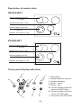
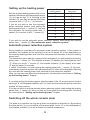
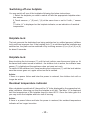
1
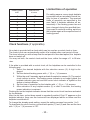
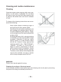
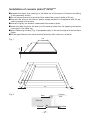
Ceramic plate with touch control Operating Manual P*4VQ2**** PB*4VQ2**** DEAR USERS, • • • • • • The Operating Manual has been compiled so that you may quickly yet thoroughly familiarise yourself with your new ceramic plate. Before using your ceramic plate for the first time, read this Operating Manual thoroughly and carefully. Familiarise yourself with your new appliance and its respective operating functions as they appear in the Manual. Observe all instructions and suggestions concerning proper use and maintenance of your plate as only thus can you ensure continuous readiness to work and long life for your appliance. Pay special attention to safety instructions. Try to avoid accidents and protect your plate against damage. Keep this Manual close at hand for further consultation. Disposing of the device When disposing of the device, do not bring it to regular municipal waste containers. Instead, bring it to electrical and electronic waste recycling and reuse center. A relevant label has been put on the device, its instructions manual, or on the package. The device has been manufactured of recyclable materials. By bringing old device to recycling collection center, you show that you care about nature. Ask your local environmental care authority for information on location of such facilities. -2- Table of contents Page Description ................................................................................................................ 4 Important hints ........................................................................................................... 7 Technical data ...........................................................................................................8 Proper cookware ......................................................................................................8 Operating instructions ............................................................................................... 9 Switching on the plate; hotplates ........................................................................... 10 Switching on double hotplate ................................................................................. 10 Setting up the heating power .................................................................................. 11 Automatic power reduction system .................................................................................1 1 Switching off the whole ceramic plate ..................................................................... 12 Switching off one hotplate ....................................................................................... 12 Locking the plate ..................................................................................................... 12 Residual hotplate temperature indicator ................................................................ 12 Limited time of operation ......................................................................................... 13 Clock. ...................................................................................................................... 13 Cleaning and routine maintenance ......................................................................... 14 Installation ............................................................................................................... 15 Connection diagrams................................................................................................18 -3- Description of ceramic plate (P*4VQ239T) Hotplate (back left) 145 Double hotplate (back right) 180/120 Double hotplate (front left) 180/120 Hotplate (front right) 145 Touch panel (display-indication) 6a 3 2 2 6b 4 1 5 7 -4- 1. Main sensor 2. Hotplate selection sensors 3. Hotplate indicators 4. Minus sensor 5. Plus sensor 6a. Double hotplate (back right) sensor with LED diode 6b. Double hotplate (front left) sensor with LED diode 7. Lock sensor with LED diode. Description of ceramic plate (PB*4VQ233F) Hotplate (back left) 145 Hotplate (back right) 180 Hotplate (front left) 180 Hotplate (front right) 145 Touch panel (display-indication) 2 5 7 3 2 4 1. Main sensor 2. Hotplate selection sensors 3. Hotplate indicators 1 4. Sensor - minus 5. Sensor - plus 7. Lock sensor with LED diode. -5- Description of ceramic plate PBF4VQ245FT Double hotplate (back left) 140x250 Hotplate (back right 180 Double hotplate (front left) 180/120 Hotplate (front right) 145 PG4VQ245FT Double hotplate (back left) 140x250 Hotplate (back right 180 Double hotplate (front left) 180/120 Hotplate (front right) 145 Touch panel (display-indication) 2 5 3 6b 2 7 6a 4 1 -6- 1. Main sensor 2. Hotplate selection sensors 3. Hotplate indicators 4. Sensor - minus 5. Sensor - plus 6a. Double hotplate (back left) sensor with LED diode 6b. Double hotplate (front left) sensor with LED diode 7. Lock sensor with LED diode. Important hints The manufacturer shall not be held liable for any damages incurred in consequence of improper usage of the appliance or its usage for purposes other that those specified in the Operating Manual. The ceramic plate purchased by you has been manufactured with the effective standards. When using the plate for industrial purposes, observe regulations effective for the industry. • Check that the plate has not incurred damage during transportation. • The ceramic plate can be installed only by a qualified fitter – electrician, to ensure the observance of VDE regulations and the “Technical connection conditions“. • In case of a failure, improper installation of the plate may result in loss of the warranty rights. • The plate can be used only after it has been fitted into furniture, as only then you will be protected against accidental contact with live components. • Make sure that electric conductors of other devices do not touch the heated hotplates. • Pay special attention when using power sockets located near the plate. • Never leave the plate unattended when cooking. • When in operation and some time after being switched off, the hotplates are still hot. • Please note that children will not be able to notice danger when you cook. Inform your children about the hazards or do not allow them to come near the plate when in operation. Do not let the children touch the plate when in operation. WARNING! Children may also get burnt by knocking the hot pots down. • Should there be a power failure, all the settings and indications will be cancelled. WARNING! Be careful when power is restored, as hotplates which have been hot before the power failure will no longer be controlled by their indicators. • When switched on, the hotplates quickly become hot. To avoid unnecessary power consumption, switch them on after placing a cooking pot on them. • Do not lay plastic objects (spoons, bowls etc.) on a heated hotplate as they will melt. • Do not cook empty enamelware. • Do not use plastic pots or containers made from aluminium foil, as they melt in high temperatures and may damage the ceramic plate. • Only pots with clean and dry bottoms can be put on your plate. • Be careful not to scratch the plate with jewellery or sharp-edged pots, so only use flat-bottom pots and saucepans on your ceramic plate, without sharp edges or burrs. • Please observe the maintenance and cleaning instructions. Should you fail to proceed in compliance with the provided guidelines, we will not be held liable under the warranty conditions. -7- • • If sugar or dishes containing sugar are spilled onto your plate, clean them immediately – still hot, if possible – to avoid chemical reactions which may damage the plate. See “Cleaning”. The ceramic heating plate is resistant to thermal shock. It is neither hot nor coldsensitive, although pointed hits, for example a fall of a bottle with spices or other small hard object, may in unfavourable circumstances lead to cracks and splits appearing on your ceramic plate. TECHNICAL DATA: Rated voltage: Hotplate: Hotplate: Hotplate: Hotplate: Dimensions: Weight: 400/230V, 50HZ 145mm 1200 W 180/120 mm 1700 W 180mm 1800 W 140x250 mm 2000 W 575 x 505 x 45; 576x 518 x 48 9,5 kg Proper cookware As hotplates are protected against overheating, the usage of proper cookware is of crucial importance. Unsuitable pots may cause the heating power to be reduced. Additional expenses incurred on special cookware are quickly returned by energy savings and longer life of both, the cookware and the ceramic plate. And besides, you will be able to reduce the time spent on preparing and cooking food. • • • Always use pots matching the diameter of the used heating element, allowing for efficient transfer of heat. When you use pots which are too small, not only the energy is lost but also the boiling over residuals of food may get burnt to the ceramic plate. Do not use pots with thin or convex bottoms, as they may cause the hotplate to be overheated. Special cookware for electric cookers with flat, polished bottoms are perfect for the purpose. -8- • • • Lids prevent the heat from escaping from the pot and thus shorten the cooking time and reduce the consumption of power. Always keep bottoms of your cooking pots dry, to avoid sediment depositing on your plate. When using special cookware, observe instructions provided by their manufacturers. Hotplate diameter d1 Pot diameter d2 12 cm ca. 14 cm 14,5 cm ca. 16 cm 18 cm d1 d2 ca. 20–24 cm Operating instructions The ceramic hotplates are equipped with electronic sensors (the control panel components) and are operated by touching the marked sensors with a finger („Touch-control”). Sensors’ activation is confirmed by a sound. -9- Please remember: When switching the plate on and off or adjusting the heating power always touch only one sensor (with the exception of switching off a hotplate or pot recognition function). If you touch more than one sensor at the same time, the system will ignore the entered settings and, should you keep touching the sensors for a long time, a fault signal will be emitted. Do not place any objects on the marked sensors (as a fault mode may be trigged) and keep them clean all the time. Switching on a hotplate If the plate is not in operation, all the hotplates are switched off and the display is blank. When you touch the main sensor (1), the plate switches on and all the hotplate indicators (3) show “0” for about 10 seconds. You can now set the required heating power by touching sensors “+”(5) or “-“ (4) (having selected a hotplate by touching sensor (2) – see Setting up the heating power). Should you fail to activate any sensor within 10 seconds, the plate will switch off automatically. If the children lock is active, the hotplates cannot be switched on. After switching on the plate with the main sensor (1), set the individual hotplates in the following manner: 1. Select the desired hotplate with appropriate sensor (2). The assignment of sensors to the respective hotplates corresponds with the hotplates’ layout. 2. Set the required heating power by touching sensors +” (5) or „-”(4). 3. To change the set heating power, proceed as in point 1, so first select the desired hotplate with appropriate sensor (2) and then adjust the heating power with „+” (5) or „-” (4) sensors. Should you fail to activate any sensor within 10 seconds, the hotplate will switch off. A hotplate is active when its indicator is lighted, which means that the hotplate is ready to give up the set heat. Double hotplate (if applicable) To switch on the additional, outer hotplate you have to touch the double hotplate sensor (6a,6b). A red LED diode (6a,6b) signals that the hotplate has been activated. To switch off the additional, outer hotplate, touch the double hotplate sensor (6a,6b) again. Advice: the additional, outer hotplate can only be activated when the inner hotplate is active. - 10 - Setting up the heating power Set the required heating power after you’ve selected a hotplate with appropriate sensor (2). As long as digit “0“ is flashing on the indicator (3), you may set the required heating power with „+” (5) or „-” (4) sensors. If you do not wish to use the automatic power reduction system, start setting the heating power from „+” sensor (5). You may then increase the heating power with „+” sensor (5) or reduce it with „-” sensor (4). Level of the heating power 1 2 3 4 5 6 7 8 9 Quick cooking time (min) 1 3 4,8 6,5 8,5 2,5 3,5 4,5 - If you wish to use the automatic power reduction system, start setting the heating power from „-” sensor (4). (See automatic power reduction system). Automatic power reduction system Every hotplate is provided with automatic power reduction system. If the system is activated, the hotplate will be switched on at its full power for a time depending on the selected heating power level and then the power will decrease to the set heating power level. The automatic power reduction system will be activated if you start setting the heating power from „-” sensor (4). The hotplate indicator (3) displays the heating power level “9”. When you touch “+” sensor (5), the hotplate indicator (3) will display a dot near “9” digit for about 10 seconds. If, within 10 seconds, you start setting the heating power with „-” sensor (4), the automatic power reduction system will be activated and “A” letter will be displayed, flashing by turns with the heating power level selected for the respective hotplate. Now, you can any time adjust the heating power, following the instructions of „Setting up the heating power” chapter. If you start setting the heating power after the lapse of the 10 second period, the dot near digit “9“ will disappear together with “A“ letter and the automatic power reduction system will stay inactive. If you do not wish to use the automatic power reduction system, start setting the heating power from „+” sensor (5). Now, you can any time adjust the heating power, following the instructions of „Setting up the heating power” chapter. Switching off the whole ceramic plate The plate is in operation as long as at least one hotplate is switched on. By touching the main switch (1) you can switch off the whole plate. Letter “H” is then displayed on the hotplate indicator (3) as an indication of residual temperature. - 11 - Switching off one hotplate You may switch off one of the hotplates following the below instructions: I. Select the hotplate you wish to switch off with the appropriate hotplate selection sensor. 2. Touch sensors „+” (5) and „-”(4) at the same time or set to 0 with „-” sensor (4). 3. Letter „H” is displayed on the hotplate indicator, as an indication of residual temperature. Hotplate lock The lock prevents the hotplates from being switched on by untitled persons (children lock) and from improper use. If the hotplate lock (7) is activated and the hotplates are switched on, the plate can be switched off by touching sensors (2) or (4) or (5) or (6) for about 5 seconds. Hotplate lock Keep touching the lock sensor (7) until the lock indictor near the sensor lights up. At the same time a short sound is emitted – the children lock is active, the indicator near sensor (7) is lighted and the appliance does not react on touch. To switch off the children lock, keep touching the lock sensor (7) until the lock indictor near the sensor goes out; again a short sound is emitted. Advice If there is a power failure and later the power is restored, the children lock will no longer be active. Residual temperature indicator After a hotplate is switched off, there will be “H” letter displayed by the respective hotplate indicators, informing you that the hotplate is still hot. The letter “H” is displayed until the temperature of the hotplate drops to about 60°C. Once the letter goes out you may touch the hotplate without a risk of burning. Advice If there is a power failure and later the power is restored, the residual temperature indicator will no longer be active. - 12 - Heating power level 1 2 3 4 5 6 7 8 9 Limited time of operation Maximal time in hours For safety reasons, every single hotplate is provided with an automatic device limiting its time of operation. The maximal times of operation are specified in the near Table. A hotplate switches off automatically if the heating power has not been changed during the specified time. If you want to continue cooking, switch on the hotplate again at the required level of heating power. 10 5 5 4 3 2 2 2 1 Clock functions (if applicable) Your plate is provided with a clock which can be used as a control clock or timer. The control clock can automatically switch off a hotplate after a set period of time. The timer informs you with a beep that the set period of time has lapsed, the hotplate does not switch off. You may set both, the control clock and the timer, within the range of 1 to 99 minutes. If the plate is provided with a control clock, all the hotplates can be controlled in the following way: 1. Select the desired hotplate with the selection sensor (2). A digit is displayed. 2. Set the desired heating power with „+” (5) or „-”(4) sensors. 3. Within the next 5 seconds, again activate the selection sensor (2). The control clock indictor is active. The heating power indicator is no longer lighted, the hotplate indicator goes out and the control clock indicator is lighted on the above or below indicator. 4. Set the time of operation for the hotplate with „+” (5) or „-”(4) sensors. 5. After activation of any hotplate sensor (2) or after 5 seconds, the heating power indication is restored. Flashing dot on the hotplate indicator shows that the control clock has been activated for the hotplate. After the set time, a short beep sound is repeatedly emitted. Digit “0” appears on the hotplate indicator, there are two horizontal lines displayed above or below and the hotplate is switched off. To change the already made setting, repeat the setting process from points 1 to 5. To deactivate the clock function, proceed with points (1) and (3) and then set the time with “+”(5) or “-”(4) sensors to “00". - 13 - Cleaning and routine maintenance Cleaning Clean the ceramic plate regularly after every use, when it is still warm, if possible. Do not allow the plate to get very dirty and take special care to remove the boiled over and burnt residuals of food. To observe the cleaning instructions we recommend the following: Never allow dishes containing sugar or acid get burnt to the ceramic plate. Aluminium foil and plastic containers can also damage the ceramic plate if not removed immediately after melting. Slight, not-burnt patches of dirt can be wiped with a damp cloth. All larger patches of dirt, strongly sticking to the plate, can be removed with a sharp scrapper. Remains of calcium, water stains, traces of oil and metallic stains should be cleaned using appropriate cleaning agents, like: „Sidol Edelstahl”, „Stahlfix”, „ce-rafix” or „Collo profi”. If sugar (in solid or liquid form) or plastic gets in contact with a hot hotplate, cracks or splits may appear during cooling. Therefore never switch off the hotplate but remove the residuals of sugar or plastic with a sharp scrapper when still hot. WARNING: Protect your hands against burning. Cleaning the surface of the touch panel Lock the plate (children lock) before you start cleaning the touch panel, preventing the plate from being accidentally switched on. - 14 - Maintenance You can prevent damages caused by sugar or sugar-containing dishes by cleaning the hotplates with „Cerafix” or „Collo profi” agents, always or only before cooking the sugar-containing dishes. The mentioned agents cover the ceramic hotplates with a silicone film, not only protecting but also making the surface even more “smooth”. WARNING! Dishes containing fats and oils as well as alcoholic drinks should be constantly watched over! Fats, oils and alcohol may ignite when overheated! If despite all your efforts, the fats and oils do ignite, never extinguish them with water! Put a lid on, switch off the plate and carefully remove the pot from the hotplate. Should cracks or splits appear on the surface of your ceramic plate, immediately disconnect the plate from the mains and call Customer Service. Important! If you fail to observe the operating instruction you will lose your rights under the warranty. Installation of ceramic plate PB*4VQ2**** • • • • • • • make opening in the kitchen tabletop according to dimensions indicated on the assembly drawing (Fig. A) minimal clearance which should be left under the ceramic plate is 80 mm connect the plate to the mains according to the attached diagram match the section of the conductor to the power of your plate (the operation should be performed by a qualified electrician) unstick paper cover from the double-sided adhesive tape which is stuck on one side to the surface of the plate , remove dust from the tabletop, insert the plate into the opening and press hard fill the slot between the tabletop and the glass with silicone (Fig. B) - 15 - Fig. A 576 50 48 6 60 0 8 51 544 Fig. B 1 2 3 4 1 – tabletop 2 – silicone 3 – double-sided adhesive tape 4 – ceramic plate - 16 - Installation of ceramic plate P*4VQ2*** prepare the place (the opening) in the table top of the piece of furniture according to the assembly sketch, the minimum space to be provided free under the ceramic plate is 80 mm, connect the stove to the electric power supply network in compliance with the operating manual of the stove, screw on lightly the holders underneath the ceramic plate, clean the table top from the dust, put the ceramic plate into the opening and press it strongly to the table top, place fastening holders (Fig. 2) perpendicularly to the stove edge and screw them home, fill the gap between the stove and the table top with a silicone material. 575 +1 483 50 600 45 50 5 Fig. 1 40 40 555 (min) Fig. 2 (min) Seal Ceramic Hob Worktop Bracket - 17 - Screw Instructions for the fitter The plate is factory-set for three-phase alternating current power supply (400 V 3N ~50 Hz). It may be adapted for one-phase current power supply (230 V) by adequate bridging on the connection strip, in accordance with the below wiring diagram. The wiring diagram is also provided in the bottom part of the lower cover. The connection strip may be accessed once the lid on the lower cover is removed. Please remember to match the mains connection cable considering the type of connection and the rated power of the plate. Fix the mains connection cable in a stay wire. Do not forget to connect the protective grounding to a clamp of the connection strip marked with sign . The plate power supply system should be provided with appropriate safety switch, cutting off the power in case of emergency. The distance between the working contacts of the safety cut-out switch should be 3mm. Connection diagrams Diagram of possible connections Warning! Heating element voltage is 230V. Warning! In every connection, protecting grounding from the mains has to be connected to terminal PE Recommended type of connector 1. Mains 230V one phase connection with neutral conductor. Bridged terminals 1-2-3 and terminals 4-5 protecting grounding on 1/N~ H05VV-F3G4 2. Mains 400/230 two-phase connection with neutral conductor. Bridged terminals 2-3 and 4-5. Phase on 1-3, zero on 4-5, protecting grounding on 2/N~ H05VV-F4G2,5 3. Mains 400/230V three-phase connection with neutral conductor Bridges on 4-5. Phases in turn 1-2-3. Zero on 4-5, protecting grounding on 3/N~ H05VV-F5G1,5 L1=R L2=S L3=T N=neutral conductor - 18 - PE=protecting grounding - 19 - IOAA-138 (05.2007/1)