1
English
ES
Español
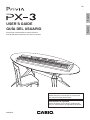
USER’S GUIDE
GUÍA DEL USUARIO
Please keep all information for future reference.
Guarde toda documentación para futuras consultas.
Safety Precautions
Before trying to use the piano, be sure to read
the separate “Safety Precautions”.
Precauciones de seguridad
Antes de intentar usar el piano, asegúrese de
leer las “Precauciones de seguridad” separadas.
PX3ES1A
TO REDUCE THE RISK OF FIRE OR ELECTRIC SHOCK, REFER SERVICING TO QUALIFIED SERVICE PERSONNEL.
IMPORTANT SAFETY INSTRUCTIONS
1.
2.
3.
4.
5.
6.
7.
8.
9.
Read these instructions.
Keep these instructions.
Heed all warnings.
Follow all instructions.
Do not use this apparatus near water.
Clean only with dry cloth.
Do not block any ventilation openings. Install in accordance with the manufacturer’s instructions.
Do not install near any heat sources such as radiators, heat registers, stoves, or other apparatus (including amplifiers) that produce heat.
Do not defeat the safety purpose of the polarized or grounding-type plug. A polarized plug has two blades with one wider than the other.
A grounding type plug has two blades and a third grounding prong. The wide blade or the third prong are provided for your safety. If the
provided plug does not fit into your outlet, consult an electrician for replacement of the obsolete outlet.
10. Protect the power cord from being walked on or pinched particularly at plugs, convenience receptacles, and the point where they exit
from the apparatus.
11. Only use attachments/accessories specified by the manufacturer.
12. Use only with the cart, stand, tripod, bracket, or table specified by the manufacturer, or sold with the
apparatus. When a cart is used, use caution when moving the cart/apparatus combination to avoid injury
from tip-over.
13. Unplug this apparatus during lightning storms or when unused for long periods of time.
14. Refer all servicing to qualified service personnel. Servicing is required when the apparatus has been damaged in any way, such as
power-supply cord or plug is damaged, liquid has been spilled or objects have fallen into the apparatus, the apparatus has been
exposed to rain or moisture, does not operate normally, or has been dropped.
The apparatus shall not be exposed to dripping or splashing and that no objects filled with liquids, such as vases, shall be placed on the apparatus.
The power indicator being unlit does not mean the apparatus is completely disconnected from the MAINS.
When you need to have the apparatus completely disconnected from the MAINS, you must unplug the power cord. For that purpose, locate
the apparatus in a way that secures easy access to the power cord.
Declaration of Conformity
Model Number: PX-3
Trade Name: CASIO COMPUTER CO., LTD.
Responsible party: CASIO AMERICA, INC.
Address: 570 MT. PLEASANT AVENUE, DOVER, NEW JERSEY 07801
Telephone number: 973-361-5400
This device complies with Part 15 of the FCC Rules, Operation is subject to the following two conditions:
(1) This device may not cause harmful interference, and (2) this device must accept any interference received, including interference that
may cause undesired operation.
NOTICE
This equipment has been tested and found to comply with the limits for a Class B digital device, pursuant to Part 15 of the FCC Rules.
These limits are designed to provide reasonable protection against harmful interference in a residential installation. This equipment
generates, uses and can radiate radio frequency energy and, if not installed and used in accordance with the instructions, may cause
harmful interference to radio communications. However, there is no guarantee that interference will not occur in a particular installation. If
this equipment does cause harmful interference to radio or television reception, which can be determined by turning the equipment off and
on, the user is encouraged to try to correct the interference by one or more of the following measures:
• Reorient or relocate the receiving antenna.
• Increase the separation between the equipment and receiver.
• Connect the equipment into an outlet on a circuit different from that to which the receiver is connected.
• Consult the dealer or an experienced radio/TV technician for help.
FCC WARNING
Changes or modifications not expressly approved by the party responsible for compliance could void the user’s authority to operate the
equipment.
Important!
Please note the following important information before using this product.
• Before using the AD-A12150LW Adaptor to power the product, be sure to check the AC Adaptor for any damage first. Carefully check the power
cord for breakage, cuts, exposed wire and other serious damage. Never let children use an AC adaptor that is seriously damaged.
• The product is not intended for children under 3 years.
• Use only the CASIO AD-A12150LW adaptor.
• The AC adaptor is not a toy.
• Be sure to disconnect the AC adaptor before cleaning the product.
This mark applies in EU countries only.
Manufacturer:
CASIO COMPUTER CO.,LTD.
6-2, Hon-machi 1-chome, Shibuya-ku, Tokyo 151-8543, Japan
Responsible within the European Union:
CASIO EUROPE GmbH
Casio-Platz 1, 22848 Norderstedt, Germany
General Guide........................... E-2
Using Registration Memory...E-34
Installing the Music Stand........................................... E-3
PX-3 Configuration ..................................................... E-4
Modes ......................................................................... E-6
Saving Settings and Using Panel Lock....................... E-7
Returning the Digital Piano to Its
Factory Default Settings ............................................. E-7
Registration Data ...................................................... E-34
Registration Memory Operations .............................. E-34
Saving Registration Memory Bank Data to a File ..... E-36
Power Outlet ............................. E-8
Using the Function Menu ......E-38
Function Menu Operations........................................ E-38
Function Menu Settings ............................................ E-39
Using an AC Adaptor .................................................. E-8
Playing Back a MIDI File ........E-41
Connections.............................. E-9
MIDI File Playback Operations.................................. E-41
Supported Operations During MIDI File Playback .... E-42
Creating a New Card Music Folder ........................... E-44
Connecting Headphones ............................................ E-9
Connecting a Pedal .................................................... E-9
Connecting Audio Equipment or an Amplifier ........... E-10
Bundled and Optional Accessories........................... E-10
Using a Memory Card ............E-46
Memory Card Operations.......................................... E-46
Error Messages......................................................... E-48
Selecting and
Playing a Tone ........................ E-11
Connecting to a Computer ....E-49
To turn on Digital Piano Power ................................. E-11
Listening to Demo Tunes.......................................... E-11
Selecting a Tone....................................................... E-11
Layering and Splitting Tones .................................... E-12
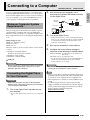
Minimum Computer System Requirements .............. E-49
Connecting the Digital Piano to Your Computer ....... E-49
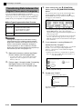
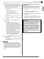
Transferring Data between the
Digital Piano and a Computer ................................... E-50
Applying Effects to a Tone .... E-17
Reference ................................E-52
Reverb and Chorus................................................... E-17
Pitch Bend Wheel ..................................................... E-17
Troubleshooting ........................................................ E-52
Product Specifications............................................... E-54
Operating Precautions .............................................. E-55
Confirming Common
Parameter Settings................. E-18
Common Parameters Operations ............................. E-18
Common Parameter Settings ................................... E-20
Using the Assignable
Buttons.................................... E-24
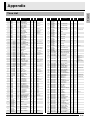
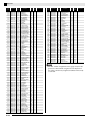
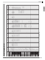
Appendix .................................E-57
Tone List ................................................................... E-57
Drum Assignment List ............................................... E-59
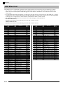
DSP Effect List .......................................................... E-60
DSP Algorithm List .................................................... E-61
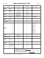
MIDI Implementation Chart
Applying Modulation to Notes (ASSIGNABLE 1) ...... E-24
Applying Portamento to Notes (ASSIGNABLE 1/2) ... E-24
Changing the Rotary Effect Speed
(ASSIGNABLE 2)...................................................... E-24
By-passing the DSP (ASSIGNABLE 2) .................... E-25
Sending Control Changes (ASSIGNABLE 1/2) ........ E-25
Using the Digital Piano as a
MIDI Master Keyboard............ E-26
External MIDI Device Connection............................. E-26
Specifying the Zone Configuration............................ E-26
Specifying What Each Zone Controls ....................... E-27
Zone Setups ............................................................. E-27
Editing Zone Parameters ....... E-28
Zone Parameter Operations ..................................... E-28
Zone Parameter Settings.......................................... E-30
Company and product names used in this
manual may be registered trademarks of others.
E-1
English
Contents
General Guide
8
1
2
3
4
5
6
9
7
bl
bk
bm
bn
bo
bp
∗
bq
do
br
ck
bs
cl
cm
bt
cn
co
cp
cs
ct
cq
cr
dk
dn
dl
dm
Back
dp
dq
dr
Left Side
ds
dt
ek
Bottom
en
el
E-2
em
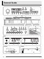
General Guide
VOLUME knob
CLAVI/VIBES, 4 button
ZONE SELECTOR (LOWER 1), REPEAT button
ORGAN, 5 button
ZONE SELECTOR (LOWER 2), sREW button
STRINGS/ENSEMBLE, 6 button
ZONE SELECTOR (UPPER 1), dFF button
GUITAR/BASS, 7 button
ZONE SELECTOR (UPPER 2), PAUSE button
OTHERS/GM, 8 button
INT/EXT, PLAY/STOP button
LAYER, EXIT button
ZONE EDIT, PAGE, PART button
SPLIT, u button
ASSIGNABLE 1 button
REVERB, i button
ASSIGNABLE 2 button
CHORUS, ENTER button
EDIT, TEMPO button
STORE, USB DEVICE MODE button
MASTER CONTROL, CARD PLAYER, LOAD/SAVE
SD CARD SLOT
button
PARAMETER SELECTOR (TRANSPOSE, A) button
PARAMETER SELECTOR (BEND RANGE, B)
button
English
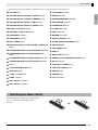
• This manual uses the numbers and names below to refer to buttons and controllers.
PITCH BEND wheel
USB port
MIDI OUT/IN terminals
PARAMETER SELECTOR (BRILLIANCE, C) button
DAMPER, SOFT/SOSTENUTO PEDAL jacks
PARAMETER SELECTOR (EQ ON/OFF, D) button
DC 12V terminal
Display
LINE OUT R, L/MONO jacks
TONE, REGISTRATION button
LINE IN R, L/MONO jacks
FUNCTION button
POWER button
w/NO, q/YES button
PHONES jacks
PIANO, 1 button
Pedal connector
ELEC PIANO 1, 2 button
ELEC PIANO 2, 3 button
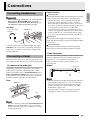
* Installing the Music Stand
Insert the bottom of the music stand into the
groove on the top of the Digital Piano’s
console.
E-3
General Guide
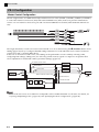
PX-3 Configuration
Master Control Configuration
The PX-3 Digital Piano is a MIDI master keyboard that uses four zones (UPPER 1, UPPER 2, LOWER 1, LOWER 2)
to control the internal sound source (INT) and external MIDI devices (EXT). Each zone performs simultaneous
control over one internal sound source part and one external MIDI device channel (when both INT and EXT are
ON).
The target (INT/EXT) of each zone control can be turned on or off as desired using the (INT/EXT) button. Zone
editing (page E-28) lets you configure detailed settings related to how each individual zone controls an internal
sound source and/or external MIDI device.
In the case of an internal sound source, zone editing can be performed to create sounds by selecting a DSP,
configuring DSP settings, editing tones, etc. Following sound creation, signals are output via an equalizer that
allows adjustment of centralized common parameter settings (page E-18).
Acoustic Resonance Send
ACOUSTIC
RESONANCE
Reverb Send
REVERB
Chorus Send
Part
WAVE
GENERATOR
CHORUS
Thru
EQUALIZER
DSP
DSP Acoustic Resonance Send
DSP Reverb Send
DSP
X 36
EFFECT
1
EFFECT
2
EFFECT
3
DSP Bypass
Output
DSP Chorus Send
X2
NOTE
• Which of the four zones are available for use depends on the LAYER and SPLIT on/off status. For details, see
“Layering and Splitting Tones” (page E-12) and “Specifying the Zone Configuration” (page E-26).
E-4
General Guide
Sound Source Configuration
English
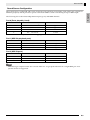
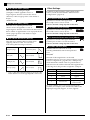
The sound source is configured with a total of 36 parts: four parts that correspond to each of the zones, 16 parts for
MIDI file playback, and 16 parts that operate as the multi-timbre sound source during receipt of MIDI input.
The following shows the relationships between parts, ports, and MIDI channels.
Port 0 (Parts played by hand)
Part Number
MIDI Channel
Part Name
1
IN:- - / OUT:01-16*1
Upper1
2
IN:- - / OUT:01-16*1
Upper2
3
IN:- - / OUT:01-16*1
Lower1
4
IN:- - / OUT:01-16*1
Lower2
*1 MIDI OUT channel depends on zone editing (page E-28).
Port 1 (MIDI file playback parts)
Part Number
MIDI Channel
Part Name
17
IN:- - / OUT:01
Song01
...
...
...
32
IN:- - / OUT:16
Song16
Part Number
MIDI Channel
Part Name
33
IN:01 / OUT:- -
Ext.01
Port 2 (MIDI IN parts)
...
...
...
48
IN:16 / OUT:- -
Ext.16
NOTE
• MIDI messages output from the above Port 0 and Port 1 are grouped and sent from a single MIDI port. Portspecific send is not supported.
E-5
General Guide
Modes
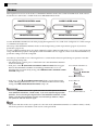
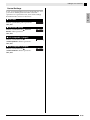
This Digital Piano has two main modes: a MASTER CONTROL mode and a CARD PLAYER mode. Each of these
modes has two sub-modes: a TONE mode and a REGISTRATION mode.
MASTER CONTROL mode
CARD PLAYER mode
TONE mode
TONE mode
REGISTRATION mode
REGISTRATION mode
Use the MASTER CONTROL mode when playing the Digital Piano in a stand-alone configuration or when using it
as a MIDI master keyboard.
The setup of the MASTER CONTROL mode can be changed using common parameters (page E-18) and zone
parameters (page E-28).
Use the CARD PLAYER mode to play back a MIDI file. In the CARD PLAYER mode, you can play on the keyboard
along with MIDI file playback. Though the CARD PLAYER mode also supports control of an external MIDI device,
parameter settings cannot be configured.
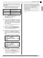
Note that you should be aware of the Digital Piano’s current mode whenever performing an operation. Note the
following important points.
• The Digital Piano’s initial power on default mode is the MASTER CONTROL
mode’s TONE mode.
• Each press of the (MASTER CONTROL/CARD PLAYER) button toggles
Lit in the MASTER CONTROL mode.
between the MASTER CONTROL and CARD PLAYER modes. You can
determine the current mode by noting which (MASTER CONTROL/CARD
PLAYER) lamp is lit.
Lit in the CARD PLAYER mode.
• Each press of the (TONE/REGISTRATION) button toggles between the
TONE and REGISTRATION modes. You can determine the current mode by
noting which (TONE/REGISTRATION) lamp is lit.
Lit in the TONE mode.
IMPORTANT!
• All of the operations in this user’s guide start from the initial power on default
state (MASTER CONTROL, TONE mode). If you start experiencing operation
problems, first try returning the Digital Piano to the MASTER CONTROL, TONE
mode. If you do not mind losing currently unsaved settings and data, simply
turn power off and then back on again.
Lit in the REGISTRATION mode.
NOTE
• The section title bars in this user’s guide also show the mode (MASTER CONTROL or CARD PLAYER, or both)
where the operations described in each section can be performed.
E-6
General Guide
English
Saving Settings and Using
Panel Lock
Your Digital Piano lets you save its current settings,
and lock its buttons to protect against operation errors.
For details, see “Backup” and “Panel Lock” (page
E-40).
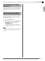
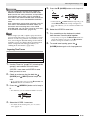
Returning the Digital Piano to
Its Factory Default Settings
Perform the following procedure when you want to
return the Digital Piano’s stored data and settings to
their initial factory defaults.
1.
2.
Turn off the Digital Piano.
While holding down both the (TONE) and
(FUNCTION) buttons, press the
(POWER) button.
• The Digital Piano will turn on and initialize its
internal system. You will be able to use the Digital
Piano in a short while.
NOTE
• See “To turn on Digital Piano Power” (page E-11) for
information about turning Digital Piano power on
and off.
E-7
Power Outlet
Your Digital Piano runs on standard household power.
Be sure to turn off power whenever you are not using
the Digital Piano.
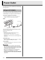
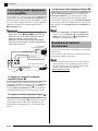
Using an AC Adaptor
Use only the AC adaptor (JEITA Standard, with unified
polarity plug) that comes with this Digital Piano. Use of
a different type of AC adaptor can cause malfunction.
Specified AC Adaptor: AD-A12150LW
• Use the supplied power cord to connect the AC
adaptor as shown in the illustration below.
Back
Household power
Power cord
DC 12V terminal
AC adaptor
Note the following important precautions to avoid
damage to the power cord.
During Use
• Never pull on the cord with excessive force.
• Never repeatedly pull on the cord.
• Never twist the cord at the base of the plug or
connector.
• The power cord should not be stretched tight while
it is in use.
During Movement
• Before moving the Digital Piano, be sure to unplug
the AC adaptor from the power outlet.
During Storage
• Loop and bundle the power cord, but never wind it
around the AC adaptor.
IMPORTANT!
• Never connect the AC adaptor (JEITA Standard,
with unified polarity plug) that comes with this Digital
Piano to any other device besides this piano. Doing
so creates the risk of malfunction.
• Make sure the Digital Piano is turned off before
plugging in or unplugging the AC adaptor.
• The AC adaptor will become warm to the touch after
very long use. This is normal and does not indicate
malfunction.
E-8
Connections
IMPORTANT!
• Before connecting headphones, be sure to use the
Digital Piano’s (VOLUME) knob to turn the
volume down to a low level. After connecting, you
can adjust the volume to the level you want.
Left Side
Commercially available
headphones
PHONES jacks
Damper Pedal
Pressing the damper pedal while playing will cause the
notes you play to reverberate for a very long time.
• Whenever a piano tone is selected, pressing this
pedal will activate the Digital Piano’s Acoustic
Resonance effect, which causes notes to resonate in
the same way they do when the damper pedal on an
acoustic piano is pressed. You can adjust the
acoustic resonance effect for each individual tone,
and you can apply it to other non-piano tones, if you
want. For details, see “Acoustic Resonance” (page
E-39) and “Acoustic Resonance Send” (page E-32).
Soft Pedal
Pressing this pedal suppresses notes played on the
keyboard after the pedal was pressed, and makes them
sound softer.
Mini plug
Connect commercially available headphones to the
PHONES jacks. To protect your hearing, make sure
that you do not set the volume level too high when
using headphones.
Connecting a Pedal
The back of the Digital Piano has two pedal jacks, one
for a damper pedal and one for a soft/sostenuto pedal.
To connect to the pedal jack
Sostenuto Pedal
Only the notes that are played while this pedal are
depressed are sustained until the pedal is released.
Pedal Connector
You can connect the optionally available 3-Pedal Unit
(SP-32) to the pedal connector on the bottom of the
Digital Piano. You can then use the pedals for
expression that is similar to that available on an
acoustic piano.
Bottom
Depending on the type of operation you want the
pedal (SP-3) to perform, connect the pedal’s cable
either to the Digital Piano’s DAMPER PEDAL jack or
SOFT/SOSTENUTO PEDAL jack. If you want to use
both operations (jacks) at the same time, you need to
purchase another optionally available pedal.
Back
Pedal connector
NOTE
• The SP-32 Pedal Unit supports half-pedal operation
(pressing the pedal part way). You can adjust the
amount of the effect is applied when the damper
pedal is pressed part way. For details, see “Half
Pedal Effect” (page E-39).
• The optionally available CS-67P special stand is
required in order to use the SP-32 Pedal Unit.
PEDAL jacks
SP-3
NOTE
• You can connect a pedal to the SOFT/SOSTENUTO
PEDAL jack and apply either a soft or sostenuto
effect to the notes you play. For details, see “Pedal
Assign” (page E-39).
E-9
English
Pedal Functions
Connecting Headphones
Connections
Connecting Audio Equipment
or an Amplifier
This Digital Piano outputs notes from its LINE OUT R
(right channel output) and LINE OUT L/MONO (left
channel output). Connect a keyboard amplifier or other
device to direct output to speakers. You can adjust the
LINE OUT volume level with the Digital Piano’s
(VOLUME) knob.
To input from audio equipment (Figure )
LINE IN R jack input is output from the LINE OUT R
jack, and LINE IN L/MONO input is output from
LINE OUT L/MONO. Use commercially available
connection cords that match the equipment being
connected to. Connecting a cord to LINE IN L/MONO
only will cause the left and right channels to be mixed
and output from both LINE OUT R and LINE OUT L/
MONO.
NOTE
IMPORTANT!
• Whenever connecting something to the Digital
Piano, first use the (VOLUME) knob to set the
volume to a low level. After connecting, you can
adjust the volume to the level you want.
• Whenever you connect any device to the Digital
Piano, be sure to read the user documentation that
comes with the device.
Guitar amplifier
Keyboard amplifier, etc.
INPUT 1
Standard plug
INPUT 2
Tape recorder,
MIDI sound source, etc.
• Input from LINE IN R and LINE IN L/MONO is
output as-is from LINE OUT R and LINE OUT L/
MONO. The Digital Piano’s (VOLUME) knob
setting does not affect this output.
Bundled and Optional
Accessories
Use only accessories that are specified for use with this
Digital Piano.
Use of unauthorized accessories creates the risk of fire,
electric shock, and personal injury.
NOTE
Standard jack
Audio amplifier AUX IN jack, etc.
LEFT (White)
RIGHT (Red)
Pin plug
To output to a musical instrument
amplifier (Figure )
Use a commercially available connecting cord to
connect the amplifier to the Digital Piano’s LINE OUT
L/MONO jack as shown in Figure . Connecting a
cord to LINE OUT L/MONO only will cause the left
and right channels to be mixed and output as mono.
To output to audio equipment (Figure )
Use commercially available connection cords to
connect as shown in Figure . Normally, you should
set the input selector of the audio equipment to the
terminal where the Digital Piano is connected (AUX
IN, etc.).
E-10
• You can get information about accessories that are
sold separately for this product from the CASIO
catalog available from your retailer, and from the
CASIO website at the following URL.
http://world.casio.com/
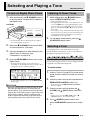
Selecting and Playing a Tone
To turn on Digital Piano Power
1.
After ensuring that the (POWER) button is
in the off position, connect the AC adaptor to
the Digital Piano.
Listening to Demo Tunes
1.
• This starts demo tune play.
• The Digital Piano has a total of four demo tunes. You
can use the buttons to jump the beginning of the
previous (q) or next (w) demo tune. You can use
the Tone Group buttons ( to ) to select a specific
demo tune.
• You can play along on the keyboard with demo tune
play. Note, however, that you cannot change the tone
assigned to the keyboard. Only the key operations
described above are supported.
Left Side
Off position
On position
button
2.
• For information about connecting the AC adaptor,
see “Power Outlet” (page E-8).
2.
Rotate the (VOLUME) knob towards MIN
to set the volume to a low level.
3.
Connect headphones or other devices to the
Digital Piano as necessary (see
“Connections” on page E-9).
4.
Press the (POWER) button to turn on the
Digital Piano.
• The Digital Piano display screen will appear as
shown below, which indicates that it is ready to play
(using initial power on default settings).
• To turn off the Digital Piano, press the (POWER)
button again.
To stop demo tune playback, press the
(PLAY/STOP) button again.
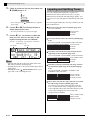
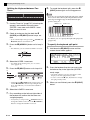
Selecting a Tone
Your Digital Piano comes with 250 tones (which
include 10 drum sets) built in. Tones are divided into
the eight tone groups shown below.
Use the following procedure to select a single tone that
is applied across the entire keyboard.
To select a tone
1.
Use the “Tone List” (page E-57) to look up the
group and the number of the tone you want to
select.
2.
Check to make sure that the lamp above the
(MASTER CONTROL) button is lit.
• If it is unlit, press the (MASTER CONTROL)
IMPORTANT!
• Normally, turning power off and then back on again
will return the Digital Piano to its initial power on
default settings. If you perform the backup operation
(page E-40), turning power back on again will restore
the backed up settings. Perform a backup (page
E-40) or registration operation (page E-34) to save
the keyboard setup if you need to restore it later.
While holding down the (PART) button,
press the (PLAY/STOP) button.
button to light it.
3.
Check to make sure that the both the
(LAYER) and (SPLIT) button lamps are
unlit.
• If they are lit, press the (LAYER) and/or
(SPLIT) buttons to turn off both lamps.
4.
If the (UPPER 1) button lamp is unlit,
press the (UPPER 1) button so its lamp is
lit.
E-11
English
MASTER CONTROL
Selecting and Playing a Tone
5.
Check to make sure that the lamp above the
(TONE) button is lit.
You can configure the keyboard so it plays two
different tones at the same time (Layer) or to play
different tones in the left and right ranges (Split). You
can even use Layer and Split in combination with each
other.
Lit
6.
Layering and Splitting Tones
• If it is unlit, press the (TONE) button to light the
upper lamp.
The following describes the various possible Layer and
Split combinations.
Use the to (Tone Group) buttons to
select the group you want.
One tone across the entire keyboard (page E-11)
Use zone UPPER 1.
UPPER 1 INT ON
• The lamp of the button you press will light.
LAYER OFF
7.
Use the (w, q) buttons to select the
tone you want. Now you can play on the
keyboard using the tone you selected.
Example: To select the “Jazz Organ 2” tone in the
“ORGAN” group
UPPER 1
SPLIT OFF
Two layered tones across the entire keyboard (page
E-13)
Use zones UPPER 1 and UPPER 2 at the same time.
UPPER 1/2 INT ON
Tone number
Tone name
LAYER ON
UPPER 1
UPPER 2
SPLIT OFF
Two tones, one for the left range and one for the
right range of the keyboard (page E-14)
Use zones UPPER 1 and LOWER 1 at the same time.
UPPER 1/LOWER 1 INT ON
LAYER OFF
NOTE
• Pressing w and q at the same time selects tone
001 in the currently selected group.
• Holding down w or q will scroll through tones at
high speed.
• Holding down the (FUNCTION) button as you
press w or q will jump 10 tones.
LOWER 1
UPPER 1
SPLIT ON
Four tones, two layered for the left range and two
layered for the right range of the keyboard (page
E-15)
Use zones UPPER 1, UPPER 2, LOWER 1, and
LOWER 2 at the same time.
UPPER 1/2 INT ON
LOWER 1/2 INT ON
LOWER 1
LOWER 2
UPPER 1
UPPER 2
LAYER ON, SPLIT ON
Three tones, one for one range and two layered for
the other range of the keyboard (page E-16)
Use all four zones at the same time, but with one
zone’s sound turned off by configuring one of the
zones with INT OFF to disconnect the internal sound
source. The example below shows INT OFF
configured for LOWER 2.
UPPER 1/2, LOWER 1 INT ON
LOWER 2 INT OFF
LOWER 1
E-12
UPPER 1
UPPER 2
LAYER ON, SPLIT ON
Selecting and Playing a Tone
5.
• You can select a tone for each zone in both the
MASTER CONTROL and CARD PLAYER modes.
Note however that some procedures and operations
(lamp lighting status) when a tone is selected for
each zone in the CARD PLAYER mode are different
from those in the case of the MASTER CONTROL
mode.
Here, explanations are based on selecting a tone for
each zone in the MASTER CONTROL mode. For
information about selecting tones in the CARD
PLAYER mode, see “To select a tone for each zone
in the CARD PLAYER mode” (page E-44).
NOTE
• When using Layer and/or Split to play more than
one tone at the same time, you can adjust the volume
balance of each zone, perform octave shift for each
zone, and configure detailed settings for the effects
applied to zones. For details about parameters that
can be configured and setting procedures, see
“Editing Zone Parameters” (page E-28).
Press the (LAYER) button so its lamp is lit.
Lit
Unlit
English
IMPORTANT!
Lit
• At this time the (UPPER 1) button lamp will go out
and the (UPPER 2) button lamp will light in its
place. This indicates you can select the UPPER 2 zone
tone.
6.
7.
Select the UPPER 2 zone tone.
Play something on the keyboard to check
how the tones sound layered together.
• At any time you can press the (UPPER 1) button to
change the UPPER 1 zone tone or the (UPPER 2)
button to change the UPPER 2 zone tone.
8.
To cancel tone layering, press the
(LAYER) button again so its lamp goes out.
Layering Two Tones
UPPER 1
UPPER 2
1.
Use the “Tone List” (page E-57) to look up the
group(s) and numbers of the two tones
(UPPER 1 zone tone and UPPER 2 zone
tone) you want to use.
2.
Check to make sure that the both the
(LAYER) and (SPLIT) button lamps are
unlit.
• If one or both lamps are lit, press the (LAYER) and
(SPLIT) buttons to turn them off.
3.
Press the (UPPER 1) button so its lamp is
lit.
• This indicates you can select the UPPER 1 zone tone.
Lit
4.
Select the UPPER 1 zone tone.
• For details about selecting tones, see “To select a
tone” (page E-11).
E-13
Selecting and Playing a Tone
Splitting the Keyboard between Two
Tones
8.
To cancel the keyboard split, press the
(SPLIT) button again so its lamp goes out.
NOTE
LOWER 1
UPPER 1
1.
Use the “Tone List” (page E-57) to look up the
group(s) and numbers of the two tones
(UPPER 1 zone tone and LOWER 1 zone
tone) you want to use.
2.
Check to make sure that the both the
(LAYER) and (SPLIT) button lamps are
unlit.
• If one or both lamps are lit, press the (LAYER) and
(SPLIT) buttons to turn them off.
3.
Press the (UPPER 1) button so its lamp is
lit.
• This indicates you can select the UPPER 1 zone tone.
• You also can specify the keyboard split point, which
the location where the keyboard splits between the
left range and right range. In initial default split
point is at key F#3.
LOWER 1 zone
UPPER 1 zone
Split point
For details, see “To specify the keyboard split point”
(page E-14).
To specify the keyboard split point
1.
Hold down the (SPLIT) button until the
screen shown below appears.
Lit
4.
Select the UPPER 1 zone tone.
• For details about selecting tones, see “To select a
tone” (page E-11).
5.
Press the (SPLIT) button so its lamp is lit.
Current split point key name
2.
Lit
Lit
6.
7.
Select the LOWER 1 zone tone.
Play something on the left and right sides of
the keyboard to confirm that the tones are
assigned properly.
• At any time you can press the (UPPER 1) button to
change the UPPER 1 zone tone or the (LOWER 1)
button to change the LOWER 1 zone tone.
E-14
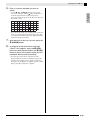
• The name of the key you press will appear on the
display as the new split point key name.
• You also can use the (w, q) buttons to change
the split point key name.
Unlit
• At this time the (UPPER 1) button lamp will go out
and the (LOWER 1) button lamp will light in its
place. This indicates you can select the LOWER 1
zone tone.
Press the keyboard key that you want to be
the leftmost key in the right side (UPPER 1
zone) range.
3.
When you are finished, press the (SPLIT)
button.
To use layer and split together
LOWER 1
LOWER 2
1.
2.
3.
UPPER 1
UPPER 2
Use the “Tone List” (page E-57) to look up the
group(s) and numbers of the tones (UPPER 1,
UPPER 2, LOWER 1, and LOWER 2 zone
tones) you want to use.
Check to make sure that the both the
(LAYER) and (SPLIT) button lamps are
unlit.
• If one or both lamps are lit, press the (LAYER) and
(SPLIT) buttons to turn them off.
7.
Press the (LAYER) button so its lamp is
unlit.
8.
Press the (SPLIT) button so its lamp is lit.
Lit
Lit
• This will cause the (LOWER 1) button lamp to
light. This indicates you can select the LOWER 1 zone
tone.
9. Select the LOWER 1 zone tone.
10. Press the (LAYER) button so its lamp is lit.
Lit
Press the (UPPER 1) button so its lamp is
lit.
• This indicates you can select the UPPER 1 zone tone.
Lit
• This will cause the (LOWER 2) button lamp to
light. This indicates you can select the LOWER 2 zone
tone.
11. Select the LOWER 2 zone tone.
12. Play something on the left and right sides of
Lit
4.
5.
Select the UPPER 1 zone tone.
• For details about selecting tones, see “To select a
tone” (page E-11).
the keyboard to confirm that the tones are
assigned and layered properly.
Press the (LAYER) button so its lamp is lit.
• You can change any of the zone tones at any time by
performing one of the operations shown below.
Lit
To change this
zone’s tone:
UPPER 1 zone
Press the (UPPER 1) button and
then select a tone.
UPPER 2 zone
• This will cause the (UPPER 2) button lamp to
light. This indicates you can select the UPPER 2 zone
tone.
Press the (UPPER 2) button and
then select a tone.
LOWER 1 zone
Press the (LOWER 1) button and
then select a tone.
Select the UPPER 2 zone tone.
LOWER 2 zone
Press the (LOWER 2) button and
then select a tone.
Unlit
6.
Do this:
Lit
E-15
English
Selecting and Playing a Tone
Selecting and Playing a Tone
13. To cancel layer and split, press (LAYER)
and (SPLIT) buttons again so their lamps
go out.
NOTE
• When using Layer and Split at the same time, you
can switch to only a single tone in either of the
keyboard ranges by configuring INT OFF for the
zone whose tone you do not want to sound. For
example, you could perform the steps below to
sound zones UPPER 1, UPPER 2, and LOWER 1,
without sounding the LOWER 2 zone.
UPPER 1
UPPER 2
LOWER 1
1. Press the (LOWER 2) button so its lamp is lit.
2. Press the (INT/EXT) button twice so the INT
side (left side) lamp goes out.
Unlit
Lit
• Pressing the (UPPER 1), (UPPER 2),
(LOWER 1) or (LOWER 2) button causes the
lamp of the pressed button to light, and the lamps of
the other buttons to go out. At this time, the tone
name of the zone whose button you press will
appear on the display, and you can change the tone,
if you want. However, the tones that sound when a
keyboard keys are pressed depend on the current
Layer and Split on/off settings.
• The (INT/EXT) button is for specifying what each
zone controls (INT = internal sound source, EXT =
external MIDI device). The INT (left) side lamp
indicates internal sound source control on/off, while
the EXT (right) side indicates external MIDI device
control on/off. For details about this button, see
“Using the Digital Piano as a MIDI Master
Keyboard” (page E-26).
E-16
Applying Effects to a Tone
MASTER CONTROL
Your Digital Piano provides four types of reverb and
four types of chorus. The reverb and chorus functions
have their own dedicated keys for easy on/off
operation.
• Each press of the (REVERB) button toggles
reverb on and off. The lamp above the button is lit
when reverb is on, and unlit when it is off.
• Each press of the (CHORUS) button toggles
chorus on and off. The lamp above the button is lit
when chorus is on, and unlit when it is off.
To change the chorus type
1.
Hold down the (CHORUS) button until the
screen shown below appears.
2.
Use the (w, q) buttons to select the
chorus type you want.
• You can select one of the following chorus types:
Light Chorus, Chorus, Deep Chorus,
Flanger.
IMPORTANT!
• Under initial default settings of certain tones, chorus
is not applied simply by turning chorus on. This is
because the initial default value of the chorus send
setting is 0. To apply chorus, change the chorus
send value of the zone where you want to use it. For
details, see “Effect Settings” (page E-32).
NOTE
• The reverb and chorus on/off setting is applied to all
zones, but reverb send and chorus send settings can
be configured for individual zones. For details, see
“Effect Settings” (page E-32).
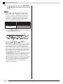
To change the reverb type
1.
3.
When you are finished, press the
(CHORUS) button.
Pitch Bend Wheel
The (PITCH BEND) wheel lets you
change the pitch of notes you are playing
by rotating the wheel forward or back.
Rotating the wheel away from you raises
the pitch, while rotating it towards you
lowers it. Releasing the wheel causes the
pitch of the notes to return to normal
automatically.
IMPORTANT!
Hold down the (REVERB) button until the
screen shown below appears.
• Do not have the pitch bend wheel rotated as you turn
on the Digital Piano.
NOTE
• You also can change the range of the pitch bend
wheel. See “Bend Range” (page E-20).
2.
Use the (w, q) buttons to select the
reverb type you want.
• You can select one of the following reverb types:
Room, Hall, Large Hall, Stadium.
3.
When you are finished, press the
(REVERB) button.
E-17
English
Reverb and Chorus
CARD PLAYER
Confirming Common Parameter Settings
MASTER CONTROL
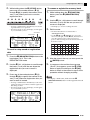
Common parameters include transpose, bend range, equalizer, and other global parameters. Common parameters
also include the settings of the function assigned to the ASSIGNABLE buttons.
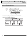
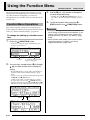
Common Parameters Operations
The common parameter settings appear on the common menu that appears first whenever you turn on the Digital
Piano.
Page
Parameter Name
Common menu
Settings
• The common menu has five pages. Press the (PAGE) button to scroll through the pages.
• Each common menu page includes up to four parameters, each of which corresponds one of the PARAMETER
SELECTOR buttons ( (A) through (D)).
• The “COMMON PARAMETER” list in the upper left of the Digital Piano’s control panel shows the parameters
assigned to each of the PARAMETER SELECTOR buttons.
E-18
Confirming Common Parameter Settings
1.
5.
Check to make sure that the lamp above the
(MASTER CONTROL) button is lit.
• If it is unlit, press the (MASTER CONTROL)
• Pressing w and q at the same time returns the
setting to its initial default.
• Holding down w or q will scroll through the
settings at high speed.
• For details about the meaning and range of each
parameter setting, see “Common Parameter Settings”
(page E-20).
button to light it.
Lit
6.
2.
Check to make sure that the lamp above the
(ZONE EDIT) button is unlit.
• If the lamp is lit, hold down the (ZONE EDIT)
button until it goes out.
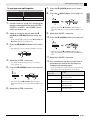
3.
Use the (PAGE) button to display the
common menu page that contains the
parameter whose setting you want to change.
Example: Common menu page 2
Use the (EDIT w, q) buttons to change
the setting.
If you want to change the settings of other
parameters, repeat steps 3 through 5 of this
procedure.
IMPORTANT!
Turning off the Digital Piano causes all common
parameters to return to their initial default settings. If
you need to save a common parameter setup, perform
one of the operations described below.
• If you want to restore the current setup the next time
you turn on the Digital Piano, perform the backup
operation. For details, see “Backup” (page E-40).
• If you don’t need to restore the current setup the next
time you turn on the Digital Piano but want to have it
on hand for recall when you need it, save the setup
to registration memory. For details, see “Using
Registration Memory” (page E-34).
• Each press of the (PAGE) button advances to the
next page.
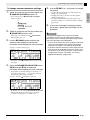
4.
Press the PARAMETER SELECTOR button
( (A) through (D)) to select the
parameter whose setting you want to change.
• The brackets around the setting of parameter you
select will change from [ ] to %. This indicates
that editing of the setting is enabled.
Example: After the (C) button is pressed
• Holding down one of the PARAMETER SELECTOR
buttons will display its full name. For example,
“LoMdG” will change to “LowMid Gain”.
E-19
English
To change common parameter settings
Confirming Common Parameter Settings
Common Parameter Settings
This section explains the meaning of each common parameter, and provides information about their setting ranges
and initial default values.
• In this section, each parameter is preceded by a number and a letter, like “1-A”. This indicates the common menu
page number (1) and the PARAMETER SELECTOR button you need to press to select it (A).
• The values following the description of a parameter are its setting range. The initial default setting is indicated by
an asterisk (*).
General Settings
■ 1-A Transpose (Trnsp)
Adjusts overall keyboard tuning by semitone units
–12 to 0* to 12 semitones
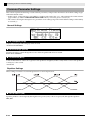
■ 1-B Bend Range (BendR)
Specifies the range of pitch change that occurs when the pitch bend wheel is rotated.
0 to 2* to 12 semitones
■ 1-C Brilliance (Brila)
Controls the brilliance of the tone. A greater value produces a brighter, harder sound, while a lower value produces
a mellower, softer sound.
–3 to 0* to 3
Equalizer Settings
These settings constitute a four-band equalizer for sound compensation.
■ 1-D EQ ON/OFF (EQ)
Specifies whether sound output by the Digital Piano passes (ON) or does not pass (Off) through the equalizer.
OFF, ON*
E-20
Confirming Common Parameter Settings
English
■ 2-A to 3-D Band Gain and Frequency Settings
Parameter Name
Location
Description
Settings (* indicates default)
Low Gain (LoG)
2-A
Adjusts the low-range gain.
–12 to 0* to 12
Low Freq. (LoF)
2-B
Specifies the frequency of the low-range
adjusted by Low Gain.
0.2*, 0.4, 0.8 kHz
LowMid Gain
(LoMdG)
2-C
Adjusts the low mid-range gain.
–12 to 0* to 12
LowMid Freq.
(LoMdF)
2-D
Specifies the frequency of the low midrange adjusted by LowMid Gain.
1.0*, 1.3, 1.6, 2.0, 2.5, 3.2, 4.0, 5.0 kHz
HighMid Gain
(HiMdG)
3-A
Adjusts the high mid-range gain.
–12 to 0* to 12
HighMid Freq.
(HiMdF)
3-B
Specifies the frequency of the high midrange adjusted by HighMid Gain.
1.0, 1.3, 1.6, 2.0, 2.5*, 3.2, 4.0, 5.0 kHz
High Gain (HiG)
3-C
Adjusts the high gain.
–12 to 0* to 12
High Freq. (HiF)
3-D
Specifies the frequency of the high-range
adjusted by High Gain.
6.0, 8.0, 10* kHz
Assignable Button Settings
These settings specify the functions assigned to the (ASSIGNABLE 1) and (ASSIGNABLE 2) buttons.
Functions that can be assigned to each button are shown in the “ASSIGNABLE 1 TYPE” and “ASSIGNABLE 2
TYPE” lists on the control panel to the left of the ASSIGNABLE buttons.
NOTE
• Regardless of the settings you configure for the (ASSIGNABLE 1) and (ASSIGNABLE 2) buttons here, you
can use the zone editing procedure (page E-28) to enable or disable each individual zone. For details, see “Control
Settings” (page E-33).
E-21
Confirming Common Parameter Settings
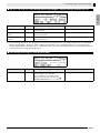
■ 4-A Assignable Button 1 Type (Asgn1)
Specifies the function assigned to the (ASSIGNABLE 1) button.
The following describes the functions that can be assigned by each setting.
Setting
Assigned Functions
Modulation (Mod)
This setting assigns modulation to the button.*1 The depth of the modulation is specified using the
(B) and (C) buttons.
Portamento (Por)
This setting assigns portamento the button. When this function is assigned, portamento is applied
while the (ASSIGNABLE 1) button is depressed and not applied while the button is released.*2
Control Change
Number 0 to 127
(CC# 000 to 127)
This setting assigns a control change number to the button. The MIDI channel for sending a control
change or the value sent when the (ASSIGNABLE 1) button is pressed or released is specified
using the (B), (C), and (D) buttons.
*1 To apply modulation only to a particular zone, select “001” (CC#1 = Modulation) as the Asgn1 instead of “Mod”.
Also, specify a control change send MIDI channel that matches the MIDI channel of the zone where you want to
apply modulation. For more information, see “Settings when Asgn1/Asgn2 = Control Change Number 0 to 127”
(page E-23).
*2 Portamento can be turned on or off for each zone. For details, see “Editing Tones” (page E-31).
■ 5-A Assignable Button 2 Type (Asgn2)
Specifies the function assigned to the (ASSIGNABLE 2) button.
The following describes the functions that can be assigned by each setting.
Settings
Assigned Functions
Rotary (Rot)
This function, which switches rotation speed, can be assigned for the rotary effect used by the DSP
(see “DSP Type” on page E-30). The speed is “Fast” when the (ASSIGNABLE 2) button is on
(lamp lit) and “Slow” when it is off (lamp unlit).
Portamento (Por)
This setting assigns portamento to the button. Portamento is applied when the (ASSIGNABLE 2)
button is on, and not applied when it is off.*1
DSP Bypass (Dbp)
This setting assigns a function that turns off the DSP of a particular zone. The zone whose DSP is
being turned off is specified with the (B) button.
Control Change
Number 0 to 127
(CC# 000 to 127)
This setting assigns a control change number to the button. The MIDI channel for sending a control
change or the value sent when the (ASSIGNABLE 2) button is on or off is specified using the
(B), (C), and (D) buttons.
*1 Portamento can be turned on or off for each zone. For details, see “Editing Tones” (page E-31).
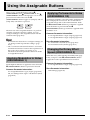
■ 4-B, 4-C Settings when Asgn1 = Modulation (Mod)
Parameter Name
Location
Description
Settings (* indicates default)
Depth (Button OFF)
(OfDep)
4-B
Specifies the modulation depth while the
button is not pressed.
0*
Depth (Button ON)
(OnDep)
4-C
Specifies the modulation depth while the
button is pressed.
0 to 127*
E-22
to 127
Confirming Common Parameter Settings
English
■ 4-B, 4-C, 4-D, 5-B, 5-C, 5-D Settings when Asgn1/Asgn2 = Control Change Number 0 to 127
Parameter Name
Location
Description
Settings (* indicates default)
Channel (Ch)
4-B, 5-B
Specifies the MIDI channel*1 for sending
control changes.
1* to 16
Value (Button OFF)
(OfVal)
4-C, 5-C
Specifies the value sent when the button is
released (turned off).
0* to 127
Value (Button ON)
(OnVal)
4-D, 5-D
Specifies the value sent when the button is
pressed (turned on).
0* to 127
*1 Control change information in principle is sent from the Digital Piano to an external destination over the MIDI
channel specified here. However, when a MIDI send channel of one of the Digital Piano’s zones matches the
channel specified here and that zone is configured as INT ON, control change information is sent for the internal
sound source that corresponds to that zone.
■ 5-B Settings when Asgn2 = DSP Bypass (Dbp)
Parameter Name
Zone
Location
5-B
Description
This setting can be used to select the zone
(Up1: UPPER 1, Up2: UPPER 2,
Lo1: LOWER 1, Lo2: LOWER 2) that
bypasses the DSP (DSP off) when the
(ASSIGNABLE 2) button is on (lamp lit).
Settings (* indicates default)
Up1*,
Up2, Lo1, Lo2
E-23
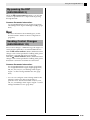
Using the Assignable Buttons
MASTER CONTROL
There are two assignable buttons named
(ASSIGNABLE 1) and (ASSIGNABLE 2). The
(ASSIGNABLE 1) button is designed so it is on while
pressed and off while released. The
(ASSIGNABLE 2) button toggles on (lamp lit) and off
(lamp unlit) each time it is pressed.
The main use of the assignable buttons is to perform
real-time operations, mainly for effects. You can
configure settings for the assignable button with the
common menu (page E-18).
CARD PLAYER
Applying Portamento to Notes
(ASSIGNABLE 1/2)
Applying portamento causes the pitch to slide between
two notes played in succession. It is an effect that is
used with strings and woodwind instruments. With
the (ASSIGNABLE 1) button, portamento is applied
while the button is pressed. With the
(ASSIGNABLE 2) button, portamento is applied while
the button is on.
Common Parameter Information:
4-A Assignable Button 1 Type (Asgn1) (page E-22)
5-A Assignable Button 2 Type (Asgn2) (page E-22)
NOTE
• For information about how to configure settings, see
“To change common parameter settings” (page
E-19).
• The “Common Parameter Information” and “Zone
Parameter Information” items in the explanations in
this section show where you need to go for
information about the parameters that come under
an assignable function.
Applying Modulation to Notes
(ASSIGNABLE 1)
Fixed-depth modulation is applied to notes while the
(ASSIGNABLE 1) button is pressed or released.
Common Parameter Information:
4-A Assignable Button 1 Type (Asgn1) (page E-22)
4-B, 4-C Settings when Asgn1 = Modulation (Mod)
(page E-22)
E-24
Zone Parameter Information:
4-C Portamento ON/OFF (Porta) (page E-31)
4-D Portamento Time (PTime) (page E-31)
Changing the Rotary Effect
Speed (ASSIGNABLE 2)
When the rotary effect is being selected by DSP (page
E-30), each press of the (ASSIGNABLE 2) button
toggles the rotation speed between fast and slow.
Common Parameter Information:
5-A Assignable Button 2 Type (Asgn2) (page E-22)
Zone Parameter Information:
DSP Settings (page E-30)
Using the Assignable Buttons
English
By-passing the DSP
(ASSIGNABLE 2)
While the (ASSIGNABLE 2) button is on, only the
sound of a specified zone is output without passing
through the DSP.
Common Parameter Information:
5-A Assignable Button 2 Type (Asgn2) (page E-22)
5-B Settings when Asgn2 = DSP Bypass (Dbp) (page
E-23)
NOTE
• For more information about DSP bypass, see the
flowchart under “Master Control Configuration”
(page E-4).
Sending Control Changes
(ASSIGNABLE 1/2)
Since control change is a MIDI message, the target of a
send operation generally is an external MIDI device.*
With the (ASSIGNABLE 1) button, different control
change values can be specified for sending at the points
the button is pressed and when it is released.
With the (ASSIGNABLE 2) button, different control
change values can be specified for sending at the points
the button is turned on and when it is turned off.
Common Parameter Information:
4-A Assignable Button 1 Type (Asgn1) (page E-22)
5-A Assignable Button 2 Type (Asgn2) (page E-22)
4-B, 4-C, 4-D, 5-B, 5-C, 5-D Settings when Asgn1/
Asgn2 = Control Change Number 0 to 127 (page
E-23)
* You also can configure control change send for the
internal sound source that corresponds to a
particular zone. See the note under “4-B, 4-C, 4-D,
5-B, 5-C, 5-D Settings when Asgn1/Asgn2 = Control
Change Number 0 to 127” (page E-23).
E-25
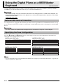
Using the Digital Piano as a MIDI Master
Keyboard
MASTER CONTROL
A unique MIDI channel can be assigned to each of the Digital Piano’s four zones (UPPER 1, UPPER 2, LOWER 1,
LOWER 2) to provide simultaneous control of up to four external MIDI devices.
IMPORTANT!
• This section provides only basic information about how to use the Digital Piano as a MIDI master keyboard. For
details about the MIDI specifications of this Digital Piano, see the “MIDI Implementation” document at the website
located at the URL below.
http://world.casio.com/
External MIDI Device Connection
Your Digital Piano is equipped with standard 5-pin DIN connector type MIDI OUT and MIDI IN terminals. It is up
to you to purchase optionally available or commercially available MIDI cables when connecting to an external MIDI
device.
IMPORTANT!
• The MIDI terminals are disabled while the Digital Piano is connected to a computer via the USB port.
Specifying the Zone Configuration
Press the (LAYER) and (SPLIT) buttons so their lamps are lit in one of the combinations shown below to
achieve the zone configuration you want.
LAYER unlit, SPLIT unlit
LAYER lit, SPLIT unlit
UPPER 1
UPPER 2
UPPER 1
LAYER unlit, SPLIT lit
LOWER 1
LAYER lit, SPLIT lit
UPPER 1
LOWER 1
LOWER 2
UPPER 1
UPPER 2
NOTE
• You can change the ranges of the UPPER and LOWER zones using the procedure described under “To specify the
keyboard split point” (page E-14).
E-26
Using the Digital Piano as a MIDI Master Keyboard
After you use the (LAYER) and (SPLIT) buttons to select a zone configuration, you can turn internal sound
source control (INT) and external MIDI device control (EXT) on or off as required for each zone. Use the (INT/
EXT) button to specify what a zone controls.
To specify what a zone controls
1.
Press the button that corresponds to the zone whose settings you want to change: (UPPER 1)
button, (UPPER 2) button, (LOWER 1) button, (LOWER 2) button.
• The lamp of the button you press will light.
2.
Use the (INT/EXT) button to specify what you want the zone you selected in step 1 to control.
• Pressing the (INT/EXT) button cycles through the available settings, which are indicated by two lamps above the
button as illustrated below.
Lit
Lit
Lit
Unlit
Unlit
Unlit
Lit
Unlit
• The INT side lamp indicates the internal sound source, while the EXT side lamp indicates an external MIDI device. Keep
pressing the button until the lamp(s) of the device(s) you want the zone to control are lit.
3.
If you want to configure other zones, repeat steps 1 and 2 of this procedure as required.
NOTE
• If you want to use the Digital Piano exclusively as an external MIDI device controller, you can turn off the local
control setting (page E-39), which severs the actual connection between its keyboard and the internal sound
source.
Zone Setups
In addition to the MIDI channel, you can configure external MIDI device control settings and internal sound source
settings (tone selection, DSP settings) for each individual zone.
• For the procedure to use to select a tone for each zone, see “Layering and Splitting Tones” (page E-12).
• For information about configuring MIDI channel, mixer, DSP, and other detailed settings for each zone, see
“Editing Zone Parameters” (page E-28).
E-27
English
Specifying What Each Zone Controls
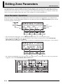
Editing Zone Parameters
MASTER CONTROL
Your Digital Piano is a four-zone MIDI master keyboard (“Master Control Configuration”, page E-4). A zone is a
unit that controls the internal sound source and/or external MIDI device. Just as you can select a different internal
sound source tone for each zone, you also can specify a mixer, DSP and other settings for an internal sound source,
and you can specify a MIDI channel and other control settings for an external MIDI device.
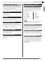
Zone Parameter Operations
The parameters whose settings can be configured for each zone are called “zone parameters.” To configure zone
parameter settings, enter the MASTER CONTROL mode and then hold down the (ZONE EDIT) button until the
zone menu appears on the display.
Page
Parameter Name
Zone Menu
Settings
• The zone menu has eight pages. Press the (ZONE EDIT) button to scroll through the pages.
• Each zone menu page includes up to four parameters, each of which corresponds one of the PARAMETER
SELECTOR buttons ( (A) through (D)).
• The format of the DPS settings on page 3 of the zone menu is a bit different from the other pages, as shown below.
• The “ZONE PARAMETER” list in the upper left of the Digital Piano’s control panel shows the zone parameters
assigned to each of the PARAMETER SELECTOR buttons.
E-28
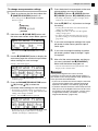
To change zone parameter settings
1.
5.
Check to make sure that the lamp above the
(MASTER CONTROL) button is lit.
• If it is unlit, press the (MASTER CONTROL)
• The lamp of the button you press will light, which
indicates its zone is selected.
button to light it.
Lit
2.
3.
6.
Use the (ZONE EDIT) button to display the
zone menu page that contains the parameter
whose setting you want to change.
Example: Zone menu page 2
Use the (EDIT w, q) buttons to change
the setting.
• Pressing w and q at the same time returns the
setting to its initial default.
• Holding down w or q will scroll through the
settings at high speed.
• For details about the meaning and range of each
parameter setting, see “Zone Parameter Settings”
(page E-30).
Hold down the (ZONE EDIT) button until
the zone menu screen shown below appears.
• This will cause the (ZONE EDIT) button lamp to
light.
Press the button that corresponds to the zone
whose settings you want to change:
(UPPER 1) button, (UPPER 2) button,
(LOWER 1) button, (LOWER 2) button.
7.
If you want to change the setting of the same
parameter in other zones, perform steps 5
and 6 again.
8.
If you want to change the setting of another
parameter, perform steps 3 through 7 again
as required.
9.
After all of the zone parameters are the way
you want, hold down the (ZONE EDIT)
button until the button lamp goes out.
• This will return the menu along the bottom of the
display to the common menu.
IMPORTANT!
• Each press of the (ZONE EDIT) button advances
to the next page.
4.
Press the PARAMETER SELECTOR button
( (A) through (D)) to select the
parameter whose setting you want to change.
• The brackets around the setting of parameter you
select will change from [ ] to %. This indicates that
editing of the setting is enabled.
Example: After the (C) button is pressed
Turning off the Digital Piano causes all zone
parameters to return to their initial default settings. If
you need to save a zone parameter setup, perform one
of the operations described below.
• If you want to restore the current setup the next time
you turn on the Digital Piano, perform the backup
operation. For details, see “Backup” (page E-40).
• If you don’t need to restore the current setup the next
time you turn on the Digital Piano but want to have it
on hand for recall when you need it, save the setup
to registration memory. For details, see “Using
Registration Memory” (page E-34).
• Holding down one of the PARAMETER SELECTOR
buttons will display its full name. For example,
“MidCh” will change to “MIDI Out Ch”.
E-29
English
Editing Zone Parameters
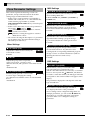
Editing Zone Parameters
MIDI Settings
Zone Parameter Settings
This section explains the meaning of each zone
parameter, and provides information about their
setting ranges and initial default values.
• In this section, each parameter is preceded by a
number and a letter, like “1-A”. This indicates the
common menu page number (1) and the
PARAMETER SELECTOR button you need to press
to select it (A).
• In this section, the name of each zone parameter is
followed by INT and/or EXT .
INT indicates a setting that applies to internal
sound source control.
EXT indicates a setting that applies to external
MIDI device control.
■ 2-A MIDI Out Channel (MidCh)
Specifies the MIDI channel used by each zone
when sending MIDI data.
1 to 16 (*UPPER 1: 1, UPPER 2: 2, LOWER 1: 3,
LOWER 2: 4)
■ 2-B Bank MSB (BnkMS)
Specifies the value of the bank MSB that is
appended when sending a program change
to an external destination with operation 2-D.
0* to 127
• The values following the description of a parameter
are its setting range. The initial default setting is
indicated by an asterisk (*).
Mixer Settings
■ 2-D Program Change (Prog)
Adjusts the volume level. 0 is mute, 127
is maximum volume.
0 to 127*
INT / EXT
■ 1-B Pan
Adjusts the pan position. 0 specifies a
INT / EXT
center pan position, a negative value
shifts it to the left, and a positive value shifts it to the
right.
–64 to 0* to +63
■ 1-C Octave Shift (Oct)
Shifts the pitch upwards or downwards
INT / EXT
in octave steps. Changing this setting
also shifts the note number sent to an external MIDI
device.
–2 to 0* to +2
EXT
■ 2-C Bank LSB (BnkLS)
Specifies the value of the bank LSB that is
appended when sending a program change
to an external destination with operation 2-D.
0* to 127
■ 1-A Volume (Vol)
EXT
EXT
Specifies the program change number sent to
EXT
an external destination. Any time this value
is changed, the corresponding numbered program
change is sent to an external destination (without
affecting the internal sound source).
0* to 127
DSP Settings
■ 3-A DSP Type (DSP)
Selects tremolo, rotary, or some other DSP
INT
type. The DSP type is indicated by “ton”
(which is the initial default for each tone) or a number
from 1 to 64. Any time the (EDIT w, q) buttons
are used to switch the number, the DSP type name that
corresponds to the current number will appear on the
display.
The parameters displayed in 3-B depend on the DSP
type selected here.
■ 3-B DSP Parameter (Parameter)
In accordance with the DSP type selected in
INT
3-A, displays the name of the parameters
whose settings can be configured. When there are
multiple parameters, you can use the (EDIT w,
q) buttons to scroll through them. Perform the
operation under 3-C to change the setting of a
parameter.
E-30
■ 3-C Parameter Value (Value)
■ 5-B Release Time (Relas)
This item is used to change the setting
of the parameter displayed in 3-B.
Release time is the time it takes for the
INT / EXT
sound to fade when a note ends.
Adjustment is relative from the initial default setting
(0) of each tone. A larger negative absolute value
shortens the release time, while a larger positive value
lengthens the release time.
–64 to 0* to +63
INT / EXT
IMPORTANT!
• For details on information about parameter names
and the settings and initial defaults for each
parameter under each DSP type number and type
name, see “DSP Effect List” (page E-60) and “DSP
Algorithm List” (page E-61).
Editing Tones
■ 4-A Coarse Tune (CrsTu)
Changes the pitch in semitone steps.
–12 to 0* to +12 semitones
INT / EXT
■ 4-B Fine Tune (FinTu)
Use this item to adjust the pitch in cent
steps (1 cent = 1/100 semitone).
–99 to 0* to +99 cents
INT / EXT
■ 5-C Filter Cutoff (Flter)
This item is for adjusting how the cutINT / EXT
off filter application is applied to a tone.
The cut-off filter is a tone adjustment filter that
eliminates (cuts off) all components over a given
frequency from within a tone’s overtone components.
Adjustment is relative from the initial default setting
(0) of each tone.
A larger negative absolute value produces a softer
sound, while a larger positive absolute value produces
a harder, brighter sound.
–64 to 0* to +63
■ 4-C Portamento ON/OFF (Porta)
■ 5-D Touch Sense (Sense)
Specifies whether or not portamento
INT / EXT
should be applied to each zone when
the assignable button to which portamento is assigned
is pressed.
OFF*, ON
This item is for adjusting how much the
INT
sound volume and timbre changes, and how
it changes in accordance with keyboard pressure.
Setting a larger absolute value causes relatively large
change in sound volume and timbre in response to
changes in key pressure. If this setting is 0, sound
volume and timbre remain constant regardless of key
pressure.
If the setting is positive, a larger value results in harder
notes when stronger pressure is applied, and softer
notes when lighter pressure is applied. If the setting is
negative, a larger value results in softer notes when
stronger pressure is applied, and harder notes when
lighter pressure is applied. The change in sound
volume and timbre depends on the tone.
–64 to 0 to +63*
■ 4-D Portamento Time (PTime)
Specifies the pitch change time when
INT / EXT
portamento is turned on in 4-C. A
smaller number specifies a shorter time, while a larger
number specifies a longer time. Portamento is not
applied when this setting is 0.
0* to 127
■ 5-A Attack Time (Atack)
Attack time is the time it takes for the
INT / EXT
sound to reach full volume when a note
is played. This item makes relative adjustments to the
default attack time (0) of each tone. A larger positive
value lengthens the attack time, which produces a
slower attack. A larger negative absolute value
shortens the attack time, which produces a faster
attack.
–64 to 0* to +63
■ 6-A Vibrato Rate (VbRat)
This item is for adjusting the speed of
INT / EXT
vibrato applied to notes. A larger
negative absolute value decreases the speed, while a
larger positive value increases the speed.
–64 to 0* to +63
E-31
English
Editing Zone Parameters
Editing Zone Parameters
Effect Settings
■ 6-B Vibrato Depth (VbDpt)
This item is for adjusting the depth
INT / EXT
(strength) of vibrato applied to notes. A
larger negative absolute value makes vibrato
shallower, while a larger positive value makes it
deeper.
–64 to 0* to +63
■ 6-C Vibrato Delay (VbDly)
This item is for adjusting the time until
INT / EXT
vibrato starts to be applied to a note. A
larger negative absolute value makes the time it takes
before vibrato is applied after a note is played shorter,
while a larger positive value makes it longer.
–64 to 0* to +63
■ 6-D Vibrato Waveform (WvFrm)
This item is for selecting the waveform when
applying vibrato to notes. You can select
from among the following waveforms.
Original (Org*)
Sine (Sin)
––
INT
Saw Down (SDw)
Pulse 1:3 (P13)
Triangle (Tri)
Pulse 2:2 (P22)
Saw Up (SUp)
Pulse 3:1 (P31)
* “Org” is the initial default setting for all tones. The
actual default waveform type depends on the tone.
For details on the meanings of the settings in this
section, see the flowchart under “Master Control
Configuration” (page E-4).
■ 7-A Reverb Send (RvbSd)
Specifies how much of the signal from
INT / EXT
the sound source is sent to reverb.
0 to 127 (*default setting depends on the tone)
■ 7-B Chorus Send (ChoSd)
Specifies how much of the signal from
INT / EXT
the sound source is sent to chorus.
0 to 127 (*default setting depends on the tone)
■ 7-C Acoustic Resonance Send (AReso)
Specifies how much of the signal from the
sound source is sent to acoustic resonance.
0 to 127 (*default setting depends on the tone)
INT
■ 7-D DSP ON/OFF (DSP)
Switches DSP for each zone on or off.
Selecting OFF disables DSP for that particular
zone.
OFF, ON*
INT
The DSP of this Digital Piano can be used
simultaneously for up to two parts. Each part (“Sound
Source Configuration”, page E-5) has a DSP priority,
which determines which of the two parts that have
DSP turned on should have the DSP effect applied. The
following shows the priorities assigned to each part.
Priority
Part Number
Part Name
1
Part 1
Upper1
2
Part 3
Lower1
3
Part 2
Upper2
4
Part 4
Lower2
5
Part 17 to 48
Song01 to Song16,
Ext01 to Ext16
To apply a DSP to one or two lower priority parts
(Lower2, for example), turn off DSP ON/OFF for the
higher priority parts (Upper1, Lower1, Upper2).
E-32
Editing Zone Parameters
Control Settings
English
If you are using multiple zones for keyboard play and
you want to disable pedal and other controller
operations for a particular zone, turn off the settings
described in this section for that zone.
■ 8-A Pedal
Enables and disables pedal operations.
OFF, ON*
INT / EXT
■ 8-B Bender (Bend)
Enables and disables the (PITCH
BEND) wheel operations.
OFF, ON*
INT / EXT
■ 8-C Assignable 1 (Asgn1)
Enables and disables the
(ASSIGNABLE 1) button operations.
OFF, ON*
INT / EXT
■ 8-D Assignable 2 (Asgn2)
Enables and disables the
(ASSIGNABLE 2) button operations.
OFF, ON*
INT / EXT
E-33
Using Registration Memory
MASTER CONTROL
Normally, before playing something you need to set up
the Digital Piano by configuring a number of different
settings, including layer and split on/off, a tone
selection for each zone, equalizer settings, and DSP
settings. You can save up to 64 Digital Piano setups
(which include control panel and internal settings) to
registration memory for later recall when you need
them. Each setup is saved as “registration data.”
Registration Data
The following are the settings that are stored as
registration data when you save a Digital Piano setup.
• Layer ON/OFF
• Split ON/OFF
• Split point
• Reverb ON/OFF
• Reverb type
• Chorus ON/OFF
• Chorus type
• Each zone tone number
• Each zone INT/EXT ON/OFF
• All common parameters (page E-18)
• All zone parameters (page E-28)
• Following function menu items (page E-38)
• Touch Response
• Pedal Assign
• Temperament type
• Temperament key note
• Stretch Tuning
• Acoustic Resonance ON/OFF
• Half Pedal Effect
NOTE
• The Digital Piano’s current mode (MASTER
CONTROL, CARD PLAYER, ZONE EDIT) is not
included in registration data. This means that the
Digital Piano’s mode does not change when you
recall registration data.
• The following function menu settings are not
included in registration data. You can, however,
perform the backup operation (page E-40) to retain
these settings when the Digital Piano is turned off.
• Tuning
• EQ Hold
• Display Contrast
• Song MIDI Out
• Song Volume
• Song Pre-count
• Song Repeat
• The backup operation (page E-40) saves all of the
above function menu settings, as well as all of the
settings that are included in registration data.
E-34
CARD PLAYER
Registration Memory
Operations
During registration data save and recall operations, the
location of the data in registration memory is specified
using a bank number and an area number. Registration
memory has eight banks, each of which is divided into
eight areas.
To save a setup as registration data
1.
Configure the Digital Piano with the settings
you want to save.
2.
Press the (REGISTRATION) button so the
lamp below it is lit. This is the
REGISTRATION mode.
Lit
Bank number
3.
Use the (w, q) buttons to scroll through
the banks (1 to 8) until the bank where you
want to save the registration data is
displayed.
Using Registration Memory
ck
While holding down the (STORE) button,
press one of the number buttons ( (1)
through (8)) to specify the number of the
area (1 to 8) where you want to save the
registration data.
cl
cm
cn
co
cp
cq
cr
dm
• Pressing a number button immediately executes the
registration data save operation.
• The following shows how the display would appear
if you select Bank 1, Area 3.
To rename a registration memory bank
1.
While holding down the (FUNCTION)
button, press the (REGISTRATION)
button.
2.
Use the (w, q) buttons to scroll through
the banks (1 to 8) until the one you want to
rename is displayed.
• This displays a screen for editing the name.
3.
Edit the name.
• The initial default name of all the banks is
“REGIBANKNAME”.
• Use the (u) and (i) buttons to move the
cursor left and right, and the (w, q) buttons to
scroll through characters at the current cursor
position. The following shows the characters that can
be used in a name.
Area number
Bank number
0
A
K
U
(
To recall a setup saved as registration
data
1.
Press the (REGISTRATION) button so the
lamp below it is lit. This is the
REGISTRATION mode.
2.
Use the (w, q) buttons to scroll through
the banks (1 to 8) until the one where the
registration data you want to recall is
displayed.
3.
Press one of the number buttons ( (1)
through (8)) to specify the number of the
area (1 to 8) where the registration data you
want to recall is located.
• Pressing a number button immediately recalls and
applies the setup in accordance with the registration
data being recalled.
• The following shows how the display would appear
if you select Bank 3, Area 7.
1 2 3
B C D
L M N
V W X
) - ^
4
E
O
Y
{
5 6
F G
P Q
Z S
} @
7
H
R
&
~
8
I
S
_
`
9
J
T
'
• You can specify up to 12 characters for a bank name.
4.
After the name is the way you want, press the
(ENTER) button.
5.
In response to the confirmation message
(“Sure?”) that appears, press the (YES)
button to apply the change or the (NO)
button to return to the screen in step 3 of this
procedure without changing anything.
NOTE
• To display a bank name, hold down the
(REGISTRATION) button on the registration mode
screen.
E-35
English
4.
Using Registration Memory
Saving Registration Memory
Bank Data to a File
3.
Registration data can be stored to a file in the Digital
Piano’s internal memory area or on an SD card. You
can store the registration data in a single registration
memory bank (eight areas) or the data in all of the
registration memory banks (64 areas) to a file.
Depending on the type of operation you want
to perform, use the (u) and (i)
buttons to display one of the screens shown
below.
To save the data in a single bank
NOTE
• When you save registration memory bank data to a
file, a file name is assigned automatically in
accordance with the following rules.
• If you save the data in a single bank, the file name
will be in the format: <first 6 characters of bank
name><2-digit number specified by you>.CB6.
• If you save the data in all the banks, the file name
will be in the format: <REGIST><2-digit number
specified by you>.CR6.
• Before saving registration memory bank data to an
SD card, be sure to first read the important
information contained in the following sections of
this user’s guide.
• “Card and Card Slot Precautions” (page E-46)
• “To load and remove a memory card” (page E-46)
• “To format a memory card” (page E-46)
To save the data in all banks
4.
Use the (w, q) buttons to specify the
two-digit number you want to append to the
name of the file.
5.
Press the (ENTER) button.
• This saves the file.
• The message “Replace?” will appear if a file with the
same name already exists. If you want to replace the
existing file with the one you are saving, press
(YES). Press (NO) to return to the screen in step 4
of this procedure without saving.
To save registration memory bank data to
a file
1.
Depending on where you want to save the
data file, perform one of the steps shown
below.
If you are saving the file
here:
Perform this operation:
Internal area
Remove the SD card from the
Digital Piano’s card slot.
SD card
Insert the SD card into the
Digital Piano’s card slot.
2.
While holding down the (FUNCTION)
button, press the (LOAD/SAVE) button.
• This enters the LOAD/SAVE mode.
E-36
6.
To exit the LOAD/SAVE mode, press the
(EXIT) button.
NOTE
• A registration memory bank data file saved to an SD
card will be placed in the MUSICDAT folder. The
MUSICDAT folder is created automatically when
you format the memory card on the Digital Piano
(page E-46). Note that load, delete, and rename
operations cannot be performed on files that are not
inside the MUSICDAT folder, or on files in folders
that are inside the MUSICDAT folder. Keep this
restriction in mind whenever handling SD card files
with your computer.
To recall registration memory bank data
from a file
1.
Depending on where the file is located,
perform one of the steps shown below.
If the file is located
here:
Perform this operation:
Internal area
Remove the SD card from the
Digital Piano’s card slot.
SD card
Insert the SD card into the Digital
Piano’s card slot.
2.
Press the (REGISTRATION) button so the
lamp below it is lit. This is the
REGISTRATION mode.
3.
If you are recalling a file that contains data for
a single bank, use the (w, q) buttons to
scroll through the bank numbers (1 through 8)
until the one to which you want to recall the
data is displayed.
7.
To replace the registration data currently in
the bank(s) you selected with the registration
data in the file, press the (YES) button. To
return to the screen in step 6 of this
procedure without recalling anything, press
the (NO) button.
• Pressing the (YES) button recalls the data from the
file into the bank(s) and exits the LOAD/SAVE
mode.
• If you are recalling a file that contains data for all
banks, you can skip this step.
4.
While holding down the (FUNCTION)
button, press the (LOAD/SAVE) button.
• This enters the LOAD/SAVE mode.
5.
Depending on the type of operation you want
to perform, use the (u) and (i)
buttons to display one of the screens shown
below.
To recall a file that contains data for a single bank
To recall a file that contains data for all banks
6.
Use the (w, q) buttons to display the
file that contains the data you want to recall,
and then press the (ENTER) button.
• This will cause the message “Replace?” to appear.
• To cancel the recall operation and exit the LOAD/
SAVE mode, press the (EXIT) button.
E-37
English
Using Registration Memory
Using the Function Menu
MASTER CONTROL
The function menu contains global settings (overall
tuning and touch adjustment, local control ON/OFF,
etc.) that need to be changed by you relatively
infrequently. It also includes some SD card operations
(format, etc.)
Function Menu Operations
This section explains operations involving function
menu settings. For details about specific function menu
items, see “Function Menu Settings” (page E-39).
To change the setting of a function menu
item
1.
Press the (FUNCTION) button.
• The button’s lamp will light, and the display will
change as shown below.
Item name
2.
“%” indicates the setting.“>ENT”
indicates a setting group.
You can use a number button ( (1) through
(8)) to select another item to change its
setting.
• Each number button corresponds to the numbers of
the items under “Function Menu Settings” (page
E-39).
• You also can scroll sequentially through settings with
the (u) and (i) buttons.
• “>ENT” to the right of an item indicates a setting
group. In this case, press the (ENTER) button to
enter the setting group. Next, use the (u) and
(i) buttons to scroll through the items in the group.
ENTER
EXIT
• To exit a setting group, press the (EXIT) button.
E-38
3.
CARD PLAYER
Use the (w, q) buttons to change the
currently displayed setting.
• Holding down the (FUNCTION) button as you
press w or q will change the setting by a factor of
10.
4.
To exit the function menu, press the
(EXIT) button or the (FUNCTION) button.
IMPORTANT!
• Turning off the Digital Piano causes all function
menu settings to return to their initial defaults. If you
need to save a function menu setup, perform the
backup operation. For details, see “Backup” (page
E-40).
• Some function menu settings also can be saved to
registration memory. For details, see “Using
Registration Memory” (page E-34).
Using the Function Menu
6 Temperament/Effect
This section explains the meaning of each function
menu parameter, and provides information about their
setting ranges and initial default values.
• For each item, the initial default setting is indicated
by an asterisk (*).
Temperament
1 Tuning
00*
01
02
03
04
05
06
07
08
(Tune)
Use this item to adjust the pitch in cent steps (1 cent =
1/100 semitone).
–99 to 0* to +99 cents
2 EQ Hold
Select OFF* to overwrite existing equalizer settings
when recalling registration data (page E-34). Select ON
to retain existing equalizer settings.
3 Touch Response
(Touch)
Select one of the settings below to specify the
relationship between key pressure and note volume.
OFF:
1
:
2* :
3
:
Constant note volume regardless of keyboard pressure
Strong sound even with light pressure
Normal
Normal sound even with strong pressure
4 Pedal Assign
(PedAssign)
Specifies whether the pedal unit connected to the
SOFT/SOSTENUTO PEDAL jack is a soft pedal (SFT*)
or a sostenuto pedal (SOS).
5 Local Control
(LocalCtl.)
Select OFF to disconnect the Digital Piano’s keyboard
from the internal sound source.
OFF, ON*
(Tmpr/Effect)
(Temper.)
Use this setting to select one of the temperaments
(tunings) shown below for the internal sound
source. Pressing a keyboard key while this item is
displayed will set that key’s note name (C* to B) as
the temperament key note.
:
:
:
:
:
:
:
:
:
Equal
Pure Major
Pure Minor
Pythagorean
Kirnberger 3
Werckmeister
Mean-Tone
Rast
Bayati
09
10
11
12
13
14
15
16
:
:
:
:
:
:
:
:
Hijaz
Saba
Dashti
Chahargah
Segah
Gurjari Todi
Chandrakauns
Charukeshi
NOTE
• Equal temperament is always used for MIDI file
playback in the CARD PLAYER mode.
Stretch Tuning
(Stretch)
Stretch tuning is a standard piano tuning method
that tunes high notes slightly higher and low notes
slightly lower. Select ON* for this item to enable
stretch tuning or OFF for plain tuning.
Acoustic Resonance
(AcoReson.)
Acoustic resonance occurs when the damper pedal
is depressed on a grand piano. Select ON* for this
item to enable acoustic resonance or OFF to disable
it.
Half Pedal Effect
(HalfPedal)
Use this item to adjust how much a half-pedal
operation (pressing the pedal part way) when using
the damper pedal of the optional pedal unit (SP-32).
A setting of 00 disables the half pedal effect. Setting
42 applies a full-press effect, even when the pedal is
pressed part way.
00 to 24* to 42
E-39
English
Function Menu Settings
Using the Function Menu
7 Playback/Card
(Play/CARD)
Song MIDI Out
(MIDI Out)
Select ON* for this item to send MIDI data to an
external destination when a Format0 or Format1
SMF file is played back on the Digital Piano. Select
OFF to disable send. MIDI data is never sent during
playback of a CM2 format file, regardless of what is
selected for this setting.
Song Volume
(SongVol.)
Use this item to adjust the volume level for
playback of MIDI files on the Digital Piano. This
item can be used to balance the volume level of
MIDI file playback with keyboard play volume. A
setting of 00 mutes MIDI file playback.
00 to 42*
Song Pre-count
(PreCount)
Select ON for this item to sound a pre-count at the
beginning of a song when starting playback of a
MIDI file on the Digital Piano. Select OFF* to
disable the pre-count.
Song Repeat
(SngRepeat)
Select ON for this item to repeat a single song when
playing back a MIDI file on the Digital Piano. Select
OFF* to disable song repeat.
Card Folder Setting
(CardFolder)
See “Creating a New Card Music Folder” (page
E-44).
Card Format
(CardFORMAT)
See “To format a memory card” (page E-46).
File Delete
(FileDELETE)
See “To delete a file” (page E-47).
File Rename
(FileRENAME)
See “To rename a file on a memory card” (page
E-47).
E-40
8 Other
(General)
Panel Lock
(PanelLock)
Turning on panel lock locks all of the Digital
Piano’s buttons (except for the power button and
unlock button operations*). Turn on panel lock
when you want to protect against unintentional
button operations. Turning off the Digital Piano
automatically unlocks panel lock.
* To unlock the panel, perform the same operation
you perform to turn on panel lock.
Display Contrast
(Contrast)
Use this item to adjust display contrast.
00 to 08* to 16
Backup
(BackUp)
Changing this item from OFF* to ON, creates a
backup data file that contains information about all
of the Digital Piano’s current settings. If this item is
left ON, the Digital Piano’s setup is configured in
accordance with the contents of the currently saved
backup data file. For details about the backup data
file contents, see the note at the end of “Registration
Data” (page E-34).
NOTE
• Changing the backup setting from ON to OFF
deletes the current backup data file. Turning the
Digital Piano off and then back on again while
the backup setting is OFF will cause all settings
to return to their initial power on defaults.
Registration memory data and internal memory
area data is not affected.
• To update the contents of the backup data file
with your current Digital Piano setup, change
the backup setting from ON to OFF and then
back to ON again.
Playing Back a MIDI File
You can use the Digital Piano to directly playback a
MIDI file stored on an SD card. You also can copy
MIDI files to the Digital Piano’s built-in memory
(internal memory area) and play it back from there.
IMPORTANT!
• Your Digital Piano supports playback of Format0 and
Format1 SMF files and CM2 (CASIO proprietary)
format file. Playback of up to 17 tracks of a Format1
SMF file is supported.
• Playback of audio files (WAV, MP3, etc.) is not
supported.
5.
• A: MUSICDAT, B: MUSIC__B, C: MUSIC__C,
D: MUSIC__D.
6.
Use the (w, q) buttons to select the
MIDI file you want.
7.
To start playback, press the (PLAY/
STOP) button.
• Press the (FF) button to perform a fast forward
operation or the (REW) button for rewind.
Pressing and releasing either button moves one
measure, while holding down a button scrolls at high
speed.
• Pressing the (PAUSE) button pauses playback.
Press again to resume song playback.
• For information about other operations that are
supported during playback, see “Supported
Operations During MIDI File Playback” (page E-42).
• Playback will stop when the end of the file is reached
(under initial default settings). To stop playback part
way through, press the (PLAY/STOP) button.
MIDI File Playback Operations
To play back a MIDI file from an SD card
1.
Format the SD card on the Digital Piano
(page E-46).
• This will cause folders with the names MUSICDAT,
MUSIC__B, MUSIC__C, and MUSIC__D to be
automatically created in the SD card’s root directory.
2.
3.
4.
Use your computer to copy the MIDI files you
want to play on the Digital Piano into the
folders that were created on the SD card in
step 1 of this procedure.
Insert the SD card into the Digital Piano’s
card slot.
Press the (CARD PLAYER) button so the
lamp below it is lit. This is the CARD PLAYER
mode.
• The (A) button will light, and the name of the first
MIDI file in the MUSICDAT folder will appear on the
Digital Piano’s display.
You can use the letter buttons ( (A) through
(D)) to specify an SD card folder.
8.
To exit the CARD PLAYER mode, press the
(CARD PLAYER) button.
• The lamp above the button will light, and the Digital
Piano will return to the MASTER CONTROL mode.
To play back a MIDI file from the Digital
Piano’s internal memory area
1.
Copy the MIDI file you want to play to the
Digital Piano’s internal memory area.
• For information about how to copy the file, see
“Transferring Data between the Digital Piano and a
Computer” (page E-50).
2.
If there is an SD card in the Digital Piano’s
card slot, remove it.
E-41
English
CARD PLAYER
Playing Back a MIDI File
3.
Press the (CARD PLAYER) button so the
lamp below it is lit. This is the CARD PLAYER
mode.
• This displays the name of the first MIDI file in the
internal memory area.
• The remaining steps of this procedure are the same as
those starting with step 6 under “To play back a MIDI
file from an SD card” (page E-41).
■ To adjust the tempo by tapping a beat
1.
While holding down the (FUNCTION)
button, tap the q (TEMPO) button four
times in time with the beat you want to
specify.
• The tempo setting will change in accordance with the
timing of your tapping.
• After you use this method to specify the approximate
tempo, you can then use the procedure under “To
adjust the tempo using the (TEMPO w, q)
buttons” to adjust the setting to a more exact value.
• The setting will be canceled if you release the
(FUNCTION) button before tapping the q
(TEMPO) button four times.
Tap four times
Supported Operations During
MIDI File Playback
To change the playback tempo
There are two different methods you can use to change
the tempo setting: by pressing q (faster) and w
(slower) buttons or by tapping a beat with a button.
■ To adjust the tempo using the (TEMPO
w, q) buttons
Each press of a button increases or decreases the beats
per minute value by one.
• Holding down either button changes the value at
high speed.
• Pressing both of the (TEMPO w, q) buttons at
the same time will return the song to its default
tempo.
• You can specify a tempo value in the range of 20 to
255.
Tempo value
E-42
To adjust playback volume in accordance
with keyboard play volume
See “Song Volume” (page E-40). For information about
how to change the setting, see “To change the setting of
a function menu item” (page E-38).
To sound a pre-count at the start of
playback
See “Song Pre-count” (page E-40). For information
about how to change the setting, see “To change the
setting of a function menu item” (page E-38).
Playing Back a MIDI File
NOTE
• To perform the procedure below, use a MIDI file that
has the left-hand part recorded in Channel 3 and the
right-hand part recorded in Channel 4.
1.
Enter the CARD PLAYER mode and select
the MIDI file you want to play.
2.
Press the (PART) button.
To play on the keyboard along with
playback
1.
• See “Selecting a Tone” (page E-11) and “Layering and
Splitting Tones” (page E-12).
2.
• This will display the part on/off screen (L-[ON]
R-[ON]) to appear on the display.
3.
Use the (w, q) buttons to toggle the
parts on and off.
• w toggles the left-hand part and q toggles the
right-hand part.
4.
Press the (PART) button to exit the part
on/off screen.
5.
To start playback, press the (PLAY/STOP)
button.
• This starts playback of the part you turned on in
step 2. You can play the part you turned off on the
keyboard along with the playback.
In the MASTER CONTROL mode, select the
tones you want to use for each zone you will
play on the keyboard.
Enter the CARD PLAYER mode and start
MIDI file playback.
• See “MIDI File Playback Operations” (page E-41).
3.
Play on the keyboard along with playback.
NOTE
• The parts used for MIDI file playback (Song01
through Song16) are independent of the parts used
for Digital Piano keyboard play (Upper1, Upper2,
Lower1, Lower2). For more information, see “Sound
Source Configuration” (page E-5). This means that
playing on the keyboard does not interfere with
proper MIDI file playback.
• You can select the tones for each zone you will play
on the keyboard after entering the CARD PLAYER
mode. For more information, see “To select a tone
for each zone in the CARD PLAYER mode” (page
E-44).
To repeat play a specific section of a
song
1.
Press the (PLAY/STOP) button to start
song playback.
2.
When playback reaches the first beat of the
section you want to select for repeat, press
the (REPEAT) button.
• This will cause the (REPEAT) button lamp to
flash.
3.
When playback reaches the last beat of the
section, press the (REPEAT) button again.
• The (REPEAT) button lamp will remain lit, which
indicates that repeat playback is being performed.
After a one-measure (four beats in the cast of a 4/4
time song) rest, the Digital Piano will start playing
the section you selected. Playback of the selected
section continues, with a one-measure rest before
each playback.
• You can use the (PLAY/STOP) button to stop and
re-start playback of the section.
4.
To exit repeat playback, press the
(REPEAT) button again so its lamp goes out.
• Using the (w, q) buttons to switch to another
song also will exit repeat playback.
E-43
English
To practice with either hand (Part Off)
Playing Back a MIDI File
To select a tone for each zone in the
CARD PLAYER mode
1.
Press the (LAYER) and (SPLIT)
buttons so their lamps are lit in the
combinations shown below and select the
tones you want.
To change this
zone’s tone:
Configure the (LAYER) and
(SPLIT) button lamps like this:
UPPER 1 zone
(LAYER): unlit, (SPLIT): unlit
(LAYER): lit, (SPLIT): unlit
(LAYER): unlit, (SPLIT): lit
(LAYER): lit, (SPLIT): lit
UPPER 2 zone
LOWER 1 zone
LOWER 2 zone
2.
Press the (TONE) button so the lamp
above it is lit.
3.
Use the to (Tone Group) buttons to
select the group you want.
• The lamp of the button you press will light.
4.
5.
Use the (w, q) buttons to select the
tone you want.
Repeat steps 1 through 4 for all of the zones
you want to use for keyboard play.
Creating a New Card Music
Folder
When you insert an SD card, the Digital Piano searches
for MIDI files inside of specific folders on the card.
Under initial default settings, the folders that are
searched are named “MUSICDAT” (which is assigned
to Digital Piano button (A)), “MUSIC__B” (button
(B)), “MUSIC__C” (button (C)), and
“MUSIC__D” (button (D)). Pressing a button
accesses the contents of the corresponding folder.
You can use the procedure below to assign different
folders to buttons (B), (C), and (D).
• The procedure below creates a new folder and
assigns it to button (B), (C), or (D). Button
assignments are stored on the SD card, so if you
remove it, the last button assignments you used will
be restored the next time you insert the card.
• If you create more than one folder for a button, the
last one you create will be assigned to the button.
• Performing the procedure below does not delete or
affect the content of the folder currently assigned to
a button.
To create a new card music folder
1.
Insert the SD card into the Digital Piano’s
memory card slot.
2.
3.
4.
Press the (FUNCTION) button.
Press the (7) button.
Use the (u) and (i) buttons to
display “CardFolder” and then press the
(ENTER) button.
• This causes the CARD Folder screen to appear.
5.
E-44
Use the (w, q) buttons to scroll through
the button names (B, C, D) until the one for
which you want to create a new folder is
displayed within the brackets (%).
Playing Back a MIDI File
Enter a name for the folder you want to
create.
• Use the (u) and (i) buttons to move the
cursor left and right, and the (w, q) buttons to
English
6.
scroll through characters at the current cursor
position. The following shows the characters that can
be used in a name.
0
A
K
U
(
1 2 3
B C D
L M N
V W X
) - ^
4
E
O
Y
{
5 6
F G
P Q
Z S
} @
7
H
R
&
~
8
I
S
_
`
9
J
T
'
• If you know the name of an existing folder on the SD
card, you can input the name in the above step. This
will assign the existing folder to the applicable button
without creating a new folder.
7.
After the name is the way you want, press the
(ENTER) button.
8.
In response to the confirmation message
(“Sure?”) that appears, press the (YES)
button to create the new folder or the (NO)
button to return to the screen in step 6 of this
procedure without creating anything.
• The message “Please Wait” will remain on the
display while the operation is being performed. Do
not perform any Digital Piano operation while this
message is on the display. “Complete” appears on the
display after the operation is complete.
E-45
Using a Memory Card
MASTER CONTROL
You can save Digital Piano registration data to a
commercially available SD memory card, if you want.
Use a memory card with a capacity of 2GB or less.
Use of a card with a capacity that is greater than
2GB or other types of memory cards is not
supported.
In this manual, mentions of a “memory card” refer
to an SD memory card.
■ Types of Data
Data Type
Description
(File Name Extension)
Registration Digital Piano setups
(page E-34) (CB6, CR6)
Supported
Operations
Save to
Memory
Card
Load from
Memory
Card
O
O
CARD PLAYER
Memory Card Operations
To load and remove a memory card
IMPORTANT!
• A memory card must be positioned correctly when
being loaded into the Digital Piano. Trying to force
an improperly oriented memory card into the slot can
damage the memory card and the slot.
1.
With the top of the memory card facing
upwards (so you can see it), carefully insert it
into the Digital Piano’s memory card slot ()
until stops with a click.
Card and Card Slot Precautions
IMPORTANT!
• Be sure to observe the precautions provided in the
documentation that comes with the memory card.
• Memory cards have a write-protect switch. Use it
when you want to protect the data on the card from
accidental deletion.
• Avoid using a memory card under the following
conditions. Such conditions can corrupt data stored
on the memory card.
• Areas subjected to high temperature, high
humidity, or corrosive gas
• Areas subjected to strong electrostatic charge and
digital noise
• Never touch the contacts of a memory card when
loading it or removing it from the Digital Piano.
• Never eject the memory card while data is being
written to or loaded from it. Doing so can corrupt the
data on the memory card and damage the memory
card slot.
• Never insert anything besides a memory card into
the card slot. Doing so creates the risk of
malfunction.
• Electrostatic charge from your fingers or the memory
card to the card slot can cause malfunction of the
Digital Piano. If this happens, turn the Digital Piano
off and then back on again.
• A memory card can become quite warm after very
long use in the memory card slot. This is normal and
does not indicate malfunction.
E-46
Top
2.
To remove the memory card first press it into
the slot further.
This will cause the memory card to disengage and eject
partially. Pull the memory card the rest of the way out
of the slot.
To format a memory card
IMPORTANT!
• Format a memory card before using it for the first
time.
• Before formatting a memory card, make sure it does
not have any valuable data stored on it.
• The memory card format operation performed by this
Digital Piano is a “quick format”. If you want to
completely delete all of the data on the memory
card, format it on your computer or some other
device.
1.
Insert the memory card you want to format
into the Digital Piano’s memory card slot.
Make sure the write-protect switch of the memory card
is not in the write-protect position so writing is enabled.
2.
3.
Press the (FUNCTION) button.
Press the (7) button.
Using a Memory Card
Use the (u) and (i) buttons to
display “CardFORMAT” and then press the
(ENTER) button.
To rename a file on a memory card
1.
This will display a confirmation message (SURE?).
• If you want to cancel the format operation, press the
(NO) or (EXIT) button.
5.
Press the (YES) button.
• The message “Please Wait” will remain on the
display while the format operation is being
performed. Do not perform any Digital Piano
operation while this message is on the display.
“Complete” appears on the display after formatting
is complete.
• Formatting a memory card will cause folders with the
names MUSICDAT, MUSIC__B, MUSIC__C, and
MUSIC__D to be automatically created in the card’s
root directory.
• This step is not necessary if you are renaming a file
for the internal memory area.
2.
3.
4.
6.
Use the (u) and (i) buttons to move
the flashing cursor to the character you want
to change, and then use the (w, q)
buttons to change the character.
0
A
K
U
(
Press the (7) button.
5.
Use the (w, q) buttons to select the file
you want to delete.
6.
Press the (ENTER) button.
This will display a confirmation message (SURE?).
• If you want to cancel the delete operation, press the
(NO) or (EXIT) button.
7.
• The characters you can select are shown below.
Press the (FUNCTION) button.
This displays a screen for selecting a file for deletion.
Press the (YES) button.
• The message “Please Wait” will remain on the
display while the delete operation is being
performed. Do not perform any Digital Piano
operation while this message is on the display.
“Complete” appears on the display after deletion is
complete.
Use the (u) and (i) buttons to
display “FileRENAME” and then press the
(ENTER) button.
Use the (w, q) buttons to select the file
you want to rename.
Insert the SD card into the Digital Piano’s
card slot.
Use the (u) and (i) buttons to
display “FileDELETE” and then press the
(ENTER) button.
Press the (7) button.
5.
• This step is not necessary if you are deleting a file for
the internal memory area.
2.
3.
4.
Press the (FUNCTION) button.
This displays a screen for changing the file name.
To delete a file
1.
Insert the SD card into the Digital Piano’s
card slot.
7.
1 2 3
B C D
L M N
V W X
) - ^
4
E
O
Y
{
5 6
F G
P Q
Z S
} @
7
H
R
&
~
8
I
S
_
`
9
J
T
'
After the file name is the way you want, press
the (ENTER) button.
This will display a confirmation message (SURE?).
• If you want to cancel the renaming operation, press
the (NO) or (EXIT) button.
8.
Press the (YES) button.
• The message “Please Wait” will remain on the
display while the rename operation is being
performed. Do not perform any Digital Piano
operation while this message is on the display.
“Complete” appears on the display after renaming is
complete.
E-47
English
4.
Using a Memory Card
Error Messages
One of the error messages below appears on the display when a problem occurs.
• All mentions of “memory card” in the following table refer to an SD memory card.
Display
Message
Format
MediaFull
Media R/W
No Card
Cause
Required Action
1. The current memory card format is not compatible
with this Digital Piano.
1. Format the memory card on the Digital Piano (page E-46).
2. The memory card capacity is greater than 2GB.
2. Use a memory card with a capacity of 2GB or less.
3. There is something wrong with the memory card.
3. Use a different memory card.
1. There is not enough room available on the memory
card.
1. Delete some of the files on the memory card to make room for
new data (page E-47), or use a different card.
2. There is not enough room available in Digital Piano
memory.
2. Delete some or all user data from Digital Piano memory to make
room for new data.
1. Memory card data is corrupted.
1. Use a different memory card.
2. Digital Piano memory is corrupted.
2. Backup Digital Piano memory data by copying it to your
computer, and then turn the Digital Piano off and then back on
again.
• Note that you may not be able to backup Digital Piano data in
certain cases.
1. The memory card is not loaded correctly in the Digital 1. Correctly load the memory card into the memory card slot.
Piano’s memory card slot.
2. The memory card was removed while some operation 2. Do not remove the memory card while any operation is in
was in progress.
progress.
No File
1. There is no MUSICDAT folder (page E-41) on the
memory card.
1. Create a MUSICDAT folder on the memory card or format the
memory card on the Digital Piano (page E-46).
2. There is no loadable or playable data in the
MUSICDAT folder, or there is no playable data in a
song playback folder (MUSIC__B, etc.)
2. Move the file you want to load or play into the memory card’s
MUSICDAT folder. For song playback, you can place the song
data into any one of the following folders: MUSIC__B,
MUSIC__C, or MUSIC__D.
Not SMF01
You are attempting to play back SMF Format 2 song data. This Digital Piano supports playback of SMF Format0 or Format1
only.
Protect
The memory card is write-protected.
ReadOnly
A read-only file with the same name you are trying to use • Use a different name to save the new file.
is already stored on the memory card.
• Remove the read-only attribute from the existing file and
overwrite it with the new file.
• Use a different memory card.
SizeOver
The data on the memory card is too big to play.
This Digital Piano supports playback of song data files with a
maximum size of 320 KB.
WrongDat
1. The memory card data is corrupted.
—
2. The memory card contains data that is not supported
by this Digital Piano.
E-48
Use the memory card’s write protect switch to enable writing.
Connecting to a Computer
You can connect the Digital Piano to a computer and
exchange MIDI data between them. You can send play
data from the Digital Piano to music software running
on your computer, or you can send MIDI data from
your computer to the Digital Piano for playback.
2.
CARD PLAYER
After starting up your computer, use a
commercially available USB cable to connect
it to the Digital Piano.
B connector
USB cable
(A-B type)
Minimum Computer System
Requirements
The following shows the minimum computer system
requirements for sending and receiving MIDI data.
Check to make sure that your computer complies with
these requirements before connecting the Digital Piano
to it.
Operating System
Windows® XP (SP2 or later)*1
Windows Vista® *2
Windows® 7 *3
Mac OS® X (10.3.9, 10.4.11 or later, 10.5.6 or later, 10.6.2
or later)
*1 Windows XP Home Edition
Windows XP Professional (32-bit)
*2 Windows Vista (32-bit)
*3 Windows 7 (32-bit, 64-bit)
USB port
A connector
Digital Piano USB port
Computer USB port
3.
Turn on the Digital Piano.
• If this is the first time you are connecting the Digital
Piano to your computer, the driver software required
to send and receive data will be installed on your
computer automatically.
4.
5.
Start up your computer’s music software.
Configure the music software settings to
select one of the following as the MIDI device.
CASIO USB-MIDI : (For Windows Vista, Windows 7,
Mac OS X)
USB Audio Device: (For Windows XP)
• For information about how to select the MIDI device,
see the user documentation that comes with the
music software you are using.
IMPORTANT!
• Never connect to a computer that does not conform
to the above requirements. Doing so can cause
problems with your computer.
Connecting the Digital Piano
to Your Computer
IMPORTANT!
• Make sure you follow the steps of the procedure
below exactly. Connecting incorrectly can make data
send and receive impossible.
1.
Turn off the Digital Piano and then start up
your computer.
IMPORTANT!
• Be sure to turn on the Digital Piano first before
starting up your computer’s music software.
NOTE
• Once you are able to connect successfully, there is no
problem with leaving the USB cable connected when
you turn off your computer and/or Digital Piano.
• This Digital Piano conforms to General MIDI Level 1
(GM).
• For detailed specifications and connections that
apply to MIDI data send and receive by this Digital
Piano, see the latest support information provided
by the website at the following URL.
http://world.casio.com/
• Do not start up the music software on your computer
yet!
E-49
English
MASTER CONTROL
Connecting to a Computer
Transferring Data between the
Digital Piano and a Computer
3.
While holding down the (FUNCTION)
button, press the (USB DEVICE MODE)
button.
This will enter the storage mode, which enables data
transfer with the connected computer. The
(FUNCTION) button lamp will flash and the display
will appear as shown below.
You can use the procedure below to transfer
registration data from the Digital Piano to a computer
for storage. You also can transfer standard MIDI files
(SMF) from your computer to Digital Piano memory.
■ Data Types Supported for Data Transfer
Data Type
Description (File Name Extension)
MIDI files
(page E-41)
One of the following two types of music data
• CASIO format data (CM2)
• Standard MIDI files (MID),
SMF Format0 or Format1
• To exit the storage mode at any time, press the
(FUNCTION) button. This is the only button
operation that is supported while the Digital Piano is
in the storage mode.
• You will not be able to enter the storage mode while
any one of the following operations is in progress.
MIDI file playback, data transfer between the Digital
Piano and card
Registration Digital Piano setups (CB6, CR6)
(page E-34)
IMPORTANT!
• Turning off the Digital Piano while data is being
transferred can cause all data currently stored in
Digital Piano memory to be deleted. Take care so
power is not turned off accidentally during data
transfer operations. If data is deleted, it will take
longer than normal for the Digital Piano to power up
the next time you turn it on (page E-11).
1.
4.
If your computer is running Windows XP,
double-click “My Computer”.*
Under “Devices with Removable Storage”, you should
be able to see an icon representing Digital Piano
memory or the memory card loaded in the Digital
Piano (see below).
* Windows Vista, Windows 7: Double-click “Computer”.
Mac OS: Skip step 4 and double-click “PIANO” on
your Mac desktop.
Remove the memory card from the Digital
Piano’s memory card slot (page E-46).
• You will not be able to transfer data between the
Digital Piano and a computer if a card is in the
memory card slot.
2.
Perform steps 1 through 3 under “Connecting
the Digital Piano to Your Computer” to
connect the piano to your computer (page
E-49).
PIANO drive (Digital Piano memory)
5.
Double-click “PIANO”.
You now should see the folders below.
This folder is not a data folder. You should not try to use it for normal
Digital Piano operation.
E-50
Connecting to a Computer
File name extensions (.MID, .CM2, etc.) are
not displayed under initial default Windows
settings. Perform the procedure below to turn
on display of file name extensions.
(1) Perform one of the following operations to display
folder information.
• Windows XP:
On the [Tools] menu at the top of the folder
window, select [Folder Options].
• Windows Vista, Windows 7:
On the left side of the folder window, click
[Organize] and then select [Folder and Search
Options].
(2) On the Folder Information window, click the [View]
tab.
(3) Under “Advanced Settings”, clear the “Hide
extensions for known file types” check box and then
click [OK].
7.
8.
Perform one of the following operations to
transfer data.
7-1. To transfer data from Digital Piano
memory to a computer, perform the
required operation on your computer to
copy the data from Digital Piano memory
to another location on your computer.
7-2. To load a MIDI file (.MID or .CM2) from
your computer to Digital Piano memory,
copy the file you want to load to the root
directory of “PIANO” drive.
7-3. To load a registration data file (.CB6 or
.CR6) from your computer to Digital
Piano memory, copy the file you want to
load to the “REGISTMR” folder.
Using Your Digital Piano as a Memory
Card Reader
You can display the contents of the memory card
currently loaded in the Digital Piano’s card slot and
perform copy, delete, and other card operations from
your computer.
1.
Insert the memory card into the Digital
Piano’s memory card slot.
2.
Perform the procedure starting from step 2 on
page E-50.
In step 4 of the procedure, “SD_MMC” will appear in
place of “PIANO”. You can double-click “SD_MMC” to
display the contents of the card loaded in the Digital
Piano card slot, and change it as you like.
Copyrights
The rights of creators and copyright holders of music,
images, computer programs, databases, and other
data are protected by copyright laws. You are allowed
to reproduce such works for personal or noncommercial use only. For any other purpose, all
reproduction (including data format conversion),
modification, transfer of reproductions, distribution
over a network, or any other use without permission
of the copyright holder exposes you to claims for
damages and criminal prosecution for copyright
infringement and violation of the author’s personal
rights. Be sure to reproduce and otherwise use
copyrighted works only in accordance with applicable
copyright laws.
Press the (FUNCTION) button to exit the
storage mode.
• If you are using a Macintosh, drag the PIANO folder
to the Trash and then press the Digital Piano’s
(FUNCTION) button.
IMPORTANT!
• The message “ERROR, DATA EXCHANGE” will
appear on the display if a problem occurs during
data transfer. If this happens, check the message in
the “STATELOG” folder (page E-50) on the “PIANO”
drive. Next find the same message in the table on
page E-48 of this manual to determine the cause of
the problem and what action you need to take to
avoid it.
E-51
English
6.
Reference
Troubleshooting
Problem
Nothing comes out of the
connected headphones or
amplifier speakers when I play
something.
Cause
The (VOLUME) knob is set to
“MIN”.
The UPPER 1 zone setting is INT
OFF.
The pitch of the Digital Piano
is off.
The Digital Piano’s key setting is
something other than 0.
Digital Piano tuning is incorrect.
Tones and/or effects sound
strange. Turning power off
and then back on again does
not eliminate the problem.
Example: Note intensity does
not change even though I alter
key pressure.
I cannot hear any chorus/
reverb effect when I turn on
chorus/reverb.
I cannot play back a music file
from an SD card.
I cannot transfer data after
connecting the Digital Piano
to a computer.
I cannot store data to a
memory card or load data
from a memory card.
Playback stops part way
through while transferring
song data from my computer.
E-52
Action
Rotate the (VOLUME) knob more
towards “MAX”.
Change the UPPER 1 zone setting to INT
ON. If you are using Layer and/or Split,
change the setting of the zone you are
using to INT ON.
Change the key setting to 0, or turn Digital
Piano power off and then back on again.
Adjust Digital Piano tuning, or turn Digital
Piano power off and then back on again.
Change the setting(s) to 0 or turn Digital
Piano power off and then back on.
See Page
E-11
E-27
E-20
E-39
The Coarse Tuning and/or Fine
Tuning setting is something other
than 0.
A non-standard temperament setting Change the temperament setting to
is being used.
“00:Equal”, which is the standard modern
tuning.
Octave shift is enabled.
Change the octave shift setting to 0.
The “Backup” feature is turned on.
Turn off “Backup”. Next, turn power off
and then back on again.
E-31
The chorus send/reverb send setting Change the chorus send/reverb send
is 0.
setting to a greater value.
E-32
E-39
E-30
E-40
The file you are trying to play is not a This Digital Piano supports playback of
E-41
format supported by this Digital
Format0 or Format1 SMF files, or CM2
Piano.
(CASIO proprietary format) files only.
Playback of WAV and MP3 files, or other
format MIDI files is not supported.
—
• Check to make sure that the USB cable E-49
is connected to the Digital Piano and
computer, and that the correct device is
selected with your computer’s music
software.
• Turn off the Digital Piano and then exit
the music software on your computer.
Next, turn the Digital Piano back on and
then restart the music software on your
computer.
—
See “Error Messages” on page E-48.
—
Digital noise from the USB cable or
power cord caused data
communication between your
computer and Digital Piano to be
interrupted.
Stop song playback, disconnect the USB E-49
cable from the Digital Piano, and then
reconnect it. Next, try playing back the
song again.
If this does not solve the problem, quit the
MIDI software you are using, disconnect
the USB cable from the Digital Piano, and
then reconnect it. Next, restart the MIDI
software and then try playing back the
song again.
Problem
A tone’s quality and volume
sounds slightly different
depending where it is played
on the keyboard.
Cause
Action
See Page
This is an unavoidable result of the digital sampling process,* and does not indicate
malfunction.
* Multiple digital samples are taken for the low range, middle range, and high range of the
original musical instrument. Because of this, there may be a very slight difference in tonal
quality and volume between sample ranges.
When I press a button, the
Performing a button operation while playing back a MIDI file can cause such phenomena
note that is sounding cuts out when the Digital Piano switches internal tone effects. It does not indicate malfunction.
momentarily or there is a
slight change in how effects
are applied.
Even though I play on
The ranges of certain tones are limited, which means that octaves change normally up to a
different ranges of the
certain low note or high note. With such a tone, the notes of the lowest octave will be
keyboard, the notes do not
repeated to the left of the lowest possible note, and the highest octave will be repeated to the
change octaves.
right of the highest possible note. This is due do limitations in the range of the original musical
instrument for each tone, and does not indicate malfunction of the Digital Piano.
E-53
English
Reference
Reference
Product Specifications
Model
PX-3
Keyboard
88-key piano keyboard, with Touch Response (3 types)
Maximum Polyphony
128 notes
Tones
250 (with Layer and Split)
Effects
DSP, Reverb (4 types), Chorus (4 types), Brilliance (–3 to 0 to 3), Acoustic Resonance
Mixer
UPPER 1, UPPER 2, LOWER 1, LOWER 2; the volume level of each zone can be adjusted independently.
Assignable buttons
2
Demo Songs
4 original songs (played back sequentially and repeatedly)
Registration
8 areas × 8 banks
Pedals
Damper, Soft/Sostenuto (switchable)
Other Functions
•
•
•
•
•
•
MIDI
16 multi-timbre received, GM Level 1 standard
Transpose: ±1 octave (–12 to 0 to 12)
Tuning: A4 = 440.0 Hz ±99 cents
Octave Shift: ±2 octaves
Temperaments: 17 types
Stretch Tune
Panel Lock
Pitch Bend Wheel
Pitch Bend Range: 00 to 12 semitones
SD Memory Card
• SD memory card slot
• Supported SD Memory Cards: Up to 2GB
• Functions: SMF playback, file storage, file recall, card format
Inputs/Outputs
•
•
•
•
•
•
•
•
PHONES jacks: Stereo mini jacks × 2
Pedal Jacks: Standard jacks × 2
MIDI OUT/IN terminals
LINE OUT R, L/MONO jacks: Standard jacks × 2
Output impedance: 2.3K
Output voltage: 1.8V (RMS) MAX
LINE IN R, L/MONO jacks: Standard jacks × 2
Input impedance: 9.0K
Input voltage: 200mV
Power: 12V DC
USB port: Type B
Pedal connector (for optional SP-32 only)
Power Requirements
AC Adaptor: AD-A12150LW
Power Consumption
12V = 18W
Dimensions
132.2 (W) × 28.6 (D) × 13.5 (H) cm (52 1/16 × 11 1/4 × 5 5/16 inch)
Weight
Approximately 10.8kg (23.8lbs)
* Based on 1KB = 1024bytes, 1MB = 10242 bytes
• Specifications and designs are subject to change without notice.
E-54
Operating Precautions
Be sure to read and observe the following operating
precautions.
■ Location
Avoid the following locations for this product.
• Areas exposed to direct sunlight and high humidity
• Areas subjected to temperature extremes
• Near a radio, TV, video deck, or tuner
• The above devices will not cause malfunction of the
product, but the product can cause interference in
the audio or video of a nearby device.
■ Setup Generated Distortion
Though the DSP and equalizer functions of the Digital
Piano let you apply various effects to built-in tones,
certain setting combinations may result in distortion of
notes.
■ User Maintenance
• Never use benzine, alcohol, thinner, or other
chemical agents to clean the product.
• To clean the product or its keyboard, wipe with a
soft cloth moistened in a weak solution of water and
a mild neutral detergent. Wring all excess moisture
from the cloth before wiping.
■ Included and Optional Accessories
Use only accessories that are specified for use with this
product. Use of unauthorized accessories creates the
risk of fire, electric shock, and personal injury.
■ Weld Lines
• Any reproduction of the contents of this manual,
either in part or its entirety, is prohibited. Except for
your own, personal use, any other use of the
contents of this manual without the consent of
CASIO is prohibited under copyright laws.
• IN NO EVENT SHALL CASIO BE LIABLE FOR
ANY DAMAGES WHATSOEVER (INCLUDING,
WITHOUT LIMITATION, DAMAGES FOR LOSS
OF PROFITS, BUSINESS INTERRUPTION, LOSS
OF INFORMATION) ARISING OUT OF THE USE
OF OR INABILITY TO USE THIS MANUAL OR
PRODUCT, EVEN IF CASIO HAS BEEN ADVISED
OF THE POSSIBILITY OF SUCH DAMAGES.
• The contents of this manual are subject to change
without notice.
■ AC Adaptor Handling Precautions
• Use a power outlet that is easily accessible so you
can unplug the AC adaptor when a malfunction
occurs or whenever else you need to do so.
• The AC adaptor is intended for indoor use only. Do
not use it where it might be exposed to splashing or
moisture. Do not place any container, such as a
flower vase, that contains liquid on the AC adaptor.
• Store the AC adaptor in a dry place.
• Use the AC adaptor in an open, well-ventilated area.
• Never cover the AC adaptor with newspaper, a table
cloth, a curtain, or any other similar item.
• Unplug the AC adaptor from the power outlet if you
do not plan to use the Digital Piano for a long time.
• Never try to repair the AC adaptor or modify it in
any way.
• AC adaptor operating environment
Temperature: 0 to 40°C
Humidity: 10% to 90% RH
• Output polarity: &
Lines may be visible on the exterior of the product.
These are “weld lines” that result from the plastic
molding process. They are not cracks or scratches.
■ Musical Instrument Etiquette
Always be aware of others around you whenever using
this product. Be especially careful when playing late at
night to keep the volume at levels that do not disturb
others. Other steps you can take when playing late at
night are closing windows and using headphones.
E-55
English
Reference
Reference
AC Adaptor Handling Precautions
Model: AD-A12150LW
1. Read these instructions.
2. Keep these instructions on hand.
3. Heed all warnings.
4. Follow all instructions.
5. Do not use this product near water.
6. Clean only with a dry cloth.
7. Do not install near radiators, heat registers, stoves, or any other source of heat (including amplifiers).
8. Use only attachments and accessories specified by the manufacturer.
9. Refer all servicing to qualified service personnel. Servicing is required after any of the following occurs:
when the product is damaged, when the power supply cord or plug is damaged, when liquid is spilled into
the product, when a foreign object falls into the product, when the product is exposed to rain or moisture,
when the product does not operate normally, when the product is dropped.
10. Do not allow the product to be exposed to dripping or splashing liquid. Do not place any object containing
liquid on the product.
11. Do not allow the electrical load output to exceed the label rating.
12. Make sure the surrounding area is dry before plugging into a power source.
13. Make sure the product is oriented correctly.
14. Unplug the product during lightning storms or when you do not plan to use it for a long time.
15. Do not allow product ventilation openings to become blocked. Install the product in accordance with the
manufacturer’s instructions.
16. Take care the power cord is located where it will not be stepped upon or bent severely, particularly in
locations close to plugs and convenience receptacles, and in locations where it exits from the product.
17. The AC adaptor should be plugged into a power outlet as close to the product as possible to allow
immediate disconnection of the plug in case of emergency.
The symbol below is an alert indicating un-insulated hazardous voltage inside the product’s enclosure, which
may be sufficient to constitute the risk of electric shock to users.
’
The symbol below is an alert indicating the presence of important operating and maintenance (servicing)
instructions in the documentation that accompanies the product.
*
E-56
Tone List
Sequential
Number
Group Name
Group
Number
Tone Name
Program
Change
Bank
Select
MSB
0
0
1
0
1
0
0
1
0
1
0
0
3
3
6
48
49
48
50
49
51
52
50
53
51
54
55
48
49
48
Equalizer
–
–
Equalizer
Equalizer
–
–
Equalizer
Compressor
Equalizer
Enhancer
Enhancer
–
–
–
6
49
–
4
4
4
4
4
4
48
49
50
51
52
53
DSP Algorithm
01
02
03
04
05
06
07
08
09
10
11
12
13
14
15
PIANO
PIANO
PIANO
PIANO
PIANO
PIANO
PIANO
PIANO
PIANO
PIANO
PIANO
PIANO
PIANO
PIANO
PIANO
001
002
003
004
005
006
007
008
009
010
011
012
013
014
015
16
PIANO
016
17
18
19
20
21
22
ELEC PIANO 1
ELEC PIANO 1
ELEC PIANO 1
ELEC PIANO 1
ELEC PIANO 1
ELEC PIANO 1
001
002
003
004
005
006
GRAND PIANO 1
GRAND PIANO 2
ROCK PIANO
MELLOW PIANO
BRIGHT PIANO
MONO PIANO 1
MONO PIANO 2
LA PIANO
COMP.PIANO
DANCE PIANO
STRINGS PIANO
PIANO PAD
HONKY-TONK
OCTAVE PIANO
HARPSICHORD
COUPLED
HARPSICHORD
ELEC.PIANO 1
ELEC.PIANO PURE
ELEC.PIANO 2
DYNO ELEC.PIANO
60’S E.PIANO
PHASER EP
23
ELEC PIANO 1
007
TREMOLO EP
4
54
24
25
26
27
28
29
30
31
32
33
34
35
36
37
38
39
40
41
42
43
44
45
46
47
48
49
50
51
52
53
54
55
56
57
58
59
60
61
62
ELEC PIANO 1
ELEC PIANO 1
ELEC PIANO 1
ELEC PIANO 1
ELEC PIANO 1
ELEC PIANO 2
ELEC PIANO 2
ELEC PIANO 2
ELEC PIANO 2
ELEC PIANO 2
ELEC PIANO 2
ELEC PIANO 2
ELEC PIANO 2
CLAVI/VIBES
CLAVI/VIBES
CLAVI/VIBES
CLAVI/VIBES
CLAVI/VIBES
CLAVI/VIBES
CLAVI/VIBES
CLAVI/VIBES
ORGAN
ORGAN
ORGAN
ORGAN
ORGAN
ORGAN
ORGAN
ORGAN
ORGAN
ORGAN
ORGAN
ORGAN
ORGAN
ORGAN
ORGAN
ORGAN
ORGAN
ORGAN
STRINGS/
ENSEMBLE
STRINGS/
ENSEMBLE
STRINGS/
ENSEMBLE
STRINGS/
ENSEMBLE
STRINGS/
ENSEMBLE
STRINGS/
ENSEMBLE
008
009
010
011
012
001
002
003
004
005
006
007
008
001
002
003
004
005
006
007
008
001
002
003
004
005
006
007
008
009
010
011
012
013
014
015
016
017
018
COMP.EP
WAH EP
PHASER 60’S EP
TREMOLO 60’S EP
STRINGS EP
FM E.PIANO 1
FM E.PIANO 2
CHORUS EP
MELLOW E.PIANO
POP ELEC.PIANO
SYNTH-STR.EP
ELEC.GRAND 1
ELEC.GRAND 2
CLAVI 1
CLAVI 2
WAH CLAVI
PHASER CLAVI
COMP.CLAVI
VIBRAPHONE
TREMOLO VIBES
MARIMBA
JAZZ ORGAN 1
JAZZ ORGAN 2
ROCK ORGAN 1
ROCK ORGAN 2
PERC.ORGAN 1
PERC.ORGAN 2
PERC.ORGAN 3
DRAWBAR ORGAN 1
DRAWBAR ORGAN 2
DRAWBAR ORGAN 3
ELEC.ORGAN 1
ELEC.ORGAN 2
ELEC.ORGAN 3
70’S ORGAN
OVERDRIVE ORGAN
TREMOLO ORGAN
CHURCH ORGAN
CHAPEL ORGAN
4
4
4
4
4
5
5
5
5
5
5
2
2
7
7
7
7
7
11
11
12
17
17
18
18
17
17
17
16
16
16
16
16
16
17
16
16
19
19
55
56
57
58
59
49
48
50
51
52
53
48
49
48
49
50
51
52
48
49
48
48
49
48
49
50
51
52
48
49
50
51
52
53
53
54
55
48
49
Stereo Phaser
–
3-Phase Chorus
–
–
Stereo Phaser
Phaser - Auto
Pan
Compressor
Auto Wah
Stereo Phaser
Auto Pan
–
–
–
Phaser - Chorus
Stereo Phaser
Enhancer
–
–
Stereo Phaser
–
–
Auto Wah
Stereo Phaser
Compressor
–
Tremolo
–
Rotary
Rotary
Drive Rotary
Rotary
Rotary
Rotary
Rotary
Rotary
Rotary
Rotary
Rotary
Rotary
Rotary
Rotary
Distortion
Auto Pan
–
–
001
STEREO STRINGS
48
48
Early Reflection
002
STRINGS
48
49
–
003
WARM STRINGS
48
50
–
004
STRING ENSEMBLE
48
51
–
005
SLOW STRINGS
49
48
–
006
SYNTH-STRINGS 1
50
48
Equalizer
63
64
65
66
67
68
Sequential
Number
Group Name
83
84
85
STRINGS/
ENSEMBLE
STRINGS/
ENSEMBLE
STRINGS/
ENSEMBLE
STRINGS/
ENSEMBLE
STRINGS/
ENSEMBLE
STRINGS/
ENSEMBLE
STRINGS/
ENSEMBLE
STRINGS/
ENSEMBLE
STRINGS/
ENSEMBLE
STRINGS/
ENSEMBLE
STRINGS/
ENSEMBLE
STRINGS/
ENSEMBLE
STRINGS/
ENSEMBLE
STRINGS/
ENSEMBLE
GUITAR/BASS
GUITAR/BASS
GUITAR/BASS
86
GUITAR/BASS
87
69
Group
Number
Tone Name
Program
Change
Bank
Select
MSB
DSP Algorithm
007
SYNTH-STRINGS 2
51
48
Stereo Phaser
008
70’S SYNTH-STR.
50
49
–
009
80’S SYNTH-STR.
50
50
–
010
VIOLIN SECTION
49
49
–
011
ORCHESTRA PAD
48
52
Early Reflection
012
CHOIR
52
48
–
013
SYNTH-VOICE
54
48
–
014
VOICE PAD
54
49
Phaser
015
WARM PAD
89
48
–
016
WARM VOX
89
49
–
017
FANTASY
88
48
–
018
NEW AGE
88
49
Equalizer
019
POLYSYNTH PAD
90
48
–
020
ATMOSPHERE PAD
99
48
–
001
002
003
STEEL STR.GUITAR 1
NYLON STR.GUITAR
12 STR.GUITAR
25
24
25
48
48
49
004
JAZZ GUITAR
26
48
GUITAR/BASS
005
CLEAN GUITAR
27
48
88
GUITAR/BASS
006
DISTORTION GT
29
48
89
90
91
92
93
94
95
96
97
98
99
100
101
102
103
104
105
106
107
108
109
110
111
112
113
114
115
116
117
118
119
120
121
122
123
124
125
126
127
128
GUITAR/BASS
GUITAR/BASS
GUITAR/BASS
GUITAR/BASS
OTHERS/GM
OTHERS/GM
OTHERS/GM
OTHERS/GM
OTHERS/GM
OTHERS/GM
OTHERS/GM
OTHERS/GM
OTHERS/GM
OTHERS/GM
OTHERS/GM
OTHERS/GM
OTHERS/GM
OTHERS/GM
OTHERS/GM
OTHERS/GM
OTHERS/GM
OTHERS/GM
OTHERS/GM
OTHERS/GM
OTHERS/GM
OTHERS/GM
OTHERS/GM
OTHERS/GM
OTHERS/GM
OTHERS/GM
OTHERS/GM
OTHERS/GM
OTHERS/GM
OTHERS/GM
OTHERS/GM
OTHERS/GM
OTHERS/GM
OTHERS/GM
OTHERS/GM
OTHERS/GM
007
008
009
010
001
002
003
004
005
006
007
008
009
010
011
012
013
014
015
016
017
018
019
020
021
022
023
024
025
026
027
028
029
030
031
032
033
034
035
036
ACOUSTIC BASS
RIDE BASS
FINGERED BASS
FRETLESS BASS
STEREO BRASS
BRASS SECTION
SYNTH-BRASS 1
SYNTH-BRASS 2
80’S SYNTH-BRASS
SQUARE LEAD 1
SQUARE LEAD 2
SAW LEAD 1
SAW LEAD 2
SAW LEAD 3
MELLOW SAW LEAD
PULSE LEAD 1
PULSE LEAD 2
SINE LEAD
ALTO SAX
TENOR SAX
BREATHY ALTO SAX
CLARINET
FLUTE
TRUMPET
GM PIANO 1
GM PIANO 2
GM PIANO 3
GM HONKY-TONK
GM E.PIANO 1
GM E.PIANO 2
GM HARPSICHORD
GM CLAVI
GM CELESTA
GM GLOCKENSPIEL
GM MUSIC BOX
GM VIBRAPHONE
GM MARIMBA
GM XYLOPHONE
GM TUBULAR BELL
GM DULCIMER
32
32
33
35
61
61
62
63
62
80
80
81
81
81
81
80
80
80
65
66
65
71
73
56
0
1
2
3
4
5
6
7
8
9
10
11
12
13
14
15
48
49
48
48
48
49
48
48
49
48
49
48
49
50
51
50
51
52
48
48
49
48
48
48
0
0
0
0
0
0
0
0
0
0
0
0
0
0
0
0
–
–
–
Compressor Chorus
Compressor Phaser
Compressor Distortion - Auto
Pan
–
–
–
–
Early Reflection
–
–
–
–
Early Reflection
–
Early Reflection
–
–
–
–
–
–
–
–
–
–
–
Enhancer
–
–
–
–
–
–
–
–
–
–
–
–
–
–
–
–
70
71
72
73
74
75
76
77
78
79
80
81
82
E-57
English
Appendix
Appendix
Sequential
Number
Group Name
Group
Number
129
130
131
132
133
134
135
136
OTHERS/GM
OTHERS/GM
OTHERS/GM
OTHERS/GM
OTHERS/GM
OTHERS/GM
OTHERS/GM
OTHERS/GM
037
038
039
040
041
042
043
044
137
OTHERS/GM
045
138
OTHERS/GM
046
139
140
141
142
143
144
145
146
147
148
149
150
151
152
153
154
155
156
OTHERS/GM
OTHERS/GM
OTHERS/GM
OTHERS/GM
OTHERS/GM
OTHERS/GM
OTHERS/GM
OTHERS/GM
OTHERS/GM
OTHERS/GM
OTHERS/GM
OTHERS/GM
OTHERS/GM
OTHERS/GM
OTHERS/GM
OTHERS/GM
OTHERS/GM
OTHERS/GM
047
048
049
050
051
052
053
054
055
056
057
058
059
060
061
062
063
064
157
OTHERS/GM
065
158
159
160
161
162
163
164
165
166
167
168
169
170
171
172
173
174
175
176
177
178
179
180
181
182
183
184
185
186
187
188
189
190
191
192
193
194
195
196
197
198
199
200
201
202
203
204
205
206
207
208
OTHERS/GM
OTHERS/GM
OTHERS/GM
OTHERS/GM
OTHERS/GM
OTHERS/GM
OTHERS/GM
OTHERS/GM
OTHERS/GM
OTHERS/GM
OTHERS/GM
OTHERS/GM
OTHERS/GM
OTHERS/GM
OTHERS/GM
OTHERS/GM
OTHERS/GM
OTHERS/GM
OTHERS/GM
OTHERS/GM
OTHERS/GM
OTHERS/GM
OTHERS/GM
OTHERS/GM
OTHERS/GM
OTHERS/GM
OTHERS/GM
OTHERS/GM
OTHERS/GM
OTHERS/GM
OTHERS/GM
OTHERS/GM
OTHERS/GM
OTHERS/GM
OTHERS/GM
OTHERS/GM
OTHERS/GM
OTHERS/GM
OTHERS/GM
OTHERS/GM
OTHERS/GM
OTHERS/GM
OTHERS/GM
OTHERS/GM
OTHERS/GM
OTHERS/GM
OTHERS/GM
OTHERS/GM
OTHERS/GM
OTHERS/GM
OTHERS/GM
066
067
068
069
070
071
072
073
074
075
076
077
078
079
080
081
082
083
084
085
086
087
088
089
090
091
092
093
094
095
096
097
098
099
100
101
102
103
104
105
106
107
108
109
110
111
112
113
114
115
116
E-58
Tone Name
GM ORGAN 1
GM ORGAN 2
GM ORGAN 3
GM PIPE ORGAN
GM REED ORGAN
GM ACCORDION
GM HARMONICA
GM BANDONEON
GM NYLON
STR.GUITAR
GM STEEL
STR.GUITAR
GM JAZZ GUITAR
GM CLEAN GUITAR
GM MUTE GUITAR
GM OVERDRIVE GT
GM DISTORTION GT
GM GT HARMONICS
GM ACOUSTIC BASS
GM FINGERED BASS
GM PICKED BASS
GM FRETLESS BASS
GM SLAP BASS 1
GM SLAP BASS 2
GM SYNTH-BASS 1
GM SYNTH-BASS 2
GM VIOLIN
GM VIOLA
GM CELLO
GM CONTRABASS
GM TREMOLO
STRINGS
GM PIZZICATO
GM HARP
GM TIMPANI
GM STRINGS 1
GM STRINGS 2
GM SYNTH-STRINGS 1
GM SYNTH-STRINGS 2
GM CHOIR AAHS
GM VOICE DOO
GM SYNTH-VOICE
GM ORCHESTRA HIT
GM TRUMPET
GM TROMBONE
GM TUBA
GM MUTE TRUMPET
GM FRENCH HORN
GM BRASS
GM SYNTH-BRASS 1
GM SYNTH-BRASS 2
GM SOPRANO SAX
GM ALTO SAX
GM TENOR SAX
GM BARITONE SAX
GM OBOE
GM ENGLISH HORN
GM BASSOON
GM CLARINET
GM PICCOLO
GM FLUTE
GM RECORDER
GM PAN FLUTE
GM BOTTLE BLOW
GM SHAKUHACHI
GM WHISTLE
GM OCARINA
GM SQUARE LEAD
GM SAW LEAD
GM CALLIOPE
GM CHIFF LEAD
GM CHARANG
GM VOICE LEAD
GM FIFTH LEAD
GM BASS+LEAD
GM FANTASY
GM WARM PAD
GM POLYSYNTH
GM SPACE CHOIR
GM BOWED GLASS
GM METAL PAD
GM HALO PAD
GM SWEEP PAD
Program
Change
Bank
Select
MSB
16
17
18
19
20
21
22
23
0
0
0
0
0
0
0
0
–
–
–
–
–
–
–
–
24
0
–
25
0
–
26
27
28
29
30
31
32
33
34
35
36
37
38
39
40
41
42
43
0
0
0
0
0
0
0
0
0
0
0
0
0
0
0
0
0
0
–
–
–
–
–
–
–
–
–
–
–
–
–
–
–
–
–
–
DSP Algorithm
44
0
–
45
46
47
48
49
50
51
52
53
54
55
56
57
58
59
60
61
62
63
64
65
66
67
68
69
70
71
72
73
74
75
76
77
78
79
80
81
82
83
84
85
86
87
88
89
90
91
92
93
94
95
0
0
0
0
0
0
0
0
0
0
0
0
0
0
0
0
0
0
0
0
0
0
0
0
0
0
0
0
0
0
0
0
0
0
0
0
0
0
0
0
0
0
0
0
0
0
0
0
0
0
0
–
–
–
–
–
–
–
–
–
–
–
–
–
–
–
–
–
–
–
–
–
–
–
–
–
–
–
–
–
–
–
–
–
–
–
–
–
–
–
–
–
–
–
–
–
–
–
–
–
–
–
Sequential
Number
209
210
211
212
213
214
215
216
217
218
219
220
221
222
223
224
225
226
227
228
229
230
231
232
233
234
235
236
237
238
239
240
241
242
243
244
245
246
247
248
249
250
Group Name
OTHERS/GM
OTHERS/GM
OTHERS/GM
OTHERS/GM
OTHERS/GM
OTHERS/GM
OTHERS/GM
OTHERS/GM
OTHERS/GM
OTHERS/GM
OTHERS/GM
OTHERS/GM
OTHERS/GM
OTHERS/GM
OTHERS/GM
OTHERS/GM
OTHERS/GM
OTHERS/GM
OTHERS/GM
OTHERS/GM
OTHERS/GM
OTHERS/GM
OTHERS/GM
OTHERS/GM
OTHERS/GM
OTHERS/GM
OTHERS/GM
OTHERS/GM
OTHERS/GM
OTHERS/GM
OTHERS/GM
OTHERS/GM
OTHERS/GM
OTHERS/GM
OTHERS/GM
OTHERS/GM
OTHERS/GM
OTHERS/GM
OTHERS/GM
OTHERS/GM
OTHERS/GM
OTHERS/GM
Group
Number
Tone Name
Program
Change
Bank
Select
MSB
117
118
119
120
121
122
123
124
125
126
127
128
129
130
131
132
133
134
135
136
137
138
139
140
141
142
143
144
145
146
147
148
149
150
151
152
153
154
155
156
157
158
GM RAIN DROP
GM SOUND TRACK
GM CRYSTAL
GM ATMOSPHERE
GM BRIGHTNESS
GM GOBLINS
GM ECHOES
GM SF
GM SITAR
GM BANJO
GM SHAMISEN
GM KOTO
GM THUMB PIANO
GM BAGPIPE
GM FIDDLE
GM SHANAI
GM TINKLE BELL
GM AGOGO
GM STEEL DRUMS
GM WOOD BLOCK
GM TAIKO
GM MELODIC TOM
GM SYNTH-DRUM
GM REVERSE CYMBAL
GM GT FRET NOISE
GM BREATH NOISE
GM SEASHORE
GM BIRD
GM TELEPHONE
GM HELICOPTER
GM APPLAUSE
GM GUNSHOT
STANDARD SET 1
STANDARD SET 2
ROOM SET
POWER SET
ELECTRONIC SET
SYNTH SET 1
SYNTH SET 2
JAZZ SET
BRUSH SET
ORCHESTRA SET
96
97
98
99
100
101
102
103
104
105
106
107
108
109
110
111
112
113
114
115
116
117
118
119
120
121
122
123
124
125
126
127
0
1
8
16
24
25
30
32
40
48
0
0
0
0
0
0
0
0
0
0
0
0
0
0
0
0
0
0
0
0
0
0
0
0
0
0
0
0
0
0
0
0
120
120
120
120
120
120
120
120
120
120
DSP Algorithm
–
–
–
–
–
–
–
–
–
–
–
–
–
–
–
–
–
–
–
–
–
–
–
–
–
–
–
–
–
–
–
–
–
–
–
–
–
–
–
–
–
–
NOTE
• See the “Drum Assignment List” (page E-59) for the
percussion instrument assigned to each keyboard
key when a drum set (Sequential Number 241 to 250)
is selected.
29
F1
41
F2
53
F3
65
F4
77
F5
89
F6
30
42
39
54
51
66
63
78
75
Eb6
87
C # 6 85
B b 5 82
A b 5 80
F#5
Eb5
C # 5 73
B b 4 70
A b 4 68
F#4
Eb4
C # 4 61
B b 3 58
A b 3 56
F#3
Eb3
C # 3 49
B b 2 46
A b 2 44
F#2
Eb2
C # 2 37
B b 1 34
A b 1 32
F#1
27
High Q
Slap
Scratch Push
Scratch Pull
Sticks
Square Click
Metronome Click
Metronome Bell
Standard1 Kick 2
Standard1 Kick 1
Side Stick
Standard1 Snare 1
Hand Clap
Standard1 Snare 2
Low Tom 2
Closed Hi-Hat
Low Tom 1
Pedal Hi-Hat
Mid Tom 2
Open Hi-Hat
Mid Tom 1
High Tom 2
Crash Cymbal 1
High Tom 1
Ride Cymbal 1
Chinese Cymbal
Ride Bell
Tambourine
Splash Cymbal
Cowbell
Crash Cymbal 2
Vibraslap
Ride Cymbal 2
High Bongo
Low Bongo
Mute High Conga
Open High Conga
Open Low Conga
High Timbale
Low Timbale
High Agogo
Low Agogo
Cabasa
Maracas
Short High Whistle
Long Low Whistle
Short Guiro
Long Guiro
Claves
High Wood Block
Low Wood Block
Mute Cuica
Open Cuica
Mute Triangle
Open Triangle
Shaker
Jingle Bell
Bell Tree
Castanets
Mute Surdo
Open Surdo
Applause 1
Applause 2
STANDARD SET 1
STANDARD SET 2
Standard2 Kick 2
Standard2 Kick 1
Standard2 Snare 1
Standard2 Snare 2
Standard2 Closed Hi-Hat
Standard2 Pedal Hi-Hat
Standard2 Open Hi-Hat
POWER SET
Power Kick 2
Power Kick 1
Power Snare 1
Power Snare 2
Room Low Tom 2
Room Low Tom 1
Room Mid Tom 2
Room Mid Tom 1
Room High Tom 2
Room High Tom 1
ROOM SET
Room Kick 2
Room Kick 1
Room Snare 1
Room Snare 2
Room Low Tom 2
Room Low Tom 1
Room Mid Tom 2
Room Mid Tom 1
Room High Tom 2
Room High Tom 1
Elec. Kick 2
Elec. Kick 1
Elec. Snare 1
Elec. Snare 2
Elec. Low Tom 2
Elec. Low Tom 1
Elec. Mid Tom 2
Elec. Mid Tom 1
Elec. High Tom 2
Elec. High Tom 1
Reverse Cymbal
ELECTRONIC SET
• “” indicates a key is assigned the same tones as it is for STANDARD SET.
88
E6
D6 86
C6 84
B5 83
A5 81
G5 79
76
E5
D5 74
C5 72
B4 71
A4 69
G4 67
64
E4
D4 62
C4 60
B3 59
A3 57
G3 55
52
E3
D3 50
C3 48
B2 47
A2 45
G2 43
40
E2
D2 38
C2 36
B1 35
A1 33
G1 31
28
E1
Eb1
Key/Note Number
Drum Assignment List
SYNTH SET 1
Synth1 Kick 2
Synth1 Kick 1
Synth1 Rim Shot
Synth1 Snare 1
Synth1 Hand Clap
Synth1 Snare 2
Synth1 Low Tom 2
Synth1 Closed Hi-Hat 1
Synth1 Low Tom 1
Synth1 Closed Hi-Hat 2
Synth1 Mid Tom 2
Synth1 Open Hi-Hat
Synth1 Mid Tom 1
Synth1 High Tom 2
Synth1 Crash Cymbal
Synth1 High Tom 1
Synth1 Ride Cymbal
Synth1 Tambourine
Synth1 Cowbell
Synth1 High Bongo
Synth1 Low Bongo
Synth1 Mute Hi Conga
Synth1 Open Hi Conga
Synth1 Open Low Conga
Synth1 Maracas
Synth1 Claves
SYNTH SET 2
Synth2 Kick 2
Synth2 Kick 1
Synth1 Rim Shot
Synth2 Snare 1
Synth2 Snare 2
Synth2 Low Tom 2
Synth2 Closed Hi-Hat 1
Synth2 Low Tom 1
Synth2 Closed Hi-Hat 2
Synth2 Mid Tom 2
Synth2 Open Hi-Hat
Synth2 Mid Tom 1
Synth2 High Tom 2
Synth2 High Tom 1
Synth1 Cowbell
Synth1 Maracas
Synth1 Claves
ORCHESTRA SET
Closed Hi-Hat
Pedal Hi-Hat
Open Hi-Hat
Ride Cymbal 1
Jazz Kick 1
Concert BD
Concert SD
Castanets
Concert SD
Timpani F
#
Timpani F
Timpani G
#
Timpani G
Timpani A
#
Timpani A
Timpani B
Timpani c
#
Timpani c
Timpani d
#
Timpani d
Timpani e
Timpani f
Concert Cymbal 2
Concert Cymbal 1
English
BRUSH SET
Jazz Kick 2
Brush Kick
Brush Side Stick
Brush Snare 1
Brush Slap
Brush Snare 2
Brush Crash Cymbal 1
Brush Ride Cymbal 1
Brush Ride Bell
Brush Tambourine
Brush Splash Cymbal
Brush Crash Cymbal 2
Brush Ride Cymbal 2
JAZZ SET
Jazz Kick 2
Jazz Kick 1
Jazz Snare 1
Jazz Snare 2
Appendix
L
E-59
Appendix
DSP Effect List
The table below shows the DSP types that can be configured for each zone using zone parameters (page E-28).
• The “DSP No.” column shows the DSP type numbers that appear on page 3 of the zone menu, and “Screen
Name” shows the name (abbreviated) that appears on the screen. “DSP Name” shows the full version of the
screen name.
• For information about the parameters of a DSP type, note the value for it shown in the “Algorithm No.” column,
and then refer to the corresponding item in the DSP Algorithm List (pages E-61 to E-66). Also note that algorithms
01 through 17 are single effects, while numbers with M before them are multi effects.
• The following two parameters are common to all of the DSP types in the table below.
Reverb Send (0 to 127)
Specifies how much of the sound that passes the DSP is sent to reverb.
Chorus Send (0 to 127)
Specifies how much of the sound that passes the DSP is sent to chorus.
DSP No.
Screen Name
DSP Name
Algorithm
No.
Dynamics Fx
DSP No.
Screen Name
DSP Name
Algorithm
No.
Wah Fx
[1]
Equalizer
Equalizer
01
[37]
LFO Wah
LFO Wah
16
[2]
Compressor 1
Compressor 1
02
[38]
Auto Wah
Auto Wah
15
[3]
Compressor 2
Compressor 2
02
[39]
Comp-LFO Wah
Compressor - LFO Wah
M12
[4]
Limiter
Limiter
03
[40]
Comp-Auto Wah
Compressor - Auto Wah
M11
[5]
Enhancer
Enhancer
04
[41]
LFO Wah-Chorus
LFO Wah - Chorus
M20
[6]
Comp-Enhancer
Compressor - Enhancer
M03
[42]
Auto Wah-Cho 1
Auto Wah - Chorus 1
M21
[43]
Auto Wah-Cho 2
Auto Wah - Chorus 2
M21
[44]
Auto Wah-Phaser
Auto Wah - Phaser
M08
Reflection
[7]
Reflection
Reflection
07
[8]
Phaser 1
Phaser 1
12
[45]
Crunch
Crunch
[9]
Phaser 2
Phaser 2
12
[46]
Overdrive
Overdrive
14
[10]
Phaser 3
Phaser 3
13
[47]
Distortion
Distortion
14
[11]
Comp-Phaser
Compressor - Phaser
M17
[48]
Phaser-Dist
Phaser - Distortion
M18
[49]
Crunch-Phaser
Crunch - Phaser
M09
Phaser
Distortion Fx
Chorus/Flanger
14
[12]
Chorus 1
Chorus 1
05
[50]
Ovrdrive-Phaser
Overdrive - Phaser
M09
[13]
Chorus 2
Chorus 2
05
[51]
Crunch-Chours
Crunch - Chorus
M10
[14]
Chorus 3
Chorus 3
10
[52]
Ovrdrive-Chorus
Overdrive - Chorus
M10
[15]
Flanger
Flanger
17
[53]
Dist-Chorus 1
Distortion - Chorus 1
M10
[16]
Comp-Chorus
Compressor - Chorus
M04
[54]
Dist-Chorus 2
Distortion - Chorus 2
M10
[17]
Enha-Chorus 1
Enhancer - Chorus 1
M01
[55]
Comp-Dist-Cho 1
Compressor - Distortion - Chorus 1
M22
[18]
Enha-Chorus 2
Enhancer - Chorus 2
M01
[56]
Comp-Dist-Cho 2
Compressor - Distortion - Chorus 2
M22
[57]
LWah-Dist-Cho 1
LFO Wah - Distortion - Chorus 1
M23
Pha/Cho/Flanger Combination
[19]
Phaser-Chorus 1
Phaser - Chorus 1
M05
[58]
LWah-Dist-Cho 2
LFO Wah - Distortion - Chorus 2
M23
[20]
Phaser-Chorus 2
Phaser - Chorus 2
M05
[59]
AWah-Dist-Cho 1
Auto Wah - Distortion - Chorus 1
M24
[21]
Chorus-Flan 1
Chorus - Flanger 1
M07
[60]
AWah-Dist-Cho 2
Auto Wah - Distortion - Chorus 2
M24
[22]
Chorus-Flan 2
Chorus - Flanger 2
M07
[61]
Cmp-Dist-APan 1
Compressor - Distortion - Auto Pan 1
M25
Pan/Tremolo Fx
[62]
Cmp-Dist-APan 2
Compressor - Distortion - Auto Pan 2
M25
06
[63]
Cmp-Dist-Trem 1
Compressor - Distortion - Tremolo 1
M26
Chorus - Tremolo
M02
[64]
Cmp-Dist-Trem 2
Compressor - Distortion - Tremolo 2
M26
Compressor - Tremolo
M16
M14
[23]
Tremolo
Tremolo
[24]
Chorus-Tremolo
[25]
Comp-Tremolo
[26]
Dist-Tremolo
Distortion - Tremolo
[27]
Auto Pan
Auto Pan
[28]
Comp-Auto Pan
Compressor - Auto Pan
[29]
Dist-Auto Pan
Distortion - Auto Pan
M13
[30]
Phaser-APan 1
Phaser - Auto Pan 1
M06
[31]
Phaser-APan 2
Phaser - Auto Pan 2
M06
[32]
Pha-Cho-AutoPan
Phaser - Chorus - Auto Pan
M19
11
M15
Rotary Fx
[33]
Rotary 1
Rotary 1
08
[34]
Rotary 2
Rotary 2
08
[35]
Od Rotary 1
Overdrive Rotary 1
09
[36]
Od Rotary 2
Overdrive Rotary 2
09
E-60
Appendix
Single-effect Algorithms
01:
Equalizer
This is a three-band equalizer.
Parameter Value Ranges:
0 : Equalizer 1 Frequency (1.0, 1.3, 1.6, 2.0, 2.5, 3.2, 4.0, 5.0 [KHz])
Adjusts the center frequency of Equalizer 1.
1 : Equalizer 1 Gain (–12 to 0 to +12)
Adjusts the gain of Equalizer 1.
2 : Equalizer 2 Frequency (1.0, 1.3, 1.6, 2.0, 2.5, 3.2, 4.0, 5.0 [KHz])
Adjusts the center frequency of Equalizer 2.
3 : Equalizer 2 Gain (–12 to 0 to +12)
Adjusts the gain of Equalizer 2.
4 : Equalizer 3 Frequency (1.0, 1.3, 1.6, 2.0, 2.5, 3.2, 4.0, 5.0 [KHz])
Adjusts the center frequency of Equalizer 3.
5 : Equalizer 3 Gain (–12 to 0 to +12)
Adjusts the gain of Equalizer 3.
Note: The Gain value is not a dB value.
02:
Compressor
Compresses the input signal, which can have the effect of
suppressing level variation and making it possible to sustain
dampened sounds longer.
Parameter Value Ranges:
0 : Depth (0 to 127)
Adjusts compression of the audio signal.
1 : Attack (0 to 127)
Adjusts the attack amount of the input signal. A smaller value
causes prompt compressor operation, which suppresses the
attack of the input signal. A larger values delays compressor
operation, which causes the attack of the input signal to be output
as-is.
2 : Release (0 to 127)
Adjusts the time from the point the input signal drops below a
certain level until the compression operation is stopped.
When an attack feeling is desired (no compression at the onset of
sound), set this parameter to as low a value as possible. To have
compression applied at all times, set a high value.
3 : Level (0 to 127)
Adjusts the output level.
Output volume changes in accordance with the Depth setting and
the characteristics of the input tone. Use this parameter to correct
for such changes.
03:
Limiter
Limits the input signal level so it does not rise above a preset level.
Parameter Value Ranges:
0 : Limit (0 to 127)
Adjusts the volume level of the limit at which limiting is applied.
1 : Attack (0 to 127)
Adjusts the attack amount of the input signal.
2 : Release (0 to 127)
Adjusts the time from the point the input signal drops below a
certain level until the limit operation is stopped.
3 : Level (0 to 127)
Adjusts the output level.
Output volume changes in accordance with the Limit setting and
the characteristics of the input tone. Use this parameter to correct
for such changes.
04:
Enhancer
Enhances the profiles of the low range and high range of the input
signal.
Parameter Value Ranges:
0 : Low Frequency (0 to 127)
Adjusts the low range enhancer frequency.
1 : Low Gain (0 to 127)
Adjusts the low range enhancer gain.
2 : High Frequency (0 to 127)
Adjusts the high range enhancer frequency.
3 : High Gain (0 to 127)
Adjusts the high range enhancer gain.
05:
Chorus
This is a stereo chorus effect using a sine wave LFO.
Parameter Value Ranges:
0 : LFO Rate (0 to 127)
Adjusts the LFO rate.
1 : LFO Depth (0 to 127)
Adjusts the LFO depth.
2 : Feedback (–64 to 0 to +63)
Adjusts the strength of feedback
3 : Wet Level (0 to 127)
Adjusts the level of the effect sound.
4 : Polarity (–, +)
Reverses the LFO signal of one channel, which changes the
expanse of sound.
06:
Tremolo
Adjusts the volume of the input signal using an LFO.
Parameter Value Ranges:
0 : Rate (0 to 127)
Adjusts the tremolo rate.
1 : Depth (0 to 127)
Adjusts the tremolo depth.
07:
Early Reflection
Extracts the initial reflection sound from reverberation sound.
Parameter Value Ranges:
0 : Wet Level (0 to 127)
Adjusts the level of the effect sound.
1 : Feedback (0 to 127)
Adjusts the repeat of the reflected sound.
2 : Tone (0 to 127)
Adjusts the tone of the reflected sound.
E-61
English
DSP Algorithm List
Appendix
08:
Rotary
This is a rotary speaker simulator.
Parameter Value Ranges:
0 : Speed (Slow, Fast)
Switches the speed mode between fast and slow.
1 : Brake (Rotate, Stop)
Stops speaker rotation.
2 : Fall Acceleration (0 to 127)
Adjusts acceleration when the speed mode is switched from fast
to slow.
3 : Rise Acceleration (0 to 127)
Adjusts acceleration when the speed mode is switched from slow
to fast.
4 : Slow Rate (0 to 127)
Adjusts the speaker rotation speed in the slow speed mode.
5 : Fast Rate (0 to 127)
Adjusts the speaker rotation speed in the fast speed mode.
09:
Drive Rotary
This is an overdrive - rotary speaker simulator.
Parameter Value Ranges:
0 : Overdrive Gain (0 to 127)
Adjusts overdrive gain.
1 : Overdrive Level (0 to 127)
Adjusts the overdrive output level.
2 : Speed (Slow, Fast)
Switches the speed mode between fast and slow.
3 : Brake (Rotate, Stop)
Stops speaker rotation.
4 : Fall Acceleration (0 to 127)
Adjusts acceleration when the speed mode is switched from fast
to slow.
5 : Rise Acceleration (0 to 127)
Adjusts acceleration when the speed mode is switched from slow
to fast.
6 : Slow Rate (0 to 127)
Adjusts the speaker rotation speed in the slow speed mode.
7 : Fast Rate (0 to 127)
Adjusts the speaker rotation speed in the fast speed mode.
10:
3-Phase Chorus
This is a 3-phase chorus effect using two LFOs with different sine
wave rates.
Parameter Value Ranges:
0 : Rate 1 (Fast LFO State) (0 to 127)
Adjusts the rate of LFO 1.
1 : Depth 1 (Fast LFO Depth) (0 to 127)
Adjusts the depth of LFO 1.
2 : Rate 2 (Slow LFO State) (0 to 127)
Adjusts the rate of LFO 2.
3 : Depth 2 (Slow LFO Depth) (0 to 127)
Adjusts the depth of LFO 2.
4 : Wet Level (0 to 127)
Adjusts the level of the effect sound.
E-62
11:
Auto Pan
Performs continual left-right panning of the input signal using an
LFO.
Parameter Value Ranges:
0 : Rate (0 to 127)
Adjusts the panning rate.
1 : Depth (0 to 127)
Adjusts the panning depth.
12:
Stereo Phaser
This is a stereo phaser that modulates the phase using a sine wave
LFO.
Parameter Value Ranges:
0 : Resonance (0 to 127)
Adjusts the strength of the resonance.
1 : Manual (–64 to 0 to +63)
Adjusts the reference phaser shift amount.
2 : Rate (0 to 127)
Adjusts the LFO rate.
3 : Depth (0 to 127)
Adjusts the LFO depth.
4 : Wet Level (0 to 127)
Adjusts the level of the effect sound.
13:
Phaser
This is a monaural phaser that modulates the phase using a sine
wave LFO.
Parameter Value Ranges:
0 : Resonance (0 to 127)
Adjusts the strength of the resonance.
1 : Manual (–64 to 0 to +63)
Adjusts the reference phaser shift amount.
2 : Rate (0 to 127)
Adjusts the LFO rate.
3 : Depth (0 to 127)
Adjusts the LFO depth.
4 : Wet Level (0 to 127)
Adjusts the level of the effect sound.
14:
Distortion
This effect provides Distortion + Amp Simulator.
Parameter Value Ranges:
0 : Gain (0 to 127)
Adjusts the input signal gain.
1 : Low (0 to 127)
Adjusts the low-range gain.
The cutoff frequency depends on the DSP type.
2 : High (0 to 127)
Adjusts the high gain.
The cutoff frequency depends on the DSP type.
3 : Level (0 to 127)
Adjusts the output level.
Appendix
This is a “wah” effect that can automatically shift the frequency in
accordance with the level of the input signal.
Parameter Value Ranges:
0 : Input Level (0 to 127)
Adjusts the input level. The input signal can become distorted
when the level of the sound being input, the number of chords, or
the Resonance value is large. Adjust this parameter to eliminate
such distortion.
1 : Resonance (0 to 127)
Adjusts the strength of resonance.
2 : Manual (0 to 127)
Adjusts the wah filter reference frequency.
3 : Depth (–64 to 0 to +63)
Adjusts the depth of the wah in accordance with the level of the
input signal.
Setting a positive value causes the wah filter to open in direct
proportion with the level of the input signal, producing a bright
sound. Setting a negative value causes the wah filter to close in
direct proportion with the level of the input signal, producing a
dark sound. Even when the wah filter is closed, high level input
will cause it to reopen.
16:
LFO Wah
This is a “wah” effect that can automatically affect the frequency
using an LFO.
Parameter Value Ranges:
0 : Input Level (0 to 127)
Adjusts the input level. The input signal can become distorted
when the level of the sound being input, the number of chords, or
the Resonance value is large. Adjust this parameter to eliminate
such distortion.
1 : Resonance (0 to 127)
Adjusts the strength of resonance.
2 : Manual (0 to 127)
Adjusts the wah filter reference frequency.
3 : LFO Rate (0 to 127)
Adjusts the LFO rate.
4 : LFO Depth (0 to 127)
Adjusts the LFO depth.
17:
Multi-effect Algorithms
Auto Wah
Flanger
This is a flanger that uses a sine wave LFO.
Parameter Value Ranges:
0 : LFO Rate (0 to 127)
Adjusts the LFO rate.
1 : LFO Depth (0 to 127)
Adjusts the LFO depth.
2 : Feedback (–64 to 0 to +63)
Adjusts the strength of feedback
3 : Wet Level (0 to 127)
Adjusts the level of the effect sound.
A multi-effect is one connected to multiple single
effects (page E-61).
“M01: Multi01 (Enhancer - Chorus)”, for example, is a
multi-effect connected to two single effects: Enhancer
and Chorus. The parameters included in a multi-effect
algorithm are the same as the each of the connected
single-effect algorithms. However, the following two
parameters are specific to multi effects.
*** Skip (Off, On)
This parameter is included in M05, M06 (Phaser Skip),
M08 (Wah Skip), etc.
It makes it possible for one of the effects of a multi
effect (such a Wah in the case of Wah Skip) to be
bypassed. Turning this parameter on causes the
corresponding effect to be bypassed.
Note that depending on whether *** Skip is On or Off,
there may be some difference in the level of notes that
pass through the multi effect. Whether or not the level
difference occurs depends on the settings of the other
parameters of the multi effect. Adjust the Level, Depth,
and other parameters for the skipped effect as
required.
Routing
This parameter is included in M11 and M12. It swaps
the routing of the effect.
The following shows only the parameters of multieffect algirithms (M01 through M26).
M01: Multi01 (Enhancer - Chorus)
0
1
2
3
4
5
6
7
: Enhancer Low Frequency
: Enhancer Low Gain
: Enhancer High Frequency
: Enhancer High Gain
: Chorus Rate
: Chorus Depth
: Chorus Feedback
: Chorus Wet Level
M02: Multi02 (Chorus - Tremolo)
0
1
2
3
4
5
6
: Chorus Rate
: Chorus Depth
: Chorus Feedback
: Chorus Wet Level
: Tremolo Rate
: Tremolo Depth
: Chorus Polarity
E-63
English
15:
Appendix
M03: Multi03 (Compressor - Enhancer)
M08: Multi08 (Auto Wah - Phaser)
0
1
2
3
4
5
6
7
0
1
2
3
4
5
6
7
8
9
: Compressor Depth
: Compressor Attack
: Compressor Release
: Compressor Level
: Enhancer Low Frequency
: Enhancer Low Gain
: Enhancer High Frequency
: Enhancer High Gain
M04: Multi04 (Compressor - Chorus)
0
1
2
3
4
5
6
7
8
: Compressor Depth
: Compressor Attack
: Compressor Release
: Compressor Level
: Chorus Rate
: Chorus Depth
: Chorus Feedback
: Chorus Wet Level
: Chorus Polarity
M05: Multi05 (Phaser - Chorus)
0 : Phaser Resonance
1 : Phaser Manual
2 : Phaser Rate
3 : Phaser Depth
4 : Phaser Wet Level
5 : Chorus Rate
6 : Chorus Depth
7 : Chorus Feedback
8 : Chorus Wet Level
9 : Chorus Polarity
10 : Phaser Skip
M06: Multi06 (Phaser - Auto Pan)
0
1
2
3
4
5
6
7
: Phaser Resonance
: Phaser Manual
: Phaser Rate
: Phaser Depth
: Phaser Wet Level
: Auto Pan Rate
: Auto Pan Depth
: Phaser Skip
M07: Multi07 (Chorus - Flanger)
0
1
2
3
4
5
6
7
8
9
: Chorus Rate
: Chorus Depth
: Chorus Feedback
: Chorus Wet Level
: Flanger Rate
: Flanger Depth
: Flanger Feedback
: Flanger Wet Level
: Chorus Polarity
: Flanger Polarity
E-64
: Wah Input Level
: Wah Resonance
: Wah Manual
: Wah Depth
: Phaser Resonance
: Phaser Manual
: Phaser Rate
: Phaser Depth
: Phaser Wet Level
: Wah Skip
M09: Multi09 (Distortion - Phaser)
0
1
2
3
4
5
6
7
8
9
: Distortion Gain
: Distortion Low
: Distortion High
: Distortion Level
: Phaser Resonance
: Phaser Manual
: Phaser Rate
: Phaser Depth
: Phaser Wet Level
: Distortion Skip
M10: Multi10 (Distortion - Chorus)
0
1
2
3
4
5
6
7
8
9
: Distortion Gain
: Distortion Low
: Distortion High
: Distortion Level
: Chorus Rate
: Chorus Depth
: Chorus Feedback
: Chorus Wet Level
: Chorus Polarity
: Distortion Skip
M11: Multi11 (Compressor - Auto Wah)
0
1
2
3
4
5
6
7
8
9
: Compressor Depth
: Compressor Attack
: Compressor Release
: Compressor Level
: Wah Input Level
: Wah Resonance
: Wah Manual
: Wah Depth
: Wah Skip
: Routing (C-W: Comp-Wah, W-C: Wah-Comp)
M12: Multi12 (Compressor - LFO Wah)
0 : Compressor Depth
1 : Compressor Attack
2 : Compressor Release
3 : Compressor Level
4 : Wah Input Level
5 : Wah Resonance
6 : Wah Manual
7 : Wah LFO Rate
8 : Wah LFO Depth
9 : Wah Skip
10 : Routing (C-W: Comp-Wah, W-C: Wah-Comp)
M13: Multi13 (Distortion - Auto Pan)
M19: Multi19 (Phaser - Chorus - Auto Pan)
0
1
2
3
4
5
6
7
0 : Phaser Resonance
1 : Phaser Manual
2 : Phaser Rate
3 : Phaser Depth
4 : Phaser Wet Level
5 : Chorus Rate
6 : Chorus Depth
7 : Chorus Feedback
8 : Chorus Wet Level
9 : Auto Pan Rate
10 : Auto Pan Depth
: Distortion Gain
: Distortion Low
: Distortion High
: Distortion Level
: Auto Pan Rate
: Auto Pan Depth
: Distortion Skip
: Auto Pan Skip
M14: Multi14 (Distortion - Tremolo)
0
1
2
3
4
5
6
7
: Distortion Gain
: Distortion Low
: Distortion High
: Distortion Level
: Tremolo Rate
: Tremolo Depth
: Distortion Skip
: Tremolo Skip
M15: Multi15 (Compressor - Auto Pan)
0
1
2
3
4
5
6
: Compressor Depth
: Compressor Attack
: Compressor Release
: Compressor Level
: Auto Pan Rate
: Auto Pan Depth
: Auto Pan Skip
M16: Multi16 (Compressor - Tremolo)
0
1
2
3
4
5
6
: Compressor Depth
: Compressor Attack
: Compressor Release
: Compressor Level
: Tremolo Rate
: Tremolo Depth
: Tremolo Skip
M17: Multi17 (Compressor - Phaser)
0
1
2
3
4
5
6
7
8
9
: Compressor Depth
: Compressor Attack
: Compressor Release
: Compressor Level
: Phaser Resonance
: Phaser Manual
: Phaser Rate
: Phaser Depth
: Phaser Wet Level
: Phaser Skip
M18: Multi18 (Phaser - Distortion)
0
1
2
3
4
5
6
7
8
9
English
Appendix
M20: Multi20 (LFO Wah - Chorus)
0
1
2
3
4
5
6
7
8
9
: Wah Input Level
: Wah Resonance
: Wah Manual
: Wah LFO Rate
: Wah LFO Depth
: Chorus Rate
: Chorus Depth
: Chorus Feedback
: Chorus Wet Level
: Chorus Polarity
M21: Multi21 (Auto Wah - Chorus)
0
1
2
3
4
5
6
7
8
: Wah Input Level
: Wah Resonance
: Wah Manual
: Wah Depth
: Chorus Rate
: Chorus Depth
: Chorus Feedback
: Chorus Wet Level
: Chorus Polarity
M22: Multi22 (Compressor - Distortion - Chorus)
0 : Compressor Depth
1 : Compressor Attack
2 : Compressor Release
3 : Compressor Level
4 : Distortion Gain
5 : Distortion Low
6 : Distortion High
7 : Distortion Level
8 : Chorus Rate
9 : Chorus Depth
10 : Chorus Feedback
11 : Chorus Wet Level
12 : Chorus Polarity
13 : Distortion Skip
: Phaser Resonance
: Phaser Manual
: Phaser Rate
: Phaser Depth
: Phaser Wet Level
: Distortion Gain
: Distortion Low
: Distortion High
: Distortion Level
: Phaser Skip
E-65
Appendix
M23: Multi23 (LFO Wah - Distortion - Chorus)
0 : Wah Input Level
1 : Wah Resonance
2 : Wah Manual
3 : Wah LFO Rate
4 : Wah LFO Depth
5 : Distortion Gain
6 : Distortion Low
7 : Distortion High
8 : Distortion Level
9 : Chorus Rate
10 : Chorus Depth
11 : Chorus Feedback
12 : Chorus Wet Level
13 : Chorus Polarity
14 : Distortion Skip
M24: Multi24 (Auto Wah - Distortion - Chorus)
0 : Wah Input Level
1 : Wah Resonance
2 : Wah Manual
3 : Wah Depth
4 : Distortion Gain
5 : Distortion Low
6 : Distortion High
7 : Distortion Level
8 : Chorus Rate
9 : Chorus Depth
10 : Chorus Feedback
11 : Chorus Wet Level
12 : Chorus Polarity
13 : Distortion Skip
M25: Multi25 (Compressor - Distortion - Auto Pan)
0 : Compressor Depth
1 : Compressor Attack
2 : Compressor Release
3 : Compressor Level
4 : Distortion Gain
5 : Distortion Low
6 : Distortion High
7 : Distortion Level
8 : Auto Pan Rate
9 : Auto Pan Depth
10 : Distortion Skip
11 : Auto Pan Skip
M26: Multi26 (Compressor - Distortion - Tremolo)
0 : Compressor Depth
1 : Compressor Attack
2 : Compressor Release
3 : Compressor Level
4 : Distortion Gain
5 : Distortion Low
6 : Distortion High
7 : Distortion Level
8 : Tremolo Rate
9 : Tremolo Depth
10 : Distortion Skip
11 : Tremolo Skip
E-66
MIDI Implementation Chart
Model PX-3
Function
Transmitted
Recognized
Basic
Channel
Default
Changed
1 - 16
1 - 16
1 - 16
1 - 16
Mode
Default
Messages
Altered
Mode 3
X
Mode 3
X
0 - 127
0 - 127
0 - 127*1
O 9nH v = 1 - 127
X 8nH v = 64
O 9nH v = 1 - 127
X 9nH v = 0, 8nH v =**
X
X
X
O
O
O
Dz Dz *² Dz Dz Dz Dz Dz *² Dz Dz Dz Dz Dz Dz Dz Dz Dz *² Dz Dz Dz Dz Dz Dz Dz Dz Dz Dz Dz *² Dz Dz Dz Dz *² Dz Dz *²
Dz
Dz
Dz
Dz
Dz
Dz
Dz
Dz
Dz
Dz
Dz
Dz
Dz
Dz
Dz
Dz
Dz
Dz
Dz
Dz
Dz
Dz
Dz
Dz
Dz
Dz
Dz
Dz
Dz
Dz
Dz
Dz
Note
Number
True voice
Velocity
Note ON
Note OFF
After
Touch
Key’s
Ch’s
Pitch Bender
°
±
µ
¶¬ ³¸
·
±°
±±
±
±·
±¸
±¹
¶´
¶µ
¶¶
¶·
·±
·²
·³
·´
·
··
·¸
¸°
¸±
¸²
¸³
¸´
¹±
¹³
±°°¬ ±°±
±²°
±²±
°±²·
Control
Change
Program
Change
O
** : no relation
** : sin relación
Âáîë óåìåãô
Íïäõìáôéïî
Ðïòôáíåîôï Ôéíå
Äáôá åîôòù ÌÓ¬ ÍÓ *³
Öïìõíå
Ðáî
Åøðòåóóéïî
ÄÓÐ Ðáòáíåôåò° *³
ÄÓÐ Ðáòáíåôåò± *³
ÄÓÐ Ðáòáíåôåò² *³
ÄÓÐ Ðáòáíåôåò³ *³
Äáíðåò
Ðïòôáíåîôï Ó÷éôãè
Óïóôåîõôï
Óïæô ðåäáì
Æéìôåò Òåóïîáîãå
Òåìåáóå Ôéíå
Áôôáãë Ôéíå
Æéìôåò Ãõô Ïææ
Öéâòáôï òáôå
Öéâòáôï äåðôè
Öéâòáôï äåìáù
ÄÓÐ Ðáòáíåôåò´ *³
ÄÓÐ Ðáòáíåôåòµ *³
ÄÓÐ Ðáòáíåôåò¶ *³
ÄÓÐ Ðáòáíåôåò· *³
Ðïòôáíåîôï Ãïîôòïì
Òåöåòâ óåîä
Ãèïòõó óåîä
ÒÐÎ ÌÓ¬ ÍÓ *³
Áìì óïõîä ïææ
Òåóåô áìì ãïîôòïììåò
O
O
O
System
Common
: Song Pos
: Song Sel
: Tune
X
X
X
X
X
X
System
Real Time
: Clock
: Commands
O
O
X
X
Aux
: Local ON/OFF
: All notes OFF
: Active Sense
: Reset
X
O
X
X
X
O
O
X
Remarks
Remarks
0 - 127
:True #
System Exclusive
Messages
Version : 1.0
*3
*1 : Depends on tone
*2 : One of these Control Change messages is sent when the corresponding function is assigned to the
ASSIGNABLE 1 or ASSIGNABLE 2 button.
*3 : For details, see MIDI Implementation at http://world.casio.com/.
*1 : Depende del tono
*2 : Se envía uno de estos mensajes de cambio de control cuando se asigna la función correspondiente
al botón ASSIGNABLE 1 o ASSIGNABLE 2.
*3 : Si desea más información, vea Implementación MIDI en http://world.casio.com/.
Mode 1 : OMNI ON, POLY
Mode 3 : OMNI OFF, POLY
Mode 2 : OMNI ON, MONO
Mode 4 : OMNI OFF, MONO
O : Yes
X : No
This recycle mark indicates that the packaging conforms to
the environmental protection legislation in Germany.
Esta marca de reciclaje indica que el empaquetado se
ajusta a la legislación de protección ambiental en Alemania.
C
MA1003-A Printed in China
PX3ES1A