1
e 7 / e 7D / e 95 / e 97 / e 125 /
e 127 / c 95 / c 97 / c 125 / c 127
Mounting a nd Ge tting S ta rte d
En g lis h
Da te : 04-2012
Docume nt numbe r: 88001-2
© 2012 Ra yma rine UK Limite d
Important information
Warning: Read the expanded
handbook
This document is an abbreviated ("quick
start") handbook, containing only the basic
information required to get you started
with your new product. For the complete
documentation and safety information for
your product, please refer to the expanded
handbook, available on the documentation
CD (if supplied), or the Raymarine website
(www.raymarine.com).
Warning: Product installation
and operation
This product must be installed and operated
in accordance with the instructions
provided. Failure to do so could result in
personal injury, damage to your vessel
and/or poor product performance.
Warning: Potential ignition
source
This product is NOT approved for use in
hazardous/flammable atmospheres. Do
NOT install in a hazardous/flammable
atmosphere (such as in an engine room or
near fuel tanks).
Warning: High voltages
This product contains high voltages. Do
NOT remove any covers or otherwise
attempt to access internal components,
unless specifically instructed in this
document.
Warning: Product grounding
Warning: Sonar operation
Before applying power to this product,
ensure it has been correctly grounded, in
accordance with the instructions in this
guide.
• NEVER operate the sounder with the
boat out of the water.
Warning: Switch off power
supply
Ensure the vessel’s power supply is
switched OFF before starting to install this
product. Do NOT connect or disconnect
equipment with the power switched on,
unless instructed in this document.
Warning: FCC Warning (Part
15.21)
Changes or modifications to this equipment
not expressly approved in writing by
Raymarine Incorporated could violate
compliance with FCC rules and void the
user’s authority to operate the equipment.
Warning: Radar scanner safety
Before rotating the radar scanner, ensure
all personnel are clear.
Warning: Radar transmission
safety
• NEVER touch the transducer face when
the sounder is powered on.
• SWITCH OFF the sounder if divers are
likely to be within 7.6 m (25 ft) of the
transducer.
Warning: Touchscreen display
When exposed to prolonged periods of
direct sunlight, the touchscreen display
can get very hot. In such conditions, avoid
using the touchscreen display and use the
unit’s physical keys and buttons instead.
Caution: Transducer cable
Do NOT cut, shorten, splice the transducer
cable or remove the connector. If the cable
is cut, it cannot be repaired. Cutting the
cable will also void the warranty.
Caution: Power supply
protection
When installing this product ensure the
power source is adequately protected by
means of a suitably-rated fuse or automatic
circuit breaker.
The radar scanner transmits
electromagnetic energy. Ensure all
personnel are clear of the scanner when
the radar is transmitting.
3
Caution: Care of chart and
memory cards
To avoid irreparable damage to and / or
loss of data from chart and memory cards:
• Ensure that chart and memory cards are
fitted the correct way around. DO NOT
try to force a card into position.
• DO NOT save data (waypoints, routes,
and so on) to a chart card, as the charts
may be overwritten.
• DO NOT use a metallic instrument such
as a screwdriver or pliers to insert or
remove a chart or memory card.
• Safe removal. Always power the unit off
before inserting or removing a chart or
memory card.
Caution: Ensure chart card
door is securely closed
To prevent water ingress and consequent
damage to the display, ensure that the
chart card door is firmly closed. This can
be confirmed by an audible click.
Caution: Cleaning
When cleaning this product:
• Do NOT wipe the display screen with
a dry cloth, as this could scratch the
screen coating.
• Do NOT use abrasive, or acid or
ammonia based products.
• Do NOT use a jet wash.
4
TFT Displays
The colors of the display may seem to vary when
viewed against a colored background or in colored light.
This is a perfectly normal effect that can be seen with
all color Thin Film Transistor (TFT) displays.
Water ingress
Water ingress disclaimer
Although the waterproof rating capacity of this
product meets the IPX6 standard, water intrusion and
subsequent equipment failure may occur if the product
is subjected to commercial high-pressure washing.
Raymarine will not warrant products subjected to
high-pressure washing.
Disclaimers
This product (including the electronic charts) is intended
to be used only as an aid to navigation. It is designed to
facilitate use of official government charts, not replace
them. Only official government charts and notices to
mariners contain all the current information needed
for safe navigation, and the captain is responsible for
their prudent use. It is the user’s responsibility to use
official government charts, notices to mariners, caution
and proper navigational skill when operating this or
any other Raymarine product. This product supports
electronic charts provided by third party data suppliers
which may be embedded or stored on memory card.
Use of such charts is subject to the supplier’s End-User
Licence Agreement included in the documentation
for this product or supplied with the memory card (as
applicable).
Raymarine does not warrant that this product is
error-free or that it is compatible with products
manufactured by any person or entity other than
Raymarine.
This product uses digital chart data, and electronic
information from the Global Positioning System (GPS)
which may contain errors. Raymarine does not warrant
the accuracy of such information and you are advised
that errors in such information may cause the product to
malfunction. Raymarine is not responsible for damages
or injuries caused by your use or inability to use the
product, by the interaction of the product with products
manufactured by others, or by errors in chart data or
information utilized by the product and supplied by third
parties.
Chart cards and memory cards
Memory cards are used for archiving data and chart
cards provide additional or upgraded charts.
Compatible cards
The following types of memory or chart card are
compatible with your Raymarine product:
• micro Secure Digital Standard-Capacity (microSDSC)
• micro Secure Digital High-Capacity (microSDHC)
Note: The maximum card capacity supported is 32
GB.
Chart cards
Your product is pre-loaded with electronic charts
(worldwide base map). If you wish to use different chart
data, you can insert compatible chart cards into the
unit’s card slot.
Use branded chart cards and memory cards
When archiving data, Raymarine recommends the use
of quality branded memory cards. Some brands of
memory card may not work in your unit. Please contact
customer support for a list of recommended cards.
EMC installation guidelines
Raymarine equipment and accessories conform to
the appropriate Electromagnetic Compatibility (EMC)
regulations, to minimize electromagnetic interference
between equipment and minimize the effect such
interference could have on the performance of your
system
Correct installation is required to ensure that EMC
performance is not compromised.
For optimum EMC performance we recommend that
wherever possible:
• Raymarine equipment and cables connected to it are:
– At least 1 m (3 ft) from any equipment transmitting
or cables carrying radio signals e.g. VHF radios,
cables and antennas. In the case of SSB radios,
the distance should be increased to 7 ft (2 m).
– More than 2 m (7 ft) from the path of a radar beam.
A radar beam can normally be assumed to spread
20 degrees above and below the radiating element.
e7 / e7D / e95 / e97 / e125 / e127 / c95 / c97 / c125 / c127
• The product is supplied from a separate battery from
that used for engine start. This is important to prevent
erratic behavior and data loss which can occur if the
engine start does not have a separate battery.
• Raymarine specified cables are used.
• Cables are not cut or extended, unless doing so is
detailed in the installation manual.
Note: Where constraints on the installation
prevent any of the above recommendations,
always ensure the maximum possible separation
between different items of electrical equipment, to
provide the best conditions for EMC performance
throughout the installation
RF exposure
This transmitter with its antenna is designed to comply
with FCC / IC RF exposure limits for general population
/ uncontrolled exposure. The WiFi / Bluetooth antenna
is mounted behind the front facia on the left hand side
of the screen. It is recommended to maintain a safe
distance of at least 1 cm from the left hand side of the
screen.
However, there is no guarantee that interference will
not occur in a particular installation. If this equipment
does cause harmful interference to radio or television
reception, which can be determined by turning the
equipment off and on, the user is encouraged to try
to correct the interference by one of the following
measures:
1. Reorient or relocate the receiving antenna.
2. Increase the separation between the equipment
and receiver.
3. Connect the equipment into an outlet on a
circuit different from that to which the receiver is
connected.
4. Consult the dealer or an experienced radio / TV
technician for help.
Industry Canada
This device complies with Industry Canada
License-exempt RSS standard(s).
Operation is subject to the following two conditions:
FCC
1. This device may not cause interference; and
Compliance Statement (Part 15.19)
This device complies with Part 15 of the FCC Rules.
Operation is subject to the following two conditions:
2. This device must accept any interference, including
interference that may cause undesired operation
of the device.
1. This device may not cause harmful interference.
This Class B digital apparatus complies with Canadian
ICES-003.
2. This device must accept any interference received,
including interference that may cause undesired
operation.
Industry Canada (Français)
FCC Interference Statement (Part 15.105 (b))
This equipment has been tested and found to comply
with the limits for a Class B digital device, pursuant to
Part 15 of the FCC Rules.
These limits are designed to provide reasonable
protection against harmful interference in a residential
installation. This equipment generates, uses, and can
radiate radio frequency energy and, if not installed
and used in accordance with the instructions, may
cause harmful interference to radio communications.
Cet appareil est conforme aux normes d’exemption de
licence RSS d’Industry Canada.
Son fonctionnement est soumis aux deux conditions
suivantes:
1. cet appareil ne doit pas causer d’interférence, et
2. cet appareil doit accepter toute interférence,
notamment les interférences qui peuvent affecter
son fonctionnement.
Cet appareil numérique de la classe B est conforme à
la norme NMB-003 du Canada.
Suppression ferrites
Raymarine cables may be fitted with suppression
ferrites. These are important for correct EMC
performance. If a ferrite has to be removed for any
purpose (e.g. installation or maintenance), it must be
replaced in the original position before the product is
used.
Use only ferrites of the correct type, supplied by
Raymarine authorized dealers.
Connections to other equipment
Requirement for ferrites on non-Raymarine cables
If your Raymarine equipment is to be connected to other
equipment using a cable not supplied by Raymarine, a
suppression ferrite MUST always be attached to the
cable near the Raymarine unit.
Declaration of conformity
Raymarine Ltd. declares that this product is compliant
with the essential requirements of EMC directive
2004/108/EC.
The original Declaration of Conformity certificate
may be viewed on the relevant product page at
www.raymarine.com.
Product disposal
Dispose of this product in accordance with the WEEE
Directive.
The Waste Electrical and Electronic Equipment
(WEEE) Directive requires the recycling of waste
electrical and electronic equipment. Whilst the WEEE
Directive does not apply to some Raymarine products,
we support its policy and ask you to be aware of how
to dispose of this product.
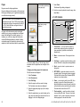
Pixel defect policy
In common with all TFT units, the screen may exhibit
a few wrongly-illuminated (“dead”) pixels. These may
appear as black pixels in a light area of the screen or as
colored pixels in black areas.
If your display exhibits MORE than the number of
wrongly-illuminated pixels stated below, please contact
your local Raymarine service center for further advice.
5
Maximum
acceptable
wronglyilluminated pixels
e7 / e7D
c95 / c97 / c125 /
c127 / e95 / e97 /
e125 / e127
7
8
Warranty registration
To register your Raymarine product ownership, please
visit www.raymarine.com and register online.
It is important that you register your product to receive
full warranty benefits. Your unit package includes a
bar code label indicating the serial number of the unit.
You will need this serial number when registering your
product online. You should retain the label for future
reference.
IMO and SOLAS
The equipment described within this document is
intended for use on leisure marine boats and workboats
not covered by International Maritime Organization
(IMO) and Safety of Life at Sea (SOLAS) Carriage
Regulations.
Technical accuracy
To the best of our knowledge, the information in this
document was correct at the time it was produced.
However, Raymarine cannot accept liability for any
inaccuracies or omissions it may contain. In addition,
our policy of continuous product improvement may
change specifications without notice. As a result,
Raymarine cannot accept liability for any differences
between the product and this document. Please
check the Raymarine website (www.raymarine.com) to
ensure you have the most up-to-date version(s) of the
documentation for your product.
6
e7 / e7D / e95 / e97 / e125 / e127 / c95 / c97 / c125 / c127
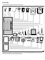
System integration
Your multifunction display is compatible with a wide range of marine electronics devices.
1
2
3
5
4
P
IT
L
O
7
6
8
SMARTPILOT
RAY240
9
17
10
18
11
12
13
15
14
21
19
20
16
22
D12244-1
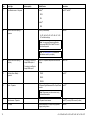
The display uses a number of protocols to transfer data between the various devices in your system. The following table details which devices may be connected to your
display, and the type of connections (in terms of protocols and physical interfaces):
7
Item
Device Type
Maximum quantity
Suitable Devices
Connections
1
Remote control
1 per multifunction display.
Raymarine RCU-3
Bluetooth
2
Smartphone
1 per multifunction display.
For chartplotter sync with Navionics Marine app:
• Chartplotter sync with Navionics Marine app: WiFi.
• Apple iPhone or iPad.
• Video streaming: WiFi.
• Android-compatible smartphone.
• Media player control: Bluetooth AVRCP 2.1 or later.
For smartphone media player control:
• Any Bluetooth-enabled smartphone supporting
Bluetooth AVRCP version 2.1 or higher.
For wireless video streaming:
• Apple iPhone 4 (or later) or iPad (requires the
“Raymarine Viewer” video streaming app, available
from the Apple App Store).
3
Vessel tank sensors — third-party
• Up to 3 x fuel.
Third-party NMEA 2000 interfaces.
NMEA 2000 (via optional DeviceNet adaptor cables).
Any combination of the following:
SeaTalk, SeaTalkng, or NMEA 0183.
• 1 x fresh water.
• 1 x waste water.
• 1 x sewage.
• 1 x bait / fish.
4
GPS (external) — Raymarine
1
• Raystar125 GPS.
• Raystar125+ GPS (via optional SeaTalk to SeaTalkng
converter).
8
e7 / e7D / e95 / e97 / e125 / e127 / c95 / c97 / c125 / c127
Item
Device Type
Maximum quantity
Suitable Devices
Connections
5
Instruments — Raymarine
As determined by SeaTalkng bus
bandwidth and power loading.
SeaTalk (via optional SeaTalk to SeaTalkng converter):
SeaTalk, SeaTalkng.
• ST40 Wind, Speed, Depth, Rudder, or Compass.
• ST60 Wind, Speed, Depth, Rudder, or Compass.
SeaTalkng:
• ST70.
• ST70+.
• ST70+ keypads.
• i70.
5
Instruments — third-party
• Connections to multifunction
display NMEA outputs: 4.
NMEA 0183–compatible instruments.
NMEA 0183
SeaTalk (via optional SeaTalk to SeaTalkng converter)::
SeaTalk, SeaTalkng.
• Connections to multifunction
display NMEA inputs: 2
6
Pilot control heads — Raymarine
As determined by SeaTalk or
SeaTalkng bus bandwidth and power
loading, as appropriate.
• ST6002.
• ST7002.
• ST8002.
SeaTalkng:
• ST70.
• ST70+.
• p70.
• p70R.
6
Pilot control heads — third-party
1
NMEA 0183–compatible instruments.
NMEA 0183
9
Item
Device Type
Maximum quantity
Suitable Devices
Connections
7
Course computer — Raymarine
1
SeaTalk (via optional SeaTalk to SeaTalkng converter):
SeaTalk, SeaTalkng, or NMEA 0183.
• ST1000.
• ST2000.
• S1000.
• S1.
• S2.
• S3.
SeaTalkng:
• All SPX course computers.
7
Course computer — third-party
1
NMEA 0183 or NMEA 2000 compatible course computer.
NMEA 0183 or NMEA 2000 (via optional DeviceNet
adaptor cables).
8
AIS — Raymarine
1
• AIS 250.
SeaTalkng, or NMEA 0183.
• AIS 500.
• AIS 350.
• AIS 650.
• AIS 950
8
AIS — third-party
1
Third-party NMEA 0183–compatible AIS Class A or Class
B receiver / transceiver.
NMEA 0183
9
Vessel trim tabs — third-party
1 pair
Third-party NMEA 2000 interfaces.
NMEA 2000 (via optional DeviceNet adaptor cables).
10
Video / camera
• e7 / e7D / c95 / c97 / c125 / c127
=1
Composite PAL or NTSC video source.
BNC connectors.
• e95 / e97 / e125 / e127 = 2
11
Lifetag (Man overboard alert)
1 basestation
All Raymarine Lifetag basestations.
SeaTalk (via optional SeaTalk to SeaTalkng converter)
12
Engine interface — third-party
1
Third-party NMEA 2000 interfaces.
NMEA 2000 (via optional DeviceNet adaptor cables).
10
e7 / e7D / e95 / e97 / e125 / e127 / c95 / c97 / c125 / c127
Item
Device Type
Maximum quantity
Suitable Devices
Connections
13
Transducers and sensors —
Raymarine
1
Analog transducers:
SeaTalkng (via optional transducer pods).
• Wind.
• Speed.
• Depth.
13
Transducers and sensors — Airmar
1
• DT800 Smart Sensor.
SeaTalkng (via optional transducer pods).
• DST800 Smart Sensor.
• PB200 weather station.
14
Video out
e95 / e97 / e125 / e127 = 1
External display.
Component
15
Sonar transducer
1
Direct connection to display (Sonar variant displays only):
Raymarine transducer connection, OR Minn Kota
transducer connection.
• Raymarine P48.
• Raymarine P58.
• Raymarine P74.
• Raymarine B60 20º
• Raymarine B60 12º
• Raymarine B744V
; OR:
• Any 600 watt / 1Kw compatible transducer (via optional
E66066 adaptor cable).
; OR:
• Any Minn Kota transducer (via optional A62363 adaptor
cable).
Connection via external Raymarine Sonar Module:
• Any sonar module-compatible transducer.
16
VHF radio — Raymarine
1
All Raymarine DSC VHF radios.
NMEA 0183 only (No SeaTalk support).
11
Item
Device Type
Maximum quantity
Suitable Devices
Connections
17
Sirius Weather receiver — Raymarine
1
SeaTalkhs:
SeaTalkhs, SeaTalkng.
• SR100.
• SR6.
SeaTalkng:
• SR50.
18
Additional multifunction display(s) —
Raymarine
5
SeaTalkhs (recommended):
SeaTalkhs.
• e7 / e7D / e95 / e97 / e125 / e127 / c95 / c97 / c125 /
c127 multifunction display.
Note: You can connect Raymarine multifunction
displays using NMEA 0183 or SeaTalkng but not all
functions are supported.
Note: Visit www.raymarine.com to download the
latest software version for your display.
18
Additional multifunction display(s) —
third-party
• Connections to multifunction
display NMEA outputs: 4.
NMEA 0183–compatible chartplotters and multifunction
displays.
NMEA 0183
• CP450C
SeaTalkhs.
• Connections to multifunction
display NMEA inputs: 2
19
Fishfinder (Sonarr Module) —
Raymarine
1
• DSM 30.
• DSM 300.
20
Radar — Raymarine
1
All Raymarine Digital Radomes and HD or SuperHD radar
scanners.
SeaTalkhs.
Note: Please ensure your radar scanner is using
the latest software version.
21
Thermal camera — Raymarine
1
All Raymarine thermal cameras.
SeaTalkhs (for control), BNC connector (for video).
22
PC / laptop
1
Windows-compatible PC or laptop running Raymarine
Voyager planning software.
SeaTalkhs
12
e7 / e7D / e95 / e97 / e125 / e127 / c95 / c97 / c125 / c127
Item
Device Type
Suitable Devices
Connections
Cartography — included
Maximum quantity
Embedded (internal) Navionics world base map.
Internal storage.
Cartography — optional
External MicroSD, or MicroSDHC chart cards:
Card slot.
• Navionics Ready to Navigate.
• Navionics Silver
• Navionics Gold
• Navionics Gold+
• Navionics Platinum
• Navionics Platinum+
• Navionics Fish’N Chip
• Navionics Hotmaps
Refer to the Raymarine website (www.raymarine.com) for
the latest list of supported chart cards.
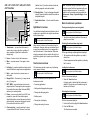
Location and mounting
Selecting a location
General location requirements
When selecting a location for your display it is important
to consider a number of factors.
Key factors which can affect product performance are:
• Ventilation
To ensure adequate airflow:
– Ensure that equipment is mounted in a
compartment of suitable size.
– Ensure that ventilation holes are not obstructed.
Allow adequate separation of equipment.
Any specific requirements for each system
component are provided later in this chapter.
• Mounting surface
Ensure equipment is adequately supported on a
secure surface. Do not mount units or cut holes in
places which may damage the structure of the vessel.
• Cable entry
Ensure the unit is mounted in a location which allows
proper routing and connection of cables:
GPS location requirements
– Minimum bend radius of 100 mm (3.94 in) unless
otherwise stated.
In addition to general guidelines concerning the
location of marine electronics, there are a number
of environmental factors to consider when installing
equipment with an internal GPS antenna.
– Use cable supports to prevent stress on connectors.
Mounting location
• Water ingress
The display is suitable for mounting both above and
below decks. It is waterproof to IPX6 standard.
Although the unit is waterproof, it is good practice to
locate it in a protected area away from prolonged and
direct exposure to rain and salt spray.
• Electrical interference
Select a location that is far enough away from
devices that may cause interference, such as motors,
generators and radio transmitters / receivers.
• Above Decks mounting:
Provides optimal GPS performance. (For equipment
with appropriate waterproof rating.)
• Below Decks mounting:
GPS performance may be less effective and may
require an external GPS antenna mounted above
decks.
• Power supply
Select a location that is as close as possible to the
vessel’s DC power source. This will help to keep
cable runs to a minimum.
13
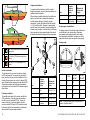
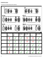
Compass safe distance
When choosing a suitable location for the multifunction
display you should aim to maintain the maximum
possible distance between the display and any
compasses. Typically this distance should be at least
1 m (3 ft) in all directions. However for some smaller
vessels it may not be possible to locate the display this
far away from a compass. In this situation, the following
figures provide the minimum safe distance that should
be maintained between the display and any compasses.
1
2
2
6
2.
In this location, GPS performance may be less
effective.
Left-hand side
250 mm (9.84 in.)
Viewing angle considerations
As display contrast, color and night mode performance
are all affected by the viewing angle, Raymarine
recommends you temporarily power up the display
when planning the installation, to enable you to best
judge which location gives the optimum viewing angle.
250
(9.8 mm
4 in
)
200
(7.8 mm
7 in
)
mm
500.7 in)
(19
000000
This location provides optimal GPS performance
(above decks).
6
Viewing angle
D11537-2
1.
700 mm (27.5 in.)
B
A
000000
This location is NOT recommended for GPS
antenna.
000000
3.
mm
700.5 in)
(27
C
350
(13 mm
.8 in
)
300
(11 mm
.8 in
)
D
000
3
Front
000
1
5
000
3
Minimum safe
distance from
display
000
2
Item
000000
1
Compass
position in
relation to
display
000
To prevent potential interference with the vessel’s
magnetic compasses, ensure an adequate distance is
maintained from the display.
3
000
Vessel construction
5
D12268-1
The construction of your vessel can have an impact
on GPS performance. For example, the proximity of
heavy structure such as a structural bulkhead, or the
interior of larger vessels may result in a reduced GPS
signal. Before locating equipment with an internal GPS
antenna below decks, seek professional assistance
and consider use of an external GPS antenna mounted
above decks.
Prevailing conditions
The weather and location of the vessel can affect the
GPS performance. Typically calm clear conditions
provide for a more accurate GPS fix. Vessels at
extreme northerly or southerly latitudes may also
receive a weaker GPS signal. GPS antenna mounted
below decks will be more susceptible to performance
issues related to the prevailing conditions.
14
4
e7 / e7D
e95 / e97 /
c95 / c97
e125 / e127 /
c125 / c127
A
70º
80º
80º
B
70º
80º
80º
C
70º
80º
80º
D
50º
60º
60º
D12203-1
Item
Compass
position in
relation to
display
Minimum safe
distance from
display
1
Top
200 mm (7.87 in.)
2
Rear
500 mm (19.7 in.)
3
Right-hand side
350 mm (13.8 in.)
4
Underside
300 mm (11.8 in.)
Note: The angles stated are for a contrast ratio of
equal to or greater than 10.
e7 / e7D / e95 / e97 / e125 / e127 / c95 / c97 / c125 / c127
Product dimensions
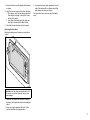
Removing the rear bezel
You must remove the rear bezel before flush-mounting
the display.
C
E
B
1. Remove the front bezel. Refer to the separate
instructions provided for that procedure.
3
D
A
D12269-1
Item
e7 / e7D
e95 / e97 /
c95 / c97
e125 / e127 /
c125 / c127
A
233 mm
(9.17 in.)
290 mm
(11.42 in.)
354 mm
(13.94 in.)
B
144 mm
(5.67 in.)
173 mm
(6.81 in.)
222 mm
(8.74 in.)
C
64 mm (2.52
in.)
64 mm (2.52
in.)
69 mm (2.72
in.)
D
160 mm
(6.29 in.)
160 mm
(6.29 in.)
160 mm
(6.29 in.)
E
180 mm
(7.09 in.)
212 mm
(8.35 in.)
256 mm
(10.08 in.)
1
D12271-1
*
= e 7 / e 7D
*2
= c95 / c97 c125 / c127 / e 95 / e 97 / e 125 / e 127
D12184-2
2. Remove the screws that secure the bezel to the
display.
3. Carefully remove the bezel from the rear of the
display, pulling the bezel gently along the:
i. Outer edges - work from the sides upwards and
then along the top edge, ensuring that the clips
are fully released from the display.
ii. Inner edges - ensure that the bezel is completely
removed from the display.
Flush mounting
You can mount the display in a flush or panel mounting
arrangement.
Before mounting the unit, ensure that you have:
• Selected a suitable location.
• Identified the cable connections and route that the
cables will take.
1. Check the selected location for the unit. A clear,
flat area with suitable clearance behind the panel
is required.
2. Fix the appropriate cutting template supplied with
the product, to the selected location, using masking
or self-adhesive tape.
3. Using a suitable hole saw (the size is indicated on
the template), make a hole in each corner of the
cut-out area.
4. Using a suitable saw, cut along the inside edge of
the cut-out line.
5. Ensure that the unit fits into the removed area and
then file around the rough edge until smooth.
6. Drill 4 holes as indicated on the template to accept
the securing screws.
7. Place the gasket onto the display unit and press
firmly onto the flange.
8. Connect the power, data and other cables to the unit.
9. Slide the unit into place and secure using the
provided screws.
• Detached the front bezel.
15
Note: The appropriate torque to use when drilling
depends on the thickness of the mounting surface
and the type of material.
3. Use the supplied screws to secure the bezel to the
display.
4. Attach the display unit to the mounting bracket.
Bracket (trunnion) mounting
Note: The supplied gasket provides a seal between
the unit and a suitably flat and stiff mounting surface
or binnacle. The gasket should be used in all
installations. It may also be necessary to use a
marine-grade sealant if the mounting surface or
binnacle is not entirely flat and stiff or has a rough
surface finish.
3. Use the supplied screws to attach the mounting
bracket securely.
The display can be mounted on a bracket.
Note: The appropriate torque to use when drilling
depends on the thickness of the mounting surface
and the type of material.
Before mounting the unit ensure that you have:
• Selected a suitable location.
• Identified the cable connections and route that the
cables will take.
• Attach the front bezel.
Front bezel
Attaching the front bezel
The following procedure assumes that the unit has
already been mounted in position.
Attaching the rear bezel
The rear bezel must be fitted before mounting the unit
on the supplied trunnion bracket.
1. Carefully lift one edge of the screen protection
film, so that it is accessible for removing when unit
installation is complete.
1. Remove the front bezel. Refer to the separate
instructions provided for that procedure.
2. Ensure the memory card slot door is in the open
position.
2. Place the bezel over the rear of the display, ensuring
that it is correctly aligned with the display. Apply firm
but even pressure to the bezel along the:
i. Outer edges - work from the sides upwards and
then along the top edge, to ensure that it clips
securely into position.
ii. Inner edges - ensure that the bezel sits flat
against the unit.
3. Orientate the bottom-right side of the bezel under the
lip of the chart card door and place the bezel over
the front of the display, ensuring that the clips along
the bottom edge of the bezel latch into position.
2
1
D12273-1
1. Mark the location of the mounting bracket screw
holes on the chosen mounting surface.
*
= e 7 / e 7D
*3
= c95 / c97 c125 / c127 / e 95 / e 97 / e 125 / e 127
16
D12183-2
2. Drill holes for the screws using a suitable drill,
ensuring there is nothing behind the surface that
may be damaged.
D12274-1
e7 / e7D / e95 / e97 / e125 / e127 / c95 / c97 / c125 / c127
4. Ensure the bezel is correctly aligned with the display,
as shown.
5. Apply firm but even pressure to the bezel along the:
i. Outer edges - work from the sides upwards and
then along the top edge, to ensure that it clips
securely into position.
ii. Inner edges - particularly along the chart card
door edge, to ensure that the bezel sits flat.
6. Check that all control buttons are free to operate.
3. In a single firm motion, apply pressure to the outer
edge of the display with your thumbs and pull the
bezel towards you using your fingers.
The bezel should now come away from the display
easily.
Removing the front bezel
Before proceeding ensure the memory card slot door
is open.
2
2
1
1
D12275-1
Important: Use care when removing the bezel. Do
not use any tools to lever the bezel; doing so may
cause damage.
1. Place both your thumbs on the upper left edge of
the display, at the positions indicated in the diagram
above.
2. Place your fingers underneath the bezel, at the
positions indicated in the diagram above.
17
Connections overview
The connections for all multifunction display variants are listed below.
e7
e 7D
e 95 / e 125
e 97 / e 127
c95 / c125
c97 / c127
D12249-3
SeaTalkhs
Transducer
SeaTalkng
Network 1
/ RayNet
SeaTalkhs
Network 2
/ RayNet
Video in / out
Power / Video / NMEA
0183
e7
e7D
e95
e97
e125
18
e7 / e7D / e95 / e97 / e125 / e127 / c95 / c97 / c125 / c127
SeaTalkng
Transducer
SeaTalkhs / RayNet
Network 1
SeaTalkhs / RayNet
Network 2
Video in / out
Power / Video / NMEA
0183
e127
c95
c97
c125
c127
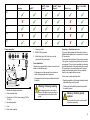
Power connection
7. Video input cable.
Grounding — Dedicated drain wire
8. NMEA 0183 data cables.
The power cable supplied with this product includes a
dedicated shield (drain) wire for connection to a vessel’s
RF ground point.
9. Shield (drain) wire (thin black wire; must be
connected to RF ground point).
Power distribution
4
5
1
Raymarine recommends that all power connections are
made via a distribution panel.
2
3
7
• All equipment must be powered from a breaker or
switch, with appropriate circuit protection.
6
• All equipment should be wired to individual breakers
if possible.
8
9
D12250-1
1. Multifunction display connections.
2. Power and data cable.
3. Connection to 12/24 V power supply (e7/e7D is
12V only).
4. Red cable (positive).
Warning: Product grounding
Before applying power to this product,
ensure it has been correctly grounded, in
accordance with the instructions in this
guide.
It is important that an effective RF ground is connected
to the system. A single ground point should be used for
all equipment. The unit can be grounded by connecting
the shield (drain) wire of the power cable to the vessel’s
RF ground point. On vessels without an RF ground
system the shield (drain) wire should be connected
directly to the negative battery terminal.
The dc power system should be either:
• Negative grounded, with the negative battery terminal
connected to the vessel’s ground.
• Floating, with neither battery terminal connected to
the vessel’s ground
Warning: Positive ground
systems
Do not connect this unit to a system which
has positive grounding.
5. Fuse.
6. Black cable (negative).
19
Power cable
The display is supplied with a combined power and data
multi cable, this can be extended if required.
Power cables available
Cable
Part number
1.5 m (4.9 ft)
Straight power
and data cable
R62379
1.5 m (4.9 ft) Right
angled power and
data cable
R70029
Notes
Breakers, fuses and circuit protection
The power cable includes an in-line fuse. It is
recommended that you fit an additional thermal breaker
or fuse at the distribution panel.
Fuse rating
Thermal breaker rating
7 A in-line fuse fitted within
power cable.
5 A (if only connecting one
device)
The display has 2 NMEA 0183 ports:
• Port 1: Input and output, 4800 or 38400 baud rate.
• Port 2: Input only, 4800 or 38400 baud rate.
Note: The suitable fuse rating for the thermal
breaker is dependent on the number of devices you
are connecting. If in doubt consult an authorised
Raymarine dealer.
Cable extension
The following restrictions apply to any extension to the
power cable:
NMEA 0183 devices are connected using the supplied
power and data cable.
NMEA 0183 connection
• Cable must be of a suitable gauge for the circuit load.
• Each unit should have its own dedicated power cable
wired back to the distribution panel.
Note: The baud rate you want to use for each
port input must be specified in the System
Settings menu (Homescreen:→Set-up→System
Settings→NMEA Set-up→NMEA Input Port).
Note: For Port 1, both the input and output
communicate at the same baud rate. For example, if
you have one NMEA 0183 device connected to the
display’s Port 1 INPUT, and another NMEA 0183
device connected to the display’s Port 1 OUTPUT,
both NMEA devices must be using the same baud
rate.
You can connect up to 4 NMEA 0183 devices to the
display’s NMEA 0183 OUTPUT (Port 1). You can
connect a total of 2 NMEA 0183 devices to the display’s
NMEA 0183 INPUT ports.
Total length
(max)
Supply voltage
Cable gauge
(AWG)
0–5 m (0–16.4 ft)
12 V
18
24 V
20
12 V
14
Item Device
24 V
18
1
12 V
12
2
24 V
16
12 V
12
5–10 m
(16.4–32.8 ft)
10–15 m
(32.8–49.2 ft)
1
15–20 m
(49.2–65.5 ft)
24 V
3
4
5
6
Port
Input /
output
White
1
Input
Positive
Green
1
Input
Negative
3
Yellow
1
Output
Positive
4
Brown
1
Output
Negative
5
Orange
/ white
2
Input
Positive
6
Orange
/ green
2
Input
Negative
14
7
Note: These distances are for a 2 wire power cable run
from the battery to the display (approximately the distance
from the battery to the display). To calculate the round trip
length, double the figure stated here.
20
2
Multifunction
display
Cable
color
Positive (+)
/ negative (-)
8
9
NMEADEVICE
4800 / 38400 baud
10
11
12
NMEADEVICE
4800 / 38400 baud
D12266-2
e7 / e7D / e95 / e97 / e125 / e127 / c95 / c97 / c125 / c127
Port
Input /
output
Positive (+)
/ negative (-)
*
*
Output
Positive
8
*
*
Output
Negative
9
*
*
Input
Positive
10
*
*
Input
Negative
*
*
Output
Positive
Item Device
Cable
color
7
NMEA
device
11
12
NMEA
device
*
*
Output
Negative
Note: *Refer to instructions provided with NMEA
device.
3. To switch the color palette, from the homescreen
select Customize→Display Preferences→Color
Palette.
6
Note: The simulator will NOT display any real data,
including any safety messages (such as those
received from AIS units).
Note: Any system settings made whilst in Simulator
mode are NOT transmitted to other equipment.
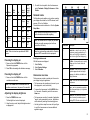
Homescreen overview
1. Press and hold the POWER button until the
countdown reaches zero.
The homescreen provides a central point of access to
your display’s range of applications.
Adjusting the display brightness
1. Press the POWER button once.
The Backlight Level control is displayed.
2. Using the rotary control, adjust the brightness level
as appropriate.
4
Note: Raymarine recommends that you do NOT
use the simulator mode whilst navigating.
Powering the display off
Note: If the POWER button is released before the
countdown reaches zero, the power off is cancelled.
3
The Simulator mode enables you to practice operating
your display without data from a GPS antenna, radar
scanner, AIS unit, or fishfinder.
The simulator mode is switched on / off in the System
Setup Menu.
2. Press OK to acknowledge the disclaimer message.
1. Press and hold the POWER button until the
Raymarine logo appears.
2
Simulator mode
Enabling simulator mode
With the homescreen displayed:
1. Select Set-Up .
2. Select System Settings.
3. Select Simulator.
Powering the display on
1
• The homescreen also provides quick access to your
data (waypoints, routes, and tracks).
D12195-1
Screen item
Description
1
Touch Lock — select this icon to lock the
touchscreen, preventing accidental use. To
unlock, use the UniControl to deselect the
Touch Lock icon (HybrifTouch displays only).
2
My Data — this icon enables you to centrally
manage your lists of routes, tracks, and
waypoints.
3
Customize — select this icon to configure
application pages and select the display’s
language, units, date/time, boat details and
display preferences.
4
Set-up — select this icon to access the system
set-up menus.
5
Page — each icon represents an application
page. A page can display up to 2 applications
simultaneously.
6
Status bar — the status icons confirm the
status of externally-connected equipment,
including GPS, AIS, radar, and autopilot units.
• To access the homescreen, hold the MENU button
for 3 seconds. Alternatively, select the on-screen
Home icon.
• The homescreen consists of a number of application
"pages", each represented by an icon. Applications
can be started by selecting the relevant page icon.
5
• Use the joystick or swipe the screen with your finger
to scroll the homescreen and access additional
application pages.
21
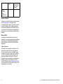
Pages
You can add any application(s)
to any empty page.
Pages are used to display applications.
Pages are displayed and accessed on the homescreen.
Each page can display up to 4 applications (depending
on multifunction display variant).
7. Select Finish.
The Rename Page dialog is displayed.
8. Use the on-screen keyboard to name the page, then
select Save.
e7 / e7D Controls
Note: The e7 and e7D can only configure up to 2
applications per page. The e7/e7D can only display
4 applications per page if connected and to a e9/c9
or e12/c12 which has been configured to show 4
applications per page..
1
Page featuring a single
application.
2
3
4
Any page on the homescreen can be customized,
enabling you to group your applications into different
pages, each designed for a specific purpose. For
example, you could have a page that includes the
chart and fishfinder applications, suitable for fishing,
and another page that includes the chart and data
applications, which would be suitable for general sailing.
5
6
7
Page featuring multiple
applications.
D12179-1
1. Touchscreen — you can touch the screen to
operate many common functions, including all
menu operations (HybridTouch multifunction
displays only).
2. Menu — accesses menus. Press again to close
menus.
You can also define a "layout" for each page, which
determines how the applications are arranged on the
screen.
Changing an existing page on the homescreen
With the homescreen displayed:
1. Select Customize.
2. Select Homescreen.
3. Select Edit Page.
4. Select the page icon that you want to change.
The Customize menu options are displayed.
5. Select the appropriate page layout (for example,
“Splitscreen”).
6. Select the application(s) you want to display on the
page, either by selecting the relevant menu item or
dragging it over to the displayed page.
22
3. UniControl — provides a joystick and rotary control
and an OK button for using menus and applications.
4. Back — press to return to a previous menu or
dialog level.
5. WPT / MOB — press and release to access the
waypoint options. Press again to place a waypoint.
Press and hold to place a Man Overboard (MOB)
marker at your current position.
6. Power — press once to switch the unit ON. Once
powered on, press the Power button again to
adjust the brightness, access the power controls for
external devices, and access the autopilot controls.
Press and hold to switch the unit OFF.
7. Chart card slots — open the card door to insert
or remove MicroSD cards. There are 2 card slots
(labelled 1 and 2), used for electronic charts and
archiving waypoint, route and track data.
e7 / e7D / e95 / e97 / e125 / e127 / c95 / c97 / c125 / c127
c95 / c97 / c125 / c127 / e95 / e97 / e125 /
e127 Controls
2
1
(labelled 1 and 2), used for electronic charts and
archiving waypoint, route and track data.
10. Standby (Auto) — Press to disengage integrated
autopilot, press and hold to activate Auto mode on
integrated autopilot.
3
4
11. Switch Active Pane — Press to switch the active
pane.
5
6
7
8
Hybridtouch overview
Your multifunction display features Hybridtouch, which
enables you to operate the unit using the touchscreen
and the physical keys.
This only applies to HybridTouch displays.
11
10
9
D12276-1
2. Home — Press to return to the homescreen.
Many common functions can be accessed using the
touchscreen. However, there may be situations (such
as rough sea conditions) when it is not appropriate to
use the touchscreen. In these situations, Raymarine
strongly recommends that you activate the touch lock
and use the physical keys to operate your multifunction
display.
3. Menu — accesses menus. Press again to close
menus.
Touchscreen overview
4. UniControl — provides a joystick and rotary control
and an OK button for using menus and applications.
The touchscreen provides a quick way of performing
many common functions.
1. Touchscreen — you can touch the screen to
operate many common functions, including all
menu operations (HybridTouch multifunction
displays only).
5. Back — press to return to a previous menu or
dialog level.
Placing and moving the cursor using touch
This only applies to HybridTouch displays.
1. Touch the screen at any position on the screen to
place the cursor there.
Selecting the active window using touch
This only applies to HybridTouch displays.
With a page featuring multiple applications displayed:
1. Tap anywhere inside the application you want to
make active.
A border appears around the application, indicating
that it is active.
Locking the touchscreen
This only applies to HybridTouch displays.
With the homescreen displayed:
Some of the functions you can operate with the
touchscreen include:
7. WPT / MOB — press and release to access the
waypoint options. Press again to place a waypoint.
Press and hold to place a Man Overboard (MOB)
marker at your current position.
• Accessing applications.
9. Chart card slots — open the card door to insert
or remove MicroSD cards. There are 2 card slots
Basic touchscreen operations
This only applies to HybridTouch displays.
6. Range In/Out — Press minus (-) to range out and
plus (+) to range in
8. Power — press once to switch the unit ON. Once
powered on, press the Power button again to
adjust the brightness, access the power controls for
external devices, and access the autopilot controls.
Press and hold to switch the unit OFF.
Note: Raymarine strongly recommends that you
familiarize yourself with touch operations while your
vessel is anchored or moored. You may find it
helpful to use the simulator mode (accessible from
Homescreen→Set-up→System Settings) in these
situations.
1. Select the Touch Lock icon.
It changes color to indicate that the touchscreen is
disabled. All functions are still available using the
buttons and UniControl.
• Adding and editing applications pages.
• Placing and editing waypoints.
• Building routes.
• Panning the chart display.
• Placing and moving the cursor.
Unlocking the touchscreen
This only applies to HybridTouch displays.
With the homescreen displayed:
1. Use the UniControl to highlight the Touch Lock icon.
2. Press the OK button.
The Touchscreen is enabled.
23
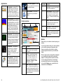
Applications
Chart application — provides a 2D or
3D graphical view of your charts to help
you navigate. Waypoint, route, and track
functions enable you to navigate to a
specific location, build and navigate routes,
or record where you’ve been. Chart cards
provide higher levels of detail and 3D views.
Fishfinder application — with a transducer
and a sonar variant multifunction display or
compatible Sonar Module, you can use the
fishfinder application to help you accurately
distinguish between different sizes of
fish, bottom structure, and underwater
obstacles. You can also view sea depth
and temperature data and mark points of
interest such as fishing spots or wrecks.
Thermal camera application — view and
control a compatible thermal camera using
your multifunction display.
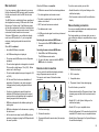
Screen item
Description
4
Pop-up menu — menu options are displayed
when you select the Menu icon.
Video application — view a video or
camera source on your multifunction
display.
5
Pop-up messages — alert you to a situation
(such as an alarm), or unavailable function.
Pop-up messages may require a response
from you — for example, select OK to silence
alarms.
6
Dialogs — enable data to be selected, edited
or entered. Use in many common functions —
for example, editing a waypoint..
7
Context menu — provides information and
options specific to each application.
8
Status bar — provides information specific to
each application. This information cannot be
edited or moved.
Screen overview
1
2
3
8
4
7
Radar application — with a suitable radar
scanner, you can use the radar application
to track targets and measure distances
and bearings. A number of automatic gain
presets and color modes are provided to
help you get the best performance from
your radar scanner.
Data application — view system and
instrument data on your multifunction
display, for a range of compatible
instruments. Use the joystick or
touchscreen to scroll through the available
data pages.
Weather application — (North America
only). With a suitable weather receiver
connected to your system, the weather
application overlays historical, live, and
forecasted weather graphics on a world
map.
24
6
Alarms
5
D12196-1
Alarms alert you to a situation or hazard requiring your
attention.
Screen item
Description
You can set up alarms to alert you to certain conditions,
such as collision warnings and temperature limits.
1
Home — select this icon to access the
homescreen.
Alarms are raised by system functions, and also
external equipment connected to your multifunction
display.
2
Databar — provides information about
your vessel and its environment. The
position and type of information in the
databar can be customized from the
Homescreen→Customize →Databar
Set-up menu, if required.
When an alarm sounds a message dialog is displayed
on your multifunction display and any networked
displays. The dialog states the reason for the alarm.
3
Menu — select this icon to access the
menu. The menu options are specific to the
application that you are currently using. Use
the touchscreen (HybridTouch displays only)
or use the Rotary control to select menu items
and scroll long menus.
You can configure the behavior of certain alarms
by selecting the Edit option on the message dialog
or by using the Alarms menu, accessible from the
homescreen via the Set-Up icon.
e7 / e7D / e95 / e97 / e125 / e127 / c95 / c97 / c125 / c127
Man overboard
When the MOB alarm is cancelled:
To use the remote control you must first:
If you lose a person or object overboard, you can use
the Man Overboard (MOB) function to mark the position
that the vessel was at when the MOB function was
activated.
The MOB function is available at all times, regardless of
which application is running. MOB can be set to Dead
Reckoning or Position mode. Dead Reckoning mode
will take into consideration the effects of wind and tides.
This usually provides a more accurate course. Position
mode does not take these factors into account.
To obtain a MOB position, your multifunction display
must have a GPS position fix. If you’re using dead
reckoning, heading and speed data must also be
available.
When MOB is activated:
• MOB data is removed from the relevant applications.
• Enable Bluetooth in the System Settings on the
multifunction display.
• An audible MOB alarm is sounded.
• An MOB alarm dialog box is displayed.
• The system sends MOB alarms to other Raymarine
equipment.
• The chart application motion mode is reset.
• GOTO and route functions are restored.
Video streaming connection
• The databar mode is reset.
You can use compatible tablet and smartphone devices
as a wireless repeat display.
• A MOB normal mode signal is sent to any instrument
on SeaTalk.
Activating the man overboard (MOB) alarm
1. Press and hold the WPTS / MOB button for 3
seconds.
Remote control connection
• The active radar application range is changed to 230
m (760 ft).
You can control the multifunction display wirelessly
using a Raymarine remote control unit.
The remote control uses a Bluetooth wireless
connection.
1
3
4
D12165-2
2. Wi-Fi connection.
3. Compatible device.
4. “Raymarine Viewer” video streaming app.
1
2
3
To use this feature you must first:
• Download and install the “Raymarine Viewer” video
streaming app, available from the relevant market
store.
• Enable Wi-Fi in the System Settings on the
multifunction display.
• MOB data is displayed in the databar, replacing the
existing data.
• As the vessel moves away from the MOB position a
dotted line is displayed, joining the MOB position with
the vessel’s position.
2
1. Multifunction display.
• If position or heading and speed information is
available a MOB waypoint is placed at the current
vessel position in any application that is capable of
showing waypoints and vessel position.
• MOB data is displayed on the homescreen, replacing
the status icons.
This feature enables you to stream what you see on
your multifunction display to compatible device, using a
WiFi connection.
Cancelling the man overboard (MOB) alarm
1. Select OK on the MOB alarm dialog.
The MOB alarm remains active.
2. To cancel the alarm, press and hold the WPTS /
MOB button for 4 seconds.
• The active chart application is changed to a low-detail
2D view, with an initial range of 15 m (50 ft). Motion
mode is set to Auto Range.
• All Goto and Follow functions are disabled in all
applications. Navigation to any active waypoint
is stopped and any existing navigation function is
cancelled.
• Pair the remote control unit with the multifunction
display.
• The chart is centered on the vessel and pitch /
rotation set to default.
D12163-2
1. Multifunction display.
• Enable Wi-Fi on your compatible device.
2. Bluetooth connection.
• Select the Raymarine Wi-Fi connection from the list of
available Wi-Fi networks on your compatible device.
3. Raymarine Bluetooth remote control (for example,
RCU-3).
• Enable Device Streaming in the System Settings on
the multifunction display.
25
Navionics chartplotter sync connection
You can wirelessly synchronize waypoints and routes
between the multifunction display and a tablet or
smartphone device.
1
2
3
4
D12166-2
1. Multifunction display.
2. Wi-Fi connection.
3. Tablet / smartphone.
4. Navionics Marine app.
To use this feature you must first:
• Download and install the Navionics Marine app,
available from the relevant app store.
• Enable Wi-Fi in the System Settings on the
multifunction display.
• Enable Wi-Fi on your tablet / smartphone.
• Select the Raymarine Wi-Fi connection from the list of
available Wi-Fi networks on your tablet / smartphone.
26
e7 / e7D / e95 / e97 / e125 / e127 / c95 / c97 / c125 / c127
www.ra ym a rin e .c o m