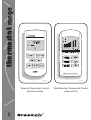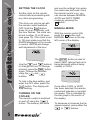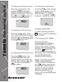
1
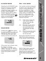
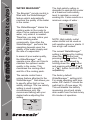
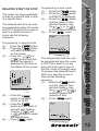
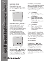
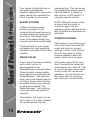
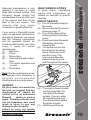
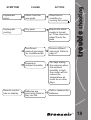
®
REMOTE CONTROL
AUTO
COOL
PM
FAN
SPEED
ECONOMY
BATTERY LOW
owner’s manual
Breezair ® coolers have been
designed to provide quiet,
reliable and cool comfort.
At Seeley International we
®
manufacture Breezair
evaporative coolers from the
highest quality materials, and we
have designed the product to
provide many years of
economical, trouble free cooling.
Please take a few moments to
read these operating
instructions, so that the most can
be gained from this investment.
®
The appliance
is not intended for
use by young children or infirm
persons without supervision;
young children should be
supervised to ensure they do not
play with the appliance.
Breezair coolers are fitted with
either a Wall Mounted
Thermostat Control or a Remote
Thermostat Control. Please refer
to the relevant section in this
manual for instructions on how to
operate either system. Also,
please be aware of the
components and features that
are fitted to your particular
cooler.
introduction page
Hello and congratulations on
purchasing a Breezair ® Ducted
Cooler for your home.
EFFECTIVE COOLING
To provide efficient cooling or
ventilation the building must
have sufficient exhaust
openings to the outside of the
building. To assist air flow, open
windows and doors that are
farthest from the outlet vent in
each room. In these rooms,
provide an exhaust opening
about 2 times the vent size of the
room.
Where the design of the building
prevents adequate exhaust,
consideration should be given to
the provision of mechanical
extractions, such as an exhaust
fan.
Important Notes!
In areas where temperatures
can cause water supply pipes to
freeze, a drain down facility
should be provided during the
installation.
This drain down facility must be
activated prior to freezing
conditions, to avoid possible
damage to the cooler
components.
If the supply cord is damaged, it
must be replaced with a special
cord available from the
manufacturer or its service
agents.
Keep these instructions in a safe
place for future reference.
®
2
thermostat range
REMOTE CONTROL
AUTO
COOL
PM
FAN
SPEED
ECONOMY
ILL239-D
Remote Thermostat Control
(remote control)
3
®
ILL1140-A
Wall Mounted Thermostat Control
(wall control)
contents page
Remote Thermostat Control..............5
Wall Mounted Thermostat Control...11
Bleed Funnel & Drain Valve............15
Power Outages...............................15
Seasonal Maintenance...................16
Troubleshooting..............................18
Service & Warranty.........................20
®
4
remote thermostat control
SETTING THE CLOCK
Set the clock on the remote
control before proceeding with
any other programming.
The clock can only be set with
the remote control switched
OFF. Hold the
button
down for over 2 seconds, until
the hour flashes. The clock can
be set to either 12 or 24 hours
(see page 10). If the clock is set
to 12 hours make sure that the
AM/PM displayed on the screen
is correct. AM/PM will change
with adjustment of the hour.
MANUAL MODE
With the remote control ON,
press the
button until
MANUAL is shown in the top
left corner of the display.
MANUAL
COOL
FAN
SPEED
PM
ILL1108-A
ILL1104-A
Use the
and
buttons
to change the hour. To change
minutes, press the
button
again. Change the minutes
using the
and
buttons.
To lock in the time setting, and
enter the OFF state, press the
button. The display will
stop flashing.
TURNING ON THE
COOLER
The remote control is switched
on and off using the
button. The memory will store
5
and use the settings from when
the cooler was last used. Once
the remote control is on, you
can choose between MANUAL,
AUTO and AUTO TIMER
modes by pressing the
button.
®
The
button is used to
select VENT (where fresh air is
being delivered without being
cooled) or COOL.
MANUAL
VENT
FAN
SPEED
ILL1109-A
Once either COOL or VENT
has been selected, the remote
control will maintain a constant
fan speed. This is indicated by
the bar graph in the centre of
the display.
To decrease or increase the fan
speed required, press either the
or
buttons.
The remote control contains a
thermostat. In AUTO mode the
cooler is controlled
automatically, based on your
pre-selected comfort level. The
cooler will adjust the fan speed,
switch between COOL and
VENT and turn itself off.
However, the sequence and
regularity at which these
settings change will differ with
each operation of the cooler.
As the remote control senses
room conditions, the comfort
control settings will be
influenced by heat from direct
sunlight or electrical appliances.
Likewise placing the remote
control in cupboards or drawers
or under cooling vents will affect
the cooler’s operation.
To set the AUTO mode press
the
button until AUTO is
displayed.
indicating a level between 1
and 10. WARMER or COOLER
will be displayed on the screen
as settings are changed.
AUTO TIMER MODE
AUTO TIMER mode can be
selected by using the
button. Once the AUTO TIMER
mode is selected the cooler will
only operate during the
programmed time period.
Programming the timer must be
performed before AUTO TIMER
can be activated. This can be
done while in any mode, even
when it is OFF. There are 7
steps involved in setting the
AUTO TIMER.
NOTE: After pressing the
button the display will revert
back to the previous setting if
no buttons are pressed within 4
seconds.
To program the timer use the
following sequence:
AUTO
PM
FAN
SPEED
remote thermostat control
AUTO MODE
(1) Setting the ON time hour
ILL1105-A
Ten levels of comfort are
available with the remote
control. While in AUTO mode
pressing the
and
buttons will adjust the level of
required comfort. The display
will show your selection by
®
Begin by pressing the
button. The hour displayed will
start flashing and the word ON
will appear on the screen. Then
use the
and
buttons
to change the hour value.
AUTO
TIMER
ON
ILL1112-A
6
remote thermostat control
(2) Setting the ON time minutes
(5) Setting the comfort level
Press the
button. The
minutes displayed will start
flashing and the word ON will
appear on the screen. Then use
the
and
buttons to
change the minute setting.
Press the
button and the
comfort level number (1 to 10)
displayed will start flashing.
Then use the
and
buttons to change this setting.
AUTO
TIMER
AUTO
TIMER
ON
ILL1116-A
ILL1113-A
(6) Setting ECONOMY
(3) Setting the OFF time hour
Press the
button. The
hour displayed will start flashing
and OFF will be displayed. Then
use the
and
buttons
to change the hour.
AUTO
TIMER
OFF
ILL1114-A
(4) Setting the OFF time minutes
Press the
button. The
minutes displayed will start
flashing and the word OFF will
appear. Then use the
and
buttons to change the
minute setting.
AUTO
TIMER
OFF
ILL1115-A
7
®
To select economy press the
button so that it is displayed
on the screen.
(7) Activating AUTO TIMER
Now that you have
programmed the settings for
AUTO TIMER they will be
stored in the remote control’s
memory until you change them.
Press the
button until
AUTO TIMER is displayed on
the screen. Your cooler will now
only operate during the
programmed time period.
NOTE: To change any AUTO
TIMER settings when the
remote control is switched off,
the
button needs to be
pressed and released within 1
second. To change settings
when the remote control is
turned on press the
button until the desired number
is flashing.
PRE - COOL MODE
Selecting the ECONOMY mode
limits the maximum available
cooling or ventilation and
reduces the power used by up
to 20%. The ECONOMY
function can be used in either
AUTO or MANUAL modes. To
select this mode press the
button so that ECONOMY
appears on the display.
Your remote control is designed
to allow for the saturation of the
cooler’s cooling pads before
the fan is switched on. This
function, referred to as PRECOOL mode, is enabled at DIP
switch D (refer to page 10).
Once it is enabled the cooler,
when first switched on, will
operate as follows:
MANUAL
COOL
PM
FAN
SPEED
ECONOMY
ILL1125-A
DRAIN MODE
Pressing the
button opens
the drain valve in the cooler and
empties the water in the tank.
This will leave the tank clean
and dry and turn the cooler off.
remote thermostat control
ECONOMY MODE
(1)...... If the tank is empty the
drain system will be
closed. The tank will
then be filled.
(2)...... After 60 seconds of the
tank filling with water,
the pump will turn on
and saturate the filter
pads.
(3)...... After the pump has been
running for 3 minutes
the fan will start.
During this operation the word
PRE-COOL will be displayed
on the remote control’s screen.
MANUAL
COOL
PM
DRAIN TANK
ILL1107-A
FAN
SPEED
PRE-COOL
ECONOMY
If the cooler has not been used
for 3 days or 3 hours,
depending on the DIP switch
setting - see page 10, the tank
will automatically be drained to
ensure the system remains
clean.
ILL1142-A
NOTE: PRE-COOL mode will
not be activated if VENT is
selected on the remote control
or the cooler is used again
shortly after having been turned
off.
®
8
remote thermostat control
WATER MANAGER
®
The Breezair ® remote control is
fitted with the WaterManager ®
feature which automatically
monitors the quality of the water
in the cooler.
MANUAL
COOL
®
The WaterManager drains the
existing water in the cooler to
allow it to be replaced with fresh
water, only when it is needed.
Therefore, you may notice your
cooler draining water
occasionally. How often the
WaterManager ® performs this
operation depends upon the
quality of the water supply and
the rate of evaporation.
In areas of poor water quality,
the WaterManager ® will
operate more often as it tries to
maintain the optimum water
quality in the cooler. This
maximises the cooling effect
and life of the cooling pads.
The remote control has a
unique feature attached to the
WaterManager ® that allows you
to specify either high or low
salinity settings. The low salinity
setting is used in specific
circumstances only. We
recommend talking with your
dealer before adjusting this
setting.
MANUAL
COOL
FAN
SPEED
ECONOMY
ILL1111-A
9
The high salinity setting is
designed to operate the cooler
at a maximum safe salinity
level to maintain a normal
working life. It also results in a
minimum usage of water .
®
PM
FAN
SPEED
ECONOMY
ILL1110-A
NOTE: High salinity outlet
water should not be used on
salt sensitive grass or plants. It
has a high salt content.
The current WaterManager ®
setting is displayed by holding
down the
button and
pressing the
button. The
setting can be changed by
holding down the
button
and pressing either the
or
button for HI and LO
respectively.
The factory default
WaterManager ® setting is HI.
For areas operating with bore
water, DIP switch F should be
switched to off (see page 10).
This will disable the salinity
measuring circuit and simply
drain water from the tank every
65 minutes of operation.
DIP SWITCHES
The remote control requires 3
AAA batteries. The use of good
quality alkaline batteries is
recommended. Under normal
conditions a set of batteries will
operate for 12 months. We
recommend that you replace the
batteries before each season.
Do not use rechargeable
batteries as their voltage rating
is too low for the remote control.
There are 2 rows of DIP switches
located under the battery cover
on the remote control.
When the batteries are getting
low on power, BATTERY LOW is
displayed on the screen (the
cooler may also switch off while
the display remains ON). This
indicates that the batteries have
only a small amount of life
remaining.
AUTO
COOL
remote thermostat control
BATTERIES
WARNING: Do not alter DIP
switches 1 to 10 as the cooler
will cease to work.
1 2 3 4 5 6 7 8
ON
OFF
A B C D E F 9 10
ON
OFF
EXAMPLE ONLY
ILL217-G
Definition of DIP switch positions
(first 6 in bottom row only) are as
follows:
PM
FAN
SPEED
BATTERY LOW
ILL1106-A
To change the batteries remove
the cover from the back of the
remote control. Pull out the old
batteries and replace them all
with the new ones. Do not mix
new batteries with old batteries.
The remote control has 2 mins.
of back-up power to retain its
memory while the batteries are
being changed. If this time is
exceeded, turn the power off to
the cooler and wait until the
screen goes blank. Restore the
power and fit the batteries within
4 minutes.
(A)...... Reserved for later use.
(B)...... OFF, 24 hour clock.
ON, 12 hour clock.
(C)...... OFF, 1100 / 1500W
motor.
ON, 380 / 550 / 750W
motor.
(D)...... OFF, no pre-cool.
ON, pre-cool.
(E)...... OFF, drains 3 days after
power off.
ON, drains 3 hours after
power off.
(F)...... OFF, drains every 65
minutes of operation.
ON, activates water
salinity circuit
(WaterManager ®).
®
10
wall mounted thermostat control
11
TURNING THE COOLER
ON
The wall control can be
switched on and off by pressing
the
button. The wall
control will remember the
previous setting it was in when
the cooler was last used.
PREPARING TO START
Whenever you select AUTO
mode or COOL in MANUAL
mode, the cooler will take a few
minutes to start as it fills with
water and saturates the cooling
pads. The time will be
decreased if the tank is full or
the cooler has only recently
been turned OFF. During this
time PREPARING TO START
will flash on the display.
ILL1123-A
Once COOL or VENT has been
selected, the wall control will
maintain a constant fan speed.
This is indicated by the bar
graph shown on the display.
To increase or decrease the fan
speed required, press either
the
or
button.
AUTO MODE
To select the AUTO mode press
the
button until AUTO
is shown on the display.
MANUAL MODE
With the wall control switched
ON, press the
button
until MAN is shown on the
display.
ILL1124-A
ILL1122-A
You may then press the
button to switch between COOL
and VENT (where fresh air is
being delivered but not cooled).
®
In AUTO mode the cooler will
remember the last setting used
and try to achieve this. It may
vary depending on the day’s
conditions. Press the
button if you require more cool
air or the
button if you
require less. Don’t alter the
setting however, until the room
temperature has stabilised.
The cooler can be programmed
to start at a specific time or stop
at a specific time.
The delayed start time can only
be programmed when the cooler
is OFF. To program the cooler to
start in a certain amount of
hours use the following
sequence:
Programming in manual mode
(1)...... Press the
button.
(2)...... Press the
button
until MAN is displayed
on the screen.
(3)...... Press the
or
button until the
desired fan speed is
displayed by the bars in
the middle of the screen.
ILL1118-A
(4)...... Press the
button to set either
COOL or VENT.
(5)...... Press the
button and the ‘starts in’
time will start flashing.
Use the
and
buttons to select
the desired time.
(6)...... Press
again.
wall mounted thermostat control
DELAYED START OR STOP
Programming in auto mode
(1)...... Press the
button.
(2)...... Press the
button
until AUTO is displayed.
(3)...... Press the
button
and the ‘starts in’ time
will start flashing. Use
the
or
button to select the hour.
(4)...... Press
again.
ILL1117-A
The delayed stop time can only
be programmed once the cooler
is ON. This is ideal if you are
going to bed but don’t want to
turn the cooler off straight away.
To program the delayed time in
which you want the cooler to
stop use the following
sequence:
(1)......Select the
button
and the ‘stops in’ time
will start flashing. Use
the
and
buttons to select the
desired off time.
(2)...... Press
again.
ILL1119-A
®
12
wall mounted thermostat control
13
SERVICE MODE
When a fault has been
recognised by the wall control
the word SERVICE flashes on
the screen.
Service
ILL1120-A
When SERVICE is displayed it
maybe necessary for you to
phone the Service number
located on the back of this
manual. However, before doing
so, turn the wall control OFF.
You will notice a number
flashing at the bottom of the
screen. This number indicates
the reason for requiring service.
Service
the flashing number is the
same. If it is check the following
possible problems. However,
we do suggest that any checks
be carried out by an authorised
dealer or service agent.
If ‘02’ is displayed
(1)...... Check that the water
supply tap to the cooler
is turned on.
(2)...... Check that your local
water authority haven’t
temporarily
disconnected the water
in your area.
If ‘04’ is displayed
(1)...... If your cooler is fitted
with a drain valve,
check that the drain is
not blocked.
If these do not fix the problem
then contact your Dealer or the
Service number on the back of
this manual. You will need to
quote the flashing number that
you wrote down.
DRAIN MODE
ILL1121-A
Please write this number down,
then push the
button to
turn the cooler back on. If after
a short time SERVICE is again
shown on the display, turn the
wall control OFF and check if
®
Pressing the
and
buttons at the same
time will open the drain valve
and empty the water in the
tank. The wall control will
display DR on the screen.
Draining the water will leave
the tank clean and dry until it is
next used.
The following operating
parameters can be adjusted
using the wall control but only if
a drain valve has been fitted to
your cooler.
SALINITY CONTROL
METHOD SELECTOR
This parameter controls the
following 2 options. Value 0
uses the intelligent
WaterManager ? which
measures and controls the
water’s salinity level. Value 1
drains the tank every 65
minutes when the cooler is ON.
Value 0 is the preset and
preferred setting.
To change the salinity control
setting use the following
sequence:
(1)...... With the wall control
turned OFF, hold down
the
button.
Continue to hold this
button down and press
the
button. The
current setting and the 3
right most fan speed
bars will be displayed.
(2)...... Press the
or
button to scroll
through the various
setting options
discussed previously.
wall mounted thermostat control
CHANGING THE DEFAULT
PARAMETER SETTINGS
(3)...... When the desired
setting is displayed,
press the
button
to store the new setting.
TANK DRAIN DELAY
This parameter changes the
time before the tank is emptied
of water, after the cooler has
been turned off. The 5 options
available are:
0 = 4 hours
1 = 1 day
2 = 2 days
3 = 3 days (default)
4 = 4 days.
To change the tank drain delay
use the following sequence:
(1)...... With the wall control
turned OFF, hold down
the
button.
While holding down this
button press the
button. The current
setting and 3 central
fan speed bars will be
displayed.
(2)...... Press the
or
button to scroll
through the available
settings.
(3)...... When the desired
setting is displayed,
press the
button
to store the new setting.
®
14
bleed funnel & drain valve
Your cooler is fitted with one of
two water management
systems designed to control the
water salinity and optimise the
life of the pads in your cooler.
operating time. This can be set
by changing the salinity control
method selector if using the
wall control, or DIP switch F if
using the remote control.
BLEED SYSTEM
NOTE: When the cooler’s tank
is empty and the cooler is
turned on again, the fan
operation will be delayed as the
tank is refilled and the pads are
saturated.
If fitted, the bleed system,
pictured on page 16, will
constantly drain small amounts
of water during the operation of
the cooler. This allows fresh
water to be added diluting any
minerals and salts accumulated.
The bleed rate for your cooler
will depend on local operating
conditions and will be set by the
installer.
DRAIN VALVE
If your cooler has been installed
with a drain valve it is
accompanied by the
WaterManager ® salinity probes.
When the tank’s water salinity
level reaches a preset level the
WaterManager ® will open the
drain valve and release about 6
to 8 litres. Fresh water will then
be added diluting any minerals
or salts accumulated. The
Water Manager ® will continue
to monitor and drain water as
required.
Alternatively, the cooler can be
set to drain 6 to 8 litres of water
at a preset period of pump
15
®
POWER OUTAGES
If the power in your home goes
off for less than 5 seconds the
cooler will retain its current
settings. That is, it will stop for
the time the power is off but
resume operation when the
power comes back on again.
If the power goes off for more
than 5 seconds the cooler will
automatically turn itself off. That
is, once the power comes back
on the cooler will not resume
operation. You will have to turn
the cooler back on using the
wall control or remote control.
Note! Routine maintenance may
be required more frequently in
adverse environmental
situations and very dusty areas.
WARNING
As your cooler is mounted on
the roof, we suggest that any
maintenance or checks be
carried out by an authorised
Breezair
dealer or service
agent. Climbing onto the roof
can be hazardous and could
result in injury to you and
damage to your property.
Failure to carry out regular
maintenance will affect your
warranty coverage.
maintenance
If your cooler is fitted with a drain
valve no seasonal maintenance
is required. However, we require
that the following components
and the operation thereof, be
checked after the first year, then
every 2 years as routine
maintenance.
(1)...... Belt drive.
(2)...... Pump.
(3)...... Drain valve.
(4)...... Solenoid and associated
filter.
(5)...... Fan motor operation and
current.
(6)...... Float valve.
HEALTH REGULATIONS
In some states, regulations
require that evaporative air
coolers be serviced at specific
intervals.
END OF SEASON
(1).. Turn off the water supply to
the cooler.
(2)...Remove the pad frames as
shown on page 17.
(3)...Turn off the power at the
isolating switch inside the
cooler.
(4)...Check and clean the water
distributing channels
under the lid.
(5)....Unclip and remove the
bleed system as shown
below. Take care not to
lose the o-ring. This
removal will allow the
water to drain from the
tank throughout the winter.
seasonal
Seasonal maintenance is only
required if you have a cooler
fitted with a bleed system. The
following pages outline the
maintenance required at the end
of the season and then at the
start of the next season. This
ensures that your cooler
continues to operate efficiently.
2
1
ILL1141-A
(6)....Thoroughly clean the tank
and the pump filter. Do
not replace the bleed
system. If you do, water
will sit without draining
from the tank throughout
the winter months.
(7).... Refit the pad frames.
®
16
seasonal maintenance
PRE-SEASON
REMOVING PAD FRAMES
(1)..Turn your main switchboard
power off.
(2)...Remove the pad frames as
shown in the next column.
(3)...Ensure the power is off at
the isolating switch inside
the cooler.
(4)...Gently wash the pad
frames to remove any dust
build up during the winter.
NOTE: Do not wash the
pads with high pressure
water spray.
If the pads are salted-up
replace them.
(5)...Replace the bleed system
that was removed at the
end of the last season.
Ensure that the o-ring is in
place and that the tray is
positioned so that it can
catch the water from the
pad.
(6)...Turn on the water supply
to the cooler.
(7)...Check for water leaks.
Check operation of float
valve.
(8)...Check if adj. required to
belt drive. Reset motor
amps.
(9)...Switch on the isolating
switch.
(10).Refit the pad frames.
(11).Turn the power on at
your main switchboard.
(12).Run the cooler.
To remove a pad frame:
WARNING: Do not run the
cooler with the pad frames
removed.
17
®
(1)...... Remove the clips
holding the pad frame in
place.
3
2
1
ILL950-C
(2)...... Insert a flat head screw
driver into the slot
between the lid and the
top of the pad frame.
Lever it so the pad
frame is released.
(3)...... Take hold of the pad
frame, pivot it outwards
and lift it up. Be careful
not to damage the pad.
3
1
2
ILL187-E
Repeat the steps above with
the 3 remaining pad frames.
CAUSE
ACTION
Unpleasant
odour.
Odour from the
new pads.
Allow time to
condition by
running the cooler.
Inadequate
cooling.
Dry pads.
Ensure the water
supply is turned
on. Then check the
water flow to the
pads.
Insufficient
exhaust openings
for conditioned air.
Ensure efficient
openings. Refer to
page 2.
Excessive
ambient humidity.
On days during
the summer when
the ambient
humidity is high,
the cooler will not
reduce the
temperature as
much as on drier
days.
Batteries are
incorrectly fitted or
they are flat.
Refit or replace the
batteries.
Remote control
has no display.
trouble shooting
SYMPTOM
®
18
trouble shooting
19
SYMPTOM
CAUSE
Cooler turns ON
and OFF.
Fan does not
start but other
functions work.
®
ACTION
Remote control
has flat batteries.
Replace the
batteries.
Fault in the cooler.
Contact the Dealer
or Service number.
If the wall or
remote control is in
AUTO or AUTO
TIMER mode and
no fan bars are
displayed the fan
will not come on.
Switch to MANUAL
mode to check the
fan operation.
serivce
If your wall control displays SERVICE or should you consider that
your cooler requires service, contact your local Dealer or the Service
number on the back of this manual.
When you contact your Dealer regarding service or warranty please
quote the unit model number and serial number as shown below.
Affix serial & model
numbers sticker here
®
20
Service
1300 650 644
®
839103-E
0509