1
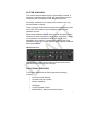
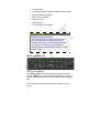
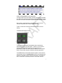
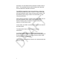
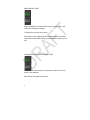
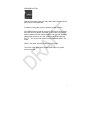
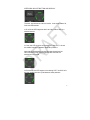
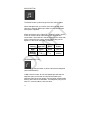
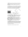
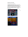
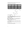
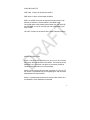
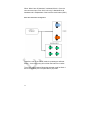
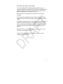
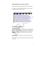
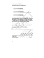
Pg
Chg
Cover………………....0
Page #…………...…...0
TOC-1………………...0
1……………………….0
2……………………….0
3……………………….0
4……………………….0
5……………………….0
6……………………….0
7……………………….0
8.………………………0
9……………………….0
10….………………….0
11…..…………………0
12…..…………………0
13…..…………………0
14…..…………………0
15……………………..0
16 …………………….0
17 …………………….0
18 …………………….0
19 …………………….0
20 ……………………..0
21 ……………………..0
22 ……………………..0
23 ……………………..0
24 ……………………. 0
Index………………….0
Inside Back Cover…..0
Outside Back Cover…0
AMX240 Audio Panel | PILOT GUIDE
TABLE OF CONTENTS
SYSTEM OVERVIEW ......................................................................1 FUNCTIONAL OVERVIEW ..............................................................1 BEZEL CONTROLS .........................................................................2 Pilot Volume Knob...................................................................................... 2 Copilot/Passenger Volume Knob ............................................................... 3 Transceiver Selection................................................................................. 3 Split Button ................................................................................................. 5 Monitor Buttons .......................................................................................... 6 Navaid Receiver Selection Button.............................................................. 6 SPeaker Button .......................................................................................... 7 Marker Beacon Button................................................................................ 8 Mute Button ................................................................................................ 8 Intercom Isolate Button and Display........................................................... 9 Music Button............................................................................................. 10 Telephone Button ..................................................................................... 10 Replay Button........................................................................................... 11 POWER ON/OFF ...........................................................................12 ADDITIONAL FUNCTIONS ............................................................14 Integration with Avidyne IFDs................................................................... 14 Intercom ................................................................................................... 15 Unswitched INputs ................................................................................... 15 Marker Beacon ......................................................................................... 16 Auxiliary Inputs ......................................................................................... 17 Music Distribution ..................................................................................... 17 Bluetooth® Pairing and usage ................................................................. 21 Front Panel Jack- “Smart Jack”................................................................ 22 BRIGHTNESS AND LIGHTING CONTROLS ................................23 ABNORMAL OPERATIONS...........................................................23 Fail Safe Operation .................................................................................. 23 PLUG AND PLAY DETAILS ...........................................................24 INDEX …………………………………………………………………...26 2
SYSTEM OVERVIEW
This manual assumes that the pilot is appropriately licensed, is
proficient in operation of the aircraft and its equipment, and is in
compliance with all Federal Aviation Regulations (FARs).
All images contained in this manual are for reference use only,
and are subject to change.
Avidyne strongly recommends that pilots use the AMX240 system
only under VFR conditions until completely familiar with its
operation and use.
Boxed areas marked as NOTE within this manual identify certain
situations or areas of operation having safety implications. While
it is important for the operator to be familiar with all of the
information in the manual, it is essential to the safe use of the
AMX240 that pilots give careful attention to the material contained
within these NOTEs.
AMX240 Audio Panel
The AMX240 is a panel-mount audio panel that meets all the
requirements for both IFR and VFR flight.
FUNCTIONAL OVERVIEW
The Avidyne AMX240 Audio Panel supports the following
functions:
•
Dual Transceiver Support;
•
6-position Intercom System;
•
Monitor Capability;
•
Split Mode;
•
Cockpit Speaker Control;
•
Marker Beacon Receiver and Audio Control;
1
•
Crew Isolation;
•
Full-duplex telephone (wired and Bluetooth®) Support;
•
Bluetooth® Music Support;
•
Music Source Selection;
•
Muting Control;
•
Audio Replay;
•
External Audio Jack Support.
COOL FEATURE
Automatic Squelch Control
The PS Engineering designed intercom squelch
control monitors each microphone input and
instantly opens when human speech is detected.
This results in no clipping of initial speech or
excessive noise. Nor is there any need for manual
squelch adjust.
BEZEL CONTROLS
PILOT VOLUME KNOB
The left knob on the bezel controls the pilot position intercom
volume. Max volume is reached at the clockwise stop. Minimum
volume is reached just prior to the full counter-clockwise detent
stop.
There is a white tick mark that indicates the current volume
setting.
2
NOTE
Full Counter Clockwise Detent is Power On/Off
Use care when adjusting the pilot position intercom
volume to avoid inadvertently reaching the full
counter-clockwise detent which powers the unit off.
COPILOT/PASSENGER VOLUME KNOB
The right side knob on the bezel is a dual concentric knob where
the outer knob controls the passenger positions intercom volume
and the inner knob controls the co-pilot position intercom volume.
Max volume is reached at the clockwise stop and minimum
volume is reached at the counter-clockwise stop.
There is a white tick mark that indicates the current volume
setting.
TRANSCEIVER SELECTION
Transceiver Selection Controls
There are two pushbuttons associated with the transmitter
selection. The two left buttons (MIC 1 & MIC 2) control which
transceiver is selected for transmit. The right column of
pushbuttons (COM 1 & COM 2) allows selection of the receiver
audio. Push the MIC button to select the desired transmitter.
The AMX240 has an automatic selector system. Audio from the
selected transceiver is automatically heard in the headsets and
speaker (if selected). When switching from MIC 1 transmitter to
MIC 2 transmitter by pressing the MIC 2 transmitter selector
3
pushbutton, the associated COM 2 pushbutton indicator will turn
green. This guarantees that the pilot will always hear the audio
from the transceiver selected for transmit.
The AMX240 “remembers” the receiver selection, so that when
switching transmitters from MIC 1 to MIC 2, if COM 2 audio was
previously selected, COM 1 audio will continue to be heard. This
eliminates the pilot having to switch Com audio back on, after
changing transmitters.
When switching from MIC 1 to MIC 2 while COM 2 audio was not
previously selected, COM 1 audio will be switched off. In
essence, switching the mic selector will not override prior
selection of COM receiver audio.
If both COM 1 and COM 2 are selected for receive, then both will
be heard equally.
The selected MIC button will flash green during com
transmission.
In normal (not split) modes, the AMX240 gives priority to the
pilot’s radio Push-To-Talk (PTT). If the co-pilot is transmitting, and
the pilot presses their PTT, the pilot’s microphone will be heard
over the selected com transmitter.
The co-pilot will also be able to transmit on the selected radio with
their PTT as well.
4
SPLIT BUTTON
Split mode allows the pilot to transmit on COM 1 while the co-pilot
transmits on COM 2.
Irrespective of the previous selections, selecting SPLIT will place
the pilot position on COM 1 and the co-pilot position on COM 2.
When SPLIT is active, the following buttons will be green:
MIC 1, COM 1, MIC 2, COM 2
When the split mode is activated, the intercom between the pilot
and co-pilot is inhibited, although the passengers can still talk
among themselves. This is indicated by the intercom segment
lights all turning off.
The SPLIT button does not light up in green when active.
The crew intercom can be reactivated if desired by pressing the
“ISOL” button as required to get the PLT to CPLT segment to light
in green.
NOTE
No Intercom Segments Lit in Split Mode
When first pressing SPLIT mode, all Intercom
segments are turned off. Pressing the ISOL button
will re-enable intercom during SPLIT mode between
the PLT and CPLT positions.
5
MONITOR BUTTONS
MON 1 and MON 2 monitors audio output from the COM 1 and
COM 2 IFD Standby channel(s).
The buttons turn green when active.
Dual radio monitor capability allows the pilot to listen to standby
frequencies with automatic muting when the active frequency is in
use.
NAVAID RECEIVER SELECTION BUTTON
These buttons select audio from desired nav radio source to be
heard in the headsets.
Each button turns green when active.
6
SPEAKER BUTTON
Selecting this button places the radio audio that is selected by the
pilot over the cockpit speaker.
The button turns green when the speaker function is active.
If the SPKR button is held for more than 1 second, the unit enters
the Public Announcement (PA) Mode. In PA mode, the pilots mic
audio is passed over the cockpit speaker, and to all the headsets
(assuming the intercom is in ALL mode) when the pilot presses
the PTT. The co-pilot can transmit over the selected radio in PA
mode.
When in PA mode, the SPKR button will flash green.
To exit PA mode, press and hold the SPKR button for greater
than one second.
7
MARKER BEACON BUTTON
:
The Marker Beacon function is always active. The MKR button
just controls the audio part of the Marker Beacon.
A quick push of the button selects Marker Beacon audio.
Pressing and holding the button for more than 1 second will mute
the Marker Beacon audio and activate a lamp test which will light
out the Outer, Middle and Inner Marker Beacon lamps. The audio
stays muted until next beacon station received.
The MKR button turns green when Marker Beacon audio is
selected.
MUTE BUTTON
Pressing the Mute button sends a signal to any external alerting
system that is connected to the AMX240 audio panel. Examples
include traffic systems, TAWS/EGPWS systems, autopilots, etc.
When pressed, the MUTE button turns green for approximately 1
second while the external mute command is sent.
This button has no effect on Marker Beacon audio or Music. It will
stop Replay playback.
8
INTERCOM ISOLATE BUTTON AND DISPLAY
The ISOL key selects the intercom mode. It has three states: All,
Crew and Pilot Isolate.
In All, all three LED segments are lit and all positions are on a
shared intercom
In Crew, the LED segment connecting PLT and CPLT is lit and
the usable intercom is between those two positions.
Note that the passengers can talk amongst themselves but
cannot hear the crew. Passengers will also not hear the
transceiver in this case.
In Pilot Isolate, the LED segment connecting CPLT and PAX is lit
and the usable intercom is just between those positions.
9
MUSIC BUTTON
The MUSIC button cycles through the music muting modes.
When selected and lit up in white, music will mute with either
Intercom or External Radio input. Mute on is the default state
when power is applied.
Music can also be put in a Mute Off - “Karaoke” mode in which
music will continue to be heard during radio and intercom
conversation. Music will be in the background in this case at all
times, except when the crew is actually transmitting out the
airplane. In this mode, the button is GREEN.
♫ Music
Intercom
Radio
Button
Mute
Muted
Muted
WHITE
Mute Off
(Karaoke)
♫
♫
GREEN
TELEPHONE BUTTON
This button is used to answer or place a call with the telephone
(wired or Bluetooth®).
In ALL intercom mode, all crew and passengers will hear the
telephone party on the other end and will be heard by the
telephone party when they speak. Com and other selected radio
audio is also heard in the headsets. The telephone party will not
hear ATC communications, and vice versa.
10
In CREW mode, only the pilot and copilot are connected to the
telephone. Passengers will not hear the telephone. The pilot and
copilot will also have transmit capability on the selected com
transceiver.
In Pilot Isolate intercom mode, when the AMX240 is in the TEL
mode, the pilot position is in the "Phone Booth." Only the pilot will
hear the telephone, and only he will be heard. He will also have
access to Com 1 or 2, and will transmit on that radio using the
PTT. All selected audio is provided to the pilot.
REPLAY BUTTON
,
This is the “say again” function that repeats previous ATC
communications.
The AMX240 stores the last 8 incoming audio messages (up to a
total maximum of 45 seconds of audio) from the radio you have
selected for transmit. The pilot and copilot hear the playback.
To play back the last recorded message, press the REPLAY
pushbutton. You can either wait for the message to finish playing
before accessing the prior message, or cancel the current
playback and step backward. To cancel the playback, press and
hold the playback button for two seconds. The next time the
button is pressed the next earlier message will be heard.
The playback will stop whenever there is more incoming selected
com audio, and the message can be replayed from the beginning
by pressing the REPLAY button. Playback can also be stopped
by pressing the MUTE button or holding the REPLAY button for
for more than 2 seconds again.
The Replay button color does not change from WHITE.
11
POWER ON/OFF
The AMX240 will automatically power on when avionics power is
applied and perform a quick self-test.
Following a successful power-on self-test, the AMX240 will
default to the last configuration prior to the previous shutdown.
To manually power the AMX240 off, twist the Pilot Volume knob
to the full counter-clockwise position until the detent is felt/heard.
To manually power the AMX240 on following a manual power off,
twist the Pilot Volume knob clockwise out of the OFF detent.
12
13
ADDITIONAL FUNCTIONS
INTEGRATION WITH AVIDYNE IFDs
The AMX240 is designed for tight integration with the Avidyne
Integrated Flight Displays (IFDs). When connected to an IFD, the
AMX240 enables Com frequency decoding and frequency
monitoring of the two transmit and four receive channels of the
IFD com radio. This means that the active Com frequency and
agency name are displayed on the IFD so you always know with
whom you will be talking when you transmit.
IFD540 Integration
R9 Integration
14
INTERCOM
The AMX240 intercom is a 6-place high-fidelity stereo or mono
intercom with automatic voice-activated (VOX) squelch for each
mic input.
As described earlier, dedicated knobs for the pilot, copilot and
passenger intercom volumes allow for full customization for
personal preferences without relying on headset volume controls.
The AMX240 includes an “Alternate Intercom Function” which
allows the passengers to converse with the crew intercom without
also hearing aircraft radio traffic, and the crew will not hear the
passengers while the aircraft radios are also active.
To activate this “Alternate Intercom Function”, press and hold the
ISOL button for two seconds while in the ALL intercom mode (all
segments green). The PLT to CPLT segment will blink to indicate
this mode is active. This function is remembered through power
cycles.
UNSWITCHED INPUTS
Unswitched inputs are presented to the pilot and co-pilot
regardless of the audio configuration or selections. If audio
comes in via one of the unswitched/unmuted lines, any
entertainment audio is instantly muted.
“Unswitched” refers to the fact the input audio is not affected by
audio panel mode/button selections.
“Unmuted” refers to input audio not being muted by radio
transmitter keying.
Unswitched #1 is always presented to the speaker, and the crew
headphones, and is available to the pilot in fail-safe (off) mode.
Unswitched #2, is always connected to the Crew’s headphones.
However, this unswitched audio is only presented to the aircraft
speaker when the SPKR push button has been selected.
15
Unswitched #3 and #4 inputs are always presented to the crew
headphones and to the aircraft speaker.
Unswitched
Input
1
2
3
4
5 (jack)
Hear in
Fail Safe
Yes
No
No
No
No
Hear in
Crew Headset
Yes
Yes
Yes
Yes
Yes
SPKR button
Select
No
Yes
No
No
No
MARKER BEACON
The Outer marker will light up the “O” lamp and present a 400 Hz
dash tone. The lamp and tone flash on/off at a rate of 2 tones
and flashes per second.
The Middle marker will light up the “M” lamp and present a 1300
Hz alternating dot and dash tone. The combination dots and
dashes will be at a rate of 95 per minute.
The Inner marker will light up the “I” lamp and present a 3000 Hz
dot tone. The lamp and tone flash on/off at a rate of 6 tones and
flashes per second.
Marker Beacon sensitivity is defaulted to LO and is only changed
via an optional external cockpit switch.
16
AUXILIARY INPUTS
ADF audio, if wired, will be heard on MON 1.
DME audio, if wired, will be heard on MON 2.
MON 1 and MON 2 will both be heard at the same time if both
buttons are selected. Note that MON 1 and MON 2 are
connected either to the standby audio output from the radio OR
the ADF/DME so you will not hear both the COM standby and
ADF or DME.
HF audio, if wired, will be heard via the wired Telephone button.
MUSIC DISTRIBUTION
Music 1 can be the rear connector (J2, pins 23, 24, 25), the front
panel jack, OR a Bluetooth® music stream. The three inputs are
paralleled, so if more than one device is connected, all will be
combined into the audio (not recommended).
Music 2 is only sourced from the rear connector (J2, pins 26, 27,
28). Music 2 is presented only to the passengers, and cannot be
presented to the crew positions.
Music 1 is presented to the pilot and co-pilot unless “Music One
All Headsets” music distribution is selected.
17
Music Overview
Note: “Rear connector” in the above diagram refers to the rear of
the audio panel, not the rear seat music connector.
Changes to the Music Distribution Function are activated by
holding Music (♫) button until the audio mode annunciation plays.
Repeat to cycle to the next mode. The two modes available are:
•
•
Standard Music Distribution
Music One All Headsets
The power-on default mode is the last mode selected prior to the
previous power down.
18
Standard Music Distribution Configuration
Music 1 is only available to the pilot and co-pilot in the “Standard”
mode. The intercom mode switch doesn’t have any affect on the
music distribution.
When the music is standard, Music 1 will always go to the pilot
and co-pilot positions, and is never heard by the passengers.
Music 2 is always heard by the passengers, and never heard by
the pilot and co-pilot.
Music 2 will never mute, including during crew radio transmission
out of the cockpit.
19
When “Music One All Headsets” is selected, Music 1 (from the
rear connector input, Pins J2 23 & 24 only) is distributed to all
headsets and is independent of the intercom mode button (ISOL).
Music One All Headsets Configuration
Therefore, even in the CREW mode, the passengers will hear
Music 1, even though they will not hear the intercom or radios.
The music muting feature follows the selected mode for Music 1
and is controlled by the front panel Music (♫) button.
20
BLUETOOTH® PAIRING AND USAGE
To pair the AMX240 with a Bluetooth® enabled device, first
ensure the AMX240 is powered on and then from the Bluetooth®
enabled device (e.g. cell phone), search for other devices and
select the AMX240 when it appears in the list.
If an access code is required, enter “0000” to connect to the
AMX240.
When paired, the AMX240 should be able to make and receive
calls with the audio directed through the audio panel and stream
music.
Once paired, playing music from the phone will be considered the
Music #1 (wired rear location) on the AMX240. Meaning if you
have an external device plugged into Music #1 and Bluetooth®
music playing at the same time then you will hear both audio
devices.
Passengers will only hear Bluetooth® music if the unit is in the
“Music One All Headsets” mode.
If phone call is received music will mute, once phone call is
complete music will return.
21
FRONT PANEL JACK- “SMART JACK”
This jack has the ability to stream music (audio in), stream
unswitched audio (audio in) or interface cell phone audio.
Music Input
Front panel music input jack is 2.5mm-able. Any standard music
device will work. This audio will be considered “Front Panel Music
Jack” and not Music #1 (hard wired).
If nothing is plugged into Music #1 (hard wired) then the “Front
Panel Music Jack” will be the primary music input for pilot &
copilot and will mute accordingly.
Wired cell phone input
If connected through a 3- or 4-conductor cable (4-conductor with
load resistor needed for iPhone/BlackBerry) then the telephone
input will function as described earlier in this manual.
Unswitched Input
This will only switch to an unswitched input when Music #1 has
audio present. If no audio is present then this jack will “smartly”
switch over to a music input.
Stream unswitched audio will be a standard 3.5mm to 2.5mm,
one to one cable. This is mainly used with portable GPS units that
have a terrain warning.
22
BRIGHTNESS AND LIGHTING CONTROLS
Text backlighting is controlled through the aircraft dimming bus.
The buttons are backlit with white LEDs which change to green
when mode is active, except as noted.
NOTE
AMX240 Appears Off
Using the manual cockpit dimming rheostat
presents a possibility of the dimmer being turned
only up a little ways during day light operation that
would appear to turn off all of the indication lights.
Checking the position of the manual cockpit
dimming control should be the first thing to check if
the AMX240 button indications appear off/broken.
ABNORMAL OPERATIONS
FAIL SAFE OPERATION
If the audio panel detects an internal problem or if it has failed or
lost power, the fail-safe feature will connect the pilot headset and
microphone directly to the COM1 transceiver. In this case, the
AMX240 is also connected to unswitched input #1 for priority
audio alerts.
When in fail-safe mode, audio will only be heard in one ear of a
stereo headset.
Manual selection of other audio panel modes will not be available
in this case.
23
PLUG AND PLAY DETAILS
The AMX240 is plug & play compatible with:
•
Garnin GMA 340;
•
PS Engineering PMA8000;
•
PS Engineering PMA8000B;
•
PS Engineering PMA8000BT;
•
PS Engineering PMA8000B/BT/MP3 for Avidyne R9;
•
PS Engineering PMA8000C;
•
PS Engineering PMA5000EX.
This means it can literally be installed in one of those trays and
no further action or wiring is required but some functions may be
missing without adding wiring or are not supported. The following
tables identify the functions that either don’t exist in the AMX240
or will need extra wiring if they are to be available when replacing
one of the legacy audio panels that are tray compatible.
This table indicates functions that may have existed in your
legacy audio panel but are not available in the AMX240. An “X”
in the block indicates the function that may exist in the legacy
audio panel but is not available in the AMX240.
Legacy Audio Panel Features Not Supported by AMX240
24
This table indicates functions where extra wiring may need to be
added to the AMX240 tray if that function is desired. An “X” in the
block indicates the optional function that may need extra wiring if
replacing a legacy audio panel with the AMX240. See the
AMX240 Installation Manual for details.
AMX240 Audio Panel Features Requiring Extra Wiring
25
INDEX
Abnormal Operations, 22
Fail Safe, 22
Automatic Squelch Control, 2
Auxillary Inputs, 16
Bezel Controls and Modes, 2
Co-pilot/Passenger Volume, 3
Intercom Isolate, 9
Marker Beacon, 8
Monitor, 6
Music, 10
Mute, 8
Nav, 6
Pilot Volume, 2
Replay, 11
Speaker, 7
Split, 5
Transceiver Selection, 3
Telephone, 10
Bluetooth Pairing and Usage, 20
Brightness and Lighting, 22
Front Panel Smart Jack, 21
Functional Overview, 1
Integration with Avidyne IFDs, 13
Intercom, 14
Low Temperature Operations, 21
Marker Beacon, 15
Music Distribution, 16
Power On/Off, 12
Plug and Play Details, 23
System Overview, 1
Unswitched/Unmuted Inputs, 14
26
Website There is a website that provides more information on this
product at http://www.avidyne.com/products/amx240/index.asp
Service Hotline A hotline has been established to service
questions or issues regarding Avidyne products. The U.S. Toll
Free number is 1-888-723-7592. International toll free numbers
are listed at http://www.avidyne.com/contact/intphones.asp
Email Customer/product support issues can be emailed as well
•
Europe – [email protected]
•
Australia & Asia – [email protected]
•
Everywhere else should email [email protected]
When calling or emailing for product-related help, please have the
following information available, if able:
□
Customer Name/Account Information
□
Aircraft tail number
□
AMX240 serial number, and software versions, if known
□
A good description of the problem or question.
WARRANTY: AVIDYNE WARRANTS THE PRODUCT MANUFACTURED BY IT AGAINST
DEFECTS IN MATERIAL AND WORKMANSHIP FOR A PERIOD OF TWENTY-FOUR (24)
MONTHS FROM DELIVERY TO THE INSTALLER. A COMPLETE COPY OF THE
WARRANTY DATA IS ACCESSIBLE VIA THIS WEB ADDRESS:
HTTP://WWW.AVIDYNE.COM/SUPPORT/WARRANTY.ASP
SOFTWARE LICENSE: AVIDYNE CORPORATION (“AVIDYNE”) IS WILLING TO LICENSE
THIS SOFTWARE, PILOT’S GUIDE, AND RELATED MATERIALS (THE “SOFTWARE”)
ONLY ON THE CONDITION THAT YOU AGREE TO THE TERMS OF THE PUBLISHED
SOFTWARE LICENSE WHICH CAN BE ACCESSED VIA THIS WEB ADDRESS:
HTTP://WWW.AVIDYNE.COM/SUPPORT/LICENSE.ASP
AVIDYNE CORPORATION
55 Old Bedford Road
Lincoln MA 01773
P 781 402 7400 | F 781 402 7599
Toll Free 800-AVIDYNE (800 284 3963)
www.avidyne.com
http://www.avidyne.com/products/AMX240/index.asp
P/N 600-00306-000 Rev 00 DRAFT G
2