1
PRO SERIES
USER MANUAL
FOR THE
PS 260
DUAL CHANNEL AUDIO INTERFACE
CONTENTS
1.0
2.0
3.0
4.0
5.0
6.0
7.0
8.0
9.0
10.0
GENERAL DESCRIPTION . . . . . . . . . . . . . . . . . . . . . .
UNPACKING . . . . . . . . . . . . . . . . . . . . . . . . . . . . . . . . .
INSTALLATION . . . . . . . . . . . . . . . . . . . . . . . . . . . . . . .
FRONT PANEL CONTROLS . . . . . . . . . . . . . . . . . . . . .
REAR PANEL CONNECTORS . . . . . . . . . . . . . . . . . . .
SUM OUTPUTS . . . . . . . . . . . . . . . . . . . . . . . . . . . . . . .
CABLING . . . . . . . . . . . . . . . . . . . . . . . . . . . . . . . . . . . .
PARTY LINE, TECHNICAL CONCEPT . . . . . . . . . . . . .
GUARANTEE . . . . . . . . . . . . . . . . . . . . . . . . . . . . . . . . .
TECHNICAL SPECIFICATIONS . . . . . . . . . . . . . . . . . .
User Manual PS 260 / Issue 1 © 1994 ASL Intercom, Utrecht, Holland.
3
3
3
4
5
5
6
7
7
7
2
User Manual PS 260 / Issue 1 © 1994 ASL Intercom, Utrecht, Holland.
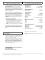
1.0
GENERAL DESCRIPTION
The PS 260 is designed to interface the ASL intercom
system (party line) to external audio equipment or 4-wire
communication systems.
The PS 260 includes two separate interfaces which are
completely identical. Each interface is power supplied via
the intercomline.
For example a fixed cabled (4-wire) intercom system can
temporarily be extended with a portable ASL set, for use
on location or a (4-wire) camera CCU can be connected to
the ASL intercom system.
The two-stage sidetone circuit (level, hi) allows you to
obtain an input/output separation better than 30 dB from
20Hz to 20KHz.
Other applications include injection of external audio
signals and monitoring of the intercom line by external
equipment e.g. recorders, paging systems, etc.
2.0
The built in testtone generator helps you to adjust or check
the sidetone level at any time.
UNPACKING
The shipping carton contains the parts listed below
* The PS 260
* User manual
If any are missing, contact your dealer.
ASL has taken great care to ensure this product reaches
you in flawless condition.
After unpacking the unit please inspect for any physical
damage to the unit, and retain the shipping carton and
relevant packing materials for use should the unit need
returning.
If any damage has occurred, please notify your dealer so
that a written claim can be initiated. Please also refer to the
guarantee section of this manual.
3.0
MECHANICAL INSTALLATION
The PS 260 will interface between ASL partyline (3-wire
intercom) and external 4-wire systems.
To connect the PS 260 with ASL partyline system, use
professional flexible microphone cable with 2 wires and 1
shield only.
Connect the partyline system cable into the intercom line
connector on the rear. To connect the PS 260 with the
external 4-wire system, connect the output of this system
with the input of the PS 260 and the input of the system
with the output of the PS 260.
There are no separate power connections to install since
the necessary DC voltages are derived from the ASL
partyline.
The PS 260 is fully protected against mis-wiring (reverse
power) or short circuit in the interconnecting cables.
User Manual PS 260 / Issue 1 © 1994 ASL Intercom, Utrecht, Holland.
3
4.0
4
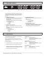
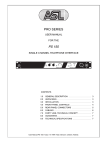
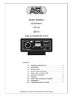
FRONT PANEL CONTROLS
The PS 260 consists of two separate interface modules in
one housing. Each module interfaces between ASL 3-wire
systems and 4-wire systems. The signal on the audio wire
of the ASL 3 wire system is converted in a balanced signal
and appears on the audio output connector.
Signals offered to the audio input are placed on the audio
wire of the 3-wire intercom line connector.
To avoid that signals on the audio input are being placed
on the audio output connector, there is a sidetone
available.
1
POWER indicator led
This led illuminates if line power is supplied by the
power supply or master station of the ASL partyline
intercom system in which the PS 260 is used.
6
2
INPUT LEVEL control knob
This knob controls the level of the input signal before it
is placed on the intercom line.
3
OUTPUT LEVEL control knob
This knob controls the level of the intercomline signal
appearing at the output connector.
4
SIDETONE LEVEL trimmer
This trimmer controls the level of the input signal
appearing at the output.
5
SIDETONE HI trimmer
This trimmer controls the input/output separation in the
high frequency range.
SIDETONE TEST knob
This hidden push button switch activates a test tone
generator which adds a 200 Hz tone to the input signal.
It allows you to adjust or check the sidetone trimmer
settings at any time. The switch can be reached with a
match or a small screwdriver.
Note: Make sure you are not disturbing any
communication because the test-tone is placed on the
intercomline which implies that all stations on that
channel can hear the test tone.
Sidetone adjustment procedure.
- Connect a monitor amplifier to the audio output.
- Turn up output level approx. half way.
- Set sidetone trimmers in start position
level : turn fully clockwise.
hi
: turn fully anti clockwise.
- Activate the testtone generator.
- Decrease test tone level by turning the level
trimmer anti clock wise and adjust for minimum
level.
- Decrease the remaining high frequencies by turning
the hi trimmer clockwise and adjust for minimum
level.
- Repeat the last two mentioned procedures, until
you are sure you have obtained the best settings
possible.
User Manual PS 260 / Issue 1 © 1994 ASL Intercom, Utrecht, Holland.
5.0
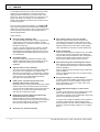
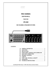
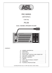
REAR PANEL CONTROLS
At the rear panel you will find the connectors for interconnecting the PS 260 with the ASL intercom system(s) and
the connectors for connecting 4-wire systems or audio
equipment.
8
9
6.0
AUDIO INPUT connector
This XLR-3 connector is for placing an audio signal on
the intercomline. It is electronically balanced in the
standard version.
An extra balancing transformer is optional (PS 260/T).
Pin assignments :
1. 0V / ground shield
2. signal +
3. signal AUDIO OUTPUT connector
This XLR-3 connector is for monitoring the intercom
line.
It is transformer balanced and capable of driving a 600
ohms load.
Pin assignments :
1. 0V / ground shield
2. signal +
3. signal -
10 INTERCOM IN connector
This XLR-3 connector is for connecting the intercom
line.
Pin assignments :
1. 0V / ground shield
2. +30V power wire
3. audio wire
11 INTERCOM LINK connector
This output is for extending the intercom line to other
user stations. It is linked to the intercom line input
connector and has the same pin assignments.
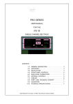
SUM OUTPUT(S)
The PS 260 offers you the possibility of monitoring both
intercomlines with one interface.
When one interface monitors two intercom lines, both
audio signals of the intercomlines will appear on the audio
output connector
Changing procedure :
a. Unscrew the upper cover plate and slide it backwards.
Connection A
function : Output of interface 1,
monitors intercom lines 1 + 2
action
: Connect the left tag of interface 1 with the
right tag of interface 2.
Connection B
function : Output of interface 2,
monitors intercom lines 1 + 2.
action
: connect the left tag of interface 2 with the
right tag of interface 1.
b. Place the unit in front of you, facing the front panel.
c. Depending on which kind of monitoring you need, the
following procedures should be followed (next column)
Connection A + B
function : Outputs of interface 1 and 2 monitor
intercom lines 1 + 2
action
: cross connect the tags.
d. Screw the cover plate back in place.
User Manual PS 260 / Issue 1 © 1994 ASL Intercom, Utrecht, Holland.
5
7.0
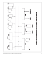
CABLING
For the PRO Series Intercom system the interconnecting
cables are of the shielded two-conductor microphone
cable type and the intercom line connectors are of the
XLR-3 type. Audio and Call signals are on XLR pin 3, DC
power is on XLR pin 2. XLR pin 1 is connected to the
shield of the cable which functions as the common return
for audio and power.
¼
Since the audio signal is transferred in an unbalanced
way, certain rules have to be obeyed when installing the
cables of an intercom network. This is to avoid earth loops
and to minimize power loss and the possible effect of
electromagnetic fields.
These rules are:
Use high quality (multipair) cable.
For interconnecting user stations, power supplies and
accessories in an ASL Intercom network, use high
quality shielded two-conductor (minimum 2x 0.30 mm2)
microphone cable only.
In case of a multi channel intercom network, use high
quality microphone 'multipair' cable only, each pair
consisting of two conductors (minimum 2x 0.15 mm2)
with separate shield. Multipair cable should also have
an overall shield.
Use flexible cables.
Use flexible single and multipair microphone cable
instead of cable with solid cores, especially when the
cable is subjected to bending during operation or
installation.
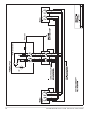
Separate cable screen to XLR pin 1.
The screen of each separate microphone cable and/or
the screen of each single pair in a multipair cable,
should be connected to pin 1 of each XLR-3 connector.
Do not connect this cable screen to the metal housing
of the connector or to metal wall boxes (outlets).
See page 12 for Earthing Concept.
Cable trunks, connection boxes and overall
multipair cable screen to clean earth.
Metal cable trunks, metal connection boxes and overall
multipair cable screen should be interconnected and,
at one point (the 'central earthing point') in the intercom
network only, be connected to a clean safety earth.
See page 12 for Earthing Concept.
Keep metal connection boxes and cable trunks
isolated from other metal parts.
Metal housings for intercom cables and connectors
should be mounted in such a way that they are isolated
from other metal cable and connector housings and
from any other metal construction parts.
¼ See Party Line, Technical Concept
6
Keep cables parallel as much as possible
When two (multi channel) units in a network are
connected by more than one cable, make sure that
these cables are parallel to each other over the whole
distance between those units. When using multipair
cable, parallelism is ensured in the best possible way.
Avoid closed loops.
Always avoid that cables are making a loop. So-called
'ring intercom' should not physically be cabled as a
ring. All cable routes should have a 'star' configuration,
with the central earthing point (usually close to the
power supply position) as the centre of the star.
Keep cables away from electromagnetic sources.
Keep intercom cables away from high energy cables,
e.g. 110/220/380V mains power or dimmer controlled
feeds for spotlights.
Intercom cables should cross high energy cables at an
angle of 90( only.
Intercom cables should never be in the same trunking
as energy cables.
Place power supplies in a central position.
In order to avoid unacceptable power losses, place the
power supplies as close as possible to where most
power consumption occurs or, in other words, most
user stations are placed.
Connect ASL power supply to a 'clean' mains
outlet.
The ASL power supply may be connected to the mains
power outlet to which other audio equipment is
connected. Avoid using mains outlets which also power
dimmer controlled lighting systems.
In case of more complex installations, don't hesitate to
contact us. Please send us a block diagram of the
planned network with a list of all user stations and their
positions, and we are happy to advise you on cabling
lay-out.
User Manual PS 260 / Issue 1 © 1994 ASL Intercom, Utrecht, Holland.
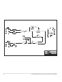
8.0
PARTY LINE, TECHNICAL CONCEPT
ASL's PRO Series offers a complete two way ('full duplex')
communications system.
Users of the system are connected via a 'party line'.
Master stations (with built-in power supply), beltpacks,
speaker stations and power supplies are interconnected
via standard microphone cable. One wire is used as an
audio line, one as a power line and the screen of the cable
functions as earth/return.
Current drive is used for signal transfer. Each station
utilises a current amplifier to amplify the microphone signal
and place it on the common audio line where, due to the
constant line impedance (situated in the power supply
between XLR pin 3 and 1), a signal voltage is developed
which can be further amplified and sent to headphones or
loudspeakers.
This principle has three advantages:
- the use of a single audio line allows several stations to
talk and listen simultaneously.
- due to the high bridging impedance offered by each
station, the number of stations 'on line' has no
influence on the level of the communications signal.
- power and audio to the intercom stations use the same
cable.
The Call signal is also sent as a current on the audio line.
It develops a DC potential over the line impedance which
will be sensed by each station and interpreted as a Call
signal.
10.0 TECHNICAL SPECIFICATIONS PS 260
INPUT AMPLIFIER
input impedance
input level
frequency response
min. 10Kohm
+30 to - 10 dBm
60Hz - 20KHz (-3dB)
INTERCOM LINE DRIVER
Max. output current
output impedance
3mA rms
> 150 Kohm
OUTPUT AMPLIFIER
output impedance
maximum load
max. output level
frequency response
SIDETONE
rejection
< 25 ohms
600 ohms
+20 to -20 dBm
40 Hz - 20 Khz
min. 30 dB (20Hz - 20 Khz)
DIMENSIONS AND WEIGHT
width
height
depth
weight
GENERAL SPECIFICATIONS
supply voltage
supply current
audio line level
signal-to-noise
station bridging impedance
19" (483mm)
1U (44.5mm)
126mm
1565 grams
+30VDC (12V to 32V)
33 mA quiescent / each
-18dBm (max. 0dBm)
80dB
> 150 Kohm
Note: 0 dBu = 775 mV into open circuit.
9.0 GUARANTEE
ASL reserve the right to alter specifications without further
notice.
This unit is warranted by ASL Intercom to the original enduser purchaser against defects in workmanship and
materials in it's manufacture for a period of one year from
the date of shipment to the end-user.
Faults arising from misuse, unauthorised modifications or
accidents are not covered by this warranty. If the unit is
faulty, it should be sent in it's original packing to the
supplier or your local ASL dealer, with shipping prepaid. A
note must be included stating the faults found and a copy
of the original suppliers invoice.
THIS PRODUCT WAS DESIGNED, DEVELOPED AND
MANUFACTURED BY :
AMPCO SOUND LAB BV
MAARSSEN (UTRECHT) HOLLAND
User Manual PS 260 / Issue 1 © 1994 ASL Intercom, Utrecht, Holland.
7
8
User Manual PS 260 / Issue 1 © 1994 ASL Intercom, Utrecht, Holland.
User Manual PS 260 / Issue 1 © 1994 ASL Intercom, Utrecht, Holland.
9
10
User Manual PS 260 / Issue 1 © 1994 ASL Intercom, Utrecht, Holland.
User Manual PS 260 / Issue 1 © 1994 ASL Intercom, Utrecht, Holland.
11