1
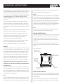
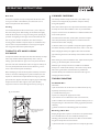
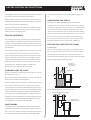
®
charnwood
Operating & Installation Instructions
CONTENTS
O P E R AT I N G I N S T R U C T I O N S
Fuels
3
Door Operation
3
Multifuel Grate
3
Lighting
4
Controlling The Fire
4
Riddling
4
Refuelling
4
Ash Clearance
4
Special Points when burning Coal
5
Special Points when burning Wood & Peat 5
Overnight Burning
5
Maintenance
5
Throat Plate & Flueway Clearing
6
Chimney Sweeping
6
Trouble Shooting
6
If You Need Further Help
8
INSTALLATION INSTRUCTIONS
Health & Safety Precautions
9
Specification
9
Chimney
9
Hearth & Fire Surround
9
Central Heating System
10
System Controls
11
Connection to Flues
11
Soot Doors
11
Unpacking The Stove
11
Fitting The Stove To Its Stand
11
Pre Lighting Check
12
Commissioning
12
Dimensions
13
Parts Lists
14
Certification
15
Ref. Cove 2B v2 06.13
charnwood
OPERATING INSTRUCTIONS
®
Before lighting the stove check with the installer that the work and
When burning coal a little extra care is needed. Please take note of
checks described in the Installation Instructions have been carried out
the section "Special Points For Burning Coal".
correctly and that the chimney has been swept, is sound and free
Wood
from any obstructions. Do not light the stove before the boiler has
Only dry well seasoned wood logs should be burnt on this appliance
been filled with water - this can damage the boiler and will
as burning wet unseasoned wood will give rise to heavy tar deposits
invalidate the guarantee. The stove is not suitable for use in a shared
in the stove, on the glass and within the chimney. For the same reason
flue system.
hard wood is better than soft wood. Burning wet unseasoned wood
Your Cove stove has been designed to work with the minimum
will also result in considerably reduced outputs. The wood logs
effort. If any operation - such as riddling the grate or opening and
should be cut and split and then left to season in a well ventilated dry
closing the door - begins to require extra force then the cause must
place for at least one year but preferably two years before use.
be investigated and corrected to prevent damage being caused to the
Peat
stove.
Ensure that the peat is well dried before use. Burning wet peat will
Remember that the stove will be hot and is made from hard material.
give rise to heavy tar deposits and reduced outputs.
Ensure that you have good balance before operating the fire.
When using the stove in situations where children, aged and/or
DOOR OPERATION
infirm persons are present a fireguard must be used to prevent
The door handle has been carefully designed to be removed from the
accidental contact with the stove. The fireguard should be
stove during normal operation and re-fitted prior to loading and de-
manufactured in accordance with BS 8423:2002.
ashing. However, if you need to open the door when the fire is
running at maximum then the additional use of a cloth or glove may
Do not use an aerosol spray on or near the stove when it is alight.
be required.
There is a risk of explosion or flash ignition of the spray.
Take care not to touch the door as it will be hot when the fire is
This stove is capable of intermittent or continuous operation.
burning. Turn the door handle anti-clockwise to open, and clockwise
FUELS
to close.
Please pay careful attention to the special points made with each type
Fig. 1. Stove Controls
of fuel as they will help you to get the best from your stove. It must
Identification Plate,
Lift Plate to View
be remembered that only smokeless fuels may be burnt in smoke
control areas on this stove. If you are not sure whether you are in a
smoke control area, then please check with your Local Authority.
Door Opening Tool,
Anti-Clockwise to Open
At first you may find it helpful to try several fuels to find the most
suitable. If you are unable to obtain the fuel you want ask your
Thermostatic
Air Control
Clockwise to
Increase
supplier, or an approved fuel distributor to suggest an alternative.
PETROLEUM COKE IS NOT SUITABLE FOR USE ON THIS
APPLIANCE. ITS USE WILL INVALIDATE THE GUARANTEE.
Smokeless Fuels
Only authorised smokeless fuels may be burned in smoke control
Airwash Control,
Pull to Open
areas on this appliance. Your local fuel supplier or stove shop will be
Grate Lever
able to advise you which fuels are available locally. Take care to only
burn good quality fuels in order to obtain the greatest efficiency and
MULTIFUEL GRATE
to maintain the life of the appliance.
Your Charnwood stove is fitted with a multifuel grate which enables
both solid fuels and wood to be burned equally effectively. The grate
Coal
has two positions:
Housecoal doubles, trebles or cobbles may all be burnt. Do not use
1) In the solid fuel position the grate bars are vertical with gaps in
singles, small nuts, or coal dust. It is important that large size coal is
between allowing the primary combustion air to come up through
used (ie. larger than 2 inch or 50 mm in size). The coal should be dry.
3
charnwood
OPERATING INSTRUCTIONS
®
the grate and through the fuel bed.
CONTROLLING THE FIRE
2) In the wood position the grate bars are horizontal, allowing the
The rate of burning and hence the output is regulated by the control
combustion air to come round the sides of the grate and over the top
knob on the side of the fire and the airwash control (see Fig.1).
of it. When in the wood position ash is able to build up on the grate
The control knob is linked to a thermostat which senses the boiler
as is necessary for effective wood or peat burning.
temperature. The number at the front of the knob is the number at
Movement of the grate from one position to the other is effected
which it is set. Turn the knob clockwise to increase the water
using the tool supplied as shown in Fig.2. The grate is put into the
temperature or anti-clockwise to decrease.
solid fuel position by moving the tool up until the handle is in the 1
The airwash control should be kept at least slightly open most of the
o'clock position. The grate is put into the wood position by moving
time to keep the glass clean. It may be fully opened when rapid
the tool down until the handle is in the 5 o'clock position. To riddle
heating is required or to help clean any deposits from the glass. It will
the appliance when burning solid fuels the tool should be moved
not be possible to keep the glass clean if this control is fully closed,
between the 1 o'clock and 3 o'clock positions several times. When
particularly immediately after refuelling.
burning wood or peat the ash should be allowed to build up and
For correct firing we recommend the use of a stove pipe
riddling should only be carried out once or twice a week.
thermometer which may be purchased from your supplier or from
LIGHTING
ourselves.
The stove may be lit using dry kindling wood and paper or fire
RIDDLING
lighters. Set the grate into either the closed position or the open
When burning wood, ash should be allowed to build up and only
Fig. 2. Multifuel Grate
riddled when the ash begins to cover the slots in the rear fireplate.
The fire should be riddled with the door shut (see Fig. 2). Place the
ion
sit
Po
el
u
dF
tool onto the riddling lever and rotate between the 1 o'clock and 3
o'clock positions several times. Too much riddling can result in
li
So
emptying unburnt fuel into the ashpan and should therefore be
Riddle
avoided. After riddling, the grate should be put back into the
position as required (the tool should be in the 1 o'clock position for
d
oo
W
open grate or in the 5 o'clock position for closed grate).
s
Po
REFUELLING
n
itio
Door Opening Tool rotated 180°
and pushed fully on to Riddler Knob
Keep the firebox well filled but do not overfill to prevent fuel from
position as required. Place the paper, or fire lighters, and kindling on
spilling over the top of the front fire bar. Logs should be evenly
the grate and cover with a few small dry logs. Open the air controls
distributed filling across the fire bed to give the most pleasing flame
fully (see Fig. 1). Light the paper or fire lighters. Close the door until
pattern.
the fuel is well ignited then load with fuel. Once the fire is up to
Care should be taken especially when burning wood that fuel does
temperature the airwash system will begin to work, so allow the fire
not project over the front fire bar or damage to the glass may be
to become hot before adjusting the air controls to the required
caused when the door is closed. It can also cause the glass to black
setting.
up. Maximum filling height is such that logs cannot fall from the fire
On initial lighting, the stove may smoke and give off an odour as the
when the doors are opened. Liquid fuels are not to be used on this
silicon paint with which the firebox is painted reacts to the heat. This
stove.
is normal and will cease after a short time, but meanwhile the room
ASH CLEARANCE
should be kept well ventilated.
The ashpan should be emptied regularly before it becomes too full.
At first only light a small fire and burn it slowly for two hours to allow
Never allow the ash to accumulate in the ashpan so that it comes in
any residual moisture in the bricks to evaporate.
contact with the underside of the grate as this will seriously damage
When relighting the stove, riddle slightly, and then empty the ashpan.
the grate bars. The ashpan is handled using the Door Opening tool
provided. Ensure that the tongue of the ashpan is protruding through
4
charnwood
OPERATING INSTRUCTIONS
®
Fig. 3. Ashpan Removal
OVERNIGHT BURNING
For overnight burning the fire doors must be closed. Use large logs
rather than small ones.
If the fire is very low then it may be necessary to add a little fuel and
turn the thermostat control up to maximum for a brief period until
the fire is burning brightly before filling with fuel. When the new fuel
has ignited, the thermostat control should be turned down to the
1
required setting. If the central heating pump is off overnight then the
2
thermostat may be left at the same setting for both day and night
Tongue must be visible to
ensure correct tool location.
operation. If the central heating pump is on overnight then set the
thermostat control to give the required level of heating. Some
the slot in the top of the tool before lifting (See Fig.3). Care should
experimentation will be necessary to find the settings most suitable
be taken to ensure that ash is cool before emptying it into plastic
for the particular fuel used and the draw on the chimney.
liners or bins.
To revive the fire, add some small logs and open the thermostat
To make ash removal easier there is a special Charnwood ash carrier
control to maximum. When the fire is burning well load on more fuel
available. This may be purchased from your supplier or, in case of
as necessary and move the thermostat control to the desired setting.
difficulty, from Charnwood.
MAINTENANCE
SPECIAL POINTS WHEN BURNING COAL
Cleaning
When loading the stove take care not to smother the fire, instead fill
The stove is finished with a high temperature paint which will
the firebox in two stages waiting between each stage for the flames
withstand the temperatures encountered in normal use. This may be
to appear above the fire.
cleaned with a damp lint-free cloth when the stove is cold. Should repainting become necessary then special high temperature paints are
After a period of slumbering always turn the air control up to
available from your supplier or from Charnwood.
maximum and wait until flames appear above the fuel bed before
opening the doors.
Cleaning the Glass
Burning coal will produce more soot deposits than other fuels,
The glass in the door is a special ceramic glass which is able to
especially if the fire is run at low levels for long periods. It is therefore
withstand high temperatures. Before cleaning the glass open the door
vital to clean the throat plate regularly, weekly cleaning is
and allow it to cool. Clean the glass using a damp cloth and then wipe
recommended. Please also note that some blackening of the glass
over with a dry cloth. Any stubborn deposits on the glass may be
may occur when burning coal.
removed with a proprietary stove glass cleaner or ceramic hob
cleaner. Some deposits on the glass may be burnt off simply by
Never fully close the Airwash control when burning coal.
running the fire at a fast rate for a few minutes. Do not use abrasive
cleaners or pads as these can scratch the surface which will weaken
SPECIAL POINTS WHEN BURNING
WOOD AND PEAT
the glass and cause premature failure. Aerosol spray cleaners should
not be used near the appliance whilst it is under fire.
The grate should be kept in the wood burning position and should
not be riddled until the ash becomes so deep that it begins to block
When Not in Use
the passage of air into the firebox at the side of the grate. When this
If the fire is going to be out of use for a long period (for instance in
is the case do not remove all of the ash using the riddling mechanism
the summer) then to prevent condensation, and hence corrosion, the
but keep a layer about half an inch thick as this enables the wood to
air control should be left fully open and the fire door left ajar. It is
burn more effectively. When burning wood or peat use the airwash
also advisable to sweep the chimney and clean out the fire. Spraying
control in the same way as described (see "CONTROLLING THE
the inside of the door and firebox with a light oil, such as WD40, will
FIRE") When lighting the fire a few small dry logs with a good
also help to keep all internal parts working well.
amount of kindling will help to get the fire up to temperature quickly.
After long periods where the fire has been out of use, the chimney
and appliance flueways should be cleaned before lighting.
5
charnwood
OPERATING INSTRUCTIONS
®
Door Seals
CHIMNEY SWEEPING
For the fire to operate correctly it is important that the door seals
The chimney should be swept at least twice a year. Where a top
are in good condition. Check that they do not become worn or
outlet is used it will generally be possible to sweep the chimney
frayed and replace them when necessary.
through the appliance.
Servicing
If the stove is fitted in place of an open fire then the chimney should
It is recommended that the fire is serviced once a year to keep it in
be swept one month after installation to clear any soot falls which
first class working order. After cleaning out the firebox thoroughly,
may have occurred due to the difference in combustion between the
check that all internal parts are in good working order, replacing any
stove and the open fire.
parts that are beginning to show signs of wear. Check that the door
First remove the front firebar, side fire plates, and the throat plate.
seals are in good condition and that the door seals correctly. A
Then sweep the chimney ensuring that soot is removed from all
servicing guide is available on request. Repairs or modifications may
horizontal surfaces after sweeping.
only be carried out by the Manufacturer or their approved agents.
In situations where it is not possible to sweep through the appliance
Use only genuine Charnwood replacement parts.
the installer will have provided alternative means, such as a soot door.
THROAT PLATE AND FLUEWAY
CLEANING
After sweeping the chimney the appliance flue outlet and the flue
pipe connecting the stove to the chimney must be cleaned with a flue
It is important that the throat plate and all the stove flueways are kept
brush.
clean. They should be checked approximately once a week, by
After clearing any soot from within the stove, replace the throat plate
looking up into the firebox for signs of soot or fly-ash on the throat
(see Fig. 4), the side fireplates, and front firebar.
plate and at the sides of the firebox. If there are signs of a build up of
Different types of sweep’s brushes are available to suit different
soot or fly-ash deposits then the fire must be allowed to go out in
flueways. For standard brick chimneys a wire centre sweep’s brush
order to clean the throat plate and flueways.
fitted with a guide wheel is recommended. For prefabricated
Before attempting to clean the throat plate and flueways ensure that
insulated chimneys the manufacturers instructions with regard to
the fire is cold. Wear suitable gloves to prevent irritation from soot
sweeping should be consulted.
deposits. To remove the throat plate lift the front edge up, pull the
TROUBLE SHOOTING
plate forwards to align the slots with the support pegs and then hinge
the plate down from its back supports. Lift up from the back
Fire Will Not Burn
supports and rotate to remove through the doorway (see Fig. 4).
Check that:
a) the air inlet at the rear of the stove is not obstructed in any way,
b) chimneys and flueways are clear,
Fig. 4. Throat Plate
c) a suitable fuel is being used,
d) there is an adequate air supply into the room,
e) an extractor fan is not fitted in the same room as the stove,
f) there is sufficient draw in the chimney (once the chimney is warm a
draught reading of at least 0.10 inches water gauge (25Pa) should be
obtained),
g) all flue connections and the blanking plate are well sealed.
1
2
Lift throat plate at front,
then pull forward and
swing down.
Blackening of Door Glass
Keeping the glass clean requires a certain amount of experimentation
due to the differences in the draw of different chimneys. The
3
following points should be noted and with a little care should enable
the glass to be kept clean in most situations:
a) The airwash relies on a supply of heated air to keep the glass clean,
6
charnwood
OPERATING INSTRUCTIONS
®
therefore, when lighting the stove allow the fire bed to become well
Fire blazing out of control
established before closing the air control. This also applies when re-
Check that:
fuelling the stove.
a) The door is tightly closed.
b) When re-fuelling keep the fuel as far back from the front firebar
b) The air controls are set at the minimum setting.
as possible, do not try to fit too much fuel into the firebox.
c) A suitable fuel is being used.
d) The thermostat flap is closed against the Thermostat Box, see
c) Wet wood or logs overhanging the front firebars will cause the
Fig.5.
glass to blacken.
e) Door seals and air control flap pads are intact.
It is always more difficult to keep the glass clean when running the
Over-Firing
stove very slowly for long periods.
If the fire is over-fired it will cause premature failure of the internal
Check that all flue connections and the blanking plate are well
fire parts. Overfiring is occurring when any parts of the fire begin to
sealed. It is also important that the chimney draw is sufficient (when
glow red. To prevent over-firing ensure that:
the chimney is warm a draught reading of at least 0.10 inches water
a) the door seals are kept in good condition, and that the doors are
gauge (25 Pascals) should be obtained), and that it is not affected by
sealing correctly,
down-draught.
b) the thermostat on the fire is working correctly,
c) a suitable fuel is being used,
Fig. 5. Thermostat - view with cover removed
d) the fire is not fitted onto a heating system which is too large.
Control
Knob
Freezing
Do not light the fire if there is any possibility that any parts of the
system may be frozen.
Lack of Heat To Radiators / Hot Water
Check that:
Thermostat
Arm
a) the fire is burning properly - if not then carry out the checks under
"Fire Will Not Burn".
Thermostat
Flap
Thermostat
Box
b) the throat plate is fitted correctly (see Fig. 4.) and that it is not
distorted.
Fume Emission
c) the door seals are in good condition.
Warning Note: Properly installed and operated this appliance will
d) If the hot water goes cold when the pump is turned on, or if some
not emit fumes. Occasional fume from de-ashing and re-fuelling
radiators are hotter than others, then the system may need balancing,
may occur. Persistent fume emission is potentially dangerous and
the pump may be pumping the water too quickly around the system,
must not be tolerated. If fume emission does persist, then the
or the radiators may need bleeding. Please ask your installer to check
following immediate actions should be taken:
these points.
a) Open doors and windows to ventilate the room.
Chimney Fires
b) Let the fire out and safely dispose of the fuel from the
If the chimney is thoroughly and regularly swept, chimney fires should
appliance.
not occur. However, if a chimney fire does occur, push the air control
c) Check for flue or chimney blockage, and clean if required.
in fully and tightly close the door of the appliance. This should cause
d) Do not attempt to re-light the fire until cause of fume has been
the chimney fire to go out in which case the control should be kept
identified, if necessary seek professional advice.
closed until the stove has gone out. The chimney and flueways should
The most common cause of fume emission is flueway or chimney
then be cleaned. If the chimney fire does not go out when the above
blockage. For your own safety these must be kept clean.
action is taken then the fire brigade should be called immediately.
After a chimney fire the chimney should be carefully examined for
7
charnwood
OPERATING INSTRUCTIONS
®
any damage. Expert advice should be sought if necessary.
IF YOU NEED FURTHER HELP
If you need further help with your Charnwood Cove then your
Installer will be able to provide the answers to most questions.
Your Local Charnwood Premier Dealer has a great deal of
experience and will also be able to provide helpful advice. Further
help is available from the Charnwood Customer Services
department who will be pleased to give advice, if necessary.
8
charnwood
INSTALLATION INSTRUCTIONS
®
HEALTH & SAFET Y PRECAUTIONS
CHIMNEY
Please take care when installing the stove that the requirements of
In order for the appliance to perform satisfactorily the chimney height
the Health and Safety at Work Act 1974 are met.
must not be less than 4 metres measured vertically from the outlet of
Some types of fire cement are caustic and should not be allowed to
the stove to the top of the chimney. The minimum internal chimney
come into contact with the skin. In case of contact wash with plenty
size is 150mm diameter (6 inches) or 150mm x 150mm.
of water.
This stove is NOT to be used in a shared flue. If an existing chimney is
If there is a possibility of disturbing any asbestos in the course of
to be used it must be swept and checked, it must be in good
installation then please use appropriate protective equipment.
condition, free from cracks and blockages, and should not have an
excessive cross sectional area. If you find that the chimney is in poor
There must not be an extractor fan fitted in the same room as the
condition then expert advice should be sought regarding the necessity
stove as this can cause the appliance to emit fumes into the room.
of having the chimney lined. If it is found necessary to line the
There must be an adequate air supply into the room in which the
chimney then a lining suitable for Solid Fuel must be used.
appliance is installed to provide combustion air. The combustion air
If there is no existing chimney then a prefabricated block chimney or
supply must be via a permanently open vent. The minimum free area
2
a twin walled insulated stainless steel flue to with BS EN 15287-1:
2
is 62.7cm (9.7 in ).This is particularly necessary if the room is double
2007 can be used either internally or externally. These chimneys
glazed. It must be positioned such that it is not liable to blockage.
must be fitted in accordance with the manufacturers instructions and
In addition to these instructions the requirements of BS.8303 and
Building Regulations.
BS EN 15287-1:2007 must be fulfilled. Local Authority Bylaws and
Anki pumice liners or chimney blocks will give a highly insulated
Building Regulations regarding the installation of Solid Fuel burning
chimney which will work well with all fuels. For details ring Anki
appliances, flues and chimneys must also be observed, including those
Chimney Systems on (01983) 527997.
referring to national and European Standards.
Single wall flue pipe is suitable for connecting the stove to the
SPECIFICATION
chimney but is not suitable for using for the complete chimney.
Specification
Wood
Anthracite
If it is found that there is excessive draw in the chimney then a
Nominal Heat Output (kw)
11 (37,533 Btu/h)
16.4 (55,960 Btu/h)
draught stabiliser should be fitted.
Space Heating Output (kw)
4.6 (15,696 Btu/h)
7.1 (24,226 Btu/h)
Water Heating Output (kw)
6.4 (21,828 Btu/h)
9.3 (31,733 Btu/h)
Normal Flue Gas Temp (°C)
315
353
Flue Gass Mass Flow g/s
8.6
11.6
Max Water Pressure Bar (ft. H2O)
1.5 (50)
It is important that there is sufficient draw in the chimney and that
the chimney does not suffer from down-draught. When the chimney
is warm the draw should be not less than 0.1 inches water gauge. If in
doubt about the chimney seek expert advice.
Min Distance From Combustibles and also for access:
HEARTH AND FIRE SURROUND
Sides (mm)
100
The stove must stand on a fireproof hearth and must be situated at
Back (mm)
100
least the following distances from any combustible material:
Max Hearth Temp (°C)
53
Min Flue Draught Pa (in water)
25 (0.1)
Boiler Capacity Litres
8.4
Side
100mm (4in)
Back
100mm (4in)
The hearth must be at least 12mm (0.5inches) thick. The positioning
Weight (kg)
Low Stand
127
of the stove and the size of the hearth are governed by building
Store Stand
133
regulations for Class 1 appliances. These building regulations state
Centre Stand
146
that the hearth must extend in front of the stove by at least 300mm
(12 inches) and to the sides of the stove by at least 150mm (6
The outputs were obtained burning:
inches). When the fire door is open, it extends beyond the front of
1) Seasoned hardwood over a 1.5 hourly refuelling cycle.
2) Welsh Anthracite over a 4 hourly re-fuelling cycle.
the stove by 414mm (16.3in).
If in doubt as to the positioning of the stove expert advice should be
9
charnwood
INSTALLATION INSTRUCTIONS
®
Fig. 6. Typical Central Heating & Hot Water System
Using 4 Boiler Tappings
sought either from the supplier or the local building inspector.
The fireplace must allow good circulation of air around the appliance
to ensure that maximum heat is transferred to the room and also to
22mm Open Vents
Feed and
Expansion
Tank
Overflow
prevent the fireplace from overheating. A gap of 150mm (6 inches)
each side and 300mm (12 inches) above the appliance should give
sufficient air circulation. If a wooden mantelpiece or beam is used in
Cold Water Tank
Overflow
the fireplace it should be a minimum of 460mm (18 inches), and
Domestic Hot Water
Draw Off
preferably 600mm (24 inches) from the appliance. In some situations
Gravity
Radiator
In order for the fire to operate correctly there must be an air gap
behind the appliance of at least 40mm, but be aware that this
distance will need to be greater in some cases to meet Building
Regulation requirements.
Gravity Return 28mm
Gravity Flow 28mm
it may be necessary to shield the beam or mantelpiece to protect it.
Drain Cock
Indirect Hot Water Cylinder
Central Heating Flow
Circulating Pump
CENTRAL HEATING SYSTEM
Minimum Return
Thermostat
The central heating system must comply with BS EN 14336, BS EN
Central Heating Return
Drain Cock at Lowest Point
12828 and BS EN 12831.
The installation of any electrical services during the installation of this
boiler and the associated heating system must be carried out by a
Fig. 7. Typical Central Heating & Hot Water System
Using 3 Tappings
registered competent electrician and in accordance with the
requirements of the latest issue of BS 7671.
22mm Open Vents
Feed and Expansion Tank
Cold Water Tank
If the system is to be a combined heating and domestic hot water
system then a double feed indirect hot water storage cylinder to
Overflow
Overflow
BS:1556 part 1 should be used. In order to prevent the build up of
scale and corrosion a suitable inhibitor should be used. The system
Domestic Hot
Water Draw Off
must be correctly vented as shown in Figs. 6 and 7. The height
Gravity Radiator
exceed 15.2 metres (50 feet).
If all four boiler tappings are used then, if possible, diagonal pairs
should be connected for domestic hot water and central heating.
Minimum Return Thermostat
Where a common return is used an injector tee must be
Circulating Pump
incorporated into the system as shown in Fig.8. This will ensure that a
Central
Heating Return
Gravity Return 28mm
Gravity Flow 28mm
differential between the header tank and the appliance must not
Drain Cock
Indirect Hot Water Cylinder
Central
Heating Flow
good domestic hot water supply is maintained when the central
heating pump is operating.
Drain Cock at Lowest Point
Injector Tee
The system must incorporate a gravity circuit which will normally
heat the domestic hot water and an unvalved radiator with an output
of at least 1 kW. When the appliance is not connected to a domestic
Fig. 8. Injector Tee
hot water system the unvalved radiator(s) on the gravity circuit must
have an output of at least 1.25 kW. This is to prevent boiling in case
Gravity Return (28mm Pipe)
of pump failure. All pipework in the primary circuit must be 28 mm
diameter and the gravity flow pipe must rise continuously from the
Central Heating
Return
boiler to the open vent. Two typical systems are shown in Figures 6
and 7.
10
Common
Return to Boiler
(28mm Pipe)
charnwood
INSTALLATION INSTRUCTIONS
®
If the appliance is used to heat a small central heating system then the
Various types and positions of soot doors are shown in figures 9 to
heat output to the room from the fire will be reduced.
12.
Fitting a radiator in the same room as the fire is recommended as it
UNPACKING THE STOVE
will allow greater flexibility in the way that the system is operated as
The stove arrives bolted and shrink-wrapped to its pallet. The
well as ensuring that there is sufficient heat.
wrapping is first removed, then the stove released from the pallet by
Connect the heating system to the boiler ensuring that the primary
removing the 4 pallet bolts using a 10mm spanner. The pallet brackets
flow pipe rises continuously from the appliance to the vent. Fill the
can now be removed from the stove by tilting it and using a 13mm
system with water and check for leaks.
spanner to remove the bolts. These 4 bolts are required for levelling
on the Low Stand or fixing on the Centre Stand, but are not used on
SYSTEM CONTROLS
the Store Stand. The Stove comes with the Low Stand fitted and if
this is to be used, the Stove may now be moved to its final position.
The circulating pump may be controlled by means of time switches,
The pallet is intended to be cut up and used for kindling fuel.
room thermostats or outdoor thermostats. Radiators may be either
manually or thermostatically controlled. These controls will all work
FITTING THE STOVE TO ITS STAND
in conjunction with the thermostat on the appliance and the low limit
1. Centre stand
pipe thermostat.
The Stand is first positioned on the hearth in the desired position of
We recommend fitting a pipe thermostat onto the gravity return to
the stove. The lower cover must be removed from the stove by first
act as a low limit thermostat This should be wired into the mains
unscrewing the air control knob, then removing the 6mm bolt on
supply to the pump so that if the gravity return temperature drops
each side using a 4mm allen key. The Cover may now slide off. Ensure
below 45°C then the pump will cut out. This will help to prevent
Fig.9. Vertical register plate with bricked up fireplace
condensation forming on the boiler faces and will thereby increase
the life of the boiler. It will also ensure that priority is given to the
Soot Door
in side or rear
of Chimney
domestic hot water. These thermostats are available from
Charnwood if you are unable to obtain them locally.
CONNECTIONS TO FLUES
Register Plate
There are several ways of connecting the stove to the flue. These are
illustrated in figures 9 to 12.
If the vertical rear flue connector (shown in Fig. 12) is used then the
chimney may be swept through the appliance.
Horizontal lengths of flue must be kept to a minimum and should not
be more than 150mm (6 inches) long. The sealing face of the flue
collar should be coated with fire cement before fixing to the body of
Fig. 10. Horizontal register plate with rear flue connection
the stove using the two screws provided. The blanking plate must be
removed, sealed with fire cement and refitted, care being taken to
Alternative Soot Door Positions
ensure that the fold on the clamping plate is in line with the lugs on
the firebox as shown on the label on the clamping plate. Ensure that
the clamping plate does not prevent the throat plate from seating
Register Plate
With Soot Door
correctly. All flue connections must be well sealed.
SOOT DOORS
It is possible to pass a 16 inch diameter sweeps brush through the
appliance but in most back outlet installations it will be necessary to
have a soot door to enable the chimney to be swept. This may either
be in the actual brickwork of the chimney or in the register plate.
11
charnwood
INSTALLATION INSTRUCTIONS
®
Fig. 11. Horizontal register plate with top flue connection
Alternative
Soot Door
Positions
Fig. 13
1
4
3
Register Plate
With Soot Door
4
2
2
2
were used to secure the cover and replace the Air Control Knob.
Fig. 12. Horizontal register plate with optional vertical rear flue connector
PRE LIGHTING CHECK
Alternative
Soot Door
Positions
Before initial lighting the following points should be checked:
1. The bottom grate bars must all be fitted and should move freely
and easily when the riddling mechanism is operated.
2. The plates round the sides and back of the grate must be in
Register Plate
With Soot Door
position and sitting correctly.
3. The throat plate must be fitted in the roof of the appliance and
should be checked to ensure that it has not become dislodged in
transit. The method of location and positioning of the throat plate is
shown in Fig. 4.
4. The heating system must be correctly connected and filled with
water before lighting the fire. Lighting the fire without water in
the boiler can cause serious damage to the boiler and will
that the pallet brackets have been removed from the stove, then lift
invalidate the guarantee.
the stove on to the stand, aligning the 4 tapped holes in the base
brackets with the 4 slots in the top of the stand. NOTE: This requires
COMMISSIONING
at least 2 people. The stove is fixed to its stand using 4 M8 x 20mm
On completion of the installation and after allowing a suitable period
bolts and 4 plain washers. A 13mm open ended spanner is required.
of time for the fire cement and mortar to dry out, the stove should
Replace the cover, side bolts and Air Control Knob.
be lit and checked to ensure that smoke and fumes are taken from
the appliance up the chimney and emitted safely. Also check all joints
2. Store stand
and seals. On completion of the installation and commissioning please
Place the Store Stand on the hearth, with at least 100mm clear space
leave the operating instructions with the customer and advise them
behind it. Remove the lower cover as described above - it is not used.
on the use of the appliance.
With 2 people, carefully lift the stove on to the stand such that the
front end of the Air Control Rod is lowered down inside the stand.
Take care not to bend or damage the Air Control Rod. Temporarily
rest the stove on the stand in this position and pull the Air Control
Rod through the hole in the front of the stand. Now move the stove
towards you to align the slots in the side of the stand with the 6mm
tapped holes in the base brackets. Fix in position with the bolts that
12
charnwood
DIMENSIONS
®
145
Flue outlet to suit 150mm(6” f lue pipe)
88
153
456
399
Top View
Optional Vertical Rear Flue Adapter
80
STORE STAND
554
394
153
999
944
872
824
587
350
520
CENTRE STAND
402
80
394
27
999
944
872
587
104
247
824
124
300
LOW STAND
80
753
698
394
626
578
341
104
Side View
Front View
13
Back View
charnwood
COVE 2B PARTS LIST
®
Issue F
47
48
49
13
51
50
46
23
24 25
26
57
27
11
56
5
7 21
18
45
20
6
55
15
10
8
DETAIL A
Enlarged Scale
54
22
3
4
52
28
16
19
17
42
41
10
33
34
Item
1
2
3
4
5
6
7
8
9
10
11
13
15
16
17
18
19
20
21
22
23
24
25
26
27
28
29
Part No.
008/PY23S
008/FW29
002/CG20
002/CG20S10
002/CY15
002/AY16
004/FS19
006/PY18
008/PY45
004/KV23
011/FS09S
010/FS31
012/AY33
002/AY30
012/AY13
012/AY15
004/PY17
002/AY07B
002/FS08
002/RY15
008/FFN001
004/ST008
002/AY14
010/ST031
008/FFW015
008/PY13
008/BW39/S
38
37
36
35
40
Description
Door Seal Set Inc. Adhesive
Door Seal Adhesive
Bottom Grate Bar
Set of Grate Bars (10)
Side Fire Plate
Back Fire Plate
Ash Shedding Plate
Glass (Inc Seal)
Glass Seal
Glass Retainer
Set of Fire Bricks (2)
Throat Plate
Mover Bar
Carrier Bar
Idler Rod
Riddler Rod
Ashpan
Front Firebar
Deepening Bar
Door Knob & Spindle
M12 Half Nut
Tabbed Locking Washer
Door Catch
Door Catch Spacer
M12 Double Coil Spring Washer
Door/Riddling/Ashpan Tool
Hinge Pin Set
39 31
Item
30
31
33
34
35
36
37
38
39
40
41
42
44#
45
46
47
48
49
50
51
52#
54#
55
56
57
58*
* These items are not shown on the drawing.
# Please specify colour when ordering.
charnwood
29
30
Part No.
002/PY24
004/PY25B
008/AY37
008/FV49
008/FW48
004/CS18
004/FS16
008/BW50
004/PY32
004/FS21
008/DS12
010/FS20
002/PY01/A
009/COV02B/A
012/TW09
010/AY51
002/CH12B
010/NV11
010/PY36
010/TW33
010/PY33
010/PY34
002/AY27
012/FS11
010/PY38
010/BW51
44
Description
Hinge Post
Hinge Post Shim 0.9mm
Air Control Knob
Thermostat Flap
Thermostat
Thermostat Connector Tube
Thermostat Extension Rod
Thermostat Knob
Air Control Rod
Secondary Air Slide
Thermostat Box Gasket
Thermostat Box
Door Assembly
Firebox (Cove2B)
Blanking Plate
Clamping Plate
Flue Collar
Flue Spacer Ring
Base Cover
Vert. Rear Flue Connector (Opt'l Extra)
Store Stand
Centre Stand
Riddler Knob
Serial No. Label
Door Catch Stop
Ash Carrier (Optional Extra
To obtain spare parts please contact your local stockist
giving Model, Part No. and Description. In case of difficulty
contact the manufacturer at the address shown.
This drawing is for identification purposes only.
BISHOPS WAY, NEWPORT, ISLE OF WIGHT
PO30 5WS, UNITED KINGDOM
T:+4 4 (0)1983 537799 • F:+4 4 (0)1983 537788 • [email protected] • WWW.CHARNWOOD.COM
14
®
10
A.J WELLS & SONS LTD
Bishops Way, Newport, Isle of Wight PO30 5WS, United Kingdom
A Division of A.J.Wells & Sons Limited Registered in England No. 03809371
EN13240:2001
ROOMHEATERS & BOILER FIRED BY SOLID FUEL OR WOOD LOGS
EC certificate of
conformity no:
FS44-CPD-2009
Maximum operating
pressure:
1.5 bar
Minimum distance to
combustible materials
Side:
Rear:
100mm
100mm
Emission of CO in
combustion products:
0.21%
0.68%
Flue gas temperature:
353°C
315°C
Space heating output:
7.1kW
4.6kW
Water heating output:
9.3kW
6.4kW
Energy efficiency:
76.5%
74.6%
Solid Mineral Fuel
Wood Logs
Fuel types:
15
REV. COVE2B v2 06.13
your premier dealer
charnwood
BISHOPS WAY, NEWPORT, ISLE OF WIGHT
PO30 5WS, UNITED KINGDOM
T: + 4 4 ( 0 ) 19 8 3 5 3 7 7 7 7 • F : + 4 4 ( 0 ) 19 8 3 5 3 7 7 8 8 • C O N TA C T U S AT W W W. C H A R N W O O D . C O M
®
A D i v i s i o n o f A . J . We l l s & S o n s L i m i t e d Re g i s t e r e d i n E n g l a n d N o . 0 3 8 0 9 371