1
ACH550
User’s Manual
ACH550-UH HVAC Drives (1…550 HP)
ACH550-BCR/BDR/VCR/VDR E-Clipse Bypass Drives (1…400 HP)
ACH550-PCR/PDR Packaged Drives with Disconnect (1…550 HP)
List of related manuals
GENERAL MANUALS
ACH550-UH HVAC Drives User’s Manual (1...550 HP)
Included in this manual
• Safety
• Installation
• Control panel
• Start-up
• Application macros
• Parameters
• Embedded fieldbus
• Fieldbus adapter
• Diagnostics
• Maintenance
• Technical data
ACH550-BCR/BDR/VCR/VDR E-Clipse Bypass Drives
User’s Manual (1...400 HP)
Included in this manual
• Safety
• Installation
• Control panel
• Start-up
• Bypass functions overview
• Application macros
• Parameters
• Embedded fieldbus
• Fieldbus adapter
• Diagnostics
• Technical data
ACH550-PCR/PDR Packaged Drives with Disconnect
User’s Manual (1...550 HP)
Included in this manual
• Safety
• Installation
• Maintenance
• Technical data
OPTION MANUALS
(delivered with optional equipment)
MFDT-01 FlashDrop User’s Manual
3AFE68591074 (English)
OHDI-01 115/230 V Digital Input Module User’s Manual
3AUA0000003101 (English)
OREL-01 Relay Output Extension Module User’s
Manual
3AUA0000001935 (English)
RCNA-01 ControlNet Adapter User’s Manual
3AFE64506005 (English)
RDNA-01 DeviceNet Adapter User’s Manual
3AFE64504223 (English)
RETA-01 Ethernet Adapter Module User’s Manual
3AFE64539736 (English)
RETA-02 Ethernet Adapter Module User’s Manual
3AFE68895383 (English)
RLON-01 LONWORKS® Adapter Module User’s
Manual
3AFE64798693 (English)
RPBA-01 PROFIBUS DP Adapter Module User’s
Manual
3AFE64504215 (English)
SREA-01 Ethernet Adapter User’s Manual
3AUA0000042896 (English)
Typical contents
• Safety
• Installation
• Programming/Start-up
• Diagnostics
• Technical data
MAINTENANCE MANUALS
Guide for Capacitor Reforming in ACS50, ACS55,
ACS150, ACS310, ACS320, ACS350, ACS550 and
ACH550
3AFE68735190 (English)
APOGEE is a registered trademark of Siemens Building
Technologies Inc.
BACnet is a registered trademark of ASHRAE.
ControlNet™ is a trademark of ODVA™.
DeviceNet™ is a trademark of ODVA™.
DRIVECOM is a registered trademark of DRIVECOM User
Group e.V.
EtherNet/IP™ is a trademark of ODVA™.
Interbus is a registered trademark of Interbus Club.
LONWORKS® is a registered trademark of Echelon
Corporation.
Metasys is a registered trademark of Johnson Controls Inc.
Modbus and Modbus/TCP are registered trademarks of
Schneider Automation Inc.
PROFIBUS, PROFIBUS DP and PROFINET IO are
registered trademarks of Profibus International.
iii
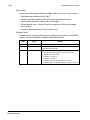
Manual contents
List of included manuals
ACH550-UH Drives. . . . . . . . . . . . . . . . . . . . . . . . . . . . . . . . . . . . . . . . . . . . . . . . 1-1
ACH550-BCR/BDR/VCR/VDR E-Clipse Bypass Drives . . . . . . . . . . . . . . . . . . . 2-1
ACH550-PCR/PDR Packaged Drives with Disconnect . . . . . . . . . . . . . . . . . . . 3-1
Manual contents
iv
Manual contents
ACH550-UH User’s Manual
1-1
ACH550-UH HVAC Drives
1…550 HP
User’s Manual
2010 ABB. All Rights Reserved.
ACH550-UH User’s Manual
1-3
Safety
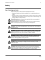
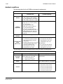
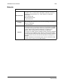
Use of warnings and notes
There are two types of safety instructions throughout this manual:
• Notes draw attention to a particular condition or fact, or give information on a
subject.
• Warnings caution you about conditions which can result in serious injury or death
and/or damage to the equipment. They also tell you how to avoid the danger. The
warning symbols are used as follows:
Electricity warning warns of hazards from electricity which can cause physical
injury and/or damage to the equipment.
General warning warns about conditions, other than those caused by electricity,
which can result in physical injury and/or damage to the equipment.
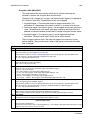
WARNING! The ACH550 adjustable speed AC drive should ONLY be installed by a
qualified electrician.
WARNING! Even when the motor is stopped, dangerous voltage is present at the
power circuit terminals U1, V1, W1 (L1, L2, L3) and U2, V2, W2 (T1, T2 T3) and,
depending on the frame size, UDC+ and UDC-, or BRK+ and BRK-.
WARNING! Dangerous voltage is present when input power is connected. After
disconnecting the supply, wait at least 5 minutes (to let the intermediate circuit
capacitors discharge) before removing the cover.
WARNING! Even when power is switched off from the input terminals of the
ACH550, there may be dangerous voltage (from external sources) on the terminals
of the relay outputs.
WARNING! When the control terminals of two or more drives are connected in
parallel, the auxiliary voltage for these control connections must be taken from a
single source which can either be one of the drives or an external supply.
Safety
1-4
ACH550-UH User’s Manual
WARNING! Disconnect the internal EMC filter when installing the drive on an IT
system (an ungrounded power system or a high-resistance-grounded [over 30 ohm]
power system).
WARNING! Do not attempt to install or remove EM1, EM3, F1 or F2 screws while
power is applied to the drive’s input terminals.
WARNING! Do not control the motor with the disconnecting device (disconnecting
means); instead, use the control panel keys or commands via the I/O board of the
drive. The maximum allowed number of charging cycles of the DC capacitors (i.e.
power-ups by applying power) is five in ten minutes.
WARNING! Never attempt to repair a malfunctioning ACH550; contact the factory or
your local Authorized Service Center for repair or replacement.
WARNING! The ACH550 will start up automatically after an input voltage
interruption if the external run command is on.
WARNING! The heat sink may reach a high temperature.
Note: For more technical information, contact the factory or your local ABB
representative.
Safety
ACH550-UH User’s Manual
1-5
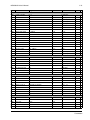
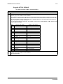
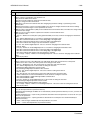
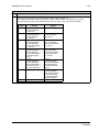
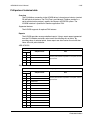
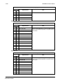
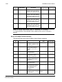
Table of contents
Safety
Use of warnings and notes . . . . . . . . . . . . . . . . . . . . . . . . . . . . . . . . . . . . . . . 1-3
Table of contents
Installation
Installation flow chart . . . . . . . . . . . . . . . . . . . . . . . . . . . . . . . . . . . . . . . . . . . 1-9
Preparing for installation . . . . . . . . . . . . . . . . . . . . . . . . . . . . . . . . . . . . . . . . 1-10
Installing the drive . . . . . . . . . . . . . . . . . . . . . . . . . . . . . . . . . . . . . . . . . . . . 1-13
Control panel
HVAC control panel features . . . . . . . . . . . . . . . . . . . . . . . . . . . . . . . . . . . . 1-33
HVAC control panel modes . . . . . . . . . . . . . . . . . . . . . . . . . . . . . . . . . . . . . 1-34
Start-up
Start-up . . . . . . . . . . . . . . . . . . . . . . . . . . . . . . . . . . . . . . . . . . . . . . . . . . . . . 1-47
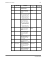
Application macros
Overview . . . . . . . . . . . . . . . . . . . . . . . . . . . . . . . . . . . . . . . . . . . . . . . . . . .
HVAC Default macro . . . . . . . . . . . . . . . . . . . . . . . . . . . . . . . . . . . . . . . . . .
Supply Fan macro . . . . . . . . . . . . . . . . . . . . . . . . . . . . . . . . . . . . . . . . . . . .
Return Fan macro . . . . . . . . . . . . . . . . . . . . . . . . . . . . . . . . . . . . . . . . . . . .
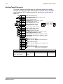
Cooling Tower Fan macro . . . . . . . . . . . . . . . . . . . . . . . . . . . . . . . . . . . . . .
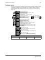
Condenser macro . . . . . . . . . . . . . . . . . . . . . . . . . . . . . . . . . . . . . . . . . . . . .
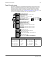
Booster Pump macro . . . . . . . . . . . . . . . . . . . . . . . . . . . . . . . . . . . . . . . . . .
Pump Alternation macro . . . . . . . . . . . . . . . . . . . . . . . . . . . . . . . . . . . . . . . .
Internal Timer macro . . . . . . . . . . . . . . . . . . . . . . . . . . . . . . . . . . . . . . . . . .
Internal Timer with Constant Speeds / PRV macro . . . . . . . . . . . . . . . . . . .
Floating Point macro . . . . . . . . . . . . . . . . . . . . . . . . . . . . . . . . . . . . . . . . . .
Dual Setpoint with PID macro . . . . . . . . . . . . . . . . . . . . . . . . . . . . . . . . . . .
Dual Setpoint with PID and Constant Speeds . . . . . . . . . . . . . . . . . . . . . . .
E-bypass macro . . . . . . . . . . . . . . . . . . . . . . . . . . . . . . . . . . . . . . . . . . . . . .
Hand Control macro . . . . . . . . . . . . . . . . . . . . . . . . . . . . . . . . . . . . . . . . . . .
E-Clipse macro . . . . . . . . . . . . . . . . . . . . . . . . . . . . . . . . . . . . . . . . . . . . . . .
1-49
1-51
1-52
1-53
1-54
1-55
1-56
1-57
1-58
1-59
1-60
1-61
1-62
1-63
1-64
1-65
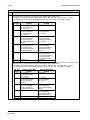
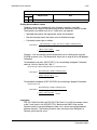
Parameters
Complete parameter list . . . . . . . . . . . . . . . . . . . . . . . . . . . . . . . . . . . . . . . . 1-67
Complete parameter descriptions . . . . . . . . . . . . . . . . . . . . . . . . . . . . . . . . 1-80
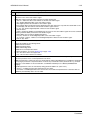
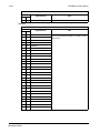
Table of contents
1-6
ACH550-UH User’s Manual
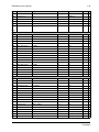
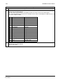
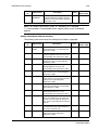
Embedded fieldbus
Overview . . . . . . . . . . . . . . . . . . . . . . . . . . . . . . . . . . . . . . . . . . . . . . . . . . .
Mechanical and electrical installation – EFB . . . . . . . . . . . . . . . . . . . . . . .
Communication setup – EFB . . . . . . . . . . . . . . . . . . . . . . . . . . . . . . . . . . .
Activate drive control functions – EFB . . . . . . . . . . . . . . . . . . . . . . . . . . . .
Feedback from the drive – EFB . . . . . . . . . . . . . . . . . . . . . . . . . . . . . . . . .
Diagnostics – EFB . . . . . . . . . . . . . . . . . . . . . . . . . . . . . . . . . . . . . . . . . . .
N2 protocol technical data . . . . . . . . . . . . . . . . . . . . . . . . . . . . . . . . . . . . .
FLN protocol technical data . . . . . . . . . . . . . . . . . . . . . . . . . . . . . . . . . . . .
BACnet protocol technical data . . . . . . . . . . . . . . . . . . . . . . . . . . . . . . . . .
Modbus protocol technical data . . . . . . . . . . . . . . . . . . . . . . . . . . . . . . . . .
ABB control profiles technical data . . . . . . . . . . . . . . . . . . . . . . . . . . . . . . .
1-187
1-189
1-191
1-195
1-200
1-202
1-207
1-215
1-229
1-241
1-249
Fieldbus adapter
Overview . . . . . . . . . . . . . . . . . . . . . . . . . . . . . . . . . . . . . . . . . . . . . . . . . . .
Mechanical and electrical installation – FBA . . . . . . . . . . . . . . . . . . . . . . .
Communication setup – FBA . . . . . . . . . . . . . . . . . . . . . . . . . . . . . . . . . . .
Activate drive control functions – FBA . . . . . . . . . . . . . . . . . . . . . . . . . . . .
Feedback from the drive – FBA . . . . . . . . . . . . . . . . . . . . . . . . . . . . . . . . .
Diagnostics – FBA . . . . . . . . . . . . . . . . . . . . . . . . . . . . . . . . . . . . . . . . . . .
ABB drives profile technical data . . . . . . . . . . . . . . . . . . . . . . . . . . . . . . . .
Generic profile technical data . . . . . . . . . . . . . . . . . . . . . . . . . . . . . . . . . . .
1-261
1-264
1-265
1-265
1-268
1-269
1-271
1-279
Diagnostics
Diagnostic displays . . . . . . . . . . . . . . . . . . . . . . . . . . . . . . . . . . . . . . . . . . . 1-281
Correcting faults . . . . . . . . . . . . . . . . . . . . . . . . . . . . . . . . . . . . . . . . . . . . . 1-282
Correcting alarms . . . . . . . . . . . . . . . . . . . . . . . . . . . . . . . . . . . . . . . . . . . . 1-288
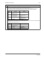
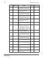
Maintenance
Maintenance intervals . . . . . . . . . . . . . . . . . . . . . . . . . . . . . . . . . . . . . . . . .
Heatsink . . . . . . . . . . . . . . . . . . . . . . . . . . . . . . . . . . . . . . . . . . . . . . . . . . .
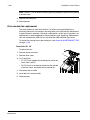
Drive module fan replacement . . . . . . . . . . . . . . . . . . . . . . . . . . . . . . . . . .
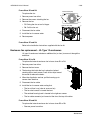
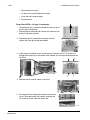
Enclosure fan replacement – UL Type 12 enclosures . . . . . . . . . . . . . . . .
Enclosure air filter replacement – UL Type 12 enclosures . . . . . . . . . . . . .
Capacitors . . . . . . . . . . . . . . . . . . . . . . . . . . . . . . . . . . . . . . . . . . . . . . . . . .
Control panel . . . . . . . . . . . . . . . . . . . . . . . . . . . . . . . . . . . . . . . . . . . . . . .
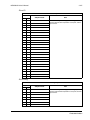
Table of contents
1-291
1-291
1-292
1-293
1-295
1-298
1-298
ACH550-UH User’s Manual
1-7
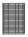
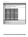
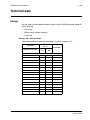
Technical data
Ratings . . . . . . . . . . . . . . . . . . . . . . . . . . . . . . . . . . . . . . . . . . . . . . . . . . . .
Input power connections . . . . . . . . . . . . . . . . . . . . . . . . . . . . . . . . . . . . . .
Motor connections . . . . . . . . . . . . . . . . . . . . . . . . . . . . . . . . . . . . . . . . . . .
Control connections . . . . . . . . . . . . . . . . . . . . . . . . . . . . . . . . . . . . . . . . . .
Efficiency . . . . . . . . . . . . . . . . . . . . . . . . . . . . . . . . . . . . . . . . . . . . . . . . . .
Cooling . . . . . . . . . . . . . . . . . . . . . . . . . . . . . . . . . . . . . . . . . . . . . . . . . . . .
Dimensions and weights . . . . . . . . . . . . . . . . . . . . . . . . . . . . . . . . . . . . . .
Degrees of protection . . . . . . . . . . . . . . . . . . . . . . . . . . . . . . . . . . . . . . . . .
Ambient conditions . . . . . . . . . . . . . . . . . . . . . . . . . . . . . . . . . . . . . . . . . . .
Materials . . . . . . . . . . . . . . . . . . . . . . . . . . . . . . . . . . . . . . . . . . . . . . . . . . .
Applicable standards . . . . . . . . . . . . . . . . . . . . . . . . . . . . . . . . . . . . . . . . .
Liability limits . . . . . . . . . . . . . . . . . . . . . . . . . . . . . . . . . . . . . . . . . . . . . . .
1-299
1-303
1-311
1-317
1-320
1-320
1-322
1-327
1-328
1-329
1-330
1-332
Index
Table of contents
1-8
Table of contents
ACH550-UH User’s Manual
ACH550-UH User’s Manual
1-9
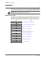
Installation
Study these installation instructions carefully before proceeding. Failure to observe
the warnings and instructions may cause a malfunction or personal hazard.
WARNING! Before you begin read Safety on page 1-3.
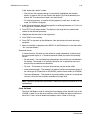
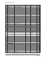
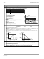
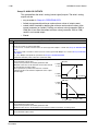
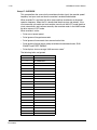
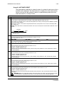
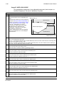
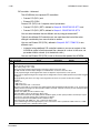
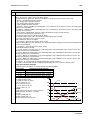
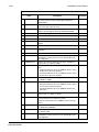
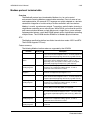
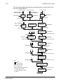
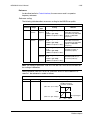
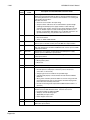
Installation flow chart
The installation of the ACH550 adjustable speed AC drive follows the outline below.
The steps must be carried out in the order shown. At the right of each step are
references to the detailed information needed for the correct installation of the unit.
Task
See
PREPARE for installation
Preparing for installation on page 1-10.
PREPARE the mounting location
Prepare the mounting location on page 1-14.
REMOVE the front cover
Remove front cover on page 1-16.
MOUNT the drive
Mount the drive on page 1-17.
INSTALL wiring
Wiring overview on page 1-18 and
Install the wiring on page 1-23.
CHECK installation
Check installation on page 1-27.
REINSTALL the cover
Re-install cover on page 1-27.
APPLY power
Apply power on page 1-29.
START-UP
Start-up on page 1-30.
Installation
1-10
ACH550-UH User’s Manual
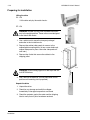
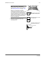
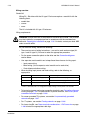
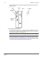
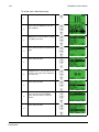
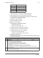
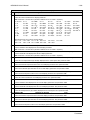
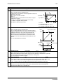
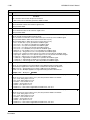
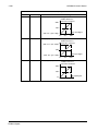
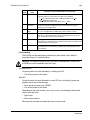
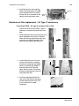
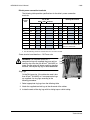
Preparing for installation
Lifting the drive
R1…R6
Lift the drive only by the metal chassis.
IP2040
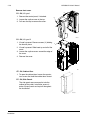
R7…R8
WARNING! Handle and ship floor mounted enclosures
only in the upright position. These units are not designed
to be laid on their backs.
1. Use a pallet truck to move the transport package/
enclosure to the installation site.
PC00005
2. Remove the cabinet side panels for access to the
cabinet/pallet mounting bolts. (6 torx screws hold each
cabinet side panel in place. Leave the side panels off
until later.)
2
3. Remove the 4 bolts that secure the cabinet to the
shipping pallet.
R70010
WARNING! Use the lifting lugs/bars at the top of the unit
to lift R7/R8 drives.
30o
4. Use a hoist to lift the drive. (Do not place drive in final
position until mounting site is prepared.)
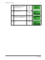
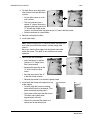
Unpack the drive
1. Unpack the drive.
2. Check for any damage and notify the shipper
immediately if damaged components are found.
3. Check the contents against the order and the shipping
label to verify that all parts have been received.
Installation
PC00003
ACH550-UH User’s Manual
1-11
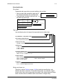
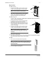
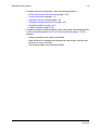
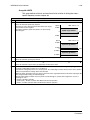
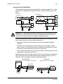
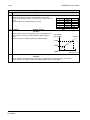
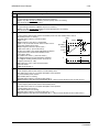
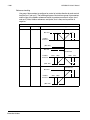
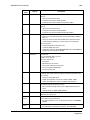
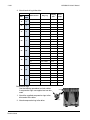
Drive identification
Drive labels
To determine the type of drive you are installing, refer to either:
• Serial number label attached on upper part of
the chokeplate between the mounting holes.
SW:
V.2.06B
2030700001
ACH550-UH-059A-2
• Type code label attached on the heat sink – on
the side of the enclosure.
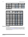
Input
Voltage (U1)
Current (I1n)
3 PH 48…63 Hz
200…240 Vac
59.4 A
1 PH 4…63 Hz
200…240 Vac
59.4 A
Output
Voltage (U2)
Current (I2n)
3 PH 0…500 Hz
0…U1 Vac
59.4 A
3 PH 0…500 Hz
0…U1 Vac
28 A
Power (Pn)
20 HP
10 HP
S/N
2030700001
ABB Inc.
Made in USA of foreign parts
kAIC
Mfg. Date: 01-December-2005
S/N
Org. Firmware: V.2.06B
2030700001
ACH550-UH-059A-2
Type code
Use the following chart to interpret the type code found on either label.
ACH550-UH-08A8-4+...
AC, HVAC Drive – 550 product series
Construction (region specific)
UH = Setup and parts specific to US installation and NEMA compliance
Output current rating
e.g. 08A8 = 8.8A See section Ratings for details on page 1-299
Voltage rating
2 = 208…240 VAC
4 = 380…480 VAC
6 = 500…600 VAC
Enclosure protection class
No specification = UL type 1 / NEMA 1 / IP 21
+B055 = UL type 12 / NEMA 12 / IP 54
Fieldbus Adapter
+K451 = DeviceNet Adapter
+K452 = LonWorks Adapter
+K454 = Profibus Adapter
+K462 = ControlNet Adapter
+K466 = EtherNet Adapter
I/O Options
+L511 = Relay Output Extension
+L512 = 115/230 V Digital Input Interface
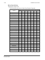
Ratings and frame size
The chart in section Ratings on page 1-299 lists technical specifications, and
identifies the drive’s frame size. To read the Ratings table, you need the “Output
current rating” entry from the type code (see above). Also, when using the Ratings
tables, note that there are different tables for each drive “Voltage rating”.
Installation
1-12
ACH550-UH User’s Manual
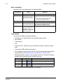
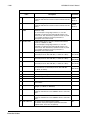
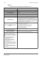
Motor compatibility
The motor, drive, and supply power must be compatible:
Motor
Specification
Verify
Reference
Motor type
3-phase induction motor
–
Nominal current
Motor value is within this
range: 0.15…1.5 * I2N
(I2N = normal use current)
• Type code label on drive, entry for Output I2N,
or
• Type code on drive and rating table in
Technical data on page 1-299.
Nominal frequency
10…500 Hz
–
Voltage range
Motor is compatible with
208…240 V (for ACH550-xx-xxxx-2) or
the ACH550 voltage range. 380…480 V (for ACH550-xx-xxxx-4)
500…600 V (for ACH550-xx-xxxx-6)
Insulation
500…600 V drives: Either
the motor complies with
NEMA MG1 Part 31, or a
du/dt filter is used between
the motor and drive.
For ACH550-xx-xxxx-6
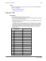
Tools required
To install the ACH550 you need the following:
• Screwdrivers (as appropriate for the mounting hardware used)
• Wire stripper
• Tape measure
• Drill
• Frame sizes R5…R8 with UL type 12 enclosure: Punch for conduit mounting
holes
• Frame sizes R7/R8: pallet truck and hoist
• For installations involving frame size R6…R8: The appropriate crimping tool for
power cable lugs. See Power terminal considerations – R6 Frame size.
• Mounting hardware: screws or nuts and bolts, four each. The type of hardware
depends on the mounting surface and the frame size:
Frame Size
Mounting Hardware
R1…R4
M5
#10
R5
M6
1/4 in
R6
M8
5/16 in
R7…R8
M10
7/16
Note
Secures free standing cabinets if required.
• For installations involving frame size R7…R8: Hoist.
Installation
ACH550-UH User’s Manual
1-13
Suitable environment and enclosure
Confirm that the site meets the environmental requirements. To prevent damage
prior to installation, store and transport the drive according to the environmental
requirements specified for storage and transportation. See Ambient conditions on
page 1-328.
Confirm that the enclosure is appropriate, based on the site contamination level:
• UL type 1 enclosure. The site must be free of airborne dust, corrosive gases or
liquids, and conductive contaminants such as condensation, carbon dust, and
metallic particles.
• UL type 12 enclosure. This enclosure provides protection from airborne dust and
light sprays or splashing water from all directions.
Suitable mounting location
Confirm that the mounting location meets the following constraints:
• R1…R6: The drive must be mounted vertically on a smooth, solid surface, and in
a suitable environment as defined above.
• The drive must be located in a suitable environment as defined above.
• The minimum space requirements for the drive are the outside dimensions (see
Outside dimensions – R1…R6 on page 1-325 or Outside dimensions – R7…R8
on page 1-326), plus air flow space around the unit (see Cooling on page 1-320).
• The distance between the motor and the drive is limited by the maximum motor
cable length. See either Motor connection specifications on page 1-311, or
EN 61800-3 compliant motor cables on page 1-314.
• The mounting site must support the drive’s weight. See Weight on page 1-324.
Installing the drive
WARNING! Before installing the ACH550, ensure the input power supply to the drive
is off.
WARNING! Metal shavings or debris in the enclosure can damage electrical
equipment and create a hazardous condition. Where parts, such as conduit plates
require cutting or drilling, first remove the part. If that is not practical, cover nearby
electrical components to protect them from all shavings or debris.
Installation
1-14
ACH550-UH User’s Manual
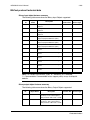
For flange mounting (mounting the drive in a cooling air duct), see the appropriate
Flange Mounting Instructions:
Frame size
IP21 / UL type 1
Kit
IP54 / UL type 12
Code (English)
Kit
Code (English)
R1
FMK-A-R1
100000982
FMK-B-R1
100000990
R2
FMK-A-R2
100000984
FMK-B-R2
100000992
R3
FMK-A-R3
100000986
FMK-B-R3
100000994
R4
FMK-A-R4
100000988
FMK-B-R4
100000996
R5
AC8-FLNGMT-R5
ACS800-PNTG01U-EN
-
-
R6
AC8-FLNGMT-R6
-
-
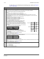
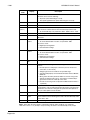
Prepare the mounting location
The ACH550 should only be mounted where all of the
requirements defined in Preparing for installation on
page 1-10 are met.
1. Mark the position of the mounting holes.
1
X0002
Note: Frame sizes R3 and R4 have four holes along the top. Use only two. If
possible, use the two outside holes (to allow room to remove the fan for
maintenance).
Note: ACH400 drives can be replaced using the original mounting holes. For R1 and
R2 frame sizes, the mounting holes are identical. For R3 and R4 frame sizes, the
inside mounting holes on the top of ACH550 drives match ACH400 mounts.
Installation
ACH550-UH User’s Manual
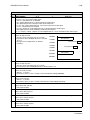
1-15
Note: Frame sizes R7 and R8 have
mounting holes inside the enclosure base.
See Mounting dimensions on page 1-323.
Where it is not possible to use either
mounting hole at the back of the base, use
an L-bracket at the top of the enclosure to
secure the cabinet to a wall or to the back of
another enclosure. Bolt the L-bracket to the
enclosure using the lifting lug bolt hole on
the top of the enclosure.
PC00023
Fastening points when installed
back against a wall (Top view)
Fastening points when installed
back against back
2. Drill holes of appropriate size in the
mounting location.
Fastening the cabinet at the top
using L-brackets (side view)
L-bracket
M12 bolt (1/2 to 9/16 in)
Cabinet top
Installation
1-16
ACH550-UH User’s Manual
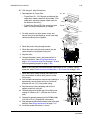
Remove front cover
3
R1…R6, UL type 1
1. Remove the control panel, if attached.
2
2. Loosen the captive screw at the top.
3. Pull near the top to remove the cover.
1
IP2000
R1…R6, UL type 12
1. If hood is present: Remove screws (2) holding
the hood in place.
1
2
2. If hood is present: Slide hood up and off of the
cover.
3. Loosen the captive screws around the edge of
the cover.
4. Remove the cover.
3
4
FM
R7…R8, Cabinet Door
1. To open the cabinet door, loosen the quarterturn screws that hold the cabinet door closed.
1
R7…R8, Side Panels
The side panels were removed to take the
cabinet off the pallet. Installation access is
easier if these panels are kept off throughout
the installation.
R70020
Installation
ACH550-UH User’s Manual
1-17
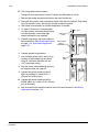
Mount the drive
1
R1…R6, UL type 1
1. Position the ACH550 onto the mounting screws
or bolts and securely tighten in all four corners.
Note: Lift the ACH550 by its metal chassis.
2
2. Non-English speaking locations: Add a warning
sticker in the appropriate language over the
existing warning on the top of the module.
R1…R6, UL type 12
IP2002
For the UL type 12 enclosures, rubber plugs are required in the holes provided for
access to the drive mounting slots.
1. As required for access, remove the rubber plugs.
Push plugs out from the back of the drive.
2. R5 & R6: Align the sheet metal hood (not shown)
in front of the drive’s top mounting holes. (Attach
as part of next step.)
2
1, 3
3. Position the ACH550 onto the mounting screws
or bolts and securely tighten in all four corners.
Note: Lift the ACH550 by its metal chassis
(frame size R6 by the lifting holes on both sides
at the top).
FM
4. Re-install the rubber plugs.
5. Non-English speaking locations: Add a warning sticker in the appropriate language
over the existing warning on the top of the module.
R7…R8
1. Use a hoist to move the cabinet into position.
30o
Note: If the cabinet location does not provide access to
the cabinet sides, be sure to re-mount side panels before
positioning cabinet.
2. Install and tighten mounting bolts.
PC00003
Installation
1-18
ACH550-UH User’s Manual
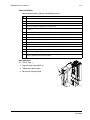
Wiring overview
Conduit kit
Wiring R1…R6 drives with the UL type 1 Enclosure requires a conduit kit with the
following items:
• conduit box
• screws
• cover
The kit is included with UL type 1 Enclosures.
Wiring requirements
WARNING! Ensure the motor is compatible for use with the ACH550. The ACH550
must be installed by a competent person in accordance with the considerations
defined in Preparing for installation on page 1-10. If in doubt, contact your local ABB
sales or service office.
As you install the wiring, observe the following:
• There are two sets of wiring instructions – one set for each enclosure type (UL
type 1 and UL type 12). Be sure to select the appropriate procedure.
• For the power connection points on the drive see the Connection diagrams
section below.
• Use separate, metal conduit runs to keep these three classes of wiring apart:
– Input power wiring.
– Motor wiring. (Use a separate, metal conduit run for each drive)
– Control/communications wiring.
• When installing input power and motor wiring, refer to the following, as
appropriate:
Terminal
Description
Specifications and Notes
U1, V1, W1*
3-phase power supply input
Input power connections on page 1-303.
PE
Protective Ground
Ground connections on page 1-307.
U2, V2, W2
Power output to motor
Motor connections on page 1-311.
* The ACH550 -xx-xxxx-2 (208…240V series) can be used with a single phase supply, if output
current is derated by 50%. For single phase supply voltage connect power at U1 and W1.
• To locate input power and motor connection terminals, see Connection diagrams
starting on page 1-20. For specifications on power terminals, see Drive’s power
connection terminals on page 1-309.
• For corner grounded TN systems, see section Unsymmetrically grounded
networks on page 1-307.
• For IT systems, see section Floating networks on page 1-308.
• For frame size R6, see Power terminal considerations – R6 Frame size on page
1-309 to install the appropriate cable lugs.
Installation
ACH550-UH User’s Manual
1-19
• For details on control connections, refer to the following sections:
– Drive’s control connection terminals on page 1-318.
– Control connections on page 1-317.
– Application macros starting on page 1-49.
– Complete parameter descriptions on page 1-80.
– Embedded fieldbus on page 1-187.
– Fieldbus adapter on page 1-261.
• For electro-magnetic compliance (EMC), follow local codes and the requirements
in Motor cable requirements for CE & C-Tick compliance on page 1-313. For
example:
– Properly ground the wire screen cable shields.
– Keep individual un-screened wires between the cable clamps and the screw
terminals as short as possible.
– Route control cables away from power cables.
Installation
1-20
ACH550-UH User’s Manual
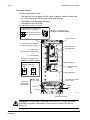
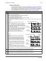
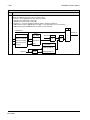
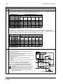
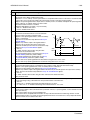
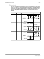
Connection diagrams
The following diagrams show:
• The terminal layout for frame size R3, which, in general, applies to frame sizes
R1…R6, except for the R5/R6 power and ground terminals.
• The R5/R6 power and ground terminals.
• The terminal layout for R7/R8.
R1…R4 (Diagram shows the R3 frame.)
J1 – DIP Switches for Analog Inputs
The switch is one of two types:
ON
Illustration of available switch
positions; not default settings
ON
AI1: (in Voltage Position)
AI2: (in Current Position)
Alternate
Original
Panel Connector
X1 – Analog Inputs and Outputs
(and 10 V Ref. Voltage Output)
Power LED (Green)
Fault LED (Red)
X1 – Digital Inputs
(and 24 V Aux. Voltage Output)
X1 – Relay Outputs
Illustration of available switch
positions; not default settings
Optional Module 1
J2 – DIP Switches
for RS485 Termination
J2
X1 – Communications
(RS485)
J2
ON
Optional Module 2
ON
off position
Frame Sizes
R5/R6 differ.
See next page.
on position
Power Input
(U1, V1, W1)
Power Output to Motor
(U2, V2, W2)
EM3
EM1
GND
PE
X0003
Terminals Not Used
WARNING! To avoid danger, or damage to the drive, on IT systems and corner
grounded TN systems, see section Disconnecting the internal EMC filter on
page 1-22.
Installation
ACH550-UH User’s Manual
1-21
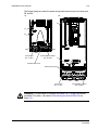
The following diagram shows the power and ground terminal layout for frame sizes
R5 and R6.
R5
R6
F2
F1
F2
PE
GND
X0011
GND
Power Input
(U1, V1, W1)
Power Output to Motor
(U2, V2, W2)
F1
Terminals Not Used
Terminals Not Used
PE
Power Input
(U1, V1, W1)
X0013
GND
Power Output to Motor
(U2, V2, W2)
WARNING! To avoid danger, or damage to the drive, on IT systems and corner
grounded TN systems, see section Disconnecting the internal EMC filter on
page 1-22.
Installation
1-22
ACH550-UH User’s Manual
The following diagram shows the power and ground terminal layout for frame size
R7 (R8 is similar).
R7
Motor
Terminals
Ground Lug
Bar
ACH550
Control Wires
(X1)
Input Power
Terminals
Terminal Strip
Only on
ACH550-UH
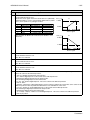
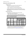
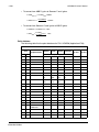
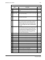
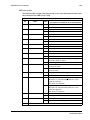
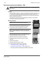
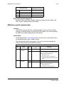
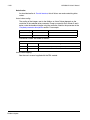
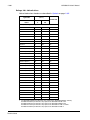
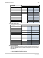
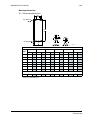
Disconnecting the internal EMC filter
On certain types of systems, you must disconnect the internal EMC filter, otherwise
the system will be connected to ground potential through the EMC filter capacitors,
which might cause danger, or damage the drive.
Note: When the internal EMC filter is disconnected, the drive is not EMC compatible.
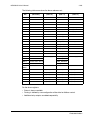
The following table shows the installation rules for the EMC filter screws in order to
connect or disconnect the filter, depending on the system type and the frame size.
For more information on the different system types, see Floating networks on page
1-308 and Unsymmetrically grounded networks on page 1-307.
Installation
ACH550-UH User’s Manual
1-23
The locations of screws EM1 and EM3 are shown in the diagram on page 1-20. The
locations of screws F1 and F2 are shown in the diagram on page 1-21.
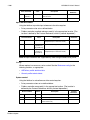
Frame
sizes
R1…R3
R4
R5…R6
Screw
Symmetrically
grounded TN systems
(TN-S systems)
Corner grounded
TN systems
IT systems (ungrounded
or high-resistancegrounded [> 30 ohm])
EM1
x
x
EM3
x
EM1
x
x
–
EM3
x
–
–
F1
x
x
–
F2
x
x
–
x = Install the screw. (EMC filter will be connected.)
= Replace the screw with the provided polyamide screw. (EMC filter will be disconnected.)
– = Remove the screw. (EMC filter will be disconnected.)
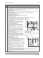
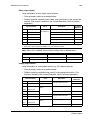
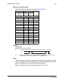
Install the wiring
Checking motor and motor cable insulation
WARNING! Check the motor and motor cable insulation before connecting the drive
to input power. For this test, make sure that motor cables are NOT connected to the
drive.
1. Complete motor cable connections to the motor, but NOT to the drive output
terminals (U2, V2, W2).
2. At the drive end of the motor cable, measure the insulation
resistance between each motor cable phase and Protective
Earth (PE): Apply a voltage of 1 kV DC and verify that
resistance is greater than 1 Mohm.
M
ohm
PE
Installation
1-24
ACH550-UH User’s Manual
R1…R6, wiring UL type 1 enclosure
1. Open the appropriate knockouts in the
conduit box. (See Conduit kit on page 1-18.)
2. Install thin-wall conduit clamps (not supplied).
2
X0007
3. Install conduit box.
4. Connect conduit runs for input power, motor
and control cables to the box.
3
X0005
5. Route input power and motor wiring through
separate conduits.
7
6. Strip wires.
7. Connect power, motor, and ground wires to
the drive terminals. See Wiring requirements
on page 1-18 and table on the tightening
torques on page 1-309.
7
5
4
IP2004
Note: For R5 frame size, the minimum power cable size is 25 mm2 (4 AWG). For R6
frame size, refer to Power terminal considerations – R6 Frame size on page 1-309.
8. Route the control cables through the conduit
(not the same conduit as either input power or
motor wiring).
9. Use available secure points and tie strap
landings to permanently secure control wiring
at a minimum distance of 6 mm (1/4") from
power wiring.
10
12
10. Strip the control cable sheathing and twist the
copper screen into a pig-tail.
11. Connect the ground screen pig-tail for digital
and analog I/O cables at X1-1. (Ground only
at drive end.)
8
12. Connect the ground screen pig-tail for RS485
cables at X1-28 or X1-32. (Ground only at
drive end.)
13. Strip and connect the individual control wires to the drive terminals. See Wiring
requirements on page 1-18.
14. Install the conduit box cover (1 screw).
Installation
IP2005
ACH550-UH User’s Manual
1-25
R1…R6, wiring UL type 12 enclosure
1. Step depends on Frame Size:
• Frame Sizes R1…R4: Remove and discard the
cable seals where conduit will be installed. (The
cable seals are cone-shaped, rubber seals on
the bottom of the drive.)
• Frame Sizes R4 and R5: Use punch to create
holes for conduit connections as needed.
R1…R4
1
IP5013
R5, R6 1
IP5023
2. For each conduit run (input power, motor and
control wiring must be separate), install water tight
conduit connectors (not supplied).
2
IP5006
3. Route the power wiring through conduit.
4. Route the motor wiring through conduit (not the
same conduit as input power wiring run).
6
5. Strip the wires.
6. Connect the power, motor, and ground wires to
the drive terminals. See Wiring requirements on
page 1-18, Connection diagrams on page 1-20 and
table for tightening torques on page 1-309.
3
4
IP5007
Note: For R5 frame size, the minimum power cable size is 25 mm2 (4 AWG). For R6
frame size, refer to Power terminal considerations – R6 Frame size on page 1-309.
7. Route the control cables through the conduit (not
the same conduit as either input power or motor
wiring runs).
8. Use available secure points and tie strap landings to 9…11
permanently secure control wiring at a minimum
distance of 6 mm (1/4") from power wiring.
9. Strip the control cable sheathing and twist the
copper screen into a pig-tail.
10. Connect the ground screen pig-tail for digital and
analog I/O cables at X1-1. (Ground only at drive
end.)
11. Connect the ground screen pig-tail for RS485 cables
at X1-28 or X1-32. (Ground only at drive end.)
7
12. Strip and connect the individual control wires to the drive
terminals. See Wiring requirements on page 1-18.
13. Install the conduit box cover (1 screw).
IP5008
Installation
1-26
ACH550-UH User’s Manual
R7…R8, wiring (both enclosure types)
The figures show connections in the R7 cabinet, the R8 cabinet is similar.
1. Remove the conduit connection plate from the top of the left bay.
2. Route the input power, motor and control cables to the top of the cabinet. Each cable
type (input power, motor, and control) must be in separate conduit.
3. Use punch to create holes for conduit connections as needed.
4. UL type 12 Enclosure: For each conduit
run (input power, motor and control wiring
must be separate), install water tight
conduit connectors (not supplied).
5. Connect input power and motor cables to
the bus terminals. See Wiring requirements
on page 1-18, Connection diagrams on
page 1-20.
Gnd
Input Power
Cable
Terminal Strip
Only on
ACH550-UH
BP0054
6. Connect grounds to ground bar.
7. Use available secure points and tie strap
landings to permanently secure control
wiring at a minimum distance of 6 mm
(1/4") from power wiring.
Gnd
Motor
Cable
8. Strip the control cable sheathing and twist
the copper screen into a pig-tail.
9. Connect the ground screen pig-tail for
digital and analog I/O cables at X1-1.
(Ground only at drive end.)
10. Connect the ground screen pig-tail for
RS485 cables at X1-28 or X1-32. (Ground
only at drive end.)
BP0054
11. Strip and connect the individual control wires to the drive terminals. See Wiring
requirements on page 1-18.
Installation
ACH550-UH User’s Manual
1-27
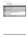
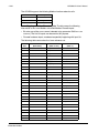
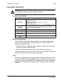
Check installation
Before applying power, perform the following checks.
Check
Installation environment conforms to the drive’s specifications for ambient conditions.
The drive is mounted securely.
Space around the drive meets the drive’s specifications for cooling.
The motor and driven equipment are ready for start.
For floating networks (R1…R6): The internal RFI filter is disconnected (screws EM1 & EM3 or
F1 & F2).
The drive is properly grounded.
The input power voltage matches the drive nominal input voltage range.
The input power connections at U1, V1, and W1 are connected and tightened as specified.
The input power branch circuit protection is installed.
The motor connections at U2, V2, and W2 are connected and tightened as specified.
The input power, motor and control wiring are routed through separate conduit runs.
NO power factor compensation capacitors are in the motor cable.
The control connections are connected and tightened as specified.
NO tools or foreign objects (such as drill shavings) are inside the drive.
NO alternate power source for the motor (such as a bypass connection) is connected – no
voltage is applied to the output of the drive.
Re-install cover
1
R1…R6, UL type 1
1. Align the cover and slide it on.
2. Tighten the captive screw.
2
3. Re-install the control panel.
3
IP2009
Installation
1-28
ACH550-UH User’s Manual
R1…R6, UL type 12
1. Align the cover and slide it on.
2. Tighten the captive screws around the edge of
the cover.
4
3
3. R1…R4: Slide the hood down over the top of
the cover.
4. R1…R4: Install the two screws that attach the
hood.
5
5. Re-install the control panel.
6
Note: The control panel window must be closed
to comply with UL type 12.
6. Optional: Add a lock (not supplied) to secure
the control panel window.
1
2
FM
R7…R8, Covers
1. If side panels were removed and not remounted,
mount them now. Each panel requires 6 torx
screws.
1
2. Re-mount all high voltage shields.
3. Close all internal swing-out panels and secure in
place with the quarter-turn screws.
4. Close the cabinet door and secure in place with
the quarter-turn screws.
Installation
R70020
ACH550-UH User’s Manual
1-29
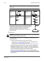
Apply power
Always re-install the covers before turning power on.
WARNING! The ACH550 will start up automatically at power up, if the external run
command is on.
1. Apply input power.
When power is applied to the ACH550, the green LED comes on.
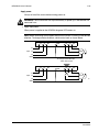
Note: Before increasing motor speed, check that the motor is running in the desired
direction. To change rotation direction, switch motor leads as shown below.
Drive
U1
V1
W1
GND
U2
V2
W2
L1
Motor
Input L2
L3
GND
To change rotation direction,
switch motor leads
Drive
U1
V1
W1
GND
U2
V2
W2
L1
Input L2
L3
GND
Motor
FM
Installation
1-30
ACH550-UH User’s Manual
Start-up
The ACH550 has default parameter settings that are sufficient for many situations.
However, review the following situations. Perform the associated procedures as
appropriate.
Spin motor
When first installed and started the control panel displays a welcome screen with the
following options.
• Press Exit to commission the drive as described in section Start-up by changing
the parameters individually on page 1-47.
• Press Enter to move to the following options:
– Select “Commission Drive” to commission the drive as described in section
Start-Up by Start-up by using the Start-Up Assistant on page 1-47.
– Select “Spin Motor” to operate the motor prior to commissioning. This option
operates the motor without any commissioning, except entry of the motor data
as described below. Spin Motor is useful, for example, to operate ventilation
fans prior to commissioning.
Note: When using Spin Motor, the motor speed is limited to the range 1/3…2/3 of
maximum speed. Also, no interlocks are activated. Finally, once the drive is
commissioned, the welcome screen and this option no longer appear.
Motor data
The motor data on the ratings plate may differ from the defaults in the ACH550. The
drive provides more precise control and better thermal protection if you enter the
rating plate data.
1. Gather the following from the motor ratings plate:
• Voltage
• Nominal motor current
• Nominal frequency
• Nominal speed
• Nominal power
2. Edit parameters 9905…9909 to the correct values.
• Assistant Control Panel: The Start-Up Assistant walks you through this data entry
(see page 1-37).
• Basic Control Panel: Refer to Parameters Mode on page 1-35, for parameter
editing instructions.
Installation
ACH550-UH User’s Manual
1-31
Macros
Note: Selecting the appropriate macro should be part of the original system design,
since the control wiring installed depends on the macro used.
1. Review the macro descriptions in Application macros on page 1-49. Use the macro
that best fits system needs.
2. Edit parameter 9902 to select the appropriate macro. Use either of the following:
• Use the Start-up Assistant, which displays the macro selection immediately after
motor parameter setup.
• Refer to Parameters Mode on page 1-35, for parameter editing instructions.
Tuning – parameters
The system can benefit from one or more of the ACH550 special features, and/or
fine tuning.
1. Review the parameter descriptions in Complete parameter descriptions starting on
page 1-80. Enable options and fine tune parameter values as appropriate for the
system.
2. Edit parameters as appropriate.
Fault and alarm adjustments
The ACH550 can detect a wide variety of potential system problems. For example,
initial system operation may generate faults or alarms that indicate set-up problems.
1. Faults and alarms are reported on the control panel with a number. Note the number
reported.
2. Review the description provided for the reported fault/alarm:
• Use the fault and alarm listings on pages 1-282 and 1-288 respectively, or
• Press the help key (Assistant Control Panel only) while fault or alarm is displayed.
3. Adjust the system or parameters as appropriate.
Installation
1-32
Installation
ACH550-UH User’s Manual
ACH550-UH User’s Manual
1-33
Control panel
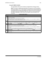
HVAC control panel features
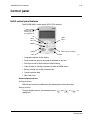
The ACH550 HVAC control panel (ACS-CP-B) features:
Status LED
(Green when normal,
if flashing or red,
see Diagnostics.)
UP
SOFT
KEY 2
SOFT
KEY 1
DOWN
HELP (always available)
AUTO
OFF
HAND
X0201
• Language selection for the display
• Drive connection that can be made or detached at any time
• Start-up assistant to facilitate drive commissioning
• Copy function for moving parameters to other ACH550 drives
• Backup function for saving parameter sets
• Context sensitive help
• Real-time clock
General display features
Soft key functions
The soft key functions are defined by text displayed just above each key.
Display contrast
To adjust display contrast, simultaneously press
appropriate.
and
or
, as
Control panel
1-34
ACH550-UH User’s Manual
HVAC control panel modes
The HVAC control panel has several different modes for configuring, operating and
diagnosing the drive. The modes are:
• Standard Display Mode – Shows drive status information and operates the drive.
• Parameters Mode – Edits parameter values individually.
• Start-up Assistant Mode – Guides the start-up and configuration.
• Changed Parameters Mode – Shows changed parameters.
• Fault Logger Mode – Shows the drive fault history.
• Drive Parameter Backup Mode – Stores or uploads the parameters.
• Clock Set Mode – Sets the time and date for the drive.
• I/O Settings Mode – Checks and edits the I/O settings.
• Alarm Mode – Reporting mode triggered by drive alarms.
Standard Display Mode
Use the Standard Display Mode to read information on the drive’s status and to
operate the drive. To reach the Standard Display Mode, press EXIT until the LCD
display shows status information as described below.
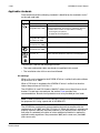
Status information
Top. The top line of the LCD display shows the basic status information of the drive.
• HAND – Indicates that the drive control is local, that is, from the control panel.
• AUTO – Indicates that the drive control is remote, such as the basic I/O (X1) or
fieldbus.
•
– Indicates the drive and motor rotation status as follows:
Control panel display
Significance
Rotating arrow (clockwise or
counterclockwise)
• Drive is running and at setpoint
• Shaft direction is forward or reverse
Rotating dotted arrow blinking
Drive is running but not at setpoint
Stationary dotted arrow
Start command is present, but motor is not
running. E.g. start enable is missing.
• Upper right – shows the active reference.
Middle. Using parameter group 34, the middle of the LCD
display can be configured to display:
• One to three parameter values – The default display shows
parameters 0103 (OUTPUT FREQ) in percentages, 0104
(CURRENT) in amperes and 0120 (AI1) in milliamperes.
– Use parameters 3401, 3408, and 3415 to select the parameters (from Group
01) to display. Entering “parameter” 0100 results in no parameter displayed.
For example, if 3401 = 0100 and 3415 = 0100, then only the parameter
specified by 3408 appears in the Control Panel display.
Control panel
ACH550-UH User’s Manual
1-35
– You can also scale each parameter in the display, for example, to convert the
motor speed to a display of conveyor speed. Parameters 3402…3405 scale
the parameter specified by 3401, parameters 3409…3412 scale the parameter
specified by 3408, etc.
• A bar meter rather than one of the parameter values.
– Enable bar graph displays using parameters 3404, 3411
and 3418.
Bottom. The bottom of the LCD display shows:
• Lower corners – show the functions currently assigned to the two soft keys.
• Lower middle – displays the current time (if configured to show the time).
Operating the drive
AUTO/HAND – The very first time the drive is powered up, it is in the auto control
(AUTO) mode, and is controlled from the Control terminal block X1.
To switch to hand control (HAND) and control the drive using the control panel, press
and hold the
or
button.
• Pressing the HAND button switches the drive to hand control while keeping the
drive running.
• Pressing the OFF button switches to hand control and stops the drive.
To switch back to auto control (AUTO), press and hold the
button.
Hand/Auto/Off – To start the drive press the HAND or AUTO buttons, to stop the
drive press the OFF button.
Reference – To modify the reference (only possible if the display in the upper right
corner is in reverse video) press the UP or DOWN buttons (the reference changes
immediately).
The reference can be modified in the local control mode (HAND/OFF), and can be
parameterized (using Group 11 reference select) to also allow modification in the
remote control mode.
Note: The Start/Stop, Shaft direction and Reference functions are only valid in local
control (HAND/OFF) mode.
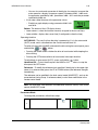
Parameters Mode
To change the parameters, follow these steps:
Select MENU to enter the main menu.
1
Control panel
1-36
ACH550-UH User’s Manual
2
3
4
Select the Parameters mode with the UP/
DOWN buttons, and select ENTER to
select the Parameters Mode.
Select the appropriate parameter group
with the UP/DOWN buttons and select
SEL.
Select the appropriate parameter in a
group with the UP/DOWN buttons. Select
EDIT to change the parameter.
Press the UP/DOWN buttons to change
the parameter value.
5
6
7
Select SAVE to store the modified value
or select CANCEL to leave the set mode.
• Any modifications not saved are
cancelled.
• Each individual parameter setting is
valid immediately after pressing SAVE.
Select EXIT to return to the listing of
parameter groups, and again to return to
the main menu.
For detailed hardware description, see the Appendix.
Note: The current parameter value appears below the highlighted parameter.
Note: To view the default parameter value, press the UP/DOWN buttons
simultaneously.
Note: The most typical and necessary parameters to change are parameter groups
99 Start-up data, 10 Start/Stop/Dir, 11 Reference Select, 20 Limits, 21 Start/Stop, 22
Accel/Decel, 26 Motor Control and 30 Fault Functions.
Note: To restore the default factory settings, select the application macro HVAC
Default.
Control panel
ACH550-UH User’s Manual
1-37
Start-Up Assistant Mode
To start the Start-Up Assistant, follow these steps:
Select MENU to enter the main menu
1
Select ASSISTANTS with the UP/DOWN
buttons and select ENTER.
2
Scroll to COMMISSION DRIVE with the
UP/DOWN buttons and select SEL.
3
4
Change the values suggested by the
assistant to your preferences and then
press SAVE after every change.
The Start-Up Assistant will guide you through the start-up.
The Start-Up Assistant guides you through the basic programming of a new drive.
(You should familiarize yourself with basic control panel operation and follow the
steps outlined above.) At the first start, the drive automatically suggests entering the
first task, Language Select.The assistant also checks the values entered to prevent
entries that are out of range.
The Start-Up Assistant is divided into tasks. You may activate the tasks one after the
other, as the Start-Up Assistant suggests, or independently.
Note: If you want to set the parameters independently, use the Parameters Mode.
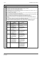
The order of tasks presented by the Start-up Assistant depends on your entries. The
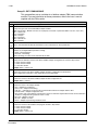
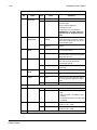
following task list is typical.
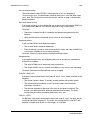
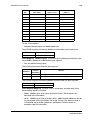
Task name
Description
Spin the motor
• Prompts for control panel display language selection.
• Prompts for motor data.
• Guides user through rotation check.
Commission drive
Prompts for motor data.
Application
Prompts for application macro selection.
References 1 & 2
• Prompts for the source of speed references 1 and 2.
• Prompts for reference limits.
• Prompts for frequency (or speed) limits.
Control panel
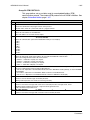
1-38
ACH550-UH User’s Manual
Task name
Description
Start/Stop Control
• Prompts for the source for start and stop commands.
• Prompts for start and stop mode definition.
• Prompts for acceleration and deceleration times.
Protections
•
•
•
•
•
Constant Speeds
• Prompts for the use of constant speeds.
• Prompts for constant speed values.
PID Control
•
•
•
•
•
Low Noise Setup
• Prompts for switching frequency.
• Prompts for definition of Flux optimization.
• Prompts for the use of Critical speeds.
Panel Display
Prompts for display variable and unit settings.
Timed Functions
Prompts for the use of Timed functions.
Output
• Prompts for the signals indicated through the relay outputs.
• Prompts for signals indicated through the analog outputs AO1 and AO2.
Sets the minimum, maximum, scaling and inversion values.
Prompts for current and torque limits.
Prompts for the use of Run enable and Start enable signals.
Prompts for the use of emergency stop.
Prompts for Fault function selection.
Prompts for Auto reset functions selection.
Prompts for PID settings.
Prompts for the source of process reference.
Prompts for reference limits.
Prompts for source, limits and units for the process actual value.
Defines the use of Sleep function.
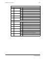
Changed Parameters Mode
To view (and edit) a listing of all parameters that have been changed from macro
default values, follow these steps:
Select MENU to enter the menu.
1
Select CHANGED PAR with the UP/
DOWN buttons and select ENTER.
2
3
Control panel
A list of changed parameters is displayed.
Select EXIT to exit the Changed
Parameters Mode.
ACH550-UH User’s Manual
1-39
Fault Logger Mode
Use the Fault Logger Mode to see drive fault history, fault state details and help for
the faults.
1. Select FAULT LOGGER in the Main Menu.
2. Press ENTER to see the latest faults (up to 10 faults, maximum).
3. Press DETAIL to see details for the selected fault.
• Details are available for the three latest faults.
4. Press DIAG to see the help description for the fault. See Diagnostics section.
Note: If a power off occurs, only the three latest faults will remain (with details only in
the first fault).
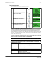
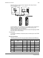
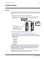
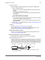
Drive Parameter Backup Mode
Use the Drive Parameter Backup Mode to export parameters from one drive to
another. The parameters are uploaded from a drive to the control panel and
downloaded from the control panel to another drive. Two options are available:
Par Backup Mode
The Assistant Control Panel can store a full set of drive parameters.
The Par Backup Mode has these functions:
• Upload to Panel – Copies all parameters from the drive to the Control Panel.
This includes user sets of parameters (if defined) and internal parameters such as
those created by the Motor Id Run. The Control Panel memory is non-volatile and
does not depend on the panel’s battery. To upload parameters to control panel,
follow these steps:
Select MENU to enter the main
menu.
1
Select PAR BACKUP with the UP/
DOWN buttons and select ENTER.
2
Scroll to Upload to Panel and select
SEL.
3
Control panel
1-40
ACH550-UH User’s Manual
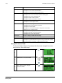
4
5
The text “Copying parameters” and a
progress diagram is displayed.
Select ABORT if you want to stop
the process.
The text “Parameter upload
successful” is displayed and the
control panel returns to the PAR
BACKUP menu. Select EXIT to
return to the main menu. Now you
can disconnect the panel.
• Download Full Set – Restores the full parameter set from the Control Panel to
the drive. Use this option to restore a drive, or to configure identical drives. This
download does not include user sets of parameters.
Upload
to panel
Control
Panel
Download
all
X0202
IP2100
IP2100
To download all parameters to drive, follow these steps:
Select MENU to enter the menu.
1
Select PAR BACKUP with the UP/
DOWN buttons.
2
Scroll to Download to drive all and
select SEL.
3
4
Control panel
The text “Restoring parameters” is
displayed. Select ABORT if you want
to stop the process.
ACH550-UH User’s Manual
1-41
After the download stops, the
message “Parameter download
successful” is displayed and the
control panel goes back to PAR
BACKUP menu. Select EXIT to return
to the main menu.
5
Note: Download Full Set writes all parameters to the drive, including motor
parameters. Only use this function to restore a drive, or to transfer parameters to
systems that are identical to the original system.
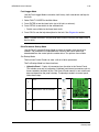
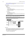
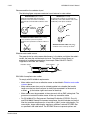
• Download Application – Copies a partial parameter set from the Control Panel
to a drive. The partial set does not include internal motor parameters, parameters
9905…9909, 1605, 1607, 5201, nor any Group 51 and 53 parameters. Use this
option to transfer parameters to systems that use similar configurations – the
drive and motor sizes do not need to be the same.
Upload
to panel
Control
Panel
Download
application
X0202
IP2101
IP2100
To download application to drive, follow these steps:
Select MENU to enter the menu.
1
Select PAR BACKUP with the UP/
DOWN buttons.
2
Scroll to DOWNLOAD APPLICATION
and select SEL.
3
4
The text “Downloading parameters
(partial)” is displayed. Select ABORT
if you want to stop the process.
Control panel
1-42
ACH550-UH User’s Manual
The text “Parameter download
successful” is displayed and the
control panel returns to PAR BACKUP
menu. Select EXIT to return to the
main menu.
5
• Download User Set 1 - Copies USER S1 parameters (user sets are saved using
parameter 9902 APPLIC MACRO) from the Control Panel to the drive.
• Download User Set 2 - Copies USER S2 parameters from the Control Panel to the
drive.
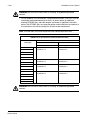
Handling inexact downloads
In some situations, an exact copy of the download is not appropriate for the target
drive. Some examples:
• A download to an old drive specifies parameters/values that are not available on
the old drive.
• A download (from an old drive) to a new drive does not have definitions for the
new parameters – parameters that did not originally exist.
• A download can include an illegal value for the target drive, e.g. a backup from a
small drive can have a switching frequency of 12 kHz whereas a big drive can
only handle 8k Hz.
As a default, the control panel handles these situations by:
• Discarding parameters/values not available on
the target drive.
• Using parameter default values when the
download provides no values or invalid values.
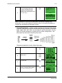
• Providing a Differences List – A listing of the
type and number of items that the target cannot
accept exactly as specified.
LOC
DIFFERENCES ---VALUES UNDER MIN
VALUES OVER MAX
INVALID VALUES
EXTRA PARS
MISSING VALUES
READY
3
2
1
5
7
SEL
You can either accept the default edits by pressing
READY, or view and edit each item as follows:
1. Highlight an item type in the Differences List (left screen below) and press SEL to
see the details for the selected type (right screen below).
LOC
DIFFERENCES ---VALUES UNDER MIN
VALUES OVER MAX
INVALID VALUES
EXTRA PARS
MISSING VALUES
READY
Control panel
3
2
1
5
7
SEL
LOC
INVALID VAL
9902 APLIC MACRO
2606*SWITCHING FREQ
12 kHz
8 kHz
3401*DISP 1 SEL
EXIT
EDIT
ACH550-UH User’s Manual
1-43
In the above-right “details” screen:
• The first item that requires editing is automatically highlighted and includes
details: In general, the first item listed in the details is the value defined by the
backup file. The second item listed is the “default edit.”
• For tracking purposes, an asterisk initially appears by each item. As edits are
made, the asterisks disappear.
2. In the illustrated example, the backup specifies a switching frequency of 12 kHz, but
the target drive is limited to 8 kHz.
3. Press EDIT to edit the parameter. The display is the target drive’s standard edit
screen for the selected parameter.
4. Highlight the desired value for the target drive.
5. Press SAVE to save setting.
6. Press EXIT to step back to the differences view and continue for each remaining
exception.
7. When your editing is complete, press READY in the Differences List and then select
“Yes, save parameters.”
Download failures
In some situations, the drive may be unable to accept a download. In those cases,
the control panel display is: “Parameter download failed” plus one of the following
causes:
• Set not found – You are attempting to download a data set that was not defined in
the backup. The remedy is to manually define the set, or upload the set from a
drive that has the desired set definitions.
• Par lock – The remedy is to unlock the parameter set (parameter 1602).
• Incompat drive/model – The remedy is to perform backups only between drives of
the same type (ACS/industrial or ACH/HVAC) and the same model (all ACH550).
• Too many differences – The remedy is to manually define a new set, or upload the
set from a drive that more closely resembles the target drive.
Note: If upload or download of parameters is aborted, the partial parameter set is not
implemented.
Clock Set Mode
The Clock Set Mode is used for setting the time and date for the internal clock of the
ACH550. In order to use the timer functions of the ACH550, the internal clock has to
be set first. Date is used to determine weekdays and is visible in Fault logs.
Control panel
1-44
ACH550-UH User’s Manual
To set the clock, follow these steps:
Select MENU to enter the main menu.
1
2
3
4
Scroll to Clock Set with the UP/DOWN
buttons and select ENTER to enter the
Clock Set Mode.
Scroll to Clock Visibility with the UP/
DOWN buttons and select SEL to change
the visibility of the clock.
Scroll to Show Clock with the UP/DOWN
buttons and select SEL to make the clock
visible.
Scroll to Set Time with the UP/DOWN
buttons and select SEL.
5
6
Change the hours and minutes with the
UP/DOWN buttons and select OK to save
the values. The active value is displayed
in inverted color.
Scroll to Time Format with the UP/DOWN
buttons and select SEL.
7
8
The different formats are displayed.
Select a format with the UP/DOWN
buttons and select SEL to confirm the
selection.
Scroll to Set Date with the UP/DOWN
buttons and select SEL.
9
Control panel
ACH550-UH User’s Manual
10
1-45
Change the days, months and year with
the UP/DOWN buttons and select OK to
save the values. The active value is
displayed in inverted color.
Scroll to Date Format with the UP/DOWN
buttons and select SEL.
11
12
The Date formats are displayed. Select a
date format with the UP/DOWN buttons
and select OK to confirm the selection.
Select EXIT twice to return to the main
menu.
13
Control panel
1-46
ACH550-UH User’s Manual
I/O Settings Mode
To view and edit the I/O settings, follow these steps:
Select MENU to enter the main menu.
1
Scroll to I/O Settings with the UP/DOWN
buttons and select ENTER.
2
3
Scroll to the I/O setting you want to view
with the UP/DOWN buttons and select
SEL.
Select the setting you want to view with
the UP/DOWN buttons and select OK.
4
5
You can change the value with the UP/
DOWN buttons and save it by selecting
SAVE.
If you do not want to change the setting,
select CANCEL.
Select EXIT to return to the main menu.
6
Control panel
ACH550-UH User’s Manual
1-47
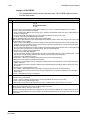
Start-up
Start-up
Start-up can be performed in two ways:
• Using the Start-Up Assistant.
• Changing the parameters individually.
Start-up by using the Start-Up Assistant
To start the Start-Up Assistant, follow these steps:
Select MENU to enter the main menu.
1
Select ASSISTANTS with the Up/Down
buttons and select ENTER.
2
Scroll to COMMISSION DRIVE with the
Up/Down buttons.
3
4
Change the values suggested by the
assistant to your preferences and then
press SAVE after every change.
The Start-Up Assistant will guide you through the start-up.
Start-up by changing the parameters individually
To change the parameters, follow these steps:
Select MENU to enter the main menu.
1
2
Select the Parameters mode with the UP/
DOWN buttons and select ENTER to
select the Parameters mode.
Start-up
1-48
ACH550-UH User’s Manual
3
4
Select the appropriate parameter group
with the UP/DOWN buttons and select
SEL
Select the appropriate parameter in a
group with the UP/DOWN buttons. Select
EDIT to change the parameter value.
Press the UP/DOWN buttons to change
the parameter value.
5
6
7
Select SAVE to store the modified value or
select CANCEL to leave the set mode.
Any modifications not saved are
cancelled.
Select EXIT to return to the listing of
parameter groups, and again to return to
the main menu.
To complete the control connections by manually entering the parameters, see
Parameters Mode on page 1-35.
For detailed hardware description, see the Technical data section on page 1-299.
Note: The current parameter value appears below the highlighted parameter.
Note: To view the default parameter value, press the UP/DOWN buttons
simultaneously.
Note: The most typical and necessary parameters to change are parameter groups
99 Start-up data, 10 Start/Stop/Dir, 11 Reference Select, 20 Limits, 21 Start/Stop, 22
Accel/Decel, 26 Motor Control and 30 Fault Functions.
Note: To restore the default factory settings, select the application macro HVAC
Default.
Start-up
ACH550-UH User’s Manual
1-49
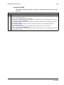
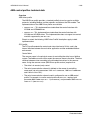
Application macros
Overview
Macros change a group of parameters to new, predefined values designed for
specific applications. Use macros to minimize the need for manual editing of
parameters. Selecting a macro sets all other parameters to their default values,
except:
• Group 99: Start-up Data parameters (except parameter 9904)
• The PARAMETER LOCK 1602
• The PARAM SAVE 1607
• The COMM FAULT FUNC 3018 and COMM FAULT TIME 3019
• The COMM PROT SEL 9802
• Groups 51…53 serial communication parameters
• Group 29: Maintenance triggers
After selecting a macro, additional parameter changes can be made manually using
the control panel.
Application macros are enabled by setting the value for parameter 9902 APPLIC
MACRO. By default, HVAC Default (value 1) is the enabled macro.
General considerations
The following considerations apply for all macros:
• When using a direct speed reference in AUTO mode, connect the speed
reference to analog input 1 (AI1), and provide the START command using digital
input 1 (DI1). In HAND/OFF mode, the control panel provides the speed
reference and START command.
• When using process PID, connect the feedback signal to analog input 2 (AI2). As
a default, the control panel sets the Setpoint, but analog input 1 can be used as
an alternate source. You can set up process PID using parameters (Group 40) or
using the PID control assistant (recommended).
Application macros
1-50
ACH550-UH User’s Manual
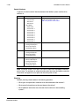
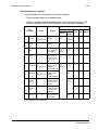
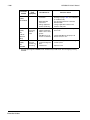
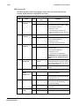
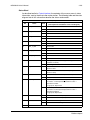
Application / macro listing
This section describes the following macros:
9902
Value
Macro
9902
Value
Macro
1
HVAC Default
9
Internal Timer with Constant Speeds
2
Supply Fan
10
Floating Point
3
Return Fan
11
Dual Setpoint PID
4
Cooling Tower Fan
12
Dual Setpoint PID with Constant Speeds
5
Condenser
13
E-bypass
6
Booster Pump
14
Hand Control
7
Pump Alternation
15
E-Clipse
8
Internal Timer
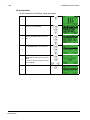
Selecting an application macro
To select a macro, follow these steps:
Select MENU to enter the main menu.
1
Select ASSISTANTS with the UP/DOWN
buttons and select ENTER.
2
Scroll to APPLICATION and select
ENTER.
3
Select a macro with the UP/DOWN buttons
and select SAVE.
4
Restoring defaults
To restore the factory default settings, select the application macro HVAC Default.
Control wiring
Each macro has specific requirements for control wiring. For general details
about the ACH550 control wiring terminals, see Control terminal descriptions on
page 1-318. Specific wiring requirements are included with each macro description.
Application macros
ACH550-UH User’s Manual
1-51
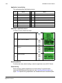
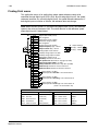
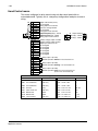
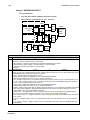
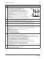
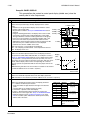
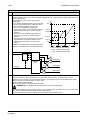
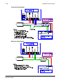
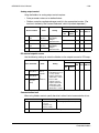
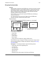
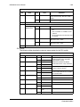
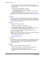
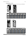
HVAC Default macro
This macro provides the factory default parameter settings for the ACH550-UH.
Factory defaults can be restored at any time by setting parameter 9902 to 1. The
diagram below shows typical wiring using this macro. When using direct speed
reference in AUTO mode or process PID, see General considerations on page 1-49.
+
+
SCR
AI1
AGND
10V
AI2
AGND
AO1
AO2
AGND
Signal cable shield (screen)
External reference 0(2)…10 V or 0(4)…20 mA
Analog input circuit common
Reference voltage 10 VDC
PID feedback: 0(2)…10 V or 0(4)…20 mA
Analog input circuit common
J1 Jumper Settings
ON
Output frequency: 0(4)…20 mA
AI1: 0(4)…20 mA
Output current: 0(4)…20 mA
AI2: 0(4)…20 mA 1 2
Analog output circuit common
10
11
12
13
14
15
16
17
18
24V
GND
DCOM
DI1
DI2
DI3
DI4
DI5
DI6
Auxiliary voltage output +24 VDC
Auxiliary voltage output common
Digital input common for all
Start/Stop: Activate to start drive
Not configured
Constant (Preset) speed 1 (P 1202)
Safety interlock: Deactivate to stop drive (P 1608)
Not configured
Not configured
19
20
21
22
23
24
25
26
27
RO1C
RO1A
RO1B
RO2C
RO2A
RO2B
RO3C
RO3A
RO3B
ON ON
mA
mA
X1 1
2
3
4
5
6
7
8
9
Relay output 1 (P 1401)
Default operation: Ready =>19 connected to 21
Relay output 2 (P 1402)
Default operation: Running =>22 connected to 24
Relay output 3 (P 1403)
Default operation: Fault (-1) =>25 connected to 27
(Fault => 25 connected to 26)
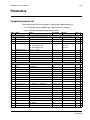
Parameters Changed Relative to HVAC Default
Parameter
Value
Parameter
Value
None (Default macro)
Application macros
1-52
ACH550-UH User’s Manual
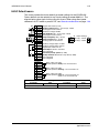
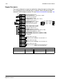
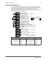
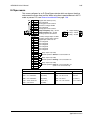
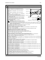
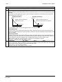
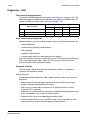
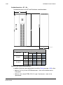
Supply Fan macro
This macro configures for supply fan applications where the supply fan brings fresh
air in according to signals received from a transducer. When using direct speed
reference in AUTO mode or process PID, see General considerations on page 1-49.
+
+
SCR
AI1
AGND
10V
AI2
AGND
AO1
AO2
AGND
Signal cable shield (screen)
External reference 0(2)…10 V or 0(4)…20 mA
Analog input circuit common
Reference voltage 10 VDC
PID feedback: 0(2)…10 V or 0(4)…20 mA
Analog input circuit common
J1 Jumper Settings
ON
Output frequency: 0(4)…20 mA
AI1: 0(4)…20 mA
Output current: 0(4)…20 mA
AI2: 0(4)…20 mA 1 2
Analog output circuit common
10
11
12
13
14
15
16
17
18
24V
GND
DCOM
DI1
DI2
DI3
DI4
DI5
DI6
Auxiliary voltage output +24 VDC
Auxiliary voltage output common
Digital input common for all
Start/Stop: Activate to start drive
Run permissive: Deactivate to stop drive (P 1601)
Constant (Preset) speed 1 (P 12021)
Safety interlock 1: Deactivate to stop drive (P 1608)
Safety interlock 2: Deactivate to stop drive (P 1609)
Not configured
19
20
21
22
23
24
25
26
27
RO1C
RO1A
RO1B
RO2C
RO2A
RO2B
RO3C
RO3A
RO3B
Relay output 1 (P 1401)
Default operation: Started =>19 connected to 21
ON ON
mA
mA
X1 1
2
3
4
5
6
7
8
9
Relay output 2 (P 1402)
Default operation: Running =>22 connected to 24
Relay output 3 (P 1403)
Default operation: Fault (-1) =>25 connected to 27
(Fault => 25 connected to 26)
Parameters Changed Relative to HVAC Default
Parameter
Value
Parameter
Value
9902 APPLIC MACRO
2 (SUPPLY FAN)
1601 RUN ENABLE
2 (DI2)
1401 RELAY OUTPUT 1
7 (STARTED)
1609 START ENABLE 2
5 (DI5)
Application macros
ACH550-UH User’s Manual
1-53
Return Fan macro
This macro configures for return fan applications where the return fan removes air
according to signals received from a transducer. When using direct speed reference
in AUTO mode or process PID, see General considerations on page 1-49.
X1
+
+
SCR
AI1
AGND
10V
AI2
AGND
AO1
AO2
AGND
Signal cable shield (screen)
External reference 0(2)…10 V or 0(4)…20 mA
Analog input circuit common
Reference voltage 10 VDC
PID feedback: 0(2)…10 V or 0(4)…20 mA
Analog input circuit common
J1 Jumper Settings
ON
Output frequency: 0(4)…20 mA
AI1: 0(4)…20 mA
Output current: 0(4)…20 mA
AI2: 0(4)…20 mA 1 2
Analog output circuit common
10
11
12
13
14
15
16
17
18
24V
GND
DCOM
DI1
DI2
DI3
DI4
DI5
DI6
Auxiliary voltage output +24 VDC
Auxiliary voltage output common
Digital input common for all
Start/Stop: Activate to start drive
Run permissive: Deactivate to stop drive (P 1601)
Constant (Preset) speed 1 (P 12021)
Safety interlock 1: Deactivate to stop drive (P 1608)
Safety interlock 2: Deactivate to stop drive (P 1609)
Not configured
19
20
21
22
23
24
25
26
27
RO1C
RO1A
RO1B
RO2C
RO2A
RO2B
RO3C
RO3A
RO3B
Relay output 1 (P 1401)
Default operation: Started =>19 connected to 21
ON ON
mA
mA
1
2
3
4
5
6
7
8
9
Relay output 2 (P 1402)
Default operation: Running =>22 connected to 24
Relay output 3 (P 1403)
Default operation: Fault (-1) =>25 connected to 27
(Fault => 25 connected to 26)
Parameters Changed Relative to HVAC Default
Parameter
Value
9902 APPLIC MACRO
3 (RETURN FAN)
1401 RELAY OUTPUT 1
7 (STARTED)
Parameter
1609 START ENABLE 2
Value
5 (DI5)
Application macros
1-54
ACH550-UH User’s Manual
Cooling Tower Fan macro
This macro configures for cooling tower fan applications where the fan speed is
controlled according to the signals received from a transducer. When using direct
speed reference in AUTO mode or process PID, see General considerations on
page 1-49.
+
+
SCR
AI1
AGND
10V
AI2
AGND
AO1
AO2
AGND
Signal cable shield (screen)
External reference 0(2)…10 V or 0(4)…20 mA
Analog input circuit common
Reference voltage 10 VDC
PID feedback: 0(2)…10 V or 0(4)…20 mA
Analog input circuit common
J1 Jumper Settings
ON
Output frequency: 0(4)…20 mA
AI1: 0(4)…20 mA
Output current: 0(4)…20 mA
AI2: 0(4)…20 mA 1 2
Analog output circuit common
10
11
12
13
14
15
16
17
18
24V
GND
DCOM
DI1
DI2
DI3
DI4
DI5
DI6
Auxiliary voltage output +24 VDC
Auxiliary voltage output common
Digital input common for all
Start/Stop: Activate to start drive
Run permissive: Deactivate to stop drive (P 1601)
Constant (Preset) speed 1 (P 12021)
Safety interlock 1: Deactivate to stop drive (P 1608)
Safety interlock 2: Deactivate to stop drive (P 1609)
Not configured
19
20
21
22
23
24
25
26
27
RO1C
RO1A
RO1B
RO2C
RO2A
RO2B
RO3C
RO3A
RO3B
Relay output 1 (P 1401)
Default operation: Started =>19 connected to 21
ON ON
mA
mA
X1 1
2
3
4
5
6
7
8
9
Relay output 2 (P 1402)
Default operation: Running =>22 connected to 24
Relay output 3 (P 1403)
Default operation: Fault (-1) =>25 connected to 27
(Fault => 25 connected to 26)
Parameters Changed Relative to HVAC Default
Parameter
Value
9902 APPLIC MACRO
4 (CLNG TWR FAN)
2007 MINIMUM FREQ
20.0 Hz
Application macros
Parameter
4005 ERROR VALUE INV
Value
1 (YES)
ACH550-UH User’s Manual
1-55
Condenser macro
This macro configures for condenser and liquid cooler applications where fan speed
is controlled according to signals received from a transducer. When using direct
speed reference in AUTO mode or process PID, see General considerations on
page 1-49.
+
+
SCR
AI1
AGND
10V
AI2
AGND
AO1
AO2
AGND
Signal cable shield (screen)
External reference 0(2)…10 V or 0(4)…20 mA
Analog input circuit common
Reference voltage 10 VDC
PID feedback: 0(2)…10 V or 0(4)…20 mA
Analog input circuit common
J1 Jumper Settings
ON
Output frequency: 0(4)…20 mA
AI1: 0(4)…20 mA
Output current: 0(4)…20 mA
AI2: 0(4)…20 mA 1 2
Analog output circuit common
10
11
12
13
14
15
16
17
18
24V
GND
DCOM
DI1
DI2
DI3
DI4
DI5
DI6
Auxiliary voltage output +24 VDC
Auxiliary voltage output common
Digital input common for all
Start/Stop: Activate to start drive
Run permissive: Deactivate to stop drive (P 1601)
Constant (Preset) speed 1 (P 12021)
Safety interlock 1: Deactivate to stop drive (P 1608)
Safety interlock 2: Deactivate to stop drive (P 1609)
Not configured
19
20
21
22
23
24
25
26
27
RO1C
RO1A
RO1B
RO2C
RO2A
RO2B
RO3C
RO3A
RO3B
Relay output 1 (P 1401)
Default operation: Started =>19 connected to 21
ON ON
mA
mA
X1 1
2
3
4
5
6
7
8
9
Relay output 2 (P 1402)
Default operation: Running =>22 connected to 24
Relay output 3 (P 1403)
Default operation: Fault (-1) =>25 connected to 27
(Fault => 25 connected to 26)
Parameters Changed Relative to HVAC Default
Parameter
9902 APPLIC MACRO
Value
5 (CONDENSER)
Parameter
4005 ERROR VALUE INV
Value
1 (YES)
Application macros
1-56
ACH550-UH User’s Manual
Booster Pump macro
This macro configures for booster pump applications where the pump speed is
controlled according to a signal received from a transducer. When using direct speed
reference in AUTO mode or process PID, see General considerations on page 1-49.
+
+
SCR
AI1
AGND
10V
AI2
AGND
AO1
AO2
AGND
Signal cable shield (screen)
External reference 0(2)…10 V or 0(4)…20 mA
Analog input circuit common
Reference voltage 10 VDC
PID feedback: 0(2)…10 V or 0(4)…20 mA
Analog input circuit common
J1 Jumper Settings
ON
Output frequency: 0(4)…20 mA
AI1: 0(4)…20 mA
Output current: 0(4)…20 mA
AI2: 0(4)…20 mA 1 2
Analog output circuit common
10
11
12
13
14
15
16
17
18
24V
GND
DCOM
DI1
DI2
DI3
DI4
DI5
DI6
Auxiliary voltage output +24 VDC
Auxiliary voltage output common
Digital input common for all
Start/Stop: Activate to start drive
Run permissive: Deactivate to stop drive (P 1601)
Constant (Preset) speed 1 (P 12021)
Safety interlock 1: Deactivate to stop drive (P 1608)
Safety interlock 2: Deactivate to stop drive (P 1609)
Not configured
19
20
21
22
23
24
25
26
27
RO1C
RO1A
RO1B
RO2C
RO2A
RO2B
RO3C
RO3A
RO3B
Relay output 1 (P 1401)
Default operation: Started =>19 connected to 21
ON ON
mA
mA
X1 1
2
3
4
5
6
7
8
9
Relay output 2 (P 1402)
Default operation: Running =>22 connected to 24
Relay output 3 (P 1403)
Default operation: Fault (-1) =>25 connected to 27
(Fault => 25 connected to 26)
Parameters Changed Relative to HVAC Default
Parameter
Value
Parameter
Value
9902 APPLIC MACRO
6 (BOOSTER PUMP)
2202 ACCELER TIME 1
10.0 s
2101 START FUNCTION
8 (RAMP)
2203 DECELER TIME 1
10.0 s
Application macros
ACH550-UH User’s Manual
1-57
Pump Alternation macro
This macro configures for pump alternation applications, usually used in booster
stations. To adjust/maintain pressure in the network, the speed of the one pump
changes according to a signal received from a pressure transducer. When the
variable speed pump reaches a maximum speed limit, auxiliary pumps start as
needed. When using process PID, see General considerations on page 1-49. To use
more than one (the default) Auxiliary pump, see parameter group 81.
+
+
SCR
AI1
AGND
10V
AI2
AGND
AO1
AO2
AGND
Signal cable shield (screen)
External reference 0(2)…10 V or 0(4)…20 mA
Analog input circuit common
Reference voltage 10 VDC
PID feedback: 0(2)…10 V or 0(4)…20 mA
Analog input circuit common
J1 Jumper Settings
ON
Output frequency: 0(4)…20 mA
AI1: 0(4)…20 mA
Output current: 0(4)…20 mA
AI2: 0(4)…20 mA 1 2
Analog output circuit common
10
11
12
13
14
15
16
17
18
24V
GND
DCOM
DI1
DI2
DI3
DI4
DI5
DI6
Auxiliary voltage output +24 VDC
Auxiliary voltage output common
Digital input common for all
Start/Stop: Activate to start drive
Run permissive: Deactivate to stop drive (P 1601)
Not configured
PFA interlock 1: Deactivate to stop drive (P 1608)
PFA interlock 2: Deactivate to stop drive (P 1609)
Not configured
19
20
21
22
23
24
25
26
27
RO1C
RO1A
RO1B
RO2C
RO2A
RO2B
RO3C
RO3A
RO3B
ON ON
mA
mA
X1 1
2
3
4
5
6
7
8
9
Relay output 1 (P 1401)
Default operation: PFA (starts lag pump)
Relay output 2 (P 1402)
Default operation: Running =>22 connected to 24
Relay output 3 (P 1403)
Default operation: Fault (-1) =>25 connected to 27
(Fault => 25 connected to 26)
Parameters Changed Relative to HVAC Default
Parameter
Value
Parameter
Value
9902 APPLIC MACRO
7 (PUMP ALTERNA)
2203 DECELER TIME 1
10.0 s
1201 CONST SPEED SEL
0 (NOT SEL)
8109 START FREQ 1
58.0 HZ
1401 RELAY OUTPUT 1
31 (PFA)
8110
START FREQ
2
58.0 HZ
1608 START ENABLE 1
0 (NOT SEL)
8111
START FREQ
3
58.0 HZ
2101 START FUNCTION
8 (RAMP)
8123 PFA ENABLE
2202 ACCELER TIME 1
10.0 s
1 (ACTIVE)
Application macros
1-58
ACH550-UH User’s Manual
Internal Timer macro
This macro configures for applications where a built-in timer starts and stops the
motor. When the variable speed pump reaches a maximum speed limit, auxiliary
pumps start as needed. When using direct speed reference in AUTO mode or
process PID, see General considerations on page 1-49.
Momentarily activating digital input 3 (DI3) provides a boost function which operates
the motor. See group 36, Timer Functions, for more information on setting up timers.
+
+
SCR
AI1
AGND
10V
AI2
AGND
AO1
AO2
AGND
Signal cable shield (screen)
External reference 0(2)…10 V or 0(4)…20 mA
Analog input circuit common
Reference voltage 10 VDC
PID feedback: 0(2)…10 V or 0(4)…20 mA
Analog input circuit common
J1 Jumper Settings
ON
Output frequency: 0(4)…20 mA
AI1: 0(4)…20 mA
Output current: 0(4)…20 mA
AI2: 0(4)…20 mA 1 2
Analog output circuit common
10
11
12
13
14
15
16
17
18
24V
GND
DCOM
DI1
DI2
DI3
DI4
DI5
DI6
Auxiliary voltage output +24 VDC
Auxiliary voltage output common
Digital input common for all
Timer enable: Activate to start/stop drive from timer
Run permissive: Deactivate to stop drive (P 1601)
Timer override: Activate to start drive
Safety interlock 1: Deactivate to stop drive (P 1608)
Safety interlock 2: Deactivate to stop drive (P 1609)
Not configured
19
20
21
22
23
24
25
26
27
RO1C
RO1A
RO1B
RO2C
RO2A
RO2B
RO3C
RO3A
RO3B
Relay output 1 (P 1401)
Default operation: Started =>19 connected to 21
ON ON
mA
mA
X1 1
2
3
4
5
6
7
8
9
Relay output 2 (P 1402)
Default operation: Running =>22 connected to 24
Relay output 3 (P 1403)
Default operation: Fault (-1) =>25 connected to 27
(Fault => 25 connected to 26)
Parameters Changed Relative to HVAC Default
Parameter
Value
Parameter
Value
9902 APPLIC MACRO
8 (INT TIMER)
1601 RUN ENABLE
1001 EXT1 COMMANDS
11 (TIMER 1)
1609 START ENABLE 2
5 (DI5)
1002 EXT2 COMMANDS
11 (TIMER 1)
3601 TIMERS ENABLE
1 (DI1)
1201 CONST SPEED SEL
0 (NOT SEL)
3622 BOOST SEL
3 (DI3)
1401 RELAY OUTPUT 1
7 (STARTED)
3626 TIMER 1 SRC
31 (P1+2+3+4+B)
Application macros
2 (DI2)
ACH550-UH User’s Manual
1-59
Internal Timer with Constant Speeds / PRV macro
This macro configures for applications such as a timed powered roof ventilator
(PRV) which alternates between two constant speeds (constant speed 1 and 2)
based on a built-in timer.
Momentarily activating digital input 3 (DI3) provides a boost function which operates
the motor. See group 36, Timer Functions, for more information on setting up timers.
+
SCR
AI1
AGND
10V
AI2
AGND
AO1
AO2
AGND
Signal cable shield (screen)
External reference 0(2)…10 V or 0(4)…20 mA
Analog input circuit common
Reference voltage 10 VDC
Not configured
Analog input circuit common
J1 Jumper Settings
Output frequency: 0(4)…20 mA
ON
AI1: 0(4)…20 mA
Output current: 0(4)…20 mA
AI2: 0(4)…20 mA 1 2
Analog output circuit common
10
11
12
13
14
15
16
17
18
24V
GND
DCOM
DI1
DI2
DI3
DI4
DI5
DI6
Auxiliary voltage output +24 VDC
Auxiliary voltage output common
Digital input common for all
Timer enable: Activate to start/stop drive from timer
Run permissive: Deactivate to stop drive (P 1601)
Timer override: Activate to start drive
Safety interlock 1: Deactivate to stop drive (P 1608)
Safety interlock 2: Deactivate to stop drive (P 1609)
Not configured
19
20
21
22
23
24
25
26
27
RO1C
RO1A
RO1B
RO2C
RO2A
RO2B
RO3C
RO3A
RO3B
Relay output 1 (P 1401)
Default operation: Started =>19 connected to 21
ON ON
mA
mA
X1 1
2
3
4
5
6
7
8
9
Relay output 2 (P 1402)
Default operation: Running =>22 connected to 24
Relay output 3 (P 1403)
Default operation: Fault (-1) =>25 connected to 27
(Fault => 25 connected to 26)
Parameters Changed Relative to HVAC Default
Parameter
Parameter
Value
Value
9902 APPLIC MACRO
9 (INT TIMER CS)
3417 SIGNAL 3 MAX
200.0%
1002 EXT2 COMMANDS
0 (NOT SEL)
3419 OUTPUT 3 UNIT
4 (%)
1103
REF1 SEL
0 (KEYPAD)
3420 OUTPUT 3 MIN
-200.0%
1106
REF2 SEL
2 (AI2)
3421 OUTPUT 3 MAX
200.0%
1201 CONST SPEED SEL
15 (TIMER 1)
3601 TIMERS ENABLE
1 (DI1)
1401 RELAY OUTPUT 1
7 (STARTED)
3622 BOOST SEL
3 (DI3)
1601 RUN ENABLE
2 (DI2)
3626 TIMER 1 SRC
31 (P1+2+3+4+B)
1609 START ENABLE 2
5 (DI5)
4010 SET POINT SEL
1 (AI1)
3415 SIGNAL 3 PARAM
0105 (TORQUE)
4110
1 (AI1)
3416 SIGNAL 3 MIN
-200.0%
SET POINT SEL
Application macros
1-60
ACH550-UH User’s Manual
Floating Point macro
This application macro is for applications where speed reference needs to be
controlled through digital inputs (DI5 & DI6). By activating digital input 5, the speed
reference increases, by activating digital input 6, the speed reference decreases. If
both digital inputs are active or inactive, the reference does not change.
Note: When constant speed 1 is activated using digital input 3 (DI3), the reference
speed is the value of parameter 1202. The value remains as the reference speed
when digital input 3 is deactivated.
mA
SCR
AI1
AGND
10V
AI2
AGND
AO1
AO2
AGND
Signal cable shield (screen)
Not configured
Analog input circuit common
Reference voltage 10 VDC
Not configured
Analog input circuit common
Output frequency: 0(4)…20 mA
Output current: 0(4)…20 mA
Analog output circuit common
10
11
12
13
14
15
16
17
18
24V
GND
DCOM
DI1
DI2
DI3
DI4
DI5
DI6
Auxiliary voltage output +24 VDC
Auxiliary voltage output common
Digital input common for all
Start/Stop: Activate to start drive
Run permissive: Deactivate to stop drive (P 1601)
Constant (Preset) speed 1 (P 1202)1
Safety interlock 1: Deactivate to stop drive (P 1608)
Reference up: Activate to increase reference
Reference down: Activate to decrease reference
19
20
21
22
23
24
25
26
27
RO1C
RO1A
RO1B
RO2C
RO2A
RO2B
RO3C
RO3A
RO3B
Relay output 1 (P 1401)
Default operation: Started =>19 connected to 21
ON ON
mA
X1 1
2
3
4
5
6
7
8
9
J1 Jumper Settings
ON
AI1: 0(4)…20 mA
AI2: 0(4)…20 mA 1 2
Relay output 2 (P 1402)
Default operation: Running =>22 connected to 24
Relay output 3 (P 1403)
Default operation: Fault (-1) =>25 connected to 27
(Fault => 25 connected to 26)
Parameters Changed Relative to HVAC Default
Parameter
9902 APPLIC MACRO
1103
Value
Parameter
Value
10 (FLOATING PNT)
3416 SIGNAL 3 MIN
-200.0%
REF1 SEL
7 (DI5U, 6D)
3417 SIGNAL 3 MAX
200.0%
1401 RELAY OUTPUT 1
7 (STARTED)
3419 OUTPUT 3 UNIT
4 (%)
1601 RUN ENABLE
2 (DI2)
3420 OUTPUT 3 MIN
-200.0%
3415 SIGNAL 3 PARAM
0105 (TORQUE)
3421 OUTPUT 3 MAX
200.0%
Application macros
ACH550-UH User’s Manual
1-61
Dual Setpoint with PID macro
This macro configures for dual setpoint PID applications, where activating digital
input 3 (DI3) changes the process PID controller’s setpoint to another value. When
using direct speed reference in AUTO mode or process PID, see General
considerations on page 1-49. Set process PID setpoints (internal to the drive) using
parameters 4011 (SET1) and 4111 (SET2).
+
+
SCR
AI1
AGND
10V
AI2
AGND
AO1
AO2
AGND
Signal cable shield (screen)
External reference 0(2)…10 V or 0(4)…20 mA
Analog input circuit common
Reference voltage 10 VDC
PID feedback: 0(2)…10 V or 0(4)…20 mA
Analog input circuit common
J1 Jumper Settings
ON
Output frequency: 0(4)…20 mA
AI1: 0(4)…20 mA
Output current: 0(4)…20 mA
AI2: 0(4)…20 mA 1 2
Analog output circuit common
10
11
12
13
14
15
16
17
18
24V
GND
DCOM
DI1
DI2
DI3
DI4
DI5
DI6
Auxiliary voltage output +24 VDC
Common for DI return signals.
Auxiliary voltage output common
Start/Stop: Activate to start drive
Run permissive: Deactivate to stop drive (P 1601)
Setpoint selection: Activate to select Set2
Safety interlock 1: Deactivate to stop drive (P 1608)
Safety interlock 2: Deactivate to stop drive (P 1609)
Not configured
19
20
21
22
23
24
25
26
27
RO1C
RO1A
RO1B
RO2C
RO2A
RO2B
RO3C
RO3A
RO3B
Relay output 1 (P 1401)
Default operation: Started =>19 connected to 21
ON ON
mA
mA
X1 1
2
3
4
5
6
7
8
9
Relay output 2 (P 1402)
Default operation: Running =>22 connected to 24
Relay output 3 (P 1403)
Default operation: Fault (-1) =>25 connected to 27
(Fault => 25 connected to 26)
Parameters Changed Relative to HVAC Default
Parameter
Parameter
Value
Value
9902 APPLIC MACRO
11 (DUAL SETPPID)
4010 SET POINT SEL
19 (INTERNAL)
1201 CONST SPEED SEL
0 (NOT SEL)
4011
50.0%
1401 RELAY OUTPUT 1
7 (STARTED)
4027 PID 1 PARAM SET
3 (DI3)
1601 RUN ENABLE
2 (DI2)
4110
SET POINT SEL
19 (INTERNAL)
1609 START ENABLE 2
5 (DI5)
4111
INTERNAL SETPNT
100.0%
INTERNAL SETPNT
Application macros
1-62
ACH550-UH User’s Manual
Dual Setpoint with PID and Constant Speeds
This macro configures for applications with 2 constant speeds, active PID and PID
alternating between two setpoints using digital inputs. Set PID setpoints (internal to
the drive) using parameters 4011 (SET1) and 4111 (SET2). The digital input DI3
selects the setpoints.
+
+
SCR
AI1
AGND
10V
AI2
AGND
AO1
AO2
AGND
Signal cable shield (screen)
External reference 0(2)…10 V or 0(4)…20 mA
Analog input circuit common
Reference voltage 10 VDC
PID feedback: 0(2)…10 V or 0(4)…20 mA
Analog input circuit common
J1 Jumper Settings
ON
Output frequency: 0(4)…20 mA
AI1: 0(4)…20 mA
Output current: 0(4)…20 mA
AI2: 0(4)…20 mA 1 2
Analog output circuit common
10
11
12
13
14
15
16
17
18
24V
GND
DCOM
DI1
DI2
DI3
DI4
DI5
DI6
Auxiliary voltage output +24 VDC
Auxiliary voltage output common
Digital input common for all
Start/Stop: Activate to start drive
Presets/PID selection: Activate to select PID
Setpoint selection: Activate to select Set2
Preset speed 1
Preset speed 2
Not configured
19
20
21
22
23
24
25
26
27
RO1C
RO1A
RO1B
RO2C
RO2A
RO2B
RO3C
RO3A
RO3B
ON ON
mA
mA
X1 1
2
3
4
5
6
7
8
9
Relay output 1 (P 1401)
Default operation: Started =>19 connected to 21
Relay output 2 (P 1402)
Default operation: Running =>22 connected to 24
Relay output 3 (P 1403)
Default operation: Fault (-1) =>25 connected to 27
(Fault => 25 connected to 26)
Parameters Changed Relative to HVAC Default
Parameter
Value
Parameter
Value
12 (DL SP PID CS)
4010 SET POINT SEL
19 (INTERNAL)
2 (DI2)
4011
50.0%
10 (DI4, 5)
4027 PID 1 PARAM SET
3 (DI3)
1608 START ENABLE 1
0 (NOT SEL)
4110
SET POINT SEL
19 (INTERNAL)
2108 START INHIBIT
1 (ON)
4111
INTERNAL SETPNT
100.0%
9902 APPLIC MACRO
1102
EXT1/EXT2 SEL
1201 CONST SPEED SEL
Application macros
INTERNAL SETPNT
ACH550-UH User’s Manual
1-63
E-bypass macro
This macro configures for an E-bypass device which can bypass the drive and
connect the motor direct on-line. When using direct speed reference in AUTO mode
or process PID, see General considerations on page 1-49.
+
+
SCR
AI1
AGND
10V
AI2
AGND
AO1
AO2
AGND
Signal cable shield (screen)
External reference 0(2)…10 V or 0(4)…20 mA
Analog input circuit common
Reference voltage 10 VDC
PID feedback: 0(2)…10 V or 0(4)…20 mA
Analog input circuit common
J1 Jumper Settings
ON
Output frequency: 0(4)…20 mA
AI1: 0(4)…20 mA
Output current: 0(4)…20 mA
AI2: 0(4)…20 mA 1 2
Analog output circuit common
10
11
12
13
14
15
16
17
18
24V
GND
DCOM
DI1
DI2
DI3
DI4
DI5
DI6
Auxiliary voltage output +24 VDC
Auxiliary voltage output common
Digital input common for all
Start/Stop: Activate to start drive
Run enable: Deactivate to stop drive (P 1601)
Not configured
Not configured
Not configured
Not configured
19
20
21
22
23
24
25
26
27
RO1C
RO1A
RO1B
RO2C
RO2A
RO2B
RO3C
RO3A
RO3B
ON ON
mA
mA
X1 1
2
3
4
5
6
7
8
9
Relay output 1 (P 1401)
Default operation: Started =>19 connected to 21
Relay output 2 (P 1402)
Default operation: Running =>22 connected to 24
Relay output 3 (P 1403)
Default operation: Fault (-1) =>25 connected to 27
(Fault => 25 connected to 26)
Parameters Changed Relative to HVAC Default
Value
Parameter
9902 APPLIC MACRO
13 (E-BYPASS)
1601 RUN ENABLE
2 (DI2)
1201 CONST SPEED SEL
0 (NOT SEL)
1608 START ENABLE 1
0 (NOT SEL)
1401 RELAY OUTPUT 1
7 (STARTED)
Parameter
Value
Application macros
1-64
ACH550-UH User’s Manual
Hand Control macro
This macro configures for drive control using only the control panel with no
automated control. Typically, this is a temporary configuration used prior to control
wiring.
mA
SCR
AI1
AGND
10V
AI2
AGND
AO1
AO2
AGND
Signal cable shield (screen)
Not configured
Analog input circuit common
Reference voltage 10 VDC
Not configured
Analog input circuit common
Output frequency: 0(4)…20 mA
Output current: 0(4)…20 mA
Analog output circuit common
10
11
12
13
14
15
16
17
18
24V
GND
DCOM
DI1
DI2
DI3
DI4
DI5
DI6
Auxiliary voltage output +24 VDC
Auxiliary voltage output common
Digital input common for all
Not configured
Not configured
Not configured
Not configured
Not configured
Not configured
19
20
21
22
23
24
25
26
27
RO1C
RO1A
RO1B
RO2C
RO2A
RO2B
RO3C
RO3A
RO3B
ON ON
mA
X1 1
2
3
4
5
6
7
8
9
J1 Jumper Settings
ON
AI1: 0(4)…20 mA
AI2: 0(4)…20 mA 1 2
Relay output 1 (P 1401)
Default operation: Started =>19 connected to 21
Relay output 2 (P 1402)
Default operation: Running =>22 connected to 24
Relay output 3 (P 1403)
Default operation: Fault (-1) =>25 connected to 27
(Fault => 25 connected to 26)
Parameters Changed Relative to HVAC Default
Parameter
Parameter
Value
Value
9902 APPLIC MACRO
14 (HAND CONTROL)
3415 SIGNAL 3 PARAM
0 (NOT SEL)
1001 EXT1 COMMANDS
0 (NOT SEL)
3416 SIGNAL 3 MIN
0
1002 EXT2 COMMANDS
0 (NOT SEL)
3417 SIGNAL 3 MAX
0
2 (AI2)
3419 OUTPUT 3 UNIT
NO UNIT
1201 CONST SPEED SEL
0 (NOT SEL)
3420 OUTPUT 3 MIN
0.0
1504 MINIMUM AO1
0.0 mA
3421 OUTPUT 3 MAX
0.0
1510 MINIMUM AO2
0.0 mA
4010 SET POINT SEL
1 (AI1)
1608 START ENABLE 1
0 (NOT SEL)
4110
1 (AI1)
1106
Application macros
REF2 SEL
SET POINT SEL
ACH550-UH User’s Manual
1-65
E-Clipse macro
This macro configures for an E-Clipse Bypass device which can bypass the drive
and connect the motor direct on-line. When using direct speed reference in AUTO
mode or process PID, see General considerations on page 1-49.
mA
SCR
AI1
AGND
10V
AI2
AGND
AO1
AO2
AGND
Signal cable shield (screen)
Not configured
Analog input circuit common
Reference voltage 10 VDC
Not configured
Analog input circuit common
Output frequency: 0(4)…20 mA
Output current: 0(4)…20 mA
Analog output circuit common
10
11
12
13
14
15
16
17
18
24V
GND
DCOM
DI1
DI2
DI3
DI4
DI5
DI6
Auxiliary voltage output +24 VDC
Auxiliary voltage output common
Digital input common for all
Not configured
Not configured
Not configured
Not configured
Not configured
Not configured
19
20
21
22
23
24
25
26
27
RO1C
RO1A
RO1B
RO2C
RO2A
RO2B
RO3C
RO3A
RO3B
ON ON
mA
X1 1
2
3
4
5
6
7
8
9
J1 Jumper Settings
ON
AI1: 0(4)…20 mA
AI2: 0(4)…20 mA 1 2
Relay output 1 (P 1401)
Default operation: Started =>19 connected to 21
Relay output 2 (P 1402)
Default operation: Running =>22 connected to 24
Relay output 3 (P 1403)
Default operation: Fault (-1) =>25 connected to 27
(Fault => 25 connected to 26)
Parameters Changed Relative to HVAC Default
Parameter
Value
Parameter
Value
9902 APPLIC MACRO
15 (E-CLIPSE)
1608 START ENABLE 1
7 (COMM)
1001 EXT1 COMMANDS
10 (COMM)
5303 EFB BAUD RATE
76.8 KB/S
1002 EXT2 COMMANDS
10 (COMM)
5304 EFB PARITY
2 (8 EVEN 1)
1201 CONST SPEED SEL
0 (NOT SEL)
5305 EFB CTRL PROFILE
1 (DCU PROFILE)
1601 RUN ENABLE
7 (COMM)
Application macros
1-66
Application macros
ACH550-UH User’s Manual
ACH550-UH User’s Manual
1-67
Parameters
Complete parameter list
The following table lists all parameters. Table header abbreviations are:
• S = Parameters can be modified only when the drive is stopped.
• User = Space to enter desired parameter values.
Code
Name
Range
Resolution
Default
User S
Group 99: START-UP DATA
9901
LANGUAGE
0…16
1
0 (ENGLISH)
9902
APPLIC MACRO
-3…15, 31
1
1 (HVAC DEFAULT)
9904
MOTOR CTRL MODE
1, 3
1
3 (SCALAR:FREQ)
9905
MOTOR NOM VOLT
115…345 V (200 V, US)
1V
230 V (US)
230…690 V (400 V, US)
460 V (US)
288…862 V (600 V, US)
575 V (US)
9906
MOTOR NOM CURR
0.15 · I2n … 1.5 · I2n
0.1 A
1.0 · I2n
9907
MOTOR NOM FREQ
10.0…500.0 Hz
0.1 Hz
60.0 Hz (US)
9908
MOTOR NOM SPEED
50…30000 rpm
1 rpm
Size dependent
9909
MOTOR NOM POWER
0.15…1.5 · Pn
0.1 hp
1.0 · Pn
9910
ID RUN
0, 1
1
0 (OFF/IDMAGN)
9915
MOTOR COSPHI
0.01…0.97
0.01
0 (IDENTIFIED)
1 rpm
-
Group 01: OPERATING DATA
& DIR
-30000…30000 rpm
0101
SPEED
0102
SPEED
0…30000 rpm
1 rpm
-
0103
OUTPUT FREQ
0.0…500.0 Hz
0.1 Hz
-
0104
CURRENT
0.0…1.5 · I2n
0.1 A
-
0105
TORQUE
-200.0…200.0%
0.1%
-
0106
POWER
-1.5…1.5 · Pn
0.1 kW
-
0107
DC BUS VOLTAGE
0…2.5 · VdN
1V
-
0109
OUTPUT VOLTAGE
0…2.0 · VdN
1V
-
0110
DRIVE TEMP
0.0…150.0 °C
0.1 °C
-
0111
EXTERNAL REF
1
0.0…500.0 Hz / 0…30000 rpm
0.1 Hz / 1 rpm -
0112
EXTERNAL REF
2
0.0…100.0% (0.0…600.0% for torque) 0.1%
-
0113
CTRL LOCATION
0…2
1
-
0114
RUN TIME (R)
0…9999 h
1h
-
0115
KWH COUNTER (R)
0…65535 kWh
1 kWh
0116
APPL BLK OUTPUT
0.0…100.0% (0.0…600.0% for torque) 0.1%
-
0118
DI
1-3 STATUS
000…111 (0…7 decimal)
1
-
0119
DI
4-6 STATUS
000…111 (0…7 decimal)
1
-
0120
AI
1
0.0…100.0%
0.1%
-
0121
AI
2
0.0…100.0%
0.1%
-
0122
RO
000…111 (0…7 decimal)
1
-
1-3 STATUS
-
Parameters
1-68
ACH550-UH User’s Manual
Code
Name
Range
Resolution
Default
0123
RO
4-6 STATUS
000…111 (0…7 decimal)
1
-
0124
AO
1
0.0…20.0 mA
0.1 mA
-
0125
AO
2
0.0…20.0 mA
0.1 mA
-
0126
PID
1 OUTPUT
-1000.0…1000.0%
0.1%
-
0127
PID
2 OUTPUT
-100.0…100.0%
0.1%
-
0128
PID
1 SETPNT
Unit and scale defined by par. 4006/
4106 and 4007/4107
-
-
0129
PID
2 SETPNT
Unit and scale defined by par. 4206 and 4207
-
0130
PID
1 FBK
Unit and scale defined by par. 4006/
4106 and 4007/4107
-
-
0131
PID
2 FBK
Unit and scale defined by par. 4206 and 4207
-
0132
PID
1 DEVIATION
Unit and scale defined by par. 4006/
4106 and 4007/4107
-
-
0133
PID
2 DEVIATION
Unit and scale defined by par. 4206 and 4207
-
0134
COMM RO WORD
0…65535
1
-
0135
COMM VALUE
1
-32768…+32767
1
-
0136
COMM VALUE
2
-32768…+32767
1
-
0137
PROCESS VAR
1
-
1
-
0138
PROCESS VAR
2
-
1
-
0139
PROCESS VAR
3
-
1
-
0140
RUN TIME
0.00…499.99 kh
0.01 kh
-
0141
MWH COUNTER
0…65535 MWh
1 MWh
-
0142
REVOLUTION CNTR
0…65535 Mrev
1 Mrev
-
0143
DRIVE ON TIME HI
0…65535 days
1 day
-
0144
DRIVE ON TIME LO
00:00:00…23:59:58
1=2s
-
0145
MOTOR TEMP
Par. 3501 = 1…3: -10…200 °C
Par. 3501 = 4: 0…5000 ohm
Par. 3501 = 5…6: 0…1
1
-
0150
CB TEMP
-20.0…150.0 °C
1.0 °C
-
0153
MOT THERM STRESS
0.0…100.0%
0.1%
-
0158
PID COMM VALUE
1
-32768 …+32767
1
-
0159
PID COMM VALUE
2
-32768 …+32767
1
-
0174
SAVED KWH
0.0…999.9 kWh
0.1 kWh
-
0175
SAVED MWH
0…65535 MWh
1 MWh
-
0176
SAVED AMOUNT
1
0.0…999.9
0.1
-
0177
SAVED AMOUNT
2
0…65535
1
-
0178
SAVED CO2
0.0…6553.5 tn
0.1 tn
-
Group 03: FB ACTUAL SIGNALS
0301
FB CMD WORD
1
-
1
-
0302
FB CMD WORD
2
-
1
-
0303
FB STS WORD
1
-
1
-
0304
FB STS WORD
2
-
1
-
0305
FAULT WORD
1
-
1
-
0306
FAULT WORD
2
-
1
-
Parameters
User S
ACH550-UH User’s Manual
1-69
Code
Name
Range
Resolution
Default
0307
FAULT WORD
3
-
1
-
0308
ALARM WORD
1
-
1
-
0309
ALARM WORD
2
-
1
-
Fault codes (panel displays as text)
1
0
User S
Group 04: FAULT HISTORY
0401
LAST FAULT
0402
FAULT TIME
1
Date dd.mm.yy / power-on time in days 1 day
0
0403
FAULT TIME
2
Time hh.mm.ss
2s
0
0404
SPEED AT FLT
-32768…+32767
1 rpm
0
0405
FREQ AT FLT
-3276.8…+3276.7
0.1 Hz
0
0406
VOLTAGE AT FLT
0.0…6553.5
0.1 V
0
0407
CURRENT AT FLT
0.0…6553.5
0.1 A
0
0408
TORQUE AT FLT
-3276.8…+3276.7
0.1%
0
0409
STATUS AT FLT
0000…FFFF hex
1
0
0410
DI
1-3 AT FLT
000…111 (0…7 decimal)
1
0
0411
DI
4-6 AT FLT
000…111 (0…7 decimal)
1
0
0412
PREVIOUS FAULT
1
As par. 0401
1
0
0413
PREVIOUS FAULT
2
As par. 0401
1
0
Group 10: START/STOP/DIR
1001
EXT1 COMMANDS
0…14
1
1 (DI1)
1002
EXT2 COMMANDS
0…14
1
1 (DI1)
1003
DIRECTION
0…3
1
1 (FORWARD)
1
1 [REF1(Hz/rpm)]
Group 11: REFERENCE SELECT
1101
KEYPAD REF SEL
1, 2
1102
EXT1/EXT2 SEL
-6…12
1
0 (EXT1)
1103
REF1 SELECT
0…17, 20…21
1
1 (AI1)
1104
REF1 MIN
0.0…500.0 Hz / 0…30000 rpm
0.1 Hz / 1 rpm 0.0 Hz / 0 rpm
1105
REF1 MAX
0.0…500.0 Hz / 0…30000 rpm
0.1 Hz / 1 rpm 60.0 Hz (US) /
1800 rpm (US)
1106
REF2 SELECT
0…17, 19…21
1
1107
REF2 MIN
0.0…100.0% (0.0…600.0% for torque) 0.1%
0.0%
1108
REF2 MAX
0.0…100.0% (0.0…600.0% for torque) 0.1%
100.0%
19 (PID1OUT)
Group 12: CONSTANT SPEEDS
1201
CONST SPEED SEL
-14 …19
1
3 (DI3)
1202
CONST SPEED
1
0.0…500.0 Hz / 0…30000 rpm
0.1 Hz / 1 rpm 6.0 Hz / 360 rpm (US)
1203
CONST SPEED
2
0.0…500.0 Hz / 0…30000 rpm
0.1 Hz / 1 rpm 12.0 Hz / 720 rpm (US)
1204
CONST SPEED
3
0.0…500.0 Hz / 0…30000 rpm
0.1 Hz / 1 rpm 18.0 Hz / 1080 rpm
(US)
1205
CONST SPEED
4
0.0…500.0 Hz / 0…30000 rpm
0.1 Hz / 1 rpm 24.0 Hz / 1440 rpm
(US)
1206
CONST SPEED
5
0.0…500.0 Hz / 0…30000 rpm
0.1 Hz / 1 rpm 30.0 Hz / 1800 rpm
(US)
1207
CONST SPEED
6
0.0…500.0 Hz / 0…30000 rpm
0.1 Hz / 1 rpm 48.0 Hz / 2880 rpm
(US)
1208
CONST SPEED
7
0.0…500.0 Hz / 0…30000 rpm
0.1 Hz / 1 rpm 60.0 Hz / 3600 rpm
(US)
1209
TIMED MODE SEL
1, 2
1
2 (CS1/2/3/4)
Parameters
1-70
Code
ACH550-UH User’s Manual
Name
Range
Resolution
Default
User S
Group 13: ANALOG INPUTS
1301
MINIMUM AI1
0.0…100.0%
0.1%
20.0%
1302
MAXIMUM AI1
0.0…100.0%
0.1%
100.0%
1303
FILTER AI1
0.0…10.0 s
0.1 s
0.1 s
1304
MINIMUM AI2
0.0…100.0%
0.1%
20.0%
1305
MAXIMUM AI2
0.0…100.0%
0.1%
100.0%
1306
FILTER AI2
0.0…10.0 s
0.1 s
0.1 s
Group 14: RELAY OUTPUTS
1401
RELAY OUTPUT
1
0…47
1
1 (READY)
1402
RELAY OUTPUT
2
0…47
1
2 (RUN)
1403
RELAY OUTPUT
3
0…47
1
3 [FAULT(-1)]
1404
RO
1 ON DELAY
0.0…3600.0 s
0.1 s
0.0 s
1405
RO
1 OFF DELAY
0.0…3600.0 s
0.1 s
0.0 s
1406
RO
2 ON DELAY
0.0…3600.0 s
0.1 s
0.0 s
1407
RO
2 OFF DELAY
0.0…3600.0 s
0.1 s
0.0 s
1408
RO
3 ON DELAY
0.0…3600.0 s
0.1 s
0.0 s
1409
RO
3 OFF DELAY
0.0…3600.0 s
0.1 s
0.0 s
1410
RELAY OUTPUT
4
0…47
1
0 (NOT SEL)
1411
RELAY OUTPUT
5
0…47
1
0 (NOT SEL)
1412
RELAY OUTPUT
6
0…47
1
0 (NOT SEL)
1413
RO
4 ON DELAY
0.0…3600.0 s
0.1 s
0.0 s
1414
RO
4 OFF DELAY
0.0…3600.0 s
0.1 s
0.0 s
1415
RO
5 ON DELAY
0.0…3600.0 s
0.1 s
0.0 s
1416
RO
5 OFF DELAY
0.0…3600.0 s
0.1 s
0.0 s
1417
RO
6 ON DELAY
0.0…3600.0 s
0.1 s
0.0 s
1418
RO
6 OFF DELAY
0.0…3600.0 s
0.1 s
0.0 s
Group 15: ANALOG OUTPUTS
1501
AO1 CONTENT SEL
99…178
1
103 (OUTPUT FREQ)
1502
AO1 CONTENT MIN
Depends on selection
-
0.0 Hz
1503
AO1 CONTENT MAX
Depends on selection
-
60.0 Hz
1504
MINIMUM AO1
0.0…20.0 mA
0.1 mA
4.0 mA
1505
MAXIMUM AO1
0.0…20.0 mA
0.1 mA
20.0 mA
1506
FILTER AO1
0.0…10.0 s
0.1 s
0.1 s
1507
AO2 CONTENT SEL
99…178
1
104 (CURRENT)
1508
AO2 CONTENT MIN
Depends on selection
-
0.0 A
1509
AO2 CONTENT MAX
Depends on selection
-
1.0 · I2n A
1510
MINIMUM AO2
0.0…20.0 mA
0.1 mA
4.0 mA
1511
MAXIMUM AO2
0.0…20.0 mA
0.1 mA
20.0 mA
1512
FILTER AO2
0.0…10.0 s
0.1 s
0.1 s
1
0 (NOT SEL)
Group 16: SYSTEM CONTROLS
1601
RUN ENABLE
-6…7
1602
PARAMETER LOCK
0…2
1
1 (OPEN)
1603
PASS CODE
0…65535
1
0
1604
FAULT RESET sEL
-6…8
1
0 (KEYPAD)
1605
USER PAR SET CHG
-6…6
1
0 (NOT SEL)
Parameters
ACH550-UH User’s Manual
1-71
Code
Name
Range
Resolution
Default
1606
LOCAL LOCK
-6…8
1
0 (NOT SEL)
1607
PARAM SAVE
0, 1
1
0 (DONE)
1608
START ENABLE
1
-6…7
1
4 (DI4)
2
1609
START ENABLE
-6…7
1
0 (NOT SEL)
1610
DISPLAY ALARMS
0, 1
1
1 (YES)
1611
PARAMETER VIEW
0, 1
1
0 (DEFAULT)
User S
Group 17: OVERRIDE
1701
OVERRIDE SEL
-6…6
1
0 (NOT SEL)
1702
OVERRIDE FREQ
-500…500 Hz
0.1
0.0 Hz
1703
OVERRIDE SPEED
-30.000…30.000 rpm
1
0 rpm
1704
OVERR PASS CODE
0…65535
1
0
1705
OVERRIDE ENABLE
0…1
1
0 (OFF)
1706
OVERRIDE DIR
-6...7
1
0 (FORWARD)
1707
OVERRIDE REF
1, 2
1
1 (CONSTANT)
Group 20: LIMITS
2001
MINIMUM SPEED
-30000…30000 rpm
1 rpm
0 rpm
2002
MAXIMUM SPEED
0…30000 rpm
1 rpm
1800 rpm (US)
2003
MAX CURRENT
0… 1.3 · I2n
0.1 A
1.3 · I2n
2006
UNDERVOLT CTRL
0…2
1
1 [ENABLE(TIME)]
2007
MINIMUM FREQ
-500.0…500.0 Hz
0.1 Hz
0.0 Hz
2008
MAXIMUM FREQ
0.0…500.0 Hz
0.1 Hz
60.0 Hz (US)
2013
MIN TORQUE SEL
-6…7
1
0 (MIN TORQUE 1)
2014
MAX TORQUE SEL
-6…7
1
0 (MAX TORQUE 1)
2015
MIN TORQUE
1
-600.0…0.0%
0.1%
-300.0%
2016
MIN TORQUE
2
-600.0…0.0%
0.1%
-300.0%
2017
MAX TORQUE
1
0.0…600.0%
0.1%
300.0%
2018
MAX TORQUE
2
0.0…600.0%
0.1%
300.0%
Group 21: START/STOP
2101
START FUNCTION
Vector control modes: 1, 2, 8
Scalar control mode: 1…5, 8
1
3 (SCALAR FLYST)
2102
STOP FUNCTION
1, 2
1
1 (COAST)
2103
DC MAGN TIME
0.00…10.00 s
0.01 s
0.30 s
2104
DC HOLD CTL
0…2
1
0 (NOT SEL)
2105
DC HOLD SPEED
0…360 rpm
1 rpm
5 rpm
2106
DC CURR REF
0…100%
1%
30%
2107
DC BRAKE TIME
0.0…250.0 s
0.1 s
0.0 s
2108
START INHIBIT
0, 1
1
0 (OFF)
2109
EMERG STOP SEL
-6…6
1
0 (NOT SEL)
2110
TORQ BOOST CURR
15…300%
1%
100%
2112
ZERO SPEED DELAY
0.0…60.0 s
0.1 s
0.0 s (NOT SEL)
2113
START DELAY
0.00…60.00 s
0.01 s
0.00 s
Parameters
1-72
Code
ACH550-UH User’s Manual
Name
Range
Resolution
Default
-6…7
1
0 (NOT SEL)
0.0…1800.0 s
0.1 s
30.0 s
Group 22: ACCEL/DECEL
2201
ACC/DEC
2202
ACCELER TIME
1/2 SEL
1
2203
DECELER TIME
1
2204
RAMP SHAPE
2205
ACCELER TIME
2206
DECELER TIME
2207
RAMP SHAPE
2208
EMERG DEC TIME
2209
RAMP INPUT
0.0…1800.0 s
0.1 s
30.0 s
0.0…1000.0 s
0.1 s
0.0 s (LINEAR)
2
0.0…1800.0 s
0.1 s
60.0 s
2
0.0…1800.0 s
0.1 s
60.0 s
0.0…1000.0 s
0.1 s
0.0 s
0.0…1800.0 s
0.1 s
1.0 s
-6…7
1
0 (NOT SEL)
1
2
0
Group 23: SPEED CONTROL
2301
PROP GAIN
0.00…200.00
0.01
3.00
2302
INTEGRATION TIME
0.00…600.00 s
0.01 s
0.50 s
2303
DERIVATION TIME
0…10000 ms
1 ms
0 ms
2304
ACC COMPENSATION
0.00…600.00 s
0.01 s
0.00 s
2305
AUTOTUNE RUN
0, 1
1
0 (OFF)
0 (OFF)
Group 25: CRITICAL SPEEDS
2501
CRIT SPEED SEL
0, 1
1
2502
CRIT SPEED
1 LO
0.0…500.0 Hz / 0…30000 rpm
0.1 Hz / 1 rpm 0.0 Hz / 0 rpm
2503
CRIT SPEED
1 HI
0.0…500.0 Hz / 0…30000 rpm
0.1 Hz / 1 rpm 0.0 Hz / 0 rpm
2504
CRIT SPEED
2 LO
0.0…500.0 Hz / 0…30000 rpm
0.1 Hz / 1 rpm 0.0 Hz / 0 rpm
2505
CRIT SPEED
2 HI
0.0…500.0 Hz / 0…30000 rpm
0.1 Hz / 1 rpm 0.0 Hz / 0 rpm
2506
CRIT SPEED
3 LO
0.0…500.0 Hz / 0…30000 rpm
0.1 Hz / 1 rpm 0.0 Hz / 0 rpm
2507
CRIT SPEED
3 HI
0.0…500.0 Hz / 0…30000 rpm
0.1 Hz / 1 rpm 0.0 Hz / 0 rpm
Group 26: MOTOR CONTROL
2601
FLUX OPT ENABLE
0, 1
1
1 (ON)
2602
FLUX BRAKING
0, 1
1
0 (OFF)
2603
IR COMP VOLT
0.0…100.0 V
0.1 V
0.0 V
2604
IR COMP FREQ
0…100%
1%
80%
2605
U/F RATIO
1, 2
1
2 (SQUARED)
2606
SWITCHING FREQ
1, 2, 4, 8, 12 kHz
-
4 kHz
2607
SWITCH FREQ CTRL
0, 1
1
1 (ON)
2608
SLIP COMP RATIO
0…200%
1%
0%
2609
NOISE SMOOTHING
0, 1
1
0 (DISABLE)
2619
DC STABILIZER
0, 1
1
0 (DISABLE)
0.1 kh
0.0 kh
Group 29: MAINTENANCE TRIG
2901
COOLING FAN TRIG
0.0…6553.5 kh, 0.0 disables
2902
COOLING FAN ACT
0.0…6553.5 kh
0.1 kh
0.0 kh
2903
REVOLUTION TRIG
0…65535 Mrev, 0 disables
1 Mrev
0 Mrev
2904
REVOLUTION ACT
0…65535 Mrev
1 Mrev
0 Mrev
2905
RUN TIME TRIG
0.0…6553.5 kh, 0.0 disables
0.1 kh
0.0 kh
2906
RUN TIME ACT
0.0…6553.5 kh
0.1 kh
0.0 kh
2907
USER
MWh TRIG
0.0…6553.5 MWh, 0.0 disables
0.1 MWh
0.0 MWh
2908
USER
MWh ACT
0.0…6553.5 MWh
0.1 MWh
0.0 MWh
Parameters
User S
ACH550-UH User’s Manual
Code
Name
1-73
Range
Resolution
Default
User S
Group 30: FAULT FUNCTIONS
3001
AI<MIN FUNCTION
0…3
1
0 (NOT SEL)
3002
PANEL COMM ERR
1…3
1
1 (FAULT)
3003
EXTERNAL FAULT
1
-6…6
1
0 (NOT SEL)
3004
EXTERNAL FAULT
2
-6…6
1
0 (NOT SEL)
3005
MOT THERM PROT
0…2
1
1 (FAULT)
3006
MOT THERM TIME
256…9999 s
1s
1050 s
3007
MOT LOAD CURVE
50…150%
1%
100%
3008
ZERO SPEED LOAD
25…150%
1%
70%
3009
BREAK POINT FREQ
1…250 Hz
1 Hz
35 Hz
3010
STALL FUNCTION
0…2
1
0 (NOT SEL)
3011
STALL FREQUENCY
0.5…50.0 Hz
0.1 Hz
20.0 Hz
3012
STALL TIME
10…400 s
1s
20 s
3017
EARTH FAULT
0, 1
1
1 (ENABLE)
3018
COMM FAULT FUNC
0…3
1
0 (NOT SEL)
3019
COMM FAULT TIME
0.0…600.0 s
0.1 s
10.0 s
3021
AI1 FAULT LIMIT
0.0…100.0%
0.1%
0.0%
3022
AI2 FAULT LIMIT
0.0…100.0%
0.1%
0.0%
3023
WIRING FAULT
0, 1
1
1 (ENABLE)
3024
CB TEMP FAULT
0, 1
1
1 (ENABLE)
Group 31: AUTOMATIC RESET
3101
NUMBER OF TRIALS
0…5
1
5
3102
TRIAL TIME
1.0…600.0 s
0.1 s
30.0 s
3103
DELAY TIME
0.0…120.0 s
0.1 s
6.0 s
3104
AR OVERCURRENT
0, 1
1
0 (DISABLE)
3105
AR OVERVOLTAGE
0, 1
1
1 (ENABLE)
3106
AR UNDERVOLTAGE
0, 1
1
1 (ENABLE)
3107
AR AI<MIN
0, 1
1
1 (ENABLE)
3108
AR EXTERNAL FLT
0, 1
1
1 (ENABLE)
Group 32: SUPERVISION
3201
SUPERV
1 PARAM
100…178
1
103 (OUTPUT FREQ)
3202
SUPERV
1 LIM LO
Depends on selection
-
60.0 Hz
3203
SUPERV
1 LIM HI
Depends on selection
-
60.0 Hz
3204
SUPERV
2 PARAM
100…178
1
104 (CURRENT)
3205
SUPERV
2 LIM LO
Depends on selection
-
1.0 · I2n A
3206
SUPERV
2 LIM HI
Depends on selection
-
1.0 · I2n A
3207
SUPERV
3 PARAM
100…178
1
105 (TORQUE)
3208
SUPERV
3 LIM LO
Depends on selection
-
100.0%
3209
SUPERV
3 LIM HI
Depends on selection
-
100.0%
1
-
Group 33: INFORMATION
3301
FIRMWARE
0000…FFFF hex
3302
LOADING PACKAGE
0000…FFFF hex
1
-
3303
TEST DATE
yy.ww
0.01
-
3304
DRIVE RATING
0000…FFFF hex
1
-
3305
PARAMETER TABLE
0000…FFFF hex
1
-
Parameters
1-74
Code
ACH550-UH User’s Manual
Name
Range
Resolution
Default
Group 34: PANEL DISPLAY
3401
SIGNAL1 PARAM
100…178
1
103 (OUTPUT FREQ)
3402
SIGNAL1 MIN
Depends on selection
-
0.0 Hz
3403
SIGNAL1 MAX
Depends on selection
-
600.0 Hz
3404
OUTPUT1 DSP FORM
0…9
1
5 (+0.0)
3405
OUTPUT1 UNIT
0…127
1
121 (%SP)
3406
OUTPUT1 MIN
Depends on selection
-
0.0 (%SP)
3407
OUTPUT1 MAX
Depends on selection
-
1000.0 (%SP)
3408
SIGNAL2 PARAM
100…178
1
104 (CURRENT)
3409
SIGNAL2 MIN
Depends on selection
-
0.0 A
3410
SIGNAL2 MAX
Depends on selection
-
2.0 · I2n A
3411
OUTPUT2 DSP FORM
0…9
1
9 (DIRECT)
3412
OUTPUT2 UNIT
0…127
1
1 (A)
3413
OUTPUT2 MIN
Depends on selection
-
0.0 A
3414
OUTPUT2 MAX
Depends on selection
-
2.0 · I2n A
3415
SIGNAL3 PARAM
100…178
1
120 (AI 1)
3416
SIGNAL3 MIN
Depends on selection
-
0.0%
3417
SIGNAL3 MAX
Depends on selection
-
100.0%
3418
OUTPUT3 DSP FORM
0…9
1
5 (+0.0)
3419
OUTPUT3 UNIT
0…127
1
11 (mA)
3420
OUTPUT3 MIN
Depends on selection
-
0.0 mA
3421
OUTPUT3 MAX
Depends on selection
-
20.0 mA
Group 35: MOTOR TEMP MEAS
3501
SENSOR TYPE
0…6
1
0 (NONE)
3502
INPUT SELECTION
1…8
1
1 (AI1)
3503
ALARM LIMIT
-10…200 °C
0…5000 ohm
0…1
1
110 °C / 1500 ohm / 0
3504
FAULT LIMIT
-10…200 °C
0…5000 ohm
0…1
1
130 °C / 4000 ohm / 0
1
0 (NOT SEL)
Group 36: TIMED FUNCTIONS
3601
TIMERS ENABLE
3602
START TIME
3603
STOP TIME
00:00:00…23:59:58
2s
12:00:00 AM
1
00:00:00…23:59:58
2s
12:00:00 AM
1
1…7
1
1 (MONDAY)
1…7
1
1 (MONDAY)
3604
START DAY
3605
STOP DAY
3606
START TIME
3607
STOP TIME
1
00:00:00…23:59:58
2s
12:00:00 AM
2
00:00:00…23:59:58
2s
12:00:00 AM
2
1…7
1
1 (MONDAY)
1…7
1
1 (MONDAY)
3608
START DAY
3609
STOP DAY
3610
START TIME
3611
STOP TIME
2
2
00:00:00…23:59:58
2s
12:00:00 AM
3
00:00:00…23:59:58
2s
12:00:00 AM
3
1…7
1
1 (MONDAY)
1…7
1
1 (MONDAY)
00:00:00…23:59:58
2s
12:00:00 AM
3612
START DAY
3613
STOP DAY
3614
START TIME
Parameters
1
-6…7
3
3
4
User S
ACH550-UH User’s Manual
Code
Name
3615
STOP TIME
1-75
Range
Resolution
Default
4
00:00:00…23:59:58
2s
12:00:00 AM
4
1…7
1
1 (MONDAY)
1…7
1
1 (MONDAY)
3616
START DAY
3617
STOP DAY
3622
BOOSTER SEL
-6…6
1
0 (NOT SEL)
3623
BOOSTER TIME
00:00:00…23:59:58
2s
00:00:00
3626
…
3629
TIMED FUNC
1
0 (NOT SEL)
4
1…4 SRC 0…31
User S
Group 37: USER LOAD CURVE
3701
USER LOAD C MODE
0…3
1
0 (NOT SEL)
3702
USER LOAD C FUNC
1, 2
1
1 (FAULT)
3703
USER LOAD C TIME
3704
LOAD FREQ
1
10…400 s
1s
20 s
0…500 Hz
1 Hz
5 Hz
3705
LOAD TORQ LOW
1
0…600%
1%
10%
3706
LOAD TORQ HIGH
1
0…600%
1%
300%
3707
LOAD FREQ
0…500 Hz
1 Hz
25 Hz
3708
LOAD TORQ LOW
2
2
0…600%
1%
15%
2
0…600%
1%
300%
0…500 Hz
1 Hz
43 Hz
3709
LOAD TORQ HIGH
3710
LOAD FREQ
3711
LOAD TORQ LOW
3
0…600%
1%
25%
3712
LOAD TORQ HIGH
3
0…600%
1%
300%
0…500 Hz
1 Hz
50 Hz
0…600%
1%
30%
3
4
3713
LOAD FREQ
3714
LOAD TORQ LOW
4
4
3715
LOAD TORQ HIGH
3716
LOAD FREQ
3717
LOAD TORQ LOW
3718
LOAD TORQ HIGH
0…600%
1%
300%
0…500 Hz
1 Hz
500 Hz
5
0…600%
1%
30%
5
0…600%
1%
300%
5
Group 40: PROCESS PID SET 1
4001
GAIN
0.1…100.0
0.1
2.5
4002
INTEGRATION TIME
0.0…3600.0 s
0.1 s
3.0 s
4003
DERIVATION TIME
0.0…10.0 s
0.1 s
0.0 s
4004
PID DERIV FILTER
0.0…10.0 s
0.1 s
1.0 s
4005
ERROR VALUE INV
0, 1
1
0 (NO)
4006
UNITS
0…127
1
4 (%)
4007
UNIT SCALE
0…4
1
1
4008
0% VALUE
Depends on Units and Scale
-
0.0%
4009
100% VALUE
Depends on Units and Scale
-
100.0%
4010
SET POINT SEL
0…2, 8…17, 19…20
1
0 (KEYPAD)
4011
INTERNAL SETPNT
Depends on Units and Scale
-
40.0%
4012
SETPOINT MIN
-500.0…500.0%
0.1%
0.0%
4013
SETPOINT MAX
-500.0…500.0%
0.1%
100.0%
4014
FBK SEL
1…13
1
1 (ACT1)
4015
FBK MULTIPLIER
-32.768…32.767
0.001
0.000 (NOT SEL)
4016
ACT1 INPUT
1…7
1
2 (AI2)
4017
ACT2 INPUT
1…7
1
2 (AI2)
Parameters
1-76
ACH550-UH User’s Manual
Code
Name
Range
Resolution
Default
4018
ACT1 MINIMUM
-1000…1000%
1%
0%
4019
ACT1 MAXIMUM
-1000…1000%
1%
100%
4020
ACT2 MINIMUM
-1000…1000%
1%
0%
4021
ACT2 MAXIMUM
-1000…1000%
1%
100%
4022
SLEEP SELECTION
-6…7
1
0 (NOT SEL)
4023
PID SLEEP LEVEL
0.0…500.0 Hz / 0…30000 rpm
0.1 Hz / 1 rpm 0.0 Hz / 0 rpm
4024
PID SLEEP DELAY
0.0…3600.0 s
0.1 s
60.0 s
4025
WAKE-UP DEV
Depends on Units and Scale
-
0.0%
4026
WAKE-UP DELAY
0.00…60.00 s
0.01 s
0.50 s
4027
PID
-6…14
1
0 (SET 1)
1 PARAM sET
User S
Group 41: PROCESS PID SET 2
4101
GAIN
0.1…100.0
0.1
2.5
4102
INTEGRATION TIME
0.0…3600.0 s
0.1 s
3.0 s
4103
DERIVATION TIME
0.0…10.0 s
0.1 s
0.0 s
4104
PID DERIV FILTER
0.0…10.0 s
0.1 s
1.0 s
4105
ERROR VALUE INV
0, 1
1
0 (NO)
4106
UNITS
0…127
1
4 (%)
4107
UNIT SCALE
0…4
1
1
4108
0% VALUE
Depends on Units and Scale
-
0.0%
4109
100% VALUE
Depends on Units and Scale
-
100.0%
4110
SET POINT SEL
0…2, 8…17, 19…20
1
0 (KEYPAD)
4111
INTERNAL SETPNT
Depends on Units and Scale
-
40.0%
4112
SETPOINT MIN
-500.0…500.0%
0.1%
0.0%
4113
SETPOINT MAX
-500.0…500.0%
0.1%
100.0%
4114
FBK SEL
1…13
1
1 (ACT1)
4115
FBK MULTIPLIER
-32.768…32.767
0.001
0.000 (NOT SEL)
4116
ACT1 INPUT
1…7
1
2 (AI2)
4117
ACT2 INPUT
1…7
1
2 (AI2)
4118
ACT1 MINIMUM
-1000…1000%
1%
0%
4119
ACT1 MAXIMUM
-1000…1000%
1%
100%
4120
ACT2 MINIMUM
-1000…1000%
1%
0%
4121
ACT2 MAXIMUM
-1000…1000%
1%
100%
4122
SLEEP SELECTION
-6…7
1
0 (NOT SEL)
4123
PID SLEEP LEVEL
0.0…500.0 Hz / 0…30000 rpm
0.1 Hz / 1 rpm 0.0 Hz / 0 rpm
4124
PID SLEEP DELAY
0.0…3600.0 s
0.1 s
60.0 s
4125
WAKE-UP DEV
Depends on Units and Scale
-
0.0%
4126
WAKE-UP DELAY
0.00…60.00 s
0.01 s
0.50 s
Group 42: EXT / TRIM PID
4201
GAIN
0.1…100.0
0.1
2.5
4202
INTEGRATION TIME
0.0…3600.0 s
0.1 s
3.0 s
4203
DERIVATION TIME
0.0…10.0 s
0.1 s
0.0 s
4204
PID DERIV FILTER
0.0…10.0 s
0.1 s
1.0 s
4205
ERROR VALUE INV
0, 1
1
0 (NO)
4206
UNITS
0…127
1
4 (%)
4207
UNIT SCALE
0…4
1
1
Parameters
ACH550-UH User’s Manual
1-77
Code
Name
Range
Resolution
Default
4208
0% VALUE
Depends on Units and Scale
-
0.0%
User S
4209
100% VALUE
Depends on Units and Scale
-
100.0%
4210
SET POINT SEL
0…2, 8…17, 19…20
1
1 (AI1)
4211
INTERNAL SETPNT
Depends on Units and Scale
-
40.0%
4212
SETPOINT MIN
-500.0…500.0%
0.1%
0.0%
4213
SETPOINT MAX
-500.0…500.0%
0.1%
100.0%
4214
FBK SEL
1…13
1
1 (ACT1)
4215
FBK MULTIPLIER
-32.768…32.767
0.001
0.000 (NOT SEL)
4216
ACT1 INPUT
1…7
1
2 (AI2)
4217
ACT2 INPUT
1…7
1
2 (AI2)
4218
ACT1 MINIMUM
-1000…1000%
1%
0%
4219
ACT1 MAXIMUM
-1000…1000%
1%
100%
4220
ACT2 MINIMUM
-1000…1000%
1%
0%
4221
ACT2 MAXIMUM
-1000…1000%
1%
100%
4228
ACTIVATE
-6…12
1
0 (NOT SEL)
4229
OFFSET
0.0…100.0%
0.1%
0.0%
4230
TRIM MODE
0…2
1
0 (NOT SEL)
4231
TRIM SCALE
-100.0…100.0%
0.1%
0.0%
4232
CORRECTION SRC
1, 2
1
1 (PID2REF)
Group 45: ENERGY SAVING
4502
ENERGY PRICE
0.00…655.35
0.01
0.00
4507
CO2 CONV FACTOR
0.0…10.0 tn/MWh
0.1 tn/MWh
0.5 tn/MWh
4508
PUMP POWER
0.0…1000.0%
0.1%
100.0%
4509
ENERGY RESET
0, 1
1
0 (DONE)
Group 51: EXT COMM MODULE
5101
FBA TYPE
0000…FFFF hex
-
0000 hex (NOT
DEFINED)
5102 … FB PAR 2…26
5126
0…65535
1
0
5127
FBA PAR REFRESH
0, 1
1
0 (DONE)
5128
FILE CPI FW REV
0000…FFFF hex
1
0000 hex
5129
FILE CONFIG ID
0000…FFFF hex
1
0000 hex
5130
FILE CONFIG REV
0000…FFFF hex
1
0000 hex
5131
FBA STATUS
0…6
1
0 (IDLE)
5132
FBA CPI FW REV
0000…FFFF hex
1
0000 hex
5133
FBA APPL FW REV
0000…FFFF hex
1
0000 hex
Group 52: PANEL COMM
5201
STATION ID
1…247
1
1
5202
BAUD RATE
9.6, 19.2, 38.4, 57.6, 115.2 kb/s
-
9.6 kb/s
5203
PARITY
0…3
1
0 (8 NONE 1)
5204
OK MESSAGES
0…65535
1
-
5205
PARITY ERRORS
0…65535
1
-
5206
FRAME ERRORS
0…65535
1
-
5207
BUFFER OVERRUNS
0…65535
1
-
5208
CRC ERRORS
0…65535
1
-
Parameters
1-78
Code
ACH550-UH User’s Manual
Name
Range
Resolution
Default
User S
Group 53: EFB PROTOCOL
5301
EFB PROTOCOL ID
0000…FFFF hex
1
0000 hex
5302
EFB STATION ID
0…65535
1
1
5303
EFB BAUD RATE
1.2, 2.4, 4.8, 9.6, 19.2, 38.4, 57.6,
76.8 kb/s
-
9.6 kb/s
5304
EFB PARITY
0…3
1
0 (8 NONE 1)
5305
EFB CTRL PROFILE
0…2
1
0 (ABB DRV LIM)
5306
EFB OK MESSAGES
0…65535
1
0
5307
EFB CRC ERRORS
0…65535
1
0
5308
EFB UART ERRORS
0…65535
1
0
5309
EFB STATUS
0…7
1
0 (IDLE)
5310
EFB PAR
10
0…65535
1
0
5311
EFB PAR
11
0…65535
1
0
5312
EFB PAR
12
0…65535
1
0
5313
EFB PAR
13
0…65535
1
0
5314
EFB PAR
14
0…65535
1
0
5315
EFB PAR
15
0…65535
1
0
5316
EFB PAR
16
0…65535
1
0
5317
EFB PAR
17
0…65535
1
0
5318
EFB PAR
18
0…65535
1
0
5319
EFB PAR
19
0000…FFFF hex
1
0000 hex
5320
EFB PAR
20
0000…FFFF hex
1
0000 hex
Group 64: LOAD ANALYZER
6401
PVL SIGNAL
100…178
1
103 (OUTPUT FREQ)
6402
PVL FILTER TIME
0.0…120.0 s
0.1 s
0.1 s
6403
LOGGERS RESET
-6…7
1
0 (NOT SEL)
6404
AL2 SIGNAL
101…178
1
103 (OUTPUT FREQ)
6405
AL2 SIGNAL BASE
Depends on selection
-
60.0 Hz
6406
PEAK VALUE
-
-
-
6407
PEAK TIME
1
Date dd.mm.yy / power-on time in days 1 d
-
6408
PEAK TIME
2
Time hh.mm.ss
-
2s
6409
CURRENT AT PEAK
0.0…6553.5 A
0.1 A
-
6410
UDC AT PEAK
0…65535 V
1V
-
6411
FREQ AT PEAK
0.0…6553.5 Hz
0.1 Hz
6412
TIME OF RESET
1
Date dd.mm.yy / power-on time in days 1 d
-
2
-
6413
TIME OF RESET
Time hh.mm.ss
2s
-
6414
AL1RANGE0TO10
0.0…100.0%
0.1%
-
6415
AL1RANGE10TO20
0.0…100.0%
0.1%
-
6416
AL1RANGE20TO30
0.0…100.0%
0.1%
-
6417
AL1RANGE30TO40
0.0…100.0%
0.1%
-
6418
AL1RANGE40TO50
0.0…100.0%
0.1%
-
6419
AL1RANGE50TO60
0.0…100.0%
0.1%
-
6420
AL1RANGE60TO70
0.0…100.0%
0.1%
-
6421
AL1RANGE70TO80
0.0…100.0%
0.1%
-
6422
AL1RANGE80TO90
0.0…100.0%
0.1%
-
Parameters
ACH550-UH User’s Manual
1-79
Code
Name
Range
Resolution
Default
6423
AL1RANGE90TO
0.0…100.0%
0.1%
-
6424
AL2RANGE0TO10
0.0…100.0%
0.1%
-
6425
AL2RANGE10TO20
0.0…100.0%
0.1%
-
6426
AL2RANGE20TO30
0.0…100.0%
0.1%
-
6427
AL2RANGE30TO40
0.0…100.0%
0.1%
-
6428
AL2RANGE40TO50
0.0…100.0%
0.1%
-
6429
AL2RANGE50TO60
0.0…100.0%
0.1%
-
6430
AL2RANGE60TO70
0.0…100.0%
0.1%
-
6431
AL2RANGE70TO80
0.0…100.0%
0.1%
-
6432
AL2RANGE80TO90
0.0…100.0%
0.1%
-
6433
AL2RANGE90TO
0.0…100.0%
0.1%
-
User S
Group 81: PFA CONTROL
8103
REFERENCE STEP
1
0.0…100.0%
0.1%
0.0%
8104
REFERENCE STEP
2
0.0…100.0%
0.1%
0.0%
8105
REFERENCE STEP
3
0.0…100.0%
0.1%
0.0%
8109
START FREQ
1
0.0…500.0 Hz
0.1 Hz
60.0 Hz (US)
8110
START FREQ
2
0.0…500.0 Hz
0.1 Hz
60.0 Hz (US)
8111
START FREQ
3
0.0…500.0 Hz
0.1 Hz
60.0 Hz (US)
8112
LOW FREQ
1
0.0…500.0 Hz
0.1 Hz
30.0 Hz (US)
8113
LOW FREQ
2
0.0…500.0 Hz
0.1 Hz
30.0 Hz (US)
8114
LOW FREQ
3
0.0…500.0 Hz
0.1 Hz
30.0 Hz (US)
8115
AUX MOT START D
0.0…3600.0 s
0.1 s
5.0 s
8116
AUX MOT STOP D
0.0…3600.0 s
0.1 s
3.0 s
8117
NR OF AUX MOT
0…4
1
1
8118
AUTOCHNG INTERV
-0.1…336.0 h
0.1 h
0.0 h (NOT SEL)
8119
AUTOCHNG LEVEL
0.0…100.0%
0.1%
50.0%
8120
INTERLOCKS
0…6
1
4 (DI4)
8121
REG BYPASS CTRL
0, 1
1
0 (NO)
8122
PFA START DELAY
0.00…10.00 s
0.01 s
0.50 s
8123
PFA ENABLE
0, 1
1
0 (NOT SEL)
8124
ACC IN AUX STOP
0.0…1800.0 s
0.1 s
0.0 s (NOT SEL)
8125
DEC IN AUX START
0.0…1800.0 s
0.1 s
0.0 s (NOT SEL)
8126
TMED AUTOCHNG
0…4
1
0 (NOT SEL)
8127
MOTORS
1…7
1
2
8128
AUX START ORDER
1, 2
1
1 (EVEN RUNTIME)
0…5
1
0 (NOT SEL)
Group 98: OPTIONS
9802
COMM PROT SEL
Parameters
1-80
ACH550-UH User’s Manual
Complete parameter descriptions
Parameter data is specific to ACH550 firmware version 2.13.
Group 99: START-UP DATA
This group defines special Start-up data required to:
• Set up the drive.
• Enter motor information
Note: Parameters checked under the heading “S” can be modified only when the
drive is stopped.
Group 99: Start-up Data
Code Description
Range
Resolution
Default
S
9901 LANGUAGE
0…16
1
0 (ENGLISH)
Selects the display language.
0 = ENGLISH
1 = ENGLISH (AM)
6 = NEDERLANDS 7 = FRANCAIS
12 = POLSKI
13 = TÜRKCE
9902 APPLIC MACRO
2 = DEUTSCH 3 = ITALIANO 4 = ESPAÑOL 5 = PORTUGUES
8 = DANSK
9 = SUOMI
10 = SVENSKA 11 = RUSSKI
14 = CZECH 15 = MAGYAR 16 = RESERVED
-3…15, 31
1
1 (HVAC DEFAULT)
Selects an application macro. Application macros automatically edit parameters to configure the ACH550 for a
particular application. See Application macros for application macro descriptions.
1= HVAC DEFAULT
2= SUPPLY FAN
3= RETURN FAN
4= COOLING TOWER
5= CONDENSER
FAN
6= BOOSTER PUMP
7= PUMP ALTERNATION
8= INTERNAL TIMER
9= INTERNAL TIMER
10= FLOATING POINT
WITH CONSTANT
SPEEDS
11= DUAL SETPOINT
PID
12= DUAL SETPOINT PID
13= E-BYPASS
14= HAND CONTROL
15= E-CLIPSE
WITH CONSTANT
SPEEDS
31 = LOAD FD SET - FrontDrop parameter values as defined by the FlashDrop file. Parameter view is selected by
parameter 1611 PARAMETER VIEW.
• FlashDrop is an optional device for fast copying of parameters to unpowered drives. FlashDrop allows easy
customization of the parameter list, e.g. selected parameters can be hidden. For more information, see MFDT-01
FlashDrop User’s Manual [3AFE68591074 (English)].
-1 = USER S1 SAVE, -3 = USER S2 SAVE - With these it is possible to save two different user parameter sets into the
drive permanent memory for later use. Each set contains parameter settings, including Group 99: START-UP
DATA, and the results of the motor identification run.
0 = USER S1 LOAD, -2 = USER S2 LOAD - With these the user parameter sets can be taken back in use.
9904 MOTOR CTRL MOD
1, 3
1
3 (SCALAR:FREQ)
Selects the motor control mode.
1 = VECTOR: SPEED – sensorless vector control mode.
• Reference 1 is speed reference in rpm.
• Reference 2 is speed reference in % (100% is absolute maximum speed, equal to the value of parameter 2002
MAXIMUM SPEED, or 2001 MINIMUM SPEED if the absolute value of the minimum speed is greater than the maximum
speed).
3 = SCALAR: FREQ – scalar control mode.
• Reference 1 is frequency reference in Hz.
• Reference 2 is frequency reference in % (100% is absolute maximum frequency, equal to the value of parameter
2008 MAXIMUM FREQUENCY, or 2007 MINIMUM FREQUENCY if the absolute value of the minimum speed is greater
than the maximum speed).
Parameters
ACH550-UH User’s Manual
1-81
Group 99: Start-up Data
Code Description
Range
Resolution
Default
S
9905 MOTOR NOM VOLT
115…345 V (200 V, US)
230…690 V (400 V, US)
288…862 V (600 V, US)
1V
1V
1V
230 V (US)
460 V (US)
575 V (US)
Defines the nominal motor voltage.
• Must equal the value on the motor rating plate.
• The ACH550 cannot supply the motor with a voltage greater than the input
power (mains) voltage.
Output voltage
P 9905
Output
frequency
P 9907
9906 MOTOR NOM CURR
0.15 · I2n … 1.5 · I2n
0.1 A
1.0 · I2n
0.1 Hz
60.0 Hz (US)
1 rpm
Size dependent
0.1 hp
1.0 · Pn
1
0 (OFF/IDMAGN)
Defines the nominal motor current.
• Must equal the value on the motor rating plate.
• Range allowed: 0.15…1.5 · I2n (where I2n is drive current).
9907 MOTOR NOM FREQ
10.0…500.0 Hz
Defines the nominal motor frequency.
• Range: 10…500 Hz (typically 50 or 60 Hz)
• Sets the frequency at which output voltage equals the MOTOR NOM VOLT.
• Field weakening point = Nom Freq · Supply Volt / Mot Nom Volt
9908 MOTOR NOM SPEED
50…30000 rpm
Defines the nominal motor speed.
• Must equal the value on the motor rating plate.
9909 MOTOR NOM POWER
0.15…1.5 · Pn
Defines the nominal motor power.
• Must equal the value on the motor rating plate.
9910 ID RUN
0, 1
This parameter controls a self-calibration process called the Motor ID Run. During this process, the drive operates
the motor (motor rotating) and makes measurements in order to identify motor characteristics and create a model
used for internal calculations. An ID Run is especially effective when:
• vector control mode is used [parameter 9904 = 1 (VECTOR:SPEED) or 2 (VECTOR:TORQ)], and/or
• operation point is near zero speed, and/or
• operation requires a torque range above the motor nominal torque, over a wide speed range, and without any
measured speed feedback (i.e. without a pulse encoder).
0 = OFF/IDMAGN – The Motor ID Run process is not run. Identification magnetization is performed, depending on
parameter 9904 and 2101 settings. In identification magnetization, the motor model is calculated at first start by
magnetizing the motor for 10 to 15 s at zero speed (motor not rotating). The model is recalculated always at start
after motor parameter changes.
• Parameter 9904 = 1 (VECTOR:SPEED) or 2 (VECTOR:TORQ): Identification magnetization is performed.
• Parameter 9904 = 3 (SCALAR:FREQ) and parameter 2101 = 3 (SCALAR FLYST) or 5 (FLY + BOOST): Identification
magnetization is performed.
• Parameter 9904 = 3 (SCALAR:FREQ) and parameter 2101 has other value than 3 (SCALAR FLYST) or 5 (FLY +
BOOST): Identification magnetization is not performed.
1 = ON – Enables the Motor ID Run, during which the motor is rotating, at the next start command. After run
completion, this value automatically changes to 0.
Note: The motor must be de-coupled from the driven equipment.
Note: If motor parameters are changed after ID Run, repeat the ID Run.
WARNING! The motor will run at up to approximately 50…80% of the nominal speed during the ID Run.
The motor will rotate in the forward direction.
Ensure that it is safe to run the motor before performing the ID Run!
9915 MOTOR COSPHI
0.01…0.97
0.01
0 (IDENTIFIED)
Defines the nominal motor cos phi (power factor). The parameter improves performance especially with high
efficiency motors.
0 = IDENTIFIED – Drive identifies the cos phi automatically by estimation.
0.01…0.97 – Value entered used as the cos phi.
Parameters
1-82
ACH550-UH User’s Manual
Group 01: OPERATING DATA
This group contains drive operating data, including actual signals. The drive sets the
values for actual signals, based on measurements or calculations. You cannot set
these values.
Group 01: Operating Data
Code Description
Range
Resolution
Default
0101 SPEED & DIR
-30000…30000 rpm
1 rpm
-
S
The calculated signed speed of the motor (rpm). The absolute value of 0101 SPEED & DIR is the same as the value of
0102 SPEED.
• The value of 0101 SPEED & DIR is positive if the motor runs in the forward direction.
• The value of 0101 SPEED & DIR is negative if the motor runs in the reverse direction.
0102 SPEED
0…30000 rpm
1 rpm
-
0.1 Hz
-
0.1 A
-
0.1%
-
The calculated speed of the motor (rpm).
0103 OUTPUT FREQ
0.0…500.0 Hz
The frequency (Hz) applied to the motor.
0104 CURRENT
0.0…1.5 · I2n
The motor current, as measured by the ACH550.
0105 TORQUE
-200.0…200.0%
Output torque. Calculated value of torque on motor shaft in % of motor nominal torque.
0106 POWER
-1.5…1.5 · Pn
0.1 kW
-
0…2.5 · VdN
1V
-
0…2.0 · VdN
1V
-
0.0…150.0 °C
0.1 °C
-
The measured motor power in kW.
0107 DC BUS VOLTAGE
The DC bus voltage in V DC, as measured by the ACH550.
0109 OUTPUT VOLTAGE
The voltage applied to the motor.
0110 DRIVE TEMP
The temperature of the drive power transistors in degrees Celsius.
0111
EXTERNAL REF 1
0.0…500.0 Hz /
0…30000 rpm
0.1 Hz / 1 rpm
-
External reference, REF1, in rpm or Hz – units determined by parameter 9904.
0112 EXTERNAL REF 2
0.0…100.0%
0.1%
(0.0…600.0% for torque)
-
0…2
1
-
1h
-
External reference, REF2, in %.
0113 CTRL LOCATION
Active control location. Alternatives are:
0 = LOCAL
1 = EXT1
2 = EXT2
0114 RUN TIME (R)
0…9999 h
The drive’s accumulated running time in hours (h).
• Can be reset by pressing UP and DOWN keys simultaneously when the control panel is in the Parameters mode.
0115 KWH COUNTER (R)
0…65535 kWh
1 kWh
-
The drive’s accumulated power consumption in kilowatt hours.
• The counter value is accumulated till it reaches 65535 after which the counter rolls over and starts again from 0.
• Can be reset by pressing UP and DOWN keys simultaneously when the control panel is in the Parameters mode.
Parameters
ACH550-UH User’s Manual
1-83
Group 01: Operating Data
Code Description
Range
Resolution
0116 APPL BLK OUTPUT
0.0…100.0%
0.1%
(0.0…600.0% for torque)
Default
S
-
Application block output signal. Value is from either:
• PFA control, if PFA Control is active, or
• Parameter 0112 EXTERNAL REF 2.
0118 DI 1-3 STATUS
000…111 (0…7 decimal) 1
-
Status of the three digital inputs.
• Status is displayed as a binary number.
• 1 indicates that the input is activated.
• 0 indicates that the input is deactivated.
DI
0119 DI 4-6 STATUS
000…111 (0…7 decimal) 1
1
DI
2
DI
3
-
Status of the three digital inputs.
• See parameter 0118 DI 1-3 STATUS.
0120 AI 1
0.0…100.0%
0.1%
-
0.1%
-
The relative value of analog input 1 in %.
0121 AI 2
0.0…100.0%
The relative value of analog input 2 in %.
0122 RO 1-3 STATUS
000…111 (0…7 decimal) 1
-
Status of the three relay outputs.
• 1 indicates that the relay is energized.
• 0 indicates that the relay is de-energized.
1 STATUS
2 STATUS
RELAY 3 STATUS
RELAY
RELAY
0123 RO 4-6 STATUS
000…111 (0…7 decimal) 1
-
Status of the three relay outputs. Available if OREL-01 Relay Output Extension Module is installed.
• See parameter 0122.
0124 AO 1
0.0…20.0 mA
0.1 mA
-
0.1 mA
-
0.1%
-
0.1%
-
-
-
-
-
The analog output 1 value in milliamperes.
0125 AO 2
0.0…20.0 mA
The analog output 2 value in milliamperes.
0126 PID 1 OUTPUT
-1000.0…1000.0%
The PID controller 1 output value in %.
0127 PID 2 OUTPUT
-100.0…100.0%
The PID controller 2 output value in %.
0128 PID 1 SETPNT
Unit and scale defined
by par. 4006/4106 and
4007/4107
The PID 1 controller setpoint signal.
• Units and scale defined by PID parameters.
0129 PID 2 SETPNT
Unit and scale defined
by par. 4206 and 4207
The PID 2 controller setpoint signal.
• Units and scale defined by PID parameters.
Parameters
1-84
ACH550-UH User’s Manual
Group 01: Operating Data
Code Description
Range
Resolution
Default
0130 PID 1 FBK
Unit and scale defined
by par. 4006/4106 and
4007/4107
-
-
-
-
-
-
S
The PID 1 controller feedback signal.
• Units and scale defined by PID parameters.
0131 PID 2 FBK
Unit and scale defined
by par. 4206 and 4207
The PID 2 controller feedback signal.
• Units and scale defined by PID parameters.
0132 PID 1 DEVIATION
Unit and scale defined
by par. 4006/4106 and
4007/4107
The difference between the PID 1 controller reference value and actual value.
• Units and scale defined by PID parameters.
0133 PID 2 DEVIATION
Unit and scale defined
by par. 4206 and 4207
-
-
The difference between the PID 2 controller reference value and actual value.
• Units and scale defined by PID parameters.
0134 COMM RO WORD
0…65535
1
-
1
-
1
-
1
-
1
-
1
-
0.01 kh
-
Free data location that can be written from serial link.
• Used for relay output control.
• See parameter 1401.
0135 COMM VALUE 1
-32768…+32767
Free data location that can be written from serial link.
0136 COMM VALUE 2
-32768…+32767
Free data location that can be written from serial link.
0137 PROCESS VAR 1
-
Process variable 1
• Defined by parameters in Group 34: PANEL DISPLAY.
0138 PROCESS VAR 2
-
Process variable 2
• Defined by parameters in Group 34: PANEL DISPLAY.
0139 PROCESS VAR 3
-
Process variable 3
• Defined by parameters in Group 34: PANEL DISPLAY.
0140 RUN TIME
0.00…499.99 kh
The drive’s accumulated running time in thousands of hours (kh).
• Cannot be reset.
0141 MWH COUNTER
0…65535 MWh
1 MWh
-
The drive’s accumulated power consumption in megawatt hours.
• The counter value is accumulated till it reaches 65535 after which the counter rolls over and starts again from 0.
• Cannot be reset.
0142 REVOLUTION CNTR
0…65535 Mrev
1 Mrev
-
The motor’s accumulated revolutions in millions of revolutions.
• Can be reset by pressing UP and DOWN keys simultaneously when the control panel is in the Parameters mode.
0143 DRIVE ON TIME HI
0…65535 days
The drive’s accumulated power-on time in days.
• Cannot be reset.
Parameters
1 day
-
ACH550-UH User’s Manual
1-85
Group 01: Operating Data
Code Description
Range
Resolution
Default
0144 DRIVE ON TIME LO
00:00:00…23:59:58
1=2s
-
S
The drive’s accumulated power-on time in 2 second ticks (30 ticks = 60 seconds).
• Shown in format hh.mm.ss.
• Cannot be reset.
0145 MOTOR TEMP
Par. 3501 = 1…3:
1
-10…200 °C
Par. 3501 = 4: 0…5000 ohm
Par. 3501 = 5…6: 0…1
-
Motor temperature in degrees Celsius / PTC resistance in ohms.
• Applies only if motor temperature sensor is set up.
• See parameter 3501.
0150 CB TEMP
-20.0…150.0 °C
1.0 °C
-
Temperature of the drive control board in degrees Celsius.
Note: Some drives have a control board (OMIO) that does not support this feature. These drives always show the
constant value of 25.0 °C.
0153 MOT THERM STRESS
0.0…100.0%
0.1%
-
Estimated rise of the motor temperature. Value equals to the estimated motor thermal stress as a percentage of the
motor temperature trip level.
0158 PID COMM VALUE 1
-32768…+32767
1
-
1
-
0.1 kWh
-
Data received from fieldbus for PID control (PID1 and PID2).
0159 PID COMM VALUE 2
-32768…+32767
Data received from fieldbus for PID control (PID1 and PID2).
0174 SAVED KWH
0.0…999.9 kWh
Energy saved in kWh compared to the energy used when the pump is connected directly to the supply. See the note
on page 1-163.
• The counter value is accumulated till it reaches 999.9 after which the counter rolls over and starts again from 0.0.
• Can be reset with parameter 4509 ENERGY RESET (resets all energy calculators at the same time).
• See Group 45: ENERGY SAVING.
0175 SAVED MWH
0…65535 MWh
1 MWh
-
Energy saved in MWh compared to the energy used when the pump is connected directly to the supply. See the note
on page 1-163.
• The counter value is accumulated till it reaches 65535 after which the counter rolls over and starts again from 0.
• Can be reset with parameter 4509 ENERGY RESET (resets all energy calculators at the same time).
• See Group 45: ENERGY SAVING.
0176 SAVED AMOUNT 1
0.0…999.9
0.1
-
Energy saved in local currency (remainder when the total saved energy is divided by 1000). See the note on
page 1-163.
• To find out the total saved energy in currency units, add the value of parameter 0177 multiplied by 1000 to the
value of parameter 0176.
Example:
0176 SAVED AMOUNT 1 = 123.4
0177 SAVED AMOUNT 2 = 5
Total saved energy = 5 · 1000 + 123.4 = 5123.4 currency units.
• The counter value is accumulated till it reaches 999.9 (the counter does not roll over).
• Can be reset with parameter 4509 ENERGY RESET (resets all energy calculators at the same time).
• Local energy price is set with parameter 4502 ENERGY PRICE.
• See Group 45: ENERGY SAVING.
Parameters
1-86
ACH550-UH User’s Manual
Group 01: Operating Data
Code Description
Range
Resolution
Default
0177 SAVED AMOUNT 2
0…65535
1
-
S
Energy saved in local currency in thousand currency units. Eg value 5 means 5000 currency units. See the note on
page 1-163.
• The counter value is accumulated till it reaches 65535 (the counter does not roll over).
• See parameter 0176 SAVED AMOUNT 1.
0178 SAVED CO2
0.0…6553.5 tn
0.1 tn
-
Reduction of carbon dioxide emissions in tons. See the note on page 1-163.
• The counter value is accumulated till it reaches 6553.5 (the counter does not roll over).
• Can be reset with parameter 4509 ENERGY RESET (resets all energy calculators at the same time).
• CO2 conversion factor is set with parameter 4507 CO2 CONV FACTOR.
• See Group 45: ENERGY SAVING.
Parameters
ACH550-UH User’s Manual
1-87
Group 03: ACTUAL SIGNALS
This group monitors fieldbus communications.
Group 03: Actual Signals
Code Description
Range
Resolution
Default
0301 FB CMD WORD 1
-
1
-
S
Read-only copy of the Fieldbus Command Word 1.
• The fieldbus command is the principal means for controlling the drive from a fieldbus controller. The command
consists of two Command Words. Bit-coded instructions in the Command Words switch the drive between states.
• To control the drive, using the Command Words, an external location (EXT1 or EXT2) must be active and set to
COMM. (See parameters 1001 and 1002.)
The control panel displays the word in hex. For example, all zeros and a 1 in Bit 0 displays as 0001. All zeros and a
1 in Bit 15 displays as 8000.
Bit #
0301, FB CMD WORD 1
0302, FB CMD WORD 2
0
STOP
FBLOCAL_CTL
1
START
FBLOCAL_REF
2
REVERSE
START_DISABLE1
3
LOCAL
START_DISABLE2
4
RESET
Reserved
5
EXT2
Reserved
6
RUN_DISABLE
Reserved
7
STPMODE_R
Reserved
8
STPMODE_EM
Reserved
9
STPMODE_C
Reserved
10
RAMP_2
Reserved
11
RAMP_OUT_0
REF_CONST
12
RAMP_HOLD
REF_AVE
13
RAMP_IN_0
LINK_ON
14
RREQ_LOCALLOC
REQ_STARTINH
15
TORQLIM2
OFF_INTERLOCK
0302 FB CMD WORD 2
-
1
-
Read-only copy of the Fieldbus Command Word 2.
• See parameter 0301.
Parameters
1-88
ACH550-UH User’s Manual
Group 03: Actual Signals
Code Description
Range
Resolution
Default
0303 FB STS WORD 1
-
1
-
S
Read-only copy of the Status Word 1.
• The drive sends status information to the fieldbus controller. The status consists of two Status Words.
• The control panel displays the word in hex. For example, all zeros and a 1 in Bit 0 displays as 0001. All zeros and
a 1 in Bit 15 displays as 8000.
Bit #
0303, FB STS WORD 1
0304, FB STS WORD 2
0
READY
ALARM
1
ENABLED
NOTICE
2
STARTED
DIRLOCK
3
RUNNING
LOCALLOCK
4
ZERO_SPEED
CTL_MODE
5
ACCELERATE
Reserved
6
DECELERATE
Reserved
7
AT_SETPOINT
CPY_CTL
8
LIMIT
CPY_REF1
9
SUPERVISION
CPY_REF2
10
REV_REF
REQ_CTL
11
REV_ACT
REQ_REF1
12
PANEL_LOCAL
REQ_REF2
13
FIELDBUS_LOCAL
REQ_REF2EXT
14
EXT2_ACT
ACK_STARTINH
15
FAULT
ACK_OFF_ILCK
0304 FB STS WORD 2
-
Read-only copy of the Status Word 2.
• See parameter 0303.
Parameters
1
-
ACH550-UH User’s Manual
1-89
Group 03: Actual Signals
Code Description
Range
Resolution
Default
0305 FAULT WORD 1
-
1
-
S
Read-only copy of the Fault Word 1.
• When a fault is active, the corresponding bit for the active fault is set in the Fault Words.
• Each fault has a dedicated bit allocated within Fault Words.
• See section Fault listing on page 1-282 for a description of the faults.
• The control panel displays the word in hex. For example, all zeros and a 1 in Bit 0 displays as 0001. All zeros and
a 1 in Bit 15 displays as 8000.
Bit # 0305, FAULT WORD 1 0306, FAULT WORD 2 0307, FAULT WORD 3
0
OVERCURRENT
Obsolete
EFB 1
1
DC OVERVOLT
THERM FAIL
EFB 2
2
DEV OVERTEMP
OPEX LINK
EFB 3
3
SHORT CIRC
OPEX PWR
INCOMPATIBLE SW
4
Reserved
CURR MEAS
USER LOAD CURVE
5
DC UNDERVOLT
SUPPLY PHASE
Reserved
6
AI1 LOSS
ENCODER ERR
Reserved
7
AI2 LOSS
OVERSPEED
Reserved
8
MOT OVERTEMP
Reserved
Reserved
9
PANEL LOSS
DRIVE ID
Reserved
10
ID RUN FAIL
CONFIG FILE
System error
11
MOTOR STALL
SERIAL 1 ERR
System error
12
CB OVERTEMP
EFB CON FILE
System error
13
EXT FAULT 1
FORCE TRIP
System error
14
EXT FAULT 2
MOTOR PHASE
System error
15
EARTH FAULT
OUTP WIRING
Param. setting fault
0306 FAULT WORD 2
-
1
-
-
1
-
Read-only copy of the Fault Word 2.
• See parameter 0305.
0307 FAULT WORD 3
Read-only copy of the Fault Word 3.
• See parameter 0305.
Parameters
1-90
ACH550-UH User’s Manual
Group 03: Actual Signals
Code Description
Range
Resolution
Default
0308 ALARM WORD 1
-
1
-
•
•
•
•
S
When an alarm is active, the corresponding bit for the active alarm is set in the Alarm Words.
Each alarm has a dedicated bit allocated within Alarm Words.
Bits remain set until the whole alarm word is reset. (Reset by writing zero to the word.)
The control panel displays the word in hex. For example, all zeros and a 1 in Bit 0 displays as 0001. All zeros and
a 1 in Bit 15 displays as 8000.
Bit #
0308, ALARM WORD 1
0309, ALARM WORD 2
0
OVERCURRENT
Reserved
1
OVERVOLTAGE
PID SLEEP
2
UNDERVOLTAGE
ID RUN
3
DIR LOCK
Reserved
4
IO COMM
START ENABLE 1 MISSING
5
AI1 LOSS
START ENABLE 2 MISSING
6
AI2 LOSS
EMERGENCY STOP
7
PANEL LOSS
ENCODER ERROR
8
DEVICE OVERTEMP
FIRST START
9
MOTOR TEMP
Reserved
10
Reserved
USER LOAD CURVE
11
MOTOR STALL
START DELAY
12
AUTORESET
Reserved
13
AUTOCHANGE
Reserved
14
PFA I LOCK
Reserved
15
Reserved
Reserved
0309 ALARM WORD 2
• See parameter 0308.
Parameters
-
1
-
ACH550-UH User’s Manual
1-91
Group 04: FAULT HISTORY
This group stores a recent history of the faults reported by the drive.
Group 04: Fault History
Code Description
Range
Resolution
Default
0401 LAST FAULT
Fault codes
(panel displays as text)
1
0
S
0 – Clear the fault history (on panel = NO RECORD).
n – Fault code of the last recorded fault. The fault code is displayed as a name. See section Fault listing on
page 1-282 for the fault codes and names. The fault name shown for this parameter may be shorter than the
corresponding name in the fault listing, which shows the names as they are shown in the fault display.
0402 FAULT TIME 1
Date dd.mm.yy /
power-on time in days
1 day
0
The day on which the last fault occurred. Either as:
• A date – if real time clock is operating.
• The number of days after power on – if real time clock is not used, or was not set.
0403 FAULT TIME 2
Time hh:mm:ss
2s
0
The time at which the last fault occurred. Either as:
• Real time, in format hh:mm:ss – if real time clock is operating.
• The time since power on (minus the whole days reported in 0402), in format hh:mm:ss – if real time clock is not
used, or was not set.
• Format on the Basic Control Panel: The time since power on in 2-second ticks (minus the whole days reported in
0402). 30 ticks = 60 seconds. E.g. Value 514 equals 17 minutes and 8 seconds (= 514/30).
0404 SPEED AT FLT
-32768…+32767
1 rpm
0
0.1 Hz
0
0.1 V
0
0.1 A
0
0.1%
0
1
0
The motor speed (rpm) at the time the last fault occurred.
0405 FREQ AT FLT
-3276.8…+3276.7
The frequency (Hz) at the time the last fault occurred.
0406 VOLTAGE AT FLT
0.0…6553.5
The DC bus voltage (V) at the time the last fault occurred.
0407 CURRENT AT FLT
0.0…6553.5
The motor current (A) at the time the last fault occurred.
0408 TORQUE AT FLT
-3276.8…+3276.7
The motor torque (%) at the time the last fault occurred.
0409 STATUS AT FLT
0000…FFFF hex
The drive status (hex code word) at the time the last fault occurred.
0410 DI 1-3 AT FLT
000…111
(0…7 decimal)
1
0
The status of digital inputs 1…3 at the time the last fault occurred.
0411 DI 4-6 AT FLT
000…111
(0…7 decimal)
1
0
The status of digital inputs 4…6 at the time the last fault occurred.
0412 PREVIOUS FAULT 1
As par. 0401
1
0
1
0
Fault code of the second last fault. Read-only.
0413 PREVIOUS FAULT 2
As par. 0401
Fault code of the third last fault. Read-only.
Parameters
1-92
ACH550-UH User’s Manual
Group 10: START/STOP/DIR
This group:
• defines external sources (EXT1 and EXT2) for commands that enable start, stop
and direction changes
• locks direction or enables direction control.
To select between the two external locations use the next group (parameter 1102).
Code Description
1001 EXT1 COMMANDS
Group 10: Start/Stop/Dir
Range
Resolution
0…14
1
Default
1 (DI1)
S
Defines external control location 1 (EXT1) – the configuration of start, stop and direction commands.
0 = NOT SEL – No external start, stop and direction command source.
1 = DI1 – Two-wire Start/Stop.
• Start/Stop is through digital input DI1 (DI1 activated = Start; DI1 de-activated = Stop).
• Parameter 1003 defines the direction. Selecting 1003 = 3 (REQUEST) is the same as 1003 = 1 (FORWARD).
2 = DI1,2 – Two-wire Start/Stop, Direction.
• Start/Stop is through digital input DI1 (DI1 activated = Start; DI1 de-activated = Stop).
• Direction control [requires parameter 1003 = 3 (REQUEST)] is through digital input DI2
(DI2 activated = Reverse; de-activated = Forward).
3 = DI1P,2P – Three-wire Start/Stop.
• Start/Stop commands are through momentary push-buttons (the P stands for “pulse”).
• Start is through a normally open push-button connected to digital input DI1. In order to start the drive, the digital
input DI2 must be activated prior to the pulse in DI1.
• Connect multiple Start push-buttons in parallel.
• Stop is through a normally closed push-button connected to digital input DI2.
• Connect multiple Stop push-buttons in series.
• Parameter 1003 defines the direction. Selecting 1003 = 3 (REQUEST) is the same as 1003 = 1 (FORWARD).
4 = DI1P,2P,3 – Three-wire Start/Stop, Direction.
• Start/Stop commands are through momentary push-buttons, as described for DI1P,2P.
• Direction control [requires parameter 1003 = 3 (REQUEST)] is through digital input DI3
(DI3 activated = Reverse; de-activated = Forward).
5 = DI1P,2P,3P – Start Forward, Start Reverse and Stop.
• Start and Direction commands are given simultaneously with two separate momentary push-buttons (the P
stands for “pulse”).
• Start Forward command is through a normally open push-button connected to digital input DI1. In order to start
the drive, the digital input DI3 must be activated prior to the pulse in DI1.
• Start Reverse command is through a normally open push-button connected to digital input DI2. In order to start
the drive, the digital input DI3 must be activated during the pulse in DI2.
• Connect multiple Start push-buttons in parallel.
• Stop is through a normally closed push-button connected to digital input DI3.
• Connect multiple Stop push-buttons in series.
• Requires parameter 1003 = 3 (REQUEST).
6 = DI6 – Two-wire Start/Stop.
• Start/Stop is through digital input DI6 (DI6 activated = Start; DI6 de-activated = Stop).
• Parameter 1003 defines the direction. Selecting 1003 = 3 (REQUEST) is the same as 1003 = 1 (FORWARD).
7 = DI6,5 – Two-wire Start/Stop/Direction.
• Start/Stop is through digital input DI6 (DI6 activated = Start; DI6 de-activated = Stop).
• Direction control [requires parameter 1003 = 3 (REQUEST)] is through digital input DI5.
(DI5 activated = Reverse; de-activated = Forward).
8 = KEYPAD – Control Panel.
• Start/Stop and Direction commands are through the control panel when EXT1 is active.
• Direction control requires parameter 1003 = 3 (REQUEST).
9 = DI1F,2R – Start/Stop/Direction commands through DI1 and DI2 combinations.
• Start forward = DI1 activated and DI2 de-activated.
• Start reverse = DI1 de-activated and DI2 activated.
• Stop = both DI1 and DI2 activated, or both de-activated.
• Requires parameter 1003 = 3 (REQUEST).
Parameters
ACH550-UH User’s Manual
1-93
Group 10: Start/Stop/Dir
Code Description
Range
Resolution
Default
S
10 = COMM – Assigns the fieldbus Command Word as the source for the start/stop and direction commands.
• Bits 0, 1, 2 of Command Word 1 (parameter 0301) activates the start/stop and direction commands.
• See Fieldbus user’s manual for detailed instructions.
11 = TIMED FUNC 1. – Assigns Start/Stop control to Timed Function 1 (Timed Function activated = START; Timed
Function de-activated = STOP). See Group 36: TIMED FUNCTIONS.
12…14 = TIMED FUNC 2…4 – Assigns Start/Stop control to Timed Function 2…4. See TIMED FUNC 1 above.
1002 EXT2 COMMANDS
0…14
1
1 (DI1)
Defines external control location 2 (EXT2) – the configuration of start, stop and direction commands.
• See parameter 1001 EXT1 COMMANDS above.
1003 DIRECTION
1…3
1
1 (FORWARD)
Defines the control of motor rotation direction.
1 = FORWARD – Rotation is fixed in the forward direction.
2 = REVERSE – Rotation is fixed in the reverse direction.
3 = REQUEST – Rotation direction can be changed on command.
Parameters
1-94
ACH550-UH User’s Manual
Group 11: REFERENCE SELECT
This group defines:
• how the drive selects between command sources
• characteristics and sources for REF1 and REF2.
Panel REF1
REF1
Panel REF 2
PID 1 OUT
REF 2
P1106
0…17
19
P1101
REF1
P1107
P1108
REF2
HAND
AUTO
Panel REF 1
DI
AI
EXT2
Panel Ref 2
P1106
DI
AI
PANEL
Hand/Auto
Selection
G12
Const
Speed
EXT2
P1103
P1102
P1104
P1105
EXT 1
EXT 2
P1106
0…17
P1107
P1108
19
Group 11: Reference Select
Code Description
Range
Resolution
Default
1101 KEYPAD REF SEL
1, 2
1
1 [REF1(Hz/rpm)]
S
Selects the reference controlled in local control mode.
1 = REF1(Hz/rpm) – Reference type depends on parameter 9904 MOTOR CTRL MODE.
• Speed reference (rpm) if 9904 = 1 (VECTOR:SPEED) or 2 (VECTOR:TORQ).
• Frequency reference (Hz) if 9904 = 3 (SCALAR:FREQ).
2 = REF2(%)
1102 EXT1/EXT2 SEL
-6…12
1
0 (EXT1)
Defines the source for selecting between the two external control locations EXT1 or EXT2. Thus, defines the source
for Start/Stop/Direction commands and reference signals.
0 = EXT1 – Selects external control location 1 (EXT1).
• See parameter 1001 EXT1 COMMANDS for EXT1’s Start/Stop/Dir definitions.
• See parameter 1103 REF1 SELECT for EXT1’s reference definitions.
1 = DI1 – Assigns control to EXT1 or EXT2 based on the state of DI1 (DI1 activated = EXT2; DI1 de-activated = EXT1).
2…6 = DI2…DI6 – Assigns control to EXT1 or EXT2 based on the state of the selected digital input. See DI1 above.
7 = EXT2 – Selects external control location 2 (EXT2).
• See parameter 1002 EXT2 COMMANDS for EXT2’s Start/Stop/Dir definitions.
• See parameter 1106 REF2 SELECT for EXT2’s reference definitions.
8 = COMM – Assigns control of the drive via external control location EXT1 or EXT2 based on the fieldbus control word.
• Bit 5 of the Command Word 1 (parameter 0301) defines the active external control location (EXT1 or EXT2).
• See Fieldbus user’s manual for detailed instructions.
9 = TIMED FUNC 1 – Assigns control to EXT1 or EXT2 based on the state of the Timed Function (Timed Function
activated = EXT2; Timed Function de-activated = EXT1). See Group 36: TIMED FUNCTIONS.
10…12 = TIMED FUNC 2…4 – Assigns control to EXT1 or EXT2 based on the state of the Timed Function. See TIMED
FUNC 1 above.
-1 = DI1(INV) – Assigns control to EXT1 or EXT2 based on the state of DI1 (DI1 activated = EXT1; DI1 de-activated =
EXT2).
-2…-6 = DI2(INV)…DI6(INV) – Assigns control to EXT1 or EXT2 based on the state of the selected digital input. See
DI1(INV) above.
Parameters
ACH550-UH User’s Manual
1-95
Group 11: Reference Select
Code Description
Range
Resolution
Default
S
1103 REF1 SELECT
0…17, 20…21
1
1 (AI1)
Selects the signal source for external reference REF1.
EXT REF 1 MAX
0 = KEYPAD – Defines the control panel as the reference
source.
1 = AI1 – Defines analog input 1 (AI1) as the reference
EXT REF 1 MIN
source.
2 = AI2 – Defines analog input 2 (AI2) as the reference
source.
- EXT REF 1 MIN
3 = AI1/JOYST – Defines analog input 1 (AI1), configured for
10 V /
joystick operation, as the reference source.
20 mA
• The minimum input signal runs the drive at the maximum - EXT REF 1 MAX
reference in the reverse direction. Define the minimum
2 V / 4 mA
using parameter 1104.
0 V / 0 mA
• The maximum input signal runs the drive at maximum
EXT REF 1 MIN
-2%
+2%
reference in the forward direction. Define the maximum
using parameter 1105.
- EXT REF 1 MIN
• Requires parameter 1003 = 3 (REQUEST).
Hysteresis 4% of full scale
WARNING! Because the low end of the reference
range commands full reverse operation, do not use
0 V as the lower end of the reference range. Doing so means that if the control signal is lost (which is a 0 V
input) the result is full reverse operation. Instead, use the following set-up so that loss of the analog input
triggers a fault, stopping the drive:
• Set parameter 1301 MINIMUM AI1 (1304 MINIMUM AI2) at 20% (2 V or 4 mA).
• Set parameter 3021 AI1 FAULT LIMIT to a value 5% or higher.
• Set parameter 3001 AI<MIN FUNCTION to 1 (FAULT).
4 = AI2/JOYST – Defines analog input 2 (AI2), configured for joystick operation, as the reference source.
• See above (AI1/JOYST) description.
5 = DI3U,4D(R) – Defines digital inputs as the speed reference source (motor potentiometer control).
• Digital input DI3 increases the speed (the U stands for “up”).
• Digital input DI4 decreases the speed (the D stands for “down”).
• A Stop command resets the reference to zero (the R stands for “reset”).
• Parameter 2205 ACCELER TIME 2 controls the reference signal’s rate of change.
6 = DI3U,4D – Same as above (DI3U,4D(R)), except:
• A Stop command does not reset the reference to zero. The reference is stored.
• When the drive restarts, the motor ramps up (at the selected acceleration rate) to the stored reference.
7 = DI5U,6D – Same as above (DI3U,4D), except that DI5 and DI6 are the digital inputs used.
8 = COMM – Defines the fieldbus as the reference source.
9 = COMM+AI1 – Defines a fieldbus and analog input 1 (AI1) combination as the reference source. See Analog input
reference correction below.
10 = COMM*AI1 – Defines a fieldbus and analog input 1 (AI1) combination as the reference source. See Analog input
reference correction below.
11 = DI3U,4D(RNC) – Same as DI3U,4D(R) above, except that:
• Changing the control source (EXT1 to EXT2, EXT2 to EXT1, LOC to REM) does not copy the reference.
12 = DI3U,4D(NC) – Same as DI3U,4D above, except that:
• Changing the control source (EXT1 to EXT2, EXT2 to EXT1, LOC to REM) does not copy the reference.
13 = DI5U,6D(NC) – Same as DI5U,6D above, except that:
• Changing the control source (EXT1 to EXT2, EXT2 to EXT1, LOC to REM) does not copy the reference.
14 = AI1+AI2 – Defines an analog input 1 (AI1) and analog input 2 (AI2) combination as the reference source. See
Analog input reference correction below.
15 = AI1*AI2 – Defines an analog input 1 (AI1) and analog input 2 (AI2) combination as the reference source. See
Analog input reference correction below.
16 = AI1-AI2 – Defines an analog input 1 (AI1) and analog input 2 (AI2) combination as the reference source. See
Analog input reference correction below.
17 = AI1/AI2 – Defines an analog input 1 (AI1) and analog input 2 (AI2) combination as the reference source. See
Analog input reference correction below.
20 = KEYPAD(RNC) – Defines the control panel as the reference source.
• A Stop command resets the reference to zero (the R stands for reset.).
• Changing the control source (EXT1 to EXT2, EXT2 to EXT1) does not copy the reference.
21 = KEYPAD(NC) – Defines the control panel as the reference source.
• A Stop command does not reset the reference to zero. The reference is stored.
• Changing the control source (EXT1 to EXT2, EXT2 to EXT1) does not copy the reference.
Parameters
1-96
ACH550-UH User’s Manual
Group 11: Reference Select
Code Description
Range
Resolution
Default
S
Analog Input Reference Correction
Parameter values 9, 10 and 14…17 use the formula in the following table.
Value setting
C+B
C*B
C-B
C/B
Calculation of the AI reference
C value + (B value - 50% of reference value)
C value · (B value / 50% of reference value)
(C value + 50% of reference value) - B value
(C value · 50% of reference value) / B value
Where:
• C = Main reference value
( = COMM for values 9, 10 and
= AI1 for values 14…17).
• B = Correcting reference
( = AI1 for values 9, 10 and
= AI2 for values 14…17).
Example:
The figure shows the reference source curves for value
settings 9, 10 and 14…17, where:
• C = 25%.
• P 4012 SETPOINT MIN = 0.
• P 4013 SETPOINT MAX = 0.
• B varies along the horizontal axis.
1104 REF1 MIN
0.0…500.0 Hz /
0…30000 rpm
120
17 (/)
100
80
60
9, 14 (+)
40
10, 15 (*)
20
0
16 (-)
100% B
0
0.1 Hz /
1 rpm
0.0 Hz /
0 rpm
Sets the minimum for external reference 1.
• The minimum analog input signal (as a percent of the full signal in volts or amperes) corresponds to REF1 MIN in
Hz/rpm.
• Parameter 1301 MINIMUM AI1 or 1304 MINIMUM AI2 sets the minimum analog input signal.
• These parameters (reference and analog min. and max. settings) provide scale and offset adjustment for the
reference.
Ext ref
Ext ref
P 1104
(MIN)
P 1105
(MAX)
Analog
input signal
P 1104
(MIN)
P 1301
or 1304
1105 REF1 MAX
P 1105
(MAX)
P 1302
or 1305
Analog
P 1301
or 1304
0.0…500.0 Hz /
0…30000 rpm
0.1 Hz /
1 rpm
P 1302
or 1305
input signal
60.0 Hz (US) /
1800 rpm (US)
Sets the maximum for external reference 1.
• The maximum analog input signal (as a percent of full the signal in volts or amperes) corresponds to REF1 MAX in
Hz/rpm.
• Parameter 1302 MAXIMUM AI1 or 1305 MAXIMUM AI2 sets the maximum analog input signal.
Parameters
ACH550-UH User’s Manual
1-97
Group 11: Reference Select
Code Description
Range
Resolution
Default
S
1106 REF2 SELECT
0…17, 19…21
1
19 (PID1OUT)
Selects the signal source for external reference REF2.
0…17 – Same as for parameter 1103 REF1 SELECT.
19 = PID1OUT – The reference is taken from the PID1 output. See Group 40: PROCESS PID SET 1 and Group 41:
PROCESS PID SET 2.
20…21 – Same as for parameter 1103 REF1 SELECT.
19=PID1
REF2
SELECT
1…17
20…21
1107 REF2 MIN
If PFA is used
LIMIT
MAX
MIN
(1107, 1108)
PFA
(1107, 1108)
0.0…100.0%
0.1%
(0.0…600.0% for toruqe)
0.0%
Sets the minimum for external reference 2.
• The minimum analog input signal (in volts or amperes) corresponds to REF2 MIN in %.
• Parameter 1301 MINIMUM AI1 or 1304 MINIMUM AI2 sets the minimum analog input signal.
• This parameter sets the minimum frequency reference.
• The value is a percentage of the:
– maximum frequency or speed
– maximum process reference
– nominal torque.
1108 REF2 MAX
0.0…100.0%
(0.0…600.0% for torqe)
0.1%
100.0%
Sets the maximum for external reference 2.
• The maximum analog input signal (in volts or amperes) corresponds to REF2 MAX in %.
• Parameter 1302 MAXIMUM AI1 or 1305 MAXIMUM AI2 sets the maximum analog input signal.
• This parameter sets the maximum frequency reference.
• The value is a percentage of the:
– maximum frequency or speed
– maximum process reference
– nominal torque.
Parameters
1-98
ACH550-UH User’s Manual
Group 12: CONSTANT SPEEDS
This group defines a set of constant speeds. In general:
• You can program up to 7 constant speeds, ranging from 0…500 Hz or
0…30000 rpm.
• Values must be positive (No negative speed values for constant speeds).
• Constant speed selections are ignored if:
–
–
–
–
the torque control is active, or
the process PID reference is followed, or
the drive is in local control mode, or
PFA (Pump-Fan Alternation) is active.
Note: Parameter 1208 CONST SPEED 7 acts also as a so-called fault speed which
may be activated if the control signal is lost. For example, see parameters 3001
AI<MIN FUNCTION, 3002 PANEL COMM ERR and 3018 COMM FAULT FUNC.
Group 12: Constant Speeds
Code Description
Range
Resolution
Default
S
1201 CONST SPEED SEL
-14 …19
1
3 (DI3)
Defines the digital inputs used to select Constant Speeds. See general comments in introduction.
0 = NOT SEL – Disables the constant speed function.
1 = DI1 – Selects Constant Speed 1 with digital input DI1.
• Digital input activated = Constant Speed 1 activated.
2…6 = DI2…DI6 – Selects Constant Speed 1 with digital input DI2…DI6. See above.
7 = DI1,2 – Selects one of three Constant Speeds (1…3) using DI1 and DI2.
• Uses two digital inputs, as defined below (0 = DI de-activated, 1 = DI activated):
DI1
DI2
0
1
0
1
0
0
1
1
Function
No constant speed
Constant speed 1 (1202)
Constant speed 2 (1203)
Constant speed 3 (1204)
• Can be set up as a so-called fault speed, which is activated if the control signal is lost. Refer to parameter 3001
AI<MIN function and parameter 3002 PANEL COMM ERR.
8 = DI2,3 – Selects one of three Constant Speeds (1…3) using DI2 and DI3.
• See above (DI1,2) for code.
9 = DI3,4 – Selects one of three Constant Speeds (1…3) using DI3 and DI4.
• See above (DI1,2) for code.
10 = DI4,5 – Selects one of three Constant Speeds (1…3) using DI4 and DI5.
• See above (DI1,2) for code.
11 = DI5,6 – Selects one of three Constant Speeds (1…3) using DI5 and DI6.
• See above (DI1,2) for code.
Parameters
ACH550-UH User’s Manual
1-99
Group 12: Constant Speeds
Code Description
Range
Resolution
Default
S
12 = DI1,2,3 – Selects one of seven Constant Speeds (1…7) using DI1, DI2 and DI3.
• Uses three digital inputs, as defined below (0 = DI de-activated, 1 = DI activated):
DI1
0
1
0
1
0
1
0
1
DI2
0
0
1
1
0
0
1
1
DI3
0
0
0
0
1
1
1
1
Function
No constant speed
Constant speed 1 (1202)
Constant speed 2 (1203)
Constant speed 3 (1204)
Constant speed 4 (1205)
Constant speed 5 (1206)
Constant speed 6 (1207)
Constant speed 7 (1208)
13 = DI3,4,5 – Selects one of seven Constant Speeds (1…7) using DI3, DI4 and DI5.
• See above (DI1,2,3) for code.
14 = DI4,5,6 – Selects one of seven Constant Speeds (1…7) using DI4, DI5 and DI6.
• See above (DI1,2,3) for code.
15…18 = TIMED FUNC 1…4 – Selects Constant Speed 1, Constant Speed 2 or the external reference, depending on
the state of the Timed Function (1…4) and constant speed mode. See parameter 1209 TIMED MODE SEL and Group
36: TIMED FUNCTIONS.
19 = TIMED FUN1&2 – Selects a constant speed or the external reference, depending on the state of Timed Functions
1 & 2 and constant speed mode. See parameter 1209 TIMED MODE SEL and Group 36: TIMED FUNCTIONS.
-1 = DI1(INV) – Selects Constant Speed 1 with digital input DI1.
• Inverse operation: Digital input de-activated = Constant Speed 1 activated.
-2…- 6 = DI2(INV)…DI6(INV) – Selects Constant Speed 1 with digital input. See above.
-7 = DI1,2(INV) – Selects one of three Constant Speeds (1…3) using DI1 and DI2.
• Inverse operation uses two digital inputs, as defined below (0 = DI de-activated, 1 = DI activated):
DI1 DI2
1
0
1
0
1
1
0
0
Function
No constant speed
Constant speed 1 (1202)
Constant speed 2 (1203)
Constant speed 3 (1204)
-8 = DI2,3(INV) – Selects one of three Constant Speeds (1…3) using DI2 and DI3.
• See above (DI1,2(INV)) for code.
-9 = DI3,4(INV) – Selects one of three Constant Speeds (1…3) using DI3 and DI4.
• See above (DI1,2(INV)) for code.
-10 = DI4,5(INV) – Selects one of three Constant Speeds (1…3) using DI4 and DI5.
• See above (DI1,2(INV)) for code.
-11 = DI5,6(INV) – Selects one of three Constant Speeds (1…3) using DI5 and DI6.
• See above (DI1,2(INV)) for code.
-12 = DI1,2,3(INV) – Selects one of seven Constant Speeds (1…7) using DI1, DI2 and DI3.
• Inverse operation uses three digital inputs, as defined below (0 = DI de-activated, 1 = DI activated):
DI1 DI2
1
0
1
0
1
0
1
0
1
1
0
0
1
1
0
0
DI3
1
1
1
1
0
0
0
0
Function
No constant speed
Constant speed 1 (1202)
Constant speed 2 (1203)
Constant speed 3 (1204)
Constant speed 4 (1205)
Constant speed 5 (1206)
Constant speed 6 (1207)
Constant speed 7 (1208)
-13 = DI3,4,5(INV) – Selects one of seven Constant Speeds (1…7) using DI3, DI4 and DI5.
• See above (DI1,2,3(INV)) for code.
-14 = DI4,5,6(INV) – Selects one of seven Constant Speeds (1…7) using DI4, DI5 and DI6.
• See above (DI1,2,3(INV)) for code.
Parameters
1-100
ACH550-UH User’s Manual
Group 12: Constant Speeds
Code Description
Range
Resolution
Default
1202 CONST SPEED 1
0.0…500.0 Hz /
0…30000 rpm
0.1 Hz /
1 rpm
6.0 Hz (US) /
360 rpm (US)
Sets value for Constant Speed 1.
• The range and units depend on parameter 9904 MOTOR CTRL MODE.
• Range: 0…30000 rpm when 9904 = 1 (VECTOR:SPEED).
• Range: 0…500 Hz when 9904 = 3 (SCALAR:FREQ).
1203 CONST SPEED 2
0.0…500.0 Hz /
0…30000 rpm
0.1 Hz /
1 rpm
12.0 Hz (US) /
720 rpm (US)
0.1 Hz /
1 rpm
18.0 Hz (US) /
1080 rpm (US)
0.1 Hz /
1 rpm
24.0 Hz (US) /
1440 rpm (US)
0.1 Hz /
1 rpm
30.0 Hz (US) /
1800 rpm (US)
0.1 Hz /
1 rpm
48.0 Hz (US) /
2880 rpm (US)
0.1 Hz /
1 rpm
60.0 Hz (US) /
3600 rpm (US)
Sets value for Constant Speed 2. See CONST SPEED 1 above.
1204 CONST SPEED 3
0.0…500.0 Hz /
0…30000 rpm
Sets value for Constant Speed 3. See CONST SPEED 1 above.
1205 CONST SPEED 4
0.0…500.0 Hz /
0…30000 rpm
Sets value for Constant Speed 4. See CONST SPEED 1 above.
1206 CONST SPEED 5
0.0…500.0 Hz /
0…30000 rpm
Sets value for Constant Speed 5. See CONST SPEED 1 above.
1207 CONST SPEED 6
0.0…500.0 Hz /
0…30000 rpm
Sets value for Constant Speed 6. See CONST SPEED 1 above.
1208 CONST SPEED 7
0.0…500.0 Hz /
0…30000 rpm
Sets value for Constant Speed 7. See CONST SPEED 1 above.
Parameters
S
ACH550-UH User’s Manual
1-101
Group 12: Constant Speeds
Code Description
Range
Resolution
Default
S
1209 TIMED MODE SEL
1, 2
1
2 (CS1/2/3/4)
Defines timed function activated constant speed mode. Timed function can be used to change between the external
reference and constant speeds when parameter 1201 CONST SPEED SEL = 15…18 (TIMED FUNC 1…4) or 19 (TIMED
FUN1&2).
1 = EXT/CS1/2/3
• If parameter 1201 = 15…18 (TIMED FUNC 1…4), selects an external speed when this timed function (1…4) is not
active and selects Constant speed 1 when it is active.
TIMED FUNCTION
1…4
0
1
Function
External reference
Constant speed 1 (1202)
• If parameter 1201 = 19 (TIMED FUN1&2), selects an external speed when neither timed function is active, selects
Constant speed 1 when only Timed function 1 is active, selects Constant speed 2 when only Timed function 2 is
active and selects Constant speed 3 when both Timed functions 1 and 2 are active.
TIMED FUNCTION
1
0
1
0
1
TIMED FUNCTION
2
0
0
1
1
Function
External reference
Constant speed 1 (1202)
Constant speed 2 (1203)
Constant speed 3 (1204)
2 = CS1/2/3/4
• If parameter 1201 = 15…18 (TIMED FUNC 1…4), selects Constant speed 1 when this timed function (1…4) is not
active and selects Constant speed 2 when it is active.
TIMED FUNCTION
1…4
0
1
Function
Constant speed 1 (1202)
Constant speed 2 (1203)
• If parameter 1201 = 19 (TIMED FUN1&2), selects Constant speed 1 when neither timed function is active, selects
Constant speed 2 when only Timed function 1 is active, selects Constant speed 3 when only Timed function 2 is
active and selects Constant speed 4 when both Timed functions 1 and 2 are active.
TIMED FUNCTION
0
1
0
1
1
TIMED FUNCTION
0
0
1
1
2
Function
Constant speed 1 (1202)
Constant speed 2 (1203)
Constant speed 3 (1204)
Constant speed 4 (1205)
Parameters
1-102
ACH550-UH User’s Manual
Group 13: ANALOG INPUTS
This group defines the limits and the filtering for analog inputs.
Group 13: Analog Inputs
Code Description
Range
Resolution
Default
1301 MINIMUM AI1
0.0…100.0%
0.1%
20.0%
S
Defines the minimum value of the analog input.
• Define value as a percent of the full analog signal range. See example below.
• The minimum analog input signal corresponds to 1104 REF1 MIN or 1107 REF2 MIN.
• MINIMUM AI cannot be greater than MAXIMUM AI.
• These parameters (reference and analog min. and max. settings) provide scale and offset adjustment for the
reference.
• See the figure at parameter 1104.
Example: To set the minimum analog input value to 4 mA:
• Configure the analog input for 0…20 mA current signal.
• Calculate the minimum (4 mA) as a percent of full range (20 mA) = 4 mA / 20 mA · 100% = 20%
1302 MAXIMUM AI1
0.0…100.0%
0.1%
100.0%
Defines the maximum value of the analog input.
• Define value as a percent of the full analog signal range.
• The maximum analog input signal corresponds to 1105 REF1 MAX or 1108 REF2 MAX.
• See the figure at parameter 1104.
1303 FILTER AI1
0.0…10.0 s
0.1 s
Defines the filter time constant for analog input 1 (AI1).
• The filtered signal reaches 63% of a step change within the time
specified.
0.1 s
Unfiltered signal
%
100
63
Filtered signal
t
Time constant
1304 MINIMUM AI2
0.0…100.0%
0.1%
20.0%
0.1%
100.0%
0.1 s
0.1 s
Defines the minimum value of the analog input.
• See MINIMUM AI1 above.
1305 MAXIMUM AI2
0.0…100.0%
Defines the maximum value of the analog input.
• See MAXIMUM AI1 above.
1306 FILTER AI2
0.0…10.0 s
Defines the filter time constant for analog input 2 (AI2).
• See FILTER AI1 above.
Parameters
ACH550-UH User’s Manual
1-103
Group 14: RELAY OUTPUTS
This group defines the condition that activates each of the relay outputs. Relay
outputs 4…6 are only available if OREL-01 Relay Output Extension Module is
installed.
Group 14: Relay Outputs
Code Description
Range
Resolution
Default
1401 RELAY OUTPUT 1
0…47
1
1 (READY)
S
Defines the event or condition that activates relay 1 – what relay output 1 means.
0 = NOT SEL – Relay is not used and is de-energized.
1 = READY – Energize relay when drive is ready to function. Requires:
• Run enable signal present.
• No faults exist.
• Supply voltage is within range.
• Emergency Stop command is not on.
2 = RUN – Energize relay when the drive is running.
3 = FAULT(-1) – Energize relay when power is applied. De-energizes when a fault occurs.
4 = FAULT – Energize relay when a fault is active.
5 = ALARM – Energize relay when an alarm is active.
6 = REVERSED – Energize relay when motor rotates in reverse direction.
7 = STARTED – Energize relay when drive receives a start command (even if Run Enable signal is not present). Deenergized relay when drive receives a stop command or a fault occurs.
8= SUPRV1 OVER – Energize relay when first supervised parameter (3201) exceeds the limit (3203).
• See Group 32: SUPERVISION starting on page 1-135.
9 = SUPRV1 UNDER – Energize relay when first supervised parameter (3201) drops below the limit (3202).
• See Group 32: SUPERVISION starting on page 1-135.
10 = SUPRV2 OVER – Energize relay when second supervised parameter (3204) exceeds the limit (3206).
• See Group 32: SUPERVISION starting on page 1-135.
11 = SUPRV2 UNDER – Energize relay when second supervised parameter (3204) drops below the limit (3205).
• See Group 32: SUPERVISION starting on page 1-135.
12 = SUPRV3 OVER – Energize relay when third supervised parameter (3207) exceeds the limit (3209).
• See Group 32: SUPERVISION starting on page 1-135.
13 = SUPRV3 UNDER – Energize relay when third supervised parameter (3207) drops below the limit (3208).
• See Group 32: SUPERVISION starting on page 1-135.
14 = AT SET POINT – Energize relay when the output frequency is equal to the reference frequency.
15 = FAULT(RST) – Energize relay when the drive is in a fault condition and will reset after the programmed auto-reset
delay.
• See parameter 3103 DELAY TIME.
16 = FLT/ALARM – Energize relay when fault or alarm occurs.
17 = EXT CTRL – Energize relay when external control is selected.
18 = REF 2 SEL – Energize relay when EXT2 is selected.
19 = CONST FREQ – Energize relay when a constant speed is selected.
20 = REF LOSS – Energize relay when reference or active control place is lost.
21 = OVERCURRENT – Energize relay when an overcurrent alarm or fault occurs.
22 = OVERVOLTAGE – Energize relay when an overvoltage alarm or fault occurs.
23 = DRIVE TEMP – Energize relay when a drive or control board overtemperature alarm or fault occurs.
24 = UNDERVOLTAGE – Energize relay when an undervoltage alarm or fault occurs.
25 = AI1 LOSS – Energize relay when AI1 signal is lost.
26 = AI2 LOSS – Energize relay when AI2 signal is lost.
27 = MOTOR TEMP – Energize relay when a motor overtemperature alarm or fault occurs.
28 = STALL – Energize relay when a stall alarm or fault exists.
30 = PID SLEEP – Energize relay when the PID sleep function is active.
31 = PFA – Use relay to start/stop motor in PFA control (See Group 81: PFA CONTROL).
• Use this option only when PFA control is used.
• Selection activated / deactivated when drive is not running.
32 = AUTOCHANGE – Energize relay when PFA autochange operation is performed.
• Use this option only when PFA control is used.
33 = FLUX READY – Energize relay when the motor is magnetized and able to supply nominal torque (motor has
reached nominal magnetizing).
34 = USER MACRO 2 – Energize relay when User Parameter Set 2 is active.
Parameters
1-104
ACH550-UH User’s Manual
Group 14: Relay Outputs
Code Description
Range
Resolution
Default
S
35 = COMM – Energize relay based on input from fieldbus communication.
• Fieldbus writes binary code in parameter 0134 that can energize relay 1…relay 6 according to the following:
Par. 0134
0
1
2
3
4
5…62
63
Binary
000000
000001
000010
000011
000100
…
111111
RO6
0
0
0
0
0
…
1
RO5 RO4 RO3 RO2 RO1
0
0
0
0
0
0
0
0
0
1
0
0
0
1
0
0
0
0
1
1
0
0
1
0
0
…
…
…
…
…
1
1
1
1
1
• 0 = De-energize relay, 1 = Energize relay.
36 = COMM(-1) – Energize relay based on input from fieldbus communication.
• Fieldbus writes binary code in parameter 0134 that can energize relay 1…relay 6 according to the following:
Par. 0134 Binary
RO6
0
000000
1
1
000001
1
2
000010
1
3
000011
1
4
000100
1
5…62
…
…
63
111111
0
RO5 RO4 RO3 RO2 RO1
1
1
1
1
1
1
1
1
1
0
1
1
1
0
1
1
1
1
0
0
1
1
0
1
1
…
…
…
…
…
0
0
0
0
0
• 0 = De-energize relay, 1 = Energize relay.
37 = TIMED FUNC 1 – Energize relay when Timed Function 1 is active. See Group 36: TIMED FUNCTIONS.
38…40 = TIMED FUNC 2…4 – Energize relay when Timed Function 2…4 is active. See TIMED FUNC 1 above.
41 = MNT TRIG FAN – Energize relay when cooling fan counter is triggered. See Group 29: MAINTENANCE TRIG.
42 = MNT TRIG REV – Energize relay when revolutions counter is triggered. See Group 29: MAINTENANCE TRIG.
43 = MNT TRIG RUN – Energize relay when run time counter is triggered. See Group 29: MAINTENANCE TRIG.
44 = MNT TRIG MWH – Energize relay when MWh counter is triggered. See Group 29: MAINTENANCE TRIG.
46 = START DELAY – Energize relay when a start delay is active.
47 = USER LOAD C – Energize relay when a user load curve fault or alarm occurs.
52 = JOG ACTIVE – Energize relay when the jogging function is active.
1402 RELAY OUTPUT 2
0…47
1
2 (RUN)
Defines the event or condition that activates relay 2 – what relay output 2 means.
• See 1401 RELAY OUTPUT 1.
1403 RELAY OUTPUT 3
0…47
3 [FAULT(-1)]
1
Defines the event or condition that activates relay 3 – what relay output 3 means.
• See 1401 RELAY OUTPUT 1.
1404 RO 1 ON DELAY
0.0…3600.0 s
0.1 s
Defines the switch-on delay for relay 1.
• On / off delays are ignored when relay output 1401 is set to
PFA.
0.0 s
Control event
Relay status
1404 ON DELAY 1405 OFF DELAY
1405 RO 1 OFF DELAY
0.0…3600.0 s
0.1 s
Defines the switch-off delay for relay 1.
• On / off delays are ignored when relay output 1401 is set to PFA.
Parameters
0.0 s
ACH550-UH User’s Manual
1-105
Group 14: Relay Outputs
Code Description
Range
Resolution
Default
1406 RO 2 ON DELAY
0.0…3600.0 s
0.1 s
0.0 s
0.1 s
0.0 s
0.1 s
0.0 s
0.1 s
0.0 s
S
Defines the switch-on delay for relay 2.
• See RO 1 ON DELAY.
1407 RO 2 OFF DELAY
0.0…3600.0 s
Defines the switch-off delay for relay 2.
• See RO 1 OFF DELAY.
1408 RO 3 ON DELAY
0.0…3600.0 s
Defines the switch-on delay for relay 3.
• See RO 1 ON DELAY.
1409 RO 3 OFF DELAY
0.0…3600.0 s
Defines the switch-off delay for relay 3.
• See RO 1 OFF DELAY.
1410 RELAY OUTPUT 4…6
0…47
1
0 (NOT SEL)
…
Defines the event or condition that activates relay 4…6 – what relay output 4…6 means. Available if OREL-01 Relay
1412 Output Extension Module is installed.
• See 1401 RELAY OUTPUT 1.
1413 RO 4 ON DELAY
0.0…3600.0 s
0.1 s
0.0 s
0.1 s
0.0 s
0.1 s
0.0 s
0.1 s
0.0 s
0.1 s
0.0 s
0.1 s
0.0 s
Defines the switch-on delay for relay 4.
• See RO 1 ON DELAY.
1414 RO 4 OFF DELAY
0.0…3600.0 s
Defines the switch-off delay for relay 4.
• See RO 1 OFF DELAY.
1415 RO 5 ON DELAY
0.0…3600.0 s
Defines the switch-on delay for relay 5.
• See RO 1 ON DELAY.
1416 RO 5 OFF DELAY
0.0…3600.0 s
Defines the switch-off delay for relay 5.
• See RO 1 OFF DELAY.
1417 RO 6 ON DELAY
0.0…3600.0 s
Defines the switch-on delay for relay 6.
• See RO 1 ON DELAY.
1418 RO 6 OFF DELAY
0.0…3600.0 s
Defines the switch-off delay for relay 6.
• See RO 1 OFF DELAY.
Parameters
1-106
ACH550-UH User’s Manual
Group 15: ANALOG OUTPUTS
This group defines the drive’s analog (current signal) outputs. The drive’s analog
outputs can be:
• any parameter in Group 01: OPERATING DATA
• limited to programmable minimum and maximum values of output current
• scaled (and/or inverted) by defining the minimum and maximum values of the
source parameter (or content). Defining a maximum value (parameter 1503 or
1509) that is less than the content minimum value (parameter 1502 or 1508)
results in an inverted output.
• filtered.
Group 15: Analog Outputs
Code Description
Range
Resolution
Default
S
1501 AO1 CONTENT SEL
99…178
1
103 (OUTPUT FREQ)
Defines the content for analog output AO1.
99 = EXCITE PTC – Provides a current source for sensor type PTC. Output = 1.6 mA. See Group 35: MOTOR TEMP
MEAS.
100 = EXCITE PT100 – Provides a current source for sensor type PT100. Output = 9.1 mA. See Group 35: MOTOR
TEMP MEAS.
101…178 – Output corresponds to a parameter in Group 01: OPERATING DATA.
• Parameter defined by value (value 102 = parameter 0102)
1502 AO1 CONTENT MIN
Depends on selection
-
Sets the minimum content value.
• Content is the parameter selected by parameter 1501.
• Minimum value refers to the minimum content value that will
be converted to an analog output.
• These parameters (content and current min. and max.
settings) provide scale and offset adjustment for the output.
See the figure.
0.0 Hz
AO (mA)
P 1505 /
P 1511
P 1504 /
P 1510
AO CONTENT
P 1502 / 1508
P 1503 / 1509
AO (mA)
P 1505 /
P 1511
P 1504 /
P 1510
1503 AO1 CONTENT MAX
Depends on selection
-
AO CONTENT
P 1503 / 1509
60.0 Hz
P 1502 / 1508
Sets the maximum content value
• Content is the parameter selected by parameter 1501.
• Maximum value refers to the maximum content value that will be converted to an analog output.
1504 MINIMUM AO1
Sets the minimum output current.
Parameters
0.0…20.0 mA
0.1 mA
4.0 mA
ACH550-UH User’s Manual
1-107
Group 15: Analog Outputs
Code Description
Range
Resolution
Default
1505 MAXIMUM AO1
0.0…20.0 mA
0.1 mA
20.0 mA
0.0…10.0 s
0.1 s
0.1 s
S
Sets the maximum output current.
1506 FILTER AO1
Defines the filter time constant for AO1.
• The filtered signal reaches 63% of a step change within the time specified.
• See the figure in parameter 1303.
1507 AO2 CONTENT SEL
99…178
1
104 (CURRENT)
Defines the content for analog output AO2. See AO1 CONTENT SEL above.
1508 AO2 CONTENT MIN
Depends on selection
-
0.0 A
-
1.0 · I2n A
Sets the minimum content value. See AO1 CONTENT MIN above.
1509 AO2 CONTENT MAX
Depends on selection
Sets the maximum content value. See AO1 CONTENT MAX above.
1510 MINIMUM AO2
0.0…20.0 mA
0.1 mA
4.0 mA
0.1 mA
20.0 mA
0.1 s
0.1 s
Sets the minimum output current. See MINIMUM AO1 above.
1511 MAXIMUM AO2
0.0…20.0 mA
Sets the maximum output current. See MAXIMUM AO1 above.
1512 FILTER AO2
0.0…10.0 s
Defines the filter time constant for AO2. See FILTER AO1 above.
Parameters
1-108
ACH550-UH User’s Manual
Group 16: SYSTEM CONTROLS
This group defines a variety of system level locks, resets and enables.
Group 16: System Controls
Code Description
Range
Resolution
Default
S
1601 RUN ENABLE
-6…7
1
0 (NOT SEL)
Selects the source of the run enable signal.
0 = NOT SEL – Allows the drive to start without an external run enable signal.
1 = DI1 – Defines digital input DI1 as the run enable signal.
• This digital input must be activated for run enable.
• If the voltage drops and de-activates this digital input, the drive will coast to stop and not start until the run enable
signal resumes.
2…6 = DI2…DI6 – Defines digital input DI2…DI6 as the run enable signal.
• See DI1 above.
7 = COMM – Assigns the fieldbus Command Word as the source for the run enable signal.
• Bit 6 of the Command Word 1 (parameter 0301) activates the run disable signal.
• See fieldbus user’s manual for detailed instructions.
-1 = DI1(INV) – Defines an inverted digital input DI1 as the run enable signal.
• This digital input must be de-activated for run enable.
• If this digital input activates, the drive will coast to stop and not start until the run enable signal resumes.
-2…-6 = DI2(INV)…DI6(INV) – Defines an inverted digital input DI2…DI6 as the run enable signal.
• See DI1(INV) above.
1602 PARAMETER LOCK
0…2
1
1 (OPEN)
Determines if the control panel can change parameter values.
• This lock does not limit parameter changes made by macros.
• This lock does not limit parameter changes written by fieldbus inputs.
• This parameter value can be changed only if the correct pass code is entered. See parameter 1603 PASS CODE.
0 = LOCKED – You cannot use the control panel to change parameter values.
• The lock can be opened by entering the valid pass code to parameter 1603.
1 = OPEN – You can use the control panel to change parameter values.
2 = NOT SAVED – You can use the control panel to change parameter values, but they are not stored in permanent
memory.
• Set parameter 1607 PARAM SAVE to 1 (SAVE...) to store changed parameter values to memory.
1603 PASS CODE
0…65535
1
0
Entering the correct pass code allows you to change the parameter lock.
• See parameter 1602 above.
• The code 358 allows you to change the value of the parameter 1602 once.
• This entry reverts back to 0 automatically.
1604 FAULT RESET SEL
-6…8
1
0 (KEYPAD)
Selects the source for the fault reset signal. The signal resets the drive after a fault trip if the cause of the fault no
longer exists.
0 = KEYPAD – Defines the control panel as the only fault reset source.
• Fault reset is always possible with control panel.
1 = DI1 – Defines digital input DI1 as a fault reset source.
• Activating the digital input resets the drive.
2…6 = DI2…DI6 – Defines digital input DI2…DI6 as a fault reset source.
• See DI1 above.
7 = START/STOP – Defines the Stop command as a fault reset source.
• Do not use this option when fieldbus communication provides the start, stop and direction commands.
8 = COMM – Defines the fieldbus as a fault reset source.
• The Command Word is supplied through fieldbus communication.
• The bit 4 of the Command Word 1 (parameter 0301) resets the drive.
-1 = DI1(INV) – Defines an inverted digital input DI1 as a fault reset source.
• De-activating the digital input resets the drive.
-2…-6 = DI2(INV)…DI6(INV) – Defines an inverted digital input DI2…DI6 as a fault reset source.
• See DI1(INV) above.
Parameters
ACH550-UH User’s Manual
1-109
Group 16: System Controls
Code Description
Range
Resolution
Default
1605 USER PAR SET CHG
-6…6
1
0 (NOT SEL)
S
Defines control for changing the user parameter set.
• See parameter 9902 APPLIC MACRO.
• The drive must be stopped to change User Parameter Sets.
• During a change, the drive will not start.
Note: Always save the User Parameter Set after changing any parameter settings, or performing a motor
identification.
• Whenever the power is cycled, or parameter 9902 APPLIC MACRO is changed, the drive loads the last settings
saved. Any unsaved changes to a user parameter set are lost.
Note: The value of this parameter (1605) is not included in the User Parameter Sets, and it does not change if User
Parameter Sets change.
Note: You can use a relay output to supervise the selection of User Parameter Set 2.
• See parameter 1401.
0 = NOT SEL – Defines the control panel (using parameter 9902) as the only control for changing User Parameter
Sets.
1 = DI1 – Defines digital input DI1 as a control for changing User Parameter Sets.
• The drive loads User Parameter Set 1 on the falling edge of the digital input.
• The drive loads User Parameter Set 2 on the rising edge of the digital input.
• The User Parameter Set changes only when the drive is stopped.
2…6 = DI2…DI6 – Defines digital input DI2…DI6 as a control for changing User Parameter Sets.
• See DI1 above.
-1 = DI1(INV) – Defines an inverted digital input DI1 as a control for changing User Parameter Sets.
• The drive loads User Parameter Set 1 on the rising edge of the digital input.
• The drive loads User Parameter Set 2 on the falling edge of the digital input.
• The User Parameter Set changes only when the drive is stopped.
-2…-6 = DI2(INV)…DI6(INV) – Defines an inverted digital input DI2…DI6 as a control for changing User Parameter
Sets.
• See DI1(INV) above.
1606 LOCAL LOCK
-6…8
1
0 (NOT SEL)
Defines control for the use of the LOC mode. The LOC mode allows drive control from the control panel.
• When LOCAL LOCK is active, the control panel cannot change to LOC mode.
0 = NOT SEL – Disables the lock. The control panel can select LOC and control the drive.
1 = DI1 – Defines digital input DI1 as the control for setting the local lock.
• Activating the digital input locks out local control.
• De-activating the digital input enable the LOC selection.
2…6 = DI2…DI6 – Defines digital input DI2…DI6 as the control for setting the local lock.
• See DI1 above.
7 = ON – Sets the lock. The control panel cannot select LOC and cannot control the drive.
8 = COMM – Defines bit 14 of the Command Word 1 as the control for setting the local lock.
• The Command Word is supplied through fieldbus communication.
• The Command Word is 0301.
-1 = DI1(INV) – Defines an inverted digital input DI1 as the control for setting the local lock.
• De-activating the digital input locks out local control.
• Activating the digital input enable the LOC selection.
-2…-6 = DI2(INV)…DI6(INV) – Defines an inverted digital input DI2…DI6 as the control for setting the local lock.
• See DI1(INV) above.
1607 PARAM. SAVE
0, 1
1
0 (DONE)
Saves all altered parameters to permanent memory.
• Parameters altered through a fieldbus are not automatically saved to permanent memory. To save, you must use
this parameter.
• If 1602 PARAMETER LOCK = 2 (NOT SAVED), parameters altered from the control panel are not saved. To save, you
must use this parameter.
• If 1602 PARAMETER LOCK = 1 (OPEN), parameters altered from the control panel are stored immediately to
permanent memory.
0 = DONE – Value changes automatically when all parameters are saved.
1 = SAVE… – Saves altered parameters to permanent memory.
Parameters
1-110
ACH550-UH User’s Manual
Group 16: System Controls
Code Description
Range
Resolution
Default
S
1608 START ENABLE 1
-6…7
1
4 (DI4)
Selects the source of the start enable 1 signal.
Note: Start enable functionality differs from the run enable functionality.
0 = NOT SEL – Allows the drive to start without an external start enable signal.
1 = DI1 – Defines digital input DI1 as the start enable 1 signal.
• This digital input must be activated for start enable 1 signal.
• If the voltage drops and de-activates this digital input, the drive will coast to stop and show alarm 2021 on the
panel display. The drive will not start until start enable 1 signal resumes.
2…6 = DI2…DI6 – Defines digital input DI2…DI6 as the start enable 1 signal.
• See DI1 above.
7 = COMM – Assigns the fieldbus Command Word as the source for the start enable 1 signal.
• Bit 2 of the Command Word 2 (parameter 0302) activates the start disable 1 signal.
• See fieldbus user’s manual for detailed instructions.
-1 = DI1(INV) – Defines an inverted digital input DI1 as the start enable 1 signal.
-2…-6 = DI2 (INV)…DI6(INV) – Defines an inverted digital input DI2…DI6 as the start enable 1 signal.
• See DI1 (INV) above.
Drive started
START/STOP
COMMAND
(Group 10)
START ENABLE
SIGNAL
(Parameters
1608 & 1609)
Relay
de-energized
Relay energized
STARTED
RELAY STATUS
(Group 14)
Damper open
Damper
closed DAMPER
STATUS
Damper
closing
time
Damper
closed
Damper
opening
time
RUN ENABLE SIGNAL
from the damper end
switch when the
damper is fully opened.
(Parameter 1601)
MOTOR STATUS
Acceleration
time
(Par 2202)
Parameters
Drive coasts
to stop
ACH550-UH User’s Manual
1-111
Group 16: System Controls
Code Description
Range
Resolution
Default
S
1609 START ENABLE 2
-6…7
1
0 (NOT SEL)
Selects the source of the start enable 2 signal.
Note: Start enable functionality differs from the run enable functionality.
0 = NOT SEL – Allows the drive to start without an external start enable signal.
1 = DI1 – Defines digital input DI1 as the start enable 2 signal.
• This digital input must be activated for start enable 2 signal.
• If the voltage drops and de-activates this digital input, the drive will coast to stop and show alarm 2022 on the
panel display. The drive will not start until start enable 2 signal resumes.
2…6 = DI2…DI6 – Defines digital input DI2…DI6 as the start enable 2 signal.
• See DI1 above.
7 = COMM – Assigns the fieldbus Command Word as the source for the start enable 2 signal. Bit 3 of the Command
word 2 (parameter 0302) activates the start disable 2 signal.
• See fieldbus user’s manual for detailed instructions.
-1 = DI1(INV) – Defines an inverted digital input DI1 as the start enable 2 signal.
-2…-6 = DI2(INV)…DI6(INV) – Defines an inverted digital input DI2…DI6 as the start enable 2 signal.
• See DI1 (INV) above.
1610 DISPLAY ALARMS
0, 1
1
1 (YES)
1
0 (DEFAULT)
Controls the visibility of the following alarms:
• 2001, Overcurrent alarm
• 2002, Overvoltage alarm
• 2003, Undervoltage alarm
• 2009, Device overtemperature alarm.
For more information, see section Alarm listing on page 1-288.
0 = NO – The above alarms are suppressed.
1 = YES – All of the above alarms are enabled.
1611 PARAMETER VIEW
0, 1
Selects the parameter view, i.e. which parameters are shown.
Note: This parameter is visible only when it is activated by the optional FlashDrop device. FlashDrop is designed for
fast copying of parameters to unpowered drives. It allows easy customization of the parameter list, e.g. selected
parameters can be hidden. For more information, see MFDT-01 FlashDrop User’s Manual (3AFE68591074
[English]).
FlashDrop parameter values are activated by setting parameter 9902 to 31 (LOAD FD SET).
0 = DEFAULT – Complete long and short parameter lists are shown.
1 = FLASHDROP – FlashDrop parameter list is shown. Does not include short parameter list. Parameters that are
hidden by the FlashDrop device are not visible.
Parameters
1-112
ACH550-UH User’s Manual
Group 17: OVERRIDE
This group defines the source for the override activation signal, the override speed/
frequency and pass code and how the override is enabled and disabled.
When override DI is activated, the drive stops and then accelerates to the preset
speed or frequency. When the DI is deactivated the drive stops and reboots. If the
start command, run enable and start enables are active in the AUTO mode the drive
starts automatically and continues normally after override mode. In the HAND mode
the drive returns to OFF mode.
When override is active:
• Drive runs at preset speed
• Drive ignores all keypad commands
• Drive ignores all commands from communication links
• Drive ignores all digital inputs except override activation/deactivation, RUN
ENABLE and START ENABLE
• Drive displays alarm message “2020 OVERRIDE MODE”
The following faults are ignored:
3
DEVICE OVERTEMP
5
OVERLOAD
6
DC UNDERVOLT
7
AI1 LOSS
8
AI2 LOSS
9
MOTOR TEMP
10
PANEL LOSS
12
MOTOR STALL
14
EXTERNAL FLT 1
15
EXTERNAL FLT 2
17
UNDERLOAD
18
THERM FAIL
21
CURR MEAS
22
SUPPLY PHASE
24
OVERSPEED
28
SERIAL 1 ERR
29
EFB CONFIG FILE
30
FORCE TRIP
31
EFB 1
32
EFB 2
33
EFB 3
34
MOTOR PHASE
1001
Parameters
PAR PFA REFNEG
ACH550-UH User’s Manual
1-113
1002
PAR PFA IOCONF
1003
PAR AI SCALE
1004
PAR AO SCALE
1006
PAR EXTROMISSING
1007
PAR FBUSMISSING
1008
PAR PFAWOSCALAR
Commissioning the override mode:
1. Enter the parameters in all groups as needed, except group 17.
2. Select the digital input that will activate override mode P1701.
3. Enter the frequency or speed reference for override mode, P1702 and P1703,
according to the motor control mode P9904.
4. Enter the pass code P1704 (358).
5. Enable the override mode P1705.
Changing the override parameters:
1. If override mode is already enabled, disable it:
• Enter the pass code P1704.
• Disable the override mode P1705.
2. If needed, load the override parameter set P9902.
3. Change the parameters as needed, except group 17.
4. Change the parameters in group 17 as needed:
• Digital input for override mode P1701.
• Frequency or speed reference, P1702 or P1703.
5. Enter the pass code P1704.
6. Enable the override mode P1705. The drive replaces the override parameter set with
new values of all parameters.
Group 17: Override
Code Description
Range
Resolution
Default
S
1701 OVERRIDE SEL
-6…6
1
0 (NOT SEL)
Selects the source of the override activation signal.
0 = NOT SEL – Override activation signal not selected.
1 = DI1 – Defines digital input DI1 as the override activation signal.
• This digital input must be activated for override activation signal.
2…6 = DI2…DI6 – Defines digital input DI2…DI6 as the override activation signal.
• See DI1 above.
(-1) = DI1(INV) – Defines an inverted digital input DI1 as the override activation signal.
(-2)…(-6) = DI2(INV)…DI6(INV) – Defines an inverted digital input DI2…DI6 as the override activation signal.
• See DI1(INV) above.
1702 OVERRIDE FREQ
-500…500 Hz
0.1
0.0 Hz
Defines a preset frequency for the override.
Note: Set this value if motor control mode (Par. 9904) is SCALAR: FREQ (3).
Parameters
1-114
ACH550-UH User’s Manual
Group 17: Override
Code Description
Range
Resolution
Default
S
1703 OVERRIDE SPEED
-30.000…30.000 rpm
1
0 rpm
0
0 (OFF)
Defines a preset speed for the override.
Note! Set this value if motor control mode (parameter 9904) is VECTOR: SPEED (1).
1704 OVERR PASS CODE
0…65535
1
Entering the correct override pass code unlocks parameter 1705 for one change.
• Enter the pass code always before changing the value of the parameter 1705.
• See parameter 1705 below.
• The pass code is 358.
• The entry reverts back to zero automatically.
1705 OVERRIDE ENABLE
0…1
1
Selects whether the override is enabled or disabled.
0 = OFF – Override disabled.
1 = ON – Override enabled.
• When enabled, the drive stores the values of all parameters into an override parameter set (see parameter 9902)
and the parameters in Group 17 will be write protected (except parameter 1704). To change the other
parameters in the Group 17, override has to be disabled.
1706 OVERRIDE DIR
-6…7
1
0 (FORWARD)
Selects the source of the override direction signal.
0 = FORWARD – Assigns forward as the override direction.
1 = DI1 – Defines digital input DI1 as the override direction signal.
• Activating the digital input selects the forward direction.
• De-activating the digital input selects the reverse direction.
2…6 = DI2…DI6 – Defines digital input DI2…DI6 as the override direction signal.
• See DI1 above.
7 = REVERSE – Assigns reverse as the override direction.
-1 = DI1(INV) – Defines an inverted digital input DI1 as the override direction signal.
• De-activating the digital input selects the forward direction.
• Activating the digital input selects the reverse direction.
-2…-6 = DI2(INV)…DI6(INV) – Defines an inverted digital input DI2…DI6 as the override direction signal.
• See DI1(INV) above.
1707 OVERRIDE REF
1, 2
1
1 (CONSTANT)
Selects the source of the override reference.
1 = CONSTANT – Selects a preset frequency or speed for the override. The frequency value is defined by parameter
1702 OVERRIDE FREQ and the speed value by parameter 1703 OVERRIDE SPEED.
2 = PID – The reference is taken from the PID output, see group 40 PROCESS PID SET 1.
• Note: The following conditions must be met when using PID in the override mode:
• PID1 set point (parameter 4010 SET POINT SEL) can be either A1, A2 or INTERNAL.
• PID1 parameter set 1 must be active (parameter 4027 PID 1 PARAM SET = SET 1).
• Override direction (parameter 1706 OVERRIDE DIR) can be either 0 = FORWARD or 7 = REVERSE.
Parameters
ACH550-UH User’s Manual
1-115
Group 20: LIMITS
This group defines minimum and maximum limits to follow in driving the motor –
speed, frequency, current, torque, etc.
Group 20: Limits
Code Description
Range
Resolution
Default
S
2001 MINIMUM SPEED
-30000…30000 rpm
1 rpm
0 rpm
Defines the minimum speed (rpm) allowed.
• A positive (or zero) minimum speed value defines two ranges,
one positive and one negative.
• A negative minimum speed value defines one speed range.
• See the figure.
Speed
P 2002
2001 value is < 0
Speed range allowed
0
Time
P 2001
Speed
2001 value is > 0
P 2002
Speed range allowed
P 2001
0
-(P 2001)
Time
Speed range allowed
-(P 2002)
2002 MAXIMUM SPEED
0…30000 rpm
1 rpm
1800 (US)
0.1 A
1.3 • I2n
Defines the maximum speed (rpm) allowed.
2003 MAX CURRENT
0.0… 1.3 • I2n
Defines the maximum output current (A) supplied by the drive to the motor.
2006 UNDERVOLT CTRL
0…2
1
1 [ENABLE (TIME)]
Sets the DC undervoltage controller on or off. When on:
• If the DC bus voltage drops due to loss of input power, the undervoltage controller decreases the motor speed in
order to keep the DC bus voltage above the lower limit.
• When the motor speed decreases, the inertia of the load causes regeneration back into the drive, keeping the DC
bus charged and preventing an undervoltage trip.
• The DC undervoltage controller increases power loss ride-through on systems with a high inertia, such as a
centrifuge or a fan.
0 = DISABLE – Disables controller.
1 = ENABLE(TIME) – Enables controller with 500 ms time limit for operation.
2 = ENABLE – Enables controller without maximum time limit for operation.
Parameters
1-116
ACH550-UH User’s Manual
Group 20: Limits
Code Description
Range
Resolution
Default
S
2007 MINIMUM FREQ
-500.0…500.0 Hz
0.1 Hz
0.0 Hz
Defines the minimum limit for the drive output frequency.
• A positive or zero minimum frequency value defines two ranges,
one positive and one negative.
• A negative minimum frequency value defines one speed range.
See the figure.
Note: Keep MINIMUM FREQ ≤ MAXIMUM FREQ.
Freq
P 2008
2007 value is < 0
Frequency range allowed
0
Time
P 2007
Freq
2007 value is > 0
P 2008
Frequency range allowed
P 2007
0
-(P 2007)
Time
Frequency range allowed
-(P 2008)
2008 MAXIMUM FREQ
0.0…500.0 Hz
0.1 Hz
60.0 Hz (US)
1
0 (MIN TORQUE 1)
Defines the maximum limit for the drive output frequency.
2013 MIN TORQUE SEL
-6…7
Defines control of the selection between two minimum torque limits (2015 MIN TORQUE 1 and 2016 MIN TORQUE 2).
0 = MIN TORQUE 1 – Selects 2015 MIN TORQUE 1 as the minimum limit used.
1 = DI1 – Defines digital input DI1 as the control for selecting the minimum limit used.
• Activating the digital input selects MIN TORQUE 2 value.
• De-activating the digital input selects MIN TORQUE 1 value.
2…6 = DI2…DI6 – Defines digital input DI2…DI6 as the control for selecting the minimum limit used.
• See DI1 above.
7 = COMM – Defines bit 15 of the Command Word 1 as the control for selecting the minimum limit used.
• The Command Word is supplied through fieldbus communication.
• The Command Word is parameter 0301.
-1 = DI1(INV) – Defines an inverted digital input DI1 as the control for selecting the minimum limit used.
• Activating the digital input selects MIN TORQUE 1 value.
• De-activating the digital input selects MIN TORQUE 2 value.
-2…-6 = DI2(INV)…DI6(INV) – Defines an inverted digital input DI2…DI6 as the control for selecting the minimum limit
used.
• See DI1(INV) above.
2014 MAX TORQUE SEL
-6…7
1
0 (MAX TORQUE 1)
Defines control of the selection between two maximum torque limits (2017 MAX TORQUE 1 and 2018 MAX TORQUE 2).
0 = MAX TORQUE 1 – Selects 2017 MAX TORQUE 1 as the maximum limit used.
1 = DI1 – Defines digital input DI1 as the control for selecting the maximum limit used.
• Activating the digital input selects MAX TORQUE 2 value.
• De-activating the digital input selects MAX TORQUE 1 value.
2…6 = DI2…DI6 – Defines digital input DI2…DI6 as the control for selecting the maximum limit used.
• See DI1 above.
7 = COMM – Defines bit 15 of the Command Word 1 as the control for selecting the maximum limit used.
• The Command Word is supplied through fieldbus communication.
• The Command Word is parameter 0301.
-1 = DI1(INV) – Defines an inverted digital input di1 as the control for selecting the maximum limit used.
• Activating the digital input selects MAX TORQUE 1 value.
• De-activating the digital input selects MAX TORQUE 2 value.
-2…-6 = DI2(INV)…DI6(INV) – Defines an inverted digital input DI2…DI6 as the control for selecting the maximum limit
used.
• See DI1(INV) above.
Parameters
ACH550-UH User’s Manual
1-117
Group 20: Limits
Code Description
Range
Resolution
Default
2015 MIN TORQUE 1
-600.0%…0.0%
0.1%
-300.0%
S
Sets the first minimum limit for torque (%). Value is a percent of the motor nominal torque.
2016 MIN TORQUE 2
-600.0%…0.0%
0.1%
-300.0%
Sets the second minimum limit for torque (%). Value is a percent of the motor nominal torque.
2017 MAX TORQUE 1
0.0%…600.0%
0.1%
300.0%
Sets the first maximum limit for torque (%). Value is a percent of the motor nominal torque.
2018 MAX TORQUE 2
0.0%…600.0%
0.1%
300.0%
Sets the second maximum limit for torque (%). Value is a percent of the motor nominal torque.
Parameters
1-118
ACH550-UH User’s Manual
Group 21: START/STOP
This group defines how the motor starts and stops. The ACH550 supports several
start and stop modes.
Group 21: Start/Stop
Code Description
Range
Resolution
Default
S
2101 START FUNCTION
Vector control modes:
1, 2, 8
Scalar control mode:
1…5, 8
1
3 (SCALAR FLYST)
Selects the motor start method. The valid options depend on the value of parameter 9904 MOTOR CTRL MODE.
1 = AUTO – Selects the automatic start mode.
• Vector control modes: Optimal start in most cases. The drive automatically selects the correct output frequency
to start a rotating motor.
• SCALAR:FREQ mode: Immediate start from zero frequency. Identical to selection 8 = RAMP.
2 = DC MAGN – Selects the DC Magnetizing start mode.
Note: The DC Magnetizing start mode cannot start a rotating motor.
Note: The drive starts when the set pre-magnetizing time (parameter 2103 DC MAGN TIME) has passed, even if motor
magnetization is not complete.
• Vector control modes: Magnetizes the motor within the time determined by the parameter 2103 DC MAGN TIME
using DC current. The normal control is released exactly after the magnetizing time. This selection guarantees
the highest possible break-away torque.
• SCALAR:FREQ mode: Magnetizes the motor within the time determined by the parameter 2103 DC MAGN TIME using
DC current. The normal control is released exactly after the magnetizing time.
3 = SCALAR FLYST – Selects the flying start mode.
• Vector control modes: Not applicable.
• SCALAR:FREQ mode: The drive automatically selects the correct output frequency to start a rotating motor – useful
if the motor is already rotating and if the drive will start smoothly at the current frequency.
• Cannot be used in multimotor systems.
4 = TORQ BOOST – Selects the automatic torque boost mode (SCALAR:FREQ mode only).
• May be necessary in drives with high starting torque.
• Torque boost is only applied at start, ending when output frequency exceeds 20 Hz or when output frequency is
equal to reference.
• In the beginning the motor magnetizes within the time determined by the parameter 2103 DC MAGN TIME using
DC current.
• See parameter 2110 TORQ BOOST CURR.
5 = FLY + BOOST – Selects both the flying start and the torque boost mode (SCALAR:FREQ mode only).
• Flying start routine is performed first and the motor is magnetized. If the speed is found to be zero, the torque
boost is done.
8 = RAMP – Immediate start from zero frequency.
2102 STOP FUNCTION
1, 2
1
1 (COAST)
Selects the motor stop method.
1 = COAST – Selects cutting off the motor power as the stop method. The motor coasts to stop.
2 = RAMP – Selects using a deceleration ramp.
• Deceleration ramp is defined by 2203 DECELER TIME 1 or 2206 DECELER TIME 2 (whichever is active).
2103 DC MAGN TIME
0.00…10.00 s
0.01 s
0.30 s
Defines the pre-magnetizing time for the DC Magnetizing start mode.
• Use parameter 2101 to select the start mode.
• After the start command, the drive pre-magnetizes the motor for the time defined here and then starts the motor.
• Set the pre-magnetizing time just long enough to allow full motor magnetization. Too long a time heats the motor
excessively.
Parameters
ACH550-UH User’s Manual
1-119
Group 21: Start/Stop
Code Description
Range
Resolution
Default
S
2104 DC CURR CTL
0…2
1
0 (NOT SEL)
Selects whether DC current is used for braking or DC Hold.
Motor
0 = NOT SEL – Disables the DC current operation.
speed
1 = DC HOLD – Enables the DC Hold function. See the diagram.
• Requires parameter 9904 MOTOR CTRL MODE = 1 (VECTOR:SPEED)
• Stops generating sinusoidal current and injects DC into the motor when
both the reference and the motor speed drop below the value of
parameter 2105.
Ref
• When the reference rises above the level of parameter 2105 the drive
resumes normal operation.
DC hold
2 = DC BRAKING – Enables the DC Injection Braking after modulation has
speed
stopped.
• If parameter 2102 STOP FUNCTION is 1 (COAST), braking is applied after
start is removed.
• If parameter 2102 STOP FUNCTION is 2 (RAMP), braking is applied after ramp.
2105 DC HOLD SPEED
0…360 rpm
1 rpm
DC hold
T
T
5 rpm
Sets the speed for DC Hold. Requires that parameter 2104 DC HOLD CTL = 1 (DC HOLD).
2106 DC CURR REF
0…100%
1%
30%
Defines the DC current control reference as a percentage of parameter 9906 MOTOR NOM CURR.
2107 DC BRAKE TIME
0.0…250.0 s
0.1 s
0.0 s
Defines the DC brake time after modulation has stopped, if parameter 2104 is 2 (DC BRAKING).
2108 START INHIBIT
0, 1
1
0 (OFF)
Sets the Start inhibit function on or off. If the drive is not actively started and running, the Start inhibit function ignores
a pending start command in any of the following situations and a new start command is required:
• A fault is reset.
• Run Enable (parameter 1601) activates while start command is active.
• Mode changes from local to remote.
• Control switches from EXT1 to EXT2.
• Control switches from EXT2 to EXT1.
0 = OFF – Disables the Start inhibit function.
1 = ON – Enables the Start inhibit function.
2109 EMERG STOP SEL
-6…6
1
0 (NOT SEL)
Defines control of the Emergency stop command. When activated:
• Emergency stop decelerates the motor using the emergency stop ramp (parameter 2208 EMERG DEC TIME).
• Requires an external stop command and removal of the emergency stop command before drive can restart.
0 = NOT SEL – Disables the Emergency stop function through digital inputs.
1 = DI1 – Defines digital input DI1 as the control for Emergency stop command.
• Activating the digital input issues an Emergency stop command.
• De-activating the digital input removes the Emergency stop command.
2…6 = DI2…DI6 – Defines digital input DI2…DI6 as the control for Emergency stop command.
• See DI1 above.
-1 = DI1(INV) – Defines an inverted digital input DI1 as the control for Emergency stop command.
• De-activating the digital input issues an Emergency stop command.
• Activating the digital input removes the Emergency stop command.
-2…-6 = DI2(INV)…DI6(INV) – Defines an inverted digital input DI2…DI6 as the control for Emergency stop command.
• See DI1(INV) above.
2110 TORQ BOOST CURR
15…300%
1%
100%
Sets the maximum supplied current during torque boost.
• See parameter 2101 START FUNCTION.
Parameters
1-120
ACH550-UH User’s Manual
Group 21: Start/Stop
Code Description
Range
Resolution
Default
2112 ZERO SPEED DELAY
0.0…60.0 s
0.1 s
0.0 s (NOT SEL)
S
Defines the delay for the Zero Speed Delay function. If parameter value is set to zero, the Zero Speed Delay function
is disabled.
The function is useful in applications where a smooth and quick restarting is essential. During the delay the drive
knows accurately the rotor position.
No Zero Speed Delay
With Zero Speed Delay
Speed
Speed
Speed controller switched off:
Motor coasts to stop.
Speed controller remains live.
Motor is decelerated to true 0 speed.
Zero Speed
Zero Speed
t
t
Delay
Zero speed delay can be used e.g. with jogging function or mechanical brake.
No Zero Speed Delay
The drive receives a stop command and decelerates along a ramp. When the motor actual speed falls below an
internal limit (called Zero Speed), the speed controller is switched off. The drive modulation is stopped and the motor
coasts to standstill.
With Zero Speed Delay
The drive receives a stop command and decelerates along a ramp. When the motor actual speed falls below an
internal limit (called Zero Speed), the zero speed delay function activates. During the delay the functions keeps the
speed controller live: The drive modulates, motor is magnetized and drive is ready for a quick restart.
Note: Parameter 2102 STOP FUNCTION must be 2 = RAMP for zero speed delay to operate.
0.0 = NOT SEL – Disables the Zero Speed Delay function.
2113 START DELAY
0.0…60.00 s
0.01 s
0.00 s
Defines the Start delay. After the conditions for start have been fulfilled, the drive waits until the delay has elapsed
and then starts the motor. Start delay can be used with all start modes.
• If START DELAY = zero, the delay is disabled.
• During the Start delay, alarm 2028 START DELAY is shown.
Parameters
ACH550-UH User’s Manual
1-121
Group 22: ACCEL/DECEL
This group defines ramps that control the rate of acceleration and deceleration. You
define these ramps as a pair, one for acceleration and one for deceleration. You can
define two pairs of ramps and use a digital input to select one or the other pair.
Group 22: Accel/Decel
Code Description
Range
Resolution
Default
2201 ACC/DEC 1/2 SEL
-6…7
1
0 (NOT SEL)
S
Defines control for selection of acceleration/deceleration ramps.
• Ramps are defined in pairs, one each for acceleration and deceleration.
• See below for the ramp definition parameters.
0 = NOT SEL – Disables selection, the first ramp pair is used.
1 = DI1 – Defines digital input DI1 as the control for ramp pair selection.
• Activating the digital input selects ramp pair 2.
• De-activating the digital input selects ramp pair 1.
2…6 = DI2…DI6 – Defines digital input DI2…DI6 as the control for ramp pair selection.
• See DI1 above.
7 = COMM – Defines bit 10 of the Command Word 1 as the control for ramp pair selection.
• The Command Word is supplied through fieldbus communication.
• The Command Word is parameter 0301.
-1 = DI1(INV) – Defines an inverted digital input DI1 as the control for ramp pair selection.
• De-activating the digital input selects ramp pair 2
• Activating the digital input selects ramp pair 1.
-2…-6 = DI2(INV)…DI6(INV) – Defines an inverted digital input DI2…DI6 as the control for ramp pair selection.
• See DI1(INV) above.
2202 ACCELER TIME 1
0.0…1800.0 s
0.1 s
Sets the acceleration time for zero to maximum frequency for ramp pair 1. See A
in the figure.
• Actual acceleration time also depends on 2204 RAMP SHAPE 1.
• See 2008 MAXIMUM FREQ.
30.0 s
MAX
FREQ
Linear
B (=0)
T
MAX
FREQ
S-curve
B
T
A
A = 2202 ACCELER TIME 1
B = 2204 RAMP SHAPE 1
2203 DECELER TIME 1
0.0…1800.0 s
0.1 s
30.0 s
Sets the deceleration time for maximum frequency to zero for ramp pair 1.
• Actual deceleration time also depends on 2204 RAMP SHAPE 1.
• See 2008 MAXIMUM FREQ.
2204 RAMP SHAPE 1
0.0...1000.0 s
0.1 s
0.0 s (LINEAR)
Selects the shape of the acceleration/deceleration ramp for ramp pair 1. See B in the figure.
• Shape is defined as a ramp, unless additional time is specified here to reach the maximum frequency. A longer
time provides a softer transition at each end of the slope. The shape becomes an s-curve.
• Rule of thumb: 1/5 is a suitable relation between the ramp shape time and the acceleration ramp time.
0.0 = LINEAR – Specifies linear acceleration/deceleration ramps for ramp pair 1.
0.1…1000.0 = S-CURVE – Specifies s-curve acceleration/deceleration ramps for ramp pair 1.
Parameters
1-122
ACH550-UH User’s Manual
Group 22: Accel/Decel
Code Description
Range
Resolution
Default
2205 ACCELER TIME 2
0.0…1800.0 s
0.1 s
60.0 s
S
Sets the acceleration time for zero to maximum frequency for ramp pair 2.
• See 2202 ACCELER TIME 1.
• Used also as jogging acceleration time. See 1004 JOGGING SEL.
2206 DECELER TIME 2
0.0…1800.0 s
0.1 s
60.0 s
Sets the deceleration time for maximum frequency to zero for ramp pair 2.
• See 2203 DECELER TIME 1.
• Used also as jogging deceleration time. See 1004 JOGGING SEL.
2207 RAMP SHAPE 2
0.0…1000.0 s
0.1 s
0.0 s
Selects the shape of the acceleration/deceleration ramp for ramp pair 2.
• See 2204 RAMP SHAPE 1.
2208 EMERG DEC TIME
0.0…1800.0 s
0.1 s
1.0 s
Sets the deceleration time for maximum frequency to zero for an emergency.
• See parameter 2109 EMERG STOP SEL.
• Ramp is linear.
2209 RAMP INPUT 0
-6…7
1
0 (NOT SEL)
Defines control for forcing the speed to 0 with the currently used deceleration ramp (see parameters 2203 DECELER
TIME 1 and 2206 DECELER TIME 2).
0 = NOT SEL – Not selected.
1 = DI1 – Defines digital input DI1 as
the control for forcing the speed to 0.
• Activating the digital input forces the speed to zero, after which the speed will stay at 0.
• De-activating the digital input: speed control resumes normal operation.
2…6 = DI2…DI6 – Defines digital input DI2…DI6 as the control for forcing the speed to 0.
• See DI1 above.
7 = COMM – Defines bit 13 of the Command Word 1 as the control for forcing the speed to 0.
• The Command Word is supplied through fieldbus communication.
• The Command Word is parameter 0301.
-1 = DI1(INV) – Defines inverted digital input DI1 as the control for forcing the speed to 0.
• De-activating the digital input forces the speed to 0.
• Activating the digital input: speed control resumes normal operation.
-2…-6 = DI2(INV)…DI6(INV) – Defines an inverted digital input DI2…DI6 as the control for forcing the speed to 0.
• See DI1(INV) above.
Parameters
ACH550-UH User’s Manual
1-123
Group 23: SPEED CONTROL
This group defines variables used for speed control operation.
Group 23: Speed Control
Code Description
Range
Resolution
Default
2301 PROP GAIN
0.00…200.00
0.01
3.00
Sets the relative gain for the speed controller.
• Larger values may cause speed oscillation.
• The figure shows the speed controller output
after an error step (error remains constant).
Note: You can use parameter 2305 AUTOTUNE
RUN to automatically set the proportional
gain.
2302 INTEGRATION TIME
S
Gain = Kp = 1
TI = Integration time = 0
TD= Derivation time = 0
%
Error value
Controller output
Controller
output =
Kp · e
0.00…600.00 s
Sets the integration time for the speed
controller.
• The integration time defines the rate at which
the controller output changes for a constant
error value.
• Shorter integration times correct continuous
errors faster.
• Control becomes unstable if the integration
time is too short.
• The figure shows the speed controller output
after an error step (error remains constant).
Note: You can use parameter 2305 AUTOTUNE
RUN to automatically set the integration time.
e = Error value
t
0.01 s
%
0.50 s
Controller output
Gain = Kp = 1
TI = Integration time > 0
TD= Derivation time = 0
Kp · e
e = Error value
Kp · e
t
TI
2303 DERIVATION TIME
0…10000 ms
1 ms
0 ms
Sets the derivation time for the speed controller.
• Derivative action makes the control more responsive to error value changes.
• The longer the derivation time, the more the speed controller output is boosted during the change.
• If the derivation time is set to zero, the controller works as a PI controller, otherwise as a PID controller.
The figure below shows the speed controller output after an error step when the error remains constant.
%
Kp · TD ·
Controller output
Δe
Ts
Kp · e
Error value
Gain = Kp = 1
TI = Integration time > 0
TD= Derivation time > 0
Ts= Sample time period = 2 ms
Δe = Error value change between two samples
e = Error value
Kp · e
t
TI
Parameters
1-124
ACH550-UH User’s Manual
Group 23: Speed Control
Code Description
Range
Resolution
Default
2304 ACC COMPENSATION
0.00…600.00 s
0.01 s
0.00 s
S
Sets the derivation time for acceleration compensation.
• Adding a derivative of the reference to the output of the speed controller compensates for inertia during
acceleration.
• 2303 DERIVATION TIME describes the principle of derivative action.
• Rule of thumb: Set this parameter between 50 and 100% of the sum of the mechanical time constants for the
motor and the driven machine.
• The figure shows the speed responses when a high inertia load is accelerated along a ramp.
Acceleration compensation
* No acceleration compensation
%
%
Speed reference
Actual speed
t
t
*Note: You can use parameter 2305 AUTOTUNE RUN to automatically set acceleration compensation.
2305 AUTOTUNE RUN
0, 1
1
0 (OFF)
Starts automatic tuning of the speed controller.
0 = OFF – Disables the Autotune creation process. (Does not disable the operation of Autotune settings.)
1 = ON – Activates speed controller autotuning. Automatically reverts to OFF.
Procedure:
Note: The motor load must be connected.
• Run the motor at a constant speed of 20 to 40% of the rated speed.
• Change the autotuning parameter 2305 to ON.
The drive:
• Accelerates the motor.
• Calculates values for proportional gain, integration time and acceleration compensation.
• Changes parameters 2301, 2302 and 2304 to these values.
• Resets 2305 to OFF.
Parameters
ACH550-UH User’s Manual
1-125
Group 25: CRITICAL SPEEDS
This group defines up to three critical speeds or ranges of speeds that are to be
avoided due, for example, to mechanical resonance problems at certain speeds.
Group 25: Critical Speeds
Code Description
Range
Resolution
Default
2501 CRIT SPEED SEL
0, 1
1
0 (OFF)
Sets the critical speeds function on or off. The critical speed
function avoids specific speed ranges.
0 = OFF – Disables the critical speeds function.
1 = ON – Enables the critical speeds function.
Example: To avoid speeds at which a fan system vibrates
badly:
• Determine problem speed ranges. Assume they are found to
be: 18…23 Hz and 46…52 Hz.
• Set 2501 CRIT SPEED SEL = 1.
• Set 2502 CRIT SPEED 1 LO = 18 Hz.
• Set 2503 CRIT SPEED 1 HI = 23 Hz.
• Set 2504 CRIT SPEED 2 LO = 46 Hz.
• Set 2505 CRIT SPEED 2 HI = 52 Hz.
2502 CRIT SPEED 1 LO
0.0…500.0 Hz /
0…30000 rpm
S
foutput
52
46
23
18
f1L f1H
18 23
0.1 Hz /
1 rpm
f2L f2H
46 52
fREF (Hz)
0.0 Hz /
0 rpm
Sets the minimum limit for critical speed range 1.
• The value must be less than or equal to 2503 CRIT SPEED 1 HI.
• Units are rpm, unless 9904 MOTOR CTRL MODE = 3 (SCALAR:FREQ), then units are Hz.
2503 CRIT SPEED 1 HI
0.0…500.0 Hz /
0…30000 rpm
0.1 Hz /
1 rpm
0.0 Hz /
0 rpm
Sets the maximum limit for critical speed range 1.
• The value must be greater than or equal to 2502 CRIT SPEED 1 LO.
• Units are rpm, unless 9904 MOTOR CTRL MODE = 3 (SCALAR:FREQ), then units are Hz.
2504 CRIT SPEED 2 LO
0.0…500.0 Hz /
0…30000 rpm
0.1 Hz /
1 rpm
0.0 Hz /
0 rpm
0.1 Hz /
1 rpm
0.0 Hz /
0 rpm
0.1 Hz /
1 rpm
0.0 Hz /
0 rpm
0.1 Hz /
1 rpm
0.0 Hz /
0 rpm
Sets the minimum limit for critical speed range 2.
• See parameter 2502.
2505 CRIT SPEED 2 HI
0.0…500.0 Hz /
0…30000 rpm
Sets the maximum limit for critical speed range 2.
• See parameter 2503.
2506 CRIT SPEED 3 LO
0.0…500.0 Hz /
0…30000 rpm
Sets the minimum limit for critical speed range 3.
• See parameter 2502.
2507 CRIT SPEED 3 HI
0.0…500.0 Hz /
0…30000 rpm
Sets the maximum limit for critical speed range 3.
• See parameter 2503.
Parameters
1-126
ACH550-UH User’s Manual
Group 26: MOTOR CONTROL
This group defines variables used for motor control.
Group 26: Motor Control
Code Description
Range
Resolution
Default
2601 FLUX OPT ENABLE
0, 1
1
0 (ON)
S
Changes the magnitude of the flux depending on the actual load. Flux Optimization can reduce the total energy
consumption and noise, and it should be enabled for drives that usually operate below nominal load.
0 = OFF – Disables the feature.
1 = ON – Enables the feature.
2602 FLUX BRAKING
0, 1
1
Provides faster deceleration by raising the level of
magnetization in the motor when needed, instead of limiting
the deceleration ramp. By increasing the flux in the motor,
the energy of the mechanical system is changed to thermal
energy in the motor.
• Requires parameter 9904 MOTOR CTRL MODE =
1 (VECTOR:sPEED) OR 2 (VECTOR:TORQ).
0 = OFF – Disables the feature.
1 = ON – Enables the feature.
0 (OFF)
Braking
torque (%)
120%
Rated motor power
1 2.2 kW
Without flux braking
2 15 kW
3 37 kW
4 75 kW
1
5 250 kW
3
4
5
80
40
2
0
5
10
120%
0.0…100.0 V
0.1 V
7.5
15
15
12
37
8
5
5
4
10
20
30
0.0 V
IR compensation
• When enabled, IR compensation provides an extra voltage boost to the motor at low speeds. Use IR
compensation, for example, in applications that require a high breakaway torque.
A
A = IR compensated
B = No compensation
P 2603
B
P 2604
Parameters
f (Hz)
40
50
f (Hz)
3
132
3
Motor
voltage
50
f (Hz)
2
Sets the IR compensation voltage used for 0 Hz.
• Requires parameter 9904 MOTOR CTRL MODE = 3 (SCALAR:FREQ).
• Keep IR compensation as low as possible to prevent overheating.
• Typical IR compensation values are:
380…480 V drives
PN (kW)
3
IR comp (V)
18
40
1
40
2603 IR COMP VOLT
30
With flux braking
80
0
20
ACH550-UH User’s Manual
1-127
Group 26: Motor Control
Code Description
Range
Resolution
Default
2604 IR COMP FREQ
0…100%
1%
80%
S
Sets the frequency at which IR compensation is 0 V (in % of motor frequency).
2605 U/f RATIO
1, 2
2 (SQUARED)
1
Selects the form for the U/f (voltage to frequency) ratio below field weakening point.
1 = LINEAR – Preferred for constant torque applications.
2 = SQUARED – Preferred for centrifugal pump and fan applications. (SQUARED is more silent for most operating
frequencies.)
2606 SWITCHING FREQ
1, 2, 4, 8, 12 kHz
-
4 kHz
Sets the switching frequency for the drive. Also see parameter 2607 SWITCH FREQ CTRL and Motor connections on
page 1-311.
• Higher switching frequencies mean less noise.
• 12 kHz switching frequency is available in scalar control mode, that is when parameter 9904 MOTOR CTRL MODE =
3 (SCALAR:FREQ).
• See the availability of switching frequencies for different drive types in the table below.
1, 2, 4 and 8 kHz
208…240 V All types
380…480 V All types
500…600 V All types
2607 SWITCH FREQ CTRL
12 kHz
Frame sizes R1…R4 in scalar control mode
Frame sizes R1…R4 (except ACH550-01-097A-4) in scalar control mode
Frame sizes R2…R4 in scalar control mode
0, 1
The switching frequency may be reduced if the ACH550
internal temperature rises above a limit. See the figure.
This function allows the highest possible switching
frequency to be used based on operating conditions.
Higher switching frequency results in lower acoustic noise.
0 = OFF – The function is disabled.
1 = ON – The switching frequency is limited according to
the figure.
1 (ON)
1
fsw
limit
R1…R4 drives, see par 2606
12 kHz
R5…R6 drives, see par 2606
8 kHz
Drive
temperature
4 kHz
80 °C
2608 SLIP COMP RATIO
0…200%
1%
90 °C
100 °C
T
0%
Sets gain for slip compensation (in %).
• A squirrel-cage motor slips under load. Increasing the frequency as the motor torque increases compensates for
the slip.
• Requires parameter 9904 MOTOR CTRL MODE = 3 (SCALAR:FREQ).
0 = No slip compensation.
1…200 = Increasing slip compensation. 100% means full slip compensation.
2609 NOISE SMOOTHING
0, 1
1
0 (DISABLE)
This parameter introduces a random component to the switching frequency. Noise smoothing distributes the
acoustic motor noise over a range of frequencies instead of a single tonal frequency resulting in lower peak noise
intensity. The random component has an average of 0 Hz. It is added to the switching frequency set by parameter
2606 SWITCHING FREQ. This parameter has no effect if parameter 2606 = 12 kHz.
0 = DISABLE
1 = ENABLE.
2619 DC STABILIZER
0, 1
1
0 (DISABLE)
Enables or disables the DC voltage stabilizer. The DC stabilizer is used in scalar control mode to prevent possible
voltage oscillations in the drive DC bus caused by motor load or weak supply network. In case of voltage variation
the drive tunes the frequency reference to stabilize the DC bus voltage and therefore the load torque oscillation.
0 = DISABLE – Disables DC stabilizer.
1 = ENABLE – Enables DC stabilizer.
Parameters
1-128
ACH550-UH User’s Manual
Group 29: MAINTENANCE TRIG
This group contains usage levels and trigger points. When usage reaches the set
trigger point, a notice displayed on the control panel signals that maintenance is due.
Group 29: Maintenance Trig
Code Description
Range
Resolution
Default
2901 COOLING FAN TRIG
0.0…6553.5 kh
0.0 disables
0.1 kh
0.0 kh
0.1 kh
0.0 kh
Sets the trigger point for the drive’s cooling fan counter.
• Value is compared to parameter 2902 value.
0.0 – Disables the trigger.
2902 COOLING FAN ACT
0.0…6553.5 kh
Defines the actual value of the drive’s cooling fan counter.
• When parameter 2901 has been set to a non-zero value, the counter starts.
• When the actual value of the counter exceeds the value defined by parameter 2901, a maintenance notice is
displayed on the panel.
0.0 – Resets the parameter.
2903 REVOLUTION TRIG
0…65535 Mrev
0 disables
1 Mrev
0 Mrev
Sets the trigger point for the motor’s accumulated revolutions counter.
• Value is compared to parameter 2904 value.
0 – Disables the trigger.
2904 REVOLUTION ACT
0…65535 Mrev
1 Mrev
0 Mrev
Defines the actual value of the motor’s accumulated revolutions counter.
• When parameter 2903 has been set to a non-zero value, the counter starts.
• When the actual value of the counter exceeds the value defined by parameter 2903, a maintenance notice is
displayed on the panel.
0 – Resets the parameter.
2905 RUN TIME TRIG
0.0…6553.5 kh
0.0 disables
0.1 kh
0.0 kh
0.1 kh
0.0 kh
Sets the trigger point for the drive’s run time counter.
• Value is compared to parameter 2906 value.
0.0 – Disables the trigger.
2906 RUN TIME ACT
0.0…6553.5 kh
Defines the actual value of the drive’s run time counter.
• When parameter 2905 has been set to a non-zero value, the counter starts.
• When the actual value of the counter exceeds the value defined by parameter 2905, a maintenance notice is
displayed on the panel.
0.0 – Resets the parameter.
2907 USER MWh TRIG
0.0…6553.5 MWh
0.0 disables
0.1 MWh
0.0 MWh
Sets the trigger point for the drive’s accumulated power consumption (in megawatt hours) counter.
• Value is compared to parameter 2908 value.
0.0 – Disables the trigger.
2908 USER MWh ACT
0.0…6553.5 MWh
0.1 MWh
0.0 MWh
Defines the actual value of the drive’s accumulated power consumption (in megawatt hours) counter.
• When parameter 2907 has been set to a non-zero value, the counter starts.
• When the actual value of the counter exceeds the value defined by parameter 2907, a maintenance notice is
displayed on the panel.
0.0 – Resets the parameter.
Parameters
S
ACH550-UH User’s Manual
1-129
Group 30: FAULT FUNCTIONS
This group defines situations that the drive should recognize as potential faults and
defines how the drive should respond if the fault is detected.
Group 30: Fault Functions
Code Description
Range
Resolution
Default
3001 AI<MIN FUNCTION
0…3
1
0 (NOT SEL)
S
Defines the drive response if the analog input (AI) signal drops below the fault limits and AI is used
• as the active reference source (Group 11: REFERENCE SELECT)
• as the Process or External PID controllers' feedback or setpoint source (Group 40: PROCESS PID SET 1, Group
41: PROCESS PID SET 2 or Group 42: EXT / TRIM PID) and the corresponding PID controller is active.
3021 AI1 FAULT LIMIT and 3022 AI2 FAULT LIMIT set the fault limits.
0 = NOT SEL – No response.
1 = FAULT – Displays a fault (7, AI1 LOSS or 8, AI2 LOSS) and the drive coasts to stop.
2 = CONST SP 7 – Displays an alarm (2006, AI1 LOSS or 2007, AI2 LOSS) and sets speed using 1208 CONST SPEED 7.
3 = LAST SPEED – Displays an alarm (2006, AI1 LOSS or 2007, AI2 LOSS) and sets speed using the last operating level.
This value is the average speed over the last 10 seconds.
WARNING! If you select CONST SP 7 or LAST SPEED, make sure that continued operation is safe when the
analog input signal is lost.
3002 PANEL COMM ERR
1…3
1
1 (FAULT)
Defines the drive response to a control panel communication error.
1 = FAULT – Displays a fault (10, PANEL LOSS) and the drive coasts to stop.
2 = CONST SP 7 – Displays an alarm (2008, PANEL LOSS) and sets speed using 1208 CONST SPEED 7.
3 = LAST SPEED – Displays an alarm (2008, PANEL LOSS) and sets speed using the last operating level. This value is
the average speed over the last 10 seconds.
Note: When either of the two external control locations are active, and start, stop and/or direction are through the
control panel – 1001 EXT1 COMMANDS / 1002 EXT2 COMMANDS = 8 (KEYPAD) – the drive follows speed/frequency
reference according to the configuration of the external control locations, instead of the value of the last speed or
parameter 1208 CONST SPEED 7.
WARNING! If you select CONST SP 7 or LAST SPEED, make sure that continued operation is safe when the
control panel communication is lost.
3003 EXTERNAL FAULT 1
-6…6
1
0 (NOT SEL)
Defines the External Fault 1 signal input and the drive response to an external fault.
0 = NOT SEL – External fault signal is not used.
1 = DI1 – Defines digital input DI1 as the external fault input.
• Activating the digital input indicates a fault. The drive displays a fault (14, EXT FAULT 1) and the drive coasts to
stop.
2…6 = DI2…DI6 – Defines digital input DI2…DI6 as the external fault input.
• See DI1 above.
-1 = DI1(INV) – Defines an inverted digital input DI1 as the external fault input.
• De-activating the digital input indicates a fault. The drive displays a fault (14, EXT FAULT 1) and the drive coasts to
stop.
-2…-6 = DI2(INV)…DI6(INV) – Defines an inverted digital input DI2…DI6 as the external fault input.
• See DI1(INV) above.
3004 EXTERNAL FAULT 2
-6…6
1
0 (NOT SEL)
Defines the External Fault 2 signal input and the drive response to an external fault.
• See parameter 3003 above.
3005 MOT THERM PROT
0…2
1
1 (FAULT)
Defines the drive response to motor overheating.
0 = NOT SEL – No response and/or motor thermal protection not set up.
1 = FAULT – When the calculated motor temperature exceeds 90 °C, displays an alarm (2010, MOTOR TEMP). When
the calculated motor temperature exceeds 110 °C, displays a fault (9, MOT OVERTEMP) and the drive coasts to stop.
2 = ALARM – When the calculated motor temperature exceeds 90 °C, displays an alarm (2010, MOTOR TEMP).
Parameters
1-130
ACH550-UH User’s Manual
Group 30: Fault Functions
Code Description
Range
Resolution
Default
3006 MOT THERM TIME
256…9999 s
1s
1050 s
3007 MOT LOAD CURVE
50…150%
t
Temp. rise
100%
63%
t
P 3006
1%
Sets the maximum allowable operating load of the motor.
• With the default value 100%, motor overload protection is
functioning when the constant current exceeds 127% of the
parameter 9906 MOTOR NOM CURR value.
• The default overloadability is at the same level as what motor
manufacturers typically allow below 30 °C (86 °F) ambient
temperature and below 1000 m (3300 ft) altitude. When the
ambient temperature exceeds 30 °C (86 °F) or the installation
altitude is over 1000 m (3300 ft), decrease the parameter 3007
value according to the motor manufacturer’s recommendation.
Example: If the constant protection level needs to be 115% of
the motor nominal current, set parameter 3007 value to 91%
(= 115/127·100%).
3008 ZERO SPEED LOAD
Motor load
}
Sets the motor thermal time constant for the motor temperature
model.
• This is the time required for the motor to reach 63% of the final
temperature with steady load.
• For thermal protection according to UL requirements for NEMA
class motors, use the rule of thumb: MOTOR THERM TIME equals
35 times t6, where t6 (in seconds) is specified by the motor
manufacturer as the time that the motor can safely operate at
six times its rated current.
• The thermal time for a Class 10 trip curve is 350 s, for a Class
20 trip curve 700 s, and for a Class 30 trip curve 1050 s.
25…150%
S
100%
Output current relative to
9906 MOTOR NOM CURR
150
P 3007 100 =
127%
P 3008
50
Frequency
P 3009
1%
70%
1 Hz
35 Hz
Sets the maximum allowable current at zero speed.
• Value is relative to 9906 MOTOR NOM CURR.
3009 BREAK POINT FREQ
1…250 Hz
Sets the break point frequency for the motor load curve.
Example: Thermal protection trip times when parameters 3006 MOT THERM TIME, 3007 MOT LOAD CURVE and 3008
ZERO SPEED LOAD have default values.
IO/IN
A
3.5
3.0
60 s
2.5
90 s
2.0
180 s
300 s
1.5
600 s
∞
1.0
0.5
fO/fBRK
0
0
Parameters
0.2
0.4
0.6
0.8
1.0
1.2
IO = Output current
IN = Nominal motor current
fO = Output frequency
fBRK = Break point frequency
A = Trip time
ACH550-UH User’s Manual
1-131
Group 30: Fault Functions
Code Description
Range
Resolution
Default
3010 STALL FUNCTION
0…2
1
0 (NOT SEL)
This parameter defines the operation of the Stall function. This
protection is active if the drive operates in the stall region (see the
figure) for the time defined by 3012 STALL TIME. The “User Limit” is
defined in Group 20: LIMITS by 2017 MAX TORQUE 1, 2018 MAX TORQUE
2, or the limit on the COMM input.
0 = NOT SEL – Stall protection is not used.
1 = FAULT – When the drive operates in the stall region for the time set
by 3012 STALL TIME:
• The drive coasts to stop.
• A fault indication is displayed.
2 = ALARM – When the drive operates in the stall region for the time set
by 3012 STALL TIME:
• An alarm indication is displayed.
• The alarm disappears when the drive is out of the stall region for
half the time set by parameter 3012 STALL TIME.
3011 STALL FREQUENCY
0.5…50.0 Hz
S
Torque/
Current
Stall region
95%
User
limit
0.1 Hz
f
P 3011
Stall frequency
20.0 Hz
This parameter sets the frequency value for the Stall function. See parameter 3010.
3012 STALL TIME
10…400 s
1s
20 s
1
1 (ENABLE)
This parameter sets the time value for the Stall function.
3017 EARTH FAULT
0, 1
Defines the drive response if the drive detects a ground fault in the motor or motor cables. The drive monitors for
ground faults while the drive is running, and while the drive is not running. Also see parameter 3023 WIRING FAULT.
0 = DISABLE – No drive response to ground faults.
Note: Disabling earth fault (ground fault) may void the warranty.
1 = ENABLE – Ground faults display fault 16 (EARTH FAULT), and (if running) the drive coasts to stop.
3018 COMM FAULT FUNC
0…3
1
0 (NOT SEL)
Defines the drive response if the fieldbus communication is lost.
0 = NOT SEL – No response.
1 = FAULT – Displays a fault (28, SERIAL 1 ERR) and the drive coasts to stop.
2 = CONST SP 7 – Displays an alarm (2005, I/O COMM) and sets speed using 1208 CONST SPEED 7. This “alarm speed”
remains active until the fieldbus writes a new reference value.
3 = LAST SPEED – Displays an alarm (2005, I/O COMM) and sets speed using the last operating level. This value is the
average speed over the last 10 seconds. This “alarm speed” remains active until the fieldbus writes a new
reference value.
WARNING! If you select CONST SP 7, or LAST SPEED, make sure that continued operation is safe when
fieldbus communication is lost.
3019 COMM FAULT TIME
0.0…600.0 s
0.1 s
10.0 s
Sets the communication fault time used with 3018 COMM FAULT FUNC.
• Brief interruptions in the fieldbus communication are not treated as faults if they are less than the COMM FAULT TIME
value.
3021 AI1 FAULT LIMIT
0.0…100.0%
0.1%
0.0%
0.0…100.0%
0.1%
0.0%
Sets a fault level for analog input 1.
• See 3001 AI<MIN FUNCTION.
3022 AI2 FAULT LIMIT
Sets a fault level for analog input 2.
• See 3001 AI<MIN FUNCTION.
Parameters
1-132
ACH550-UH User’s Manual
Group 30: Fault Functions
Code Description
Range
Resolution
Default
S
3023 WIRING FAULT
0, 1
1
1 (ENABLE)
Defines the drive response to cross wiring faults and to ground faults detected when the drive is NOT running. When
the drive is not running it monitors for:
• Improper connections of input power to the drive output (the drive can display fault 35, OUTPUT WIRING if improper
connections are detected).
• Ground faults (the drive can display fault 16, EARTH FAULT if a ground fault is detected). Also, see parameter 3017
EARTH FAULT.
0 = DISABLE – No drive response to either of the above monitoring results.
Note: Disabling wiring fault (ground fault) may void the warranty.
1 = ENABLE – The drive displays faults when this monitoring detects problems.
3024 CB TEMP FAULT
0, 1
1
1 (ENABLE)
Defines the drive response to control board overheating. Not for drives with an OMIO control board.
0 = DISABLE – No response.
1 = ENABLE – Displays fault 37 (CB OVERTEMP) and the drive coasts to stop.
Parameters
ACH550-UH User’s Manual
1-133
Group 31: AUTOMATIC RESET
This group defines conditions for automatic resets. An automatic reset occurs after a
particular fault is detected. The drive holds for a set delay time, then automatically
restarts. You can limit the number of resets in a specified time period and set up
automatic resets for a variety of faults.
Group 31: Automatic Reset
Code Description
Range
Resolution
Default
3101 NUMBER OF TRIALS
0…5
1
5
S
Sets the number of allowed automatic resets within a trial period defined by 3102 TRIAL TIME.
• If the number of automatic resets exceeds this limit (within the trial time), the drive prevents additional automatic
resets and remains stopped.
• Starting then requires a successful reset performed from the control panel or from a source selected by 1604
FAULT RESET SEL.
Example: Three faults have occurred in the trial time. The last is reset only if the value for 3101 NUMBER OF TRIALS is
3 or more.
Trial time
Time
X
X X
x = Automatic reset
3102 TRIAL TIME
1.0…600.0 s
0.1 s
30.0 s
Sets the time period used for counting and limiting the number of resets.
• See 3101 NUMBER OF TRIALS.
3103 DELAY TIME
0.0…120.0 s
0.1 s
6.0 s
Sets the delay time between a fault detection and attempted drive restart.
• If DELAY TIME = zero, the drive resets immediately.
3104 AR OVERCURRENT
0, 1
1
0 (DISABLE)
Sets the automatic reset for the overcurrent function on or off.
0 = DISABLE – Disables automatic reset.
1 = ENABLE – Enables automatic reset.
• Automatically resets the fault (OVERCURRENT) after the delay set by 3103 DELAY TIME, and the drive resumes
normal operation.
3105 AR OVERVOLTAGE
0, 1
1
1 (ENABLE)
Sets the automatic reset for the overvoltage function on or off.
0 = DISABLE – Disables automatic reset.
1 = ENABLE – Enables automatic reset.
• Automatically resets the fault (DC OVERVOLT) after the delay set by 3103 DELAY TIME, and the drive resumes
normal operation.
3106 AR UNDERVOLTAGE
0, 1
1
1 (ENABLE)
Sets the automatic reset for the undervoltage function on or off.
0 = DISABLE – Disables automatic reset.
1 = ENABLE – Enables automatic reset.
• Automatically resets the fault (DC UNDERVOLT) after the delay set by 3103 DELAY TIME, and the drive resumes
normal operation.
3107 AR AI<MIN
0, 1
1
1 (ENABLE)
Sets the automatic reset for the analog input less than minimum value function on or off.
0 = DISABLE – Disables automatic reset.
1 = ENABLE – Enables automatic reset.
• Automatically resets the fault (AI<MIN) after the delay set by 3103 DELAY TIME, and the drive resumes normal
operation.
WARNING! When the analog input signal is restored, the drive may restart, even after a long stop. Make
sure that automatic, long delayed starts will not cause physical injury and/or damage equipment.
Parameters
1-134
ACH550-UH User’s Manual
Group 31: Automatic Reset
Code Description
Range
Resolution
Default
3108 AR EXTERNAL FLT
0, 1
1
1 (ENABLE)
S
Sets the automatic reset for external faults function on or off.
0 = DISABLE – Disables automatic reset.
1 = ENABLE – Enables automatic reset.
• Automatically resets the fault (EXT FAULT 1 or EXT FAULT 2) after the delay set by 3103 DELAY TIME, and the drive
resumes normal operation.
Parameters
ACH550-UH User’s Manual
1-135
Group 32: SUPERVISION
This group defines supervision for up to three signals from Group 01: OPERATING
DATA. Supervision monitors a specified parameter and energizes a relay output if
the parameter passes a defined limit. Use Group 14: RELAY OUTPUTS to define the
relay and whether the relay activates when the signal is too low or too high.
Group 32: Supervision
Code Description
Range
Resolution
Default
S
3201 SUPERV 1 PARAM
100…178
1
103 (OUTPUT FREQ)
Selects the first supervised parameter.
• Must be a parameter number from Group 01: OPERATING DATA.
• 100 = NOT SELECTED – No parameter selected.
• 101…178 – Selects parameter 0101…0178.
• If the supervised parameter passes a limit, a relay output is energized.
• The supervision limits are defined in this group.
• The relay outputs are defined in Group 14: RELAY OUTPUTS (definition also specifies which supervision limit is
monitored).
LO ≤ HI
Operating data supervision using relay outputs, when
LO≤HI.
• Case A = Parameter 1401 RELAY OUTPUT 1 (or 1402 RELAY
OUTPUT 2, etc.) value is SUPRV1 OVER or SUPRV2 OVER.
Use for monitoring when/if the supervised signal exceeds
a given limit. The relay remains active until the supervised
value drops below the low limit.
• Case B = Parameter 1401 RELAY OUTPUT 1 (or 1402 RELAY
OUTPUT 2, etc.) value is SUPRV1 UNDER or SUPRV2 UNDER.
Use for monitoring when/if the supervised signal falls
below a given limit. The relay remains active until the
supervised value rises above the high limit.
Note: Case LO ≤ HI represents a normal hysteresis.
Value of supervised parameter
HI
LO
(3203)
(3202)
t
Case A
Energized (1)
t
0
Case B
Energized (1)
t
0
LO > HI
Active limit
Value of supervised parameter
Operating data supervision using relay outputs, when
LO>HI.
LO (3202)
The lowest limit (HI 3203) is active initially and remains
HI (3203)
active until the supervised parameter goes above the
t
highest limit (LO 3202), making that limit the active limit.
That limit remains active until the supervised parameter
Case A
goes below the lowest limit (HI 3203), making that limit
active.
Energized (1)
t
• Case A = Parameter 1401 RELAY OUTPUT 1 (or 1402
0
RELAY OUTPUT 2, etc.) value is SUPRV1 OVER or SUPRV2
OVER. Initially the relay is de-energized. It is energized
Case B
whenever the supervised parameter goes above the
Energized (1)
active limit.
t
• Case B = Parameter 1401 RELAY OUTPUT 1 (or 1402
0
RELAY OUTPUT 2, etc.) value is SUPRV1 UNDER or SUPRV2
UNDER. Initially the relay is energized. It is de-energized whenever the supervised parameter goes below the active
limit.
Note: Case LO>HI represents a special hysteresis with two separate supervision limits.
3202 SUPERV 1 LIM LO
Depends on selection
-
60.0 Hz
Sets the low limit for the first supervised parameter. See 3201 SUPERV 1 PARAM above.
3203 SUPERV 1 LIM HI
Depends on selection
-
60.0 Hz
Sets the high limit for the first supervised parameter. See 3201 SUPERV 1 PARAM above.
Parameters
1-136
ACH550-UH User’s Manual
Group 32: Supervision
Code Description
Range
Resolution
Default
3204 SUPERV 2 PARAM
100…178
1
104 (CURRENT)
Selects the second supervised parameter. See 3201 SUPERV 1 PARAM above.
3205 SUPERV 2 LIM LO
Depends on selection
-
1.0 · I2n A
Sets the low limit for the second supervised parameter. See 3204 SUPERV 2 PARAM above.
3206 SUPERV 2 LIM HI
Depends on selection
-
1.0 · I2n A
Sets the high limit for the second supervised parameter. See 3204 SUPERV 2 PARAM above.
3207 SUPERV 3 PARAM
100…178
1
105 (TORQUE)
Selects the third supervised parameter. See 3201 SUPERV 1 PARAM above.
3208 SUPERV 3 LIM LO
Depends on selection
-
100.0%
Sets the low limit for the third supervised parameter. See 3207 SUPERV 3 PARAM above.
3209 SUPERV 3 LIM HI
Depends on selection
-
100.0%
Sets the high limit for the third supervised parameter. See 3207 SUPERV 3 PARAM above.
Parameters
S
ACH550-UH User’s Manual
1-137
Group 33: INFORMATION
This group provides access to information about the drive’s current programs:
versions and test date.
Group 33: Information
Code Description
Range
Resolution
Default
3301 FIRMWARE
0000…FFFF hex
1
-
1
-
yy.ww
0.01
-
0000…FFFF hex
1
-
S
Contains the version of the drive’s firmware.
3302 LOADING PACKAGE
0000…FFFF hex
Contains the version of the loading package.
3303 TEST DATE
Contains the test date (yy.ww).
3304 DRIVE RATING
Indicates the drive’s current and voltage rating. The format is XXXY, where:
• XXX = The nominal current rating of the drive in amperes. If present, an “A” indicates a decimal point in the rating
for the current. For example XXX = 8A8 indicates a nominal current rating of 8.8 A.
• Y = The voltage rating of the drive, where Y = :
• 2 indicates a 208…240 V rating.
• 4 indicates a 380…480 V rating.
• 6 indicates a 500…600 V rating.
3305 PARAMETER TABLE
0000…FFFF hex
1
-
Contains the version of the parameter table used in the drive.
Parameters
1-138
ACH550-UH User’s Manual
Group 34: PANEL DISPLAY
This group defines the content for control panel display (middle area), when the
control panel is in the Output mode.
Group 34: Panel Display
Code Description
Range
Resolution
Default
3401 SIGNAL1 PARAM
100…178
1
103 (OUTPUT FREQ)
Selects the first parameter (by number) displayed on the control
panel.
• Definitions in this group define display content when the control
HAND
panel is in the control mode.
P 3401 (=137)
• Any parameter number in Group 01: OPERATING DATA can be
P 3408 (=138)
selected.
• Using the following parameters, the display value can be scaled, P 3415 (=139)
converted to convenient units and/or displayed as a bar graph.
• The figure identifies selections made by parameters in this group.
HAND
• If just one or two parameters are selected for display, that is just
HZ
one or two of the values of parameters 3401 SIGNAL1 PARAM,
3408 SIGNAL2 PARAM and 3415 SIGNAL3 PARAM are other than 100
P 3404
(NOT SELECTED), the number and name of each displayed
parameter are shown in addition to the value.
100 = NOT SELECTED – First parameter not displayed.
101…178 – Displays parameter 0101…0178. If parameter does not
exist, the display shows “n.a.”.
3402 SIGNAL1 MIN
Depends on selection
-
Depends on selection
P 3404 P 3405
49.1Hz
49.1 Hz
0.5 A
10.7 %
00:00
MENU
5.0Hz
50%
0.4 A
24.4 %
00:00
MENU
0.0 Hz
Defines the minimum expected value for the first display parameter.
Use parameters 3402, 3403, 3406 and 3407, for example to convert a
Group 01: OPERATING DATA parameter, such as 0102 SPEED (in rpm)
to the speed of a conveyor driven by the motor (in ft/min). For such a
conversion, the source values in the figure are the min. and max. motor
speed, and the display values are the corresponding min. and max.
conveyor speed. Use parameter 3405 to select the proper units for the
display.
Note: Selecting units does not convert values. Parameter is not effective
if parameter 3404 OUTPUT1 DSP FORM = 9 (DIRECT).
3403 SIGNAL1 MAX
S
Display
value
P 3407
P 3406
-
P3402
P 3403
Source value
600.0 Hz
Defines the maximum expected value for the first display parameter.
Note: Parameter is not effective if parameter 3404 OUTPUT1 DSP FORM = 9 (DIRECT).
3404 OUTPUT1 DSP FORM
0…9
1
Defines the decimal point location for the first display parameter.
0…7 – Defines the decimal point location.
• Enter the number of digits desired to the right of the decimal
point.
• See the table for an example using pi (3.14159).
8 = BAR METER – Specifies a bar meter display.
9 = DIRECT – Decimal point location and units of measure are
identical to the source signal. See Group 01: OPERATING DATA
parameter listing in section Complete parameter list on page
1-67 for resolution (which indicates the decimal point location)
and the units of measure.
Parameters
5 (+0.0)
3404 value
0
1
2
3
4
5
6
7
8
9
Display
Range
+3
-32768…+32767
(Signed)
+ 3.1
+ 3.14
+ 3.142
3
0…65535
(Unsigned)
3.1
3.14
3.142
Bar meter displayed.
Decimal point location and
units as for the source
signal.
ACH550-UH User’s Manual
1-139
Group 34: Panel Display
Code Description
Range
Resolution
Default
3405 OUTPUT1 UNIT
0…127
1
121 (%SP)
S
Selects the units used with the first display parameter.
Note: Parameter is not effective if parameter 3404 OUTPUT1 DSP FORM = 9 (DIRECT).
0 = NO UNIT
1=A
2=V
3 = Hz
4=%
5=s
6=h
7 = rpm
8 = kh
9 = °C
10 = lb ft
11 = mA
12 = mV
13 = kW
14 = W
15 = kWh
16 = °F
17 = hp
27 = ft
28 = MGD
29 = inHg
30 = FPM
31 = kb/s
32 = kHz
33 = ohm
34 = ppm
35 = pps
36 = l/s
37 = l/min
38 = l/h
39 = m3/s
40 = m3/m
41 = kg/s
42 = kg/m
43 = kg/h
44 = mbar
45 = Pa
46 = GPS
47 = gal/s
48 = gal/m
49 = gal/h
50 = ft3/s
51 = ft3/m
52 = ft3/h
53 = lb/s
The following units are useful for the bar display.
117 = %ref
119 = %dev 121 = % SP 123 = Iout
118 = %act 120 = % LD 122 = %FBK 124 = Vout
125 = Fout
126 = Tout
127 = Vdc
3406 OUTPUT1 MIN
18 = MWh
19 = m/s
20 = m3/h
21 = dm3/s
22 = bar
23 = kPa
24 = GPM
25 = PSI
26 = CFM
Depends on selection
-
54 = lb/m
55 = lb/h
56 = FPS
57 = ft/s
58 = inH2O
59 = in wg
60 = ft wg
61 = lbsi
62 = ms
63 = Mrev
64 = d
65 = inWC
66 = m/min
67 = Nm
68 = Km3/h
0.0 (%SP)
Sets the minimum value displayed for the first display parameter.
Note: Parameter is not effective if parameter 3404 OUTPUT1 DSP FORM = 9 (DIRECT).
3407 OUTPUT1 MAX
Depends on selection
-
1000.0 (%SP)
Sets the maximum value displayed for the first display parameter.
Note: Parameter is not effective if parameter 3404 OUTPUT1 DSP FORM = 9 (DIRECT).
3408 SIGNAL2 PARAM
100…178
1
104 (CURRENT)
Selects the second parameter (by number) displayed on the control panel. See parameter 3401.
3409 SIGNAL2 MIN
Depends on selection
-
0.0 A
Defines the minimum expected value for the second display parameter. See parameter 3402.
3410 SIGNAL2 MAX
Depends on selection
-
2.0 · I2n A
Defines the maximum expected value for the second display parameter. See parameter 3403.
3411 OUTPUT2 DSP FORM
0…9
1
9 (DIRECT)
Defines the decimal point location for the second display parameter. See parameter 3404.
3412 OUTPUT2 UNIT
0…127
1
1 (A)
Selects the units used with the second display parameter. See parameter 3405.
3413 OUTPUT2 MIN
Depends on selection
-
0.0 A
Sets the minimum value displayed for the second display parameter. See parameter 3406.
3414 OUTPUT2 MAX
Depends on selection
-
2.0 · I2n A
Sets the maximum value displayed for the second display parameter. See parameter 3407.
3415 SIGNAL3 PARAM
100…178
1
120 (AI 1)
Selects the third parameter (by number) displayed on the control panel. See parameter 3401.
3416 SIGNAL3 MIN
Depends on selection
-
0.0%
Defines the minimum expected value for the third display parameter. See parameter 3402.
3417 SIGNAL3 MAX
Depends on selection
-
100.0%
Defines the maximum expected value for the third display parameter. See parameter 3403.
3418 OUTPUT3 DSP FORM
0…9
1
5 (+0.0)
Defines the decimal point location for the third display parameter. See parameter 3404.
Parameters
1-140
ACH550-UH User’s Manual
Group 34: Panel Display
Code Description
Range
Resolution
Default
3419 OUTPUT3 UNIT
0…127
1
11 (mA)
Selects the units used with the third display parameter. See parameter 3405.
3420 OUTPUT3 MIN
Depends on selection
-
0.0 mA
Sets the minimum value displayed for the third display parameter. See parameter 3406.
3421 OUTPUT3 MAX
Depends on selection
-
20.0 mA
Sets the maximum value displayed for the third display parameter. See parameter 3407.
Parameters
S
ACH550-UH User’s Manual
1-141
Group 35: MOTOR TEMP MEAS
This group defines the detection and reporting for a particular potential fault – motor
overheating, as detected by a temperature sensor. Typical connections are shown
below.
One sensor
Three sensors
AI1
AI1
Motor
Motor
AGND
AGND
T
T
T
T
AO1
AO1
AGND
AGND
3.3 nF
3.3 nF
WARNING! IEC 60664 requires double or reinforced insulation between live parts
and the surface of accessible parts of electrical equipment which are either nonconductive or conductive but not connected to the protective earth.
To fulfil this requirement, connect a thermistor (and other similar components) to the
drive’s control terminals using any of these alternatives:
• Separate the thermistor from live parts of the motor with double reinforced
insulation.
• Protect all circuits connected to the drive’s digital and analog inputs. Protect
against contact, and insulate from other low voltage circuits with basic insulation
(rated for the same voltage level as the drive’s main circuit).
• Use an external thermistor relay. The relay insulation must be rated for the same
voltage level as the drive’s main circuit.
The figure below shows thermistor relay and PTC sensor connections using a digital
input. At the motor end, the cable shield should be earthed through, eg a 3.3 nF
capacitor. If this is not possible, leave the shield unconnected.
Thermistor relay
3501 SENSOR TYPE = 5 (THERM(0)) or 6 (THERM(1))
Thermistor
relay
PTC sensor
3501 SENSOR TYPE = 5 (THERM(0))
Control board
Control board
DI6
DI6
+24 V DC
+24 V DC
T
T
Motor
Motor
3.3 nF
Parameters
1-142
ACH550-UH User’s Manual
For other faults, or for anticipating motor overheating using a model, see Group 30:
FAULT FUNCTIONS.
Group 35: Motor Temp Meas
Code Description
Range
Resolution
Default
3501 SENSOR TYPE
0…6
1
0 (NONE)
S
Identifies the type of the motor temperature sensor used, PT100 (°C), PTC (ohm) or thermistor.
See parameters 1501 AO1 CONTENT SEL and 1507 AO2 CONTENT SEL.
0 = NONE
1 = 1 x PT100 – Sensor configuration uses one PT100 sensor.
• Analog output AO1 or AO2 feeds constant current through the sensor.
• The sensor resistance increases as the motor temperature rises, as does the voltage over the sensor.
• The temperature measurement function reads the voltage through analog input AI1 or AI2 and converts it to
degrees Celsius.
2 = 2 x PT100 – Sensor configuration uses two PT100 sensors.
• Operation is the same as for above 1 x PT100.
3 = 3 x PT100 – Sensor configuration uses three PT100 sensors.
• Operation is the same as for above 1 x PT100.
4 = PTC – Sensor configuration uses one PTC.
• The analog output feeds a constant current through the sensor.
• The resistance of the sensor increases sharply as the motor
temperature rises over the PTC reference temperature (Tref), as
does the voltage over the resistor. The temperature measurement
Excessive
function reads the voltage through analog input AI1 and converts it
into ohms.
• The table below and the graph show typical PTC sensor resistance
as a function of the motor operating temperature.
Temperature
Resistance
Normal
Normal
< 1.5 kohm
Excessive
> 4 kohm
5 = THERM(0) – Sensor configuration uses a thermistor.
• Motor thermal protection is activated through a digital input.
T
Connect either a PTC sensor or a normally closed thermistor relay
to a digital input.
• When the digital input is ‘0’, the motor is overheated.
• See the connection figure on page 1-141.
• The table below and the graph show the resistance requirements for a PTC sensor connected between 24 V and
a digital input as a function of the motor operating temperature.
Temperature
Resistance
Normal
< 3 kohm
Excessive
> 28 kohm
6 = THERM(1) – Sensor configuration uses a thermistor.
• Motor thermal protection is activated through a digital input. Connect a normally open thermistor relay to a digital
input.
• When the digital input is ‘1’, the motor is overheated.
• See the connection figure on page 1-141.
3502 INPUT SELECTION
1…8
Defines the input used for the temperature sensor.
1 = AI1 – PT100 and PTC.
2 = AI2 – PT100 and PTC.
3…8 = DI1…DI6 – Thermistor and PTC
Parameters
1
1 (AI1)
ACH550-UH User’s Manual
1-143
Group 35: Motor Temp Meas
Code Description
Range
Resolution
Default
3503 ALARM LIMIT
-10...200 °C /
0...5000 ohm /
0…1
1
110 °C /
1500 ohm /
0
S
Defines the alarm limit for motor temperature measurement.
• At motor temperatures above this limit, the drive displays an alarm (2010, MOTOR TEMP)
For thermistors or PTC connected to a digital input:
0 – de-activated
1 – activated
3504 FAULT LIMIT
-10...200 °C /
0...5000 ohm /
0…1
1
130 °C /
4000 ohm /
0
Defines the fault limit for motor temperature measurement.
• At motor temperatures above this limit, the drive displays a fault (9, MOT OVERTEMP) and stops the drive.
For thermistors or PTC connected to a digital input:
0 – de-activated
1 – activated
Parameters
1-144
ACH550-UH User’s Manual
Group 36: TIMED FUNCTIONS
This group defines the timed functions. The timed functions include:
• four daily start and stop times
• four weekly start, stop and boost times
• four timers for collecting selected periods together.
A timer can be connected to multiple time periods and a time period can be in
multiple timers.
Time Period 1
3602 START TIME 1
3603 STOP TIME 1
3604 START DAY 1
3605 STOP DAY 1
Time Period 2
3606 START TIME 2
3607 STOP TIME 2
3608 START DAY 2
3609 STOP DAY 2
Time Period 3
3610 START TIME 3
3611 STOP TIME 3
3612 START DAY 3
3613 STOP DAY 3
Time Period 4
3614 START TIME 4
3615 STOP TIME 4
3616 START DAY 4
3617 STOP DAY 4
Timer 1
3626 TIMED FUNC 1 SRC
Timer 2
3627 TIMED FUNC 2 SRC
Timer 3
3628 TIMED FUNC 3 SRC
Timer 4
3629 TIMED FUNC 4 SRC
Booster
3622 BOOSTER SEL
3623 BOOSTER TIME
A parameter can be connected to only one timer.
Timer 1
3626 TIMED FUNC 1 SRC
Timer 2
3627 TIMED FUNC 2 SRC
1001 EXT1 COMMANDS
1002 EXT2 COMMANDS
1102 EXT1/EXT2 SEL
1201 CONST SPEED SEL
1401 RELAY OUTPUT 1…1403 RELAY OUTPUT 3
1410 RELAY OUTPUT 4…1412 RELAY OUTPUT 6
(Available if OREL-01 is installed.)
4027 PID 1 PARAM SET
4228 ACTIVATE
8126 TIMED AUTOCHNG
You can use the Timed functions assistant for easy configuring.
Parameters
ACH550-UH User’s Manual
1-145
Group 36: Timed Functions
Code Description
Range
Resolution
Default
3601 TIMERS ENABLE
-6…7
1
0 (NOT SEL)
S
Selects the source for the timer enable signal.
0 = NOT SEL – Timed functions are disabled.
1 = DI1 – Defines digital input DI1 as the timed function enable signal.
• The digital input must be activated to enable the timed function.
2…6 = DI2…DI6 – Defines digital input DI2…DI6 as the timed function enable signal.
7 = ACTIVE – Timed functions are enabled.
-1 = DI1(INV) – Defines an inverted digital input DI1 as the timed function enable signal.
• This digital input must be de-activated to enable the timed function.
• -2…-6 = DI2(INV)…DI6(INV) – Defines an inverted digital input DI2…DI6 as the timed function enable signal.
3602 START TIME 1
00:00:00…23:59:58
Defines the daily start time.
• The time can be changed in steps of 2 seconds.
• If parameter value is 07:00:00, the timer is activated
at 7 a.m.
• The figure shows multiple timers on different
weekdays.
2s
12:00:00 AM
20:30:00
Time period 2
17:00:00
Time period 4
15:00:00
13:00:00
Time period 3
12:00:00
10:30:00
Time period 1
09:00:00
00:00:00
Mon Tue Wed Thu Fri Sat Sun
3603 STOP TIME 1
00:00:00…23:59:58
2s
12:00:00 AM
Defines the daily stop time.
• The time can be changed in steps of 2 seconds.
• If the parameter value is 09:00:00, the timer is deactivated at 9 a.m.
3604 START DAY 1
1…7
1
1 (MONDAY)
Defines the weekly start day.
1 = MONDAY…7 = SUNDAY
• If parameter value is 1, timer 1 weekly is active from Monday midnight (00:00:00).
3605 STOP DAY 1
1…7
1
1 (MONDAY)
Defines weekly stop day.
1 = MONDAY…7 = SUNDAY
• If parameter value is 5, timer 1 weekly is deactivated on Friday midnight (23:59:58).
3606 START TIME 2
00:00:00…23:59:58
2s
12:00:00 AM
00:00:00…23:59:58
2s
12:00:00 AM
1…7
1
1 (MONDAY)
1…7
1
1 (MONDAY)
Defines timer2 daily start time.
• See parameter 3602.
3607 STOP TIME 2
Defines timer 2 daily stop time.
• See parameter 3603.
3608 START DAY 2
Defines timer 2 weekly start day.
• See parameter 3604.
3609 STOP DAY 2
Defines timer 2 weekly stop day.
• See parameter 3605.
Parameters
1-146
ACH550-UH User’s Manual
Group 36: Timed Functions
Code Description
Range
Resolution
Default
3610 START TIME 3
00:00:00…23:59:58
2s
12:00:00 AM
00:00:00…23:59:58
2s
12:00:00 AM
1…7
1
1 (MONDAY)
1…7
1
1 (MONDAY)
00:00:00…23:59:58
2s
12:00:00 AM
00:00:00…23:59:58
2s
12:00:00 AM
1…7
1
1 (MONDAY)
1…7
1
1 (MONDAY)
-6…6
1
0 (NOT SEL)
Defines timer 3 daily start time.
• See parameter 3602.
3611 STOP TIME 3
Defines timer 3 daily stop time.
• See parameter 3603.
3612 START DAY 3
Defines timer 3 weekly start day.
• See parameter 3604.
3613 STOP DAY 3
Defines timer 3 weekly stop day.
• See parameter 3605.
3614 START TIME 4
Defines timer 4 daily start time.
• See parameter 3602.
3615 STOP TIME 4
Defines timer 4 daily stop time.
• See parameter 3603.
3616 START DAY 4
Defines timer 4 weekly start day.
• See parameter 3604.
3617 STOP DAY 4
Defines timer 4 weekly stop day.
• See parameter 3605.
3622 BOOSTER SEL
Selects the source for the booster signal.
0 = NOT SEL – Booster signal is disabled.
1 = DI1 – Defines DI1 as the booster signal.
2…6 = DI2…DI6 – Defines DI2…DI6 as the booster signal.
-1 = DI1(INV) – Defines an inverted digital input DI1 as the booster signal.
-2…-6 = DI2(INV)…DI6(INV) – Defines an inverted digital input DI2…DI6 as the booster signal.
3623 BOOSTER TIME
00:00:00…23:59:58
Defines the booster ON time. Time is started when booster sel
signal is released. If parameter value is 01:30:00, booster is
active for 1 hour and 30 minutes after activation DI is
released.
2s
00:00:00
Booster active
Activation DI
Booster time
Parameters
S
ACH550-UH User’s Manual
1-147
Group 36: Timed Functions
Code Description
Range
Resolution
Default
3626 TIMED FUNC 1 SRC
0…31
1
0 (NOT SEL)
S
Defines the time periods used by the timer.
0 = NOT SEL – No time periods have been selected.
1 = T1 – Time Period 1 selected in the timer.
2 = T2 – Time Period 2 selected in the timer.
3 = T1+T2 – Time Periods 1 and 2 selected in the timer.
4 = T3 – Time Period 3 selected in the timer.
5 = T1+T3 – Time Periods 1 and 3 selected in the timer.
6 = T2+T3 – Time Periods 2 and 3 selected in the timer.
7 = T1+T2+T3 – Time Periods 1, 2 and 3 selected in the timer.
8 = T4 – Time Period 4 selected in the timer.
9 = T1+T4 – Time Periods 1 and 4 selected in the timer.
10 = T2+T4 – Time Periods 2 and 4 selected in the timer.
11 = T1+T2+T4 – Time Periods 1, 2 and 4 selected in the timer.
12 = T3+T4 – Time Periods 3 and 4 selected in the timer.
13 = T1+T3+T4 – Time Periods 1, 3 and 4 selected in the timer.
14 = T2+T3+T4 – Time Periods 2, 3 and 4 selected in the timer.
15 = T1+T2+T3+T4 – Time Periods 1, 2, 3 and 4 selected in the timer.
16 = BOOSTER – Booster selected in the timer.
17 = T1+B – Booster and Time Period 1 selected in the timer.
18 = T2+B – Booster and Time Period 2 selected in the timer.
19 = T1+T2+B – Booster and Time Periods 1 and 2 selected in the timer.
20 = T3+B – Booster and Time Period 3 selected in the timer.
21 = T1+T3+B – Booster and Time Periods 1 and 3 selected in the timer.
22 = T2+T3+B – Booster and Time Periods 2 and 3 selected in the timer.
23 = T1+T2+T3+B – Booster and Time Periods 1, 2 and 3 selected in the timer.
24 = T4+B – Booster and Time Period 4 selected in the timer.
25 = T1+T4+B – Booster and Time Periods 1 and 4 selected in the timer.
26 = T2+T4+B – Booster and Time Periods 2 and 4 selected in the timer.
27 = T1+T2+T4+B – Booster and Time Periods 1, 2 and 4 selected in the timer.
28 = T3+T4+B – Booster and Time Periods 3 and 4 selected in the timer.
29 = T1+T3+T4+B – Booster and Time Periods 1, 3 and 4 selected in the timer.
30 = T2+T3+T4+B – Booster and Time Periods 2, 3 and 4 selected in the timer.
31 = T1+2+3+4+B – Booster and Time Periods 1, 2, 3 and 4 selected in the timer.
3627 TIMED FUNC 2 SRC
0…31
1
0 (NOT SEL)
0…31
1
0 (NOT SEL)
0…31
1
0 (NOT SEL)
• See parameter 3626.
3628 TIMED FUNC 3 SRC
• See parameter 3626.
3629 TIMED FUNC 4 SRC
• See parameter 3626.
Parameters
1-148
ACH550-UH User’s Manual
Group 37: USER LOAD CURVE
This group defines supervision of user adjustable load curves (motor torque as a
function of frequency). The curve is defined by five points.
Group 37: User Load Curve
Code Description
Range
Resolution
Default
3701 USER LOAD C MODE
0…3
1
0 (NOT SEL)
Supervision mode for the user adjustable load
curves.
This functionality replaces the former underload
supervision in Group 30: FAULT FUNCTIONS. To
emulate it, see section Correspondence with the
obsolete underload supervision on page 1-149.
0 = NOT SEL – Supervision is not active.
1 = UNDERLOAD – Supervision for the torque
dropping below the underload curve.
2 = OVERLOAD – Supervision for the torque
exceeding the overload curve.
3 = BOTH – Supervision for the torque dropping
below the underload curve or exceeding the
overload curve.
S
Motor torque (%)
Overload area
P3706
P3709
P3712
P3715
P3714
P3718
P3717
Allowed operating area
P3711
P3705
Underload area
P3708
P3704
P3707
P3710 P3713
P3716
Output frequency (Hz)
3702 USER LOAD C FUNC
1, 2
1
1 (FAULT)
Action wanted during load supervision.
1 = FAULT – A fault is generated when the condition defined by 3701 USER LOAD C MODE has been valid longer than
the time set by 3703 USER LOAD C TIME.
2 = ALARM – An alarm is generated when the condition defined by 3701 USER LOAD C MODE has been valid longer
than half of the time defined by 3703 USER LOAD C TIME.
3703 USER LOAD C TIME
10…400 s
1s
20 s
1 Hz
5 Hz
Defines the time limit for generating a fault.
• Half of this time is used as the limit for generating an alarm.
3704 LOAD FREQ 1
0…500 Hz
Defines the frequency value of the first load curve definition point.
• Must be smaller than 3707 LOAD FREQ 2.
3705 LOAD TORQ LOW 1
0…600%
1%
10%
Defines the torque value of the first underload curve definition point.
• Must be smaller than 3706 LOAD TORQ HIGH 1.
3706 LOAD TORQ HIGH 1
0…600%
1%
300%
Defines the torque value of the first overload curve definition point.
3707 LOAD FREQ 2
0…500 Hz
1 Hz
25 Hz
Defines the frequency value of the second load curve definition point.
• Must be smaller than 3710 LOAD FREQ 3.
3708 LOAD TORQ LOW 2
0…600%
1%
15%
Defines the torque value of the second underload curve definition point.
• Must be smaller than 3709 LOAD TORQ HIGH 2.
3709 LOAD TORQ HIGH 2
0…600%
1%
300%
Defines the torque value of the second overload curve definition point.
3710 LOAD FREQ 3
0…500 Hz
1 Hz
Defines the frequency value of the third load curve definition point.
• Must be smaller than 3713 LOAD FREQ 4.
Parameters
43 Hz
ACH550-UH User’s Manual
1-149
Group 37: User Load Curve
Code Description
Range
Resolution
Default
3711 LOAD TORQ LOW 3
0…600%
1%
25%
S
Defines the torque value of the third underload curve definition point.
• Must be smaller than 3712 LOAD TORQ HIGH 3.
3712 LOAD TORQ HIGH 3
0…600%
1%
300%
Defines the torque value of the third overload curve definition point.
3713 LOAD FREQ 4
0…500 Hz
1 Hz
50 Hz
Defines the frequency value of the fourth load curve definition point.
• Must be smaller than 3716 LOAD FREQ 5
3714 LOAD TORQ LOW 4
0…600%
1%
30%
Defines the torque value of the fourth underload curve definition point.
• Must be smaller than 3715 LOAD TORQ HIGH 4.
3715 LOAD TORQ HIGH 4
0…600%
1%
300%
Defines the torque value of the fourth overload curve definition point.
3716 LOAD FREQ 5
0…500 Hz
1 Hz
500 Hz
1%
30%
Defines the frequency value of fifth load curve definition point.
3717 LOAD TORQ LOW 5
0…600%
Defines the torque value of the fifth underload curve definition point.
• Must be smaller than 3718 LOAD TORQ HIGH 5.
3718 LOAD TORQ HIGH 5
0…600%
1%
300%
Defines the torque value of the fifth overload curve definition point.
Correspondence with the obsolete underload supervision
The now obsolete parameter 3015 UNDERLOAD CURVE provided five selectable
curves shown in the figure. The parameter characteristics were as described below.
• If the load drops below the
set curve for longer than
the time set by parameter
3014 UNDERLOAD TIME
(obsolete), the underload
protection is activated.
• Curves 1…3 reach
maximum at the motor
rated frequency set by
parameter 9907 MOTOR
NOM FREQ.
• TM = nominal torque of the
motor.
TM
(%)
80
Underload curve types
3
70%
60
2
50%
40
1
5
30%
20
4
f
0
ƒN
2.4 · ƒN
• ƒN = nominal frequency of
the motor.
Parameters
1-150
ACH550-UH User’s Manual
If you want to emulate the behavior of an old underload curve with parameters as in
the shaded columns, set the new parameters as in the white columns in the two
tables below:
Obsolete parameters
New parameters
Underload supervision with
3013
3014
3701
3702
3703
parameters 3013…3015 (obsolete) UNDERLOAD UNDERLOAD USER LOAD USER LOAD USER LOAD
FUNCTION
TIME
C MODE
C FUNC
C TIME
No underload functionality
0
-
0
-
-
Underload curve, fault generated
1
t
1
1
t
Underload curve, alarm generated
2
t
1
2
2·t
Obs. par.
New parameters
3704
3705
3707
3708
3710
3711
3713
3714
3716
3717
LOAD
TORQ
LOW 1
LOAD
FREQ 2
LOAD
TORQ
LOW 2
LOAD
FREQ 3
LOAD
TORQ
LOW 3
LOAD
FREQ 4
LOAD
TORQ
LOW 4
LOAD
FREQ 5
LOAD
TORQ
LOW 5
(Hz)
(%)
(Hz)
(%)
(Hz)
(%)
(Hz)
(%)
(Hz)
(%)
1
6
10
38
17
50
23
60
30
500
30
2
6
20
37
30
50
40
60
50
500
50
3
6
30
37
43
50
57
60
70
500
70
4
6
10
88
17
117
23
144
30
500
30
5
6
20
86
30
119
40
144
50
500
50
3015
LOAD
UNDERLOAD
FREQ 1
CURVE
Parameters
ACH550-UH User’s Manual
1-151
Group 40: PROCESS PID SET 1
This group defines a set of parameters used with the Process PID (PID1) controller.
Typically only parameters in this group are needed.
PID controller – Basic setup
In PID control mode, the drive compares a reference signal (setpoint) to an actual
signal (feedback) and automatically adjusts the speed of the drive to match the two
signals. The difference between the two signals is the error value.
Typically PID control mode is used, when the speed of a motor needs to be
controlled based on pressure, flow or temperature. In most cases – when there is
only 1 transducer signal wired to the ACH550 – only parameter group 40 is needed.
The following is a schematic of setpoint/feedback signal flow using parameter
group 40.
Panel REF1
Panel REF 2
Panel REF2
AI
Current
Torque
Power
P4016
AI
Current
Torque
Power
P4017
P4014
Panel REF 1
DI
AI
Comm REF 1
Panel REF 2
DI
AI
Comm REF 2
Panel REF2 P4010
AI1
AI2
Comm
Internal
AI P4016
Current
Torque
Power
P4014
AI P4017
Current
Torque
Power
500% PID Setpoint
-500%
G40
PID1
P1106
P1101
REF1
P1106
0…17,
20…21
19
REF2
PANEL
LOC/REM
selection
LOC
P4015
PID Act Value
P1103
G12
Const
Speed
REM
P1104
P1105
P1102
EXT 1
EXT 2
G12
Const
Speed
PID Setpoint
P4012
P4013
G40
PID1
P1106
0…17,
20…21
19
P1107
P1108
PID1 Out
P4015
PID Act Value
Note: In order to activate and use the PID controller, parameter 1106 must be set to
value 19.
Parameters
1-152
ACH550-UH User’s Manual
PID controller – Advanced
The ACH550 has two separate PID controllers:
• Process PID (PID1) and
• External PID (PID2)
Process PID (PID1) has 2 separate sets of parameters:
• Process PID (PID1) SET1, defined in Group 40: PROCESS PID SET 1 and
• Process PID (PID1) SET2, defined in Group 41: PROCESS PID SET 2
You can select between the two different sets by using parameter 4027.
Typically two different PID controller sets are used when the load of the motor
changes considerably from one situation to another.
You can use External PID (PID2), defined in Group 42: EXT / TRIM PID, in two
different ways:
• Instead of using additional PID controller hardware, you can set outputs of the
ACH550 to control a field instrument like a damper or a valve. In this case, set
parameter 4230 to value 0. (0 is the default value.)
You can use External PID (PID2) to trim or fine-tune the speed of the ACH550.
Group 40: Process PID Set 1
Code Description
Range
Resolution
Default
4001 GAIN
0.1…100.0
0.1
2.5
S
Defines the PID controller’s gain.
• The setting range is 0.1… 100.
• At 0.1, the PID controller output changes one-tenth as much as the error value.
• At 100, the PID controller output changes one hundred times as much as the error value.
Use the proportional gain and integration time values to adjust the responsiveness of the system.
• A low value for proportional gain and a high value for integral time ensures stable operation, but provides sluggish
response.
If the proportional gain value is too large or the integral time too short, the system can become unstable.
Procedure:
• Initially, set:
• 4001 GAIN = 2.5.
• 4002 INTEGRATION TIME = 3.0 seconds.
• Start the system and see if it reaches the setpoint quickly while maintaining stable operation. If not, increase GAIN
(4001) until the actual signal (or drive speed) oscillates constantly. It may be necessary to start and stop the drive
to induce this oscillation.
• Reduce GAIN (4001) until the oscillation stops.
• Set GAIN (4001) to 0.4 to 0.6 times the above value.
• Decrease the INTEGRATION TIME (4002) until the feedback signal (or drive speed) oscillates constantly. It may be
necessary to start and stop the drive to induce this oscillation.
• Increase INTEGRATION TIME (4002) until the oscillation stops.
• Set INTEGRATION TIME (4002) to 1.15 to 1.5 times the above value.
• If the feedback signal contains high frequency noise, increase the value of parameter 1303 FILTER AI1 or 1306
FILTER AI2 until the noise is filtered from the signal.
Parameters
ACH550-UH User’s Manual
1-153
Group 40: Process PID Set 1
Code Description
Range
Resolution
Default
4002 INTEGRATION TIME
0.0…3600.0 s
0.1 s
3.0 s
Defines the PID controller’s integration time.
Integration time is, by definition, the time required to increase the
output by the error value:
• Error value is constant and 100%.
• Gain = 1.
• Integration time of 1 second denotes that a 100% change is
achieved in 1 second.
0.0 = NOT SEL – Disables integration (I-part of controller).
0.1…3600.0 – Integration time (seconds).
• See 4001 for adjustment procedure.
4003 DERIVATION TIME
0.0…10.0 s
S
A
B
D (P 4001 = 10)
C (P 4001 = 1)
t
P 4002
A = Error
B = Error value step
C = Controller output with Gain = 1
D = Controller output with Gain = 10
0.1 s
Defines the PID controller’s derivation time.
• You can add the derivative of the error to the PID controller
output. The derivative is the error value’s rate of change. For
example, if the process error value changes linearly, the
derivative is a constant added to the PID controller output.
• The error-derivative is filtered with a 1-pole filter. The time
constant of the filter is defined by parameter 4004 PID DERIV
FILTER.
0.0…10.0 – Derivation time (seconds).
0.0 s
Process error value
Error
100%
0%
PID output
t
D-part of controller output
Gain
P 4001
t
P 4003
4004 PID DERIV FILTER
0.0…10.0 s
0.1 s
1.0 s
Defines the filter time constant for the error-derivative part of the PID controller output.
• Before being added to the PID controller output, the error-derivative is filtered with a 1-pole filter.
• Increasing the filter time smooths the error-derivative, reducing noise.
0.0…10.0 – Filter time constant (seconds).
4005 ERROR VALUE INV
0, 1
1
0 (NO)
Selects either a normal or inverted relationship between the feedback signal and the drive speed.
0 = NO – Normal, a decrease in feedback signal increases drive speed. Error = Ref - Fbk
1 = YES – Inverted, a decrease in feedback signal decreases drive speed. Error = Fbk - Ref
4006 UNITS
0…127
1
4 (%)
Selects the unit for the PID controller actual values. (PID1 parameters 0128, 0130 and 0132).
• See parameter 3405 for list of available units.
Parameters
1-154
ACH550-UH User’s Manual
Group 40: Process PID Set 1
Code Description
Range
Resolution
Default
4007 UNIT SCALE
0…4
1
1
Defines the decimal point location in PID controller actual values.
• Enter the decimal point location counting in from the right end of the
entry.
• See the table for an example using pi (3.14159).
4008 0% VALUE
Depends on Units
and Scale
4007 value
0
1
2
3
4
-
Defines (together with the next parameter) the scaling applied to the
PID controller’s actual values (PID1 parameters 0128, 0130 and
0132).
• Units and scale are defined by parameters 4006 and 4007.
S
Entry
00003
00031
00314
03142
31416
Display
3
3.1
3.14
3.142
3.1416
0.0%
Units (P4006)
Scale (P4007)
+1000.0%
P 4009
P 4008
-1000.0%
4009 100% VALUE
Depends on Units
and Scale
-
0%
100%
Internal scale (%)
100.0%
Defines (together with the previous parameter) the scaling applied to the PID controller’s actual values.
• Units and scale are defined by parameters 4006 and 4007. See parameter 4008.
Parameters
ACH550-UH User’s Manual
1-155
Group 40: Process PID Set 1
Code Description
Range
Resolution
Default
S
4010 SET POINT SEL
0…2, 8…17, 19…20
1
0 (KEYPAD)
Defines the reference signal source for the PID controller.
• Parameter has no significance when the PID regulator is by-passed (see 8121 REG BYPASS CTRL).
0 = KEYPAD – Control panel provides reference.
1 = AI1 – Analog input 1 provides reference.
2 = AI2 – Analog input 2 provides reference.
8 = COMM – Fieldbus provides reference.
9 = COMM+AI1 – Defines a fieldbus and analog input 1 (AI1) combination as the reference source. See Analog input
reference correction below.
10 = COMM*AI1 – Defines a fieldbus and analog input 1 (AI1) combination as the reference source. See Analog input
reference correction below.
11 = DI3U,4D(RNC) – Digital inputs, acting as a motor potentiometer control, provide reference.
• DI3 increases the speed (the U stands for “up”)
• DI4 decreases the reference (the D stands for “down”).
• Parameter 2205 ACCELER TIME 2 controls the reference signal’s rate of change.
• R = Stop command resets the reference to zero.
• NC = Reference value is not copied.
12 = DI3U,4D(NC) – Same as DI3U,4D(RNC) above, except:
• Stop command does not reset reference to zero. At restart the motor ramps up, at the selected acceleration rate,
to the stored reference.
13 = DI5U,6D(NC) – Same as DI3U,4D(NC) above, except:
• Uses digital inputs DI5 and DI6.
14 = AI1+AI2 – Defines an analog input 1 (AI1) and analog input 2 (AI2) combination as the reference source. See
Analog input reference correction below.
15 = AI1*AI2 – Defines an analog input 1 (AI1) and analog input 2 (AI2) combination as the reference source. See
Analog input reference correction below.
16 = AI1-AI2 – Defines an analog input 1 (AI1) and analog input 2 (AI2) combination as the reference source. See
Analog input reference correction below.
17 = AI1/AI2 – Defines an analog input 1 (AI1) and analog input 2 (AI2) combination as the reference source. See
Analog input reference correction below.
19 = INTERNAL – A constant value set using parameter 4011 provides reference.
20 = PID2OUT – Defines PID controller 2 output (parameter 0127 PID 2 OUTPUT) as the reference source.
Analog input reference correction
Parameter values 9, 10 and 14…17 use the formula in the following table.
Value setting
C+B
C*B
C-B
C/B
Calculation of the AI reference
C value + (B value - 50% of reference value)
C value · (B value / 50% of reference value)
(C value + 50% of reference value) - B value
(C value · 50% of reference value) / B value
Where:
• C = Main reference value
( = COMM for values 9, 10 and
= AI1 for values 14…17)
• B = Correcting reference
( = AI1 for values 9, 10 and
= AI2 for values 14…17).
Example:
The figure shows the reference source curves for
value settings 9, 10 and 14…17, where:
• C = 25%.
• P 4012 SETPOINT MIN = 0.
• P 4013 SETPOINT MAX = 0.
• B varies along the horizontal axis.
120
17 (/)
100
80
60
9, 14 (+)
40
10, 15 (*)
20
0
16 (-)
0
100%
B
Parameters
1-156
ACH550-UH User’s Manual
Group 40: Process PID Set 1
Code Description
Range
Resolution
Default
4011 INTERNAL SETPNT
Depends on Units
and Scale
-
40.0%
0.1%
0.0%
0.1%
100.0%
1
1 (ACT1)
S
Sets a constant value used for the process reference.
• Units and scale are defined by parameters 4006 and 4007.
4012 SETPOINT MIN
-500.0%…500.0%
Sets the minimum value for the reference signal source.
• See parameter 4010.
4013 SETPOINT MAX
-500.0%…500.0%
Sets the maximum value for the reference signal source.
• See parameter 4010.
4014 FBK SEL
1…13
Defines the PID controller feedback (actual signal).
• You can define a combination of two actual values (ACT1 and ACT2) as the feedback signal.
• Use parameter 4016 to define the source for actual value 1 (ACT1).
• Use parameter 4017 to define the source for actual value 2 (ACT2).
1 = ACT1 – Actual value 1 (ACT1) provides the feedback signal.
2 = ACT1-ACT2 – ACT1 minus ACT2 provides the feedback signal.
3 = ACT1+ACT2 – ACT1 plus ACT2 provides the feedback signal.
4 = ACT1*ACT2 – ACT1 times ACT2 provides the feedback signal.
5 = ACT1/ACT2 – ACT1 divided by ACT2 provides the feedback signal.
6 = MIN(ACT1,2) – The smaller of ACT1 or ACT2 provides the feedback signal.
7 = MAX(ACT1,2) – The greater of ACT1 or ACT2 provides the feedback signal.
8 = sqrt(ACT1-2) – Square root of the value for ACT1 minus ACT2 provides the feedback signal.
9 = sqA1+sqA2 – Square root of ACT1 plus the square root of ACT2 provides the feedback signal.
10 = sqrt(ACT1) – Square root of ACT1 provides the feedback signal.
11 = COMM FBK 1 – Signal 0158 PID COMM VALUE 1 provides the feedback signal.
12 = COMM FBK 2 – Signal 0159 PID COMM VALUE 2 provides the feedback signal.
13 = AVE(ACT1,2) – The average of ACT1 and ACT2 provides the feedback signal.
4015 FBK MULTIPLIER
-32.768…32.767
0.001
0.000 (NOT SEL)
Defines an extra multiplier for the PID feedback value FBK defined by parameter 4014.
• Used mainly in applications where the flow is calculated from the pressure difference.
0.000 = NOT SEL – The parameter has no effect (1.000 used as the multiplier).
-32.768…32.767 – Multiplier applied to the signal defined by parameter 4014 FBK SEL.
Example: FBK = Multiplier × A1 – A2
4016 ACT1 INPUT
1…7
1
2 (AI2)
2 (AI2)
Defines the source for actual value 1 (ACT1). See also parameter 4018 ACT1 MINIMUM.
1 = AI1 – Uses analog input 1 for ACT1.
2 = AI2 – Uses analog input 2 for ACT1.
3 = CURRENT – Uses current for ACT1.
4 = TORQUE – Uses torque for ACT1.
5 = POWER – Uses power for ACT1.
6 = COMM ACT 1 – Uses value of signal 0158 PID COMM VALUE 1 for ACT1.
7 = COMM ACT 2 – Uses value of signal 0159 PID COMM VALUE 2 for ACT1.
4017 ACT2 INPUT
1…7
1
Defines the source for actual value 2 (ACT2). See also parameter 4020 ACT2 MINIMUM.
1 = AI1 – Uses analog input 1 for ACT2.
2 = AI2 – Uses analog input 2 for ACT2.
3 = CURRENT – Uses current for ACT2.
4 = TORQUE – Uses torque for ACT2.
5 = POWER – Uses power for ACT2.
6 = COMM ACT 1 – Uses value of signal 0158 PID COMM VALUE 1 for ACT2.
7 = COMM ACT 2 – Uses value of signal 0159 PID COMM VALUE 2 for ACT2.
Parameters
ACH550-UH User’s Manual
1-157
Group 40: Process PID Set 1
Code Description
Range
Resolution
Default
4018 ACT1 MINIMUM
-1000…1000%
1%
0%
Sets the minimum value for ACT1.
• Scales the source signal used as the actual value ACT1 (defined by
parameter 4016 ACT1 INPUT). For parameter 4016 values 6 (COMM
ACT 1) and 7 (COMM ACT 2) scaling is not done.
Par 4016
1
2
3
4
5
Source
Analog input 1
Analog input 2
Current
Torque
Power
Source min.
1301 MINIMUM AI1
1304 MINIMUM AI2
0
-2 · nominal torque
-2 · nominal power
Source max.
1302 MAXIMUM AI1
1305 MAXIMUM AI2
2 · nominal current
2 · nominal torque
2 · nominal power
• See the figure: A= Normal; B = Inversion (ACT1 MINIMUM > ACT1
MAXIMUM)
ACT1
(%)
S
A
P 4019
P 4018
Source min. Source max.
Source signal
ACT1
(%)
B
P 4018
P 4019
Source min.
Source max.
Source signal
4019 ACT1 MAXIMUM
-1000…1000%
1%
100%
-1000…1000%
1%
0%
-1000…1000%
1%
100%
-6…7
1
0 (NOT SEL)
Sets the maximum value for ACT1.
• See 4018 ACT1 MINIMUM.
4020 ACT2 MINIMUM
Sets the minimum value for ACT2.
• See 4018 ACT1 MINIMUM.
4021 ACT2 MAXIMUM
Sets the maximum value for ACT2.
• See 4018 ACT1 MINIMUM.
4022 SLEEP SELECTION
Defines the control for the PID sleep function.
0 = NOT SEL– Disables the PID sleep control function.
1 = DI1 – Defines digital input DI1 as the control for the PID sleep function.
• Activating the digital input activates the sleep function.
• De-activating the digital input restores PID control.
2…6 = DI2…DI6 – Defines digital input DI2…DI6 as the control for the PID sleep function.
• See DI1 above.
7 = INTERNAL – Defines the output rpm/frequency, process reference and process actual value as the control for the
PID sleep function. Refer to parameters 4025 WAKE-UP DEV and 4023 PID SLEEP LEVEL.
-1 = DI1(INV) – Defines an inverted digital input DI1 as the control for the PID sleep function.
• De-activating the digital input activates the sleep function.
• Activating the digital input restores PID control.
-2…-6 = DI2(INV)…DI6(INV) – Defines an inverted digital input DI2…DI6 as the control for the PID sleep function.
• See DI1(INV) above.
Parameters
1-158
ACH550-UH User’s Manual
Group 40: Process PID Set 1
Code Description
Range
Resolution
Default
4023 PID SLEEP LEVEL
0.0…500.0 Hz /
0…30000 rpm
0.1 Hz /
1 rpm
0.0 Hz /
0 rpm
Sets the motor speed / frequency that enables the PID sleep
function – a motor speed / frequency below this level, for at
least the time period 4024 PID SLEEP DELAY enables the PID
sleep function (stopping the drive).
S
A
t < P 4024
t > P 4024
P 4023
• Requires 4022 = 7 (INTERNAL).
• See the figure: A = PID output level; B = PID process
feedback.
t
B
P 4026
Setpoint
P 4025
t
Stop
Start
C
4005 = 1
}
=0
}4005
D
P 4025
Setpoint
P 4025
t
E
C
P 4025
Setpoint
P 4025
P 4026
D
t
P 4026
F
4024 PID SLEEP DELAY
0.0…3600.0 s
0.1 s
60.0 s
Sets the time delay for the PID sleep function – a motor speed / frequency below 4023 PID SLEEP LEVEL for at least
this time period enables the PID sleep function (stopping the drive).
• See 4023 PID SLEEP LEVEL above.
Parameters
ACH550-UH User’s Manual
1-159
Group 40: Process PID Set 1
Code Description
Range
Resolution
Default
4025 WAKE-UP DEV
Depends on Units
and Scale
-
0.0%
S
Defines the wake-up deviation – a deviation from the setpoint greater than this value, for at least the time period
4026 WAKE-UP DELAY, re-starts the PID controller.
• Parameters 4006 and 4007 define the units and scale.
• Parameter 4005 = 0,
Wake-up level = Setpoint - Wake-up deviation.
• Parameter 4005 = 1,
Wake-up level = Setpoint + Wake-up deviation.
• Wake-up level can be above or below setpoint.
See the figures with parameter 4023:
• C = Wake-up level when parameter 4005 = 1
• D = Wake-up level when parameter 4005 = 0
• E = Feedback is above wake-up level and lasts longer than 4026 WAKE-UP DELAY – PID function wakes up.
• F = Feedback is below wake-up level and lasts longer than 4026 WAKE-UP DELAY – PID function wakes up.
4026 WAKE-UP DELAY
0.00…60.00 s
0.01 s
0.50 s
Defines the wake-up delay – a deviation from the setpoint greater than 4025 WAKE-UP DEV, for at least this time
period, re-starts the PID controller.
4027 PID 1 PARAM SET
-6…14
1
0 (SET1)
Process PID (PID1) has two separate sets of parameters, PID set 1 and PID set 2.
• PID set 1 uses parameters 4001…4026.
• PID set 2 uses parameters 4101…4126.
PID 1 PARAM SET defines which set is selected.
0 = SET 1 – PID Set 1 (parameters 4001…4026) is active.
1 = DI1 – Defines digital input DI1 as the control for PID Set selection.
• Activating the digital input selects PID Set 2.
• De-activating the digital input selects PID Set 1.
2…6 = DI2…DI6 – Defines digital input DI2…DI6 as the control for PID Set selection.
• See DI1 above.
7 = SET 2 – PID Set 2 (parameters 4101…4126) is active.
8…11 = TIMED FUNC 1…4 – Defines the Timed function as the control for the PID Set selection (Timed function deactivated = PID Set 1; Timed function activated = PID Set 2)
• See Group 36: TIMED FUNCTIONS.
12 = 2-ZONE MIN – The drive calculates the difference between setpoint 1 and feedback 1 as well as setpoint 2 and
feedback 2. The drive will control the zone (and select the set) that has a larger difference.
• A positive difference (a setpoint higher than the feedback) is always larger than a negative difference. This keeps
feedback values at or above the setpoint.
• Controller does not react to the situation of feedback above setpoint if another zone’s feedback is closer to its
setpoint.
13 = 2-ZONE MAX – The drive calculates the difference between setpoint 1 and feedback 1 as well as setpoint 2 and
feedback 2. The drive will control the zone (and select the set) that has a smaller difference.
• A negative difference (a setpoint lower than the feedback) is always smaller than a positive difference. This
keeps feedback values at or below the setpoint.
• Controller does not react to the situation of feedback below setpoint if another zone’s feedback is closer to its
setpoint.
14 = 2-ZONE AVE – The drive calculates the difference between setpoint 1 and feedback 1 as well as setpoint 2 and
feedback 2. In addition, it calculates the average of the deviations and uses it to control zone 1. Therefore one
feedback is kept above its setpoint and another is kept as much below its setpoint.
-1 = DI1(INV) – Defines an inverted digital input DI1 as the control for PID Set selection.
• Activating the digital input selects PID Set 1.
• De-activating the digital input selects PID Set 2.
-2…-6 = DI2(INV)…DI6(INV) – Defines an inverted digital input DI2…DI6 as the control for PID Set selection.
• See DI1(INV) above.
Parameters
1-160
ACH550-UH User’s Manual
Group 41: PROCESS PID SET 2
Parameters of this group belong to PID parameter set 2. The operation of
parameters 4101…4126 is analogous with set 1 parameters 4001…4026.
PID parameter set 2 can be selected by parameter 4027 PID 1 PARAM SET.
Group 41: Process PID Set 2
Code Description
4101 See 4001 …4026
…
4126
Parameters
Range
Resolution
Default
S
ACH550-UH User’s Manual
1-161
Group 42: EXT / TRIM PID
This group defines the parameters used for the second PID controller (PID2), which
is used for the External / Trimming PID.
The operation of parameters 4201…4221 is analogous with Process PID set 1
(PID1) parameters 4001…4021.
Group 42: Ext / Trim PID
Code Description
Range
Resolution
Default
-
0 (NOT SEL)
S
4201 See 4001 …4021
…
Note: The Default value for parameter 4210 is 1 (AI1).
4221
4228 ACTIVATE
-6…12
Defines the source for enabling the external PID function.
• Requires 4230 TRIM MODE = 0 (NOT SEL).
0 = NOT SEL – Disables external PID control.
1 = DI1 – Defines digital input DI1 as the control for enabling external PID control.
• Activating the digital input enables external PID control.
• De-activating the digital input disables external PID control.
2…6 = DI2…DI6 – Defines digital input DI2…DI6 as the control for enabling external PID control.
• See DI1 above.
7 = DRIVE RUN – Defines the start command as the control for enabling external PID control.
• Activating the start command (drive is running) enables external PID control.
8 = ON – Defines the power-on as the control for enabling external PID control.
• Activating power to the drive enables external PID control.
9…12 = TIMED FUNC 1…4 – Defines the Timed function as the control for enabling external PID control (Timed
function active enables external PID control).
• See Group 36: TIMED FUNCTIONS.
-1 = DI1(INV) – Defines an inverted digital input DI1 as the control for enabling external PID control.
• Activating the digital input disables external PID control.
• De-activating the digital input enables external PID control.
-2…-6 = DI2(INV)…DI6(INV) – Defines an inverted digital input DI2…DI6 as the control for enabling external PID
control.
• See DI1(INV) above.
4229 OFFSET
0.0…100.0%
0.1%
0.0%
Defines the offset for the PID output.
• When PID is activated, output starts from this value.
• When PID is deactivated, output resets to this value.
• Parameter is active when 4230 TRIM MODE = 0 (trim mode is not active).
4230 TRIM MODE
0…2
1
0 (NOT SEL)
Selects the type of trim, if any. Using the trim it is possible to combine a corrective factor to the drive reference.
0 = NOT SEL – Disables the trim function.
1 = PROPORTIONAL – Adds a trim factor that is proportional to the rpm/Hz reference.
2 = DIRECT – Adds a trim factor based on the control loop’s maximum limit.
4231 TRIM SCALE
-100.0%…100.0%
0.1%
0.0%
Defines the multiplier (as a percent, plus or minus) used in the trim mode.
Parameters
1-162
ACH550-UH User’s Manual
Group 42: Ext / Trim PID
Code Description
Range
Resolution
Default
S
4232 CORRECTION SRC
1, 2
1
1 (PID2REF)
Defines the trimming reference for the correction source.
1 = PID2REF – Uses appropriate REF MAX (SWITCH A OR B):
• 1105 REF1 MAX when REF1 is active (A).
• 1108 REF2 MAX when REF2 is active (B).
2 = PID2OUTPUT – Uses the absolute maximum speed or frequency (Switch C):
• 2002 MAXIMUM SPEED if 9904 MOTOR CTRL MODE = 1 (VECTOR:sPEED) or 2 (VECTOR:TORQ).
• 2008 MAXIMUM FREQ if 9904 MOTOR CTRL MODE = 3 (SCALAR:FREQ).
Add
Ramped ref
Switch
Select
(par. 4230)
Ext ref 1 max (A)
off
Ext ref 2 max (B)
proportional
Abs max speed/
freq (C)
direct
Trimmed ref
Trim scale
Mul.
Mul.
X
X
Select
(par. 4232)
Trimming PID2 ref
PID2 ref
Parameters
PID 2
Trimming PID2 out
+
ACH550-UH User’s Manual
1-163
Group 45: ENERGY SAVING
This group defines the setup of calculation and optimization of energy savings.
Note: The values of saved energy parameters 0174 SAVED KWH, 0175 SAVED MWH,
0176 SAVED AMOUNT 1, 0177 SAVED AMOUNT 2 and 0178 SAVED CO2 are derived from
subtracting the drive’s energy consumed from the direct-on-line (DOL) consumption
calculated on the basis of parameter 4508 PUMP POWER. As such, the accuracy of
the values is dependent on the accuracy of the power estimate entered in that
parameter.
Group 45: Energy Saving
Code Description
Range
Resolution
Default
4502 ENERGY PRICE
0.00…655.35
0.01
0.00
S
Price of energy per kWh.
• Used for reference when energy savings are calculated.
• See parameters 0174 SAVED KWH, 0175 SAVED MWH, 0176 SAVED AMOUNT 1, 0177 SAVED AMOUNT 2 and 0178
SAVED CO2 (reduction of carbon dioxide emissions in tons).
4507 CO2 CONV FACTOR
0.0…1.0 tn/MWH
0.1 tn/MWh
0.5 tn/MWh
Conversion factor for converting energy into CO2 emissions (kg/kWh or tn/MWh). Used for multiplying the saved
energy in MWh to calculate the value of parameter 0178 SAVED CO2 (reduction of carbon dioxide emissions in tons).
4508 PUMP POWER
0.0…1000.0%
0.1%
100.0%
Pump power (as a percentage of the nominal motor power) when connected directly to supply (DOL).
• Used for reference when energy savings are calculated.
• See parameters 0174 SAVED KWH, 0175 SAVED MWH, 0176 SAVED AMOUNT 1, 0177 SAVED AMOUNT 2 and 0178
SAVED CO2.
• It is possible to use this parameter as the reference power also for other applications than pumps. The reference
power can also be some other constant power than a motor connected directly online.
4509 ENERGY RESET
0, 1
1
0 (DONE)
Resets energy calculators 0174 SAVED KWH, 0175 SAVED MWH, 0176 SAVED AMOUNT 1, 0177 SAVED AMOUNT 2 and
0178 SAVED CO2.
Parameters
1-164
ACH550-UH User’s Manual
Group 51: EXT COMM MODULE
This group defines set-up variables for a fieldbus adapter (FBA) communication
module. For more information on these parameters, refer to the user’s manual
supplied with the FBA module.
Group 51: Ext Comm Module
Code Description
Range
Resolution
Default
5101 FBA TYPE
0000...FFFF hex
-
0000 hex (NOT DEFINED)
S
Displays the type of the connected fieldbus adapter module.
0000 = NOT DEFINED – Module not found, or not properly connected, or parameter 9802 is not set to 4 (EXT FBA).
0001 = PROFIBUS-DP
0015 = LONWORKS
0020 = CANopen
0025 = DEVICENET
0065 = CONTROLNET
0080 = ETHERNET
5102 FB PAR 2…FB PAR 26
0...65535
1
0
…
Refer to communication module documentation for more information on these parameters.
5126
5127 FBA PAR REFRESH
0, 1
1
0 (DONE)
1
0000 hex
Validates any changed fieldbus parameter settings.
0 = DONE – Refreshing done.
1 = REFRESH – Refreshing.
• After refreshing, the value reverts automatically to DONE.
5128 FILE CPI FW REV
0000…FFFF hex
Displays the CPI firmware revision of the drive’s fieldbus adapter configuration file. Format is 0xyz where:
• x = major revision number
• y = minor revision number
• z = correction number
Example: 0107 = revision 1.07
5129 FILE CONFIG ID
0000…FFFF hex
1
0000 hex
Displays the revision of the drive’s fieldbus adapter module’s configuration file identification.
• File configuration information is drive application program-dependent.
5130 FILE CONFIG REV
0000…FFFF hex
1
0000 hex
Contains the revision of the drive’s fieldbus adapter module configuration file.
Example: 0001 = revision 1
5131 FBA STATUS
0…6
1
0 (IDLE)
Contains the status of the adapter module.
0 = IDLE – Adapter not configured.
1 = EXECUT INIT – Adapter is initializing.
2 = TIME OUT – A timeout has occurred in the communication between the adapter and the drive.
3 = CONFIG ERROR – Adapter configuration error.
• The revision code of the adapter’s CPI firmware revision is older than required CPI firmware version defined in
the drive’s configuration file (parameter 5132 < 5128).
4 = OFF-LINE – Adapter is off-line.
5 = ON-LINE – Adapter is on-line.
6 = RESET – Adapter is performing a hardware reset.
5132 FBA CPI FW REV
0000…FFFF hex
1
Contains the revision of the module’s CPI program. Format is 0xyz where:
• x = major revision number
• y = minor revision number
• z = correction number
Example: 0107 = revision 1.07
Parameters
0000 hex
ACH550-UH User’s Manual
1-165
Group 51: Ext Comm Module
Code Description
Range
Resolution
Default
5133 FBA APPL FW REV
0000…FFFF hex
1
0000 hex
S
Contains the revision of the module’s application program. Format is 0xyz (see parameter 5132).
Parameters
1-166
ACH550-UH User’s Manual
Group 52: PANEL COMM
This group defines the communication settings for the control panel port on the drive.
Normally, when using the supplied control panel, there is no need to change settings
in this group.
In this group, parameter modifications take effect on the next power-up.
Group 52: Panel Communication
Code Description
Range
Resolution
Default
5201 STATION ID
1…247
1
1
-
9.6 kb/s
Defines the address of the drive.
• Two units with the same address are not allowed on-line.
• Range: 1…247
5202 BAUD RATE
9.6, 19.2, 38.4,
57.6, 115.2 kb/s
Defines the communication speed of the drive in kbits per second (kb/s).
9.6 kb/s
19.2 kb/s
38.4 kb/s
57.6 kb/s
115.2 kb/s
5203 PARITY
0…3
1
0 (8 NONE 1)
Sets the character format to be used with the panel communication.
0 = 8 NONE 1 – 8 data bits, no parity, one stop bit.
1 = 8 NONE 2 – 8 data bits, no parity, two stop bits.
2 = 8 EVEN 1 – 8 data bits, even parity, one stop bit.
3 = 8 ODD 1 – 8 data bits, odd parity, one stop bit.
5204 OK MESSAGES
0…65535
1
-
Contains a count of valid Modbus messages received by the drive.
• During normal operation, this counter is increasing constantly.
5205 PARITY ERRORS
0…65535
1
-
Contains a count of the characters with a parity error that is received from the bus. For high counts, check:
• Parity settings of devices connected on the bus – they must not differ.
• Ambient electro-magnetic noise levels – high noise levels generate errors.
5206 FRAME ERRORS
0…65535
1
-
Contains a count of the characters with a framing error that the bus receives. For high counts, check:
• Communication speed settings of devices connected on the bus – they must not differ.
• Ambient electro-magnetic noise levels – high noise levels generate errors.
5207 BUFFER OVERRUNS
0…65535
1
-
Contains a count of the characters received that cannot be placed in the buffer.
• Longest possible message length for the drive is 128 bytes.
• Received messages exceeding 128 bytes overflow the buffer. The excess characters are counted.
5208 CRC ERRORS
0…65535
1
-
Contains a count of the messages with a CRC error that the drive receives. For high counts, check:
• Ambient electro-magnetic noise levels – high noise levels generate errors.
• CRC calculations for possible errors.
Parameters
S
ACH550-UH User’s Manual
1-167
Group 53: EFB PROTOCOL
This group defines set-up variables used for an embedded fieldbus (EFB)
communication protocol. The standard EFB protocol in the ACH550 is Modbus. See
chapter Embedded fieldbus page 1-187.
Group 53: EFB Protocol
Code Description
Range
Resolution
Default
5301 EFB PROTOCOL ID
0000…FFFF hex
1
0000 hex
S
Contains the identification and program revision of the protocol.
• Format: XXYY, where xx = protocol ID, and YY = program revision.
5302 EFB STATION ID
0…65535
1
1
-
9.6 kb/s
Defines the node address of the RS485 link.
• The node address on each unit must be unique.
5303 EFB BAUD RATE
1.2, 2.4, 4.8, 9.6, 19.2,
38.4, 57.6, 76.8 kb/s
Defines the communication speed of the RS485 link in kbits per second (kb/s).
1.2 kb/s
2.4 kb/s
4.8 kb/s
9.6 kb/s
19.2 kb/s
38.4 kb/s
57.6 kb/s
76.8 kb/s
5304 EFB PARITY
0…3
1
0 (8 NONE 1)
Defines the data length, parity and stop bits to be used with the RS485 link communication.
• The same settings must be used in all on-line stations.
0 = 8 NONE 1 – 8 data bits, no parity, one stop bit.
1 = 8 NONE 2 – 8 data bits, no parity, two stop bits.
2 = 8 EVEN 1 – 8 data bits, even parity, one stop bit.
3 = 8 ODD 1 – 8 data bits, odd parity, one stop bit.
5305 EFB CTRL PROFILE
0…2
1
0 (ABB DRV LIM)
Selects the communication profile used by the EFB protocol.
0 = ABB DRV LIM – Operation of Control/Status Words conforms to ABB Drives Profile (limited), as used in ACH400
and ACH550.
1 = DCU PROFILE – Operation of Control/Status Words conforms to 32-bit DCU Profile.
2 = ABB DRV FULL – Operation of Control/Status Words conforms to ABB Drives Profile (full).
5306 EFB OK MESSAGES
0…65535
1
0
Contains a count of valid messages received by the drive.
• During normal operation, this counter is increasing constantly.
5307 EFB CRC ERRORS
0…65535
1
0
Contains a count of the messages with a CRC error received by the drive. For high counts, check:
• Ambient electro-magnetic noise levels – high noise levels generate errors.
• CRC calculations for possible errors.
5308 EFB UART ERRORS
0…65535
1
0
Contains a count of the messages with a character error received by the drive.
Parameters
1-168
ACH550-UH User’s Manual
Group 53: EFB Protocol
Code Description
Range
Resolution
Default
5309 EFB STATUS
0…7
1
0 (IDLE)
S
Contains the status of the EFB protocol.
0 = IDLE – EFB protocol is configured, but not receiving any messages.
1 = EXECUT INIT – EFB protocol is initializing.
2 = TIME OUT – A timeout has occurred in the communication between the network master and the EFB protocol.
3 = CONFIG ERROR – EFB protocol has a configuration error.
4 = OFF-LINE – EFB protocol is receiving messages that are NOT addressed to this drive.
5 = ON-LINE – EFB protocol is receiving messages that are addressed to this drive.
6 = RESET – EFB protocol is performing a hardware reset.
7 = LISTEN ONLY – EFB protocol is in listen-only mode.
5310 EFB PAR 10
0…65535
1
0
1
0
1
0
1
0
1
0
1
0
1
0
1
0
1
0
Specifies the parameter mapped to Modbus Register 40005.
5311 EFB PAR 11
0…65535
Specifies the parameter mapped to Modbus Register 40006.
5312 EFB PAR 12
0…65535
Specifies the parameter mapped to Modbus Register 40007.
5313 EFB PAR 13
0…65535
Specifies the parameter mapped to Modbus Register 40008.
5314 EFB PAR 14
0…65535
Specifies the parameter mapped to Modbus Register 40009.
5315 EFB PAR 15
0…65535
Specifies the parameter mapped to Modbus Register 40010.
5316 EFB PAR 16
0…65535
Specifies the parameter mapped to Modbus Register 40011.
5317 EFB PAR 17
0…65535
Specifies the parameter mapped to Modbus Register 40012.
5318 EFB PAR 18
0…65535
For Modbus: Sets additional delay in milliseconds before the ACH550 begins transmitting response to the master
request.
5319 EFB PAR 19
0000…FFFF hex
1
0000 hex
ABB Drives profile (ABB DRV LIM or ABB DRV FULL) Control Word. Read only copy of the Fieldbus Control Word.
5320 EFB PAR 20
0000…FFFF hex
1
0000 hex
ABB Drives profile (ABB DRV LIM or ABB DRV FULL) Status Word. Read only copy of the Fieldbus Status Word.
Parameters
ACH550-UH User’s Manual
1-169
Group 64: LOAD ANALYZER
This group defines the load analyzer, which can be used for analyzing the
customer’s process and sizing the drive and the motor.
The peak value is logged at 2 ms level, and the distribution loggers are updated on
0.2 s (200 ms) time level. Three different values can be logged.
1. Amplitude logger 1: The measured current is logged continuously. The
distribution as a percentage of the nominal current I2n is shown in ten classes.
2. Peak value logger: One signal in group 1 can be logged for the peak (maximum)
value. The peak value of the signal, peak time (time when the peak value was
detected) as well the frequency, current and DC voltage at the peak time are shown.
3. Amplitude logger 2: One signal in group 1 can be logged for amplitude
distribution. The base value (100% value) can be set by the user.
The first logger cannot be reset. The other two loggers can be reset by a userdefined method. They are also reset if either of the signals or the peak value filter
time is changed.
Group 64: Load Analyzer
Code Description
Range
Resolution
Default
S
6401 PVL SIGNAL
100…178
1
103 (OUTPUT FREQ)
Defines (by number) the signal logged for the peak value.
• Any parameter number in Group 01: OPERATING DATA can be selected. Eg 102 = parameter 0102 SPEED.
100 = NOT SELECTED – No signal (parameter) logged for the peak value.
101…178 – Logs parameter 0101…0178.
6402 PVL FILTER TIME
0.0…120.0 s
0.1 s
0.1 s
1
0 (NOT SEL)
Defines the filter time for peak value logging.
• 0.0…120.0 – Filter time (seconds).
6403 LOGGERS RESET
-6…7
Defines the source for the reset of peak value logger and amplitude logger 2.
0 = NOT SEL – No reset selected.
1 = DI1 – Reset loggers on the rising edge of digital input DI1.
2…6 = DI2…DI6 – Reset loggers on the rising edge of digital input DI2…DI6.
7 = RESET – Reset loggers. Parameter is set to NOT SEL.
-1 = DI1(INV) – Reset loggers on the falling edge of digital input DI1.
-2…-6 = DI2(INV) …DI6(INV) – Reset loggers on the falling edge of digital input DI2…DI6.
6404 AL2 SIGNAL
101…178
1
103 (OUTPUT FREQ)
Defines the signal logged for amplitude logger 2.
• Any parameter number in Group 01: OPERATING DATA can be selected. Eg 102 = parameter 0102 SPEED.
100 = NOT SELECTED – No signal (parameter) logged for amplitude distribution (amplitude logger 2).
101…178 – Logs parameter 0101…0178.
6405 AL2 SIGNAL BASE
Depends on selection
-
60.0 Hz
Defines the base value from which the percentage distribution is calculated.
• Representation and default value depends on the signal selected with parameter 6404 AL2 SIGNAL.
6406 PEAK VALUE
-
-
-
Detected peak value of the signal selected with parameter 6401 PVL SIGNAL.
6407 PEAK TIME 1
Date dd.mm.yy /
power-on time in days
1d
-
Date of the peak value detection.
• Format: Date if the real time clock is operating (dd.mm.yy). / The number of days elapsed after the power-on if the
real time clock is not used, or was not set (xx d).
Parameters
1-170
ACH550-UH User’s Manual
Group 64: Load Analyzer
Code Description
Range
Resolution
Default
6408 PEAK TIME 2
Time hh.mm.ss
2s
-
0.0…6553.5 A
0.1 A
-
1V
-
0.1 Hz
-
1d
-
S
Time of the peak value detection.
• Format: hours:minutes:seconds.
6409 CURRENT AT PEAK
Current at the moment of the peak value (amperes).
6410 UDC AT PEAK
0…65535 V
DC voltage at the moment of the peak value (volts).
6411 FREQ AT PEAK
0.0…6553.5 Hz
Output frequency at the moment of the peak value (herzes).
6412 TIME OF RESET 1
Date dd.mm.yy /
power-on time in days
Last reset date of the peak logger and amplitude logger 2.
• Format: Date if the real time clock is operating (dd.mm.yy). / The number of days elapsed after the power-on if the
real time clock is not used, or was not set (xx d).
6413 TIME OF RESET 2
Time hh.mm.ss
2s
-
0.1%
-
Last reset time of the peak logger and amplitude logger 2.
• Format: hours:minutes:seconds.
6414 AL1RANGE0TO10
0.0…100.0%
Amplitude logger 1 (current in percent of nominal current I2n) 0…10% distribution.
6415 AL1RANGE10TO20
0.0…100.0%
0.1%
-
Amplitude logger 1 (current in percent of nominal current I2n) 10…20% distribution.
6416 AL1RANGE20TO30
0.0…100.0%
0.1%
-
Amplitude logger 1 (current in percent of nominal current I2n) 20…30% distribution.
6417 AL1RANGE30TO40
0.0…100.0%
0.1%
-
Amplitude logger 1 (current in percent of nominal current I2n) 30…40% distribution.
6418 AL1RANGE40TO50
0.0…100.0%
0.1%
-
Amplitude logger 1 (current in percent of nominal current I2n) 40…50% distribution.
6419 AL1RANGE50TO60
0.0…100.0%
0.1%
-
Amplitude logger 1 (current in percent of nominal current I2n) 50…60% distribution.
6420 AL1RANGE60TO70
0.0…100.0%
0.1%
-
Amplitude logger 1 (current in percent of nominal current I2n) 60…70% distribution.
6421 AL1RANGE70TO80
0.0…100.0%
0.1%
-
Amplitude logger 1 (current in percent of nominal current I2n) 70…80% distribution.
6422 AL1RANGE80TO90
0.0…100.0%
0.1%
-
Amplitude logger 1 (current in percent of nominal current I2n) 80…90% distribution.
6423 AL1RANGE90TO
0.0…100.0%
0.1%
-
Amplitude logger 1 (current in percent of nominal current I2n) over 90% distribution.
6424 AL2RANGE0TO10
0.0…100.0%
0.1%
-
Amplitude logger 2 (signal selection with parameter 6404) 0…10% distribution.
6425 AL2RANGE10TO20
0.0…100.0%
0.1%
-
Amplitude logger 2 (signal selection with parameter 6404) 10…20% distribution.
6426 AL2RANGE20TO30
0.0…100.0%
0.1%
Amplitude logger 2 (signal selection with parameter 6404) 20…30% distribution.
Parameters
-
ACH550-UH User’s Manual
1-171
Group 64: Load Analyzer
Code Description
Range
Resolution
Default
6427 AL2RANGE30TO40
0.0…100.0%
0.1%
-
S
Amplitude logger 2 (signal selection with parameter 6404) 30…40% distribution.
6428 AL2RANGE40TO50
0.0…100.0%
0.1%
-
Amplitude logger 2 (signal selection with parameter 6404) 40…50% distribution.
6429 AL2RANGE50TO60
0.0…100.0%
0.1%
-
Amplitude logger 2 (signal selection with parameter 6404) 50…60% distribution.
6430 AL2RANGE60TO70
0.0…100.0%
0.1%
-
Amplitude logger 2 (signal selection with parameter 6404) 60…70% distribution.
6431 AL2RANGE70TO80
0.0…100.0%
0.1%
-
Amplitude logger 2 (signal selection with parameter 6404) 70…80% distribution.
6432 AL2RANGE80TO90
0.0…100.0%
0.1%
-
Amplitude logger 2 (signal selection with parameter 6404) 80…90% distribution.
6433 AL2RANGE90TO
0.0…100.0%
0.1%
-
Amplitude logger 2 (signal selection with parameter 6404) over 90% distribution.
Parameters
1-172
ACH550-UH User’s Manual
Group 81: PFA CONTROL
This group defines a Pump-Fan Alternation (PFA) mode of operation. The major
features of PFA control are:
• The ACH550 controls the motor of pump no. 1, varying the motor speed to control
the pump capacity. This motor is the speed regulated motor.
• Direct line connections power the motor of pump no. 2 and pump no.3, etc. The
ACH550 switches pump no. 2 (and then pump no. 3, etc.) on and off as needed.
These motors are auxiliary motors.
• The ACH550 PID control uses two signals: a process reference and an actual
value feedback. The PID controller adjusts the speed (frequency) of the first
pump such that the actual value follows the process reference.
• When demand (defined by the process reference) exceeds the first motor’s
capacity (user defined as a frequency limit), the PFA control automatically starts
an auxiliary pump. The PFA also reduces the speed of the first pump to account
for the auxiliary pump’s addition to total output. Then, as before, the PID controller
adjusts the speed (frequency) of the first pump such that the actual value follows
the process reference. If demand continues to increase, PFA adds additional
auxiliary pumps, using the same process.
• When demand drops, such that the first pump speed falls below a minimum limit
(user defined by a frequency limit), the PFA control automatically stops an
auxiliary pump. The PFA also increases the speed of the first pump to account for
the auxiliary pump’s missing output.
• An Interlock function (when enabled) identifies off-line (out of service) motors, and
the PFA control skips to the next available motor in the sequence.
• An Autochange function (when enabled and with the appropriate switchgear)
equalizes duty time between the pump motors. Autochange periodically
increments the position of each motor in the rotation – the speed regulated motor
becomes the last auxiliary motor, the first auxiliary motor becomes the speed
regulated motor, etc.
Group 81: PFA Control
Code Description
Range
Resolution
Default
8103 REFERENCE STEP 1
0.0…100.0%
0.1%
0.0%
S
Sets a percentage value that is added to the process reference.
• Applies only when at least one auxiliary (constant speed) motor is running.
• Default value is 0%.
Example: An ACH550 operates three parallel pumps that maintain water pressure in a pipe.
• 4011 INTERNAL SETPNT sets a constant pressure reference that controls the pressure in the pipe.
• The speed regulated pump operates alone at low water consumption levels.
• As water consumption increases, first one constant speed pump operates, then, the second.
• As flow increases, the pressure at the output end of the pipe drops relative to the pressure measured at the input
end. As auxiliary motors step in to increase the flow, the adjustments below correct the reference to more closely
match the output pressure.
• When the first auxiliary pump operates, increase the reference with parameter 8103 REFERENCE STEP 1.
• When two auxiliary pumps operate, increase the reference with parameter 8103 REFERENCE STEP 1 + parameter
8104 REFERENCE STEP 2.
• When three auxiliary pumps operate, increase the reference with parameter 8103 REFERENCE STEP 1 + parameter
8104 REFERENCE STEP 2 + parameter 8105 REFERENCE STEP 3.
Parameters
ACH550-UH User’s Manual
1-173
Group 81: PFA Control
Code Description
Range
Resolution
Default
8104 REFERENCE STEP 2
0.0…100.0%
0.1%
0.0%
S
Sets a percentage value that is added to the process reference.
• Applies only when at least two auxiliary (constant speed) motors are running.
• See parameter 8103 REFERENCE STEP 1.
8105 REFERENCE STEP 3
0.0…100.0%
0.1%
0.0%
Sets a percentage value that is added to the process reference.
• Applies only when at least three auxiliary (constant speed) motors are running.
• See parameter 8103 REFERENCE STEP 1.
8109 START FREQ 1
0.0…500.0 Hz
0.1 Hz
60.0 Hz (US)
Sets the frequency limit used to start the first auxiliary motor. The first auxiliary motor starts if:
• No auxiliary motors are running.
f (Hz)
• ACH550 output frequency exceeds the limit:
P 8115
8109 + 1 Hz.
• Output frequency stays above a relaxed limit
fMAX
(8109 - 1 Hz) for at least the time: 8115 AUX MOT START D.
(P 8109)+1
After the first auxiliary motor starts:
P 8109
• Output frequency decreases by the value =
A
(8109 START FREQ 1) - (8112 LOW FREQ 1).
P 8112
• In effect, the output of the speed regulated motor drops to
fMIN
compensate for the input from the auxiliary motor.
See the figure, where:
• A = (8109 START FREQ 1) - (8112 LOW FREQ 1)
• B = Output frequency increase during the start delay.
C
• C = Diagram showing auxiliary motor’s run status as
1
frequency increases (1 = On).
0
Note: 8109 START FREQ 1 value must be between:
• 8112 LOW FREQ 1
• (2008 MAXIMUM FREQ) -1.
8110 START FREQ 2
0.0…500.0 Hz
0.1 Hz
B A
t
t
60.0 Hz (US)
Sets the frequency limit used to start the second auxiliary motor.
• See 8109 START FREQ 1 for a complete description of the operation.
The second auxiliary motor starts if:
• One auxiliary motor is running.
• ACH550 output frequency exceeds the limit: 8110 + 1.
• Output frequency stays above the relaxed limit (8110 - 1 Hz) for at least the time: 8115 AUX MOT START D.
8111
START FREQ 3
0.0…500.0 Hz
0.1 Hz
60.0 Hz (US)
Sets the frequency limit used to start the third auxiliary motor.
• See 8109 START FREQ 1 for a complete description of the operation.
The third auxiliary motor starts if:
• Two auxiliary motors are running.
• ACH550 output frequency exceeds the limit: 8111 + 1 Hz.
• Output frequency stays above the relaxed limit (8111 - 1 Hz) for at least the time: 8115 AUX MOT START D.
Parameters
1-174
ACH550-UH User’s Manual
Group 81: PFA Control
Code Description
Range
Resolution
Default
8112 LOW FREQ 1
0.0…500.0 Hz
0.1 Hz
30.0 Hz (US)
Sets the frequency limit used to stop the first auxiliary motor. The first auxiliary motor stops if:
• Only one (the first) auxiliary motor is running.
f (Hz)
• ACH550 output frequency drops below the limit:
8112 - 1.
• Output frequency stays below the relaxed limit
P 8109
(8112 + 1 Hz) for at least the time: 8116 AUX MOT STOP D.
fMAX
After the first auxiliary motor stops:
A
• Output frequency increases by the value =
P 8112
(8109 START FREQ 1) - (8112 LOW FREQ 1).
(P 8112)-1
• In effect, the output of the speed regulated motor increases to
fMIN
compensate for the loss of the auxiliary motor.
See the figure, where:
P 8116
• A = (8109 START FREQ 1) - (8112 LOW FREQ 1)
• B = Output frequency decrease during the stop delay.
• C = Diagram showing auxiliary motor’s run status as
C
frequency decreases (1 = On).
1
• Grey path = Shows hysteresis – if time is reversed, the path
0
backwards is not the same. For details on the path for
starting, see the diagram at 8109 START FREQ 1.
Note: 8112 LOW FREQ 1 value must be between:
• (2007 MINIMUM FREQ) +1.
• 8109 START FREQ 1
8113 LOW FREQ 2
0.0…500.0 Hz
0.1 Hz
S
A
B
30.0 Hz (US)
Sets the frequency limit used to stop the second auxiliary motor.
• See 8112 LOW FREQ 1 for a complete description of the operation.
The second auxiliary motor stops if:
• Two auxiliary motors are running.
• ACH550 output frequency drops below the limit: 8113 - 1.
• Output frequency stays below the relaxed limit (8113 + 1 Hz) for at least the time: 8116 AUX MOT STOP D.
8114 LOW FREQ 3
0.0…500.0 Hz
0.1 Hz
30.0 Hz (US)
Sets the frequency limit used to stop the third auxiliary motor.
• See 8112 LOW FREQ 1 for a complete description of the operation.
The third auxiliary motor stops if:
• Three auxiliary motors are running.
• ACH550 output frequency drops below the limit: 8114 - 1.
• Output frequency stays below the relaxed limit (8114 + 1 Hz) for at least the time: 8116 AUX MOT STOP D.
8115 AUX MOT START D
0.0…3600.0 s
0.1 s
5.0 s
Sets the Start Delay for the auxiliary motors.
• The output frequency must remain above the start frequency limit (parameter 8109, 8110, or 8111) for this time
period before the auxiliary motor starts.
• See 8109 START FREQ 1 for a complete description of the operation.
8116 AUX MOT STOP D
0.0…3600.0 s
0.1 s
3.0 s
Sets the Stop Delay for the auxiliary motors.
• The output frequency must remain below the low frequency limit (parameter 8112, 8113, or 8114) for this time
period before the auxiliary motor stops.
• See 8112 LOW FREQ 1 for a complete description of the operation.
Parameters
t
t
ACH550-UH User’s Manual
1-175
Group 81: PFA Control
Code Description
Range
Resolution
Default
S
8117 NR OF AUX MOT
0…4
1
1
Sets the number of auxiliary motors.
• Each auxiliary motor requires a relay output, which the drive uses to send start/stop signals.
• The Autochange function, if used, requires an additional relay output for the speed regulated motor.
• The following describes the set-up of the required relay outputs.
Relay outputs
As noted above, each auxiliary motor requires a relay output, which the drive uses to send start/stop signals. The
following describes how the drive keeps track of motors and relays.
• The ACH550 provides relay outputs RO1…RO3.
• An external digital output module (OREL-01) can be added to provide relay outputs RO4…RO6.
• Parameters 1401…1403 and 1410…1412 define, respectively, how relays RO1…RO6 are used – the parameter
value 31 PFA defines the relay as used for PFA.
• The ACH550 assigns auxiliary motors to relays in ascending order. If the Autochange function is disabled, the first
auxiliary motor is the one connected to the first relay with a parameter setting = 31 PFA, and so on. If the
Autochange function is used, the assignments rotate. Initially, the speed regulated motor is the one connected to
the first relay with a parameter setting = 31 PFA, the first auxiliary motor is the one connected to the second relay
with a parameter setting = 31 PFA, and so on.
Relay logic
ACH550
ACH550
Standard PFA mode
PFA with Autochange mode
• The fourth auxiliary motor uses the same reference step, low frequency and start frequency values as the third
auxiliary motor.
Parameters
1-176
ACH550-UH User’s Manual
Group 81: PFA Control
Code Description
Range
Resolution
Default
S
• The table below shows the ACH550 PFA motor assignments for some typical settings in the Relay Output
parameters (1401…1403 and 1410…1412), where the settings are either =31 (PFA), or =X (anything but 31), and
where the Autochange function is disabled (8118 AUTOCHNG INTERV = 0.0).
Parameter setting
ACH550 Relay assignment
1 1 1 1 1 1 8
Autochange disabled
4 4 4 4 4 4 1
RO1
RO2
RO3
RO4
RO5
RO6
0 0 0 1 1 1 1
1 2 3 0 1 2 7
31 X X X X X 1
Aux.
X
X
X
X
X
31 31 X X X X 2
Aux.
Aux.
X
X
X
X
31 31 31 X X X 3
Aux.
Aux.
Aux.
X
X
X
X 31 31 X X X 2
X
Aux.
Aux.
X
X
X
X X X 31 X 31 2
X
X
X
Aux.
X
Aux.
31 31 X X X X 1* Aux.
Aux.
X
X
X
X
* = One additional relay output for the PFA that is in use. One motor is in “sleep”
when the other is rotating.
• The table below shows the ACH550 PFA motor assignments for some typical settings in the Relay Output
parameters (1401…1403 and 1410…1412), where the settings are either =31 (PFA), or =X (anything but 31), and
where the Autochange function is enabled (8118 AUTOCHNG INTERV = value > 0.0).
Parameter setting
ACH550 Relay assignment
1 1 1 1 1 1 8
Autochange enabled
4 4 4 4 4 4 1
RO1
RO2
RO3
RO4
RO5
RO6
0 0 0 1 1 1 1
1 2 3 0 1 2 7
31 31 X X X X 1
PFA
PFA
X
X
X
X
31 31 31 X X X 2
PFA
PFA
PFA
X
X
X
X 31 31 X X X 1
X
PFA
PFA
X
X
X
X X X 31 X 31 1
X
X
X
PFA
X
PFA
31 31 X X X X 0** PFA
PFA
X
X
X
X
** = No auxiliary motors, but the autochange function is in use. Working as a
standard PID-control.
8118 AUTOCHNG INTERV
-0.1…336.0 h
Controls operation of the Autochange function and sets the
interval between changes.
• The Autochange time interval only applies to the time when
the speed regulated motor is running.
• See parameter 8119 AUTOCHNG LEVEL for an overview of the
Autochange function.
• The drive always coasts to stop when autochange is
performed.
• Autochange enabled requires parameter 8120 INTERLOCKS
= value > 0.
-0.1 = TEST MODE – Forces the interval to value 36…48 s.
0.0 = NOT SEL – Disables the Autochange function.
0.1…336 – The operating time interval (the time when the
start signal is on) between automatic motor changes.
WARNING! When enabled, the Autochange function
requires the interlocks (8120 INTERLOCKS = value > 0)
enabled. During autochange the power output is
interrupted and the drive coasts to stop, preventing
damage to the contacts.
0.1 h
0.0 h (NOT SEL)
Relay logic
ACH550
PFA with Autochange mode
Parameters
ACH550-UH User’s Manual
1-177
Group 81: PFA Control
Code Description
Range
Resolution
Default
8119 AUTOCHNG LEVEL
0.0…100.0%
0.1%
50.0%
S
Sets an upper limit, as a percent of output capacity, for the autochange logic. When the output from the PID/PFA
control block exceeds this limit, autochange is prevented. For example, use this parameter to deny autochange
when the Pump-Fan system is operating near maximum capacity.
Autochange overview
The purpose of the autochange operation is to equalize duty time between multiple motors used in a system. At
each autochange operation:
• A different motor takes a turn connected to the ACH550 output – the speed regulated motor.
• The starting order of the other motors rotates.
The Autochange function requires:
• External switchgear for changing the drive’s output power connections.
• Parameter 8120 INTERLOCKS = value > 0.
Autochange is performed when:
• The running time since the previous autochange reaches the time set by 8118 AUTOCHNG INTERV.
• The PFA input is below the level set by this parameter, 8119 AUTOCHNG LEVEL.
Note: The ACH550 always coasts to stop when autochange is performed.
In an autochange, the Autochange function does all of the
PID output
A
following (see the figure):
4PFA
• Initiates a change when the running time, since the last
100%
autochange, reaches 8118 AUTOCHNG INTERV, and PFA
2PFA
input is below limit 8119 AUTOCHNG LEVEL.
P
8119
• Stops the speed regulated motor.
3PFA
• Switches off the contactor of the speed regulated motor.
3PFA
• Increments the starting order counter, to change the
4PFA
starting order for the motors.
2PFA
• Identifies the next motor in line to be the speed regulated
t
1PFA
motor.
• Switches off the above motor’s contactor, if the motor was
P 8122
running. Any other running motors are not interrupted.
P 8118
P 8118
• Switches on the contactor of the new speed regulated
B
motor. The autochange switchgear connects this motor to
A = Area above 8119 AUTOCHNG LEVEL –
the ACH550 power output.
autochange not allowed.
• Delays motor start for the time 8122 PFA START DELAY.
B = Autochange occurs.
• Starts the speed regulated motor.
1PFA, etc. = PID output associated with each motor.
• Identifies the next constant speed motor in the rotation.
• Switches the above motor on, but only if the new speed
regulated motor had been running (as a constant speed
motor) – This step keeps an equal number of motors running before and after autochange.
• Continues with normal PFA operation.
Output
Starting order counter
frequency
The operation of the starting-order counter:
2 aux
No aux
1 aux
motors
motors
motor
• The relay output parameter definitions (1401…1403 and
fMAX
1410…1412) establish the initial motor sequence. (The lowest
parameter number with a value 31 (PFA) identifies the relay
connected to 1PFA, the first motor, and so on.)
• Initially, 1PFA = speed regulated motor, 2PFA = 1st auxiliary
motor, etc.
• The first autochange shifts the sequence to: 2PFA = speed
regulated motor, 3PFA = 1st auxiliary motor, …, 1PFA = last
Area
auxiliary motor.
Autochange
• The next autochange shifts the sequence again, and so on.
is allowed
PID output
• If the autochange cannot start a needed motor because all
inactive motors are interlocked, the drive displays an alarm
100%
P 8119
(2015, PFA I LOCK).
• When ACH550 power supply is switched off, the counter
preserves the current Autochange rotation positions in permanent memory. When power is restored, the
Autochange rotation starts at the position stored in memory.
• If the PFA relay configuration is changed (or if the PFA enable value is changed), the rotation is reset. (See the
first bullet above.)
Parameters
1-178
ACH550-UH User’s Manual
Group 81: PFA Control
Code Description
Range
Resolution
Default
S
8120 INTERLOCKS
0…6
1
4 (DI4)
Defines operation of the Interlock function. When the Interlock function is enabled:
• An interlock is active when its command signal is absent.
• An interlock is inactive when its command signal is present.
• The ACH550 will not start if a start command occurs when the speed regulated motor’s interlock is active – the
control panel displays an alarm (2015, PFA I LOCK).
Wire each Interlock circuit as follows:
• Wire a contact of the motor’s On/Off switch to the Interlock circuit – the drive’s PFA logic can then recognize that
the motor is switched off and start the next available motor.
• Wire a contact of the motor thermal relay (or other protective device in the motor circuit) to the Interlock input – the
drive’s PFA logic can then recognize that a motor fault is activated and stop the motor.
0 = NOT SEL – Disables the Interlock function. All digital inputs are available for other purposes.
• Requires 8118 AUTOCHNG INTERV = 0.0 (The Autochange function must be disabled if Interlock function is
disabled.)
1 = DI1 – Enables the Interlock function and assigns a digital input (starting with DI1) to the interlock signal for each
PFA relay. These assignments are defined in the following table and depend on:
• the number of PFA relays [number of parameters 1401…1403 and 1410…1412 with value = 31 (PFA)]
• the Autochange function status (disabled if 8118 AUTOCHNG INTERV = 0.0, and otherwise enabled).
No. PFA
Autochange disabled
relays
(P 8118)
DI1: Speed Reg Motor
0
DI2…DI6: Free
1
DI1: Speed Reg Motor
DI2: First PFA Relay
DI3…DI6: Free
DI1: Speed Reg Motor
2
DI2: First PFA Relay
DI3: Second PFA Relay
DI4…DI6: Free
DI1: Speed Reg Motor
3
DI2: First PFA Relay
DI3: Second PFA Relay
DI4: Third PFA Relay
DI5…DI6: Free
DI1: Speed Reg Motor
4
DI2: First PFA Relay
DI3: Second PFA Relay
DI4: Third PFA Relay
DI5: Fourth PFA Relay
DI6: Free
5
DI1: Speed Reg Motor
DI2: First PFA Relay
DI3: Second PFA Relay
DI4: Third PFA Relay
DI5: Fourth PFA Relay
DI6: Fifth PFA Relay
6
Not allowed
Parameters
Autochange enabled
(P 8118)
Not allowed
DI1: First PFA Relay
DI2…DI6: Free
DI1: First PFA Relay
DI2: Second PFA Relay
DI3…DI6: Free
DI1: First PFA Relay
DI2: Second PFA Relay
DI3: Third PFA Relay
DI4…DI6: Free
DI1: First PFA Relay
DI2: Second PFA Relay
DI3: Third PFA Relay
DI4: Fourth PFA Relay
DI5…DI6: Free
DI1:
DI2:
DI3:
DI4:
DI5:
DI6:
First PFA Relay
Second PFA Relay
Third PFA Relay
Fourth PFA Relay
Fifth PFA Relay
Free
DI1: First PFA Relay
DI2: Second PFA Relay
DI3: Third PFA Relay
DI4: Fourth PFA Relay
DI5: Fifth PFA Relay
DI6: Sixth PFA Relay
ACH550-UH User’s Manual
1-179
Group 81: PFA Control
Code Description
Range
Resolution
Default
S
2 = DI2 – Enables the Interlock function and assigns a digital input (starting with DI2) to the interlock signal for each
PFA relay. These assignments are defined in the following table and depend on:
• the number of PFA relays [number of parameters 1401…1403 and 1410…1412 with value = 31 (PFA)]
• the Autochange function status (disabled if 8118 AUTOCHNG INTERV = 0.0, and otherwise enabled).
No. PFA
Autochange disabled
relays
(P 8118)
DI1: Free
0
DI2: Speed Reg Motor
DI3…DI6: Free
1
DI1: Free
DI2: Speed Reg Motor
DI3: First PFA Relay
DI4…DI6: Free
DI1: Free
2
DI2: Speed Reg Motor
DI3: First PFA Relay
DI4: Second PFA Relay
DI5…DI6: Free
DI1: Free
3
DI2: Speed Reg Motor
DI3: First PFA Relay
DI4: Second PFA Relay
DI5: Third PFA Relay
DI6: Free
DI1: Free
4
DI2: Speed Reg Motor
DI3: First PFA Relay
DI4: Second PFA Relay
DI5: Third PFA Relay
DI6: Fourth PFA Relay
5
Not allowed
6
Not allowed
Autochange enabled
(P 8118)
Not allowed
DI1: Free
DI2: First PFA Relay
DI3…DI6: Free
DI1: Free
DI2: First PFA Relay
DI3: Second PFA Relay
DI4…DI6: Free
DI1: Free
DI2: First PFA Relay
DI3: Second PFA Relay
DI4: Third PFA Relay
DI5…DI6: Free
DI1:
DI2:
DI3:
DI4:
DI5:
DI6:
Free
First PFA Relay
Second PFA Relay
Third PFA Relay
Fourth PFA Relay
Free
DI1: Free
DI2: First PFA Relay
DI3: Second PFA Relay
DI4: Third PFA Relay
DI5: Fourth PFA Relay
DI6: Fifth PFA Relay
Not allowed
Parameters
1-180
ACH550-UH User’s Manual
Group 81: PFA Control
Code Description
Range
Resolution
Default
S
3 = DI3 – Enables the Interlocks function and assigns a digital input (starting with DI3) to the interlock signal for each
PFA relay. These assignments are defined in the following table and depend on:
• the number of PFA relays [number of parameters 1401…1403 and 1410…1412 with value = 31 (PFA)]
• the Autochange function status (disabled if 8118 AUTOCHNG INTERV = 0.0, and otherwise enabled).
No. PFA
Autochange disabled
relays
(P 8118)
DI1…DI2: Free
0
DI3: Speed Reg Motor
DI4…DI6: Free
1
DI1…DI2: Free
DI3: Speed Reg Motor
DI4: First PFA Relay
DI5…DI6: Free
DI1…DI2: Free
2
DI3: Speed Reg Motor
DI4: First PFA Relay
DI5: Second PFA Relay
DI6: Free
DI1…DI2: Free
3
DI3: Speed Reg Motor
DI4: First PFA Relay
DI5: Second PFA Relay
DI6: Third PFA Relay
4
Not allowed
5…6
Not allowed
Autochange enabled
(P 8118)
Not allowed
DI1…DI2: Free
DI3: First PFA Relay
DI4…DI6: Free
DI1…DI2: Free
DI3: First PFA Relay
DI4: Second PFA Relay
DI5…DI6: Free
DI1…DI2: Free
DI3: First PFA Relay
DI4: Second PFA Relay
DI5: Third PFA Relay
DI6: Free
DI1…DI2: Free
DI3: First PFA Relay
DI4: Second PFA Relay
DI5: Third PFA Relay
DI6: Fourth PFA Relay
Not allowed
4 = DI4 – Enables the Interlock function and assigns a digital input (starting with DI4) to the interlock signal for each
PFA relay. These assignments are defined in the following table and depend on:
• the number of PFA relays [number of parameters 1401…1403 and 1410…1412 with value = 31 (PFA)]
• the Autochange function status (disabled if 8118 AUTOCHNG INTERV = 0.0, and otherwise enabled).
No. PFA
Autochange disabled
relays
(P 8118)
DI1…DI3: Free
0
DI4: Speed Reg Motor
DI5…DI6: Free
DI1…DI3: Free
1
DI4: Speed Reg Motor
DI5: First PFA Relay
DI6: Free
DI1…DI3: Free
2
DI4: Speed Reg Motor
DI5: First PFA Relay
DI6: Second PFA Relay
3
Not allowed
4…6
Parameters
Not allowed
Autochange enabled
(P 8118)
Not allowed
DI1…DI3: Free
DI4: First PFA Relay
DI5…DI6: Free
DI1…DI3: Free
DI4: First PFA Relay
DI5: Second PFA Relay
DI6: Free
DI1…DI3: Free
DI4: First PFA Relay
DI5: Second PFA Relay
DI6: Third PFA Relay
Not allowed
ACH550-UH User’s Manual
1-181
Group 81: PFA Control
Code Description
Range
Resolution
Default
S
5 = DI5 – Enables the Interlock function and assigns a digital input (starting with DI5) to the interlock signal for each
PFA relay. These assignments are defined in the following table and depend on:
• the number of PFA relays [number of parameters 1401…1403 and 1410…1412 with value = 31 (PFA)]
• the Autochange function status (disabled if 8118 AUTOCHNG INTERV = 0.0, and otherwise enabled).
No. PFA
Autochange disabled
relays
(P 8118)
DI1…DI4: Free
0
DI5: Speed Reg Motor
DI6: Free
1
DI1…DI4: Free
DI5: Speed Reg Motor
DI6: First PFA Relay
2
Not allowed
3…6
Not allowed
Autochange enabled
(P 8118)
Not allowed
DI1…DI4: Free
DI5: First PFA Relay
DI6: Free
DI1…DI4: Free
DI5: First PFA Relay
DI6: Second PFA Relay
Not allowed
6 = DI6 – Enables the Interlock function and assigns digital input DI6 to the interlock signal for the speed regulated
motor.
• Requires 8118 AUTOCHNG INTERV = 0.0.
No. PFA
Autochange disabled
relays
DI1…DI5: Free
0
DI6: Speed Reg Motor
1
Not allowed
2…6
Not allowed
Autochange enabled
Not allowed
DI1…DI5: Free
DI6: First PFA Relay
Not allowed
Parameters
1-182
ACH550-UH User’s Manual
Group 81: PFA Control
Code Description
Range
Resolution
Default
8121 REG BYPASS CTRL
0, 1
1
0 (NO)
S
Selects Regulator by-pass control. When enabled, Regulator by-pass control provides a simple control mechanism
without a PID regulator.
• Use Regulator by-pass control only in special
fOUT
applications.
0 = NO – Disables Regulator by-pass control. The drive
fMAX
uses the normal PFA reference: 1106 REF2 SELECT.
1 = YES – Enables Regulator by-pass control.
• The process PID regulator is bypassed.
Actual value of PID is used as the PFA reference
P 8110
(input). Normally EXT REF2 is used as the PFA
P 8109
reference.
• The drive uses the feedback signal defined by
4014 FBK SEL (or 4114) for the PFA frequency
P 8113
reference.
• The figure shows the relation between the control
P 8112
signal 4014 FBK SEL (OR 4114) and the speed
fMIN
regulated motor’s frequency in a three-motor
system.
P 4014
Example: In the diagram below, the pumping station’s
(%)
C
B
A
outlet flow is controlled by the measured inlet flow (A).
A = No auxiliary motors running
B = One auxiliary motor running
C = Two auxiliary motors running
Contactors
Mains 3~ 3
3
3 ACH550 P1
P2
3
M
P3
3
3~
3
P1
Outlet pipe1
A
Sewage
M
tank
3~
Outlet pipe2
P2
Inlet pipe
M
3~
P3
Outlet pipe3
8122 PFA START DELAY
0.00…10.00 s
0.01 s
0.50 s
Sets the start delay for speed regulated motors in the system. Using the delay, the drive works as follows:
• Switches on the contactor of the speed regulated motor – connecting the motor to the ACH550 power output.
• Delays motor start for the time 8122 PFA START DELAY.
• Starts the speed regulated motor.
• Starts auxiliary motors. See parameter 8115 for delay.
WARNING! Motors equipped with star-delta starters require a PFA Start Delay.
• After the ACH550 relay output switches a motor on, the star-delta starter must switch to the star-connection and
then back to the delta-connection before the drive applies power.
• So, the PFA Start Delay must be longer than the time setting of the star-delta starter.
Parameters
ACH550-UH User’s Manual
1-183
Group 81: PFA Control
Code Description
Range
Resolution
Default
S
8123 PFA ENABLE
0, 1
1
0 (NOT SEL)
Selects PFA control. When enabled, PFA control:
• Switches in, or out, auxiliary constant speed motors as output demand increases or decreases. Parameters 8109
START FREQ 1 to 8114 LOW FREQ 3 define the switch points in terms of the drive output frequency.
• Adjusts the speed regulated motor output down, as auxiliary motors are added, and adjusts the speed regulated
motor output up, as auxiliary motors are taken off line.
• Provides Interlock functions, if enabled.
• Requires 9904 MOTOR CTRL MODE = 3 (SCALAR:FREQ).
0 = NOT SEL – Disables PFA control.
1 = ACTIVE – Enables PFA control.
8124 ACC IN AUX STOP
0.0…1800.0 s
0.1 s
0.0 s (NOT SEL)
Sets the PFA acceleration time for a zero-to-maximum
fOUT
frequency ramp. This PFA acceleration ramp:
• Applies to the speed regulated motor, when an auxiliary
A
motor is switched off.
• Replaces the acceleration ramp defined in Group 22:
ACCEL/DECEL.
• Applies only until the output of the regulated motor
increases by an amount equal to the output of the
P 8125
switched off auxiliary motor. Then the acceleration ramp
defined in Group 22: ACCEL/DECEL applies.
Aux.
0 = NOT SEL.
motor
0.1…1800 – Activates this function using the value
entered as the acceleration time.
1
• A = speed regulated motor accelerating using Group 22:
0
ACCEL/DECEL parameters (2202 or 2205).
• B = speed regulated motor decelerating using Group
22: ACCEL/DECEL parameters (2203 or 2206).
• At aux. motor start, speed regulated motor decelerates using 8125 DEC IN AUX START.
• At aux. motor stop, speed regulated motor accelerates using 8124 ACC IN AUX STOP.
8125 DEC IN AUX START
0.0…1800.0 s
0.1 s
B
P 8124
t
t
0.0 s (NOT SEL)
Sets the PFA deceleration time for a maximum-to-zero frequency ramp. This PFA deceleration ramp:
• Applies to the speed regulated motor, when an auxiliary motor is switched on.
• Replaces the deceleration ramp defined in Group 22: ACCEL/DECEL.
• Applies only until the output of the regulated motor decreases by an amount equal to the output of the auxiliary
motor. Then the deceleration ramp defined in Group 22: ACCEL/DECEL applies.
0 = NOT SEL.
0.1…1800 – Activates this function using the value entered as the deceleration time.
• See parameter 8124.
8126 TIMED AUTOCHNG
0…4
1
0 (NOT SEL)
Sets the autochange using a Timed function. See parameter 8119 AUTOCHNG LEVEL.
0 = NOT SEL.
1 = TIMED FUNC 1 – Enables autochange when Timed function 1 is active.
2…4 = TIMED FUNC 2…4 – Enables autochange when Timed function 2…4 is active.
8127 MOTORS
1…7
1
2
Sets the actual number of PFA controlled motors (maximum 7 motors, 1 speed regulated, 3 connected direct-on-line
and 3 spare motors).
• This value includes also the speed regulated motor.
• This value must be compatible with the number of relays allocated to PFA if the Autochange function is used.
• If Autochange function is not used, the speed regulated motor does not need to have a relay output allocated to
PFA but it needs to be included in this value.
Parameters
1-184
ACH550-UH User’s Manual
Group 81: PFA Control
Code Description
Range
Resolution
Default
S
8128 AUX START ORDER
1, 2
1
1 (EVEN RUNTIME)
Sets the start order of the auxiliary motors.
1 = EVEN RUNTIME – Time sharing is active. Evens out the cumulative run time of the auxiliary motors. The start order
depends on the run time: The auxiliary motor whose cumulative run time is shortest is started first, then the motor
whose cumulative run time is the second shortest etc. When the demand drops, the first motor to be stopped is the
one whose cumulative run time is longest.
2 = RELAY ORDER – The start order is fixed to be the order of the relays.
Parameters
ACH550-UH User’s Manual
1-185
Group 98: OPTIONS
This group configures for options, in particular, enabling serial communication with
the drive.
Group 98: Options
Code Description
Range
Resolution
Default
S
9802 COMM PROT SEL
0…5
1
0 (NOT SEL)
Selects the communication protocol.
0 = NOT SEL – No communication protocol selected.
1 = STD MODBUS – The drive communicates with Modbus via the RS485 channel (X1-communications, terminal).
• See also Group 53: EFB PROTOCOL.
2 = N2 – Enables fieldbus communication with the drive using Metasys N2 protocol via the RS485 serial link (X1communications terminal).
3 = FLN – Enables fieldbus communication with the drive using FLN protocol via the RS485 serial link (X1communications terminal).
4 = EXT FBA – The drive communicates via a fieldbus adapter module in option slot 2 of the drive.
• See also Group 51: EXT COMM MODULE.
5 = BACNET – Enables fieldbus communication with the drive using BACnet protocol via the RS485 serial link (X1communications terminal).
Parameters
1-186
Parameters
ACH550-UH User’s Manual
ACH550-UH User’s Manual
1-187
Embedded fieldbus
Overview
The ACH550 can be set up to accept control from an external system using standard
serial communication protocols. When using serial communication, the ACH550 can
either:
• Receive all of its control information from the fieldbus, or
• Be controlled from some combination of fieldbus control and other available
control locations, such as digital or analog inputs, and the control panel.
Fieldbus Controller
Fieldbus
Other Devices
Connect using either:
• Standard embedded fieldbus (EFB) at
terminals X1:28…32
• Fieldbus adapter (FBA) module
mounted in slot 2 (option Rxxx)
Two basic serial communications configurations are available:
• Embedded fieldbus (EFB) – Using the RS485 interface at terminals X1:28…32 on
the control board, a control system can communicate with the drive using any of
the following protocols:
– Modbus®
– Metasys® N2
– APOGEE® FLN
– BACnet®
• Fieldbus adapter (FBA) – See section Fieldbus adapter on page 1-261.
Embedded fieldbus
1-188
ACH550-UH User’s Manual
Control interface
In general, the basic control interface between the fieldbus system and the drive
consists of:
Protocol
Control Interface
Reference for more information
Modbus
• Output Words
– Control word
– Reference1
– Reference2
• Input Words
– Status word
– Actual value 1
– Actual value 2
– Actual value 3
– Actual value 4
– Actual value 5
– Actual value 6
– Actual value 7
– Actual value 8
The content of these words is defined by profiles. For
details on the profiles used, see
ABB control profiles technical data
N2
•
•
•
•
Binary output objects
Analog output objects
Binary input objects
Analog input objects
N2 protocol technical data
FLN
•
•
•
•
Binary output points
Analog output points
Binary input points
Analog input points
FLN protocol technical data
BACnet
•
•
•
•
•
Device management
Binary output objects
Analog output objects
Binary input objects
Analog input objects
BACnet protocol technical data
Note: The words “output” and “input” are used as seen from the fieldbus controller
point of view. For example an output describes data flow from the fieldbus controller
to the drive and appears as an input from the drive point of view.
Planning
Network planning should address the following questions:
• What types and quantities of devices must be connected to the network?
• What control information must be sent down to the drives?
• What feedback information must be sent from the drives to the controlling
system?
Embedded fieldbus
ACH550-UH User’s Manual
1-189
Mechanical and electrical installation – EFB
Warning! Connections should be made only while the drive is disconnected from the
power source.
Drive terminals 28…32 are for RS485 communications.
• Use Belden 9842 or equivalent. Belden 9842 is a dual twisted, shielded pair cable
with a wave impedance of 120 Ω.
• Use one of these twisted shielded pairs for the RS485 link. Use this pair to
connect all A (-) terminals together and all B (+) terminals together.
• Use one of the wires in the other pair for the reference/common (terminal 31),
leaving one wire unused.
• Do not directly ground the RS485 network at any point. Ground all devices on the
network using their corresponding earthing terminals.
• As always, the grounding wires should not form any closed loops, and all the
devices should be earthed to a common ground.
• Connect the RS485 link in a daisy-chained bus, without dropout lines.
• To reduce noise on the network, terminate the RS485 network using 120 Ω
resistors at both ends of the network. Use the DIP switch to connect or disconnect
the termination resistors. See following wiring diagram. The ACH550 termination
resistor (J-2) are active terminators. This active circuit includes bins (“Pull-up” and
“Pull-down”) resistors.
• Connect the shield at each end of the cable to a drive. On one end, connect the
shield to terminal 28, and on the other end connect to terminal 32. Do not connect
the incoming and outgoing cable shields to the same terminals, as that would
make the shielding continuous.
• For configuration information see the following:
– Communication setup – EFB on page 1-191.
– Activate drive control functions – EFB on page 1-195.
– The appropriate EFB protocol specific technical data. For example, Modbus
protocol technical data on page 1-241.
Embedded fieldbus
1-190
ACH550-UH User’s Manual
Preferred wiring diagram
Alternate wiring diagram
Embedded fieldbus
ACH550-UH User’s Manual
1-191
Communication setup – EFB
Serial communication selection
To activate the serial communication, set parameter 9802 COMM PROTOCOL SEL =
• 1 (STD MODBUS).
• 2 (N2)
• 3 (FLN)
• 5 (BACNET)
Note: If you cannot see the desired selection on the panel, your drive does not have
that protocol software in the application memory.
Serial communication configuration
Setting 9802 automatically sets the appropriate default values in parameters that
define the communication process. These parameters and descriptions are defined
below. In particular, note that the station ID may require adjustment.
EFB Protocol Reference
Code
Description
5301
EFB PROTOCOL ID
Contains the identification and
program revision of the
protocol.
Do not edit. Any non-zero value entered for parameter 9802
COMM PROT SEL, sets this parameter automatically. The
format is: XXYY, where xx = protocol ID, and YY = program
revision.
5302
EFB STATION ID
Defines the node address of
the RS485 link.
When one of these protocols is
selected, the default value for
this parameter is: 1
Modbus
N2
FLN
BACnet
When this protocol is
selected, the default
value for this parameter
is: 128
Set each drive on the network with a unique value for this
parameter.
Note: For a new address to take affect, the drive power
must be cycled OR 5302 must first be set to 0 before
selecting a new address. Leaving 5302 = 0 places the
RS485 channel in reset, disabling communication.
Note: For the BACnet protocoln , the ACH550 will function as a Master with MAC
IDs in the range of 1 - 127. With MAC ID settings of 128 - 254, the drive is in Slave
only behavior.
Embedded fieldbus
1-192
ACH550-UH User’s Manual
Code
Description
EFB Protocol Reference
Modbus
N2
FLN
BACnet
EFB BAUD RATE
Defines the communication
speed of the RS485 link in
kbits per second (kbits/s).
1.2 kbits/s
2.4 kbits/s
4.8 kbits/s
9.6 kbits/s
19.2 kbits/s
38.4 kbits/s
57.6 kbits/s
76.8 kbits/s
When this protocol is selected,
the default value for this
parameter is
EFB PARITY
Defines the data length, parity
and stop bits to be used with
the RS485 link communication.
• The same settings must be
used in all on-line stations.
0 = 8N1 – 8 data bits, No parity,
one stop bit.
1 = 8N2 – 8 data bits, No parity,
two stop bits.
2 = 8E1 – 8 data bits, Even
parity, one stop bit.
3 = 8O1 – 8 data bits, Odd
parity, one stop bit.
When this
protocol is
selected,
the default
value for
this
parameter
is: 1
When this protocol is selected, the default
value for this parameter is: 0
5305
EFB CTRL PROFILE
Selects the communication
profile used by the EFB
protocol.
0 = ABB DRV LIM – Operation of
Control/Status Words
conform to ABB Drives
Profile (limited), as used in
ACH400/550.
1 = DCU PROFILE – Operation of
Control/Status Words
conform to 32-bit DCU
Profile.
2 = ABB DRV FULL – Operation
of Control/Status Words
conform to ABB Drives
Profile (full).
When this
protocol is
selected,
the default
value for
this
parameter
is: 0
N/A. When this protocol is selected, the
default value for this parameter is: 0.
Changing the value for this parameter has no
affect on this protocol’s behavior.
5306
EFB OK MESSAGES
This parameter indicates the number of valid application
messages received at this drive. This count does not
include MS/TP token passing and polling messages. (For
such messages, see 5316).
5307
EFB CRC ERRORS
This parameter indicates the number of CRC errors
detected, in either the header or data CRCs.
5308
EFB UART ERRORS
This parameter indicates the number of UART-related errors
(framing, parity) detected.
5303
5304
Embedded fieldbus
9.6
9.6
Do not
edit.
4.8
Do not
edit.
When this protocol is
selected, the default
value for this parameter
is: 38400.
Do not edit.
ACH550-UH User’s Manual
Code
1-193
Description
EFB Protocol Reference
Modbus
N2
FLN
BACnet
5309
EFB STATUS
This parameter indicates the internal status of the EFB
Protocol as follows:
• IDLE – EFB Protocol is configured but not receiving
messages.
• TIMEOUT – Time between valid messages has
exceeded the interval set by parameter 3019.
• OFFLINE – EFB Protocol is receiving messages NOT
addressed to this drive.
• ONLINE – EFB Protocol is receiving messages
addressed to this drive.
• RESET – EFB Protocol is in reset.
• LISTEN ONLY – EFB Protocol is in listen-only mode.
5310
EFB PAR10
Not used
for Comm
setup.
Sets the response turnaround time in
milliseconds in addition to any fixed delay
imposed by the protocol. When this protocol is
selected, the default value is:
3 ms
0 ms
5311
EFB PAR11
Not used for Comm setup.
5314
EFB PAR14
Not used for Comm setup.
5315
EFB PAR15
Not used for Comm setup.
5316
EFB PAR 16
Not used for Comm setup.
5 ms
This parameter, together
with parameter 5317, EFB
PAR 17, sets BACnet
Device Object Instance
IDs:
• For the range 1 to
65,535: This
parameter sets the ID
directly (5317 must be
0). For example, the
following values set
the ID to 49134: 5311
= 49134 and 5317 = 0.
• For IDs > 65,335: The
ID equals 5311’s value
plus 10,000 times
5317’s value. For
example, the following
values set the ID to
71234: 5311 = 1234
and 5317 = 7.
This parameter indicates
the count of MS/TP tokens
passed to this drive.
Embedded fieldbus
1-194
ACH550-UH User’s Manual
Code
5317
Description
EFB PAR17
EFB Protocol Reference
Modbus
N2
FLN
BACnet
This parameter works
with parameter 5311 to
set BACnet Device
Object Instance IDs. See
parameter 5311.
Note: After any changes to the communication settings, protocol must be
reactivated by either cycling the drive power, or by setting parameter 5302 EFB
STATION ID to 0 and then restoring the station ID (5302) or use Reinitialize Device
Service.
Embedded fieldbus
ACH550-UH User’s Manual
1-195
Activate drive control functions – EFB
Controlling the drive
Fieldbus control of various drive functions requires configuration to:
• Tell the drive to accept fieldbus control of the function.
• Define as a fieldbus input, any drive data required for control.
• Define as a fieldbus output, any control data required by the drive.
The following sections describe, at a general level, the configuration required for
each control function. For the protocol-specific details, see the document supplied
with the FBA module.
Start/stop direction control
Using the fieldbus for start/stop/direction control of the drive requires:
• Drive parameter values set as defined below.
• Fieldbus controller supplied command(s) in the appropriate location. (The
location is defined by the Protocol Reference, which is protocol dependent.)
Note: EXT1 = REF1 typically used for follower;
EXT2 = REF2 typically used for PID setpoint.
Protocol Reference
Drive Parameter
Value
Description
Modbus1
ABB DRV
1001 EXT1
COMMANDS
1003 DIRECTION
N2
FLN
BACnet
10 (COMM)
Start/Stop by
fieldbus with Ext1
selected.
40001
bits 0…3
40031
bits 0, 1
BO1
24
BV10
10 (COMM)
Start/Stop by
fieldbus with Ext2
selected.
40001
bits 0…3
40031
bits 0, 1
BO1
24
BV10
4002/
40032
40031
bit 3
BO2
22
BV11
COMMANDS
1002 EXT2
DCU
PROFILE
3 (REQUEST) Direction by
fieldbus.
1. For Modbus, the protocol reference can depend on the profile used, hence two columns in these
tables. One column refers to the ABB Drives profile, selected when parameter 5305 = 0 (ABB DRV
LIM) or 5305 = 2 (ABB DRV FULL). The other column refers to the DCU profile selected when
parameter 5305 = 1 (DCU PROFILE). See ABB control profiles technical data section.
2. The reference provides direction control – a negative reference provides reverse rotation.
Embedded fieldbus
1-196
ACH550-UH User’s Manual
Input reference select
Using the fieldbus to provide input references to the drive requires:
• Drive parameter values set as defined below.
• Fieldbus controller supplied reference word(s) in the appropriate location. (The
location is defined by the Protocol Reference, which is protocol dependent.)
Protocol Reference
Drive Parameter
Value
Setting
Modbus
ABB DRV
1102
EXT1/EXT2
SEL
8 (COMM)
Reference set
selection by fieldbus.
1103
REF1 SEL
8 (COMM)
Input reference 1 by
fieldbus.
1106
REF2 SEL
8 (COMM)
Input reference 2 by
fieldbus.
40001
bit 11
DCU
PROFILE
40031
bit 5
N2
FLN BACnet
BO5
26
BV13
40002
AO1
60
AV16
40003
AO2
61
AV17
Reference scaling
Where required, REFERENCES can be scaled. See the following, as appropriate:
• Modbus Register 40002 in the Modbus protocol technical data section.
• Reference scaling in the ABB control profiles technical data section.
• N2 analog output objects in the N2 protocol technical data section.
• The slope of points 60 and 61 in the FLN protocol technical data section.
Embedded fieldbus
ACH550-UH User’s Manual
1-197
Miscellaneous driv e control
Using the fieldbus for miscellaneous drive control requires:
• Drive parameter values set as defined below.
• Fieldbus controller supplied reference word(s) in the appropriate location. (The
location is defined by the Protocol Reference, which is protocol dependent.)
Protocol Reference
Drive
Parameter
Value
Modbus
Setting
ABB DRV
1601 RUN
7 (COMM)
ENABLE
35
BV12
8 (COMM)
Fault reset by
fieldbus.
40001
bit 7
40031
bit 4
94
BV14
8 (COMM)
Source for local
lock selection is
the fieldbus.
Does
not
apply
40031
bit 14
1 (SAVE)
Saves altered
parameters to
memory (then
value returns to
0).
41607
40032
bit 2
Source for start
enable 1 is the
fieldbus
Command word.
Does
not
apply.
40032
bit 2
BV20
Source for start
enable 2 is the
fieldbus
Command word.
40032
bit 3
BV21
7 (COMM)
Source for
minimum torque
selection is the
fieldbus.
40031
bit 15
7 (COMM)
Source for
maximum torque
selection is the
fieldbus.
7 (COMM)
Source for ramp
pair selection is
the fieldbus.
SAVE
1608 START
ENABLE
7 (COMM)
1 (Not
Recommended)
1609 START
ENABLE
7 (COMM)
2 (Not
Recommended)
2013 MIN
TORQUE
SEL
2014 MAX
TORQUE
SEL
2201 ACC/DEC
1/2 SEL
BACnet
40031
BO4
bit 6
(inverted)
LOCK
1607 PARAM
FLN
40001
bit 3
RESET
SEL
1606 LOCAL
N2
Run enable by
fieldbus.
(Not
Recommended)
1604 FAULT
DCU
PROFILE
BO6
BO18 N/A1
40031
bit 10
1. Use Memorize Point command.
Embedded fieldbus
1-198
ACH550-UH User’s Manual
Relay output control
Using the fieldbus for relay output control requires:
• Drive parameter values set as defined below.
• Fieldbus controller supplied reference word(s) in the appropriate location. (The
location is defined by the Protocol Reference, which is protocol dependent.)
Protocol Reference
Drive Parameter
Value
Modbus
Setting
ABB DRV
1401
1402
1403
14101
14111
14121
N2
DCU
PROFILE
FLN BACnet
RELAY
OUTPUT
35
(COMM)
Relay Output 1
controlled by fieldbus.
40134 bit 0 or 00033 BO7
40
BO0
1
RELAY
OUTPUT
35
(COMM)
Relay Output 2
controlled by fieldbus.
40134 bit 1 or 00034 BO8
41
BO1
2
RELAY
OUTPUT
35
(COMM)
Relay Output 3
controlled by fieldbus.
40134 bit 2 or 00035 BO9
42
BO2
3
RELAY
OUTPUT
35
(COMM)
Relay Output 4
controlled by fieldbus.
40134 bit 3 or 00036 BO10 43
BO3
4
RELAY
OUTPUT
35
(COMM)
Relay Output 5
controlled by fieldbus.
40134 bit 4 or 00037
44
BO4
5
RELAY
OUTPUT
35
(COMM)
Relay Output 6
controlled by fieldbus.
40134 bit 5 or 00038 BO12 45
BO5
6
BO11
1. More than 3 relays requires the addition of a relay extension module.
For example: To control relays 1 and 2 using serial communication:
Set parameters 1401 RELAY OUTPUT 1 and 1402 RELAY OUTPUT 1 = 35 (COMM).
Then, for example using N2:
• To turn Relay 1 On: Force object B07 to On.
• To turn Relay 2 On: Force object B08 to On.
• To turn both Relay 1 and 2 On: Force objects B07 and B08 On.
Note: Relay status feedback occurs without configuration as defined below.
Protocol Reference
Drive
Parameter
Value
Setting
Modbus
ABB DRV
0122 RO 1-3
STATUS
0123 RO 4-6
STATUS
Embedded fieldbus
N2
FLN
BACnet
DCU PROFILE
Relay 1…3
status.
40122
0122
BI4…
BI6
76…
78
BI0…
BI2
Relay 4…6
status.
40123
0123
BI7…
BI9
79…
81
BI3…
BI5
ACH550-UH User’s Manual
1-199
Analog output control
Using the fieldbus for analog output control requires:
• Drive parameter values set as defined below.
• Fieldbus controller supplied reference word(s) in the appropriate location. (The
location is defined by the Protocol Reference, which is protocol dependent.)
Protocol Reference
Drive Parameter
Value
Setting
Modbus
ABB
DRV
1501 AO1 CONTENT
135 (COMM
VALUE 1)
SEL
0135 COMM VALUE 1
–
1507 AO2 CONTENT
136 (COMM
VALUE 2)
SEL
0136 COMM VALUE 2 –
Analog Output 1
controlled by
writing to
parameter 0135.
Analog Output 2
controlled by
writing to
parameter 0136.
N2
DCU
PROFILE
–
–
40135
–
40136
FLN BACnet
–
–
AO14 46
AO0
–
–
–
AO15 47
AO1
PID control setpoint source
Use the following settings to select the fieldbus as the setpoint source for PID loops:
Protocol Reference
Drive Parameter
Value
Setting
Modbus
ABB
DRV
4010 SET POINT
SEL (Set 1)
4110
SET POINT
SEL (Set 2)
4210 SET POINT
SEL (Ext/
Trim)
8 (COMM
VALUE 1)
9 (COMM +
AI1)
10
(COMM*AI1)
Setpoint is either:
• Input Reference 2 (+/
-/* AI1). Control
requires parameter
1106 value = comm.
• Process PID
setpoint. Control
requires parameter
1106 value = pid1
out and parameter
4010 value = comm.
DCU
PROFILE
40003
N2
AO2
FLN BACnet
61
AV17
Communication fault
When using fieldbus control, specify the drive’s action if serial communication is lost.
Drive Parameter
Value
Description
3018 COMM FAULT FUNC
0 (NOT SEL)
1 (FAULT)
2 (CONST SP7)
3 (LAST SPEED)
3019 COMM FAULT TIME
Set time delay before acting on a communication loss.
Set for appropriate drive response.
Embedded fieldbus
1-200
ACH550-UH User’s Manual
Feedback from the drive – EFB
Pre-defined feedback
Inputs to the controller (drive outputs) have pre-defined meanings established by the
protocol. This feedback does not require drive configuration. The following table lists
a sample of feedback data. For a complete listing, see input word/point/object
listings in the technical data for the appropriate protocol starting on page 1-207.
Drive Parameter
Protocol Reference
Modbus
N2
FLN
BACnet
0102
SPEED
40102
AI3
5
AV0
0103
FREQ OUTPUT
40103
AI1
2
AV1
0104
CURRENT
40104
AI4
6
AV4
0105
TORQUE
40105
AI5
7
AV5
0106
POWER
40106
AI6
8
AV6
0107
DC BUS VOLT
40107
AI11
13
AV2
0109
OUTPUT VOLTAGE
40109
AI12
14
AV3
0115
KWH COUNTER
40115
AI8
10
AV8
0118
DI1-3 STATUS – bit 1 (DI3)
40118
BI10, BI11,
BI12,
70, 71, 72 BI6, BI7, BI8
0122
RO1-3 STATUS
40122
BI4, BI5, BI6
76, 77, 78 BI0, BI1, BI2
0301
FB STATUS WORD – bit 0 (STOP) 40301 bit 0
BI1
23
BV0
0301
FB STATUS WORD – bit 2 (REV)
BI2
21
BV1
40301 bit 2
Note: With Modbus, any parameter can be accessed using the format: 4 followed by
the parameter number.
Mailbox read/write
The ACH550 provides a “Mailbox” function to access parameters that have not been
pre-defined by the protocol. Using mailbox, any drive parameter can be identified
Embedded fieldbus
ACH550-UH User’s Manual
1-201
and read. Mailbox can also be used to adjust parameter settings by writing a value to
any parameter identified. The following table describes the use of this function.
Name
Protocol Reference
Description
Modbus
Mailbox
Parameter
Enter the number of the drive parameter
to access.
Mailbox
Data
Does not
apply.
1
N2
FLN
BACnet
AO19
95
AV25
Contains the parameter value after a
read, or enter the desired parameter
value for a write.
AO20
96
AV26
Mailbox
Read
A binary value triggers a read – the value
of the “Mailbox Parameter” appears in
“Mailbox data”.
BO19
97
BV15
Mailbox
Write
A binary value triggers a write – the drive
value for the “Mailbox Parameter”
changes to the value in “Mailbox data”.
BO20
98
BV16
1. As noted above, Modbus provides direct access to all parameters using the format: 4 followed by
the parameter number.
Actual value scaling
The scaling of actual values can be protocol dependent. In general, for Actual
Values, scale the feedback integer using the parameter’s resolution. (See Complete
parameter descriptions section for parameter resolutions.) For example:
Feedback
Integer
Parameter
Resolution
(Feedback Integer) * (Parameter Resolution) = Scaled Value
1
0.1 mA
1 * 0.1 mA = 0.1 mA
10
0.1%
10 * 0.1% = 1%
Where parameters are in percent, the Complete parameter descriptions section
specifies what parameter corresponds to 100%. In such cases, to convert from
percent to engineering units, multiply by the value of the parameter that defines
100% and divide by 100%. For example:
Feedback
Integer
Parameter
Resolution
10
0.1%
100
0.1%
Value of the
Parameter that
defines 100%
1500 rpm1
500
Hz2
(Feedback Integer) * (Parameter Resolution) *
(Value of 100% Ref.) / 100% = Scaled Value
10 * 0.1% * 1500 RPM / 100% = 15 rpm
100 * 0.1% * 500 Hz / 100% = 50 Hz
1. Assuming, for the sake of this example, that the Actual Value uses parameter 9908 MOT NOM SPEED
as the 100% reference, and that 9908 = 1500 rpm.
2. Assuming, for the sake of this example, that the Actual Value uses parameter 9907 MOT NOM FREQ
as the 100% reference, and that 9907 = 500 Hz.
Although Actual Value scaling could differ from the above for the N2 and FLN
protocols, it currently does not. To confirm, see the following sections, as
appropriate:
• N2 analog input objects in the N2 protocol technical data section.
• Scaling drive feedback values in the FLN protocol technical data section.
Scaling does not apply for the BACnet protocol.
Embedded fieldbus
1-202
ACH550-UH User’s Manual
Diagnostics – EFB
Fault queue for drive diagnostics
For general ACH550 diagnostics information, see Diagnostics on page 1-281. The
three most recent ACH550 faults are reported to the fieldbus as defined below. For
specific ACH550 fault codes, see Fault listing on page 1-282.
Drive Parameter
Protocol Reference
Modbus
N2
FLN
BACnet
0401 Last Fault
40401
17
90
AV18
0412 Previous Fault 1
40402
18
91
AV19
0413 Previous Fault 2
40403
19
92
AV20
Serial communication diagnostics
Network problems can be caused by multiple sources. Some of these sources are:
• Loose connections
• Incorrect wiring (including swapped wires)
• Bad grounding
• Duplicate station numbers
• Incorrect setup of drives or other devices on the network
The major diagnostic features for fault tracing on an EFB network include Group 53
EFB Protocol parameters 5306…5309. The Complete parameter descriptions
section describes these parameters in detail.
Diagnostic situations
The sub-sections below describe various diagnostic situations – the problem
symptoms and corrective actions.
Normal operation
During normal network operation, 5306…5309 parameter values act as follows at
each drive:
• 5306 EFB OK MESSAGES advances (advances for each application message
properly received and addressed to this drive).
• 5307 EFB CRC ERRORS does not advance at all (advances when an invalid
message CRC is received).
• 5308 EFB UART ERRORS does not advance at all (advances when character format
errors are detected, such as parity or framing errors).
• 5309 EFB status value varies depending on network traffic.
• BACnet protocol: 5316 EFB PAR 16 (MS/TP token counter) advances for each
token passed to this drive. (Does not apply for other protocols.)
Embedded fieldbus
ACH550-UH User’s Manual
1-203
Loss of communication
The action taken by the ACH550, if communication is lost, is configured in
Communication fault. The parameters are 3018 COMM FAULT FUNC and 3019 COMM
FAULT TIME. The Complete parameter descriptions section on page 1-80 describes
these parameters.
No master station on line
If no master station is on line: Neither the EFB OK MESSAGES nor the errors (5307 EFB
CRC ERRORS and 5308 EFB UART ERRORS) increase on any of the stations.
To correct:
• Check that a network master is connected and properly programmed on the
network.
• Verify that the cable is connected, and is not cut or short circuited.
Duplicate stations
If two or more stations have duplicate numbers:
• Two or more drives cannot be addressed.
• Every time there is a read or write to one particular station, the value for 5307 EFB
CRC ERRORS or 5308 EFB UART ERRORS advances.
To correct: Check all station numbers and edit conflicting values.
Swapped wires
If the communication wires are swapped (terminal A on one drive is connected to
terminal B on another):
• The value of 5306 EFB OK MESSAGES does not advance.
• The values of 5307 EFB CRC ERRORS and 5308 EFB UART ERRORS are advancing.
To correct: Check that the EIA-485 lines are not swapped.
Fault 28 – Serial 1 Err
If the drive’s control panel shows fault code 28 “SERIAL 1 ERR”, check for either of the
following:
• The master system is down. To correct, resolve problem with master system.
• The communication connection is bad. To correct, check communication
connection at the drive.
• The time-out selection for the drive is too short for the given installation. The
master is not polling the drive within the specified time-out delay. To correct,
increase the time set by parameter 3019 COMM FAULT TIME.
Fault 31 – EFB1
For BACnet: If the drive’s control panel shows fault code 31 “EFB1”, the drive has an
invalid Device Object Instance ID. To correct, use parameters 5311 and 5317 and
establish a unique drive ID that is in the range 1 to 4,194,303.
Embedded fieldbus
1-204
ACH550-UH User’s Manual
Faults 31…33 – EFB1…EFB3
Except as noted above, these three EFB fault codes (listed for the drive in
Diagnostics on page 1-281, fault codes 31…33) are not used.
Intermittent off-line occurrences
The problems described above are the most common problems encountered with
ACH550 serial communication. Intermittent problems might also be caused by:
• Marginally loose connections,
• Wear on wires caused by equipment vibrations,
• Insufficient grounding and shielding on both the devices and on the
communication cables.
• Two conductor wire (plus shield) is in use instead of the recommended three
conductor wire (plus shield), see page 1-190.
Embedded fieldbus
ACH550-UH User’s Manual
1-205
Troubleshooting
The troubleshooting table below should be followed in order from top to bottom by
parameter number. Begin the troubleshooting process by displaying the first
parameter in the table (5308) and determining if the display on the panel exhibits the
symptom. If it does, review the possible cause(s) and take the necessary corrective
action(s). Once the symptom for this parameter is eliminated, continue to the next
parameter and repeat the process until you have reached the end.
Parameter
Number
5308
UART
ERRORS
Display on
Panel
(Symptom)
Rapidly
Increasing
Numeric
Value 1
Possible Cause
1. Duplicate
Addresses
2. Swapped Wires
3. Incorrect Baud Rate
4. Incorrect Parity
5. Too many devices
on wire
6. Incorrect Bias
7. Noise on EIA-485
wire
8. Blown EIA-485
transceiver
5307
(5007)
DV CRC
ERR
Rapidly
Increasing
Numeric
Value 1
1. Duplicate
Addresses
2. Too many devices
on wire
3. Noise on EIA-485
wire
Corrective Action
1. Ensure EFB PROTOCOL parameters
5302 [also 5311 & 5317 when using
BACnet] are unique. 5302 must be a
unique address on the segment. [5311 &
5317 must be unique addresses on the
network when using BACnet.]
2. Swap wires B(+) & A(-).
3. Adjust parameter 5303 & Cycle power.
4. Change parity using parameter 5304 &
cycle power.
5. Limit to 31 devices on 1 segment.
6. Turn off VFD termination resistors (move
jumpers). Install loose resistor
recommended by the DCS controls
company. (Terminate final device on the
trunk.)
7. Install EIA-485 (3 conductor shielded)
data grade cable communications wire.
See drawings on page 1-190.
8. Find and correct ground loop or high
voltage problems before replacing any
component assemblies.
Perform the following steps to determine if
the EIA-485 transceiver is damaged.
a. Power unit down.
b. Remove bus wires and retighten
connections.
c. Turn bus termination ON.
d. Measure impedance between B(+) &
A(-).
ACH550 164 ohms +/- 5%
If measurements are not within the
specified range the EIA-485 transceiver is
bad, replace the assembly containing the
EIA-485 port.
1. See Corrective Action 1. Parameter
Number 5308
2. Limit to 31 unit loads on 1 segment
(ACH550 = 1 unit load)
3. See Corrective Action 7. Parameter
Number 5308
Embedded fieldbus
1-206
ACH550-UH User’s Manual
Parameter
Number
Display on
Panel
(Symptom)
Possible Cause
1. No network
connection
Corrective Action
5309
(5009)
DV STATUS
IDLE
5316
(5016)
DV
PAR 16
(BACnet
Only)
Not
Increasing
Numeric
Value
1. Drive device
1. Change parameter 5302 to a unique value
address parameter
below 128.
5302 is set to 128 or
greater.
2. Max Masters is set
2. Change Max Masters property at all
too low on all drives.
devices on bus to 127.
5306
(5006)
DV
OK MSG
OK
Message
Counter not
increasing 1
1. Master/Client not
communicating with
drive.
2. Failed router
2. Blown EIA-485
transceiver
3. Wrong application
number (FLN only)
1. Land communication wires as shown in
drawings on page1-190. Check Repeater
(if installed onsite).
2. See Corrective Action 8. Parameter
Number 5308.
3. Change application number in the
Siemens field panel.
1. Add device and points to the building
control system.
2. Replace router.
1. Reset by pressing UP & DOWN arrows simultaneously in edit mode. Save change by pressing
ENTER.
Embedded fieldbus
ACH550-UH User’s Manual
1-207
N2 protocol technical data
Overview
The N2 Fieldbus connection to the ACH550 drives is based on an industry standard
RS-485 physical interface. The N2 Fieldbus protocol is a master-slave type, serial
communication protocol, used by the Johnson Controls Metasys® system. In the
Metasys architecture the N2 Fieldbus connects object interfaces and remote
controllers to Network Control Units (NCUs).
The N2 Fieldbus can also be used to connect ACH550 drives to the Metasys
Companion product line.
This section describes the use of the N2 Fieldbus with the ACH550 drives’
connection and does not describe the protocol in detail.
Supported features
In the N2 Fieldbus protocol the ACH550 drive appears as a “virtual object”.
Metasys
Analog Inputs
Binary Inputs
Virtual Object
Analog Outputs
ACH550
Binary Outputs
Internal values, Float, Integer, Byte
Note: Metasys inputs are drive outputs and
drive inputs are Metasys outputs
A virtual object is made up of:
• Analog Inputs
• Binary Inputs
• Analog Outputs
• Binary Outputs
• Internal values for Floating point, Integer, and Byte values.
The ACH550 drive does not support N2 Fieldbus communication “internal values”.
All of the Analog and Binary I/O objects are listed below, starting with N2 analog
input objects below.
Analog Input – The analog input objects support the following features:
• Analog Input actual value in engineering units
• Low Alarm limit
• Low Warning limit
• High Warning limit
• High Alarm limit
• Differential value for the hysteresis of the Alarms and Warnings
Embedded fieldbus
1-208
ACH550-UH User’s Manual
• Change of State (COS) enabled
• Alarm Enabled
• Warning Enabled
• Override value is received, but there is no action taken.
Binary Input – The binary input objects support the following features:
• Binary Input actual value
• Normal / Alarm state specification
• Alarm Enabled
• Change of State (COS) enabled
• Override value is received, but there is no action taken.
Analog Output – The analog output objects support the following features:
• Analog Output value in engineering units
• Override value is used to change the Analog Output value. It is not possible to
return to the previous value by removing the override. The override feature is
used only to change the value.
Binary Output – The binary output objects support the following features:
• Binary Output value
• Override value is used to change the Binary Output value. It is not possible to
return to the previous value by removing the override. The override feature is
used only to change the value.
Metasys integration
The following diagram shows the drives’ integration to the Johnson Controls
Metasys system.
N1LAN
NCU
Embedded fieldbus
N2 Fieldbus
ACH550-UH User’s Manual
1-209
The following diagram shows the drives’ integration to the Johnson Controls
Metasys Companion system.
PC-Version
PC Version
Panel Version/LTD
Panel
Version/LTD
Converter Converter
RS232 -RS485
N2 Fieldbus
On the N2 Fieldbus each ACH550 drive can be accessed by the full complement of
Metasys FMS features, including Change-of-State (COS) monitoring, alarm
notification, scheduling, trend, and totalization.
On one N2 Fieldbus segment there can be up to 32 nodes while integrating ACH550
drives with Johnson Controls Metasys.
Drive device type
For the Metasys and Metasys Companion products, the device type for the ACH550
drive is VND.
N2 analog input objects
The following table lists the N2 Analog Input objects defined for the ACH550 drive.
N2 Analog Inputs:
Number
Object
Drive
Parameter
Scale
Factor
Units
Range
AI1
OUTPUT FREQUENCY
0103
10
Hz
0…250
AI2
RATED SPEED
Note 1
10
%
0 …100
AI3
SPEED
0102
1
rpm
0 …9999
AI4
CURRENT
0104
10
A
0…9999
AI5
TORQUE
0105
10
%
-200…200
AI6
POWER
0106
10
kW
0…9999
AI7
DRIVE TEMPERATURE
0110
10
°C
0 …125
AI8
KILOWATT HOURS
0115
1
kWh
0…65535
Embedded fieldbus
1-210
ACH550-UH User’s Manual
N2 Analog Inputs:
Number
Object
Drive
Parameter
Scale
Factor
Units
Range
AI9
MEGAWATT HOURS
0141
1
MWh
0…65535
AI10
RUN TIME
0114
1
H
0…65535
AI11
DC BUS VOLTAGE
0107
1
V
0…999
AI12
OUTPUT VOLTAGE
0109
1
V
0…999
AI13
PRC PID FEEDBACK
0130
10
%
0…100
AI14
PRC PID DEVIATION
0132
10
%
0…100
AI15
EXT PID FEEDBACK
0131
10
%
0…100
AI16
EXT PID DEVIATION
0133
10
%
0…100
AI17
LAST FAULT
0401
1
fault code
AI18
PREV FAULT
0402
1
fault code
AI19
OLDEST FAULT
0403
1
fault code
AI20
AI 1 ACTUAL
0120
10
%
0…100
AI21
AI 2 ACTUAL
0121
10
%
0…100
AI22
AO 1 ACTUAL
0124
10
mA
0…20
AI23
AO 2 ACTUAL
0125
10
mA
0…20
AI24
MOTOR TEMP
0145
1
°C
0…200
AI25
REVOLUTION CNT
0142
1
MREV
0…32767
1. RATED SPEED is a percent of maximum frequency (parameter 2008) if the drive is in scalar mode,
and is a percent of maximum speed (parameter 2002) in speed mode.
N2 binary input objects
The following table lists the N2 Binary Input objects defined for the ACH550 drive.
N2 Binary Inputs:
Number
Object
Drive Parameter
Range
BI1
STOP/RUN
Status Word
0 = Stop, 1 = Drive Running
BI2
FORWARD/REVERSE
Status Word
0 = Forward, 1 = Reverse
BI3
FAULT STATUS
Status Word
0 = OK, 1 = Drive Fault
BI4
RELAY 1 STATUS
0122 (bit mask 04)
0 = Off, 1 = On
BI5
RELAY 2 STATUS
0122 (bit mask 02)
0 = Off, 1 = On
BI6
RELAY 3 STATUS
0122 (bit mask 01)
0 = Off, 1 = On
BI7
RELAY 4 STATUS
0123 (bit mask 04)
0 = Off, 1 = On
BI8
RELAY 5 STATUS
0123 (bit mask 02)
0 = Off, 1 = On
BI9
RELAY 6 STATUS
0123 (bit mask 01)
0 = Off, 1 = On
BI10
INPUT 1 STATUS
0118 (bit mask 04)
0 = Off, 1 = On
BI11
INPUT 2 STATUS
0118 (bit mask 02)
0 = Off, 1 = On
BI12
INPUT 3 STATUS
0118 (bit mask 01)
0 = Off, 1 = On
BI13
INPUT 4 STATUS
0119 (bit mask 04)
0 = Off, 1 = On
BI14
INPUT 5 STATUS
0119 (bit mask 02)
0 = Off, 1 = On
Embedded fieldbus
ACH550-UH User’s Manual
1-211
N2 Binary Inputs:
Number
Object
Drive Parameter
Range
BI15
INPUT 6 STATUS
0119 (bit mask 01)
0 = Off, 1 = On
BI16
EXTERNAL 2 SELECT
Status Word
0 = EXT1 = EXT2
BI17
HAND/AUTO
Status Word
0 = AUTO, 1 = HAND
BI18
ALARM
Status Word
0 = OK, 1 = ALARM
BI19
MAINTENANCE REQ
Status Word
0 = OK, 1 = MAINT REQ
BI20
DRIVE READY
Status Word
0 = Not Ready, 1 = Ready
BI21
AT SETPOINT
Status Word
0 = No, 1 = At Setpoint
BI22
RUN ENABLED
Status Word
0 = Not Enabled, 1 = Enabled
BI23
N2 LOCAL MODE
Status Word
0 = Auto, 1 = N2 Local
BI24
N2 CONTROL SRC
Status Word
0 = No, 1 = Yes
BI25
N2 REF1 SRC
Status Word
0 = No, 1 = Yes
BI26
N2 REF2 SRC
Status Word
0 = No, 1 = Yes
N2 analog output objects
The following table lists the N2 Analog Output objects defined for the ACH550 drive.
N2 Analog Outputs:
Number
Object
Drive
Parameter
Scale
Factor
Units
Range
AO1
REFERENCE 1
Reference 1
10
%
0…100
AO2
REFERENCE 2
Reference 2
10
%
0…100
AO3
ACCEL TIME 1
2202
10
s
0.1…1800
AO4
DECEL TIME 1
2203
10
s
0.1…1800
AO5
CURRENT LIMIT
2003
10
A
0…1.3*I2N
AO6
PID1-CONT GAIN
4001
10
%
0.1…100
AO7
PID1-CONT I-TIME
4002
10
s
0.1…600
AO8
PID1-CONT D-TIME
4003
10
s
0…10
AO9
PID1-CONT D FILTER
4004
10
s
0…10
AO10
PID2-CONT GAIN
4101
10
%
0.1…100
AO11
PID2-CONT I-TIME
4102
10
s
0.1…600
AO12
PID2-CONT D-TIME
4103
10
s
0…10
AO13
PID2-CONT D FILTER
4104
10
s
0…10
AO14
COMMAND AO 1
135
10
%
0…100
AO15
COMMAND AO 2
136
10
%
0…100
AO16
EXT PID SETPOINT
4211
10
%
0…100
AO17
SPD OUT MIN
2001/2007
10
%
0…200
AO18
SPD OUT MAX
2002/2008
10
%
0…200
AO19
MAILBOX PARAMETER
1
0…65535
AO20
MAILBOX DATA
1
0…65535
Embedded fieldbus
1-212
ACH550-UH User’s Manual
N2 binary output objects
The following table lists the N2 Binary Output objects defined for the ACH550 drive.
N2 Binary Outputs:
Number
Object
Drive Parameter
Range
BO1
STOP/START
Command Word
0 = Stop, 1 = Start to Speed
BO2
FORWARD/REVERSE
Command Word
0 = Forward, 1 = Reverse
BO3
PANEL LOCK
Command Word
0 = Open, 1 = Locked
BO4
RUN ENABLE
Command Word
0 = Enable, 1 = Disable
BO5
REF1/REF2 SELECT
Command Word
0 = Ref1, 1 = Ref2
BO6
FAULT RESET
Command Word
Change 0 -> 1 Resets
BO7
COMMAND RO 1
134 (bit mask 01)
0 = Off, 1 = On
BO8
COMMAND RO 2
134 (bit mask 02)
0 = Off, 1 = On
BO9
COMMAND RO 3
134 (bit mask 04)
0 = Off, 1 = On
BO10
COMMAND RO 4
134 (bit mask 08)
0 = Off, 1 = On
BO11
COMMAND RO 5
134 (bit mask 10)
0 = Off, 1 = On
BO12
COMMAND RO 6
134 (bit mask 20)
0 = Off, 1 = On
BO13
RESET RUN TIME
114 (indirectly)
0 = N/A, 1 = On (Reset Run Time)
BO14
RESET KWH COUNT
115 (indirectly)
0 = N/A, 1 = On (Reset kWh Count)
BO15
PRC PID SELECT
4027 (indirectly)
0 = SET2, 1 = SET2
BO16
N2 LOCAL CTL (Note 1)
Command Word
0 = Auto, 1 = N2
BO17
N2 LOCAL REF (Note 1)
Command Word
0 = Auto, 1 = N2
BO18
SAVE PARAMETERS
1607 (indirectly)
0 = N/A, 1 = On (Save Parameters)
BO19
READ MAILBOX
0 = No, 1 = Yes
BO20
WRITE MAILBOX
0 = No, 1 = Yes
1. N2 LOCAL CTL and N2 LOCAL REF have priority over drive input terminals. Use these binary
outputs for temporary N2 control of the drive when COMM is not the selected control source.
DDL file for NCU
The listing below is the Data Definition Language (DDL) file for ACH550 drives used
with the Network Control Units.
This listing is useful when defining drive I/O objects to the Network Controller Units.
Below is the ACH550.DDL file listing.
*******************************************************************
* ABB Drives, ACH 550 Variable Frequency Drive
*******************************************************************
CSMODEL "ACH_550","VND"
AITITLE
BITITLE
AOTITLE
BOTITLE
Embedded fieldbus
"Analog_Inputs"
"Binary_Inputs"
"Analog_Outputs"
"Binary_Outputs"
ACH550-UH User’s Manual
CSAI
CSAI
CSAI
CSAI
CSAI
CSAI
CSAI
CSAI
CSAI
CSAI
CSAI
CSAI
CSAI
CSAI
CSAI
CSAI
CSAI
CSAI
CSAI
CSAI
CSAI
CSAI
CSAI
CSAI
CSAI
"AI1",N,N,"FREQ_ACT","Hz"
"AI2",N,N,"PCT_ACT","%"
"AI3",N,N,"SPEED","RPM"
"AI4",N,N,"CURRENT","A"
"AI5",N,N,"TORQUE","%"
"AI6",N,N,"POWER","kW"
"AI7",N,N,"DRV_TEMP","°C"
"AI8",N,N,"ENERGY_k","kWh"
"AI9",N,N,"ENERGY_M","MWh"
"AI10",N,N,"RUN_TIME","H"
"AI11",N,N,"DC_VOLT","V"
"AI12",N,N,"VOLT_ACT","V"
"AI13",N,N,"PID1_ACT","%"
"AI14",N,N,"PID2_DEV","%"
"AI15",N,N,"PID2_ACT","%"
"AI16",N,N,"PID2_DEV","%"
"AI17",N,N,"LAST_FLT","Code"
"AI18",N,N,"PREV_FLT","Code"
"AI19",N,N,"1ST_FLT","Code"
"AI20",N,N,"AI_1_ACT","%"
"AI21",N,N,"AI_2_ACT","%"
"AI22",N,N,"AO_1_ACT","mA"
"AI23",N,N,"AO_2_ACT","mA"
"AI24",N,N,"MTR_TEMP","°C"
"AI25",N,N,"REVL_CNT",""
CSBI
CSBI
CSBI
CSBI
CSBI
CSBI
CSBI
CSBI
CSBI
CSBI
CSBI
CSBI
CSBI
CSBI
CSBI
CSBI
CSBI
CSBI
CSBI
CSBI
CSBI
CSBI
CSBI
CSBI
"BI1",N,N,"STOP/RUN","STOP","RUN"
"BI2",N,N,"FWD/REV","FWD","REV"
"BI3",N,N,"FAULT","OK","FLT"
"BI4",N,N,"RELAY_1","OFF","ON"
"BI5",N,N,"RELAY_2","OFF","ON"
"BI6",N,N,"RELAY_3","OFF","ON"
"BI7",N,N,"RELAY_4","OFF","ON"
"BI8",N,N,"RELAY_5","OFF","ON"
"BI9",N,N,"RELAY_6","OFF","ON"
"BI10",N,N,"INPUT_1","OFF","ON"
"BI11",N,N,"INPUT_2","OFF","ON"
"BI12",N,N,"INPUT_3","OFF","ON"
"BI13",N,N,"INPUT_4","OFF","ON"
"BI14",N,N,"INPUT_5","OFF","ON"
"BI15",N,N,"INPUT_6","OFF","ON"
"BI16",N,N,"EXT1/2","EXT1","EXT2"
"BI17",N,N,"HND/AUTO","HAND","AUTO"
"BI18",N,N,"ALARM","OFF","ON"
"BI19",N,N,"MNTNCE_R","OFF","ON"
"BI20",N,N,"DRV_REDY","NO","YES"
"BI21",N,N,"AT_SETPT","NO","YES"
"BI22",N,N,"RUN_ENAB","NO","YES"
"BI23",N,N,"N2_LOC_M","AUTO","N2_L"
"BI24",N,N,"N2_CTRL","NO","YES"
1-213
Embedded fieldbus
1-214
ACH550-UH User’s Manual
CSBI
CSBI
CSAO
CSAO
CSAO
CSAO
CSAO
CSAO
CSAO
CSAO
CSAO
CSAO
CSAO
CSAO
CSAO
CSAO
CSAO
CSAO
CSAO
CSAO
CSAO
CSAO
CSBO
CSBO
CSBO
CSBO
CSBO
CSBO
CSBO
CSBO
CSBO
CSBO
CSBO
CSBO
CSBO
CSBO
CSBO
CSBO
CSBO
CSBO
CSBO
CSBO
Embedded fieldbus
"BI25",N,N,"N2_R1SRC","NO","YES"
"BI26",N,N,"N2_R2SRC","NO","YES"
"AO1",Y,Y,"REF_1","%"
"AO2",Y,Y,"REF_2","%"
"AO3",Y,Y,"ACCEL_1","s"
"AO4",Y,Y,"DECEL_1","s"
"AO5",Y,Y,"CURR_LIM","A"
"AO6",Y,Y,"PID1_GN","%"
"AO7",Y,Y,"PID1_I","s"
"AO8",Y,Y,"PID1_D","s"
"AO9",Y,Y,"PID1_FLT","s"
"AO10",Y,Y,PID2_GN","%"
"AO11",Y,Y,"PID2_I","s"
"AO12",Y,Y,"PID2_D","s"
"AO13",Y,Y,"PID2_FLT","s"
"AO14",Y,Y,"CMD_AO_1","%"
"AO15",Y,Y,"CMD_AO_2","%"
"AO16",Y,Y,"PI2_STPT","%"
"AO17",Y,Y,"MIN_SPD","%"
"AO18",Y,Y,"MAX_SPD","%"
"AO19",Y,Y,"MB_PARAM",""
"AO20",Y,Y,"MB_DATA",""
"BO1",Y,Y,"START","STOP","START"
"BO2",Y,Y,"REVERSE","FWD","REV"
"BO3",Y,Y,"PAN_LOCK","OPEN","LOCKED"
"BO4",Y,Y,"RUN_ENAB","DISABLE","ENABLE"
"BO5",Y,Y,"R1/2_SEL","EXT_1","EXT_2"
"BO6",Y,Y,"FLT_RSET","-","RESET"
"BO7",Y,Y,"CMD_RO_1","OFF","ON"
"BO8",Y,Y,"CMD_RO_2","OFF","ON"
"BO9",Y,Y,"CMD_RO_3","OFF","ON"
"BO10",Y,Y,"CMD_RO_4","OFF","ON"
"BO11",Y,Y,"CMD_RO_5","OFF","ON"
"BO12",Y,Y,"CMD_RO_6","OFF","ON"
"BO13",Y,Y,"RST_RTIM","OFF","RESET"
"BO14",Y,Y,"RST_KWH","OFF","RESET"
"BO15",Y,Y,"PID_SEL","SET1","SET2"
"BO16",Y,Y,"N2_LOC_C","AUTO","N2"
"BO17",Y,Y,"N2_LOC_R","EUTO","N2"
"BO18",Y,Y,"SAV_PRMS","OFF","SAVE"
"BO19",Y,Y,"READ_MB","NO","READ"
"BO20",Y,Y,"WRITE_MB","NO","WRITE"
ACH550-UH User’s Manual
1-215
FLN protocol technical data
Overview
The FLN fieldbus connection to the ACH550 drives is based on an industry standard
RS-485 physical interface. The FLN (Floor Level Network) Fieldbus protocol is a
serial communication protocol, used by the Siemens APOGEE® system. The
ACH550 interface is specified in Siemens application 2734.
Supported features
The ACH550 supports all required FLN features.
Reports
The ACH550 provides seven pre-defined reports. Using a report request generated
from the FLN fieldbus controller, select one of the following sets of points. By
providing views of selected points, these reports are often easier to work with than
views of the full point database.
ABB ACH 550
FLN ABB ACH 550 Report
Point
Subpoint Name
#
Type
01
LAO
CTLR ADDRESS
02
LAO
APPLICATION
20
LAO
OVRD TIME
29
LDO
DAY.NIGHT
Data
Each host FLN application (e.g. CIS or Insight) controls
both the particular data reported for each point, and the
report format.
Startup
FLN Startup Report
Point
#
Type
Subpoint Name
21
LDI
FWD.REV ACT
22
LDO
FWD.REV CMD
23
LDI
STOP.RUN
24
LDO
CMD STP.STRT
25
LDI
EXT1.2 ACT
26
LDO
EXT1.2 CMD
34
LDI
ENA.DIS ACT
35
LDO
ENA.DIS CMD
36
LDI
FLN LOC ACT
60
LAO
INPUT REF1
61
LAO
INPUT REF2
68
LDO
FLN LOC CTL
69
LDO
FLN LOC REF
Data
Each host FLN application (e.g. CIS or Insight) controls
both the particular data reported for each point, and the
report format.
Embedded fieldbus
1-216
ACH550-UH User’s Manual
FLN Startup Report
Point
#
Type
94
LDO
Subpoint Name
Data
RESET FAULT
Overview
FLN Overview Report
Point
#
Type
Subpoint Name
03
LAI
FREQ OUTPUT
04
LAI
PCT OUTPUT
05
LAI
SPEED
06
LAI
CURRENT
07
LAI
TORQUE
08
LAI
POWER
09
LAI
DRIVE TEMP
10
LAI
DRIVE KWH
11
LAI
DRIVE MWH
12
LAI
RUN TIME
13
LAI
DC BUS VOLT
14
LAI
OUTPUT VOLT
17
LAI
MOTOR TEMP
18
LAI
MREV COUNTER
21
LDI
FWD.REV ACT
23
LDI
STOP.RUN
25
LDI
EXT1.2 ACT
27
LDI
DRIVE READY
28
LDI
AT SETPOINT
33
LDI
HANDAUTO ACT
34
LDI
ENA.DIS ACT
36
LDI
FLN LOC ACT
37
LDI
FLN CTL SRC
38
LDI
FLN REF1 SRC
39
LDI
FLN REF2 SRC
86
LDI
OK.ALARM
87
LDI
OK.MAINT
93
LDI
OK.FAULT
Embedded fieldbus
Data
Each host FLN application (e.g. CIS or Insight) controls
both the particular data reported for each point, and the
report format.
ACH550-UH User’s Manual
1-217
Drive I/O
FLN Drive I/O Report
Point
Subpoint Name
#
Type
40
LDO
RO 1 COMMAND
41
LDO
RO 2 COMMAND
42
LDO
RO 3 COMMAND
43
LDO
RO 4 COMMAND
44
LDO
RO 5 COMMAND
45
LDO
RO 6 COMMAND
46
LAO
AO 1 COMMAND
47
LAO
AO 2 COMMAND
70
LDI
DI 1 ACTUAL
71
LDI
DI 2 ACTUAL
72
LDI
DI 3 ACTUAL
73
LDI
DI 4 ACTUAL
74
LDI
DI 5 ACTUAL
75
LDI
DI 6 ACTUAL
76
LDI
RO 1 ACTUAL
77
LDI
RO 2 ACTUAL
78
LDI
RO 3 ACTUAL
79
LDI
RO 4 ACTUAL
80
LDI
RO 5 ACTUAL
81
LDI
RO 6 ACTUAL
82
LAI
AI 1 ACTUAL
83
LAI
AI 2 ACTUAL
84
LAI
AO 1 ACTUAL
85
LAI
AO 2 ACTUAL
Data
Each host FLN application (e.g. CIS or Insight) controls
both the particular data reported for each point, and the
report format.
Drive Config
FLN Drive Config. Report
Point
Subpoint Name
#
Type
30
LAO
CURRENT LIM
31
LAO
ACCEL TIME 1
32
LAO
DECEL TIME 1
48
LDO
RST RUN TIME
49
LDO
RESET KWH
59
LDO
LOCK PANEL
66
LDO
SPD OUT MIN
Data
Each host FLN application (e.g. CIS or Insight) controls
both the particular data reported for each point, and the
report format.
Embedded fieldbus
1-218
ACH550-UH User’s Manual
FLN Drive Config. Report
Point
Subpoint Name
#
Type
67
LDO
SPD OUT MAX
95
LAO
MBOX PARAM
96
LAO
MBOX DATA
97
LDO
MBOX READ
98
LDO
MBOX WRITE
Data
Process PID
FLN Process PID Report
Point
#
Type
Subpoint Name
15
LAI
PRC PID FBCK
16
LAI
PRC PID DEV
50
LAO
PRC PID GAIN
51
LAO
PRC PID ITIM
52
LAO
PRC PID DTIM
53
LAO
PRC PID DFIL
54
LDO
PRC PID SEL
60
LAO
INPUT REF1
61
LAO
INPUT REF2
82
LAI
AI 1 ACTUAL
83
LAI
AI 2 ACTUAL
84
LAI
AO 1 ACTUAL
85
LAI
AO 2 ACTUAL
Data
Each host FLN application (e.g. CIS or Insight) controls
both the particular data reported for each point, and the
report format.
External PID
FLN External PID Report
Point
Subpoint Name
#
Type
55
LAO
EXT PID GAIN
56
LAO
EXT PID ITIM
57
LAO
EXT PID DTIM
58
LAO
EXT PID DFIL
62
LAO
EXT PID STPT
63
LAI
EXT PID FBCK
64
LAI
EXT PID DEV
82
LAI
AI 1 ACTUAL
83
LAI
AI 2 ACTUAL
84
LAI
AO 1 ACTUAL
Embedded fieldbus
Data
Each host FLN application (e.g. CIS or Insight) controls
both the particular data reported for each point, and the
report format.
ACH550-UH User’s Manual
1-219
FLN External PID Report
Point
#
85
Type
LAI
Subpoint Name
Data
AO 2 ACTUAL
Scaling drive feedback values
Feedback values are provided with units of percent, where 0% and 100%
correspond to the range of the sensor being used to measure the control variable.
These points have default units in Hz. If other units are required:
• Unbundle these points with appropriate slopes and intercepts.
• The new intercept equals the lowest value of the desired range.
• Calculate the new slope as follows:
(Desired Range, i.e. high - low values) x (Slope of Existing Point)
New Slope =
=
Range of Existing Point
(60 Hz - 0 Hz) x (0.01)
100% - 0%
= 0.006
Example – You are controlling water temperature from a cooling tower using the
ACH550 to control a fan. The temperature sensor has a range of 30 to 250 degrees
Fahrenheit.
To unbundle the set point (INPUT REF 2), for commanding in degrees Fahrenheit,
where 0…60 Hz is equal to 30…250° F:
New Intercept = 30 (the temperature that corresponds to 0%)
New Slope =
=
(Desired Range) x (Slope of Existing Point)
Range of Existing Point
(250° F - 30° F) x (0.1)
100% - 0%
= 0.22
To unbundle the feedback (PRC PID FBCK) for monitoring in degrees Fahrenheit:
New Intercept = 30
New Slope =
=
(Desired Range) x (Slope of Existing Point)
Range of Existing Point
(250° F - 30° F) x (0.01)
100% - 0%
= 0.022
Loop gains
PRC PID GAIN (Point 50) and PRC PID ITIM (Point 51) are PID parameters similar
to the P and I gains in the APOGEE TECs. Because the ABB PI loop and the
Siemens loop are structured differently, there is no a one-to-one correspondence
between the gains. The following formulas allow translation from ABB gains to
Siemens gains and vice versa:
Embedded fieldbus
1-220
ACH550-UH User’s Manual
• To convert from ABB PI gains to Siemens P and I gains:
P GAINSiemens = PI GAINABB x 0.0015
I GAINSiemens=
PI GAINABB
x 0.0015
PI GAINABB
• To convert from Siemens P and I gains to ABB PI gains:
P GAINABB = PI GAINSiemens x 667
I GAINABB =
PI GAINSiemens
x 667
PI GAINSiemens
Point database
The following table lists the point database for FLN / ACH550 (Application 2734).
FLN Point Database
Point
Subpoint Name
Factory
Default
Engr.
Units
Slope
#
Type
01
LAO
CTLR ADDRESS 99
-
1
02
LAO
APPLICATION
2734
-
1
{03}
LAI
FREQ OUTPUT
0
Hz
0.1
{04}
LAI
PCT OUTPUT
0
PCT
{05}
LAI
SPEED
0
{06}
LAI
CURRENT
{07}
LAI
{08}
Intercept
On Text
Off Text
(SI Units)
-
-
-
-
0
-
-
0.1
0
-
-
RPM
1
0
-
-
0
A
0.1
-
-
TORQUE
0
PCT
0.1
-200
-
-
LAI
POWER
0
(0)
HP
(KW)
0.134
0.1
0
0
-
-
{09}
LAI
DRIVE TEMP
77
(25)
°F
(° C)
0.18
(0.1)
32
0
-
-
{10}
LAI
DRIVE KWH
0
KWH
1
-
-
{11}
LAI
DRIVE MWH
0
MWH
1
-
-
{12}
LAI
RUN TIME
0
HRS
1
-
-
{13}
LAI
DC BUS VOLT
0
V
1
-
-
{14}
LAI
OUTPUT VOLT
0
V
1
-
-
{15}
LAI
PRC PID FBCK
0
PCT
0.1
-
-
{16}
LAI
PRC PID DEV
0
PCT
0.1
-
-
{17}
LAI
MOTOR TEMP
77(25)
° F (° C)
1.8 (1)
32 0
-
-
{18}
LAI
MREV
COUNTER
0
MREV
1
0
-
-
20
LAO
OVRD TIME
1
hrs
1
0
-
-
{21}
LDI
FWD.REV ACT
FWD
-
1
0
REV
FWD
{22}
LDO
FWD.REV CMD
FWD
-
1
0
REV
FWD
Embedded fieldbus
0
ACH550-UH User’s Manual
1-221
FLN Point Database
Point
#
Subpoint Name
Factory
Default
Engr.
Units
Type
Slope
Intercept
On Text
Off Text
(SI Units)
{23}
LDI
RUN.STOP ACT
STOP
-
1
0
RUN
STOP
{24}
LDO
RUN.STOP CMD STOP
-
1
0
RUN
STOP
{25}
LDI
EXT1.2 ACT
EXT1
-
1
0
EXT2
EXT1
{26}
LDO
EXT1.2 CMD
EXT1
-
1
0
EXT2
EXT1
{27}
LDI
DRIVE READY
NOTRDY -
1
0
READY
NOTRDY
{28}
LDI
AT SETPOINT
NO
-
1
0
YES
NO
{29}
LDO
DAY.NIGHT
DAY
-
1
0
NIGHT
DAY
30
LAO
CURRENT LIM
0
A
0.1
0
-
-
31
LAO
ACCEL TIME 1
300
sec
0.1
0
-
-
32
LAO
DECEL TIME 1
300
sec
0.1
0
-
-
{33}
LDI
HANDAUTO
ACT
AUTO
-
1
0
HAND
AUTO
{34}
LDI
ENA.DIS ACT
DISABL
-
1
0
ENABLE
DISABL
{35}
LDO
ENA.DIS CMD
DISABL
-
1
0
ENABLE
DISABL
{36}
LDI
FLN LOC ACT
AUTO
-
1
0
FLN
AUTO
{37}
LDI
FLN CTL SRC
NO
-
1
0
YES
NO
{38}
LDI
FLN REF1 SRC
NO
-
1
0
YES
NO
{39}
LDI
FLN REF2 SRC
NO
-
1
0
YES
NO
{40}
LDO
RO 1
COMMAND
OFF
-
1
0
ON
OFF
{41}
LDO
RO 2
COMMAND
OFF
-
1
0
ON
OFF
{42}
LDO
RO 3
COMMAND
OFF
-
1
0
ON
OFF
{43}
LDO
RO 4
COMMAND
OFF
-
1
0
ON
OFF
{44}
LDO
RO 5
COMMAND
OFF
-
1
0
ON
OFF
{45}
LDO
RO 6
COMMAND
OFF
-
1
0
ON
OFF
{46}
LAO
AO 1
COMMAND
PCT
PCT
0.1
0
-
-
{47}
LAO
AO 2
COMMAND
PCT
PCT
0.1
0
-
-
48
LDO
RST RUN TIME
NO
-
1
0
RESET
NO
49
LDO
RESET KWH
NO
-
1
0
RESET
NO
50
LAO
PRC PID GAIN
10
PCT
0.1
0
-
-
51
LAO
PRC PID ITIM
600
SEC
0.1
0
-
-
52
LAO
PRC PID DTIM
0
SEC
0.1
0
-
-
53
LAO
PRC PID DFIL
10
SEC
0.1
0
-
-
Embedded fieldbus
1-222
ACH550-UH User’s Manual
FLN Point Database
Point
Factory
Default
Subpoint Name
Engr.
Units
Slope
Intercept
On Text
Off Text
#
Type
54
LDO
PRC PID SEL
SET1
-
1
0
SET2
SET1
55
LAO
EXT PID GAIN
10
PCT
0.1
0
-
-
56
LAO
EXT PID ITIM
600
SEC
0.1
0
-
-
57
LAO
EXT PID DTIM
0
SEC
0.1
0
-
-
58
LAO
EXT PID DFIL
10
SEC
0.1
0
-
-
59
LDO
LOCK PANEL
UNLOCK
-
1
0
LOCK
UNLOCK
{60}
LAO
INPUT REF 1
0
PCT
0.1
0
-
-
{61}
LAO
INPUT REF 2
0
PCT
0.1
0
-
-
{62}
LAO
EXT PID STPT
0
PCT
0.1
0
-
-
{63}
LAI
EXT PID FBCK
0
PCT
0.1
0
-
-
{64}
LAI
EXT PID DEV
0
PCT
0.1
0
-
-
66
LDO
SPD OUT MIN
0
PCT
0.1
0
-
-
67
LDO
SPD OUT MAX
1000
PCT
0.1
0
-
-
{68}
LDO
FLN LOC CTL
AUTO
-
1
0
FLN
AUTO
{69}
LDO
FLN LOC REF
AUTO
-
1
0
FLN
AUTO
{70}
LDI
DI 1 ACTUAL
OFF
-
1
0
ON
OFF
{71}
LDI
DI 2 ACTUAL
OFF
-
1
0
ON
OFF
{72}
LDI
DI 3 ACTUAL
OFF
-
1
0
ON
OFF
{73}
LDI
DI 4 ACTUAL
OFF
-
1
0
ON
OFF
{74}
LDI
DI 5 ACTUAL
OFF
-
1
0
ON
OFF
{75}
LDI
DI 6 ACTUAL
OFF
-
1
0
ON
OFF
{76}
LDI
RO 1 ACTUAL
OFF
-
1
0
ON
OFF
{77}
LDI
RO 2 ACTUAL
OFF
-
1
0
ON
OFF
{78}
LDI
RO 3 ACTUAL
OFF
-
1
0
ON
OFF
{79}
LDI
RO 4 ACTUAL
OFF
-
1
0
ON
OFF
{80}
LDI
RO 5 ACTUAL
OFF
-
1
0
ON
OFF
{81}
LDI
RO 6 ACTUAL
OFF
-
1
0
ON
OFF
{82}
LAI
AI 1 ACTUAL
0
PCT
0.1
0
-
-
{83}
LAI
AI 2 ACTUAL
0
PCT
0.1
0
-
-
{84}
LAI
AO 1 ACTUAL
0
MA
0.1
0
-
-
{85}
LAI
AO 2 ACTUAL
0
MA
0.1
0
-
-
{86}
LDI
OK.ALARM
OK
-
1
0
ALARM
OK
{87}
LDI
OK.MAINT
OK
-
1
0
MAINT
OK
{88}
LAI
ALARM WORD 1 -
-
1
0
-
-
{89}
LAI
ALARM WORD 2 -
-
1
0
-
-
{90}
LAI
LAST FAULT
-
1
0
-
-
Embedded fieldbus
(SI Units)
-
ACH550-UH User’s Manual
1-223
FLN Point Database
Point
#
Factory
Default
Subpoint Name
Engr.
Units
Type
Slope
Intercept
On Text
Off Text
(SI Units)
{91}
LAI
PREV FAULT 1
-
-
1
0
-
-
{92}
LAI
PREV FAULT 2
-
-
1
0
-
-
{93}
LDI
OK.FAULT
OK
-
1
0
FAULT
OK
{94}
LDO
RESET FAULT
NO
-
1
0
RESET
NO
{95}
LAO
MBOX PARAM
-
-
1
0
-
-
{96}
LAO
MBOX DATA
-
-
1
0
-
-
{97}
LDO
MBOX READ
DONE
-
1
0
READ
DONE
{98}
LDO
MBOX WRITE
DONE
-
1
0
WRITE
DONE
{99}
LAO
ERROR STATUS -
-
1
0
-
-
a. Points not listed are not used in this application.
b. A single value in a column means that the value is the same in English units and in SI units.
c. Point numbers that appear in brackets { } may be unbundled at the field panel.
Detailed point descriptions
FLN Detailed Point Descriptions
Point
Drive
Parameter
Description
1
CTRL ADDRESS The FLN address of the drive. It can be set by FLN and by
the panel.
5302
2
APPLICATION
The Application ID for FLN on the ACH550. This ID is
assigned by Siemens for each unique application. It
correlates directly to a particular point list approved at the
time of release. Therefore, this point list shall remain fixed
once approval is granted. Any changes to the point list shall
require a new Application ID and re-approval by Siemens.
The Application ID assigned to ACH550 is 2934.
3
FREQ OUTPUT
The output frequency applied to the motor, in Hertz.
0103
4
PCT OUTPUT
The ratio of output frequency or speed to the corresponding
maximum rating, depending on control mode.
• For scalar mode, it is the ratio of Output Frequency
(parameter 0103) to Maximum Frequency (parameter
2008).
• For speed mode, it is the ratio Speed (parameter 0102) to
Maximum Speed (2002).
None. This
ratio is
calculated
by the FLN
application.
5
SPEED
The calculated speed of the motor, in RPM.
0102
6
CURRENT
The measured output current.
0104
7
TORQUE
The calculated output torque of the motor as a percentage of
nominal torque.
0105
8
POWER
The measured output power in KW. The FLN point definition
also supports horsepower by selecting English units.
0106
9
DRIVE TEMP
The measured heatsink temperature, in ° C. The FLN point
definition also supports ° F by selecting English units.
0110
Embedded fieldbus
1-224
ACH550-UH User’s Manual
FLN Detailed Point Descriptions
Drive
Parameter
Point
Description
10
DRIVE KWH
The drive's cumulative power consumption in kilowatt-hours.
This value may be reset by commanding FLN point 49,
RESET KWH.
0115
11
DRIVE MWH
The drive's cumulative power consumption in megawatt
hours. This value cannot be reset.
0141
12
RUN TIME
The drive's cumulative run time in hours. This value may be
reset by commanding FLN point 48, RESET RUN TIME.
0114
13
DC BUS VOLT
The DC bus voltage level of the drive.
0107
14
OUTPUT VOLT
The AC output voltage applied to the motor.
0109
15
PRC PID FBCK
The Process PID feedback signal.
0130
16
PRC PID DEV
The deviation of the Process PID output signal from its
setpoint.
0132
17
MOTOR TEMP
The measured motor temperature as set up in Group 35.
0145
18
ROTATION CNT
The motor's cumulative revolution count, in megarevolutions.
0142
19
N/A
20
OVRD TIME
1 of the 5 mandatory FLN points required for compatibility
with Siemens control systems. It has no functionality in the
drive application.
None
21
FWD.REV ACT
Indicates the rotational direction of the motor, regardless of
control source (1 = REV, 0 = FWD).
22
FWD.REV CMD
Commanded by FLN to change the rotational direction of the
drive.
• Parameter 1001 must be set to COMM for FLN to control
the direction of the motor by EXT1.
• Parameter 1002 must be set to COMM for FLN to control
the direction of the motor by EXT2.
23
RUN.STOP ACT
Indicates the drive's run status, regardless of control source
(1 = RUN, 0 = STOP).
24
RUN.STOP CMD Commanded by FLN to start the drive.
• Parameter 1001 must be set to COMM for FLN to control
the run state of the drive by EXT1.
• Parameter 1002 must be set to COMM for FLN to have
this control.
25
EXT1.2 ACT
Indicates whether External 1 or External 2 is the active
control source (1 = EXT2, 0 = EXT1).
26
EXT1.2 CMD
Commanded by FLN to select External 1 or External 2 as the
active control source (1 = EXT2, 0 = EXT1).
Parameter 1102 must be set to COMM for FLN to have this
control.
27
DRIVE READY
Indicates the drive is ready to accept a run command
(1 = READY, 0 = NOTRDY).
28
AT SETPOINT
Indicates the drive has reached its commanded setpoint
(1 = YES, 0 = NO)
29
DAY.NIGHT
1 of the 5 mandatory FLN points required for compatibility
with Siemens control systems. It has no functionality in the
drive application.
Embedded fieldbus
None
ACH550-UH User’s Manual
1-225
FLN Detailed Point Descriptions
Point
Drive
Parameter
Description
30
CURRENT LIM
Sets the output current limit of the drive.
2003
31
ACCEL TIME 1
Sets the acceleration time for Ramp 1.
2202
32
DECEL TIME 1
Sets the deceleration time for Ramp 1.
2203
33
HANDAUTO
ACT
Indicates whether the drive is in Hand or Auto control
(1 = HAND, 0 = AUTO).
34
ENA.DIS ACT
Indicates the status of the Run Enable command, regardless
of its source (1 = ENABLE, 0 = DISABL).
35
ENA.DIS CMD
Commanded by FLN to assert the Run Enable command
(1 = ENABLE, 0 = DISABL).
Parameter 1601 must be set to COMM for FLN to have this
control.
36
FLN LOC ACT
Indicates if the drive has been placed in “FLN LOCAL” mode
by commanding either point 68 (FLN LOC CTL) or point 69
(FLN LOC REF). Commanding either of these points to FLN
(1) “steals” control from its normal source and places in under
FLN control.
Note that the HAND mode of the panel has priority over FLN
local control.
37
FLN CTL SRC
Indicates if FLN is a source for control inputs
(1 = YES, 0 = NO).
Note that this status point is true if any of the following control
inputs are from FLN: Run/Stop, Ext1/2 Select or Run Enable.
38
FLN REF1 SRC
Indicates if FLN is the source for speed reference 1
(1 = YES, 0 = NO).
39
FLN REF2 SRC
Indicates if FLN is the source for speed reference 2
(1 = YES, 0 = NO).
40
RO1 COMMAND
Controls the output state of Relay 1.
Parameter 1401 must be set to COMM for FLN to have this
control (1 = ON, 0 = OFF).
0134, bit 0
41
RO2 COMMAND
Controls the output state of Relay 2.
Parameter 1402 must be set to COMM for FLN to have this
control (1 = ON, 0 = OFF).
0134, bit 1
42
RO3 COMMAND
Controls the output state of Relay 3.
Parameter 1403 must be set to COMM for FLN to have this
control (1 = ON, 0 = OFF).
0134, bit 2
43
RO4 COMMAND
Controls the output state of Relay 4. Access to relay 4 require
ACH550 option OREL.
Parameter 1410 must be set to COMM for FLN to have this
control (1 = ON, 0 = OFF).
0134, bit 3
44
RO5 COMMAND
Controls the output state of Relay 5. Access to relay 5 require
ACH550 option OREL.
Parameter 1411 must be set to COMM for FLN to have this
control (1 = ON, 0 = OFF).
0134, bit 4
45
RO6 COMMAND
Controls the output state of Relay 6. Access to relay 6 require
ACH550 option OREL.
Parameter 1412 must be set to COMM for FLN to have this
control (1 = ON, 0 = OFF).
0134, bit 5
Embedded fieldbus
1-226
ACH550-UH User’s Manual
FLN Detailed Point Descriptions
Point
Description
Drive
Parameter
46
AO1 COMMAND
Controls Analog Output 1.
Parameter 1501 must be set to this value for FLN to have this
control.
0135
(COMM
VALUE 1)
47
AO2 COMMAND
Controls Analog Output 2.
Parameter 1507 must be set to this value for FLN to have this
control.
0136
(COMM
VALUE 2)
48
RESET RUN
TIME
Commanded by FLN to reset the cumulative run timer (1 =
RESET, 0 = NO).
The control input is rising-edge sensitive, so, once the
command is issued, this point automatically returns to its
inactive state. This “momentary” operation avoids any need
for an explicit command to clear the point before a
subsequent reset can be issued.
49
RESET KWH
Commanded by FLN to reset the cumulative kilowatt-hour
counter (1 = RESET, 0 = NO).
The control input is rising-edge sensitive, so, once the
command is issued, this point automatically returns to its
inactive state. This “momentary” operation avoids any need
for an explicit command to clear the point before a
subsequent reset can be issued.
50
PRC PID GAIN
Sets the proportional gain of the active Process PID set, as
selected by Point 54, PRC PID SEL (1 = SET2, 0 = SET1).
4001 (SET1)
4101 (SET2)
51
PRC PID ITIM
Sets the integration time of the active Process PID set, as
selected by Point 54, PRC PID SEL (1 = SET2, 0 = SET1).
4002 (SET1)
4102 (SET2)
52
PRC PID DTIM
Sets the derivation time of the active Process PID set, as
selected by Point 54, PRC PID SEL (1 = SET2, 0 = SET1).
4001 (SET1)
4101 (SET2)
53
PRC PID DFIL
Sets the time constant for the error-derivative of the active
Process PID set, as selected by Point 54, PRC PID SEL
(1 = SET2, 0 = SET1).
4004 (SET1)
4104 (SET2)
54
PRC PID SEL
Selects the active Process PID set (1 = SET2, 0 = SET1).
4027
55
EXT PID GAIN
Sets the proportional gain of the External PID controller.
4201
56
EXT PID ITIM
Sets the integration time of the External PID controller.
4202
57
EXT PID DTIM
Sets the derivation time of the External PID controller.
4203
58
EXT PID DFIL
Sets the time constant for the error-derivative of the External
PID controller.
4204
59
LOCK PANEL
Command by FLN to lock the panel and prevent parameter
changes (1 = LOCK, 0 = UNLOCK).
1602
60
INPUT REF 1
Sets Input Reference 1.
Parameter 1102 must be set to COMM for FLN to control this
value.
61
INPUT REF 2
Sets Input Reference 2.
Parameter 1106 must be set to COMM for FLN to control this
value.
62
EXT PID STPT
The setpoint for the External PID controller.
The function of this point requires parameter 4210, PID
Setpoint Select, to be set to 19 (Internal).
Embedded fieldbus
4211
ACH550-UH User’s Manual
1-227
FLN Detailed Point Descriptions
Point
Drive
Parameter
Description
63
EXT PID FBCK
The External PID feedback signal.
0131
64
EXT PID DEV
The deviation of the External PID output signal from its
setpoint.
0133
65
N/A
66
SPD OUT MIN
Sets the minimum output speed of the drive as a percentage
of the motor nominal rating.
2007
(SCALAR)
2001
(SPEED)
67
SPD OUT MAX
Sets the maximum output speed of the drive as a percentage
of the motor nominal rating.
2008
(SCALAR)
2002
(SPEED)
68
FLN LOC CTL
Commanded by FLN to temporarily “steal” start/stop control
of the drive from its normal source and place it under FLN
control. This functionality is analogous to placing the drive in
HAND mode at the panel, with the control being taken by
FLN instead. HAND mode at the panel has priority over this
point. Thus, this point is only effective in temporarily taking
control from the digital inputs or some other internal control
functionality.
69
FLN LOC REF
Commanded by FLN to temporarily “steal” input reference
control of the drive from its normal source and place it under
FLN control. This functionality is analogous to placing the
drive in HAND mode at the panel, with the reference control
being taken by FLN instead. HAND mode at the panel has
priority over this point. Thus, this point is only effective in
temporarily taking control from the analog inputs or some
other internal control functionality.
70
DI 1 ACTUAL
Indicates the status of Digital Input 1 (1 = ON, 0 = OFF).
0118, bit 2
71
DI 2 ACTUAL
Indicates the status of Digital Input 2 (1 = ON, 0 = OFF).
0118, bit 1
72
DI 3 ACTUAL
Indicates the status of Digital Input 3 (1 = ON, 0 = OFF).
0118, bit 0
73
DI 4 ACTUAL
Indicates the status of Digital Input 4 (1 = ON, 0 = OFF).
0119, bit 2
74
DI 5 ACTUAL
Indicates the status of Digital Input 5 (1 = ON, 0 = OFF).
0119, bit 1
75
DI 6 ACTUAL
Indicates the status of Digital Input 6 (1 = ON, 0 = OFF).
0119, bit 0
76
RO 1 ACTUAL
Indicates the status of Relay Output 1 (1 = ON, 0 = OFF).
0122, bit 2
77
RO 2 ACTUAL
Indicates the status of Relay Output 2 (1 = ON, 0 = OFF).
0122, bit 1
78
RO 3 ACTUAL
Indicates the status of Relay Output 3 (1 = ON, 0 = OFF).
0122, bit 0
79
RO 4 ACTUAL
Indicates the status of Relay Output 4 (1 = ON, 0 = OFF).
0123, bit 2
80
RO 5 ACTUAL
Indicates the status of Relay Output 5 (1 = ON, 0 = OFF).
0123, bit 1
81
RO 6 ACTUAL
Indicates the status of Relay Output 6 (1 = ON, 0 = OFF).
0123, bit 0
82
AI 1 ACTUAL
Indicates the input level of Analog Input 1.
0120
83
AI 2 ACTUAL
Indicates the input level of Analog Input 2.
0121
84
AO 1 ACTUAL
Indicates the output level of Analog Output 1.
0124
85
AO 2 ACTUAL
Indicates the output level of Analog Output 2.
0125
Embedded fieldbus
1-228
ACH550-UH User’s Manual
FLN Detailed Point Descriptions
Point
Description
Drive
Parameter
86
OK.ALARM
Indicates the current alarm state of the drive
(1 = ALARM, 0 = OK).
87
OK.MAINT
Indicates the current maintenance state of the drive
(1 = MAINT, 0 = OK).
Maintenance triggers are configured in drive parameter
Group 29.
88
ALARM WORD1
This point is a bit-field indicating active alarms in the drive.
0308
89
ALARM WORD2
This point is a bit-field indicating active alarms in the drive.
0309
90
LAST FAULT
This point is first in the drive's fault log and indicates the most
recent fault declared.
0401
91
PREV FAULT 1
This point is second in the drive's fault log and indicates the
previous fault declared.
0412
92
PREV FAULT 2
This point is last in the drive's fault log and indicates the
oldest fault in the log.
0413
93
OK.FAULT
Indicates the current fault state of the drive
(1 = FAULT, 0 = OK).
94
RESET FAULT
Command by FLN to reset a faulted drive
(1 = RESET, 0 = NO).
Parameter 1604 must be set to COMM for FLN to control this
state.
The control input is rising-edge sensitive, so, once the
command is issued, this point automatically returns to its
inactive state. This “momentary” operation avoids any need
for an explicit command to clear the point before a
subsequent reset can be issued.
95
MBOX PARAM
Sets the parameter to be used by the mailbox function.
96
MBOX DATA
Sets or indicates the data value of the mailbox function.
97
MBOX READ
Command by FLN to read the parameter value specified by
Point 95, MBOX PARAM. The parameter value is returned in
Point 96, MBOX DATA.
The control input is rising-edge sensitive, so, once the
command is issued, this point automatically returns to its
inactive state. This “momentary” operation avoids any need
for an explicit command to clear the point before a
subsequent reset can be issued.
98
MBOX WRITE
Command by FLN to write the data value specified by Point
96, MBOX DATA, to the parameter value specified by Point
95, MBOX PARAM.
The control input is rising-edge sensitive, so, once the
command is issued, this point automatically returns to its
inactive state. This “momentary” operation avoids any need
for an explicit command to clear the point before a
subsequent reset can be issued.
99
ERROR STATUS 1 of the 5 mandatory FLN points required for compatibility
with Siemens control systems. It has no functionality in the
drive application.
Embedded fieldbus
None
ACH550-UH User’s Manual
1-229
BACnet protocol technical data
Binary input object instance summary
The following table summarizes the Binary Input Objects supported:
Instance
ID
Object
Name
Description
Active/
Inactive Text
Present Value
Access Type
BI0
RO 1 ACT
This object indicates the status of Relay
Output 1.
ON/OFF
R
BI1
RO 2 ACT
This object indicates the status of Relay
Output 2.
ON/OFF
R
BI2
RO 3 ACT
This object indicates the status of Relay
Output 3.
ON/OFF
R
BI3
RO 4 ACT
This object indicates the status of Relay
Output 4 (requires OREL-01 option).
ON/OFF
R
BI4
RO 5 ACT
This object indicates the status of Relay
Output 5 (requires OREL-01 option)
ON/OFF
R
BI5
RO 6 ACT
This object indicates the status of Relay
Output 6 (requires OREL-01 option)
ON/OFF
R
BI6
DI 1 ACT
This object indicates the status of Digital
Input 1.
ON/OFF
R
BI7
DI 2 ACT
This object indicates the status of Digital
Input 2.
ON/OFF
R
BI8
DI 3 ACT
This object indicates the status of Digital
Input 3.
ON/OFF
R
BI9
DI 4 ACT
This object indicates the status of Digital
Input 4.
ON/OFF
R
BI10
DI 5 ACT
This object indicates the status of Digital
Input 5.
ON/OFF
R
BI11
DI 6 ACT
This object indicates the status of Digital
Input 6.
ON/OFF
R
Note: For Present Value Access Types, R = Read-only, W = Writeable,
C = Commandable. Commandable values support priority arrays & relinquish
defaults.
Binary output object instance summary
The following table summarizes the Binary Output Objects supported:
Instance
ID
Object Name
Description
Active/
Inactive Text
Present Value
Access Type
BO0
RO1 COMMAND
This object controls the output state ON/OFF
of Relay 1. This control requires
that parameter 1401 value = COMM.
C
BO1
RO2 COMMAND
This object controls the output state ON/OFF
of Relay 2. This control requires
that parameter 1402 value = COMM.
C
Embedded fieldbus
1-230
ACH550-UH User’s Manual
Instance
ID
Object Name
Active/
Inactive Text
Description
Present Value
Access Type
BO2
RO3 COMMAND
This object controls the output state ON/OFF
of Relay 3. This control requires
that parameter 1403 value = COMM.
C
BO3
RO4 COMMAND
This object controls the output state
of Relay 4. This control requires
that parameter 1410 value = COMM
(also requires OREL-01 option).
ON/OFF
C
BO4
RO5 COMMAND
This object controls the output state
of Relay 5. This control requires
that parameter 1411 value = COMM
(also requires OREL-01 option).
ON/OFF
C
BO5
RO6 COMMAND
This object controls the output state
of Relay 6. This control requires
that parameter 1412 value = COMM
(also requires OREL-01 option).
ON/OFF
C
Note: For Present Value Access Types, R = Read-only, W = Writeable,
C = Commandable. Commandable values support priority arrays & relinquish
defaults.
Binary value object instance summary
The following table summarizes the Binary Value Objects supported:
Instance
ID
Object Name
Description
Active/Inactive
Text
Present Value
Access Type
BV0
RUN/STOP ACT
This object indicates the drive
Run Status, regardless of the
control source.
RUN/STOP
R
BV1
FWD/REV ACT
This object indicates the
motor’s rotation direction,
regardless of the control
source.
REV/FWD
R
BV2
FAULT ACT
this object indicates the
drive’s fault status.
FAULT/OK
R
BV3
EXT 1/2 ACT
This object indicates which
control source is active:
External 1 or External 2.
EXT2/EXT1
R
BV4
HAND/AUTO ACT
This object indicates whether
the drive is under Hand or
Auto control.
HAND/AUTO
R
BV5
ALARM ACT
This object indicates the
drive’s alarm status.
ALARM/OK
R
BV6
MAINT REQ
This object indicates the
drive’s maintenance status.
Refer to Group 29 in the
drive’s parameter
descriptions.
MAINT/OK
R
BV7
DRIVE READY
This object indicates whether
the drive is ready to accept a
run command.
READY/NOT
READY
R
Embedded fieldbus
ACH550-UH User’s Manual
Instance
ID
1-231
Object Name
Description
Active/Inactive
Text
Present Value
Access Type
BV8
AT SETPOINT
This object indicates whether
the drive is at the
commanded setpoint.
YES/NO
R
BV9
RUN ENA ACT
This object indicates the Run
Enable command status,
regardless of the control
source.
ENABLE/
DISABLE
R
BV10
RUN/STOP CMD
This object commands a drive
start. Control requires either:
• Parameter 1001 value =
COMM for control by EXT1
or
• Parameter 1002 value =
COMM for control by EXT2.
RUN/STOP
C
BV11
FWD/REV CMD
This object commands a
motor rotation direction
change. Control requires
1003 = REQUEST and either:
• Parameter 1001 value =
COMM for control by EXT1
or
• Parameter 1002 value =
COMM for control by EXT2.
REV/FWD
C
BV12
RUN ENA CMD
This object commands Run
Enable. Control requires
parameter 1601 value =
COMM.
ENABLE/
DISABLE
C
BV13
EXT 1/2 CMD
This object selects ext1 or
ext2 as the active control
source. Control requires
parameter 1102 value =
COMM.
EXT2/EXT1
C
BV14
FAULT RESET
RESET/NO
This object resets a faulted
drive. The command is risingedge triggered. Control
requires parameter 1604
value = COMM.
C
BV15
MBOX READ
This object reads a parameter
(defined by AV25 MBOX
PARAM) and returns it in AV26
MBOX DATA.
READ/RESET
W
BV16
MBOX WRITE
This object writes the data
value specified by AV26,
MBOX DATA, to a parameter
(defined by AV25, MBOX
PARAM).
WRITE/RESET
W
BV17
LOCK PANEL
This object locks the panel
and prevents parameter
changes. The corresponding
drive parameter is 1602.
LOCK/UNLOCK
W
Embedded fieldbus
1-232
ACH550-UH User’s Manual
Instance
ID
Object Name
Description
Active/Inactive
Text
Present Value
Access Type
BV18
CTL OVERRIDE
CMD
This object commands the
drive into BACnet Control
Override. In this mode,
BACnet takes drive control
from the normal source.
However, the control panel’s
HAND mode has priority over
BACnet Control Override.
ON/OFF
C
BV19
CTL OVERRIDE
ACT
This object indicates whether
the drive is in BACnet Control
Override. (See BV18.)
ON/OFF
R
BV20
START ENABLE 1 This object commands start
enable1. Control requires
param 1608 value = COMM.
ENABLE/
DISABLE
C
BV21
START ENABLE 2 This object commands start
enable1. Control requires
param 1609 value = COMM.
ENABLE/
DISABLE
C
Note: For Present Value Access Types, R = Read-only, W = Writeable,
C = Commandable. Commandable values support priority arrays & relinquish
defaults.
Analog input object instance summary
The following table summarizes the Analog Input Objects supported:
Instance
ID
Object Name
Description
Present Value
Access Type
Units
AI0
ANALOG INPUT 1 This object indicates the value of
Analog Input 1. The corresponding
drive parameter is 0120.
Percent
R
AI1
ANALOG INPUT 2 This object indicates the value of
Analog Input 2. The corresponding
drive parameter is 0121.
Percent
R
Note: For Present Value Access Types, R = Read-only, W = Writeable,
C = Commandable. Commandable values support priority arrays & relinquish
defaults.
Analog output object instance summary
The following table summarizes the Analog Output Objects supported:
Instance
ID
AO0
Embedded fieldbus
Object Name
AO 1
COMMAND
Description
Units
This object controls Analog Output 1. The
corresponding drive parameter is 0135,
COMM VALUE 1. Control requires parameter
1501 value = 135.
Percent
Present Value
Access Type
C
ACH550-UH User’s Manual
Instance
ID
AO1
1-233
Object Name
AO 2
COMMAND
Description
Units
This object controls Analog Output 2. The
corresponding drive parameter is 0136,
COMM VALUE 2. Control requires parameter
1507 value = 136.
Percent
Present Value
Access Type
C
Note: For Present Value Access Types, R = Read-only, W = Writeable,
C = Commandable. Commandable values support priority arrays & relinquish
defaults.
Analog value object instance summary
The following table summarizes the Analog Value Objects supported:
Instance
ID
Object Name
Description
Units
Present Value
Access Type
AV0
OUTPUT
SPEED
This object indicates the calculated motor
speed in RPM. The corresponding drive
parameter is 0102.
RPM
R
AV1
OUTPUT FREQ This object indicates the output
frequency applied to the motor in Hz. The
corresponding drive parameter is 0103.
Hertz
R
AV2
DC BUS VOLT
This object indicates the drive’s DC bus
voltage level. The corresponding drive
parameter is 0107.
Volts
R
AV3
OUTPUT VOLT
This object indicates the AC output
voltage applied to the motor. The
corresponding drive parameter is 0109.
Volts
R
AV4
CURRENT
This object indicates the measured
output current. The corresponding drive
parameter is 0104.
Amps
R
AV5
TORQUE
This object indicates the calculated motor
output torque as a percentage of nominal
torque. The corresponding drive
parameter is 0105.
Percent
R
AV6
POWER
This object indicates the measured
output power in kW. The corresponding
drive parameter is 0106.
Kilowatts
R
AV7
DRIVE TEMP
This object indicates the measured
heatsink temperature in °C. The
corresponding drive parameter is 0110.
°C
R
AV8
KWH (R)
This object indicates, in kW hours, the
drive’s accumulated energy usage since
the last reset. The value can be reset to
zero. The corresponding drive parameter
is 0115.
kWh
W
AV9
KWH (NR)
This object indicates the drive’s
accumulated energy usage in kW hours.
The value cannot be reset.
kWh
R
AV10
PRC PID FBCK
This object is the Process PID feedback
signal. The corresponding drive
parameter is 0130.
Percent
R
Embedded fieldbus
1-234
ACH550-UH User’s Manual
Instance
ID
Object Name
Description
Units
Present Value
Access Type
AV11
PRC PID DEV
This object is the Process PID output
signal’s deviation from its setpoint. The
corresponding drive parameter is 0132.
Percent
R
AV12
EXT PID FBCK
This object is the External PID feedback
signal. The corresponding drive
parameter is 0131.
Percent
R
AV13
EXT PID DEV
This object is the External PID output
signal’s deviation from its setpoint. The
corresponding drive parameter is 0133.
Percent
R
AV14
RUN TIME (R)
This object indicates, in hours, the drive’s
accumulated run time since the last reset.
The value can be reset to zero. The
corresponding drive parameter is 0114.
Hours
W
AV15
MOTOR TEMP
This object indicates the drive’s motor
temperature, as set up in parameter
Group 35. The corresponding drive
parameter is 0145.
°C
R
AV16
INPUT REF 1
This object sets Input Reference 1.
Control requires parameter 1103 value =
COMM.
Percent
C
AV17
INPUT REF 2
This object sets either:
• Input Reference 2. Control requires
parameter 1106 value = COMM.
• Process PID setpoint. Control requires
parameter 1106 value = PID1 OUT and
parameter 4010 value = COMM.
Percent
C
AV18
LAST FLT
This object indicates the most recent fault
entered in the drive’s fault log. The
corresponding drive parameter is 0401.
None
R
AV19
PREV FLT 1
This object indicates the second most
recent fault entered in the drive’s fault
log. The corresponding drive parameter
is 0412.
None
R
AV20
PREV FLT 2
This object indicates the third most recent
fault entered in the drive’s fault log. The
corresponding drive parameter is 0413.
None
R
AV21
AO 1 ACT
This object indicates Analog Output 1’s
level. The corresponding drive parameter
is 0124.
Milliamps
R
AV22
AO 2 ACT
This object indicates Analog Output 2’s
level. The corresponding drive parameter
is 0125.
Milliamps
R
AV23
ACCEL1 TIME
This object sets the Ramp1 acceleration
time. The corresponding drive parameter
is 2202.
Seconds
W
AV24
DECEL1 TIME
This object sets the Ramp1 deceleration
time. The corresponding drive parameter
is 2203.
Seconds
W
AV25
MBOX PARAM
This object defines the parameter to be
read or written to by the mailbox function.
See BV15 and BV16.
None
W
Embedded fieldbus
ACH550-UH User’s Manual
Instance
ID
1-235
Object Name
Description
Units
Present Value
Access Type
AV26
MBOX DATA
This object holds the mailbox function’s
parameter value – a value that was read,
or is to be written. See BV15 and BV16.
None
W
AV27
EXT PID STPT
This object sets the External PID
controller setpoint. The corresponding
drive parameter is 4211. Control requires
parameter 4210, PID SETPOINT SEL, value
= 19 (INTERNAL).
Percent
C
Note: For Present Value Access Types, R = Read-only, W = Writeable,
C = Commandable. Commandable values support priority arrays & relinquish
defaults.
BACnet quick-start sequence
The following steps summarize the process for enabling and configuring BACnet on
the ACH550:
1. Enable BACnet protocol: Set drive parameter 9802, COMM PROTOCOL SEL = BACNET
(5).
Note: If you cannot see the desired selection on the panel, your drive does not have
that protocol software in the application memory.
• To confirm this selection, read drive parameter 5301, EFB PROTOCOL ID. It should
read x5xx (where “x” is any value).
2. Place the BACnet channel in “reset”: Set drive parameter 5302, EFB STATION ID = 0.
• This setting holds the BACnet communication channel in reset while remaining
settings are completed.
3. Define the MS/TP baud rate.
• Set drive parameter 5303, EFB BAUD RATE = appropriate value.
4. Define the Device Object Instance ID.
• To define a specific device object instance value, use drive parameters 5311 and
5317 (object instance values must be unique and in the range 1 to 4,194,303).
• To use the drive’s MS/TP MAC ID as the device object instance value, set drive
parameter 5311 and 5317 = 0.
• BACnet requires a unique Device Object ID for each device on the BACnet
network.
5. Define a unique MS/TP MAC ID. Set drive parameter 5302, EFB STATION ID =
appropriate value.
• Once this parameter is set to a non-zero value, current BACnet settings are
“latched” and used for communication until the channel is reset.
Embedded fieldbus
1-236
ACH550-UH User’s Manual
• In order to participate in MS/TP token passing, the MAC ID used must be within
the limits defined by other masters’ “Max Master” property.
6. Confirm proper BACnet communication.
• When BACnet communication is operating properly, drive parameter 5316, EFB
PAR 16 (the MS/TP token counter), should be continually increasing.
• Drive parameter 5306, UART ERRORS, should be stable. (With autobaud detection,
this parameter may increase until the proper baud rate is detected.)
7. Configure the Device Object Name.
• BACnet requires a unique name for each device on the BACnet network. Write
the Object Name of the Device Object of the drive to a unique text string using the
operator workstation or software tool capable of writing BACnet properties. The
Object Name cannot be modified with the ABB display panel and only the Device
Object name is writable in this product. We do not support writing of Device
Description.
BACnet Device Address Rules
-- MSTP MAC Addresses must be unique for all devices connected to the same RS485 network.
-- MSTP MAC Address is configurable via parameter 5302 in ACH550.
1..127 = range of supported Master addresses for ACH550
-- Network Number must be unique for each network (IP and MSTP)
-- Network Number of 0 is reserved for broadcasts
-- Device Object IDs must be unique across the entire BACnet network, all IP and MSTP subnetworks.
-- Device Object IDs are 22 bits, configurable via parameters 5311 and 5317 in ACH550.
-- The example Network Numbers and DeviceOIDs show a good way to maintain unique DeviceOIDs
across the network.
OWS
(Operator
Workstation)
IP
IP Network#=1
Router 1
MSTP
MSTP Network#=2
MSTP MAC=0
DeviceOID=2000
IP Network#=1
VAV1
MSTP MAC=1
DeviceOID=2001
Router 2
MSTPNetwork#=3
MSTP MAC=0
DeviceOID=3000
IP Network#=1
VAV2
MSTP MAC=2
DeviceOID=2002
MSTP MAC=3
DeviceOID=2003
MSTP
ACH 550
Drive 2
MSTP MAC=1
MSTP MAC=2
(param 53.02 = 1)
DeviceOID=3002
DeviceOID=3001
(param 53.11 = 3001)
(param 53.17 = 0)
Embedded fieldbus
VAV3
Drive 3
MSTP MAC=3
DeviceOID=3003
ACH550-UH User’s Manual
1-237
Protocol Implementation Conformance Statement (PICS)
PICS summary
BACnet Standard Device Profile. This version of ACH550 BACnet fully conforms
to the 'Application-Specific Controller' standard device profile (B-ASC).
Services Supported. The following services are supported by the ACH550:
• I-Am (Response to Who-Is, also broadcast on power-up & other reset)
• I-Have (Response to Who-Has)
• ReadProperty
• WriteProperty
• DeviceCommunicationControl
• ReinitializeDevice
Data Link Layer. The ACH550 implements MS/TP (Master) Data Link Layer. All
standard MS/TP baud rates are supported (9600, 19200, 38400 & 76800).
MAC ID / Device Object Instance. The ACH550 supports separate MAC ID and
Device Object Instance parameters:
• Set the MAC ID using drive parameter 5302. Default: 5302 = 128.
• Set the Device Object Instance ID using drive parameters 5311 and 5317.
Default: Both 5311 and 5317 = 0, which causes the MAC ID to “double” as the
Device Object Instance. For Device Object Instance values not linked to the MAC
ID, set ID values using 5311 and 5317:
– For IDs in the range 1 to 65,535: Parameter 5311 sets the ID directly (5317
must be 0). For example, the following values set the ID to 49,134:
5311 = 49134 and 5317 = 0.
– For IDs > 65,335: The ID equals 5311’s value plus 10,000 times 5317’s value.
For example, the following values set the ID to 71,234:
5311 = 1234 and 5317 = 7.
Max Info Frames Property. Configure the Device Object Max Info Frames property
using drive parameter 5312. Default: 5312 = 1.
Max Master Property. Configure the Device Object Max Master property using drive
parameter 5313. Default: 5313 = 127.
MS/TP token counter
Parameter 5316 stores the count of MS/TP tokens passed to the associated node.
Embedded fieldbus
1-238
ACH550-UH User’s Manual
Statement
This statement is part of this Standard and is required for its use.
BACnet Protocol Implementation Conformance Statement
Date:
February 5, 2009
Vendor Name:
ABB, Inc
Product Name:
Low Voltage AC Motor Drive
Product Model Number:
ACH550
Applications Software Version:
050F
Firmware Revision:
312B
BACnet Protocol Revision:
Product Description:
BACnet Standardized Device Profile
(Annex L):
List all BACnet Interoperability Building
Blocks Supported (Annex K):
Segmentation Capability:
Standard Object Types Supported:
An object type is supported if it may be
present in the device. For each standard
Object Type supported provide the following
data:
1) Whether objects of this type are
dynamically creatable using the
CreateObject service
2) Whether objects of this type are
dynamically detectable using the
DeleteObject service
3) List of the optional properties supported
4) List of all properties that are writable
where not otherwise required by this
standard
5) List of proprietary properties and for each
its property identifier, datatype, and
meaning
6) List of any property range restrictions
Embedded fieldbus
4
The ACH550 is a high-performance adjustable frequency drive
specifically designed for commercial automation applications. This
product supports native BACnet, connecting directly to the MS/TP LAN.
All standard MS/TP baud rates are supported, as well as master mode
functionality. Over BACnet, the drive can be fully controlled as a standard
adjustable frequency drive. In addition, up to 16 configurable I/O ports
are available over BACnet for user applications.
BACnet Operator Workstation (B-OWS)
BACnet Building Controller (B-BC)
BACnet Advanced Application Controller (B-AAC)
BACnet Application Specific Controller (B-ASC)
BACnet Smart Sensor (B-SS)
BACnet Smart Actuator (B-SA)
DS-RP-B, DS-WP-B, DM-DDB-B, DM-DOB-B, DM-DCC-B, DM-RD-B.
Segmented requests supported. Window Size ____
Segmented responses supported. Window Size ____
See table at Object/property support matrix on page 1-240.
ACH550-UH User’s Manual
1-239
BACnet Protocol Implementation Conformance Statement
Data Link Layer Options:
Device Address Binding:
Is static device binding supported? (This is
currently necessary for two-way
communication with MS/TP slaves and
certain other devices.)
Networking Options:
Does the BBMD support registrations by
Foreign Devices?
Character Sets Supported:
Indicating support for multiple character sets
does not imply that they can all be supported
simultaneously.
BACnet IP, (Annex J)
BACnet IP, (Annex J), Foreign Device
ISO 8802-3, Ethernet (Clause 7)
ANSI/ATA 878.1, 2.5 Mb. ARCNET (Clause 8)
ANSI/ATA 878.1, EIA-485 ARCNET (Clause 8), baud rate(s) ___
MS/TP master (Clause 9), baud rate(s): 9600, 19200, 38400, 76800
MS/TP slave (Clause 9), baud rate(s): ___
Point-To-Point, EIA 232 (Clause 10), baud rate(s): ___
Point-To-Point, modem, (Clause 10), baud rate(s): ___
LonTalk, (Clause 11), medium: __________
Other: __________
Yes
No
Router, Clause 6 - List all routing configurations,
e.g., ARCNET-Ethernet, Ethernet-MS/TP, etc.
Annex H, BACnet Tunneling Router over IP
BACnet/IP Broadcast Management Device (BBMD)
Yes
No
ANSI X3.4
IBM™/Microsoft™ DBCS
ISO 8859-1
ISO 10646 (UCS-2)
ISO 10646 (UCS-4)
JIS C 6226
If this product is a communication
gateway, describe the types of nonBACnet equipment/network(s) that the
gateway supports:
Embedded fieldbus
1-240
ACH550-UH User’s Manual
BACnet Object Definitions
Object/property support matrix
The following table summarizes the Object Types/Properties Supported:
Object Type
Property
Device
Binary
Input
Binary
Output
Binary
Value
Analog
Input
Analog
Output
Analog
Value
Object Identifier
Object Name
Object Type
System Status
Vendor Name
Vendor Identifier
Model Name
Firmware Revision
Appl Software Revision
Protocol Version
Protocol Revision
Services Supported
Object Types Supported
Object List
Max APDU Length
Segmentation Support
APDU Timeout
Number APDU Retries
Max Master
Max Info Frames
Device Address Binding
Database Revision
Present Value
Status Flags
Event State
Out-of-Service
Units
Priority Array
*
*
Relinquish Default
*
*
Polarity
Active Text
Inactive Text
* For commandable values only.
Embedded fieldbus
ACH550-UH User’s Manual
1-241
Modbus protocol technical data
Overview
The Modbus® protocol was introduced by Modicon, Inc. for use in control
environments featuring Modicon programmable controllers. Due to its ease of use
and implementation, this common PLC language was quickly adopted as a de-facto
standard for integration of a wide variety of master controllers and slave devices.
Modbus is a serial, asynchronous protocol. Transactions are half-duplex, featuring a
single Master controlling one or more Slaves. While RS232 can be used for point-topoint communication between a single Master and a single Slave, a more common
implementation features a multi-drop RS485 network with a single Master controlling
multiple Slaves. The ACH550 features RS485 for its Modbus physical interface.
RTU
The Modbus specification defines two distinct transmission modes: ASCII and RTU.
The ACH550 supports RTU only.
Feature summary
The following Modbus function codes are supported by the ACH550.
Function
Code (Hex)
Description
Read Coil Status
0x01
Read discrete output status. For the ACH550, the individual bits
of the control word are mapped to Coils 1…16. Relay outputs are
mapped sequentially beginning with Coil 33 (e.g. RO1=Coil 33).
Read Discrete Input
Status
0x02
Read discrete inputs status. For the ACH550, the individual bits
of the status word are mapped to Inputs 1…16 or 1…32,
depending on the active profile. Terminal inputs are mapped
sequentially beginning with Input 33 (e.g. DI1=Input 33).
Read Multiple
Holding Registers
0x03
Read multiple holding registers. For the ACH550, the entire
parameter set is mapped as holding registers, as well as
command, status and reference values.
Read Multiple Input
Registers
0x04
Read multiple input registers. For the ACH550, the 2 analog input
channels are mapped as input registers 1 & 2.
Force Single Coil
0x05
Write a single discrete output. For the ACH550, the individual bits
of the control word are mapped to Coils 1…16. Relay outputs are
mapped sequentially beginning with Coil 33 (e.g. RO1=Coil 33).
Write Single
Holding Register
0x06
Write single holding register. For the ACH550, the entire
parameter set is mapped as holding registers, as well as
command, status and reference values.
Diagnostics
0x08
Perform Modbus diagnostics. Subcodes for Query (0x00),
Restart (0x01) & Listen Only (0x04) are supported.
Force Multiple Coils 0x0F
Write multiple discrete outputs. For the ACH550, the individual
bits of the control word are mapped to Coils 1…16. Relay outputs
are mapped sequentially beginning with Coil 33 (e.g. RO1=Coil
33).
Write Multiple
Holding Registers
0x10
Write multiple holding registers. For the ACH550, the entire
parameter set is mapped as holding registers, as well as
command, status and reference values.
Read/Write Multiple
Holding Registers
0x17
This function combines functions 0x03 and 0x10 into a single
command.
Embedded fieldbus
1-242
ACH550-UH User’s Manual
Mapping summary
The following table summarizes the mapping between the ACH550 (parameters and
I/0) and Modbus reference space. For details, see Modbus addressing below.
ACH550
Modbus Reference
Supported Function Codes
• Control Bits
• Relay Outputs
Coils(0xxxx)
• 01 – Read Coil Status
• 05 – Force Single Coil
• 15 – Force Multiple Coils
• Status Bits
• Discrete Inputs
Discrete Inputs(1xxxx)
• 02 – Read Input Status
• Analog Inputs
Input Registers(3xxxxx)
• 04 – Read Input Registers
• Parameters
Holding Registers(4xxxx)
• Control/Status Words
• References
•
•
•
•
03 – Read 4X Registers
06 – Preset Single 4X Register
16 – Preset Multiple 4X Registers
23 – Read/Write 4X Registers
Communication profiles
When communicating by Modbus, the ACH550 supports multiple profiles for control
and status information. Parameter 5305 (EFB CTRL PROFILE) selects the profile used.
• ABB DRV LIM – The primary (and default) profile is the ABB DRV LIM profile, which
standardizes the control interface with ACH400 and ACH550 drives. This profile
is based on the PROFIBUS interface, and is discussed in detail in the following
sections.
• DCU PROFILE – Another profile is called the DCU PROFILE profile. It extends the
control and status interface to 32 bits, and is the internal interface between the
main drive application and the embedded fieldbus environment.
• ABB DRV FULL – This profile standardizes the control interface with ACS600 and
ACS800 drives. This profile is also based on the PROFIBUS interface, and
supports two control word bits not supported by the ABB DRV LIM profile.
Modbus addressing
With Modbus, each function code implies access to a specific Modbus reference set.
Thus, the leading digit is not included in the address field of a Modbus message.
Note: The ACH550 supports the zero-based addressing of the Modbus
specification. Holding register 40002 is addressed as 0001 in a Modbus message.
Similarly, coil 33 is addressed as 0032 in a Modbus message.
Refer again to the “Mapping Summary” above. The following sections describe, in
detail, the mapping to each Modbus reference set.
0xxxx Mapping – Modbus Coils. The drive maps the following information to the
0xxxx Modbus set called Modbus Coils:
• Bit-wise map of the CONTROL WORD (selected using parameter 5305 EFB CTRL
PROFILE). The first 32 coils are reserved for this purpose.
• Relay output states, numbered sequentially beginning with coil 00033.
Embedded fieldbus
ACH550-UH User’s Manual
1-243
The following table summarizes the 0xxxx reference set:
Modbus
Ref.
*
Internal Location
(All Profiles)
ABB DRV LIM
DCU PROFILE
ABB DRV FULL
(5305 = 0)
(5305 = 1)
(5305 = 2)
00001
CONTROL WORD
– Bit 0
OFF1*
STOP
OFF1*
00002
CONTROL WORD
– Bit 1
OFF2*
START
OFF2*
00003
CONTROL WORD
– Bit 2
OFF3*
REVERSE
OFF3*
00004
CONTROL WORD
– Bit 3
START
LOCAL
START
00005
CONTROL WORD
– Bit 4
N/A
RESET
RAMP_OUT_ZERO*
00006
CONTROL WORD
– Bit 5
RAMP_HOLD*
EXT2
RAMP_HOLD*
00007
CONTROL WORD
– Bit 6
RAMP_IN_ZERO*
RUN_DISABLE
RAMP_IN_ZERO*
00008
CONTROL WORD
– Bit 7
RESET
STPMODE_R
RESET
00009
CONTROL WORD
– Bit 8
N/A
STPMODE_EM
N/A
00010
CONTROL WORD
– Bit 9
N/A
STPMODE_C
N/A
00011
CONTROL WORD
– Bit 10 N/A
RAMP_2
REMOTE_CMD*
00012
CONTROL WORD
– Bit 11 EXT2
RAMP_OUT_0
EXT2
00013
CONTROL WORD
– Bit 12 N/A
RAMP_HOLD
N/A
00014
CONTROL WORD
– Bit 13 N/A
RAMP_IN_0
N/A
00015
CONTROL WORD
– Bit 14 N/A
REQ_LOCALLOCK N/A
00016
CONTROL WORD
– Bit 15 N/A
TORQLIM2
N/A
00017
CONTROL WORD
– Bit 16 Does not apply
FBLOCAL_CTL
Does not apply
00018
CONTROL WORD
– Bit 17
FBLOCAL_REF
00019
CONTROL WORD
– Bit 18
START_DISABLE1
00020
CONTROL WORD
– Bit 19
START_DISABLE2
00021…
00032
Reserved
00033
RELAY OUTPUT
00034
Reserved
Reserved
Reserved
1
Relay Output 1
Relay Output 1
Relay Output 1
RELAY OUTPUT
2
Relay Output 2
Relay Output 2
Relay Output 2
00035
RELAY OUTPUT
3
Relay Output 3
Relay Output 3
Relay Output 3
00036
RELAY OUTPUT
4
Relay Output 4
Relay Output 4
Relay Output 4
00037
RELAY OUTPUT
5
Relay Output 5
Relay Output 5
Relay Output 5
00038
RELAY OUTPUT
6
Relay Output 6
Relay Output 6
Relay Output 6
= Active low
For the 0xxxx registers:
• Status is always readable.
• Forcing is allowed by user configuration of the drive for fieldbus control.
• Additional relay outputs are added sequentially.
Embedded fieldbus
1-244
ACH550-UH User’s Manual
The ACH550 supports the following Modbus function codes for coils:
Function Code
Description
01
Read coil status
05
Force single coil
15 (0x0F Hex)
Force multiple coils
1xxxx Mapping – Modbus Discrete Inputs. The drive maps the following
information to the 1xxxx Modbus set called Modbus Discrete Inputs:
• Bit-wise map of the STATUS WORD (selected using parameter 5305 EFB CTRL
PROFILE). The first 32 inputs are reserved for this purpose.
• Discrete hardware inputs, numbered sequentially beginning with input 33.
The following table summarizes the 1xxxx reference set:
Modbus
Ref.
Internal Location
(All Profiles)
ABB DRV
DCU PROFILE
(5305 = 0 or 2)
(5305 = 1)
10001
STATUS WORD
– Bit 0
RDY_ON
READY
10002
STATUS WORD
– Bit 1
RDY_RUN
ENABLED
10003
STATUS WORD
– Bit 2
RDY_REF
STARTED
10004
STATUS WORD
– Bit 3
TRIPPED
RUNNING
10005
STATUS WORD
– Bit 4
OFF_2_STA*
ZERO_SPEED
10006
STATUS WORD
– Bit 5
OFF_3_STA*
ACCELERATE
10007
STATUS WORD
– Bit 6
SWC_ON_INHIB
DECELERATE
10008
STATUS WORD
– Bit 7
ALARM
AT_SETPOINT
10009
STATUS WORD
– Bit 8
AT_SETPOINT
LIMIT
10010
STATUS WORD
– Bit 9
REMOTE
SUPERVISION
10011
STATUS WORD
– Bit 10
ABOVE_LIMIT
REV_REF
10012
STATUS WORD
– Bit 11
EXT2
REV_ACT
10013
STATUS WORD
– Bit 12
RUN_ENABLE
PANEL_LOCAL
10014
STATUS WORD
– Bit 13
N/A
FIELDBUS_LOCAL
10015
STATUS WORD
– Bit 14
N/A
EXT2_ACT
10016
STATUS WORD
– Bit 15
N/A
FAULT
10017
STATUS WORD
– Bit 16
Reserved
ALARM
10018
STATUS WORD
– Bit 17
Reserved
REQ_MAINT
10019
STATUS WORD
– Bit 18
Reserved
DIRLOCK
10020
STATUS WORD
– Bit 19
Reserved
LOCALLOCK
10021
STATUS WORD
– Bit 20
Reserved
CTL_MODE
10022
STATUS WORD
– Bit 21
Reserved
Reserved
10023
STATUS WORD
– Bit 22
Reserved
Reserved
10024
STATUS WORD
– Bit 23
Reserved
Reserved
10025
STATUS WORD
– Bit 24
Reserved
Reserved
10026
STATUS WORD
– Bit 25
Reserved
Reserved
10027
STATUS WORD
– Bit 26
Reserved
REQ_CTL
Embedded fieldbus
ACH550-UH User’s Manual
1-245
Modbus
Ref.
Internal Location
(All Profiles)
ABB DRV
DCU PROFILE
(5305 = 0 or 2)
(5305 = 1)
10028
STATUS WORD
– Bit 27
Reserved
REQ_REF1
10029
STATUS WORD
– Bit 28
Reserved
REQ_REF2
10030
STATUS WORD
– Bit 29
Reserved
REQ_REF2EXT
10031
STATUS WORD
– Bit 30
Reserved
ACK_STARTINH
10032
STATUS WORD
– Bit 31
Reserved
ACK_OFF_ILCK
10033
DI1
DI1
DI1
10034
DI2
DI2
DI2
10035
DI3
DI3
DI3
10036
DI4
DI4
DI4
10037
DI5
DI5
DI5
10038
DI6
DI6
DI6
*
= Active low
For the 1xxxx registers:
• Additional discrete inputs are added sequentially.
The ACH550 supports the following Modbus function codes for discrete inputs:
Function Code
02
Description
Read input status
3xxxx Mapping – Modbus Inputs. The drive maps the following information to the
3xxxx Modbus addresses called Modbus input registers:
• Any user defined analog inputs.
The following table summarizes the input registers:
Modbus
Reference
Internal
Location
(All Profiles)
Remarks
30001
AI1
This register shall report the level of Analog Input 1 (0…100%).
30002
AI2
This register shall report the level of Analog Input 2 (0…100%).
The ACH550 supports the following Modbus function codes for 3xxxx registers:
Function Code
04
Description
Read 3xxxx input status
4xxxx Register Mapping. The drive maps its parameters and other data to the
4xxxx holding registers as follows:
• 40001…40099 map to drive control and actual values. These registers are
described in the table below.
• 40101…49999 map to drive parameters 0101…9999. Register addresses that do
not correspond to drive parameters are invalid. If there is an attempt to read or
write outside the parameter addresses, the Modbus interface returns an
exception code to the controller.
Embedded fieldbus
1-246
ACH550-UH User’s Manual
The following table summarizes the 4xxxx drive control registers 40001…40099 (for
4xxxx registers above 40099, see the drive parameter list, e.g. 40102 is parameter
0102):
Modbus Register
Access
Remarks
40001
CONTROL WORD
R/W
Maps directly to the profile‘S CONTROL WORD. Supported
only if 5305 = 0 or 2 (ABB Drives profile). Parameter
5319 holds a copy in hex format.
40002
Reference 1
R/W
Range = 0…+20000 (scaled to 0…1105 REF1 MAX), or
-20000…0 (scaled to 1105 REF1 MAX…0).
40003
Reference 2
R/W
Range = 0…+10000 (scaled to 0…1108 REF2 MAX), or
-10000…0 (scaled to 1108 REF2 MAX…0).
40004
STATUS WORD
R
Maps directly to the profile‘S STATUS WORD. Supported
only if 5305 = 0 or 2 (ABB Drives profile). Parameter
5320 holds a copy in hex format.
40005
Actual 1
(select using 5310)
R
By default, stores a copy of 0103 OUTPUT FREQ. Use
parameter 5310 to select a different actual value for this
register.
40006
Actual 2
(select using 5311)
R
By default, stores a copy of 0104 CURRENT. Use
parameter 5311 to select a different actual value for this
register.
40007
Actual 3
(select using 5312)
R
By default, stores nothing. Use parameter 5312 to
select an actual value for this register.
40008
Actual 4
(select by 5313)
R
By default, stores nothing. Use parameter 5313 to
select an actual value for this register.
40009
Actual 5
(select using 5314)
R
By default, stores nothing. Use parameter 5314 to
select an actual value for this register.
40010
Actual 6
(select using 5315)
R
By default, stores nothing. Use parameter 5315 to
select an actual value for this register.
40011
Actual 7
(select using 5316)
R
By default, stores nothing. Use parameter 5316 to
select an actual value for this register.
40012
Actual 8
(select using 5317)
R
By default, stores nothing. Use parameter 5317 to
select an actual value for this register.
40031
ACH550 CONTROL
WORD LSW
R/W
Maps directly to the Least Significant Word of the DCU
profile‘s CONTROL WORD. Supported only if 5305 = 1.
See parameter 0301.
40032
ACH550 CONTROL
WORD MSW
R
Maps directly to the Most Significant Word of the DCU
profile‘s CONTROL WORD. Supported only if 5305 = 1.
See parameter 0302.
40033
ACH550 STATUS
WORD LSW
R
Maps directly to the Least Significant Word of the DCU
profile‘s CONTROL WORD. Supported only if 5305 = 1.
See parameter 0303.
40034
ACH550 STATUS
WORD MSW
R
Maps directly to the Most Significant Word of the DCU
profile‘s CONTROL WORD. Supported only if 5305 = 1.
See parameter 0304.
Embedded fieldbus
ACH550-UH User’s Manual
1-247
For the Modbus protocol, drive parameters in group 53 report the parameter
mapping to 4xxxx Registers.
Code
Description
5310
EFB PAR 10
Specifies the parameter mapped to Modbus register 40005.
5311
EFB PAR 11
Specifies the parameter mapped to Modbus register 40006.
5312
EFB PAR 12
Specifies the parameter mapped to Modbus register 40007.
5313
EFB PAR 13
Specifies the parameter mapped to Modbus register 40008.
5314
EFB PAR 14
Specifies the parameter mapped to Modbus register 40009.
5315
EFB PAR 15
Specifies the parameter mapped to Modbus register 40010.
5316
EFB PAR 16
Specifies the parameter mapped to Modbus register 40011.
5317
EFB PAR 17
Specifies the parameter mapped to Modbus register 40012.
5318
Reserved.
5319
EFB PAR 19
Holds a copy (in hex) of the CONTROL WORD, Modbus register 40001.
5320
EFB PAR 20
Holds a copy (in hex) of the STATUS WORD, Modbus register 40004.
Except where restricted by the drive, all parameters are available for both reading
and writing. The parameter writes are verified for the correct value, and for a valid
register addresses.
Note: Parameter writes through standard Modbus are always volatile i.e. modified
values are not automatically stored to permanent memory. Use parameter 1607
PARAM. SAVE to save all altered values.
The ACH550 supports the following Modbus function codes for 4xxxx registers:
Function Code
Description
03
Read holding 4xxxx registers
06
Preset single 4xxxx register
16 (0x10 Hex)
Preset multiple 4xxxx registers
23 (0x17 Hex)
Read/write 4xxxx registers
Embedded fieldbus
1-248
ACH550-UH User’s Manual
Actual values
The contents of the register addresses 40005…40012 are ACTUAL VALUES and are:
• Specified using parameters 5310…5317.
• Read-only values containing information on the operation of the drive.
• 16-bit words containing a sign bit and a 15-bit integer.
• When negative values, written as the two’s complement of the corresponding
positive value.
• Scaled as described earlier in Actual value scaling.
Exception codes
Exception codes are serial communication responses from the drive. The ACH550
supports the standard Modbus exception codes defined below.
Exception
Code
Name
Meaning
01
ILLEGAL FUNCTION
Unsupported Command
02
ILLEGAL DATA ADDRESS
The data address received in the query is not allowable. It is not
a defined parameter/group.
03
ILLEGAL DATA VALUE
A value contained in the query data field is not an allowable
value for the ACH550, because it is one of the following:
• Outside min. or max. limits.
• Parameter is read-only.
• Message is too long.
• Parameter write not allowed when start is active.
• Parameter write not allowed when factory macro is selected.
Embedded fieldbus
ACH550-UH User’s Manual
1-249
ABB control profiles technical data
Overview
ABB drives profile
The ABB Drives profile provides a standard profile that can be used on multiple
protocols, including Modbus and the protocols available on the FBA module. Two
implementations of the ABB Drives profile are available:
• ABB DRV FULL – This implementation standardizes the control interface with
ACS600 and ACS800 drives.
• ABB DRV LIM – This implementation standardizes the control interface with
ACH400 and ACH550 drives. This implementation does not support two control
word bits supported by ABB DRV FULL.
Except as noted, the following “ABB Drives Profile” descriptions apply to both
implementations.
DCU profile
The DCU profile extends the control and status interface to 32 bits, and is the
internal interface between the main drive application and the embedded fieldbus
environment.
Control Word
The CONTROL WORD is the principal means for controlling the drive from a fieldbus
system. The fieldbus master station sends the CONTROL WORD to the drive. The drive
switches between states according to the bit-coded instructions in the CONTROL
WORD. Using the CONTROL WORD (ABB Drives profile version) requires that:
• The drive is in remote (REM) control.
• The serial communication channel is defined as the source for controlling
commands (set using parameters 1001 EXT1 COMMANDS, 1002 EXT2 COMMANDS
and 1102 EXT1/EXT2 SEL).
• The serial communication channel used is configured to use an ABB control
profile. For example, to use the control profile ABB DRV FULL, requires both
parameter 9802 COMM PROT SEL = 1 (STD MODBUS), and parameter 5305 EFB CTRL
PROFILE = 2 (ABB DRV FULL).
Embedded fieldbus
1-250
ACH550-UH User’s Manual
ABB drives profile
The following table and the state diagram later in this sub-section describe the
content for the ABB Drives Profile.
CONTROL WORD
ABB Drives Profile (EFB) CONTROL WORD
Bit
0
1
2
3
4
5
Name
Value
Commanded
State
Comments
OFF1
CONTROL
1
READY TO OPERATE
Enter READY TO OPERATE
0
EMERGENCY OFF
Drive ramps to stop according to currently
active deceleration ramp (2203 or 2205)
Normal command sequence:
• Enter OFF1 ACTIVE
• Proceed to READY TO SWITCH ON,
unless other interlocks (OFF2, OFF3) are
active.
OFF2
CONTROL
1
OPERATING
Continue operation (OFF2 inactive)
0
EMERGENCY OFF
Drive coasts to stop.
Normal command sequence:
• Enter OFF2 ACTIVE
• Proceed to SWITCHON INHIBITED
OFF3
CONTROL
1
OPERATING
Continue operation (OFF3 inactive)
0
EMERGENCY STOP
Drive stops within in time specified by
parameter 2208.
Normal command sequence:
• Enter OFF3 ACTIVE
• Proceed to SWITCH ON INHIBITED
WARNING! Be sure motor and driven
equipment can be stopped using this
mode.
1
OPERATION
ENABLED
Enter OPERATION ENABLED (Note the Run
enable signal must be active. See 1601. If
1601 is set to COMM, this bit also actives
the Run Enable signal.)
0
OPERATION
INHIBITED
Inhibit operation. Enter OPERATION
NORMAL OPERATION
Enter RAMP FUNCTION GENERATOR:
INHIBIT
OPERATION
INHIBITED
Unused (ABB DRV LIM)
RAMP_OUT_
ZERO
(ABB DRV FULL)
1
0
RFG OUT ZERO
Force ramp function generator output to
Zero. Drive ramps to stop (current and DC
voltage limits in force).
RAMP_HOLD
1
RFG OUT ENABLED
Enable ramp function.
Enter RAMP FUNCTION GENERATOR:
ACCELERATION ENABLED
ACCELERATOR ENABLED
6
Embedded fieldbus
RAMP_IN_
ZERO
0
RFG OUT HOLD
Halt ramping (Ramp Function Generator
output held)
1
RFG INPUT ENABLED
Normal operation. Enter OPERATING
0
RFG INPUT ZERO
Force Ramp Function Generator input to
zero.
ACH550-UH User’s Manual
1-251
ABB Drives Profile (EFB) CONTROL WORD
Bit
7
Name
RESET
RESET
Fault reset if an active fault exists (Enter
SWITCH-ON INHIBITED). Effective if 1604 =
COMM.
0
OPERATING
Continue normal operation
Unused
10
Unused (ABB DRV LIM)
12…15
Comments
0=>1
8…9
11
Commanded
State
Value
REMOTE_CMD
(ABB DRV FULL)
1
Fieldbus control enabled.
0
• CW =/ 0 or Ref =/ 0: Retain last CW and
Ref.
• CW = 0 and Ref = 0: Fieldbus control
enabled.
• Ref and deceleration/acceleration ramp
are locked.
EXT CTRL LOC
1
EXT2 SELECT
Select external control location 2 (EXT2).
Effective if 1102 = COMM.
0
EXT1 SELECT
Select external control location 1 (EXT1).
Effective if 1102 = COMM.
Unused
DCU profile
The following tables describe the CONTROL WORD content for the DCU profile.
DCU Profile CONTROL WORD (See Parameter 0301)
Bit
0
1
2
3
4
5
6
7
Name
STOP
START
REVERSE
LOCAL
RESET
EXT2
RUN_DISABLE
STPMODE_R
Value
Command/Req.
Comments
1
Stop
Stops according to either the stop
mode parameter or the stop mode
requests (bits 7 and 8).
Simultaneous STOP and START
commands result in a stop command.
0
(no op)
1
Start
0
(no op)
1
Reverse direction
0
Forward direction
1
Local mode
0
External mode
When the fieldbus sets this bit, it steals
control and the drive moves to fieldbus
local control mode.
-> 1
Reset
Edge sensitive.
other
(no op)
1
Switch to EXT2
0
Switch to EXT1
1
Run disable
0
Run enable on
1
Normal ramp stop
mode
0
(no op)
This bit XOR’d with the sign of the
reference defines direction.
Inverted run enable.
Embedded fieldbus
1-252
ACH550-UH User’s Manual
DCU Profile CONTROL WORD (See Parameter 0301)
Bit
8
9
10
11
12
13
14
15
Name
Value
STPMODE_EM
STPMODE_C
RAMP_2
RAMP_OUT_0
RAMP_HOLD
RAMP_IN_0
1
Emergency ramp
stop mode
0
(no op)
1
Coast stop mode
0
(no op)
1
Ramp pair 2
0
Ramp pair 1
1
Ramp output to 0
0
(no op)
1
Ramp freeze
0
(no op)
1
Ramp input to 0
0
(no op)
RREQ_LOCALLOC 1
TORQLIM2
Command/Req.
Local mode lock
0
(no op)
1
Torque limit pair 2
0
Torque limit pair 1
Comments
In lock, drive will not switch to local
mode.
DCU Profile CONTROL WORD (See Parameter 0302)
Bit
Name
Value
Function
16…26
27
28
29
30
31
Comments
Reserved
REF_CONST
REF_AVE
LINK_ON
REQ_STARTINH
OFF_INTERLOCK
1
0
Constant speed ref. These bits are only for supervision
purposes.
(no op)
1
Average speed ref.
0
(no op)
1
Master is detected
in link
0
Link is down
1
Start inhibit request
is pending
0
Start inhibit request
is OFF
1
Panel OFF button
pressed
0
(no op)
For the control panel (or PC tool) this is
the OFF button interlock.
Status Word
The contents of the STATUS WORD is status information, sent by the drive to the
master station.
Embedded fieldbus
ACH550-UH User’s Manual
1-253
ABB drives profile
The following table and the state diagram later in this sub-section describe the status
word content for the ABB Drives Profile.
ABB Drives Profile (EFB) STATUS WORD
Bit
0
1
2
3
4
5
6
7
8
9
10
11
12
Name
RDY_ON
RDY_RUN
RDY_REF
TRIPPED
OFF_2_STA
OFF_3_STA
SWC_ON_INHIB
ALARM
AT_SETPOINT
REMOTE
ABOVE_LIMIT
EXT CTRL LOC
EXT RUN ENABLE
Value
Description
(Correspond to states/boxes in the state diagram)
1
READY TO SWITCH ON
0
NOT READY TO SWITCH ON
1
READY TO OPERATE
0
OFF1 ACTIVE
1
OPERATION ENABLED
0
OPERATION INHIBITED
0…1
FAULT
0
No fault
1
OFF2 INACTIVE
0
OFF2 ACTIVE
1
OFF3 INACTIVE
0
OFF3 ACTIVE
1
SWITCH-ON INHIBIT ACTIVE
0
SWITCH-ON INHIBIT NOT ACTIVE
1
Warning/alarm (See “Alarm Listing” in the “Diagnostics”
section for details on alarms.)
0
No warning/alarm
1
OPERATING. Actual value equals (within tolerance limits)
the reference value.
0
Actual value is outside tolerance limits (not equal to
reference value).
1
Drive control location: REMOTE (EXT1 or EXT2)
0
Drive control location: LOCAL
1
Supervised parameter’s value > supervision high limit.
Bit remains “1” until supervised parameter’s value <
supervision low limit.
See group 32, Supervision
0
Supervised parameter’s value < supervision low limit.
Bit remains “0” until supervised parameter’s value >
supervision high limit.
See group 32, Supervision
1
External control location 2 (EXT2) selected
0
External control location 1 (EXT1) selected
1
External Run Enable signal received
0
No External Run Enable signal received
13… 15 Unused
Embedded fieldbus
1-254
ACH550-UH User’s Manual
DCU profile
The following tables describe the STATUS WORD content for the DCU profile.
DCU Profile STATUS WORD (See Parameter 0303)
Bit
0
1
2
3
4
5
6
7
8
9
10
11
12
13
14
15
Embedded fieldbus
Name
READY
ENABLED
STARTED
RUNNING
ZERO_SPEED
ACCELERATE
DECELERATE
AT_SETPOINT
LIMIT
SUPERVISION
REV_REF
REV_ACT
PANEL_LOCAL
FIELDBUS_LOCAL
EXT2_ACT
FAULT
Value
Status
1
Drive is ready to receive start command.
0
Drive is not ready.
1
External run enable signal received.
0
No external run enable signal received.
1
Drive has received start command.
0
Drive has not received start command.
1
Drive is modulating.
0
Drive is not modulating.
1
Drive is at zero speed.
0
Drive has not reached zero speed.
1
Drive is accelerating.
0
Drive is not accelerating.
1
Drive is decelerating.
0
Drive is not decelerating.
1
Drive is at setpoint.
0
Drive has not reached setpoint.
1
Operation is limited by Group 20 settings.
0
Operation is within Group 20 settings.
1
A supervised parameter (Group 32) is outside its limits.
0
All supervised parameters are within limits.
1
Drive reference is in reverse direction.
0
Drive reference is in forward direction.
1
Drive is running in reverse direction.
0
Drive is running in forward direction.
1
Control is in control panel (or PC tool) local mode.
0
Control is not in control panel local mode.
1
Control is in fieldbus local mode (steals control panel local).
0
Control is not in fieldbus local mode.
1
Control is in EXT2 mode.
0
Control is in EXT1 mode.
1
Drive is in a fault state.
0
Drive is not in a fault state.
ACH550-UH User’s Manual
1-255
DCU Profile STATUS WORD (See Parameter 0304)
Bit
16
17
18
19
20
Name
ALARM
REQ_MAINT
DIRLOCK
LOCALLOCK
CTL_MODE
Value
Status
1
An alarm is on.
0
No alarms are on.
1
A maintenance request is pending.
0
No maintenance request is pending.
1
Direction lock is ON. (Direction change is locked out.)
0
Direction lock is OFF.
1
Local mode lock is ON. (Local mode is locked out.)
0
Local mode lock is OFF.
1
Drive is in vector control mode.
0
Drive is in scalar control mode.
21…25
26
27
28
29
30
31
Reserved
REQ_CTL
REQ_REF1
REQ_REF2
REQ_REF2EXT
ACK_STARTINH
ACK_OFF_ILCK
1
Copy the control word
0
(no op)
1
Reference 1 requested in this channel.
0
Reference 1 is not requested in this channel.
1
Reference 2 requested in this channel.
0
Reference 2 is not requested in this channel.
1
External PID reference 2 requested in this channel.
0
External PID reference 2 is not requested in this channel.
1
A start inhibit from this channel is granted.
0
A start inhibit from this channel is not granted.
1
Start inhibit due to OFF button
0
Normal operation
Embedded fieldbus
1-256
ACH550-UH User’s Manual
State Diagram
ABB drives profile
To illustrate the operation of the state diagram, the following example (ABB DRV LIM
implementation of the ABB Drives profile) uses the control word to start the drive:
• First, the requirements for using the CONTROL WORD must be met. See above.
• When the power is first connected, the state of the drive is not ready to switch on.
See dotted lined path (
) in the state diagram below.
• Use the CONTROL WORD to step through the state machine states until the
OPERATING state is reached, meaning that the drive is running and follows the
given reference. See table below.
Step
1
CONTROL WORD Value
CW = 0000 0000 0000 0110
Description
This CW value changes the drive state to READY TO SWITCH
ON.
bit 15
bit 0
2
Embedded fieldbus
Wait at least 100 ms before proceeding.
3
CW = 0000 0000 0000 0111
This CW value changes the drive state to READY TO OPERATE.
4
CW = 0000 0000 0000 1111
This CW value changes the drive state to OPERATION ENABLED.
The drive starts, but will not accelerate.
5
CW = 0000 0000 0010 1111
This CW value releases the ramp function generator (RFG)
output, and changes the drive state to RFG: ACCELERATOR
ENABLED.
6
CW = 0000 0000 0110 1111
This CW value releases the ramp function generator (RFG)
output, and changes the drive state to OPERATING. The drive
accelerates to the given reference and follows the reference.
ACH550-UH User’s Manual
1-257
The state diagram below describes the start-stop function of CONTROL WORD (CW)
and STATUS WORD (SW) bits for the ABB Drives profile.
From any state
From any state
Emergency Off
Fault
OFF2 (CW Bit1=0)
From any state
Emergency Stop
OFF3 (CW Bit2=0)
(SW Bit5=0)
OFF3
ACTIVE
OFF2
ACTIVE
(SW Bit4=0)
FAULT
(SW Bit3=1)
(CW Bit7=1)*
f=0 / I=0
From any state
SWITCH-ON
INHIBITED
MAINS OFF
OFF1 (CW Bit0=0)
Power ON
f=0 / I=0
(CW Bit0=0)
A
NOT READY
TO SWITCH ON
C D
(SW Bit0=0)
(CW xxxx xxxx xxxx x110)
(CW Bit3=0)
(SW Bit2=0)
(SW Bit6=1)
OPERATION
INHIBITED
READY TO
SWITCH ON
(SW Bit0=1)
(CW xxxx xxxx xxxx x111)
C D
READY TO
OPERATE
(SW Bit1=1)
(CW Bit3=1 and
SW Bit12=1)
(CW Bit5=0)
OPERATION
ENABLED
D
(SW Bit2=1)
A
(CW Bit6=0)
(CW Bit5=1)
KEY
State
CW = CONTROL WORD
SW = STATUS WORD
Path described in example
I = Param. 0104 CURRENT
f = Param. 0103 OUTPUT FREQ
RFG = Ramp Function Generator
RFG: ACCELERATOR
ENABLED
C
(CW Bit6=1)
OPERATING
(SW Bit8=1)
D
*This state transition also occurs if the fault is reset from any other source (e.g. digital input).
Embedded fieldbus
1-258
ACH550-UH User’s Manual
Reference scaling
ABB drives and DCU profiles
The following table describes REFERENCE scaling for the ABB Drives profile.
ABB Drives and DCU Profiles
Reference
Range
Reference
Type
Scaling
Remarks
REF1
-32767
…
+32767
Speed or
frequency
-20000 = -(par. 1105)
0=0
+20000 = (par. 1105)
(20000 corresponds to 100%)
Final reference limited by
1104/1105. Actual motor
speed limited by 2001/2002
(speed) or 2007/2008
(frequency).
REF2
-32767
…
+32767
Speed or
frequency
-10000 = -(par. 1108)
0=0
+10000 = (par. 1108)
(10000 corresponds to 100%)
Final reference limited by
1107/1108. Actual motor
speed limited by 2001/2002
(speed) or 2007/2008
(frequency).
Torque
-10000 = -(par. 1108)
0=0
+10000 = (par. 1108)
(10000 corresponds to 100%)
Final reference limited by
2015/2017 (torque1) or 2016/
2018 (torque2).
PID
Reference
-10000 = -(par. 1108)
0=0
+10000 = (par. 1108)
(10000 corresponds to 100%)
Final reference limited by
4012/4013 (PID set1) or
4112/4113 (PID set2).
Note: The setting of parameter 1104 REF1 MIN and 1107 REF2 MIN has no effect on
the scaling of references.
When parameter 1103 REF1 SELECT or 1106 REF2 SELECT is set to COMM+AI1 or
COMM*AI1, the reference is scaled as follows:
ABB Drives and DCU Profiles
Reference
REF1
Value
Setting
COMM+AI1
AI Reference Scaling
COMM
(%) +(AI (%) - 0.5*REF1 MAX (%))
Fieldbus Reference
Correction Coefficient
(100 + 0.5 * (Par. 1105)%
100%
AI1 Input Signal
(100 - 0.5 * (par. 1105))%
Embedded fieldbus
0%
50%
100%
ACH550-UH User’s Manual
1-259
ABB Drives and DCU Profiles
Reference
REF1
Value
Setting
COMM*AI1
AI Reference Scaling
COMM
(%) * (AI (%) / 0.5*REF1 MAX (%))
Fieldbus Reference
Correction Coefficient
200%
100%
AI1 Input Signal
(100 - 0.5 * (par. 1105))%
REF2
COMM+AI1
COMM
0%
50%
100%
(%) + (AI (%) - 0.5*REF2 MAX (%))
Fieldbus Reference
Correction Coefficient
(100 + 0.5 * (Par. 1108)%
100%
AI1 Input Signal
(100 - 0.5 * (par. 1108)%
REF2
COMM*AI1
COMM
0%
50%
100%
(%) * (AI (%) / 0.5*REF2 MAX (%))
Fieldbus Reference
Correction Coefficient
200%
100%
AI1 Input Signal
0%
0%
50%
100%
Embedded fieldbus
1-260
ACH550-UH User’s Manual
Reference handling
Use group 10 parameters to configure for control of rotation direction for each control
location (EXT1 and EXT2). The following diagrams illustrate how group 10 parameters
and the sign of the fieldbus reference interact to produce REFERENCE values (REF1
and REF2). Note, fieldbus references are bipolar, that is they can be positive or
negative.
ABB Drives Profile
Parameter
1003 DIRECTION
Value Setting
AI Reference Scaling
1 (FORWARD)
Resultant Ref.
Max. Ref
Fieldbus
Reference
-163% -100%
100% 163%
-(Max. Ref.)
1003 DIRECTION
2 (REVERSE)
Max. Ref
Resultant Ref.
Fieldbus
Reference
-163% -100%
100% 163%
-(Max. Ref.)
1003 DIRECTION
3 (REQUEST)
Resultant Ref.
Max. Ref
Fieldbus
Reference
-(Max. Ref.)
Embedded fieldbus
-163% -100%
100% 163%
ACH550-UH User’s Manual
1-261
Fieldbus adapter
Overview
The ACH550 can be set up to accept control from an external system using standard
serial communication protocols. When using serial communication, the ACH550 can
either:
• Receive all of its control information from the fieldbus, or
• Be controlled from some combination of fieldbus control and other available
control locations, such as digital or analog inputs, and the control panel.
Fieldbus Controller
Fieldbus
Other Devices
Connect using either:
• Standard embedded fieldbus (EFB) at
terminals X1:28…32
• Fieldbus adapter (FBA) module
mounted in slot 2 (option Rxxx)
Two basic serial communications configurations are available:
• Embedded fieldbus (EFB) – See Embedded fieldbus on page 1-187.
• Fieldbus adapter (FBA) – With one of the optional FBA modules in the drive’s
expansion slot 2, the drive can communicate to a control system using one of the
following protocols:
– Profibus-DP®
– LonWorks®
– CANopen®
– DeviceNet®
– ControlNet®
– Ethernet®
The ACH550 detects automatically which communication protocol is used by the
plug-in fieldbus adapter. The default settings for each protocol assume that the
profile used is the protocol’s industry-standard drive profile (e.g. PROFIdrive for
PROFIBUS, AC/DC Drive for DeviceNet). All of the FBA protocols can also be
configured for the ABB Drives profile.
Configuration details depend on the protocol and profile used. These details are
provided in a user’s manual supplied with the FBA module.
Fieldbus adapter
1-262
ACH550-UH User’s Manual
Details for the ABB Drives profile (which apply for all protocols) are provided in ABB
drives profile technical data on page 1-271.
Control interface
In general, the basic control interface between the fieldbus system and the drive
consists of:
• Output Words:
– CONTROL WORD
– REFERENCE (speed or frequency)
– Others: The drive supports a maximum of 15 output words. Protocols limits
may further restrict the total.
• Input Words:
– STATUS WORD
– Actual Value (speed or frequency)
– Others: The drive supports a maximum of 15 input words. Protocols limits may
further restrict the total.
Note: The words “output” and “input” are used as seen from the fieldbus controller
point of view. For example an output describes data flow from the fieldbus controller
to the drive and appears as an input from the drive point of view.
The meanings of the controller interface words are not restricted by the ACH550.
However, the profile used may set particular meanings.
Fieldbus Controller
Fieldbus
Process I/O
(cyclic)
Service
Messages
(Acyclic)
Control Word (CW)
References
Status Word (SW)
Actual Values
Parameter R/W Requests/Responses
Control Word
The CONTROL WORD is the principal means for controlling the drive from a fieldbus
system. The fieldbus controller sends the CONTROL WORD to the drive. The drive
switches between states according to the bit-coded instructions in the CONTROL
WORD. Using the CONTROL WORD requires that:
• The drive is in remote (REM) control.
Fieldbus adapter
ACH550-UH User’s Manual
1-263
• The serial communication channel is defined as the source for controlling
commands from EXT1 (set using parameters 1001 EXT1 COMMANDS and 1102
EXT1/EXT2 SEL).
• The external plug-in fieldbus adapter is activated:
– Parameter 9802 COMM PROT SEL = 4 (EXT FBA).
– The external plug-in fieldbus adapter is configured to use the drive profile
mode or drive profile objects.
The content of the CONTROL WORD depends on the protocol/profile used. See the
user’s manual provided with the FBA module and/or the ABB drives profile technical
data.
Status Word
The STATUS WORD is a 16-bit word containing status information, sent by the drive to
the fieldbus controller. The content of the STATUS WORD depends on the protocol/
profile used. See the user’s manual provided with the FBA module and/or the ABB
drives profile technical data section.
Reference
The contents of each REFERENCE word:
• Can be used, as speed or frequency reference.
• Is a 16-bit word comprised of a sign bit and a 15-bit integer.
• Negative references (indicating reversed rotation direction) are indicated by the
two’s complement of the corresponding positive reference value.
The use of a second reference (REF2) is supported only when a protocol is
configured for the ABB Drives profile.
Reference scaling is fieldbus type specific. See the user’s manual provided with the
FBA module and/or the following sections as appropriate:
• ABB drives profile technical data
• Generic profile technical data
Actual Values
Actual Values are 16-bit words containing information on selected operations of the
drive. Drive Actual Values (for example, group 01 parameters) can be mapped to
Input Words using group 51 parameters (protocol-dependent, but typically
parameters 5104…5126).
Planning
Network planning should address the following questions:
• What types and quantities of devices must be connected to the network?
• What control information must be sent down to the drives?
• What feedback information must be sent from the drives to the controlling
system?
Fieldbus adapter
1-264
ACH550-UH User’s Manual
Mechanical and electrical installation – FBA
Warning! Connections should be made only while the drive is disconnected from the
power source.
Overview
The FBA (fieldbus adapter) is a plug-in module that fits in the drive’s expansion slot
2. The module is held in place with plastic retaining clips and two screws. The
screws also ground the shield for the module cable, and connect the module GND
signals to the drive control board.
On installation of the module, electrical connection to the drive is automatically
established through the 34-pin connector.
Mounting procedure
1
Note: Install the input power and motor cables first.
1. Insert the module carefully into the drive expansion slot 2
until the retaining clips lock the module into position.
2
2. Fasten the two screws (included) to the stand-offs.
Note: Correct installation of the screws is essential for
fulfilling the EMC requirements and for proper operation of
the module.
7
X00301
3. Open the appropriate knockout in the conduit box and
install the cable clamp for the network cable.
4. Route the network cable through the cable clamp.
5. Connect the network cable to the module’s network
connector.
5
6
6. Tighten the cable clamp.
3
7. Install the conduit box cover (1 screw).
8. For configuration information see the following:
• Communication setup – FBA on page 1-265.
• Activate drive control functions – FBA on page 1-265.
• The protocol specific documentation provided with the module.
Fieldbus adapter
4
X00302
ACH550-UH User’s Manual
1-265
Communication setup – FBA
Serial communication selection
To activate the serial communication, use parameter 9802 COMM PROTOCOL SEL. Set
9802 = 4 (EXT FBA).
Serial communication configuration
Setting 9802, together with mounting a particular FBA module, automatically sets the
appropriate default values in parameters that define the communication process.
These parameters and descriptions are defined in the user’s manual supplied with
the FBA module.
• Parameter 5101 is automatically configured.
• Parameters 5102…5126 are protocol-dependent and define, for example, the
profile used, and additional I/O words. These parameters are referred to as the
fieldbus configuration parameters. See the user’s manual provided with the FBA
module for details on the fieldbus configuration parameters.
• Parameter 5127 forces the validation of changes to parameters 5102…5126. If
parameter 5127 is not used, changes to parameters 5102…5126 take affect only
after the drive power is cycled.
• Parameters 5128…5133 provide data about the FBA module currently installed
(e.g. component versions and status).
The Parameters section lists the group 51 parameters.
Activate drive control functions – FBA
Fieldbus control of various drive functions requires configuration to:
• Tell the drive to accept fieldbus control of the function.
• Define as a fieldbus input, any drive data required for control.
• Define as a fieldbus output, any control data required by the drive.
The following sections describe, at a general level, the configuration required for
each control function. The last column in each table below is deliberately blank. See
the user’s manual supplied with the FBA module for the appropriate entry.
Start/stop direction control
Using the fieldbus for start/stop/direction control of the drive requires:
• Drive parameter values set as defined below.
• Fieldbus controller supplied command(s) in the appropriate location. (The
location is defined by the Protocol Reference, which is protocol dependent.)
Drive Parameter
1001 EXT1
COMMANDS
Value
10 (COMM)
Description
Protocol
Reference
Start/Stop controlled by fieldbus with
Ext1 selected.
Fieldbus adapter
1-266
ACH550-UH User’s Manual
Drive Parameter
1002 EXT2
Value
Description
10 (COMM)
Start/Stop by controlled fieldbus with
Ext2 selected.
3 (REQUEST)
Direction controlled by fieldbus.
COMMANDS
1003 DIRECTION
Protocol
Reference
Input reference select
Using the fieldbus to provide input reference to the drive requires:
• Drive parameter value set as defined below.
• Fieldbus controller supplied reference word(s) in the appropriate location. (The
location is defined by the Protocol Reference, which is protocol dependent.)
Drive Parameter
Value
Description
1102
EXT1/EXT2 SEL
8 (COMM)
Ref. selected by fieldbus.
(Required only if 2 references used.)
1103
REF1 SEL
8 (COMM)
9 (COMM+AI1)
10 (COMM*AI1)
Input reference 1supplied by fieldbus.
1106
REF2 SEL
8 (COMM)
9 (COMM+AI)
10 (COMM*AI)
Input reference 1 supplied by fieldbus.
(Required only if 2 references used.)
Protocol
Reference
Note: Multiple references are supported only when using the ABB Drives profile.
Scaling
Where required, REFERENCES can be scaled. See the Reference scaling in the
following sections, as appropriate:
• ABB drives profile technical data
• Generic profile technical data
System control
Using the fieldbus for miscellaneous drive control requires:
• Drive parameter values set as defined below.
• Fieldbus controller command(s) in the appropriate location. (The location is
defined by the Protocol Reference, which is protocol dependent.)
Drive Parameter
Fieldbus adapter
Value
Description
1601
RUN ENABLE
7 (COMM) Run enable by fieldbus.
1604
FAULT RESET SEL
8 (COMM) Fault reset by fieldbus.
1607
PARAM SAVE
1 (SAVE)
Saves altered parameters to memory (then
value returns to 0).
Protocol
Reference
ACH550-UH User’s Manual
1-267
Relay output control
Using the fieldbus for relay output control requires:
• Drive parameter values set as defined below.
• Fieldbus controller supplied, binary coded, relay command(s) in the appropriate
location. (The location is defined by the Protocol Reference, which is protocol
dependent.)
Drive Parameter
Value
Protocol
Reference
Description
1401
RELAY OUTPUT
1
1402
RELAY OUTPUT
2
35 (COMM)
Relay Output 1 controlled by fieldbus.
36 (COMM(-1)) Relay Output 2 controlled by fieldbus.
1403
RELAY OUTPUT
3
Relay Output 3 controlled by fieldbus.
14101
RELAY OUTPUT
4
Relay Output 4 controlled by fieldbus.
1411
RELAY OUTPUT
5
Relay Output 5 controlled by fieldbus.
14121
RELAY OUTPUT
6
Relay Output 6 controlled by fieldbus.
1
1. More than 3 relays requires the addition of a relay extension module.
Note: Relay status feedback occurs without configuration as defined below.
Drive Parameter
Value
0122
RO
1-3 STATUS
Relay 1…3 status.
0123
RO
4-6 STATUS
Relay 4…6 status.
Protocol Reference
Analog output control
Using the fieldbus for analog output control (e.g. PID setpoint) requires:
• Drive parameter values set as defined below.
• Fieldbus controller supplied analog value(s) in the appropriate location. (The
location is defined by the Protocol Reference, which is protocol dependent.)
Drive Parameter
1501
AO1 CONTENT SEL
0135
COMM VALUE
1502
…
1505
AO1 CONTENT MIN
1506
FILTER AO1
1507
AO2 CONTENT SEL
0136
COMM VALUE
1508
…
1511
AO2 CONTENT MIN
1512
FILTER AO2
1
…
Protocol
Reference
Value
Description
135 (COMM VALUE 1)
Analog Output 1 controlled by
writing to parameter 0135.
–
Used for scaling
–
Filter time constant for AO1.
–
Analog Output 2 controlled by
writing to parameter 0136.
–
Used for scaling
–
Filter time constant for AO2.
–
–
Set appropriate
values.
MAXIMUM AO1
2
…
136 (COMM VALUE 2)
–
Set appropriate
values.
MAXIMUM AO2
Fieldbus adapter
1-268
ACH550-UH User’s Manual
PID control setpoint source
Using the fieldbus for the PID control setpoint requires:
• Drive parameter values set as defined below.
• Fieldbus controller supplied setpoint value in the appropriate location. (As defined
in Analog output control above.)
Drive Parameter
4010 SETPOINT SEL
Value
8 (COMM VALUE 1)
9 (COMM + AI1)
10 (COMM*AI1)
Protocol
Reference
Description
Setpoint is 0135 value (+/-/* AI1) –
Communication fault
When using fieldbus control, specify the drive’s action if serial communication is lost.
Drive Parameter
3018 COMM FAULT
FUNC
3019 COMM FAULT
TIME
Value
0 (NOT SEL)
1 (FAULT)
2 (CONST SP7)
3 (LAST SPEED)
Protocol
Reference
Description
Set for appropriate drive
response.
Set time delay before acting on a communication
loss.
–
–
Feedback from the drive – FBA
Inputs to the controller (drive outputs) have pre-defined meanings established by the
protocol. This feedback does not require drive configuration. The following table lists
a sample of feedback data. For a complete listing, see all parameters listed in
Complete parameter descriptions.
Drive Parameter
Fieldbus adapter
0102
SPEED
0103
FREQ OUTPUT
0104
CURRENT
0105
TORQUE
0106
POWER
0107
DC BUS VOLT
0109
OUTPUT VOLTAGE
0301
FB STATUS WORD – bit 0 (STOP)
0301
FB STATUS WORD – bit 2 (REV)
0118
DI1-3 STATUS – bit 1 (DI3)
Protocol Reference
ACH550-UH User’s Manual
1-269
Scaling
To scale the drive parameter values see the Actual value scaling in the following
sections, as appropriate:
• ABB drives profile technical data
• Generic profile technical data
Diagnostics – FBA
Fault handling
The ACH550 provides fault information as follows:
• The control panel display shows a fault code and text. See Diagnostics starting on
page 1-281 for a complete description.
• Parameters 0401 LAST FAULT, 0402 PREVIOUS FAULT1 and 0403 PREVIOUS FAULT2
store the most recent faults.
• For fieldbus access, the drive reports faults as a hexadecimal value, assigned
and coded according to the DRIVECOM specification. See table below. Not all
profiles support requesting fault codes using this specification. For profiles that
support this specification, the profile documentation defines the proper fault
request process.
Drive Fault Code
Fieldbus Fault Code
(DRIVECOM specification)
1
OVERCURRENT
2310h
2
DC OVERVOLT
3210h
3
DEV OVERTEMP
4210h
4
SHORT CIRC
2340h
5
Reserved
FF6Bh
6
DC UNDERVOLT
3220h
7
AI1 LOSS
8110h
8
AI2 LOSS
8110h
9
MOT TEMP
4310h
10
PANEL LOSS
5300h
11
ID RUN FAIL
FF84h
12
MOTOR STALL
7121h
14
EXTERNAL FLT 1
9000h
15
EXTERNAL FLT 2
9001h
16
EARTH FAULT
2330h
17
UNDERLOAD
FF6Ah
18
THERM FAIL
5210h
19
OPEX LINK
7500h
20
OPEX PWR
5414h
21
CURR MEAS
2211h
Fieldbus adapter
1-270
Fieldbus adapter
ACH550-UH User’s Manual
Drive Fault Code
Fieldbus Fault Code
(DRIVECOM specification)
22
SUPPLY PHASE
3130h
23
ENCODER ERR
7301h
24
OVERSPEED
7310h
25
Reserved
FF80h
26
DRIVE ID
5400h
27
CONFIG FILE
630Fh
28
SERIAL 1 ERR
7510h
29
EFB CONFIG FILE
6306h
30
FORCE TRIP
FF90h
31
EFB 1
FF92h
32
EFB 2
FF93h
33
EFB 3
FF94h
34
MOTOR PHASE
FF56h
35
OUTPUT WIRING
FF95h
36
INCOMP SWTYPE
630Fh
101
SERF CORRUPT
FF55h
102
Reserved
FF55h
103
SERF MACRO
FF55h
104
Reserved
FF55h
105
Reserved
FF55h
201
DSP T1 OVERLOAD
6100h
202
DSP T2 OVERLOAD
6100h
203
DSP T3 OVERLOAD
6100h
204
DSP STACK ERROR
6100h
205
Reserved
5000h
206
OMIO ID ERROR
5000h
207
EFB LOAD ERR
6100h
1000
PAR HZRPM
6320h
1001
PAR PFAREFNG
6320h
1002
Reserved (obsolete)
6320h
1003
PAR AI SCALE
6320h
1004
PAR AO SCALE
6320h
1005
PAR PCU 2
6320h
1006
EXT ROMISSING
6320h
1007
PAR FBUSMISSING
6320h
1008
PAR PFAWOSCALAR
6320h
1009
PAR PCU 1
6320h
1010
PAR PFA OVERRIDE
6320h
ACH550-UH User’s Manual
1-271
Drive Fault Code
Fieldbus Fault Code
(DRIVECOM specification)
1011
PAR OVERRIDE PARS
6320h
1012
PAR PFC IO 1
6320h
1013
PAR PFC IO 2
6320h
1014
PAR PFC IO 3
6320h
Serial communication diagnostics
Besides the drive fault codes, the FBA module has diagnostic tools. Refer to the
user’s manual supplied with the FBA module.
ABB drives profile technical data
Overview
The ABB Drives profile provides a standard profile that can be used on multiple
protocols, including protocols available on the FBA module. This section describes
the ABB Drives profile implemented for FBA modules.
Control Word
As described earlier in Control interface the CONTROL WORD is the principal means
for controlling the drive from a fieldbus system.
The following table and the state diagram later in this sub-section describe the
CONTROL WORD content for the ABB Drives profile.
ABB Drives Profile (FBA) CONTROL WORD
Bit
0
1
Name
Value
Commanded
State
Comments
OFF1
CONTROL
1
READY TO OPERATE
Enter READY TO OPERATE
0
EMERGENCY OFF
Drive ramps to stop according to currently
active deceleration ramp (2203 or 2205)
Normal command sequence:
• Enter OFF1 ACTIVE
• Proceed to READY TO SWITCH ON,
unless other interlocks (OFF2, OFF3) are
active.
OFF2
CONTROL
1
OPERATING
Continue operation (OFF2 inactive)
0
EMERGENCY OFF
Drive coasts to stop.
Normal command sequence:
• Enter OFF2 ACTIVE
• Proceed to SWITCHON INHIBITED
Fieldbus adapter
1-272
ACH550-UH User’s Manual
ABB Drives Profile (FBA) CONTROL WORD
Bit
2
3
4
5
Name
OFF3
CONTROL
INHIBIT
OPERATION
RAMP_OUT_
ZERO
RAMP_HOLD
Value
Commanded
State
Comments
1
OPERATING
Continue operation (OFF3 inactive)
0
EMERGENCY STOP
Drive stops within in time specified by
parameter 2208.
Normal command sequence:
• Enter OFF3 ACTIVE
• Proceed to SWITCH ON INHIBITED
WARNING! Be sure motor and driven
equipment can be stopped using this
mode.
1
OPERATION
ENABLED
Enter OPERATION ENABLED (Note the Run
enable signal must be active. See 1601. If
1601 is set to COMM, this bit also actives
the Run Enable signal.)
0
OPERATION
INHIBITED
Inhibit operation. Enter OPERATION
NORMAL OPERATION
Enter RAMP FUNCTION GENERATOR:
1
INHIBITED
ACCELERATION ENABLED
0
RFG OUT ZERO
Force ramp function generator output to
Zero. Drive ramps to stop (current and DC
voltage limits in force).
1
RFG OUT ENABLED
Enable ramp function.
Enter RAMP FUNCTION GENERATOR:
ACCELERATOR ENABLED
6
7
RFG OUT HOLD
Halt ramping (Ramp Function Generator
output held)
RAMP_IN_
ZERO
1
RFG INPUT ENABLED
Normal operation. Enter OPERATING
0
RFG INPUT ZERO
Force Ramp Function Generator input to
zero.
RESET
0=>1
RESET
Fault reset if an active fault exists (Enter
SWITCH-ON INHIBITED). Effective if 1604 =
COMM.
0
OPERATING
Continue normal operation
8…9
Unused
10
REMOTE_CMD
11
12…15
Fieldbus adapter
0
EXT CTRL LOC
Unused
1
Fieldbus control enabled
0
• CW =/ 0 or Ref =/ 0: Retain last CW and
Ref.
• CW = 0 and Ref = 0: Fieldbus control
enabled.
• Ref and deceleration/acceleration ramp
are locked.
1
EXT2 SELECT
Select external control location 2 (EXT2).
Effective if 1102 = COMM.
0
EXT1 SELECT
Select external control location 1 (EXT1).
Effective if 1102 = COMM.
ACH550-UH User’s Manual
1-273
Status Word
As described earlier in Control interface, the contents of the STATUS WORD is status
information, sent by the drive to the master station. The following table and the state
diagram later in this sub-section describe the status word content.
ABB Drives Profile (FBA) STATUS WORD
Bit
0
1
2
3
4
5
6
7
8
9
10
11
12
Name
RDY_ON
RDY_RUN
RDY_REF
TRIPPED
OFF_2_STA
OFF_3_STA
SWC_ON_INHIB
ALARM
AT_SETPOINT
REMOTE
ABOVE_LIMIT
EXT CTRL LOC
EXT RUN ENABLE
Value
Description
(Correspond to states/boxes in the state diagram)
1
READY TO SWITCH ON
0
NOT READY TO SWITCH ON
1
READY TO OPERATE
0
OFF1 ACTIVE
1
OPERATION ENABLED
0
OPERATION INHIBITED
0…1
FAULT
0
No fault
1
OFF2
0
OFF2 ACTIVE
1
OFF3
0
OFF3 ACTIVE
1
SWITCH-ON INHIBIT ACTIVE
0
SWITCH-ON INHIBIT NOT ACTIVE
1
Warning/alarm (See Alarm listing in the Diagnostics section
for details on alarms.)
0
No warning/alarm
1
OPERATING.
0
Actual value is outside tolerance limits (not equal to
reference value).
1
Drive control location: REMOTE (EXT1 or EXT2)
0
Drive control location: LOCAL
1
Supervised parameter’s value > supervision high limit.
Bit remains “1” until supervised parameter’s value <
supervision low limit.
See group 32, Supervision
0
Supervised parameter’s value < supervision low limit.
Bit remains “0” until supervised parameter’s value >
supervision high limit.
See group 32, Supervision
1
External control location 2 (EXT2) selected
0
External control location 1 (EXT1) selected
1
External Run Enable signal received
0
No External Run Enable signal received
inactive
inactive
Actual value equals (within tolerance limits) the
reference value.
13… 15 Unused
Fieldbus adapter
1-274
ACH550-UH User’s Manual
The state diagram below describes the start-stop function of CONTROL WORD (CW)
and STATUS WORD (SW) bits.
From any state
Emergency Off
OFF2 (CW Bit1=0)
Emergency Stop
OFF3 (CW Bit2=0)
(SW Bit5=0)
From any state
From any state
OFF3
ACTIVE
OFF2
ACTIVE
(SW Bit4=0)
Fault
FAULT
(SW Bit3=1)
(CW Bit7=1)
n(f)=0 / I=0
From any state
OFF1 (CW Bit0=0)
(SW Bit1=0)
SWITCH-ON
INHIBITED
MAINS OFF
OFF1
ACTIVE
Power ON
n(f)=0 / I=0
(CW Bit0=0)
A B C D
NOT READY
TO SWITCH ON
OPERATION
INHIBITED
READY TO
SWITCH ON
B C D
READY TO
OPERATE
(CW Bit4=0)
OPERATION
ENABLED
(SW Bit2=1)
A
(CW Bit5=0)
(CW=xxxx x1xx xxx1 1111)
RFG OUTPUT
ENABLED
D
B
(CW=xxxx x1xx xx11 1111)
KEY
State
State change
Fieldbus adapter
(SW Bit1=1)
(CW Bit3=1 and
SW Bit12=1)
C D
CW = CONTROL WORD
SW = STATUS WORD
RFG = Ramp Function Generator
I = Param. 0104 CURRENT
f = Param. 0103 OUTPUT FREQ
n = Speed
(SW Bit0=1)
(CW= xxxx x1xx xxxx x111)
OPERATION INHIBITED
(CW Bit6=0)
(SW Bit0=0)
(CW xxxx x1xx xxxx x110)
(CW Bit3=0)
(SW Bit2=0)
(SW Bit6=1)
RFG: ACCELERATOR
ENABLED
C
(CW=xxxx x1xx x111 1111)
OPERATING
D
(SW Bit8=1)
ACH550-UH User’s Manual
1-275
Reference
As described earlier in Control interface, the REFERENCE word is a speed or
frequency reference.
Reference scaling
The following table describes REFERENCE scaling for the ABB Drives profile.
ABB Drives Profile (FBA)
Range
Reference
Type
REF1
-32767…
+32767
REF2
-32767…
+32767
Reference
Scaling
Remarks
Speed or
frequency
-20000 = -(par. 1105)
0=0
+20000 = (par. 1105)
(20000 corresponds to 100%)
Final reference limited by
1104/1105. Actual motor
speed limited by 2001/2002
(speed) or 2007/2008
(frequency).
Speed or
frequency
-10000 = -(par. 1108)
0=0
+10000 = (par. 1108)
(10000 corresponds to 100%)
Final reference limited by
1107/1108. Actual motor
speed limited by 2001/2002
(speed) or 2007/2008
(frequency).
Torque
-10000 = -(par. 1108)
0=0
+10000 = (par. 1108)
(10000 corresponds to 100%)
Final reference limited by
2015/2017 (torque1) or
2016/2018 (torque2).
PID
Reference
-10000 = -(par. 1108)
0=0
+10000 = (par. 1108)
(10000 corresponds to 100%)
Final reference limited by
4012/4013 (PID set1) or
4112/4113 (PID set2).
Note: The setting of parameter 1104 REF1 MIN and 1107 REF2 MIN has no effect on
the scaling of references.
When parameter 1103 REF1 SELECT or 1106 REF2 SELECT is set to COMM+AI1 or
COMM*AI1, the reference is scaled as follows:
ABB Drives Profile (FBA)
Reference
Value Setting
REF1
COMM+AI1
AI Reference Scaling
COMM
(%) +(AI (%) - 0.5*REF1 MAX (%))
Fieldbus Reference
Correction Coefficient
(100 + 0.5 * (Par. 1105)%
100%
(100 - 0.5 * (par. 1105))%
AI1 Input Signal
0%
50%
100%
Fieldbus adapter
1-276
ACH550-UH User’s Manual
ABB Drives Profile (FBA)
Reference
Value Setting
REF1
COMM*AI1
AI Reference Scaling
COMM
(%) * (AI (%) / 0.5*REF1 MAX (%))
Fieldbus Reference
Correction Coefficient
200%
100%
AI1 Input Signal
(100 - 0.5 * (par. 1105))%
0%
REF2
COMM+AI1
COMM
50%
100%
(%) + (AI (%) - 0.5*REF2 MAX (%))
Fieldbus Reference
Correction Coefficient
(100 + 0.5 * (Par. 1108)%
100%
AI1 Input Signal
(100 - 0.5 * (par. 1108)%
0%
REF2
COMM*AI1
COMM
50%
100%
(%) * (AI (%) / 0.5*REF2 MAX (%))
Fieldbus Reference
Correction Coefficient
200%
100%
AI1 Input Signal
0%
0%
Fieldbus adapter
50%
100%
ACH550-UH User’s Manual
1-277
Reference handling
Use group 10 parameters to configure for control of rotation direction for each control
location (EXT1 and EXT2). The following diagrams illustrate how group 10 parameters
and the sign of the fieldbus reference interact to produce REFERENCE values (REF1
and REF2). Note, fieldbus references are bipolar, that is they can be positive or
negative.
ABB Drives Profile
Parameter
1003 DIRECTION
Value Setting
AI Reference Scaling
1 (FORWARD)
Resultant Ref.
Max. Ref
Fieldbus
Reference
-163% -100%
100% 163%
-(Max. Ref.)
1003 DIRECTION
2 (REVERSE)
Max. Ref
Resultant Ref.
Fieldbus -163% -100%
Reference
100% 163%
-(Max. Ref.)
1003 DIRECTION
3 (REQUEST)
Resultant Ref.
Max. Ref
Fieldbus
Reference
-163% -100%
100% 163%
-(Max. Ref.)
Fieldbus adapter
1-278
ACH550-UH User’s Manual
Actual value
As described earlier in Control interface, Actual Values are words containing drive
values.
Actual value scaling
The scaling of the integers sent to the fieldbus as Actual Values depends on the
resolution of the selected drive parameter. Except as noted for Data Words 5 and 6
below, scale the feedback integer using the resolution listed for the parameter in the
Complete parameter descriptions section. For example:
Feedback Integer
Parameter Resolution
Scaled Value
1
0.1 mA
1 * 0.1 mA = 0.1 mA
10
0.1%
10 * 0.1% = 1%
Data words 5 and 6 are scaled as follows:
ABB Drives Profile
Data Word
Contents
Scaling
5
ACTUAL SPEED
-20000 … +20000 = -(par. 1105) … +(par. 1105)
6
TORQUE
-10000 … +10000 = -100% … +100%
Actual value mapping
See the user’s manual supplied with the FBA module.
Fieldbus adapter
ACH550-UH User’s Manual
1-279
Generic profile technical data
Overview
The generic profile aims to fulfill the industry-standard drive profile for each protocol
(e.g. PROFIdrive for PROFIBUS, AC/DC Drive for DeviceNet).
Control Word
As described earlier in Control interface the CONTROL WORD is the principal means
for controlling the drive from a fieldbus system. For specific CONTROL WORD content,
see the user’s manual provided with the FBA module.
Status Word
As described earlier in Control interface, the contents of the STATUS WORD is status
information, sent by the drive to the master station. For specific STATUS WORD
content, see the user’s manual provided with the FBA module.
Reference
As described earlier in Control interface, the REFERENCE word is a speed or
frequency reference.
Note: REF2 is not supported by the Generic Drive profiles.
Reference scaling
REFERENCE scaling is fieldbus type
100% REFERENCE value is fixed as
specific. However, at the drive, the meaning of a
described in the table below. For a detailed
description on the range and scaling of the REFERENCE, see the user’s manual
supplied with the FBA module.
Generic Profile
Reference
REF
Range
Fieldbus
specific
Reference
Type
Scaling
Remarks
Speed
-100% = -(par. 9908)
0=0
+100 = (par. 9908)
Final reference limited by
1104/1105.
Actual motor speed limited by 2001/
2002 (speed).
Frequency
-100% = -(par. 9907)
0=0
+100 = (par. 9907)
Final reference limited by
1104/1105.
Actual motor speed limited by 2007/
2008 (frequency).
Fieldbus adapter
1-280
ACH550-UH User’s Manual
Actual values
As described earlier in Control interface, Actual Values are words containing drive
values.
Actual value scaling
For Actual Values, scale the feedback integer using the parameter’s resolution. (See
Complete parameter descriptions section for parameter resolutions.) For example:
Feedback
Integer
Parameter
Resolution
(Feedback Integer) * (Parameter Resolution) =
Scaled Value
1
0.1 mA
1 * 0.1 mA = 0.1 mA
10
0.1%
10 * 0.1% = 1%
Where parameters are in percent, the Complete parameter descriptions section
specifies what parameter corresponds to 100%. In such cases, to convert from
percent to engineering units, multiply by the value of the parameter that defines
100% and divide by 100%. For example:
Feedback
Integer
10
100
Parameter
Resolution
0.1%
0.1%
Value of the
Parameter that
defines 100%
1500 rpm1
2
500 Hz
(Feedback Integer) * (Parameter Resolution) *
(Value of 100% Ref.) / 100% =
Scaled Value
10 * 0.1% * 1500 RPM / 100% = 15 rpm
100 * 0.1% * 500 Hz / 100% = 50 Hz
1. Assuming, for the sake of this example, that the Actual Value uses parameter 9908 MOT NOM SPEED
as the 100% reference, and that 9908 = 1500 rpm.
2. Assuming, for the sake of this example, that the Actual Value uses parameter 9907 MOT NOM FREQ
as the 100% reference, and that 9907 = 500 Hz.
Actual value mapping
See the user’s manual supplied with the FBA module.
Fieldbus adapter
ACH550-UH User’s Manual
1-281
Diagnostics
Warning! Do not attempt any measurement, parts replacement or other service
procedure not described in this manual. Such action will void the warranty, may
endanger correct operation, and increase downtime and expense.
Warning! All electrical installation and maintenance work described in this chapter
should only be undertaken by qualified service personnel. The Safety instructions on
the first pages of this manual must be followed.
Diagnostic displays
The drive detects error situations and reports them using:
• The green and red LED on the body of the drive
• The status LED on the control panel (if the HVAC control panel is attached to the
drive)
• The control panel display (if the HVAC control panel is attached to the drive)
• The Fault Word and Alarm Word parameter bits (parameters 0305 to 0309). See
Group 03: ACTUAL SIGNALS on page 1-87.
The form of the display depends on the severity of the error. You can specify the
severity for many errors by directing the drive to:
• Ignore the error situation.
• Report the situation as an alarm.
• Report the situation as a fault.
Red – faults
The drive signals that it has detected a severe error, or fault, by:
• Enabling the red LED on the drive (LED is either steady on or blinking).
• Setting an appropriate bit in a Fault Word parameter (0305 to 0307).
• Overriding the control panel display with the display of a fault code.
• Stopping the motor (if it was on).
The fault code on the control panel display is temporary. Pressing any of the
following buttons removes the fault message: MENU, ENTER, UP button or DOWN
button. The message reappears after a few seconds if the control panel is not
touched and the fault is still active.
Diagnostics
1-282
ACH550-UH User’s Manual
Flashing green – alarms
For less severe errors, called alarms, the diagnostic display is advisory. For these
situations, the drive is simply reporting that it had detected something “unusual.” In
these situations, the drive:
• Flashes the green LED on the drive (does not apply to alarms that arise from
control panel operation errors).
• Sets an appropriate bit in an Alarm Word parameter (0308 or 0309). See Group
03: ACTUAL SIGNALS on page 1-87 for the bit definitions.
• Overrides the control panel display with the display of an alarm code and/or
name.
Alarm messages disappear from the control panel display after a few seconds. The
message returns periodically as long as the alarm condition exists.
Correcting faults
The recommended corrective action for faults is:
• Use the Fault listing table below to find and address the root cause of the
problem.
• Reset the drive. See Fault resetting on page 1-287.
Fault listing
Diagnostics
Fault
Code
Fault Name In
Panel
1
OVERCURRENT
Output current is excessive. Check for and correct:
• Excessive motor load.
• Insufficient acceleration time (parameters 2202 ACCELER TIME 1 and
2205 ACCELER TIME 2).
• Faulty motor, motor cables or connections.
2
DC OVERVOLT
Intermediate circuit DC voltage is excessive. Check for and correct:
• Static or transient overvoltages in the input power supply.
• Insufficient deceleration time (parameters 2203 DECELER TIME 1 and
2206 DECELER TIME 2).
• Verify that overvoltage controller is ON (using parameter 2005).
3
DEV OVERTEMP
Drive heatsink is overheated. Temperature is at or above limit.
R1…R4 & R7/R8: 115 °C (239 °F)
R5/R6: 125 °C (257 °F)
Check for and correct:
• Fan failure.
• Obstructions in the air flow.
• Dirt or dust coating on the heat sink.
• Excessive ambient temperature.
• Excessive motor load.
4
SHORT CIRC
Fault current. Check for and correct:
• A short-circuit in the motor cable(s) or motor.
• Supply disturbances.
Description and Recommended Corrective Action
ACH550-UH User’s Manual
1-283
Fault
Code
Fault Name In
Panel
5
RESERVED
Not used.
6
DC UNDERVOLT
Intermediate circuit DC voltage is not sufficient. Check for and correct:
• Missing phase in the input power supply.
• Blown fuse.
• Undervoltage on mains.
7
AI1 LOSS
Analog input 1 loss. Analog input value is less than AI1FLT LIMIT (3021).
Check for and correct:
• Source and connection for analog input.
• Parameter settings for AI1FLT LIMIT (3021) and 3001 AI<MIN FUNCTION.
8
AI2 LOSS
Analog input 2 loss. Analog input value is less than AI2FLT LIMIT (3022).
Check for and correct:
• Source and connection for analog input.
• Parameter settings for AI2FLT LIMIT (3022) and 3001 AI<MIN FUNCTION.
9
MOT TEMP
Motor is too hot, based on either the drive’s estimate or on temperature
feedback.
• Check for overloaded motor.
• Adjust the parameters used for the estimate (3005…3009).
• Check the temperature sensors and Group 35 parameters.
10
PANEL LOSS
Panel communication is lost and either:
• Drive is in local control mode (the control panel displays HAND or OFF),
or
• Drive is in remote control mode (AUTO) and is parameterized to accept
start/stop, direction or reference from the control panel.
To correct check:
• Communication lines and connections
• Parameter 3002 PANEL COMM ERROR.
• Parameters in Group 10: START/STOP/DIR and Group 11:
REFERENCE SELECT (if drive operation is AUTO).
11
ID RUN FAIL
The motor ID run was not completed successfully. Check for and correct:
• Motor connections
• Motor parameters 9905…9909
12
MOTOR STALL
Motor or process stall. Motor is operating in the stall region. Check for and
correct:
• Excessive load.
• Insufficient motor power.
• Parameters 3010…3012.
14
EXTERNAL FLT
1 Digital input defined to report first external fault is active. See parameter
3003 EXTERNAL FAULT 1.
15
EXTERNAL FLT
2 Digital input defined to report second external fault is active. See parameter
3004 EXTERNAL FAULT 2.
Description and Recommended Corrective Action
Diagnostics
1-284
Diagnostics
ACH550-UH User’s Manual
Fault
Code
Fault Name In
Panel
16
EARTH FAULT
Possible ground fault detected in the motor or motor cables. The drive
monitors for ground faults while the drive is running and while the drive is
not running. Detection is more sensitive when the drive is not running and
can produce false positives.
Possible corrections:
• Check for/correct faults in the input wiring.
• Verify that motor cable does not exceed maximum specified length.
• A delta grounded input power supply and motor cables with high
capacitance may result in erroneous error reports during non-running
tests. To disable response to fault monitoring when the drive is not
running, use parameter 3023 WIRING FAULT. To disable response to all
ground fault monitoring, use parameter 3017 EARTH FAULT.
17
UNDERLOAD
Motor load is lower than expected. Check for and correct:
• Disconnected load.
• Group 37: USER LOAD CURVE.
18
THERM FAIL
Internal fault. The thermistor measuring the internal temperature of the
drive is open or shorted. Contact your local ABB sales representative.
19
OPEX LINK
Internal fault. A communication-related problem has been detected on the
fiber optic link between the OITF and OINT boards. Contact your local ABB
sales representative.
20
OPEX PWR
Internal fault. Low voltage condition detected on OINT power supply.
Contact your local ABB sales representative.
21
CURR MEAS
Internal fault. Current measurement is out of range. Contact your local ABB
sales representative.
22
SUPPLY PHASE
Ripple voltage in the DC link is too high. Check for and correct:
• Missing mains phase.
• Blown fuse.
23
ENCODER ERR
Not used (Available only with encoder and parameter Group 50).
23
ENCODER ERR
The drive is not detecting a valid encoder signal. Check for and correct:
• Encoder presence and proper connection (reverse wired, loose
connection, or short circuit).
• Voltage logic levels are outside of the specified range.
• A working and properly connected Pulse Encoder Interface Module,
OTAC-01.
• Wrong value entered in parameter 5001 PULSE NR. A wrong value will
only be detected if the error is such that the calculated slip is greater
than 4 times the rated slip of the motor.
• Encoder is not being used, but parameter 5002 ENCODER ENABLE = 1
(ENABLED).
24
OVERSPEED
Motor speed is greater than 120% of the larger (in magnitude) of 2001
MINIMUM SPEED or 2002 MAXIMUM SPEED. Check for and correct:
• Parameter settings for 2001 and 2002.
• Adequacy of motor braking torque.
• Applicability of torque control.
• Brake chopper and resistor.
25
RESERVED
Not used as of the publication of this manual.
26
DRIVE ID
Internal fault. Configuration Block Drive ID is not valid. Contact your local
ABB sales representative.
Description and Recommended Corrective Action
ACH550-UH User’s Manual
1-285
Fault
Code
Fault Name In
Panel
27
CONFIG FILE
28
SERIAL
29
EFB CONFIG
FILE
Error in reading the configuration file for the embedded fieldbus.
30
FORCE TRIP
Fault trip forced by the fieldbus. See the fieldbus User’s Manual.
31
EFB
1
32
EFB
2
33
EFB
3
34
MOTOR PHASE
Fault in the motor circuit. One of the motor phases is lost. Check for and
correct:
• Motor fault.
• Motor cable fault.
• Thermal relay fault (if used).
• Internal fault.
35
OUTPUT WIRING
Possible power wiring error detected. When the drive is not running it
monitors for an improper connection between the drive input power and the
drive output. Check for and correct:
• Proper input wiring – line voltageis NOT connected to drive output.
• The fault can be erroneously declared if the input power is a delta
grounded system and motor cable capacitance is large. This fault can be
disabled using parameter 3023 WIRING FAULT.
36
INCOMP
SWTYPE
The drive cannot use the software.
• Internal Fault.
• The loaded software is not compatible with the drive.
• Call support representative.
37
CB OVERTEMP
Drive control board is overheated.
Check for and correct:
• Excessive ambient temperatures
• Fan failure.
• Obstructions in the air flow.
101
SERF CORRUPT
102
RESERVED
Error internal to the drive. Contact your local ABB sales representative and
report the error number.
103
SERF MACRO
104
RESERVED
105
RESERVED
1 ERR
Description and Recommended Corrective Action
Internal configuration file has an error. Contact your local ABB sales
representative.
Fieldbus communication has timed out. Check for and correct:
• Fault setup (3018 COMM FAULT FUNC and 3019 COMM FAULT TIME).
• Communication settings (Group 51 or 53 as appropriate).
• Poor connections and/or noise on line.
Fault code reserved for the embedded fieldbus (EFB) protocol application.
These codes are not used as of the publication of this manual.
Diagnostics
1-286
ACH550-UH User’s Manual
Fault
Code
Fault Name In
Panel
201
DSP T1
OVERLOAD
202
DSP T2
OVERLOAD
203
DSP T3
OVERLOAD
204
DSP STACK
ERROR
205
RESERVED
Description and Recommended Corrective Action
Error in the system. Contact your local ABB sales representative and report
the error number.
(obsolete)
206
OMIO ID ERROR
207
EFB LOAD ERR
1000
PAR HZRPM
LIMITS
Parameter values are inconsistent. Check for any of the following:
• 2001 MINIMUM SPEED > 2002 MAXIMUM SPEED.
• 2007 MINIMUM FREQ > 2008 MAXIMUM FREQ.
• 2001 MINIMUM SPEED / 9908 MOTOR NOM SPEED is outside proper range
(> 50)
• 2002 MAXIMUM SPEED / 9908 MOTOR NOM SPEED is outside proper range
(> 50)
• 2007 MINIMUM FREQ / 9907 MOTOR NOM FREQ is outside proper range
(> 50)
• 2008 MAXIMUM FREQ / 9907 MOTOR NOM FREQ is outside proper range
(> 50)
1001
PAR PFAREFNG
Parameter values are inconsistent. Check for the following:
• 2007 MINIMUM FREQ is negative, when 8123 PFA ENABLE is active.
1002
RESERVED
(Obsolete)
Diagnostics
1003
PAR AI SCALE
Parameter values are inconsistent. Check for any of the following:
• 1301 AI 1 MIN > 1302 AI 1 MAX.
• 1304 AI 2 MIN > 1305 AI 2 MAX.
1004
PAR AO SCALE
Parameter values are inconsistent. Check for any of the following:
• 1504 AO 1 MIN > 1505 AO 1 MAX.
• 1510 AO 2 MIN > 1511 AO 2 MAX.
1005
PAR PCU
1006
EXT ROMISSING
Parameter values are inconsistent. Check for the following:
• Extension relay module not connected and
• 1410…1412 RELAY OUTPUTS 4…6 have non-zero values.
1007
PAR
FBUSMISSING
Parameter values are inconsistent. Check for and correct:
• A parameter is set for fieldbus control (e.g. 1001 EXT1 COMMANDS = 10
(COMM)), but 9802 COMM PROT SEL = 0.
1008
PAR
PFAWOSCALAR
Parameter values are inconsistent – 9904 MOTOR CTRL MODE must be = 3
(SCALAR: SPEED), when 8123 PFA ENABLE is activated.
2
Parameter values for power control are inconsistent: Improper motor
nominal kVA or motor nominal power. Check for the following:
• 1.1 < (9906 MOTOR NOM CURR * 9905 MOTOR NOM VOLT * 1.73 / PN) < 3.0
• Where: PN = 1000 * 9909 MOTOR NOM POWER (if units are kW)
or PN = 746 * 9909 MOTOR NOM POWER (if units are HP, e.g. in US)
ACH550-UH User’s Manual
1-287
Fault
Code
Fault Name In
Panel
1009
PAR PCU1
Parameter values for power control are inconsistent: Improper motor
nominal frequency or speed. Check for both of the following:
• 1 < (60 * 9907 MOTOR NOM FREQ / 9908 MOTOR NOM SPEED < 16
• 0.8 < 9908 MOTOR NOM SPEED /
(120 * 9907 MOTOR NOM FREQ / Motor Poles) < 0.992
1010
PAR PFA
OVERRIDE
Both the override mode and PFA are activated at the same time. These
modes are mutually incompatible, because PFA interlocks cannot be
observed in the override mode.
1011
PAR OVERRIDE
PARS
Overeride is enabled, but parameters are incompatible. Verify that 1701 is
not zero, and (depending on 9904 value) 1702 or 1703 is not zero.
1012
PAR PFA IO
1
IO configuration is not complete – not enough relays are parameterized to
PFA. Or, a conflict exists between Group 14, parameter 8117, NR OF AUX
MOT, and parameter 8118, AUTOCHNG INTERV.
1013
PAR PFA IO
2
IO configuration is not complete – the actual number of PFA motors
(parameter 8127, MOTORS) does not match the PFA motors in Group 14 and
parameter 8118 AUTOCHNG INTERV.
1014
PAR PFA IO
3
IO configuration is not complete – the drive is unable to allocate a digital
input (interlock) for each PFA motor (parameters 8120 INTERLOCKS and
8127 MOTORS).
Description and Recommended Corrective Action
Fault resetting
The ACH550 can be configured to automatically reset certain faults. Refer to
parameter Group 31: Automatic Reset.
Warning! If an external source for start command is selected and it is active, the
ACH550 may start immediately after fault reset.
Flashing red LED
To reset the drive for faults indicated by a flashing red LED:
• Turn off the power for 5 minutes.
Red LED
To reset the drive for faults indicated by a red LED (on, not flashing), correct the
problem and do one of the following:
• From the control panel, press RESET
• Turn off the power for 5 minutes.
Depending on the value of 1604, FAULT RESET SELECT, the following could also be
used to reset the drive:
• Digital input
• Serial communication
When the fault has been corrected, the motor can be started.
Diagnostics
1-288
ACH550-UH User’s Manual
History
For reference, the last three fault codes are stored into parameters 0401, 0412,
0413. For the most recent fault (identified by parameter 0401), the drive stores
additional data (in parameters 0402…0411) to aid in troubleshooting a problem. For
example, parameter 0404 stores the motor speed at the time of the fault.
To clear the fault history (all of the Group 04, Fault History parameters):
1. Using the control panel in Parameters mode, select parameter 0401.
2. Press EDIT.
3. Press UP and Down simultaneously.
4. Press SAVE.
Correcting alarms
The recommended corrective action for alarms is:
• Determine if the Alarm requires any corrective action (action is not always
required).
• Use Alarm listing below to find and address the root cause of the problem.
Alarm listing
The following table lists the alarms by code number and describes each.
Alarm
Code
Diagnostics
Display
Description
2001
OVERCURRENT
Current limiting controller is active. Check for and correct:
• Excessive motor load.
• Insufficient acceleration time (parameters 2202 ACCELER TIME 1 and
2205 ACCELER TIME 2).
• Faulty motor, motor cables or connections.
2002
OVERVOLTAGE
Over voltage controller is active. Check for and correct:
• Static or transient overvoltages in the input power supply.
• Insufficient deceleration time (parameters 2203 DECELER TIME 1 and
2206 DECELER TIME 2).
2003
UNDERVOLTAGE
Under voltage controller is active. Check for and correct:
• Undervoltage on mains.
2004
DIR LOCK
The change in direction being attempted is not allowed. Either:
• Do not attempt to change the direction of motor rotation, or
• Change parameter 1003 DIRECTION to allow direction change (if
reverse operation is safe).
2005
I/O COMM
Fieldbus communication has timed out. Check for and correct:
• Fault setup (3018 COMM FAULT FUNC and 3019 COMM FAULT TIME).
• Communication settings (Group 51 or 53 as appropriate).
• Poor connections and/or noise on line.
ACH550-UH User’s Manual
Alarm
Code
1-289
Display
Description
2006
AI1 LOSS
Analog input 1 is lost, or value is less than the minimum setting.
Check:
• Input source and connections
• Parameter that sets the minimum (3021)
• Parameter that sets the Alarm/Fault operation (3001)
2007
AI2 LOSS
Analog input 2 is lost, or value is less than the minimum setting.
Check:
• Input source and connections
• Parameter that sets the minimum (3022)
• Parameter that sets the Alarm/Fault operation (3001)
2008
PANEL LOSS
Panel communication is lost and either:
• Drive is in local control mode (the control panel displays HAND or
OFF), or
• Drive is in remote control mode (AUTO) and is parameterized to
accept start/stop, direction or reference from the control panel.
To correct check:
• Communication lines and connections
• Parameter 3002 PANEL LOSS.
• Parameters in Groups 10 START/STOP/DIR and 11: REFERENCE
SELECT (if drive operation is AUTO).
2009
DEVICE
OVERTEMP
Drive heatsink is hot. This alarm warns that a DEVICE OVERTEMP fault
may be near.
R1…R4 & R7/R8: 100 °C (212 °F)
R5/R6: 110 °C (230 °F)
Check for and correct:
• Fan failure.
• Obstructions in the air flow.
• Dirt or dust coating on the heat sink.
• Excessive ambient temperature.
• Excessive motor load.
2010
MOT OVERTEMP
Motor is hot, based on either the drive’s estimate or on temperature
feedback. This alarm warns that a Motor Underload fault trip may be
near. Check:
• Check for overloaded motor.
• Adjust the parameters used for the estimate (3005…3009).
• Check the temperature sensors and Group 35 parameters.
2011
UNDERLOAD
Motor load is lower than expected. This alarm warns that a Motor
Underload fault trip may be near. Check:
• Motor and drive ratings match (motor is NOT undersized for the
drive)
• Settings Group 37: USER LOAD CURVE
MOTOR STALL
Motor is operating in the stall region. This alarm warns that a Motor
Stall fault trip may be near.
2013
(note 1)
AUTORESET
This alarm warns that the drive is about to perform an automatic fault
reset, which may start the motor.
• To control automatic reset, use parameter Group 31: AUTOMATIC
RESET.
2014
(note 1)
AUTOCHANGE
This alarm warns that the PFA autochange function is active.
• To control PFA, use parameter Group 81: PFA CONTROL
2012
Diagnostics
1-290
ACH550-UH User’s Manual
Alarm
Code
Display
Description
2015
PFA INTERLOCK
2016
Reserved
2017
OFF BUTTON
Note 1.
2018
(note 1)
PID SLEEP
This alarm warns that the PID sleep function is active, which means
that the motor could accelerate when the PID sleep function ends.
• To control PID sleep, use parameters 4022…4026 or 4122…4126.
2019
ID RUN
Performing ID run.
2020
OVERRIDE
This alarm warns that the Override function is active, which may start
the motor.
2021
START ENABLE
MISSING
1
This alarm warns that the Start Enable 1 signal is missing.
• To control Start Enable 1 function, use parameter 1608.
To correct, check:
• Digital input configuration.
• Communication settings.
2022
START ENABLE
MISSING
2
This alarm warns that the Start Enable 2 signal is missing.
• To control Start Enable 2 function, use parameter 1609.
To correct, check:
• Digital input configuration.
• Communication settings.
2023
EMERGENCY
STOP
Emergency stop activated.
2024
ENCODER ERROR
The drive is not detecting a valid encoder signal. Check for and
correct:
• Encoder presence and proper connection (reverse wired, loose
connection, or short circuit).
• Voltage logic levels are outside of the specified range.
• A working and properly connected Pulse Encoder Interface Module,
OTAC-01.
• Wrong value entered in parameter 5001 PULSE NR. A wrong value
will only be detected if the error is such that the calculated slip is
greater than 4 times the rated slip of the motor.
• Encoder is not being used, but parameter 5002 ENCODER ENABLE =
1 (ENABLED).
2025
FIRST START
Signals that a the drive is performing a First Start evaluation of motor
characteristics. This is normal the first time the motor is run after motor
parameters are entered or changed. See parameter 9910 (MOTOR ID
RUN) for a description of motor models.
2026
RESERVED
Not used.
2027
USER LOAD
CURVE
This alarm warns that the condition defined by parameter 3701 USER
LOAD C MODE has been valid longer that half of the time difined by 3703
USER LOAD C TIME.
2028
START DELAY
Shown during the Start delay. See parameter 2113 START DELAY.
This alarm warns that the PFA interlocks are active, which means that
the drive cannot start the following:
• Any motor (when Autochange is used),
• The speed regulated motor (when Autochange is not used).
Note 1. Even when the relay output is configured to indicate alarm conditions (e.g. parameter
1401 RELAY OUTPUT 1 = 5 (ALARM) or 16 (FLT/ALARM)), this alarm is not indicated by a relay output.
Diagnostics
ACH550-UH User’s Manual
1-291
Maintenance
Warning! Read Safety on page 1-3 before performing any maintenance on the
equipment. Ignoring the safety instructions can cause injury or death.
Maintenance intervals
If installed in an appropriate environment, the drive requires very little maintenance.
This table lists the routine maintenance intervals recommended by ABB.
Maintenance
Application
Interval
Instruction
Check/replace R7/R8
enclosure inlet air filter
R7/R8 UL type 12
enclosures
Check every 3
months. Replace as
needed.
Frame Sizes R7/R8 – UL
type 12 enclosure inlet air
filter on page 295
Check/replace R7/R8
enclosure exhaust air
filter.
R7/R8 UL type 12
enclosures
Check every 6
months. Replace as
needed.
Frame Sizes R7/R8 – UL
type 12 enclosure exhaust
filters on page 296
Check and clean
heatsink.
All
Depends on the
dustiness of the
environment (every
6…12 months)
See Heatsink below.
Replace drive module
fan.
All
Every six years
See Drive module fan
replacement on page 292.
Replace drive module
fan.
UL type 12
enclosures
Every three years.
See Enclosure fan
replacement – UL Type 12
enclosures on page 293.
Change capacitor.
Frame sizes R5
and R6
Every ten years
See Capacitors on
page 298.
Replace battery in the
Assistant control panel
All
Every ten years
See Control panel on
page 298.
Heatsink
The heatsink fins accumulate dust from the cooling air. Since a dusty heatsink is less
efficient at cooling the drive, overtemperature faults become more likely. In a
“normal” environment (not dusty, not clean) check the heatsink annually, in a dusty
environment check more often.
Clean the heatsink as follows (when necessary):
1. Remove power from drive.
2. Remove the cooling fan (see section Drive module fan replacement on
page 1-292).
3. Blow clean compressed air (not humid) from bottom to top and simultaneously use a
vacuum cleaner at the air outlet to trap the dust.
Maintenance
1-292
ACH550-UH User’s Manual
Note: If there is a risk of the dust entering adjoining equipment, perform the cleaning
in another room.
4. Replace the cooling fan.
5. Restore power.
Drive module fan replacement
The drive module fan cools the heatsink. Fan failure can be predicted by the
increasing noise from fan bearings and the gradual rise in the heatsink temperature
in spite of heatsink cleaning. If the drive is operated in a critical part of a process, fan
replacement is recommended once these symptoms start appearing. Replacement
fans are available from ABB. Do not use other than ABB specified spare parts.
To monitor the running time of the cooling fan, see Group 29: MAINTENANCE TRIG
on page 1-128.
Frame Sizes R1…R4
To replace the fan:
3
1. Remove power from drive.
2. Remove drive cover.
3. For Frame Size:
4
2
• R1, R2: Press together the retaining clips on the fan
cover sides, and lift.
• R3, R4: Press in on the lever located on the left side
of the fan mount, and rotate the fan up and out.
4. Disconnect the fan cable.
5. Install the fan in reverse order.
6. Restore power.
Maintenance
X0021
ACH550-UH User’s Manual
1-293
Frame Sizes R5 and R6
Bottom View (R5)
To replace the fan:
3
1. Remove power from drive.
2
2. Remove the screws attaching the fan.
3. Remove the fan:
X5023
• R5: Swing the fan out on its hinges.
Bottom View (R6)
4
• R6: Pull the fan out.
4. Disconnect the fan cable.
5. Install the fan in reverse order.
2
6. Restore power.
X0022
Frame Sizes R7 and R8
Refer to the installation instructions supplied with the fan kit.
Enclosure fan replacement – UL Type 12 enclosures
UL type 12 enclosures include an additional fan (or fans) to move air through the
enclosure.
Frame Sizes R1 to R4
To replace the internal enclosure fan in frame sizes R1 to R4:
1. Remove power from drive.
2. Remove the front cover.
4
3
3. The housing that holds the fan in place has barbed
retaining clips at each corner. Press all four clips toward
the center to release the barbs.
5
4. When the clips/barbs are free, pull the housing up to
remove from the drive.
5. Disconnect the fan cable.
6. Install the fan in reverse order, noting that:
• The fan air flow is up (refer to arrow on fan).
FM
• The fan wire harness is toward the front.
• The notched housing barb is located in the right-rear corner.
• The fan cable connects just forward of the fan at the top of the drive.
Frame Sizes R5 and R6
To replace the internal enclosure fan in frame sizes R5 or R6:
• Remove power from drive.
Maintenance
1-294
ACH550-UH User’s Manual
• Remove the front cover.
• Lift the fan out and disconnect the cable.
• Install the fan in reverse order.
• Restore power.
Frame Sizes R7/R8 – UL type 12 enclosures
The enclosure fan is located in the exhaust box on top of
the UL type 12 enclosure.
1. Remove the left and right filter frames of the exhaust fan
box by lifting them upwards.
PC00021
2. Disconnect the fan’s electrical connector from the
cabinet roof (top right inside the cabinet).
PC00018
3. Undo the four fastening screws at the corners of the fan frame. The screws are
through bolts with nuts on the inside of the cabinet. (Do not drop the hardware into
the drive).
PC00014
PC00018
PC00017
4. Remove the fan and fan frame as one unit.
PC00014
5. Disconnect the fan wiring and capacitor from the fan
frame. Then remove the four screws attaching the
fan to the fan frame. Remove the old fan.
PC00020
Maintenance
ACH550-UH User’s Manual
6. Install the new fan and capacitor
with the replacement part for ABB
in the reverse order of the above.
Ensure the fan is centered on the
velocity stack and rotates freely.
1-295
Capacitor
Velocity
Stack
PC00014
Enclosure air filter replacement – UL Type 12 enclosures
Frame Sizes R7/R8 – UL type 12 enclosure inlet air filter
The inlet air filter for the R7/R8 UL type 12
enclosure is located in the enclosure front
door.
1. While holding the top of the filter frame, pull
up on the bottom of the frame. The filter
frame will slide up approximately 3/4 inch
and can then safely removed by tilting
away from the cabinet and lifting up.
PC00015
PC00010
2. Lay the filter frame on a flat work
surface. Remove the 3 retaining
brackets by squeezing the tabbed
corners in towards the middle of
each bracket until the bracket
clears the filter frame. Save these
brackets for replacement. Remove
and inspect the filter.
PC00009
PC00007
3. Install the replacement filter. Be
sure to tuck the filter into the grove
around the entire filter frame. This
is very important for proper
installation.
PC00013
Maintenance
1-296
ACH550-UH User’s Manual
4. Reinstall the 3 filter restraining
brackets. These will prevent the
filter from being pulled out of the
filter frame.
• Install the center bracket first.
• Install the 2nd bracket
overlapping the center bracket
by 1/2 to the left.
PC00009
PC00007
• Install the 3nd bracket
overlapping the center bracket by 1/2 to the right.
1st filter retaining bracket
1st and 2nd filter retaining brackets
All 3 filter retaining brackets
5. Install the filter frame back to the cabinet door.
Carefully align the mounting hooks to the slots
in the cabinet door. The hooks should be
pointing down. Press in at the center of the
filter frame with your knee and gently press
down with your hands at the top of the frame.
The filter frame will slide down approximately
3/4 inch and should be sealed securely to the
door around the entire filter frame.
PC00006
PC00008
Frame Sizes R7/R8 – UL type 12 enclosure exhaust filters
The exhaust filters in the R7/R8 UL type 12 enclosure are located in the exhaust box
at the top of the enclosure.
There are 2 filter frames attached to the exhaust
box.
1. Remove each filter frame:
• Lift up on the filter frame until it slides
approximately 3/4 inch.
• Pull away from the exhaust box to remove.
Maintenance
PC00021
ACH550-UH User’s Manual
1-297
2. For each filter frame, remove the
wire retainers that hold the filters
in place:
• Lay the filter frames on a flat
work surface.
• The wire retainers have a
square “U” shape. Remove by
squeezing the open end of the
PC00001
“U” towards the middle of the
“square” until the retainer top (open end of “U”) clears the filter frame.
PC00019
• Save the retainers for reinstallation.
3. Remove and inspect the filter.
4. Install clean filters.
Note: When installing DUSTLOK® filter media, the white side
must face to outside of the cabinet, and the orange side
faces in.
Be sure to tuck the filter edges into the groove around the
entire filter frame. This detail is very important for proper
operation.
PC00022
5. Reinstall the filter restrainers.
• Insert the base of a retainer
(bottom of “U” shape) into a
filter frame channel.
• Squeeze the open end of the
“U” until it clears the filter
frame.
• Seat the open end of the “U”
in the filter frame channel.
PC00019
PC00001
• Release the retainer to its relaxed, square shape.
6. Install each filter frame to the bonnet on top
of the cabinet.
• Carefully align the frame’s mounting
hooks with the slots in the bonnet. (The
hooks should be pointing down.)
• Press down at the top of the filter frame.
(The filter frame slides down
approximately 3/4 inch).
PC00012
PC00011
• Check all around the filter frame for a
secure seal to the exhaust box.
Maintenance
1-298
ACH550-UH User’s Manual
Capacitors
The drive intermediate circuit employs several electrolytic capacitors. Their life span
is from 35,000…90,000 hours depending on drive loading and ambient temperature.
Capacitor life can be prolonged by lowering the ambient temperature.
It is not possible to predict a capacitor failure. Capacitor failure is usually followed by
a input power fuse failure or a fault trip. Contact ABB if capacitor failure is suspected.
Replacements for frame size R5 and R6 are available from ABB. Do not use other
than ABB specified spare parts.
Control panel
Cleaning
Use a soft damp cloth to clean the control panel. Avoid harsh cleaners which could
scratch the display window.
Battery
A battery is only used in Assistant control panels that have the clock function
available and enabled. The battery keeps the clock operating in memory during
power interruptions.
The expected life for the battery is greater than ten years. To remove the battery, use
a coin to rotate the battery holder on the back of the control panel. Replace the
battery with type CR2032.
Note: The battery is NOT required for any control panel or drive function, except the
clock.
Maintenance
ACH550-UH User’s Manual
1-299
Technical data
Ratings
By type code, the table below provides ratings for the ACH550 adjustable speed AC
drive, including:
• IEC ratings
• NEMA ratings (shaded columns)
• Frame size
Ratings, 208…240 volt drives
Abbreviated column headers are described in Symbols on page 1-301.
Type Code
Valid up to 40°C
(104 °F)
I2n
A
ACH550-xx-see below
Pn
HP
Frame Size
Three-phase supply voltage, 208…240 V
-04A6-2
4.6
1.0
R1
-06A6-2
6.6
1.5
R1
-07A5-2
7.5
2.0
R1
-012A-2
11.8
3.0
R1
-017A-2
16.7
5.0
R1
-024A-2
24.2
7.5
R2
-031A-2
30.8
10.0
R2
-046A-2
46.2
15.0
R3
-059A-2
59.4
20.0
R3
-075A-2
74.8
25.0
R4
-088A-2
88.0
30.0
R4
-114A-2
114
40.0
R4
-143A-2
143
50.0
R6
-178A-2
178
60.0
R6
-221A-2
221
75.0
R6
-248A-2
248
100
R6
Technical data
1-300
ACH550-UH User’s Manual
Ratings, 380…480 volt drives
Abbreviated column headers are described in Symbols on page 1-301.
Valid up to 40°C
(104 °F)
Type Code
Pn
HP
I2n
A
ACH550-xx-see
below
Frame Size
Three-phase supply voltage, 380…480 V
-03A3-4
3.3
1.5
R1
-04A1-4
4.1
2
R1
-06A9-4
6.9
3
R1
-08A8-4
8.8
5
R1
-012A-4
11.9
7.5
R1
-015A-4
15.4
10
R2
-023A-4
23
15
R2
-031A-4
31
20
R3
-038A-4
38
25
R3
-045A-4 (Note 1)
44
30
R3
-044A-4 (Note 1)
44
30
R4
-059A-4
59
40
R4
-072A-4
72
50
R4
-078A-4 (Note 1)
77
60
R4
-097A-4 (Note 1)
96
75
R4
-077A-4 (Note 1)
77
60
R5
-096A-4 (Note 1)
96
75
R5
-125A-4 (Note 1)
124
100
R5
-124A-4 (Note 1)
124
100
R6
-157A-4
157
125
R6
-180A-4
180
150
R6
-246A-4 (Note 1)
245
200
R6
-245A-4 (Note 1)
245
200
R7
-316A-4
316
250
R8
-368A-4
368
300
R8
-414A-4
414
350
R8
-486A-4
486
400
R8
-526A-4
526
450
R8
-602A-4
602
500
R8
-645A-4
645
550
R8
1. The ACH550-xx-045A-4 (an R3 frame size) replaces the ACH550-xx-044A-4, similarly,
ACH550-xx-078A-4 (an R4 frame size) replaces the ACH550-xx-077A-4, the
ACH550-xx-097A-4 (an R4 frame size) replaces the ACH550-xx-096A-4, the
ACH550-xx-125A-4 (an R4 frame size) replaces the ACH550-xx-124A-4, and the
ACH550-xx-246A-4 (an R6 frame size) replaces the ACH550-xx-245A-4
Technical data
ACH550-UH User’s Manual
1-301
Ratings, 500…600 volt drives
Abbreviated column headers are described in Symbols below.
Type Code
Normal Use
I2n
A
ACH550-xxsee below
Pn
HP
Frame Size
Three-phase supply voltage, 500…600 V
-02A7-6
2.7
2
R2
-03A9-6
3.9
3
R2
-06A1-6
6.1
5
R2
-09A0-6
9
7.5
R2
-011A-6
11
10
R2
-017A-6
17
15
R2
-022A-6
22
20
R3
-027A-6
27
25
R3
-032A-6
32
30
R4
-041A-6
41
40
R4
-052A-6
52
50
R4
-062A-6
62
60
R4
-077A-6
77
75
R6
-099A-6
99
100
R6
-125A-6
125
125
R6
-144A-6
144
150
R6
Symbols
Typical ratings:
Normal use (10% overload capability)
I2n
continuous rms current. 10% overload is allowed for one minute in ten minutes.
1,1x In
In
Pn
1 min.
9 min.
1 min.
typical motor power in normal use. The kilowatt power ratings apply to most IEC, 4-pole
motors. The Horsepower ratings apply to most 4-pole NEMA motors.
Sizing
The current ratings are the same regardless of the supply voltage within one voltage
range. To achieve the rated motor power given in the table, the rated current of the
drive must be higher than or equal to the rated motor current.
Note 1: The ratings apply in ambient temperature of 40 °C (104 °F).
Technical data
1-302
ACH550-UH User’s Manual
Derating
The load capacity (current and power) decreases for certain situations, as defined
below. In such situations, where full motor power is required, oversize the drive so
that the derated value provides sufficient capacity.
For example, if your application requires 15.4 A of motor current and a 12 kHz
switching frequency, calculate the appropriate drive size requirement as follows:
The minimum size required = 15.4 A / 0.80 = 19.25 A
Where: 0.80 is the derating for 12 kHz switching frequency (see Switching frequency derating
below).
Referring to I2n in the ratings tables (page 1-299), the following drives exceed the I2n
requirement of 19.25 A: ACH550-UH-023A-4, or ACH550-UH-024A-2
Temperature derating
In the temperature range +40 °C…50 °C (+104 °F…122 °F) the rated output current
is decreased 1% for every 1 °C (1.8 °F) above +40 °C (+104 °F). Calculate the
output current by multiplying the current given in the rating table by the derating
factor.
Example If the ambient temperature is 50 °C (+122 °F) the derating factor is
100% - 1%/°C x 10 °C = 90% or 0.90.
The output current is then 0.90 x I2n.
Altitude derating
In altitudes from 1000…4000 m (3300…13,200 ft) above sea level, the derating is 1%
for every 100 m (330 ft). If the installation site is higher than 2000 m (6600 ft) above
sea level, please contact your local ABB distributor or office for further information.
Single phase supply derating
For 208…240 Volt series drives, a single phase supply can be used. In that case, the
derating is 50%.
Switching frequency derating
When using the 8 kHz switching frequency (parameter 2606) is used, either:
• Derate Pn and I2n to 80% or
• Set parameter 2607 SW FREQ CTRL = 1 (ON) which allows the drive to reduce the
switching frequency if/when the drive’s internal temperature exceeds 90 °C. See
the parameter description for 2607 for details.
When using the 12 kHz switching frequency (parameter 2606) is used, either:
• Derate:
–
Pn and I2n to 65% (to 50% for 600 V R4 frame sizes, that is for
ACH550-xx-032A-6…ACH550-xx-062A-6), and
– Ambient temperature maximum to 30 °C (86 °F), or
• Set parameter 2607 SW FREQ CTRL = 1 (ON) which allows the drive to reduce the
switching frequency if/when the drive’s internal temperature exceeds 80 °C. See
the parameter description for 2607 for details.
Technical data
ACH550-UH User’s Manual
1-303
Input power connections
WARNING! Do not operate the drive outside the nominal input line voltage range.
Over-voltage can result in permanent damage to the drive.
Input power specifications
Input Power Connection Specifications
Voltage (U1)
208/220/230/240 VAC 3-phase (or 1-phase) -15%…+10% for
ACH550-xx-xxxx-2 units.
400/415/440/460/480 VAC 3-phase -15%…+10% for
ACH550-xx-xxxx-4 units.
500/525/575/600 VAC 3-phase -15%…+10% for ACH550-xx-xxxx-6 units.
Prospective shortcircuit current
(IEC 629)
Maximum allowed prospective short-circuit current in the supply is 100 kA
in a second providing that the drive’s input power is protected with
appropriate fuses. US: 100,000 AIC.
Frequency
48…63 Hz
Imbalance
Max. ± 3% of nominal phase to phase input voltage
Fundamental power
factor (cos ϕ)
0.98 (at nominal load)
Cable Temperature
Rating
90 °C (194 °F) rating minimum.
Branch circuit protection
The ACH550 does not include a disconnect device. A means to disconnect input
power must be installed between the AC power source and the ACH550. This
branch circuit protection must:
• Be sized to conform to applicable safety regulations, including, but not limited to,
both National and local electrical codes.
• Be locked in the open position during installation and maintenance work.
The disconnect device must not be used to control the motor. Instead use the control
panel, or commands to the I/O terminals for motor control.
Fuses
The following tables provide fuse recommendations for short circuit protection on the
drive’s input power. These recommendations are not requirements if branch circuit
protection is otherwise provided per NEC. UL508A manufacturers are not required to
use the recommended fuses for the purpose of UL listing a panel that includes the
ACH550.
Technical data
1-304
ACH550-UH User’s Manual
208…240 volt, fuses
ACH550-UHsee below
Input Current
A
Input Fuses
IEC269 gG (A)
UL Class T (A)
Bussmann Type
10
10
JJS-10
11.8
16
15
JJS-15
-017A-2
16.7
25
25
JJS-25
-024A-2
24.2
30
JJS-30
-031A-2
30.8
40
40
JJS-40
-046A-2
46.2
63
60
JJS-60
-059A-2
59.4
80
JJS-80
-075A-2
74.8
80
100
JJS-100
-088A-2
88.0
100
110
JJS-110
-114A-2
114
125
150
JJS-150
-143A-2
143
200
200
JJS-200
-178A-2
178
250
250
JJS-250
-221A-2
221
315
300
JJS-300
-248A-2
248
350
JJS-350
-04A6-2
4.6
-06A6-2
6.6
-07A5-2
7.5
-012A-2
380…480 volt, fuses
ACH550-UHsee below
Technical data
Input Current (A)
-03A3-4
3.3
-04A1-4
4.1
-06A9-4
6.9
-08A8-4
8.8
-012A-4
11.9
-015A-4
15.4
-023A-4
23
-031A-4
Input Fuses
IEC269 gG (A)
10
UL Class T (A)
Bussmann Type
10
JJS-10
15
JJS-15
20
JJS-20
25
30
JJS-30
31
35
40
JJS-40
-038A-4
38
50
50
JJS-50
-044A-4
44
60
JJS-60
-045A-4
44
-059A-4
59
63
80
JJS-80
-072A-4
72
80
90
JJS-90
-077A-4
77
100
JJS-100
-078A-4
77
-096A-4
96
125
JJS-125
-097A-4
96
16
125
ACH550-UH User’s Manual
ACH550-UHsee below
1-305
Input Current (A)
-124A-4
124
-125A-4
124
-157A-4
Input Fuses
UL Class T (A)
IEC269 gG (A)
Bussmann Type
160
175
JJS-175
157
200
200
JJS-200
-180A-4
180
250
250
JJS-250
-246A-4
245
315
350
JJS-350
-245A-4
245
Does Not Apply
400
JJS-400
-316A-4
316
400
JJS-400
-368A-4
368
400
JJS-400
-414A-4
414
600
JJS-600
-486A-4
486
600
JJS-600
-526A-4
526
800
JJS-800
-602A-4
602
800
JJS-800
-645A-4
645
800
JJS-800
Fuses, 500…600 volt, fuses
ACH550-xxsee below
Input Current
A
-02A7-6
2.7
-03A9-6
3.9
-06A1-6
6.1
Mains Fuses
IEC269 gG (A)
UL Class T (A)
Bussmann Type
10
10
JJS-10
16
15
JJS-15
25
25
JJS-25
35
40
JJS-40
-09A0-6
9
-011A-6
11
-017A-6
17
-022A-6
22
-027A-6
27
-032A-6
32
-041A-6
41
50
50
JJS-50
-052A-6
52
60
60
JJS-60
-062A-6
62
80
80
JJS-80
-077A-6
77
100
JJS-100
-099A-6
99
125
150
JJS-150
-125A-6
125
160
175
JJS-175
-144A-6
144
200
200
JJS-200
Emergency stop devices
The overall design of the installation must include emergency stop devices and any
other safety equipment that may be needed. Pressing STOP on the drive’s control
panel does NOT:
• Generate an emergency stop of the motor.
• Separate the drive from dangerous potential.
Technical data
1-306
ACH550-UH User’s Manual
Input power cables/wiring
Input wiring can be either:
• A four conductor cable (three phases and ground/protective earth) routed through
conduit.
• Four insulated conductors routed through conduit.
Size wiring according to local safety regulations, appropriate input voltage and the
drive’s load current. In any case, the conductor must be less than the maximum limit
defined by the terminal size (see Drive’s power connection terminals on page
1-309).
The table below lists copper and aluminum cable types for different load currents.
These recommendations apply only for the conditions listed at the top of the table.
IEC
NEC
Based on:
• EN 60204-1 and IEC 60364-5-2/2001
• PVC insulation
• 30 °C (86 °F) ambient temperature
• 70 °C (158 °F) surface temperature
• Cables with concentric copper shield
• Not more than nine cables laid on cable ladder
side by side.
Max
Load
Current
(A)
Technical data
Cu Cable
(mm2)
14
3x1.5
20
3x2.5
27
Max
Load
Current
(A)
Al Cable
(mm2)
Do not use aluminum
cable with frame sizes
R1…R4
Based on:
• NEC Table 310-16 for copper wires
• 90 °C (194 °F) wire insulation
• 40 °C (104 °F) ambient temperature
• Not more than three current-carrying
conductors in raceway or cable, or earth
(directly buried).
• Copper cables with concentric copper shield
Max Load
Current
(A)
Cu Wire Size
(AWG/kcmil)
22.8
14
27.3
12
3x4
36.4
10
34
3x6
50.1
8
47
3x10
68.3
6
62
3x16
86.5
4
79
3x25
100
3
98
3x35
91
3x50
118
2
119
3x50
117
3x70
137
1
153
3x70
143
3x95
155
1/0
186
3x95
165
3x120
178
2/0
215
3x120
191
3x150
205
3/0
249
3x150
218
3x185
237
4/0
284
3x185
257
3x240
264
250 MCM or 2 x 1
274
3x (3x50)
291
300 MCM or 2 x 1/0
285
2x (3x95)
319
350 MCM or 2 x 2/0
345
400 MCM or 2 x 2/0
391
500 MCM or 2 x 3/0
410
2 x 3/0
ACH550-UH User’s Manual
1-307
IEC
NEC
Based on:
• EN 60204-1 and IEC 60364-5-2/2001
• PVC insulation
• 30 °C (86 °F) ambient temperature
• 70 °C (158 °F) surface temperature
• Cables with concentric copper shield
• Not more than nine cables laid on cable ladder
side by side.
Max
Load
Current
(A)
Cu Cable
(mm2)
Max
Load
Current
(A)
Al Cable
(mm2)
Based on:
• NEC Table 310-16 for copper wires
• 90 °C (194 °F) wire insulation
• 40 °C (104 °F) ambient temperature
• Not more than three current-carrying
conductors in raceway or cable, or earth
(directly buried).
• Copper cables with concentric copper shield
Max Load
Current
(A)
Cu Wire Size
(AWG/kcmil)
465
2x4/0
474
2x250
534
2x300
615
2x350
711
2x500
Ground connections
For personnel safety, proper operation and to reduce electromagnetic emission/pickup, the drive and the motor must be grounded at the installation site.
• Conductors must be adequately sized as required by safety regulations.
• Power cable shields must be connected to the drive PE terminal in order to meet
safety regulations.
• Power cable shields are suitable for use as equipment grounding conductors only
when the shield conductors are adequately sized as required by safety
regulations.
• In multiple drive installations, do not connect drive terminals in series.
Unsymmetrically grounded networks
WARNING! Do not attempt to install or remove EM1 or EM3 screws while power is
applied to the drive’s input terminals.
Unsymmetrically grounded networks are defined in the following table. In such
networks, the internal connection provided by the EM3 screw (on frame sizes
R1…R4 only) must be disconnected by removing EM3. If the grounding
configuration of the network is unknown, remove EM3.
Technical data
1-308
ACH550-UH User’s Manual
Note: ACH550-UH drives are shipped with the screw removed (but included in the
conduit box).
Unsymmetrically Grounded Networks – EM3 Must Be Out
Grounded at the
corner of the
delta
L1
Grounded at the
mid point of a
delta leg
L1
L2
L3
L2
L3
Single phase,
grounded at an
end point
L1
Three phase
“Variac” without
solidly grounded
neutral
L1
L1
L2
N
L2
L3
L3
EM3 (an M4x16 screw) makes an internal ground connection
that reduces electro-magnetic emission. Where EMC (electromagnetic compatibility) is a concern, and the network is
symmetrically grounded, EM3 may be installed. For
reference, the diagram at right illustrates a symmetrically
grounded network.
L1
L2
L3
Floating networks
WARNING! Do not attempt to install or remove EM1, EM3, F1 or F2 screws while
power is applied to the drive’s input terminals.
For floating networks (also known as IT, ungrounded, or impedance/resistance
grounded networks):
• Disconnect the ground connection to the internal RFI filters:
– Frame sizes R1…R4: Remove the EM1 screw (unit is shipped with EM3
removed, see Connection diagrams on page 1-20).
– Frame sizes R5…R6: Remove both the F1 and F2 screws (see page 1-21).
• Where EMC requirements exist, check for excessive emission propagated to
neighboring low voltage networks. In some cases, the natural suppression in
transformers and cables is sufficient. If in doubt, use a supply transformer with
static screening between the primary and secondary windings.
• Do NOT install an external RFI/EMC filter, such as one of the kits listed in
EN 61800-3 compliant motor cables on page 1-314. Using an RFI filter grounds
the input power through the filter capacitors, which could be dangerous and could
damage the unit.
Technical data
ACH550-UH User’s Manual
1-309
Drive’s power connection terminals
The following table provides specifications for the drive’s power connection
terminals.
U1, V1, W1
U2, V2, W2
BRK+, UDC+ Terminals
Frame
Size
Min. Wire Size
Earthing PE Terminal
Max. Wire Size
2
Torque
Max. Wire Size
2
Torque
mm2
AWG
mm
AWG
Nm
lb-ft
mm
AWG
Nm
lb-ft
R1Note 1
0.75
18
16
6
1.3
1
16
6
1.3
1
Note 1
R2
0.75
18
16
6
1.3
1
16
6
1.3
1
R3Note 1
2.5
14
25
3
2.7
2
25
3
2.7
2
R4Note 1
10
8
50
1/0
5.6
4
50
1/0
5.6
4
R5
16
6
70
2/0
15
11
70
2/0
15
11
R6
95Note 2
3/0
185
350 MCM
40
30
185
350 MCM
40
30
R7
16
6
185
350 MCM
40
30
R8
16
6
2x240 2x500 MCM
57
42
Attach appropriate ring lugs to
ground wires and mount with,
up to five 13/32 bolts.
1. Do not use aluminum cable with frame sizes R1…R4.
2. See the following section for smaller wire sizes on frame size R6.
Power terminal considerations – R6 Frame size
4
WARNING! For R6 power terminals, if
compression lugs are supplied, they can only be
2
used for wire sizes that are 95 mm2 (3/0 AWG) or 3
larger. Smaller wires will loosen and may damage
the drive, and require ring lugs as described below.
Ring Lugs
On the R6 frame size, if the cable size used is less
than 95 mm2 (3/0 AWG) or if no compression lugs
are supplied, use ring lugs according to the
following procedure.
X60002
1. Select appropriate ring lugs from the following table.
2. Attach the supplied terminal lugs to the drive end of the cables.
3. Isolate the ends of the ring lugs with insulating tape or shrink tubing.
Technical data
1-310
ACH550-UH User’s Manual
4. Attach terminal lug to the drive.
Wire Size
mm2
kcmil/
AWG
16
6
25
4
35
50
55
70
95
95
2
1
1/0
2/0
3/0
3/0
Manufacturer
Ring Lug
Crimping
Tool
No. of
Crimps
Burndy
YAV6C-L2
MY29-3
1
Ilsco
CCL-6-38
ILC-10
2
Burndy
YA4C-L4BOX
MY29-3
1
Ilsco
CCL-4-38
MT-25
1
Burndy
YA2C-L4BOX
MY29-3
2
Ilsco
CRC-2
IDT-12
1
Ilsco
CCL-2-38
MT-25
1
Burndy
YA1C-L4BOX
MY29-3
2
Ilsco
CRA-1-38
IDT-12
1
Ilsco
CCL-1-38
MT-25
1
Thomas & Betts
54148
TBM-8
3
Burndy
YA25-L4BOX
MY29-3
2
Ilsco
CRB-0
IDT-12
1
Ilsco
CCL-1/0-38
MT-25
1
Thomas & Betts
54109
TBM-8
3
Burndy
YAL26T38
MY29-3
2
Ilsco
CRA-2/0
IDT-12
1
Ilsco
CCL-2/0-38
MT-25
1
Thomas & Betts
54110
TBM-8
3
Burndy
YAL27T38
MY29-3
2
Ilsco
CRA-3/0
IDT-12
1
Ilsco
CCL-3/0-38
MT-25
1
Thomas & Betts
54111
TBM-8
3
Burndy
YA28R4
MY29-3
2
Ilsco
CRA-4/0
IDT-12
1
Ilsco
CCL-4/0-38
MT-25
2
Thomas & Betts
54112
TBM-8
4
Compression lugs
Use the following procedure to attach cables
if compression lugs are supplied and can be 1
used.
2
1. Attach the supplied compression lugs to the
drive end of the cables.
X60003
2. Attach compression lug to the drive.
X60001
Technical data
ACH550-UH User’s Manual
1-311
Motor connections
WARNING! Never connect line power to the drive output terminals: U2, V2 or W2.
Line voltage applied to the output can result in permanent damage to the unit. If
frequent bypassing is required, use mechanically interlocked switches or contactors.
WARNING! Do not connect any motor with a nominal voltage less than one half of
the drive’s nominal input voltage.
WARNING! Disconnect the drive before conducting any voltage tolerance (Hi-Pot)
test or insulation resistance (Megger) test on the motor or motor cables. Do not
conduct these tests on the drive.
Motor connection specifications
Motor Connection Specifications
Voltage (U2)
0…U1, 3-phase symmetrical, Umax at the field weakening point
Frequency
0…500 Hz
Frequency Resolution
Current
0.01 Hz
See Ratings on page 1-299.
Field Weakening Point
10…500 Hz
Switching Frequency
Selectable: 1, 4, 8, or 12 kHz
(1, 4, or 8 kHz for 600 V, R6 frame size, that is for
ACH550-xx-077A-6 … ACH550-xx-144A-6)
Cable Temperature Rating
90 °C (194 °F) rating minimum.
Frame Size
Maximum Motor Cable
Length
Max. Motor Cable Length*
fsw = 1 or 4 kHz
fsw = 8 kHz or 12 kHz
R1
100 m
330 ft
100 m
330 ft
R2 (most)
R6 (600 V)
200 m
100 m
650 ft
330 ft
100 m
100 m
330 ft
330 ft
R3…R4
200 m
650 ft
100 m
330 ft
R5…R6
300 m
980 ft
150 m
490 ft
R7…R8
300 m
980 ft
Does not apply
* WARNING! Using a motor cable longer than specified in the
chart above may cause permanent damage to the drive.
Technical data
1-312
ACH550-UH User’s Manual
Ground fault protection
ACH550 internal fault logic detects ground faults in the drive, motor, or motor cable.
This fault logic:
• Is NOT a personal safety or fire protection feature.
• Can be set to trigger only a warning using parameter 3017 EARTH FAULT.
• Could be tripped by leakage currents (input power to ground) associated with the
use of an optional RFI/EMC filter.
Grounding and routing
Background
Motor cables require extra care in grounding and routing. The reasons have to do
with the following factors:
• Parasitic capacitance – Capacitors are, essentially, conductors that don’t touch,
but are in close proximity to each other. So, for example, there is a weak
capacitive connection between cables and any conductors they are near. Such
unintentional, but inevitable conductive paths are called parasitic capacitors.
Currents flowing through these paths often create problems. For example, current
leaks to control cables can create noise interference, leaks to the motor can
damage bearings, and leaks to the drive or other electronic cabinets can damage
components.
• Proximity – As the conductors get closer together, capacitance increases.
• Proximal area – As the area in close proximity increases, the capacitance
increases, e.g. close parallel paths increase parasitic capacitance between
conductors.
• AC frequency – For a given capacitance, increased AC frequency increases
current conductance. Hence, capacitive paths that are negligible at 50/60 Hz can
be very significant conductors at 8,000 Hz. Motor cable signals are pulses at up to
8,000 Hz and the common mode frequency can reach 48,000 Hz (8k Hz x 3
phases x 2 pulse edges).
• Alternate paths – Where multiple paths exist, the most conductive path draws the
most current. So, the ground wiring must be a significantly better path, in order to
reduce the current in the alternate paths, the paths through parasitic capacitors.
The high frequencies associated with motor cables also increase the potential for
electromagnetic noise radiation. See Motor cable requirements for CE & C-Tick
compliance on page 1-313.
Technical data
ACH550-UH User’s Manual
1-313
Motor cable shielding
Motor cables require shielding using conduit, armored cable or shielded cable.
• Conduit – When using conduit:
– Bridge joints with a ground conductor bonded to the conduit on each side of
the joint.
– Bond conduit run to the drive enclosure.
– Use a separate conduit run for motor cables (also separate input power and
control cables).
– Use a separate conduit run for each drive.
• Armored Cable – When using armored cable:
– Use six-conductor (3 phases and 3 grounds), type MC continuous corrugated
aluminum armor cable with symmetrical grounds.
– Armored motor cable can share a cable tray with input power cables, but not
with control cables.
• Shielded Cable – For shielded cable details, see Motor cable requirements for CE
& C-Tick compliance below.
Grounding
See Ground connections in Input power connections above.
For CE compliant installations and installations where EMC emissions must be
minimized, see Effective motor cable screens on page 1-314.
Drive’s motor connection terminals
The drive’s motor and input power terminals have the same specifications. See
Drive’s power connection terminals above.
Motor cable requirements for CE & C-Tick compliance
The requirements in this section apply for CE or C-Tick compliance.
Minimum requirement (CE & C-Tick)
The motor cable must be a symmetrical three conductor cable with a concentric PE
conductor or a four conductor cable with a concentric shield, however, a symmetrical
constructed PE conductor is always recommended. The following figure shows the
minimum requirement for the motor cable screen (for example, MCMK, NK Cables).
Insulation Jacket
Copper Wire Screen
Helix of Copper Tape
Inner Insulation
Cable Core
*
Input filters designed for ACH550 cannot be used in an isolated, or high impedance earthed
industrial distribution network.
Technical data
1-314
ACH550-UH User’s Manual
Recommendation for conductor layout
The following figure compares conductor layout features in motor cables.
Recommended (CE & C-Tick)
Allowed (CE & C-Tick)
Symmetrical shielded cable: three phase
conductors and a concentric or otherwise
symmetrically constructed PE conductor, and a
shield
A separate PE conductor is required if the
conductivity of the cable shield is < 50% of the
conductivity of the phase conductor.
Shield
PE
Conductor
and Shield
Shield
PE
Shield
Not allowed for motor cables (CE & C-Tick)
A four-conductor system: three phase
conductors and a protective conductor, without a
shield.
Allowed for motor cables with phase
conductor cross section up to 10 mm2.
PE
Effective motor cable screens
The general rule for cable screen effectiveness is: the better and tighter the cable’s
screen, the lower the radiated emission level. The following figure shows an
example of an effective construction (for example Ölflex-Servo-FD 780 CP,
Lappkabel or MCCMK, NK Cables).
Insulation Jacket
Inner Insulator
L2
L1
Braided Metallic Screen
L3
EN 61800-3 compliant motor cables
To comply with EN 61800-3 requirements:
• Motor cables must have an effective screen as described in Effective motor cable
screens above.
• Motor cable screen wires must be twisted together into a bundle (the bundle
length must be less than five times its width) and connected it to the terminal
marked
(at the bottom right-hand corner of the drive).
• Motor cables must be grounded, at the motor end, with an EMC cable gland. The
ground must contact the cable screen all the way around the cable.
• For EN 61800-3 First Environment, Restricted Distribution (CISPR11 Class A),
and EN 61800-3 Second Environment compliance, the drive includes an internal
filter that provides compliance for at least 30 m (100 ft.) motor cable lengths. For
some drives, longer cable lengths require an additional, external RFI/EMC filter
as specified in the table below. The RFI/EMC filters are separate options and
Technical data
ACH550-UH User’s Manual
1-315
installation must conform to the instructions in the filter package for all cable
screen connections.
Maximum Cable Length for EN 61800-3 First Environment, Restricted Distribution
(CISPR11 Class A) Compliance (Radiated and Conducted Emissions)
Switching Frequency (Parameter 2606)
1 or 4 kHz (2606 = 1 or 4)
Drive Type
Max. Length /
Internal Filter
ACH550-xx-03A3-4
ACH550-xx-04A1-4
Max. Length /
RFI/EMC Filter
8 kHz (2606 = 8)
Max. Length /
Internal Filter
Max. Length /
RFI/EMC Filter
R1 100 m (330 ft) /
Internal
Note 1
100 m (330 ft) /
Internal
Note 1
R2 30 m (100 ft) /
Internal
100 m (330 ft) /
ACS400-IF21-3
30 m (100 ft) /
Internal
100 m (330 ft) /
ACS400-IF21-3
R3 30 m (100 ft) /
Internal
100 m (330 ft) /
ACS400-IF31-3
30 m (100 ft) /
Internal
100 m (330 ft) /
ACS400-IF31-3
R4 30 m (100 ft) /
Internal
100 m (330 ft) /
ACS400-IF41-3
30 m (100 ft) /
Internal
100 m (330 ft) /
ACS400-IF41-3
ACH550-xx-06A9-4
ACH550-xx-08A8-4
ACH550-xx-012A-4
ACH550-xx-015A-4
ACH550-xx-023A-4
ACH550-xx-031A-4
ACH550-xx-038A-4
ACH550-xx-045A-4
ACH550-xx-044A-4
ACH550-xx-059A-4
ACH550-xx-072A-4
ACH550-xx-078A-4
Note 2
Note 2
ACH550-xx-097A-4
ACH550-xx-077A-4
ACH550-xx-096A-4
R5 100 m (330 ft) /
Internal
Note 1
ACH550-xx-125A-4
ACH550-xx-124A-4
ACH550-xx-157A-4
100 m (330 ft) /
Internal
Note 1
Note 2
Note 2
R6 100 m (330 ft) /
Internal
ACH550-xx-180A-4
ACH550-xx-246A-4
ACH550-xx-245A-4
R7 100 m (330 ft) /
Internal
ACH550-xx-316A-4
R8
Note 1
ACH550-xx-368A-4
ACH550-xx-414A-4
ACH550-xx-486A-4
Does Not Apply
—
ACH550-xx-526A-4
ACH550-xx-602A-4
ACH550-xx-645A-4
1. For any motor cable length (up to the 100 m [328 ft] maximum length limit) compliance does not
require an additional filter.
2. Data not available at time of publication.
Technical data
1-316
ACH550-UH User’s Manual
WARNING! Do not use RFI/EMC filters in a floating, or impedance grounded
network.
• For EN 61800-3 First Environment, Unrestricted Distribution, (CISPR11 Class B)
compliance with conducted emission limits, all drives require an additional,
external RFI/EMC filter, and cable lengths are limited as specified in the table
below. The RFI/EMC filters are separate options and installation must conform to
the instructions in the filter package for all cable screen connections.
Note: The filter does not assure compliance with radiated emissions limits.
Maximum Cable Length for EN 61800-3 CE First Environment, Unrestricted Distribution
(CISPR11 Class B) Compliance (Conducted Emissions Only)
Switching Frequency (Parameter 2606)
Drive Type
ACH550-xx-03A3-4
1 or 4 kHz (2606 = 1 or 4)
8 kHz (2606 = 8)
Max. Length / RFI/EMC Filter
Max. Length / RFI/EMC Filter
R1
10 m (33 ft) /
ACS400-IF11-3
10 m (33 ft) /
ACS400-IF11-3
R2
10 m (33 ft) /
ACS400-IF21-3
10 m (33 ft) /
ACS400-IF21-3
R3
10 m (33 ft) /
ACS400-IF31-3
10 m (33 ft) /
ACS400-IF31-3
R4
10 m (33 ft) /
ACS400-IF41-3
10 m (33 ft) /
ACS400-IF41-3
ACH550-xx-04A1-4
ACH550-xx-06A9-4
ACH550-xx-08A8-4
ACH550-xx-012A-4
ACH550-xx-015A-4
ACH550-xx-023A-4
ACH550-xx-031A-4
ACH550-xx-038A-4
ACH550-xx-045A-4
ACH550-xx-044A-4
ACH550-xx-059A-4
ACH550-xx-072A-4
ACH550-xx-078A-4
ACH550-xx-097A-4
WARNING! Do not use RFI/EMC filters in a floating, or impedance grounded
network.
Technical data
ACH550-UH User’s Manual
1-317
Control connections
Control connection specifications
Control Connection Specifications
Analog Inputs and
Outputs
Digital Inputs
Relays
(Digital Outputs)
See table heading Drive Control Terminal Description on page 1-319.
Digital input impedance 1.5 kΩ. Maximum voltage for digital inputs is 30 V.
•
•
•
•
•
•
Max. contact voltage: 30 V DC, 250 V AC
Max. contact current / power: 6 A, 30 V DC; 1500 VA, 250 V AC
Max. continuous current: 2 A rms (cos ϕ = 1), 1 A rms (cos ϕ = 0.4)
Minimum load: 500 mW (12 V, 10 mA)
Contact material: Silver-nickel (AgN)
Isolation between relay digital outputs, test voltage: 2.5 kV rms, 1 minute
Control cables
General recommendations
Use multi-core cables with a braided copper wire screen, temperature rated at 60 °C
(140 °F) or above:
Double Shielded
Example: JAMAK by Draka NK Cables
Single Shielded
Example: NOMAK by Draka NK Cables
At the drive end, twist the screen together into a bundle not longer than five times its
width and connected to terminal X1-1 (for digital and analog I/O cables) or to either
X1-28 or X1-32 (for RS485 cables).
Route control cables to minimize radiation to the cable:
• Route as far away as possible from the input power and motor cables
(recommend at least 20 cm [8 in] where practical).
• Where control cables must cross power cables make sure they are at an angle as
near 90° as possible.
• Stay at least 20 cm (8 in) from the sides of the drive where practical.
Use care in mixing signal types on the same cable:
• Do not mix analog and digital input signals on the same cable.
• Run relay-controlled signals as twisted pairs (especially if voltage > 48 V). Relaycontrolled signals using less than 48 V can be run in the same cables as digital
input signals.
Note: Never mix 24 VDC and 115/230 VAC signals in the same cable.
Technical data
1-318
ACH550-UH User’s Manual
Note: Triacs used as sources for drive inputs, may have
excessive leakage current in the OFF state, enough to
read as ON to drive inputs. Driving two or more inputs,
divides the leakage current, reducing or eliminating the
problem. An alternative is to add a small capacitive load
– see figure.
WARNING! Relay coils generate noise spikes
in response to steps in applied power. To avoid
drive damage from such spikes, all AC relay
coils mounted across drive inputs require R-C
snubbers, and all DC relay coils mounted
across drive outputs require diodes – see
figure.
Triac
AC Coil
1.0 uF
250 V
Drive
Inputs
0.47 uF
Drive
Inputs
33 Ohm
Typical R-C
Snubber
DC Coil
+
-
Diode
Drive
Outputs
Analog cables
Recommendations for analog signal runs:
• Use double shielded, twisted pair cable.
• Use one individually shielded pair for each signal.
• Do not use a common return for different analog signals.
Digital cables
Recommendation for digital signal runs: A double shielded cable is the best
alternative, but single-shielded, twisted, multi-pair cable is also usable.
Control panel cable
If the control panel is connected to the drive with a cable, use only Category 5 Patch
ethernet cable.
Drive’s control connection terminals
The following table provides specifications for the drive’s control terminals
Frame Size
All
Control
Maximum Wire Size
Torque
mm2
AWG
Nm
lb-ft
1.5
16
0.4
0.3
Control terminal descriptions
The following full-page diagram provides a general description of the control
terminals on the drive. For specific application details, see the Application macros on
page 1-49.
Note: Terminals 3, 6, and 9 are at the same potential.
Technical data
ACH550-UH User’s Manual
1-319
Note: For safety reasons the fault relay signals a “fault” when the ACH550 is
powered down.
X1
Drive Control Terminal Description
1
SCR
Terminal for signal cable screen. (Connected internally to chassis ground.)
2
AI1
Analog input channel 1, programmable. Default2 = external reference. Resolution
0.1%, accuracy ±1%.
ON
J1:AI1 OFF: 0(2)…10 V (Ri = 312 kΩ)
Analog I/O
1
2
1
2
AGND
Analog input circuit common (connected internally to chassis gnd. through 1 MΩ).
4
+10 V
Potentiometer reference source: 10 V ±2%, max. 10 mA (1kΩ < R < 10kΩ).
5
AI2
Analog input channel 2, programmable. Default2 = PID feedback. Resolution 0.1%,
accuracy ±1%.
J1:AI2 OFF: 0(2)…10 V (Ri = 312 kΩ)
ON
ON
J1:AI2 ON: 0(4)…20 mA (Ri = 100 Ω)
ON
Digital Inputs1
ON
for ON
3
or, for OFF
ON
for ON
1
2
1
2
6
AGND
Analog input circuit common (connected internally to chassis gnd. through 1 MΩ).
7
AO1
Analog output, programmable. Default2 = frequency. 0…20 mA (load < 500 Ω).
8
AO2
Analog output, programmable. Default2 = current. 0…20 mA (load < 500 Ω).
9
AGND
Analog output circuit common (connected internally to chassis gnd. through 1 MΩ).
10 +24V
Auxiliary voltage output 24 VDC / 250 mA (reference to GND), short circuit
protected.
11
Auxiliary voltage output common (connected internally as floating).
GND
12 DCOM
Digital input common. To activate a digital input, there must be ≥+10 V
(or ≤-10 V) between that input and DCOM. The 24 V may be provided by the
ACH550 (X1-10) or by an external 12…24 V source of either polarity.
13 DI1
Digital input 1, programmable. Default2 = start/stop.
14 DI2
Digital input 2, programmable. Default2 = not configured.
15 DI3
Digital input 3, programmable. Default2 = constant (preset) speed.
16 DI4
Digital input 4, programmable. Default2 = safety interlock.
17 DI5
Digital input 5, programmable. Default2 = not configured.
18 DI6
Digital input 6, programmable. Default2 = not configured.
19 RO1C
20 RO1A
Relay Outputs
ON
J1:AI1 ON: 0(4)…20 mA (Ri = 100 Ω)
ON
or, for OFF
Relay output 1, programmable. Default2 = Ready
Maximum: 250 VAC / 30 VDC, 2 A
Minimum: 500 mW (12 V, 10 mA)
21 RO1B
22 RO2C
23 RO2A
Relay output 2, programmable. Default2 = Running
Maximum: 250 VAC / 30 VDC, 2 A
Minimum: 500 mW (12 V, 10 mA)
24 RO2B
25 RO3C
26 RO3A
Relay output 3, programmable. Default2 = Fault (-1)
Maximum: 250 VAC / 30 VDC, 2 A
Minimum: 500 mW (12 V, 10 mA)
27 RO3B
1
Digital input impedance 1.5 kΩ. Maximum voltage for digital inputs is 30 V.
Technical data
1-320
ACH550-UH User’s Manual
2
Default values depend on the macro used. Values specified are for the HVAC default macro. See
Application macros on page 1-49.
You can wire the digital input terminals in either a PNP or NPN configuration.
PNP connection (source)
X1
10 +24V
11 GND
12 DCOM
13 DI1
14 DI2
15 DI3
16 DI4
17 DI5
18 DI6
NPN connection (sink)
X1
10 +24V
11 GND
12 DCOM
13 DI1
14 DI2
15 DI3
16 DI4
17 DI5
18 DI6
Serial communications
Terminals 28…32 provide RS485 serial communication connections used to control
or monitor the drive from a fieldbus controller. See Embedded fieldbus on
page 1-187 for details.
Efficiency
Approximately 98% at nominal power level.
Cooling
Cooling Specifications
Method
Internal fan, flow direction from bottom to top.
•
•
•
Requirement
•
R1…R6: Free space above and below ACH550 drive: 200 mm (8 in).
R7/R8: Free space in front of enclosure: 152 mm (6 in).
R7/R8: Free space above enclosure: None required for cooling.
R7/R8: Free space at sides of enclosure: None required for cooling – ACH550
enclosures can be mounted side-by-side.
• R7/R8: Also see Additional free space recommendations on page 1-326.
Air flow, 208…240 volt drives
The following table lists heat loss and air flow data for 208…240 volt drives.
Drive
Technical data
Heat Loss
W
Air Flow
3
ft3/min
ACH550-xx-
Frame Size
-04A6-2
R1
55
189
44
26
-06A6-2
R1
73
249
44
26
-07A5-2
R1
81
276
44
26
-012A-2
R1
116
404
44
26
-017A-2
R1
161
551
44
26
-024A-2
R2
227
776
88
52
-031A-2
R2
285
373
88
52
-046A-2
R3
420
1434
134
79
BTU/Hr
m /h
ACH550-UH User’s Manual
1-321
Drive
Heat Loss
Air Flow
3
BTU/Hr
W
ft3/min
m /h
ACH550-xx-
Frame Size
-059A-2
R3
536
1829
134
79
-075A-2
R4
671
2290
280
165
-088A-2
R4
786
2685
280
165
-114A-2
R4
1014
3463
280
165
-143A-2
R6
1268
4431
405
238
-178A-2
R6
1575
5379
405
238
-221A-2
R6
1952
6666
405
238
-248A-2
R6
2189
7474
405
238
Air flow, 380…480 volt drives
The following table lists heat loss and air flow data for 380…480 volt drives.
Drive
Heat Loss
W
Air Flow
m3/h
BTU/Hr
ft3/min
ACH550-xx-
Frame Size
-03A3-4
R1
40
137
44
26
-04A1-4
R1
52
177
44
26
-06A9-4
R1
97
331
44
26
-08A8-4
R1
127
433
44
26
-012A-4
R1
172
587
44
26
-015A-4
R2
232
792
88
52
-023A-4
R2
337
1150
88
52
-031A-4
R3
457
1560
134
79
-038A-4
R3
562
1918
134
79
-045A-4
R3
667
2276
134
79
-044A-4
R4
667
2276
280
165
-059A-4
R4
907
3096
280
165
-072A-4
R4
1120
3820
280
165
-078A-4
R4
1295
4420
280
165
-097A-4
R4
1440
4915
280
165
-077A-4
R5
1295
4420
168
99
-096A-4
R5
1440
4915
168
99
-125A-4
R5
1940
6621
168
99
-124A-4
R6
1940
6621
405
238
-157A-4
R6
2310
7884
405
238
-180A-4
R6
2810
9590
405
238
-246A-4
R6
3850
13000
405
238
-245A-4
R7
3850
13000
300
540
-316A-4
R8
5300
18000
700
1220
-368A-4
R8
6850
23000
700
1220
Technical data
1-322
ACH550-UH User’s Manual
Drive
Heat Loss
Air Flow
3
BTU/Hr
W
ft3/min
m /h
ACH550-xx-
Frame Size
-414A-4
R8
7000
24000
700
1220
-486A-4
R8
7600
26000
700
1220
-526A-4
R8
7800
27000
700
1220
-602A-4
R8
8100
28000
700
1220
-645A-4
R8
9100
31000
700
1220
Air flow, 500…600 volt drives
The following table lists heat loss and air flow data for 500…600 volt drives.
Type Code
ACH550-UHsee below
Heat Loss
Frame Size
W
Air Flow
m3/h
BTU/Hr
ft3/min
Three-phase supply voltage, 500…600 V
-02A7-6
R2
46
157
88
52
-03A9-6
R2
68
232
88
52
-06A1-6
R2
124
423
88
52
-09A0-6
R2
170
581
88
52
-011A-6
R2
232
792
88
52
-017A-6
R2
337
1150
88
52
-022A-6
R3
457
1560
134
79
-027A-6
R3
562
1918
134
79
-032A-6
R4
667
2256
280
165
-041A-6
R4
907
3096
280
165
-052A-6
R4
1120
3820
280
165
-062A-6
R4
1295
4420
280
165
-077A-6
R6
1504
5136
405
238
-099A-6
R6
1821
6219
405
238
-125A-6
R6
2442
8339
405
238
-144A-6
R6
2813
9607
405
238
Dimensions and weights
The dimensions and mass for the ACH550 depend on the frame size and enclosure
type. If unsure of frame size, first, find the “Type” code on the drive labels. Then look
up that type code in the Technical data on page 1-299, to determine the frame size.
A complete set of dimensional drawings for ACH550 drives is located in the ACH550
Technical Reference manual.
Technical data
ACH550-UH User’s Manual
1-323
Mounting dimensions
R1…R6 mounting dimensions
W1
W2
See Detail A
H1
a
See Detail B
c
b
d
Detail A
Detail B
X0032
UL type 1 and UL type 12 – Dimensions for each Frame Size
Ref.
R1
mm
R2
in
mm
R3
in
mm
R4
in
mm
R5
in
mm
R6
in
mm
in
W1*
98.0
3.9
98.0
3.9
160
6.3
160
6.3
238
9.4
263
10.4
W2*
--
--
--
--
98.0
3.9
98.0
3.9
--
--
--
--
H1*
318
12.5
418
16.4
473
18.6
578
22.8
588
23.2
675
26.6
a
5.5
0.2
5.5
0.2
6.5
0.25
6.5
0.25
6.5
0.25
9.0
0.35
b
10.0
0.4
10.0
0.4
13.0
0.5
13.0
0.5
14.0
0.55
14.0
0.55
c
5.5
0.2
5.5
0.2
8.0
0.3
8.0
0.3
8.5
0.3
8.5
0.3
d
5.5
0.2
5.5
0.2
6.5
0.25
6.5
025
6.5
0.25
9.0
0.35
M5
#10
M5
#10
M5
#10
M6
1/4
M8
5/16
Mounting Hardware
M5
#10
* Center to center dimension.
Technical data
1-324
ACH550-UH User’s Manual
R7…R8 mounting dimensions
UL type 1 and UL type 12 – Dimensions for each Frame Size
R7 & R8
Ref.
mm
Top View
in
W
806
31.7
D
659
25.9
a
675
26.6
b
474.5
18.7
c
61
2.4
d
65.5
2.6
a
d
b
D
D
c
Mounting Hardware
11 mm
W
13/32
Weight
The following table lists typical maximum weights for each frame size. Variations
within each frame size (due to components associated with voltage/current ratings,
and options) are minor.
R1…R6
Weight
Enclosure
R1
kg
R2
lb.
kg
R3
lb.
lb.
kg
R5
lb.
kg
R6
lb.
kg
lb.
UL type 1
6.5
14.3
9.0
19.8
16
35.0
24
53.0
34
75
69
152
UL type 12
8.2
18.1
11.2
24.7
18.5
40.8
26.5
58.4
38.5
84.9
86
190
R7…R8
Weight
Enclosure
Technical data
kg
R4
R7
R8
kg
lb.
kg
lb.
UL type 1
224
490
354
776
UL type 12
245
535
354
776
ACH550-UH User’s Manual
1-325
Outside dimensions – R1…R6
Outside dimensions depend on frame size and enclosure type, as defined below.
D
W
H2
H
H3
X0031
UL type 1 – Outside Dimensions by Frame Size (R1…R6)
R1
Ref.
R2
in
mm
mm
R3
in
mm
R4
in
mm
R5
in
mm
R6
in
mm
in
W
125
4.9
125
4.9
203
8.0
203
8.0
265
10.4
300
11.8
H
330
13.0
430
16.9
490
19.2
596
23.4
602
23.7
700
27.6
H3
369
14.5
469
18.5
583
23.0
689
27.1
736
29.0
880
34.6
D
212
8.3
222
8.7
231
9.1
262
10.3
286
11.3
400
15.8
W2
H3
W
D
UL type 12 – Outside Dimensions by Frame Size (R1…R6)
Ref.
R1
R2
R3
R4
R5
R6
mm
in
mm
in
mm
in
mm
in
mm
in
mm
in
W
213
8.4
213
8.4
257
10.1
257
10.1
369
14.5
410
16.1
W2
222
8.7
222
8.7
267
10.5
267
10.5
369
14.5
410
16.1
H3
461
18.2
561
22.1
629
24.8
760
29.9
776
30.5
924
36.4
D
234
9.2
246
9.7
254
10.0
285
11.2
309
12.2
423
16.6
Technical data
1-326
ACH550-UH User’s Manual
Outside dimensions – R7…R8
Outside dimensions for the R7 and R8 cabinets are defined below.
W
H
D
BP0017
Outside Dimensions by Frame Size
Enclosure
UL type 1
UL type 12
Ref.
R7
mm
R8
in
mm
in
W
806
31.7
806
31.7
H
2125
83.7
2125
83.7
D
659
25.9
659
25.9
W
806
31.7
806
31.7
H
2318
91.3
2318
91.3
D
659
25.9
659
25.9
Additional free space recommendations
In addition to the free space requirements for cooling (Cooling on page 1-320), allow:
• 800 mm (31.5 in) in front of R7/R8 enclosures – room for the cabinet door to
swing open.
• 305 mm (12 in) above R7/R8, IP54 / UL type 12 enclosures – room for fan
replacement.
Technical data
ACH550-UH User’s Manual
1-327
Degrees of protection
Available enclosures:
• UL type 1 (NEMA 1 / IP 21) enclosure. The site must be free of airborne dust,
corrosive gases or liquids, and conductive contaminants such as condensation,
carbon dust, and metallic particles.
• UL type 12 (NEMA 12 / IP 54) enclosure. This enclosure provides protection from
airborne dust and light sprays or splashing water from all directions.
Compared to the UL type 1 enclosure, the UL type 12 enclosure has:
• The same internal plastic shell as the UL type 1 enclosure
• A different outer plastic cover
• An additional internal fan to improve cooling
• Larger dimensions
• The same rating (does not require a derating).
Plenum Rating: ACH550 drives (UL type 1 & 12) have been evaluated in accordance
with the requirements of UL508, meets all of the requirements for plenum rated
drives, and is “Suitable for Installation in a Compartment Handling Conditioned Air”.
Technical data
1-328
ACH550-UH User’s Manual
Ambient conditions
The following table lists the ACH550 environmental requirements.
Ambient Environment Requirements
Storage and Transportation in the
protective package
Installation Site
Altitude
• 0…1000 m (0…3,300 ft)
• 1000…2000 m (3,300…6,600 ft) if
PN and I2 derated 1% every 100 m
above 1000 m (300 ft above 3,300 ft)
Ambient
temperature
• Min. -15 ºC (5 ºF) – no frost allowed
• Max. (fsw = 1 or 4) 40 ºC (104 ºF);
50 ºC (122 ºF) if
PN and I2 derated to 90%
• Max. (fsw = 8) 40 ºC (104 ºF) if
PN and I2 derated to 80%
• Max. (fsw = 12) 30 ºC (86 ºF) if
PN and I2 derated to 65% (to 50% for
600 V, R4 frame sizes, that is for
ACH550-xx-032A-6…Ach550-xx062A-6).
Relative
humidity
Contamination
levels
(IEC 721-3-3)
-40…70 ºC (-40…158 ºF)
< 95% (non-condensing)
• No conductive dust allowed.
• The ACH550 should be installed in
clean air according to enclosure
classification.
• Cooling air must be clean, free from
corrosive materials and free from
electrically conductive dust.
• Chemical gases: Class 3C2
• Solid particles: Class 3S2
Storage
• No conductive dust allowed.
• chemical gases: Class 1C2
• solid particles: Class 1S2
Transportation
• No conductive dust allowed.
• Chemical gases: Class 2C2
• Solid particles: Class 2S2
The following table lists the standard stress testing that the ACH550 passes.
Stress Tests
Without Shipping Package
Sinusoidal
vibration
Shock
Free fall
Technical data
Inside Shipping Package
Mechanical conditions: In accordance
with IEC 60721-3-3, Class 3M4
• 2…9 Hz 3.0 mm (0.12 in)
• 9…200 Hz 10 m/s2 (33 ft/s2)
In accordance with ISTA 1A and 1B
specifications.
Not allowed
In accordance with IEC 68-2-29:
max. 100 m/s2 (330 ft/s2), 11ms (36 fts)
Not allowed
•
•
•
•
•
•
76 cm (30 in), frame size R1
61cm (24 in), frame size R2
46 cm (18 in), frame size R3
31 cm (12 in), frame size R4
25 cm (10 in), frame size R5
15 cm (6 in), frame size R6
ACH550-UH User’s Manual
1-329
Materials
Material Specifications
Drive enclosure
R1…R6:
• PC/ABS 2.5 mm, color NCS 1502-Y (RAL 90021 / PMS 420 C and 425 C)
• Hot-dip zinc coated steel sheet 1.5…2 mm, thickness of coating 100
micrometers
• Cast aluminium AlSi
• Extruded aluminium AlSi
R7…R8: Sheet metal
Package
R1…R6: Corrugated board, expanded polystyrene, plywood, raw wood (heat
dried). Package wrap consists of one or more of the following: PE-LD plastic
wrap, PP or steel bands.
R7…R8: Wood pallet
Disposal
The drive contains raw materials that should be recycled to preserve energy
and natural resources. The package materials are environmentally compatible
and recyclable. All metal parts can be recycled. The plastic parts can either be
recycled or burned under controlled circumstances, according to local
regulations. Most recyclable parts are marked with recycling marks.
If recycling is not feasible, all parts excluding electrolytic capacitors and printed
circuit boards can be landfilled. The DC capacitors contain electrolyte and the
printed circuit boards contain lead, both of which will be classified as hazardous
waste within the EU. They must be removed and handled according to local
regulations.
For further information on environmental aspects and more detailed recycling
instructions, please contact your local ABB distributor.
Technical data
1-330
ACH550-UH User’s Manual
Applicable standards
Drive compliance with the following standards is identified by the standards “marks”
on the type code label.
Mark
Applicable Standards
EN 50178 (1997)
Electronic equipment for use in power installations
EN 60204-1 (1997 +
corrigendum Sep. 1998)
Safety of machinery. Electrical equipment of machines. Part 1:
General requirements. Provisions for compliance: The final
assembler of the machine is responsible for installing:
• An emergency-stop device
• A supply disconnecting device
EN 60529 (1991 +
corrigendum May 1993 +
amendment A1:2000)
Degrees of protection provided by enclosures (IP code)
EN 61800-3 (1996) +
Amendment A11 (2000)
EMC product standard including specific test methods
EN 61800-3 (1996) +
Amendment A11 (2000)
EMC product standard including specific test methods
UL 508C and
C22.2 No. 14
UL Standard for Safety, Power Conversion Equipment, second
edition and CSA Standard for Industrial Control Equipment
C22.2 No. 14
CSA Standard for Industrial Control Equipment
Compliance is valid with the following provisions:
• The motor and control cables are chosen as specified in this manual.
• The installation rules of this manual are followed.
UL markings
When a UL mark is attached to the ACH550 AC drive, it verifies that the drive follows
the provisions of UL 508C.
When a CSA mark is attached to the ACH550 AC drive, it verifies that the drive
follows the provisions of C22.2 No. 14.
The ACH550 is UL and CSA listed to 100 KAIC without use of input fuses or circuit
breaker. For end-users convenience, the section Fuses provides fuse
recommendations. Branch circuit protection must to be provided per local code.
Note: UL508A manufactures are not required to use the fuse recommendations for
the purpose of UL Listing a panel with an ACH550 AFD.
The ACH550 has an electronic motor protection feature that complies with the
requirements of UL 508C and CSA C22.2 No. 14. When this feature is selected and
properly adjusted, additional overload protection is not required unless more than
one motor is connected to the drive or unless additional protection is required by
applicable safety regulations. See parameters 3005 (MOT THERM PROT) and 3006
(MOT THERM TIME).
Technical data
ACH550-UH User’s Manual
1-331
The drives are to be used in a controlled environment. See section Ambient
conditions on page 1-328 for specific limits.
For open type enclosures, units must be mounted inside an enclosure per National
Electrical Code and local electrical codes. Open type enclosures are IP21 / UL type
1 units without the conduit box and/or cover, or IP54 / UL type 12 units without the
conduit plate and/or top cover.
EMC (Europe, Australia, and New Zealand)
This section describes conformance with EMC requirements (in Europe, Australia,
and New Zealand).
CE Marking
When a CE mark is attached to the ACH550 AC drive, it verifies that the drive follows
the provisions of the European Low Voltage and EMC Directives (Directive
73/23/EEC, as amended by 93/68/EEC and Directive 89/336/EEC, as amended by
93/68/EEC). The corresponding declarations are available on request and can be
found using the internet at: http://www.abb.com.
The EMC Directive defines the requirements for immunity and emissions of electrical
equipment used in European Economic Area. The EMC product standard
EN 61800-3 covers the requirements stated for drives, such as the ACH550. The
drive complies with the First environment (restricted distribution) and Second
Environment limits of EN/IEC 61800-3.
C-Tick Marking
When a C-Tick mark is attached to the ACH550 drive, it verifies compliance with the
relevant standard, IEC 61800-3 (1996) – Adjustable speed electrical power drive
systems – Part 3: EMC product standard including specific test methods, mandated
by the Trans-Tasman Electromagnetic Compatibility Scheme. The drive complies
with the First environment (restricted distribution) and Second Environment limits of
EN/IEC 61800-3.
Electromagnetic Environments
Product standard EN 61800-3 (Adjustable speed electrical power drive systems Part 3: EMC product standard including specific test methods) defines First
Environment as environment that includes domestic premises. It also includes
establishments directly connected without intermediate transformers to a low voltage
power supply network which supplies buildings used for domestic purposes.
Second Environment includes establishments other than those directly connected
to a low voltage power supply network which supplies buildings used for domestic
purposes.
Technical data
1-332
ACH550-UH User’s Manual
Liability limits
The manufacturer is not responsible for:
• Any costs resulting from a failure if the installation, commissioning, repair,
alteration, or ambient conditions of the drive do not fulfil the requirements
specified in the documentation delivered with the unit and other relevant
documentation.
• Units subjected to misuse, negligence or accident.
• Units comprised of materials provided or designs stipulated by the purchaser.
In no event shall the manufacturer, its suppliers or subcontractors be liable for
special, indirect, incidental or consequential damages, losses or penalties.
If you have any questions concerning your ABB drive, please contact the local
distributor or ABB office. The technical data, information and specifications are valid
at the time of printing. The manufacturer reserves the right to modifications without
prior notice.
Technical data
ACH550-UH User’s Manual
1-333
Technical data
1-334
ACH550-UH User’s Manual
Index
Numerics
0xxxx register
EFB function codes. . . . . . . . . . . . . . . . . .
EFB mapping . . . . . . . . . . . . . . . . . . . . . .
1xxxx register
EFB function codes. . . . . . . . . . . . . . . . . .
EFB mapping . . . . . . . . . . . . . . . . . . . . . .
3xxxx register
EFB function codes. . . . . . . . . . . . . . . . . .
EFB mapping . . . . . . . . . . . . . . . . . . . . . .
4xxxx register
EFB function codes. . . . . . . . . . . . . . . . . .
EFB mapping . . . . . . . . . . . . . . . . . . . . . .
1-244
1-242
1-245
1-244
1-245
1-245
1-247
1-245
A
acceleration
/deceleration, parameter group. . . . . . . . .
at aux. stop (PFA), parameter. . . . . . . . . .
compensation, parameter . . . . . . . . . . . . .
ramp select, parameter . . . . . . . . . . . . . . .
ramp shape, parameter . . . . . . . . . . . . . .
ramp time (PFA), parameter . . . . . . . . . . .
ramp zero select, parameter . . . . . . . . . . .
time, parameter. . . . . . . . . . . . . . . . . . . . .
activate (external PID), parameter . . . . . . . . .
actual input (PID), parameters . . . . . . . . . . . .
actual max. (PID), parameters . . . . . . . . . . . .
actual min. (PID), parameters . . . . . . . . . . . . .
actual value
mapping, FBA, generic profile. . . . . . . . . .
actual values
scaling, EFB comm . . . . . . . . . . . . . . . . . .
scaling, FBA . . . . . . . . . . . . . . . . . . . . . . .
scaling, FBA, ABB drives profile . . . . . . . .
scaling, FBA, generic profile . . . . . . . . . . .
scaling, FLN fieldbus . . . . . . . . . . . . . . . .
air flow . . . . . . . . . . . . . . . . . . . . . . . . . . . . . . .
alarm
codes . . . . . . . . . . . . . . . . . . . . . . . . . . . .
enable display, parameter . . . . . . . . . . . .
listing. . . . . . . . . . . . . . . . . . . . . . . . . . . . .
altitude
environment limit. . . . . . . . . . . . . . . . . . . .
shipping limit . . . . . . . . . . . . . . . . . . . . . . .
altitude derating. . . . . . . . . . . . . . . . . . . . . . . .
amplitude logging
see load analyzer
analog cable
requirements . . . . . . . . . . . . . . . . . . . . . . .
Index
1-121
1-183
1-124
1-121
1-121
1-183
1-122
1-121
1-161
1-156
1-157
1-157
1-280
1-201
1-269
1-278
1-280
1-219
1-320
1-288
1-111
1-288
1-328
1-328
1-302
1-318
analog input
parameter group. . . . . . . . . . . . . . . . . . . . 1-102
BACnet object listing . . . . . . . . . . . . . . . . 1-232
data parameter. . . . . . . . . . . . . . . . . . . . . . 1-83
fault limit, parameters. . . . . . . . . . . . . . . . 1-131
filter, parameters . . . . . . . . . . . . . . . . . . . 1-102
less than min. auto. reset, parameter. . . . 1-133
less than min., fault parameter. . . . . . . . . 1-129
loss, fault codes . . . . . . . . . . . . . . . . . . . . 1-283
maximum, parameters . . . . . . . . . . . . . . . 1-102
minimum, parameters . . . . . . . . . . . . . . . 1-102
N2 object listing . . . . . . . . . . . . . . . . . . . . 1-209
analog I/O
connections . . . . . . . . . . . . . . . . . . . . . . . 1-319
specifications . . . . . . . . . . . . . . . . . . . . . . 1-319
analog output
parameter group. . . . . . . . . . . . . . . . . . . . 1-106
BACnet object listing . . . . . . . . . . . . . . . . 1-232
content max., parameters . . . . . . . . . . . . 1-106
content min., parameters . . . . . . . . . . . . . 1-106
current max., parameters . . . . . . . . . . . . . 1-107
current min., parameters . . . . . . . . . . . . . 1-106
data content, parameters . . . . . . . . . . . . . 1-106
data parameters . . . . . . . . . . . . . . . . . . . . . 1-83
filter, parameters . . . . . . . . . . . . . . . . . . . 1-107
N2 object listing . . . . . . . . . . . . . . . . . . . . 1-211
analyzer, load
see load analyzer
application block output, data parameter . . . . . 1-83
application macro, parameter . . . . . . . . . . . . . . 1-80
applications
see macros
autochange
interval, parameter . . . . . . . . . . . . . . . . . . 1-176
level, parameter . . . . . . . . . . . . . . . . . . . . 1-177
overview . . . . . . . . . . . . . . . . . . . . . . . . . . 1-177
starting order counter . . . . . . . . . . . . . . . . 1-177
automatic reset
see reset, automatic
auxiliary motor
see motor, auxiliary
B
backing up parameters (Assistant panel) . . . . . 1-39
backup
drive parameters . . . . . . . . . . . . . . . . . . . . 1-39
ACH550-UH User’s Manual
BACnet
autobaud detection . . . . . . . . . . . . . . . . . .
data link layer . . . . . . . . . . . . . . . . . . . . . .
mac id . . . . . . . . . . . . . . . . . . . . . . . . . . . .
max info frame property . . . . . . . . . . . . . .
MS/TP token counter . . . . . . . . . . . . . . . .
object, analog inputs . . . . . . . . . . . . . . . . .
object, analog outputs . . . . . . . . . . . . . . . .
object, analog values . . . . . . . . . . . . . . . .
object, binary inputs . . . . . . . . . . . . . . . . .
object, binary outputs . . . . . . . . . . . . . . . .
object, binary values . . . . . . . . . . . . . . . . .
object, definitions . . . . . . . . . . . . . . . . . . .
pics, statement . . . . . . . . . . . . . . . . . . . . .
pics, summary . . . . . . . . . . . . . . . . . . . . . .
services supported . . . . . . . . . . . . . . . . . .
support, matrix . . . . . . . . . . . . . . . . . . . . .
battery, assistant control panel
maintenance procedure . . . . . . . . . . . . . .
baud rate (RS232), parameter. . . . . . . . . . . . .
binary input
BACnet object listing . . . . . . . . . . . . . . . . .
N2 object listing. . . . . . . . . . . . . . . . . . . . .
binary output
BACnet object listing . . . . . . . . . . . . . . . . .
N2 object listing. . . . . . . . . . . . . . . . . . . . .
branch circuit protection . . . . . . . . . . . . . . . . .
break point frequency, fault parameter . . . . . .
buffer overruns (count), parameter . . . . . . . . .
1-335
1-236
1-237
1-237
1-237
1-237
1-232
1-232
1-233
1-229
1-229
1-230
1-240
1-238
1-237
1-237
1-240
1-298
1-166
1-229
1-210
1-229
1-212
1-303
1-130
1-166
C
cable requirements
grounding . . . . . . . . . . . . . . . . . . . . . . . . . 1-307
input power . . . . . . . . . . . . . . . . . . . . . . . . 1-306
motor . . . . . . . . . . . . . . . . . . . . . . . . . . . . . 1-313
capacitor
charge maintenance interval . . . . . . . . . . . 1-291
maintenance procedure . . . . . . . . . . . . . . 1-298
CB
see control board
CE marking . . . . . . . . . . . . . . . . . . . . . . . . . . . 1-331
CISPR11 class A
radiation limits . . . . . . . . . . . . . . . . . . . . . . 1-314
CISPR11 class B
radiation limits . . . . . . . . . . . . . . . . . . . . . . 1-316
clock . . . . . . . . . . . . . . . . . . . . . . . . . . . . . . . . . 1-43
CO2 conversion factor
see energy saving
comm
fault function, parameter . . . . . . . . . . . . . . 1-131
fault time, parameter . . . . . . . . . . . . . . . . . 1-131
fieldbus parameter refresh, parameter . . . 1-164
protocol select, parameter. . . . . . . . . . . . . 1-185
Index
comm (EFB)
actual value scaling . . . . . . . . . . . . . . . . . 1-201
actual values . . . . . . . . . . . . . . . . . . . . . . 1-200
analog output control, activate . . . . . . . . . 1-199
comm fault response . . . . . . . . . . . . . . . . 1-199
config file, fault code. . . . . . . . . . . . . . . . . 1-285
configuration. . . . . . . . . . . . . . . . . . . . . . . 1-191
configure for loss of communication. . . . . 1-203
control interface . . . . . . . . . . . . . . . . . . . . 1-188
control word . . . . . . . . . . . . . . . . . . . . . . . 1-249
diagnostics . . . . . . . . . . . . . . . . . . . . . . . . 1-202
drive control of functions, activate . . . . . . 1-195
exception codes . . . . . . . . . . . . . . . . . . . . 1-248
fault code 28. . . . . . . . . . . . . . . . . . . . . . . 1-203
fault code 31. . . . . . . . . . . . . . . . . 1-203, 1-204
fault code 32. . . . . . . . . . . . . . . . . . . . . . . 1-204
fault code 33. . . . . . . . . . . . . . . . . . . . . . . 1-204
fault codes . . . . . . . . . . . . . . . . . . . . . . . . 1-285
fault tracing parameters . . . . . . . . . . . . . . 1-202
fault, duplicate stations . . . . . . . . . . . . . . . 1-203
fault, intermittent off-line . . . . . . . . . . . . . . 1-204
fault, no master station on line . . . . . . . . . 1-203
fault, swapped wires. . . . . . . . . . . . . . . . . 1-203
feedback from drive . . . . . . . . . . . . . . . . . 1-200
feedback from drive, mailbox . . . . . . . . . . 1-200
input ref. sel., activate . . . . . . . . . . . . . . . 1-196
installation . . . . . . . . . . . . . . . . . . . . . . . . 1-189
mailbox, param. read/write . . . . . . . . . . . . 1-200
misc. drive control, activate . . . . . . . . . . . 1-197
modbus actual values. . . . . . . . . . . . . . . . 1-248
normal operation . . . . . . . . . . . . . . . . . . . 1-202
overview . . . . . . . . . . . . . . . . . . . . . . . . . . 1-187
PID control setpoint source, activate . . . . 1-199
planning . . . . . . . . . . . . . . . . . . . . . . . . . . 1-188
profiles . . . . . . . . . . . . . . . . . . . . . . . . . . . 1-242
reference scaling, ABB drives profile . . . . 1-258
relay output control, activate . . . . . . . . . . 1-198
start/stop control, activate . . . . . . . . . . . . 1-195
state diagram . . . . . . . . . . . . . . . . . . . . . . 1-257
status word . . . . . . . . . . . . . . . . . . . . . . . . 1-252
termination . . . . . . . . . . . . . . . . . . . . . . . . 1-189
1-336
comm (FBA)
actual values . . . . . . . . . . . . . . . . . . . . . . . 1-263
analog output control, activate . . . . . . . . . 1-267
comm fault response . . . . . . . . . . . . . . . . 1-268
config file CPI firmware revision,
parameter. . . . . . . . . . . . . . . . . . . 1-164
config file id revision, parameter . . . . . . . . 1-164
config file revision, parameter . . . . . . . . . . 1-164
configuration . . . . . . . . . . . . . . . . . . . . . . . 1-265
control interface . . . . . . . . . . . . . . . . . . . . 1-262
control word . . . . . . . . . . . . . . . . . . . . . . . 1-262
control word, ABB drives. . . . . . . . . . . . . . 1-271
diagnostics . . . . . . . . . . . . . . . . . . . . . . . . 1-269
drive feedback . . . . . . . . . . . . . . . . . . . . . 1-268
fieldbus control, activate . . . . . . . . . . . . . . 1-265
fieldbus CPI firmware revision, parameter 1-164
fieldbus parameters . . . . . . . . . . . . . . . . . 1-164
fieldbus status, parameter . . . . . . . . . . . . 1-164
fieldbus type, parameter . . . . . . . . . . . . . . 1-164
input ref. sel., activate . . . . . . . . . . . . . . . . 1-266
installation . . . . . . . . . . . . . . . . . . . . . . . . . 1-264
overview . . . . . . . . . . . . . . . . . . . . . . . . . . 1-261
PID control setpoint source, activate . . . . 1-268
planning . . . . . . . . . . . . . . . . . . . . . . . . . . 1-263
protocol listing . . . . . . . . . . . . . . . . . . . . . . 1-261
reference. . . . . . . . . . . . . . . . . . . . . . . . . . 1-263
relay output control, activate . . . . . . . . . . . 1-267
set-up . . . . . . . . . . . . . . . . . . . . . . . . . . . . 1-265
start/stop control, activate . . . . . . . . . . . . . 1-265
state diagram, ABB drives . . . . . . . . . . . . 1-274
status word . . . . . . . . . . . . . . . . . . . . . . . . 1-263
status word, ABB drives . . . . . . . . . . . . . . 1-273
communication
see EFB, drive parameters
see FBA, drive parameters
compression lugs . . . . . . . . . . . . . . . . . . . . . . 1-310
conduit
kit . . . . . . . . . . . . . . . . . . . . . . . . . . . . . . . . 1-18
config file
CPI firmware revision, parameter . . . . . . . 1-164
fault code . . . . . . . . . . . . . . . . . . . . . . . . . 1-285
id revision, parameter . . . . . . . . . . . . . . . . 1-164
revision, parameter . . . . . . . . . . . . . . . . . . 1-164
connections
EFB comm . . . . . . . . . . . . . . . . . . . . . . . . 1-189
FBA module . . . . . . . . . . . . . . . . . . . . . . . 1-264
constant speed
see speed, constant
construction code . . . . . . . . . . . . . . . . . . . . . . . 1-11
contamination levels
environment limit. . . . . . . . . . . . . . . . . . . . 1-328
shipping limit . . . . . . . . . . . . . . . . . . . . . . . 1-328
contrast, control panel . . . . . . . . . . . . . . . . . . . . 1-33
control
connection specifications . . . . . . . . . . . . . 1-317
location, data parameter . . . . . . . . . . . . . . . 1-82
terminal descriptions . . . . . . . . . . . . . . . . . 1-319
control board
overtemperature, fault parameter . . . . . . . 1-132
temperature, data parameter . . . . . . . . . . . 1-85
control cable
requirements . . . . . . . . . . . . . . . . . . . . . . . 1-317
Index
ACH550-UH User’s Manual
control panel
backup, drive parameters. . . . . . . . . . . . . . 1-39
cable requirements. . . . . . . . . . . . . . . . . . 1-318
changed parameters mode . . . . . . . . . . . . 1-38
clock set . . . . . . . . . . . . . . . . . . . . . . . . . . . 1-43
comm error, fault parameter. . . . . . . . . . . 1-129
contrast . . . . . . . . . . . . . . . . . . . . . . . . . . . 1-33
display bar-graph . . . . . . . . . . . . . . 1-138, 1-139
display contrast . . . . . . . . . . . . . . . . . . . . . 1-33
display decimal point (form),
parameters . . . . . . . . . . . . . . . . . 1-138
display max., parameters . . . . . . . . . . . . . 1-139
display min., parameters . . . . . . . . . . . . . 1-139
display process variables,
parameter group . . . . . . . . . . . . . 1-138
display selection, parameters. . . . . . . . . . 1-138
display units, parameters . . . . . . . . . . . . . 1-139
features . . . . . . . . . . . . . . . . . . . . . . . . . . . 1-33
i/o settings mode . . . . . . . . . . . . . . . . . . . . 1-46
maintenance interval, battery . . . . . . . . . . 1-291
maintenance procedure . . . . . . . . . . . . . . 1-298
modes . . . . . . . . . . . . . . . . . . . . . . . . . . . . 1-34
operating the drive . . . . . . . . . . . . . . . . . . . 1-35
parameter editing . . . . . . . . . . . . . . . . . . . . 1-47
parameter lock, parameter . . . . . . . . . . . . 1-108
parameters mode . . . . . . . . . . . . . . . . . . . . 1-35
pass code, parameter . . . . . . . . . . . . . . . 1-108
reference control, parameter . . . . . . . . . . . 1-94
signal max., parameters. . . . . . . . . . . . . . 1-138
signal min., parameters . . . . . . . . . . . . . . 1-138
soft keys . . . . . . . . . . . . . . . . . . . . . . . . . . . 1-33
start-up assistant . . . . . . . . . . . . . . . . . . . . 1-47
start-up assistant mode . . . . . . . . . . . . . . . 1-37
status information. . . . . . . . . . . . . . . . . . . . 1-34
control panel (Assistant)
battery maintenance procedure . . . . . . . . 1-298
fault logger mode . . . . . . . . . . . . . . . . . . . . 1-39
parameter backup mode . . . . . . . . . . . . . . 1-39
control word
ABB drives, FBA, description . . . . . . . . . . 1-271
comm (EFB), description . . . . . . . . . . . . . 1-249
FBA . . . . . . . . . . . . . . . . . . . . . . . . . . . . . 1-262
FBA generic profile. . . . . . . . . . . . . . . . . . 1-279
cooling . . . . . . . . . . . . . . . . . . . . . . . . . . . . . . 1-320
fan maintenance triggers . . . . . . . . . . . . . 1-128
corner grounded TN system
warning about screws at EM1, EM3. . . . . . 1-20
warning about screws at F1, F2 . . . . . . . . . 1-21
correction source (PID), parameter . . . . . . . . 1-162
cover
remove . . . . . . . . . . . . . . . . . . . . . . . . . . . . 1-16
replace . . . . . . . . . . . . . . . . . . . . . . . . . . . . 1-27
CRC errors (count), parameter . . . . . . . . . . . . 1-166
critical speeds (avoiding)
parameter group. . . . . . . . . . . . . . . . . . . . 1-125
high, parameters . . . . . . . . . . . . . . . . . . . 1-125
low, parameters . . . . . . . . . . . . . . . . . . . . 1-125
select, parameter . . . . . . . . . . . . . . . . . . . 1-125
C-Tick marking . . . . . . . . . . . . . . . . . . . . . . . . 1-331
ACH550-UH User’s Manual
current
at fault, history parameter . . . . . . . . . . . . . . 1-91
data parameter . . . . . . . . . . . . . . . . . . . . . . 1-82
max. limit, parameter. . . . . . . . . . . . . . . . . 1-115
measurement, fault code. . . . . . . . . . . . . . 1-284
rating code . . . . . . . . . . . . . . . . . . . . . . . . . 1-11
D
DC brake time, parameter . . . . . . . . . . . . . . . . 1-119
DC bus voltage, data parameter . . . . . . . . . . . . 1-82
DC current ref., parameter. . . . . . . . . . . . . . . . 1-119
DC magnetizing time, parameter. . . . . . . . . . . 1-118
DC overvoltage, fault code . . . . . . . . . . . . . . . 1-282
DC stabilator, parameter . . . . . . . . . . . . . . . . . 1-127
DC undervoltage, fault code . . . . . . . . . . . . . . 1-283
DDL file (N2) . . . . . . . . . . . . . . . . . . . . . . . . . . 1-212
deceleration
parameter group . . . . . . . . . . . . . . . . . . . . 1-121
at aux. start (PFA), parameter. . . . . . . . . . 1-183
emergency time, parameter . . . . . . . . . . . 1-122
ramp select, parameter . . . . . . . . . . . . . . . 1-121
ramp shape, parameter. . . . . . . . . . . . . . . 1-121
ramp time (PFA), parameter . . . . . . . . . . . 1-183
ramp zero select, parameter . . . . . . . . . . . 1-122
time, parameter . . . . . . . . . . . . . . . . . . . . . 1-121
default macro. . . . . . . . . . . . . . . . . . . . . . . . . . . 1-51
default values
listing for parameters. . . . . . . . . . . . . . . . . . 1-67
derating
altitude. . . . . . . . . . . . . . . . . . . . . . . . . . . . 1-302
single phase supply. . . . . . . . . . . . . . . . . . 1-302
switching frequency. . . . . . . . . . . . . . . . . . 1-302
temperature. . . . . . . . . . . . . . . . . . . . . . . . 1-302
derivation time (PID), parameter . . . . . . . . . . . 1-153
derivation time, parameter. . . . . . . . . . . . . . . . 1-123
device overtemperature, fault code . . . . . . . . . 1-282
device type (N2) . . . . . . . . . . . . . . . . . . . . . . . 1-209
diagnostics. . . . . . . . . . . . . . . . . . . . . . . . . . . . 1-281
EFB comm . . . . . . . . . . . . . . . . . . . . . . . . 1-202
FBA comm . . . . . . . . . . . . . . . . . . . . . . . . 1-269
differences list, downloads . . . . . . . . . . . . . . . . 1-42
digital cable
requirements . . . . . . . . . . . . . . . . . . . . . . . 1-318
digital input
at fault, history parameters . . . . . . . . . . . . . 1-91
connections . . . . . . . . . . . . . . . . . . . . . . . . 1-319
specifications. . . . . . . . . . . . . . . . . . . . . . . 1-317
status, data parameter . . . . . . . . . . . . . . . . 1-83
digital output
connections . . . . . . . . . . . . . . . . . . . . . . . . 1-319
specifications. . . . . . . . . . . . . . . . . . . . . . . 1-317
dimensions
mounting . . . . . . . . . . . . . . . . . . . . . . . . . . 1-323
outside, enclosure . . . . . . . . . . . . . . . . . . . 1-325
direction
control, parameter . . . . . . . . . . . . . . . . . . . . 1-93
display format (PID), parameter . . . . . . . . . . . 1-154
download
failure . . . . . . . . . . . . . . . . . . . . . . . . . . . . . 1-43
handling inexact transfers . . . . . . . . . . . . . . 1-42
parameter sets . . . . . . . . . . . . . . . . . . . . . . 1-40
Index
1-337
drive
control terminal descriptions. . . . . . . . . . . 1-319
device type (N2) . . . . . . . . . . . . . . . . . . . . 1-209
EFB comm installation . . . . . . . . . . . . . . . 1-189
fan replacement . . . . . . . . . . . . . . . . . . . . 1-292
FBA module installation . . . . . . . . . . . . . . 1-264
identification . . . . . . . . . . . . . . . . . . . . . . . . 1-11
id, fault code . . . . . . . . . . . . . . . . . . . . . . . 1-284
proper lifting . . . . . . . . . . . . . . . . . . . . . . . . 1-10
rating, parameter . . . . . . . . . . . . . . . . . . . 1-137
temperature, data parameter . . . . . . . . . . . 1-82
weight . . . . . . . . . . . . . . . . . . . . . . . . . . . . 1-324
drive on time, data parameters . . . . . . . . . . . . . 1-84
du/dt filter . . . . . . . . . . . . . . . . . . . . . . . . . . . . . 1-12
E
earth fault
fault code . . . . . . . . . . . . . . . . . . . . . . . . . 1-284
parameter . . . . . . . . . . . . . . . . . . . . . . . . . 1-131
earthing
see ground
EFB, drive parameters . . . . . . . . . . . . . . . . . . 1-167
protocol, parameter group . . . . . . . . . . . . 1-167
baud rate, parameter . . . . . . . . . . . . . . . . 1-167
control profile, parameter . . . . . . . . . . . . . 1-167
CRC errors (count), parameter. . . . . . . . . 1-167
ok messages (count), parameter . . . . . . . 1-167
parameters . . . . . . . . . . . . . . . . . . . . . . . . 1-168
parity, parameter . . . . . . . . . . . . . . . . . . . 1-167
protocol id, parameter . . . . . . . . . . . . . . . 1-167
relay output word, data parameter . . . . . . . 1-84
station id, parameter. . . . . . . . . . . . . . . . . 1-167
status, parameter . . . . . . . . . . . . . . . . . . . 1-168
UART errors (count), parameter. . . . . . . . 1-167
values, data parameter. . . . . . . . . . . . . . . . 1-84
efficiency . . . . . . . . . . . . . . . . . . . . . . . . . . . . . 1-320
EM1 and EM3 screws
on corner grounded TN system . . . . . . . . . 1-22
on IT systems . . . . . . . . . . . . . . . . . . . . . . . 1-22
on symmetrically grounded TN systems . . 1-22
warning. . . . . . . . . . . . . . . . . . . . . . . . . . . . 1-20
EM3 screw . . . . . . . . . . . . . . . . . . . . . . . . . . . 1-307
embedded fieldbus
see EFB, drive parameters
EMC
CE marking. . . . . . . . . . . . . . . . . . . . . . . . 1-331
C-Tick marking . . . . . . . . . . . . . . . . . . . . . 1-331
motor cable requirements. . . . . . . . . . . . . 1-313
EMC filter, internal . . . . . . . . . . . . . . . . . . 1-4, 1-22
emergency
deceleration time, parameter . . . . . . . . . . 1-122
stop devices . . . . . . . . . . . . . . . . . . . . . . . 1-305
stop select, parameter . . . . . . . . . . . . . . . 1-119
EN 61800-3 first environment
restricted distribution radiation limits . . . . 1-314
unrestricted distribution radiation limits . . 1-316
enclosure protection class code . . . . . . . . . . . . 1-11
enclosure, UL type 12
air filter maintenance . . . . . . . . . . . . . . . . 1-295
fan replacement . . . . . . . . . . . . . . . . . . . . 1-293
encoder err, fault code . . . . . . . . . . . . . . . . . . 1-284
1-338
ACH550-UH User’s Manual
energy saving
parameter group . . . . . . . . . . . . . . . . . . . . 1-163
CO2 conversion factor, parameter . . . . . . 1-163
energy price, parameter . . . . . . . . . . . . . . 1-163
energy reset, parameter . . . . . . . . . . . . . . 1-163
pump power, parameter . . . . . . . . . . . . . . 1-163
saved amount 1, data parameter . . . . . . . . 1-85
saved amount 2, data parameter . . . . . . . . 1-86
saved CO2, data parameter . . . . . . . . . . . . 1-86
saved kWh, data parameter . . . . . . . . . . . . 1-85
saved MWh, data parameter. . . . . . . . . . . . 1-85
environment
first, definition . . . . . . . . . . . . . . . . . . . . . . 1-331
second, definition . . . . . . . . . . . . . . . . . . . 1-331
error value inversion (PID), parameter . . . . . . 1-153
exception codes, EFB modbus . . . . . . . . . . . . 1-248
external comm module, parameter group
see FBA, drive parameters
external commands selection, parameter . . . . . 1-92
external control selection, parameter . . . . . . . . 1-94
external fault
automatic reset, parameter . . . . . . . . . . . . 1-134
fault codes . . . . . . . . . . . . . . . . . . . . . . . . 1-283
parameters . . . . . . . . . . . . . . . . . . . . . . . . 1-129
external reference, data parameter . . . . . . . . . . 1-82
F
F1 and F2 screws
on corner grounded TN system . . . . . . . . . 1-22
on IT systems . . . . . . . . . . . . . . . . . . . . . . . 1-22
on symmetrically grounded TN systems . . . 1-22
warning . . . . . . . . . . . . . . . . . . . . . . . . . . . . 1-21
fan, drive module
maintenance interval. . . . . . . . . . . . . . . . . 1-291
replacement procedure . . . . . . . . . . . . . . . 1-292
fan, enclosure
filter maintenance procedure . . . . . . . . . . 1-295
UL type 12, replacement procedure . . . . . 1-293
fault
functions, parameter group . . . . . . . . . . . . 1-129
codes . . . . . . . . . . . . . . . . . . . . . . . . . . . . 1-282
comm failure (EFB) . . . . . . . . . . . . . . . . . . 1-199
comm (FBA) . . . . . . . . . . . . . . . . . . . . . . . 1-268
current at, history parameter. . . . . . . . . . . . 1-91
digital input status at, history parameter . . . 1-91
frequency at, history parameter . . . . . . . . . 1-91
history . . . . . . . . . . . . . . . . . . . . . . . . . . . . 1-288
last, history parameter . . . . . . . . . . . . . . . . 1-91
listing. . . . . . . . . . . . . . . . . . . . . . . . . . . . . 1-282
previous, history parameter . . . . . . . . . . . . 1-91
reset . . . . . . . . . . . . . . . . . . . . . . . . . . . . . 1-287
reset select, parameter . . . . . . . . . . . . . . . 1-108
speed at, history parameter . . . . . . . . . . . . 1-91
status at, history parameter . . . . . . . . . . . . 1-91
time of, history parameters . . . . . . . . . . . . . 1-91
torque at, history parameter . . . . . . . . . . . . 1-91
voltage at, history parameter . . . . . . . . . . . 1-91
words, data parameters . . . . . . . . . . . . . . . 1-89
fault code
28 serial 1 err . . . . . . . . . . . . . . . . . . . . . . 1-203
fault logging (Assistant panel) . . . . . . . . . . . . . . 1-39
Index
FBA, drive parameters . . . . . . . . . . . . . . . . . . 1-164
ext comm module parameter group . . . . . 1-164
relay output word, data parameter . . . . . . . 1-84
values, data parameter . . . . . . . . . . . . . . . 1-84
features
N2 fieldbus . . . . . . . . . . . . . . . . . . . . . . . . 1-207
feedback
multiplier (PID), parameter . . . . . . . . . . . . 1-156
select (PID), parameter . . . . . . . . . . . . . . 1-156
field weakening point . . . . . . . . . . . . . . . . . . . 1-311
fieldbus
command words, data parameters. . . . . . . 1-87
CPI firmware revision, parameter. . . . . . . 1-164
parameter refresh, parameter . . . . . . . . . 1-164
parameters . . . . . . . . . . . . . . . . . . . . . . . . 1-164
see comm
see EFB, drive parameters
see FBA, drive parameters
status words, data parameters. . . . . . . . . . 1-88
status, parameter . . . . . . . . . . . . . . . . . . . 1-164
type, parameter . . . . . . . . . . . . . . . . . . . . 1-164
fieldbus adapter
see FBA, drive parameters
fieldbus termination . . . . . . . . . . . . . . . . . . . . 1-320
fieldbus, embedded
see EFB, drive parameters
filter, enclosure
R7/R8, exhaust, maintenance interval . . . 1-291
R7/R8, exhaust, maintenance procedure. 1-296
R7/R8, inlet, maintenance interval . . . . . . 1-291
R7/R8, inlet, maintenance procedure. . . . 1-295
filter, enclosure air
maintenance procedure . . . . . . . . . . . . . . 1-295
firmware
version, parameter . . . . . . . . . . . . . . . . . . 1-137
firmware test date, parameter. . . . . . . . . . . . . 1-137
first environment, definition. . . . . . . . . . . . . . . 1-331
flange mounting . . . . . . . . . . . . . . . . . . . . . . . . 1-14
FlashDrop
parameter view, parameter . . . . . . . . . . . 1-111
FLN fieldbus
also see comm (EFB)
description . . . . . . . . . . . . . . . . . . . . . . . . 1-215
loop gains. . . . . . . . . . . . . . . . . . . . . . . . . 1-219
point database . . . . . . . . . . . . . . . . . . . . . 1-220
point descriptions . . . . . . . . . . . . . . . . . . . 1-223
reports . . . . . . . . . . . . . . . . . . . . . . . . . . . 1-215
supported features . . . . . . . . . . . . . . . . . . 1-215
floating network
connections . . . . . . . . . . . . . . . . . . . . . . . 1-308
warning about filters . . . . . . . . . . . . . . . . . 1-316
flux braking, parameter . . . . . . . . . . . . . . . . . . 1-126
flux optimization, parameter . . . . . . . . . . . . . . 1-126
force trip, fault code . . . . . . . . . . . . . . . . . . . . 1-285
frame errors (count), parameter . . . . . . . . . . . 1-166
frame size . . . . . . . . . . . . . . . . . . . . . . . . . . . . 1-299
free fall
stress testing . . . . . . . . . . . . . . . . . . . . . . 1-328
free space
for access, R7/R8. . . . . . . . . . . . . . . . . . . 1-326
for cooling. . . . . . . . . . . . . . . . . . . . . . . . . 1-320
ACH550-UH User’s Manual
frequency
at fault, history parameter . . . . . . . . . . . . . . 1-91
max. limit, parameter. . . . . . . . . . . . . . . . . 1-116
min. limit, parameter . . . . . . . . . . . . . . . . . 1-116
motor, resolution . . . . . . . . . . . . . . . . . . . . 1-311
motor, specification . . . . . . . . . . . . . . . . . . 1-311
switching, parameter . . . . . . . . . . . . . . . . . 1-127
fuses . . . . . . . . . . . . . . . . . . . . . . . . . . . . . . . . 1-303
208...240 volt drives . . . . . . . . . . . . . . . . . 1-304
380...480 volt drives . . . . . . . . . . . . . . . . . 1-304
500...600 volt drives . . . . . . . . . . . . . . . . . 1-305
G
gain (PID), parameter . . . . . . . . . . . . . . . . . . . 1-152
generic profile
actual value mapping . . . . . . . . . . . . . . . . 1-280
actual value scaling. . . . . . . . . . . . . . . . . . 1-280
overview . . . . . . . . . . . . . . . . . . . . . . . . . . 1-279
reference scaling. . . . . . . . . . . . . . . . . . . . 1-279
technical data . . . . . . . . . . . . . . . . . . . . . . 1-279
gland kit . . . . . . . . . . . . . . . . . . . . . . . . . . . . . . . 1-18
ground
cable/wire requirements . . . . . . . . . . . . . . 1-307
ground fault protection. . . . . . . . . . . . . . . . . . . 1-312
grounding. . . . . . . . . . . . . . . . . . . . . . . . . . . . . 1-312
H
heat loss . . . . . . . . . . . . . . . . . . . . . . . . . . . . . 1-320
heatsink
maintenance interval . . . . . . . . . . . . . . . . . 1-291
maintenance procedure . . . . . . . . . . . . . . 1-291
I
id run fail, fault code . . . . . . . . . . . . . . . . . . . . 1-283
identification magnetization . . . . . . . . . . . . . . . . 1-81
IEC ratings
see ratings
impedance grounded network
see floating network
incomp swtype, fault code . . . . . . . . . . . . . . . . 1-285
information, parameter group . . . . . . . . . . . . . 1-137
input power
branch circuit protection . . . . . . . . . . . . . . 1-303
cable/wire requirements . . . . . . . . . . . . . . 1-306
fuses . . . . . . . . . . . . . . . . . . . . . . . . . . . . . 1-303
specifications. . . . . . . . . . . . . . . . . . . . . . . 1-303
input power connection
floating networks
lugs for R6. . . . . . . . . . . . . . . . . . . . . . . . . 1-309
terminal size . . . . . . . . . . . . . . . . . . . . . . . 1-309
torque . . . . . . . . . . . . . . . . . . . . . . . . . . . . 1-309
installation
compatibility . . . . . . . . . . . . . . . . . . . . . . . . 1-12
environment . . . . . . . . . . . . . . . . . . . . . . . . 1-13
flow chart. . . . . . . . . . . . . . . . . . . . . . . . . . . . 1-9
location . . . . . . . . . . . . . . . . . . . . . . . . . . . . 1-13
preparation . . . . . . . . . . . . . . . . . . . . . . . . . 1-10
procedures . . . . . . . . . . . . . . . . . . . . . . . . . . 1-9
tools. . . . . . . . . . . . . . . . . . . . . . . . . . . . . . . 1-12
insulation
check. . . . . . . . . . . . . . . . . . . . . . . . . . . . . . 1-23
Index
1-339
integration time (PID), parameter . . . . . . . . . . 1-153
integration time, parameter . . . . . . . . . . . . . . . 1-123
interlocks, parameter . . . . . . . . . . . . . . . . . . . 1-178
internal setpoint (PID), parameter. . . . . . . . . . 1-156
IP 21
see UL type 1
IP 54
see UL type 12
IR compensation
frequency, parameter . . . . . . . . . . . . . . . . 1-127
parameters . . . . . . . . . . . . . . . . . . . . . . . . 1-126
voltage, parameter . . . . . . . . . . . . . . . . . . 1-126
IT network
see floating network
IT system
warning about filters . . . . . . . . . . . . . . . . . . . 1-4
warning about screws at EM1, EM3. . . . . . 1-20
warning about screws at F1, F2 . . . . . . . . . 1-21
K
keypad reference select, parameter . . . . . . . . . 1-94
kWh
counter, data parameter . . . . . . . . . . . . . . . 1-82
L
label
serial number . . . . . . . . . . . . . . . . . . . . . . . 1-11
type code . . . . . . . . . . . . . . . . . . . . . . . . . . 1-11
language, parameter. . . . . . . . . . . . . . . . . . . . . 1-80
liability limits . . . . . . . . . . . . . . . . . . . . . . . . . . 1-332
limits, parameter group . . . . . . . . . . . . . . . . . . 1-115
load analyzer
parameter group. . . . . . . . . . . . . . . . . . . . 1-169
amplitude logger 1, distribution . . . . . . . . 1-170
amplitude logger 2 signal base value, par. 1-169
amplitude logger 2 signal, parameter . . . . 1-169
amplitude logger 2, distribution . . . . . . . . 1-170
loggers reset date. . . . . . . . . . . . . . . . . . . 1-170
loggers reset time. . . . . . . . . . . . . . . . . . . 1-170
loggers reset, parameter . . . . . . . . . . . . . 1-169
peak value logger filter time, parameter . . 1-169
peak value logger signal, parameter . . . . 1-169
peak value logger, current at peak value . 1-170
peak value logger, detected peak value. . 1-169
peak value logger,
frequency at peak value . . . . . . . 1-170
peak value logger, peak value date . . . . . 1-169
peak value logger, peak value time . . . . . 1-170
peak value logger, voltage at peak value . 1-170
load curve, see user load curve
load frequency, see user load curve
load torque, see user load curve
loading package version, parameter. . . . . . . . 1-137
local mode
lock, parameter. . . . . . . . . . . . . . . . . . . . . 1-109
loggers
see load analyzer
low frequency (PFA), parameters . . . . . . . . . . 1-174
lugs for R6 power cables . . . . . . . . . . . . . . . . 1-309
1-340
ACH550-UH User’s Manual
M
macros
booster pump . . . . . . . . . . . . . . . . . . . . . . . 1-56
condenser . . . . . . . . . . . . . . . . . . . . . . . . . . 1-55
cooling tower fan. . . . . . . . . . . . . . . . . . . . . 1-54
dual setpoint w/ PID . . . . . . . . . . . . . . . . . . 1-61
dual setpoint w/ PID & const. speeds . . . . . 1-62
e-bypass . . . . . . . . . . . . . . . . . . . . . . . . . . . 1-63
E-Clipse . . . . . . . . . . . . . . . . . . . . . . . . . . . 1-65
floating point . . . . . . . . . . . . . . . . . . . . . . . . 1-60
hand control . . . . . . . . . . . . . . . . . . . . . . . . 1-64
HVAC default . . . . . . . . . . . . . . . . . . . . . . . 1-51
internal timer . . . . . . . . . . . . . . . . . . . . . . . . 1-58
internal timer w/constant speeds . . . . . . . . 1-59
listing. . . . . . . . . . . . . . . . . . . . . . . . . . . . . . 1-50
pump alternation . . . . . . . . . . . . . . . . . . . . . 1-57
return fan . . . . . . . . . . . . . . . . . . . . . . . . . . 1-53
supply fan . . . . . . . . . . . . . . . . . . . . . . . . . . 1-52
to select . . . . . . . . . . . . . . . . . . . . . . . . . . . 1-50
magnetization, identification . . . . . . . . . . . . . . . 1-81
mailbox, EFB comm . . . . . . . . . . . . . . . . . . . . 1-200
mains
see input power
maintenance
capacitors . . . . . . . . . . . . . . . . . . . . . . . . . 1-298
control panel . . . . . . . . . . . . . . . . . . . . . . . 1-298
drive module fan . . . . . . . . . . . . . . . . . . . . 1-292
enclosure air filter . . . . . . . . . . . . . . . . . . . 1-295
enclosure fan . . . . . . . . . . . . . . . . . . . . . . 1-293
heatsink . . . . . . . . . . . . . . . . . . . . . . . . . . 1-291
intervals . . . . . . . . . . . . . . . . . . . . . . . . . . 1-291
R7/R8 enclosure exhaust filter . . . . . . . . . 1-296
R7/R8 enclosure inlet filter . . . . . . . . . . . . 1-295
triggers, parameter group . . . . . . . . . . . . . 1-128
mapping
actual value, FBA, generic profile . . . . . . . 1-280
EFB modbus . . . . . . . . . . . . . . . . . . . . . . . 1-242
materials . . . . . . . . . . . . . . . . . . . . . . . . . . . . . 1-329
maximum
frequency, parameter . . . . . . . . . . . . . . . . 1-116
torque limit, parameters . . . . . . . . . . . . . . 1-117
torque select, parameter . . . . . . . . . . . . . . 1-116
metasys
connection diagram (companion) . . . . . . . 1-209
connection diagram (system) . . . . . . . . . . 1-208
integration . . . . . . . . . . . . . . . . . . . . . . . . . 1-208
minimum
frequency, parameter . . . . . . . . . . . . . . . . 1-116
torque limit, parameters . . . . . . . . . . . . . . 1-117
torque select, parameter . . . . . . . . . . . . . . 1-116
modbus
EFB addressing, convention . . . . . . . . . . . 1-242
EFB coils. . . . . . . . . . . . . . . . . . . . . . . . . . 1-242
EFB discrete inputs. . . . . . . . . . . . . . . . . . 1-244
EFB holding registers . . . . . . . . . . . . . . . . 1-245
EFB input registers . . . . . . . . . . . . . . . . . . 1-245
EFB mapping details. . . . . . . . . . . . . . . . . 1-242
EFB mapping summary . . . . . . . . . . . . . . 1-242
EFB supported features . . . . . . . . . . . . . . 1-241
Index
motor
checking insulation. . . . . . . . . . . . . . . . . . . 1-23
compatibility . . . . . . . . . . . . . . . . . . . . . . . . 1-12
connection specifications . . . . . . . . . . . . . 1-311
control mode, parameter . . . . . . . . . . . . . . 1-80
load curve break point frequency . . . . . . . 1-130
load curve max., fault parameter . . . . . . . 1-130
load curve zero speed load . . . . . . . . . . . 1-130
maintenance triggers . . . . . . . . . . . . . . . . 1-128
nominal current, parameter . . . . . . . . . . . . 1-81
nominal frequency, parameter . . . . . . . . . . 1-81
nominal power, parameter . . . . . . . . . . . . . 1-81
nominal speed, parameter . . . . . . . . . . . . . 1-81
nominal voltage, parameter . . . . . . . . . . . . 1-81
phase, fault code . . . . . . . . . . . . . . . . . . . 1-285
stall, fault code . . . . . . . . . . . . . . . . . . . . . 1-283
temperature measure, parameter group . 1-141
thermal protection, fault parameter . . . . . 1-129
thermal time, fault parameter . . . . . . . . . . 1-130
motor cable
checking insulation. . . . . . . . . . . . . . . . . . . 1-23
max. length. . . . . . . . . . . . . . . . . . . . . . . . 1-311
max. length, 1st environment (class A) . . 1-315
max. length, 1st environment (class B) . . 1-316
requirements . . . . . . . . . . . . . . . . . . . . . . 1-313
requirements, EMC . . . . . . . . . . . . . . . . . 1-313
motor connection
lugs for R6 . . . . . . . . . . . . . . . . . . . . . . . . 1-309
terminal size . . . . . . . . . . . . . . . . . . . . . . . 1-309
torque . . . . . . . . . . . . . . . . . . . . . . . . . . . . 1-309
motor control
parameter group. . . . . . . . . . . . . . . . . . . . 1-126
IR compensation, parameters . . . . . . . . . 1-126
motor temperature
alarm limit, parameter . . . . . . . . . . . . . . . 1-143
data parameter. . . . . . . . . . . . . . . . . . . . . . 1-85
fault limit, parameter. . . . . . . . . . . . . . . . . 1-143
overtemperature, fault code . . . . . . . . . . . 1-283
sensor selection, parameter. . . . . . . . . . . 1-142
sensor type, parameter . . . . . . . . . . . . . . 1-142
thermal stress, data parameter . . . . . . . . . 1-85
motor, auxiliary
aux start order, parameter . . . . . . . . . . . . 1-184
aux. start delay (PFA), parameter . . . . . . 1-174
aux. stop delay (PFA), parameter . . . . . . 1-174
number of aux., parameter. . . . . . . . . . . . 1-175
motor, NEMA MG1 part 31 . . . . . . . . . . . . . . . . 1-12
mounting
flange . . . . . . . . . . . . . . . . . . . . . . . . . . . . . 1-14
MWh
counter, data parameter. . . . . . . . . . . . . . . 1-84
N
N2 fieldbus
also see comm (EFB)
description . . . . . . . . . . . . . . . . . . . . . . . . 1-207
node limit . . . . . . . . . . . . . . . . . . . . . . . . . 1-209
supported features . . . . . . . . . . . . . . . . . . 1-207
NCU
see network control unit
NEMA 1
see UL type 1
ACH550-UH User’s Manual
NEMA 12
see UL type 12
NEMA ratings
see ratings
network control unit
description. . . . . . . . . . . . . . . . . . . . . . . . .
N2 DDL file . . . . . . . . . . . . . . . . . . . . . . . .
noise
random sw. freq. parameter . . . . . . . . . . .
NPN . . . . . . . . . . . . . . . . . . . . . . . . . . . . . . . . .
1-341
1-207
1-212
1-127
1-320
O
object
virtual, description . . . . . . . . . . . . . . . . . . . 1-207
offset (PID), parameter . . . . . . . . . . . . . . . . . . 1-161
ok messages (count), parameter. . . . . . . . . . . 1-166
operating data, parameter group . . . . . . . . . . . . 1-82
OPEX link, fault code. . . . . . . . . . . . . . . . . . . . 1-284
OPEX power, fault code . . . . . . . . . . . . . . . . . 1-284
options, parameter group . . . . . . . . . . . . . . . . 1-185
output
frequency, data parameter . . . . . . . . . . . . . 1-82
voltage, data parameter . . . . . . . . . . . . . . . 1-82
output wiring
fault code. . . . . . . . . . . . . . . . . . . . . . . . . . 1-285
overcurrent
automatic reset, parameter . . . . . . . . . . . . 1-133
fault code. . . . . . . . . . . . . . . . . . . . . . . . . . 1-282
overload curve
see user load curve
overspeed, fault code . . . . . . . . . . . . . . . . . . . 1-284
P
panel communication, parameter group . . . . . 1-166
panel display variables, parameter group . . . . 1-138
panel loss, fault code. . . . . . . . . . . . . . . . . . . . 1-283
par override pars, fault code . . . . . . . . . . . . . . 1-287
par pfa override, fault code . . . . . . . . . . . . . . . 1-287
parameter
analog input scale, fault code . . . . . . . . . . 1-286
analog output scale, fault code . . . . . . . . . 1-286
change lock . . . . . . . . . . . . . . . . . . . . . . . . 1-108
external relay output, fault code . . . . . . . . 1-286
fieldbus, fault code . . . . . . . . . . . . . . . . . . 1-286
hz rpm, fault code . . . . . . . . . . . . . . . . . . . 1-286
listing (ranges, resolutions, defaults). . . . . . 1-67
PCU 1 (power control unit), fault code 1-271, 1287
PCU 2 (power control unit), fault code . . . 1-286
PFC mode, fault code . . . . . . . . . . . . . . . . 1-286
PFC ref. neg., fault code . . . . . . . . . . . . . . 1-286
restore (Assistant panel) . . . . . . . . . . . . . . . 1-39
save changes, parameter . . . . . . . . . . . . . 1-109
parameter view, parameter . . . . . . . . . . . . . . . 1-111
parameters
editing . . . . . . . . . . . . . . . . . . . . . . . . . . . . . 1-47
view changes . . . . . . . . . . . . . . . . . . . . . . . 1-38
parity
errors (count), parameter . . . . . . . . . . . . . 1-166
(RS232), parameter . . . . . . . . . . . . . . . . . 1-166
Index
PE earth
earth fault, parameter . . . . . . . . . . . . . . . . 1-131
PE earth connection
terminal size . . . . . . . . . . . . . . . . . . . . . . . 1-309
torque . . . . . . . . . . . . . . . . . . . . . . . . . . . . 1-309
peak value logging
see load analyzer
PFA
control, parameter group . . . . . . . . . . . . . 1-172
acceleration time, parameter . . . . . . . . . . 1-183
aux start order, parameter . . . . . . . . . . . . 1-184
aux. motor start delay, parameter . . . . . . 1-174
aux. motor stop delay, parameter. . . . . . . 1-174
deceleration time, parameter . . . . . . . . . . 1-183
enable, parameter . . . . . . . . . . . . . . . . . . 1-183
low frequency, parameters . . . . . . . . . . . . 1-174
number of aux. motors, parameter . . . . . . 1-175
number of motors parameter . . . . . . . . . . 1-183
reference step, parameters . . . . . . . . . . . 1-172
start delay, parameter . . . . . . . . . . . . . . . 1-182
start frequency, parameters . . . . . . . . . . . 1-173
PID
0% (actual signal), parameter . . . . . . . . . 1-154
100% (actual signal), parameter . . . . . . . 1-154
actual input select, parameters . . . . . . . . 1-156
actual value max., parameters . . . . . . . . . 1-157
actual value min., parameters . . . . . . . . . 1-157
adjustment procedure. . . . . . . . . . . . . . . . 1-152
comm value 1, data parameter. . . . . . . . . . 1-85
comm value 2, data parameter. . . . . . . . . . 1-85
correction source, parameter . . . . . . . . . . 1-162
decimal point (actual signal), parameter . 1-154
derivation filter, parameter . . . . . . . . . . . . 1-153
derivation time, parameter . . . . . . . . . . . . 1-153
deviation, data parameter. . . . . . . . . . . . . . 1-84
error feedback inversion, parameter . . . . 1-153
external source activate, parameter . . . . . 1-161
external / trimming, parameter group . . . . 1-161
feedback multiplier, parameter . . . . . . . . . 1-156
feedback select, parameter . . . . . . . . . . . 1-156
feedback, data parameter . . . . . . . . . . . . . 1-84
gain, parameter . . . . . . . . . . . . . . . . . . . . 1-152
integration time, parameter . . . . . . . . . . . 1-153
internal setpoint, parameter . . . . . . . . . . . 1-156
offset, parameter . . . . . . . . . . . . . . . . . . . 1-161
output, data parameter . . . . . . . . . . . . . . . . 1-83
parameter set select, parameter . . . . . . . 1-159
process sets, parameter groups . . . . . . . . 1-151
scaling (0…100%), parameters . . . . . . . . 1-154
setpoint maximum, parameter . . . . . . . . . 1-156
setpoint minimum, parameter. . . . . . . . . . 1-156
setpoint select, parameter . . . . . . . . . . . . 1-155
setpoint source, EFB comm activate . . . . 1-199
setpoint source, FBA comm, activate. . . . 1-268
setpoint, data parameter . . . . . . . . . . . . . . 1-83
sleep delay, parameter . . . . . . . . . . . . . . . 1-158
sleep level, parameter . . . . . . . . . . . . . . . 1-158
sleep selection, parameter . . . . . . . . . . . . 1-157
trim mode, parameter . . . . . . . . . . . . . . . . 1-161
trim scale, parameter . . . . . . . . . . . . . . . . 1-161
units (actual signal), parameter . . . . . . . . 1-153
wake-up delay, parameter . . . . . . . . . . . . 1-159
wake-up deviation, parameter . . . . . . . . . 1-159
1-342
ACH550-UH User’s Manual
PID controller
advanced set-up . . . . . . . . . . . . . . . . . . . . 1-152
basic set-up . . . . . . . . . . . . . . . . . . . . . . . 1-151
planning
EFB comm . . . . . . . . . . . . . . . . . . . . . . . . 1-188
FBA comm . . . . . . . . . . . . . . . . . . . . . . . . 1-263
plenum rating. . . . . . . . . . . . . . . . . . . . . . . . . . 1-327
PNP . . . . . . . . . . . . . . . . . . . . . . . . . . . . . . . . . 1-320
power
data parameter . . . . . . . . . . . . . . . . . . . . . . 1-82
first applied . . . . . . . . . . . . . . . . . . . . . . . . . 1-29
previous faults, history parameters . . . . . . . . . . 1-91
process PID sets, parameter groups. . . . . . . . 1-151
process variables, data parameter . . . . . . . . . . 1-84
profiles
abb drives, overview . . . . . . . . . . . . . . . . . 1-249
comm (EFB) . . . . . . . . . . . . . . . . . . . . . . . 1-242
dcu, overview . . . . . . . . . . . . . . . . . . . . . . 1-249
proportional gain, parameter . . . . . . . . . . . . . . 1-123
protection
branch circuit . . . . . . . . . . . . . . . . . . . . . . 1-303
enclosure standard . . . . . . . . . . . . . . . . . . 1-330
environmental . . . . . . . . . . . . . . . . . . . . . . 1-327
protocol
BACnet, technical data . . . . . . . . . . . . . . . 1-229
protocol implementation conformance statement
see BACnet, pics
PT100 temperature sensor . . . . . . . . . . . . . . . 1-142
PTC temperature sensor . . . . . . . . . . . . . . . . . 1-142
pump power
see energy saving
R
radiation limits, conducted
EN 61800-3. . . . . . . . . . . . . . . . . . . . . . . . 1-314
ramp pair (accel/decel), parameter . . . . . . . . . 1-121
range listing for parameters. . . . . . . . . . . . . . . . 1-67
ratings . . . . . . . . . . . . . . . . . . . . . . . . . . . . . . . 1-299
r-c snubber, drive input protection. . . . . . . . . . 1-318
reference
corrections for parameter values . . . . . . . . 1-96
keypad control, parameter . . . . . . . . . . . . . 1-94
maximum, parameters . . . . . . . . . . . . . . . . 1-96
minimum, parameters . . . . . . . . . . . . . . . . . 1-96
select source, parameter . . . . . . . . . . . . . . 1-95
select, parameter group . . . . . . . . . . . . . . . 1-94
step (PFA), parameters. . . . . . . . . . . . . . . 1-172
reference scaling
EFB, ABB drives profile . . . . . . . . . . . . . . 1-258
FBA, ABB drives profile . . . . . . . . . . . . . . 1-275
FBA, generic profile . . . . . . . . . . . . . . . . . 1-279
regulator by-pass control, parameter . . . . . . . 1-182
relative humidity
environment limit. . . . . . . . . . . . . . . . . . . . 1-328
shipping limit . . . . . . . . . . . . . . . . . . . . . . . 1-328
relay output
parameter group . . . . . . . . . . . . . . . . . . . . 1-103
activation condition parameters . . . . . . . . 1-103
off-delay, parameters . . . . . . . . . . . . . . . . 1-104
on-delay, parameters . . . . . . . . . . . . . . . . 1-104
status, data parameter . . . . . . . . . . . . . . . . 1-83
Index
relays, specifications . . . . . . . . . . . . . . . . . . . 1-317
remove cover . . . . . . . . . . . . . . . . . . . . . . . . . . 1-16
reports, FLN fieldbus . . . . . . . . . . . . . . . . . . . 1-215
reset, automatic
parameter group. . . . . . . . . . . . . . . . . . . . 1-133
analog input less than min., parameter . . 1-133
delay time, parameter . . . . . . . . . . . . . . . 1-133
external fault, parameter . . . . . . . . . . . . . 1-134
number of trials, parameter . . . . . . . . . . . 1-133
overcurrent, parameter. . . . . . . . . . . . . . . 1-133
trial time, parameter . . . . . . . . . . . . . . . . . 1-133
undervoltage, parameter . . . . . . . . . . . . . 1-133
resolution listing for parameters . . . . . . . . . . . . 1-67
resonance (avoiding)
select, parameter . . . . . . . . . . . . . . . . . . . 1-125
revolution counter, data parameter. . . . . . . . . . 1-84
ring lugs . . . . . . . . . . . . . . . . . . . . . . . . . . . . . 1-309
RS232
baud rate, parameter . . . . . . . . . . . . . . . . 1-166
parity, parameter . . . . . . . . . . . . . . . . . . . 1-166
station ID, parameter . . . . . . . . . . . . . . . . 1-166
RS232 counts
buffer overruns, parameter. . . . . . . . . . . . 1-166
CRC errors, parameter. . . . . . . . . . . . . . . 1-166
frame errors, parameter . . . . . . . . . . . . . . 1-166
ok messages, parameter . . . . . . . . . . . . . 1-166
parity errors, parameter . . . . . . . . . . . . . . 1-166
RS485. . . . . . . . . . . . . . . . . . . . . . . . . . . . . . . 1-320
RS485 comm . . . . . . . . . . . . . . . . . . . . . . . . . 1-189
run enable
source select, parameter . . . . . . . . . . . . . 1-108
run time
data parameter. . . . . . . . . . . . . . . . . . 1-82, 1-84
S
safety . . . . . . . . . . . . . . . . . . . . . . . . . . . . . . . . . 1-3
saving, energy
see energy saving
scalar control mode . . . . . . . . . . . . . . . . . . . . . 1-80
scaling
actual values, EFB comm . . . . . . . . . . . . 1-201
actual value, FBA, ABB drives profile . . . 1-278
actual value, FBA, generic profile . . . . . . 1-280
FLN actual values . . . . . . . . . . . . . . . . . . 1-219
reference (EFB, ABB drives profile) . . . . . 1-258
reference, FBA, ABB drives profile . . . . . 1-275
reference, FBA, generic profile . . . . . . . . 1-279
s-curve ramp, parameter . . . . . . . . . . . . . . . . 1-121
sensor type, parameter. . . . . . . . . . . . . . . . . . 1-142
sensorless vector control mode . . . . . . . . . . . . 1-80
serial 1 error (fault code 28) . . . . . . . . . . . . . . 1-203
serial 1 error, fault code . . . . . . . . . . . . . . . . . 1-285
serial communication
see comm
see EFB, drive parameters
see FBA, drive parameters
serial number . . . . . . . . . . . . . . . . . . . . . . . . . . 1-11
setpoint maximum (PID), parameter. . . . . . . . 1-156
setpoint minimum (PID), parameter . . . . . . . . 1-156
setpoint select (PID), parameter . . . . . . . . . . . 1-155
ACH550-UH User’s Manual
shock
stress testing . . . . . . . . . . . . . . . . . . . . . . . 1-328
short circuit, fault code. . . . . . . . . . . . . . . . . . . 1-282
single phase supply
connection. . . . . . . . . . . . . . . . . . . . . . . . . . 1-18
derating . . . . . . . . . . . . . . . . . . . . . . . . . . . 1-302
sleep selection (PID), parameter . . . . . . . . . . . 1-157
slip compensation ratio, parameter . . . . . . . . . 1-127
soft keys, control panel . . . . . . . . . . . . . . . . . . . 1-33
specifications
control connections . . . . . . . . . . . . . . . . . . 1-317
cooling. . . . . . . . . . . . . . . . . . . . . . . . . . . . 1-320
input power . . . . . . . . . . . . . . . . . . . . . . . . 1-303
mains. . . . . . . . . . . . . . . . . . . . . . . . . . . . . 1-303
motor connections. . . . . . . . . . . . . . . . . . . 1-311
speed
and direction (signed), data parameter . . . . 1-82
at fault, history parameter . . . . . . . . . . . . . . 1-91
data parameter . . . . . . . . . . . . . . . . . . . . . . 1-82
max. limit, parameter. . . . . . . . . . . . . . . . . 1-115
min. limit, parameter . . . . . . . . . . . . . . . . . 1-115
speed control
parameter group . . . . . . . . . . . . . . . . . . . . 1-123
acceleration compensation, parameter . . . 1-124
automatic tuning, parameter . . . . . 1-123, 1-124
derivation time, parameter . . . . . . . . . . . . 1-123
integration time, parameter . . . . . . . . . . . . 1-123
proportional gain, parameter . . . . . . . . . . . 1-123
speed, constant
parameter group . . . . . . . . . . . . . . . . . . . . . 1-98
digital input selection parameter . . . . . . . . . 1-98
parameter . . . . . . . . . . . . . . . . . . . . . . . . . 1-100
stall
frequency, fault parameter . . . . . . . . . . . . 1-131
function, fault parameter . . . . . . . . . . . . . . 1-131
region . . . . . . . . . . . . . . . . . . . . . . . . . . . . 1-131
time, fault parameter . . . . . . . . . . . . . . . . . 1-131
standards. . . . . . . . . . . . . . . . . . . . . . . . . . . . . 1-330
CE marking . . . . . . . . . . . . . . . . . . . . . . . . 1-331
CSA C22.2 No. 14. . . . . . . . . . . . . . . . . . . 1-330
CSA marking . . . . . . . . . . . . . . . . . . . . . . . 1-330
C-Tick marking . . . . . . . . . . . . . . . . . . . . . 1-331
EN 50178 . . . . . . . . . . . . . . . . . . . . . . . . . 1-330
EN 60204-1 . . . . . . . . . . . . . . . . . . . . . . . . 1-330
EN 60529 . . . . . . . . . . . . . . . . . . . . . . . . . 1-330
EN 61800-3 . . . . . . . . . . . . . . . . . . 1-330, 1-331
IEC 60664-1 . . . . . . . . . . . . . . . . . . . . . . . 1-330
UL 508C . . . . . . . . . . . . . . . . . . . . . . . . . . 1-330
UL marking . . . . . . . . . . . . . . . . . . . . . . . . 1-330
start
parameter group . . . . . . . . . . . . . . . . . . . . 1-118
aux. motor delay . . . . . . . . . . . . . . . . . . . . 1-174
aux. motor (PFA), parameters. . . . . . . . . . 1-173
control, EFB comm . . . . . . . . . . . . . . . . . . 1-195
control, FBA comm . . . . . . . . . . . . . . . . . . 1-265
DC magnetizing time, parameter . . . . . . . 1-118
delay (PFA), parameter. . . . . . . . . . . . . . . 1-182
delay, parameter . . . . . . . . . . . . . . . . . . . . 1-120
frequency (PFA), parameters . . . . . . . . . . 1-173
function, parameter . . . . . . . . . . . . . . . . . . 1-118
inhibit, parameter . . . . . . . . . . . . . . . . . . . 1-119
torque boost current, parameter . . . . . . . . 1-119
Index
1-343
start mode
automatic . . . . . . . . . . . . . . . . . . . . . . . . . 1-118
automatic torque boost. . . . . . . . . . . . . . . 1-118
DC magnetizing . . . . . . . . . . . . . . . . . . . . 1-118
flying start . . . . . . . . . . . . . . . . . . . . . . . . . 1-118
starting order counter . . . . . . . . . . . . . . . . . . . 1-177
start-up
macros . . . . . . . . . . . . . . . . . . . . . . . . . . . . 1-31
motor data . . . . . . . . . . . . . . . . . . . . . . . . . 1-30
tuning . . . . . . . . . . . . . . . . . . . . . . . . . . . . . 1-31
start-up assistant. . . . . . . . . . . . . . . . . . . . . . . . 1-47
start-up data, parameter group . . . . . . . . . . . . . 1-80
start/stop
parameter group. . . . . . . . . . . . . . . . . . . . 1-118
start/stop/dir, parameter group . . . . . . . . . . . . . 1-92
state diagram
comm (EFB) . . . . . . . . . . . . . . . . . . . . . . . 1-257
comm, ABB drives . . . . . . . . . . . . . . . . . . 1-274
station ID (RS232), parameter . . . . . . . . . . . . 1-166
status at fault, history parameter. . . . . . . . . . . . 1-91
status word
ABB drives, FBA, description . . . . . . . . . . 1-273
comm (EFB), definition. . . . . . . . . . . . . . . 1-252
FBA . . . . . . . . . . . . . . . . . . . . . . . . . . . . . 1-263
FBA generic profile. . . . . . . . . . . . . . . . . . 1-279
stop
parameter group. . . . . . . . . . . . . . . . . . . . 1-118
aux. motor delay. . . . . . . . . . . . . . . . . . . . 1-174
aux. motor (PFA), parameters . . . . . . . . . 1-174
DC brake time, parameter . . . . . . . . . . . . 1-119
DC current ref., parameter . . . . . . . . . . . . 1-119
emergency devices . . . . . . . . . . . . . . . . . 1-305
emergency select, parameter. . . . . . . . . . 1-119
flux braking, parameter. . . . . . . . . . . . . . . 1-126
function, parameter . . . . . . . . . . . . . . . . . 1-118
supervision
parameter group. . . . . . . . . . . . . . . . . . . . 1-135
parameter low limit, parameters . . . . . . . . 1-135
parameter selection, parameters . . . . . . . 1-135
supply phase, fault code . . . . . . . . . . . . . . . . . 1-284
switching frequency . . . . . . . . . . . . . . . . . . . . 1-311
switching frequency control, parameter . . . . . 1-127
switching frequency derating . . . . . . . . . . . . . 1-302
switching frequency, parameter . . . . . . . . . . . 1-127
symmetrically grounded network . . . . . . . . . . 1-307
system controls, parameter group . . . . . . . . . 1-108
T
temperature derating. . . . . . . . . . . . . . . . . . . . 1-302
terminals
location diagram, R5/R6. . . . . . . . . . . . . . . 1-21
location diagram, R7/R8. . . . . . . . . . . . . . . 1-22
termination . . . . . . . . . . . . . . . . . . . . . . . . . . . 1-189
test date, parameter . . . . . . . . . . . . . . . . . . . . 1-137
thermal fail, fault code. . . . . . . . . . . . . . . . . . . 1-284
1-344
ACH550-UH User’s Manual
timed functions
parameter group . . . . . . . . . . . . . . . . . . . . 1-144
autochange, parameter. . . . . . . . . . . . . . . 1-183
booster, parameter . . . . . . . . . . . . . . . . . . 1-146
enable, parameter. . . . . . . . . . . . . . . . . . . 1-145
source, parameter. . . . . . . . . . . . . . . . . . . 1-147
start time, parameter. . . . . . . . . . . . . . . . . 1-145
stop time, parameter . . . . . . . . . . . . . . . . . 1-145
tools. . . . . . . . . . . . . . . . . . . . . . . . . . . . . . . . . . 1-12
torque
at fault, history parameter . . . . . . . . . . . . . . 1-91
boost current, parameter . . . . . . . . . . . . . 1-119
data parameter . . . . . . . . . . . . . . . . . . . . . . 1-82
max. limit select, parameter . . . . . . . . . . . 1-116
max. limit, parameter . . . . . . . . . . . . . . . . 1-117
min. limit select, parameter . . . . . . . . . . . . 1-116
min. limit, parameters . . . . . . . . . . . . . . . . 1-117
triac, drive inputs . . . . . . . . . . . . . . . . . . . . . . . 1-318
trim
mode (PID), parameter . . . . . . . . . . . . . . . 1-161
scale (PID), parameter . . . . . . . . . . . . . . . 1-161
type code. . . . . . . . . . . . . . . . . . . . . . . . . . . . . . 1-11
U
UL type 1
code . . . . . . . . . . . . . . . . . . . . . . . . . . . . . . 1-11
description . . . . . . . . . . . . . . . . . . . . . . . . 1-327
UL type 12
code . . . . . . . . . . . . . . . . . . . . . . . . . . . . . . 1-11
description . . . . . . . . . . . . . . . . . . . . . . . . 1-327
UL/CSA markings . . . . . . . . . . . . . . . . . . . . . . 1-330
underload
fault code . . . . . . . . . . . . . . . . . . . . . . . . . 1-284
underload curve
see user load curve
undervoltage
automatic reset, parameter . . . . . . . . . . . . 1-133
control enable, parameter . . . . . . . . . . . . . 1-115
ungrounded network
see floating network
units (PID), parameter . . . . . . . . . . . . . . . . . . . 1-153
unsymmetrically grounded networks . . . . . . . . 1-307
user load curve
parameter group . . . . . . . . . . . . . . . . . . . . 1-148
frequency, parameters . . . . . . . . . 1-148, 1-149
function, parameter . . . . . . . . . . . . . . . . . . 1-148
mode, parameter . . . . . . . . . . . . . . . . . . . 1-148
time, parameter. . . . . . . . . . . . . . . . . . . . . 1-148
torque, parameters . . . . . . . . . . . . 1-148, 1-149
user parameter set
change control, parameter . . . . . . . . . . . . 1-109
download . . . . . . . . . . . . . . . . . . . . . . . . . . 1-42
U/f ratio, parameter . . . . . . . . . . . . . . . . . . . . . 1-127
V
version
firmware, parameter . . . . . . . . . . . . . . . . .
loading package, parameter . . . . . . . . . . .
vibration
stress testing. . . . . . . . . . . . . . . . . . . . . . .
virtual object, N2 . . . . . . . . . . . . . . . . . . . . . . .
Index
1-137
1-137
1-328
1-207
VND . . . . . . . . . . . . . . . . . . . . . . . . . . . . . . . . 1-209
voltage
at fault, history parameter . . . . . . . . . . . . . 1-91
rating code . . . . . . . . . . . . . . . . . . . . . . . . . 1-11
voltage/frequency ratio, parameter . . . . . . . . . 1-127
W
wake-up
delay (PID), parameter. . . . . . . . . . . . . . . 1-159
deviation (PID), parameter . . . . . . . . . . . . 1-159
warning
automatic start up. . . . . . . . . . . . . . . . . 1-4, 1-29
dangerous voltages . . . . . . . . . . . . . . . . . . . 1-3
disconnecting device (disconnecting means) 1-4
EM1, EM3, F1 and F2 screws . . . . . . . . . . . 1-4
filter on IT system. . . . . . . . . . . . . . . . . . . . . 1-4
high temperatures . . . . . . . . . . . . . . . . . . . . 1-4
listing . . . . . . . . . . . . . . . . . . . . . . . . . . . . . . 1-3
not field repairable . . . . . . . . . . . . . . . . . . . . 1-4
parallel control connections . . . . . . . . . . . . . 1-3
qualified installer . . . . . . . . . . . . . . . . . . . . . 1-3
weight . . . . . . . . . . . . . . . . . . . . . . . . . . . . . . . 1-324
wiring
fault, parameter . . . . . . . . . . . . . . . . . . . . 1-132
installation . . . . . . . . . . . . . . . . . . . . . . . . . 1-23
overview . . . . . . . . . . . . . . . . . . . . . . . . . . . 1-18
requirements . . . . . . . . . . . . . . . . . . . . . . . 1-18
XYZ
zero speed
delay, parameter . . . . . . . . . . . . . . . . . . . 1-120
zero speed load, fault parameter . . . . . . . . . . 1-130