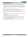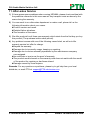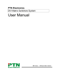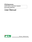
1
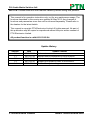
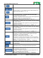
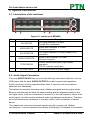
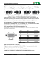
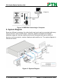
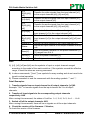
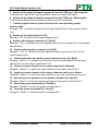
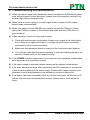
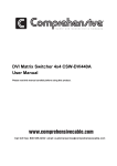
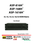
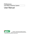
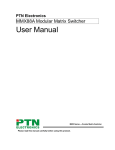
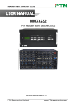
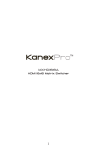
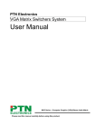
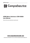
DVI /Audio Matrix Switcher 8x8 USER MANUAL MDV88A PTN DVI/Audio Matrix Switcher 8x8 Version: MDV88A2013V1.4 PTN Electronics Limited www.PTN-electronics.com DVI /Audio Matrix Switcher 8x8 NOTICE: Please read this user manual carefully before using this product. This manual is for operation instruction only, not for any maintenance usage. The functions described in this version are updated till May 2013. Any changes of functions and parameters since then will be informed separately. Please refer to the dealers for the latest details. This manual is copyright PTN Electronics Limited. All rights reserved. No part of this publication may be copied or reproduced without the prior written consent of PTN Electronics Limited. All product function is valid till 2013-05-24. Update History Version 1.0 1.1 1.2 1.3 1.4 Date 2013.01.04 2013.01.29 2013.02.27 2013.03.28 2013.05.24 PTN Electronics Limited Update Content First version. Modified some commands of EDID function. Added some introductions about the features. Updated the operation order of the buttons. Modified the system diagram. www.PTN-electronics.com DVI /Audio Matrix Switcher 8x8 Table of Contents 1. Introduction .............................................................................................................. 1 1.1. Introduction to MDV88A ................................................................................... 1 1.2. Package Contents ........................................................................................... 1 2. Features ................................................................................................................... 1 3. Specification ............................................................................................................. 2 4. Operations of the Front Panel and the IR Remote ................................................... 3 4.1. Operation of the Control Panel ........................................................................ 3 4.2. Usage of the IR Remote .................................................................................. 5 5. System Connection .................................................................................................. 6 5.1. Introduction of the Interfaces ........................................................................... 6 5.2. Audio Signal Connection ................................................................................. 6 5.3. Connection of RS232 Communication Port ..................................................... 7 5.4. Connection with Computer .............................................................................. 7 6. System Diagram....................................................................................................... 8 7. Advanced Function Introduction ............................................................................... 9 7.1. EDID Management Introduction....................................................................... 9 7.2. EDID management of MDV matrix................................................................... 9 7.2.1. RS232 Commands for EDID Management........................................... 9 7.2.2. EDID hand-shake priority ................................................................... 10 8. Communication Protocol and Command Codes .................................................... 10 9. Troubleshooting and Maintenance ......................................................................... 13 10. Safety Operation Guide .......................................................................................... 14 11. After-sales Service ................................................................................................. 15 PTN Electronics Limited www.PTN-electronics.com DVI /Audio Matrix Switcher 8x8 1. Introduction 1.1. Introduction to MDV88A MDV series Matrix switcher is a high-performance professional computer and audio signal switcher that can be used for cross switching of multi computer and audio signal. Independent DVI component and balance/unbalance I/O terminals make each component signal transmit and switch separately; this design can reduce attenuation of signal transmission to minimum and output the image and audio signal in high-fidelity quality. DVI series switcher mostly apply in broadcasting TV engineering, multi-media meeting room, big screen display engineering, television education, command control center or other fields. It supports A/V timing or separating switching function. With RS232 interface, it can be worked with PC, remote control system and any other far-end control system devices. 1.2. Package Contents 1 x MDV88A 1 x IR remote (Cell battery is not included) 1 x RS232 cable 16 x Captive screw connectors 4 x Plastic cushions 1 x Power Cord 1 x User Manual Notes:Please confirm if the product and the accessories are all included. If not, please contact with the dealers. 2. Features Support 3D &1080P, HDTV compatible. Stereo audio, each can switch separately. Controllable via buttons, RS232 & IR remote (Optional TCP/IP). Programmable through the RS232 serial port. Front panel security lock to avoid illegal operations. With the gain compensation technique and the synchronous signal correction technology, switching speed is less than 200ns (Max). With LED shows the operations taken. Easily control by using the IR remote. Internal switchable power (100Volt~240Volt AC, 50/60Hz) supply. Aluminum metal case, comply with the international standard height. PTN Electronics Limited 1 www.PTN-electronics.com DVI /Audio Matrix Switcher 8x8 3. Specification Video Input Input Input Connector Input Level Input Impedence Video General Gain Resolution Range Video Signal Switching Speed EDID and DDC Management HDCP Management Audio Input Input 8 DVI Female DB24+5 T.M.D.S. 2.9V/3.3V 50Ω 0 dB Upto1920 x 1200 or 1080P@60Hz, Support 3D DVI signal T.M.D.S signal Video Output Output Output Connector Output Level Output Impedence 8 DVI Female DB24+5 T.M.D.S. 2.9V/3.3V 50Ω Bandwidth 6.75 Gbit/s Max Time-delay 5nS (±1nS) Crosstalk <-50dB@5MHz 200ns (Max.) Supports Extended Display Identification Data (EDID) and Display Data Channel (DDC) data using DVI and HDMI standards, EDID and DDC signals are actively bufferred.The built-in EDID/DDC database can analyze these two signals, mix them, and realize the handshake of them internally. Compliant with High-bandwidth Digital Content Protection (HDCP) using DVI and HDMI 1.4a standards. The built-in HDCP management technology can analyze HDCP key, and realize the handshake internally. Audio Output 8 stereo, 8 stereo, Output balanced/unbalanced balanced/unbalanced Captive screw Output Captive screw connectors, 5 pole Connector connectors, 5 pole Output >10KΩ 50Ω Impedance Input Connector Input Impedance Audio General Frequency 20Hz ~ 20KHz Response Stereo Channel >80dB@1KHz Separation Control Parts PTN Electronics Limited CMRR >90dB@20Hz~20KHz THD + Noise 1%@1KHz, 0.3%@20KHz at nominal level 2 www.PTN-electronics.com DVI /Audio Matrix Switcher 8x8 Serial Control Port IR Remote Options General Power Supply Temperature Case Dimension RS-232, 9-pin female D connector Pin 2 = TX, 3 = RX, 5 = Configurations GND Front Panel Default IR remote Buttons Control TCP/IP control by PTNET(PTN's programmable interface) 100VAC ~ 240VAC, 50/60Hz -20 ~ +70℃ W483 x H87 x D320mm Power Consumption Humidity Product Weight 40W 10% ~ 90% 4.9Kg 4. Operations of the Front Panel and the IR Remote 4.1. Operation of the Control Panel ① ② ③ ④ Figure 4-1 Front Panel of MDV88A No. Name ① , IR ② INPUTS ③ OUTPUTS ④ MENU Description Power indicator, turn red when power on. IR is the infrared receiver. Input channel selection buttons, from 1 to 8. 8 channels in total. Output channel selection buttons, from 1to 8. 8 channels in total. Function buttons. Description of the buttons: Buttons Function Description Input buttons. It is the number of every input channel (8 in total), from left to right is 1, 2, 3…8. PTN Electronics Limited 3 www.PTN-electronics.com DVI /Audio Matrix Switcher 8x8 … … 8 8 Output buttons. It is the number of every output channel (8 in total), from left to right is 1, 2, 3…8. AV synchronal button: To transfer video and audio signal synchronously by the switcher. Example: To transfer both the video and the audio signals from input channel No.3 to output channel No.4. Operation: Press buttons in this order “3”, “AV”, “4””. Video button: To transfer only video signals from input channel to output channel Example: To transfer video signals from input channel No.3 to output channel No.4. Operation: Press buttons in this order “3”, “VIDEO”, “4”. Audio button: To transfer only audio signals from input channel to output channel Example: To transfer audio signals from input channel No.2 to output channel No.3. Operation: Press buttons in this order ““2”, “AUDIO”, “3””. All button: To transfer an input channel to all output channels. Example1: To transfer video and audio signals from input channel No.7 to all output channels. Operation: Press buttons in this order “7”, “ALL”. Example2: To transfer all input signals to the corresponding output channels respectively. In another word, to switch to this status: 1->1, 2->2, 3->3, 4->4……8->8. Operation: Press buttons in this order “ALL”, “THROUGH”. UNDO button: To resume to the status before the command just performed. Backspace button: To backspace the latest input button. Through button: To transfer the signals directly to the corresponding output channels. Example: To transfer the signals from input channel No. 3 to their corresponding output channels. Operation: Press buttons in this order “3”, “THROUGH”. PTN Electronics Limited 4 www.PTN-electronics.com DVI /Audio Matrix Switcher 8x8 Press the front panel buttons in this order: “Input Channel” +“Menu”+ “Output Channel” 1) “Input Channel”: Fill with the number of input channel to be controlled. 2) “Menu”: “AV”, “AUDIO”, “VIDEO”. 3) “Output Channel”: Fill with the number of output channels to be controlled. 4.2. Usage of the IR Remote With the infrared IR remote, the matrix switcher could be control remotely. As the function buttons on the IR remote are the same with the ones on the front control panel, the IR remote shares the same control operation and command format with the control panel. Operation order: “Input Channel” +“Menu”+ “Output Channel” The inputs channels, from 0~9, and plusing “10+” for more. Menu, for switching source and function The outputs channels, from 0~9, and plusing “10+” for more. Figure 4-2 Panel of the IR Remote PTN Electronics Limited 5 www.PTN-electronics.com DVI /Audio Matrix Switcher 8x8 5. System Connection 5.1. Introduction of the Interfaces ① ② ③ ④ Figure 5-1 Interfaces of MDV88A No. Name ① DVI INPUTS ② AUDIO INPUTS ③ DVI OUTPUTS ④ AUDIO OUTPUTS ⑤ TCP/IP/RS232 ⑥ AC100V~240V ⑤ ⑥ Description DVI input channels, 8 in total. Female DVI-I connector. Audio input channels, 8 in total. Phoenix connector. DVI output channels, 8 in total, female DVI-I connector. Audio output channels, 8 in total. Phoenix connector. RS232: Serial control port, 9-pin female connector. TCP/IP: network control port. Alternating current for power supply. 5.2. Audio Signal Connection The ports AUDIO INPUTS can be connected with any audio source devices, such as DVD player. And the ports AUDIO OUTPUTS can be connected with amplifiers. Audio connection is little complicated than video. It has two kinds of connection: balanced and unbalanced. The balanced connection transmits a pair of balanced signals with two signal cords. Because interferences will have the same intensity and the opposite phases on the two signal cords, it will be counteracted in the end. For the low frequency extent of the audio signal, it would be easily interfered under long distance transmission. Therefore, as an anti-interference connection, it is mostly used in audio connection of special device. The unbalanced connection transmits signals only with a signal cord. Without counteraction, it can be interfered more easily. Accordingly, it is adopted for household PTN Electronics Limited 6 www.PTN-electronics.com DVI /Audio Matrix Switcher 8x8 appliance or some cases with low technical demand. Take the audio signal line for example: 1.Unbalanced: pin “G” connect to SLEEVE, pin “+” connect to TIP, pin “–” connect to pin “G”; 2.Balanced: pin “G” connect to SLEEVE, pin “–” connect to RING, pin “+” connect to TIP. As shown in Figure 5-2: Tip Tip Sleeve Sleeves Tip Tip Sleeve Unbalanced Input Unbalanced Output Tip Ring Tip Ring Sleeves Tip Ring Sleeves Tip Ring Balanced Input Balanced Output Figure 5-2 5 bit 3.8mm Audio Balanced/unbalanced Connection Which connection to select is up to the interface of the device. When available, the balanced connection is the first choice. Before connection, please read the command or relevant demand in the user manual carefully. In some cases, maybe there is balanced in source signal end but unbalanced in the destination end. If in a nonstandard case, it is done to connect balanced for the balanced end and unbalanced for unbalanced end. But if in a standard one, the converter must be used to switch the signals as the same, balanced or unbalanced. 5.3. Connection of RS232 Communication Port This RS232 communication port is a female 9-pin D connector. The definition of its pins is as the table below. No. 1) 2) 3) 4) 5) 6) 7) 8) 9) Pin N/u Tx Rx N/u Gnd N/u N/u N/u N/u Function Unused Transmit Receive Unused Ground Unused Unused Unused Unused Figure 5-3 9HDF 5.4. Connection with Computer When the switcher connects to the COM1 or COM2 of the computer with control software, users can control it by that computer. To control the switcher, users may use the public COM software. Please refer the details in Communication Protocol and Command Codes. PTN Electronics Limited 7 www.PTN-electronics.com DVI /Audio Matrix Switcher 8x8 Figure 5-4 MDV88A Connecting to Computer 6. System Diagram Based on different occasions, the video/audio input ports can be connected with many source devices, such as DVD player, computer, graphic workstation and digital exhibition stage etc. And the output ports can be connected with various kinds of devices, such as projector, camera, displayer and amplifier etc. The system diagram is showed as below: Figure 6-1 System Diagram PTN Electronics Limited 8 www.PTN-electronics.com DVI /Audio Matrix Switcher 8x8 7. Advanced Function Introduction 7.1. EDID Management Introduction MDV matrix switcher is built in the EDID management database. The EDID management can be automatically shake hand, or manual exchanged, and factory restore. The MDV matrix switcher is built in the EDID data, which can communicate with the displayers and video source automatically. When the displayers or video sources are connected to the MDV matrix switcher, they will share the EDID/DDC information with the matrix switcher. The communication solution is like this: Figure 7-1 EDID Hand-shake Communication The MDV EDID database includes most popular displaying data, but not all the displaying data because of the capability and firmware limitation. So, we can manually refresh the EDID data to update the EDID data base. 7.2. EDID management of MDV matrix 7.2.1. RS232 Commands for EDID Management 1) The RS232 commands for EDID management of MDV matrix models include: ”EDIDMInit.” and”EDIDM[X]B[Y].”, dot in behind.) (Please notice the text-transform, and the When we send the “EDIDMInit.” to the MDV matrix switcher, it will recover the factory default EDID data. The feedback is “EDIDMInit”. When we send the RS232 command “EDIDM[X]B[Y].”. The matrix will copy the EDID data of output[X] to the input[Y]. The feedback is “EDIDM: [X]To[Y]”. 2) When a RS232 command is correctly sent, all the connected displayers will be PTN Electronics Limited 9 www.PTN-electronics.com DVI /Audio Matrix Switcher 8x8 blank for 3 seconds and recover again. And, the MDV matrix switcher will send out the RS232 feedback command. 3) If all these symbols works, it means the action is taken. 7.2.2. EDID hand-shake priority The EDID refresh ports have the priority grade, ranging from output 1 to output 8 in priority order. It means the output 1 is the most prior to exchange the EDID data, and then the output 2 is the second prior. And, the output 8 is the least prior. 8. Communication Protocol and Command Codes System Command Communication Protocol: RS232 Communication Protocol Baud rate: 9600 Data bit: 8 Stop bit: 1 Parity bit: none Command Command Functions Types Codes /*Type; Inquire the models information. /%Lock; Lock the keyboard of the control panel on the Matrix. /%Unlock; Unlock the keyboard of the control panel on the Matrix. /^Version; Inquire the version of firmware /:Message Turn off the feedback command from the com port. It Off; will only show the “SWITCH OK”. /:Message Turn on the feedback command from the com port. On; EDIDMInit. Recover the factory default EDID data EDIDM[X] Manually EDID switching. Copy the EDID data of B[Y]. output[X] to the input[Y]. Get the EDID data from the output port, and display the EDIDG[x] corresponding input port of output port x. Undo. To cancel the previous operation. Demo. Switch to demo mode, 1->1, 2->2, 3->3 … and so on. Transfer signals from the input channel [x1] to all [x1]All. output channels Transfer all input signals to the corresponding output All#. channels respectively. All$. Switch off all the output channels. Transfer signals from the input channel [x1] to the [x1]#. output channel [x1]. [x1]$. Switch off the output channel [x1]. Transfer the video signals from the input channel [x1] [x1] V[x2]. to the output channel [x2]. Operation Command (PTN2.0 Command System) PTN Electronics Limited 10 www.PTN-electronics.com DVI /Audio Matrix Switcher 8x8 [x1] V[x2],[x3],[ x4]. Transfer the video signals from the input channel [x1] to the output channels [x2], [x3] and [x4]. [x1] A[x2]. Transfer the audio signals from the input channel [x1] to the output channel [x2]. [x1] A[x2],[x3],[ x4]. Transfer the audio signals from the input channel [x1] to the output channels [x2], [x3] and [x4]. [x1] B[x2]. [x1] B[x2],[x3],[ x4]. Status[x1]. Status. Save[Y]. Transfer both the video and the audio signals from the input channel [x1] to the output channel [x2]. Transfer both the video and the audio signals from the input channel [x1] to the output channels [x2], [x3] and [x4]. Inquire the input channel to the output channel [x1]. Inquire the input channel to the output channels one by one. Save the present operation to the preset command [Y]. [Y] ranges from 0 to 9. Recall[Y]. Recall the preset command [Y]. Clear[Y]. Clear the preset command [Y]. Note: 1) [x1], [x2], [x3] and [x4] are the symbols of input or output channels ranged according to the model of the matrix switcher. If the symbols exceed the effective range, it would be taken as a wrong command. 2) In above commands, “[”and “]” are symbols for easy reading and do not need to be typed in actual operation. 3) Please remember to end the commands with the ending symbols “.” and “;”. Detail Examples: 1. Transfer signals from an input channel to all output channels: [x1]All. Example: “3All.” to transfer signals from the input channel No.3 to all output channels. 2. Transfer all input signals to the corresponding output channels respectively: All#. After running this command, the status of it will be: 1->1, 2->2, 3->3, 4->4……8->8. 3. Switch off all the output channels: All$. After running this command, there will be no signals on all the output channels. 4. Check the version of the firmware: /^Version; To check the version of the firmware. PTN Electronics Limited 11 www.PTN-electronics.com DVI /Audio Matrix Switcher 8x8 5. Switch off the detail feedback command from the COM port: /:MessageOff; It will leave the “switch OK” as the feedback, when you switch the matrix. 6. Switch on the detail feedback command from the COM port: /:MessageOn; It will show the detail switch information when send the commands. 7. Transfer signals from an input channel to the corresponding output channel: [x]#. Example: “5#.” to transfer signals from the input channel No.5 to the output channel No.5. 8、Switch off an output channel: [x]$. Example: “5$.” to switch off the output channel No.5. 9、Switch video signals command: [x1] V[x2]. Example: “3V5.” to transfer the video signals from the input channel No.3 to the output channel No.5. 10. Switch audio signals command: [x1] A[x2]. Example: “1A2.” to Transfer the audio signals from the input channel No.1 to the output channel No.2. 11. Switch both video and audio signals synchronously: [x1] B[x2]. Example: “8B2,3,5.” to transfer both the video and the audio signals from the input channel No.8 to the output channel No.2,3,5. 12. Inquire the input channel to the output channel [x]: Status[x]. Example: “Status3.” to inquire the input channel to the output channel No.3. 13. Inquire the input channel to the output channels one by one: Status. Example: “Status.” to inquire the input channel to the output channels one by one. 14. Save the present operation to the preset command [Y]: Save[Y]. Example: “Save7.” to save the present operation to the preset command No.7. 15. Recall the preset command [Y]: Recall[Y]. Example: “Recall5.” to recall the preset command No.5. 16. Clear the preset command [Y]: Clear[Y]. Example: “Clear5.” to clear the preset command No.5. PTN Electronics Limited 12 www.PTN-electronics.com DVI /Audio Matrix Switcher 8x8 9. Troubleshooting and Maintenance 1) When the output image in the destination device connected to MDV88A has ghost, such as the projector output with ghost, please check the projector’s setting or try another high quality connection cord. 2) When there is a color losing or no video signal output, maybe the DVI cables haven’t been connected well. 3) When user cannot control MDV88A by computer through its COM port, please check the COM port number in the software and make sure the COM port is in good condition. 4) When switching , there is no any output image: A. Check with oscilloscope or multimeter if there is any signal at the input/output end. If there is no signal input/output, it may be the input/output connection cord broken or the connectors loosen. B. Make sure the destination device is exactly on the controlled output channel. C. If it is still the same after the above checking, it may be something wrong in the switcher. Please send it to the dealer for fixing. 5) If the POWER indicator doesn’t work or no respond to any operation, please make sure the power cord connection is good. 6) If the output image is interfered, please make sure the system is earthed well. 7) If the static becomes stronger when connecting the DVI connectors, it may be due to the incorrect earthling of the power supply, Please earth it again correctly, and otherwise it would bring damage to the switcher or shorten its natural life. 8) If the Matrix cannot be controlled by the keys on the front panel, RS232 port or IR remote, the host may has already been broken. Please send it to the dealer for fixing. PTN Electronics Limited 13 www.PTN-electronics.com DVI /Audio Matrix Switcher 8x8 10. Safety Operation Guide In order to guarantee the reliable operation of the equipments and safety of the staff, please abide by the following proceeding in installation, using and maintenance: 1) The system must be earthed properly. Please do not use two blades plugs and ensure the alternating power supply ranged from 100v to 240v and from 50Hz to 60Hz. 2) Do not put the switcher in a place of too hot or too cold. 3) As the power generating heat when running, the working environment should be maintained fine ventilation, in case of damage caused by overheat. 4) Please cut off the general power switch in humid weather or left unused for long time. 5) Before following operation, ensure that the alternating current wire is pull out of the power supply: Take off or reship any components of the equipment. Take off or rejoin any pin or other link of the equipment. 6) As to non-professional or without permission, please DO NOT try to open the casing of the equipment, DO NOT repair it on your own, in case of accident or increasing the damage of the equipment. 7) DO NOT splash any chemistry substance or liquid in the equipment or around. PTN Electronics Limited 14 www.PTN-electronics.com DVI /Audio Matrix Switcher 8x8 11. After-sales Service 1) If there appear some problems when running MDV88A, please check and deal with the problems reference to this user manual. Any transport costs are borne by the users during the warranty. 2) You can email to our after-sales department or make a call, please tell us the following information about your cases. Product version and name. Detailed failure situations. The formation of the cases. 3) We offer products for all three-year warranty, which starts from the first day you buy this product (The purchase invoice shall prevail). 4) Any problem is same with one of the following cases listed, we will not offer warranty service but offer for charge. Beyond the warranty. Damage due to incorrectly usage, keeping or repairing. Damage due to device assembly operations by the maintenance company non-assigned. No certificate or invoice as the proof of warranty. The product model showed on the warranty card does not match with the model of the product for repairing or had been altered. Damage caused by force majeure. Remarks: For any questions or problems, please try to get help from your local distributor, or email PTN at: [email protected]. PTN Electronics Limited 15 www.PTN-electronics.com