1
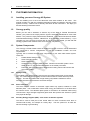
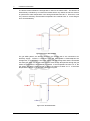
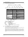
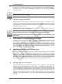
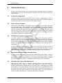
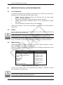
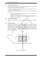
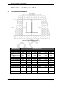
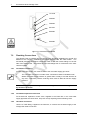
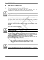
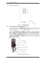
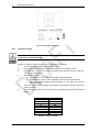
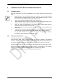
CONERGY PTY LTD Conergy AS Owner & Installation Manual Table of Contents 1 Customer Information ................................................................................................................ 2 1.1 Installing your new Conergy AS System .......................................................................... 2 1.2 Conergy quality ................................................................................................................. 2 1.3 System Components ........................................................................................................ 2 1.4 Conergy model numbers explained .................................................................................. 4 1.5 Is the system suitable for extremely cold climates? ......................................................... 4 1.6 Important safety information ............................................................................................. 5 1.7 If the customer is away for a long period of time .............................................................. 5 1.8 Water discharge through the pressure valve .................................................................... 5 1.9 Hydrogen gas can accumulate! ........................................................................................ 5 2 Troubleshooting ......................................................................................................................... 6 2.1 Low solar energy input ..................................................................................................... 6 2.2 Solar collector shading ..................................................................................................... 6 2.3 AES (Booster) system not operating ................................................................................ 6 2.4 Excessive water discharge from the valves ..................................................................... 6 2.5 Hot water use higher than anticipated .............................................................................. 6 2.6 Water discharge from the frost valve ................................................................................ 7 3 System Maintenance ................................................................................................................. 8 3.1 Draining and flushing the system ..................................................................................... 8 3.2 Collector glass cleaning .................................................................................................... 8 3.3 Hail damage or broken collector glass ............................................................................. 8 3.4 Relief valves ..................................................................................................................... 9 4 Important Installation Information ............................................................................................ 10 4.1 Local Standards .............................................................................................................. 10 4.2 Safety .............................................................................................................................. 10 4.3 Water Quality .................................................................................................................. 10 4.4 Pressure Reducing Valve ............................................................................................... 11 4.5 High wind or cyclonic areas ............................................................................................ 11 4.6 Piping material ................................................................................................................ 11 4.7 Supplementary heat sources .......................................................................................... 11 4.8 Legionella requirements ................................................................................................. 12 4.9 Roof location selection ................................................................................................... 12 5 Dimensions and Technical Data ............................................................................................. 14 5.1 Collector Installation Area ............................................................................................... 14 5.2 Parts Kit Details .............................................................................................................. 15 5.3 System Weights .............................................................................................................. 16 6 Installation Instructions ............................................................................................................ 17 6.1 Installing the collectors ................................................................................................... 17 6.2 Flat roof installations ....................................................................................................... 19 6.3 Solar Flow and Return Lines .......................................................................................... 19 7 Connections at the Storage Tank ............................................................................................ 21 7.1 Connections for the PM-600 ........................................................................................... 21 7.2 Plumbing Connections .................................................................................................... 22 8 Electrical Connections ............................................................................................................. 23 8.1 Electrical connection for Electric AES (Booster) ............................................................ 23 8.2 Electrical Installation for the PM-600 .............................................................................. 24 8.3 Gas AES installation instructions .................................................................................... 26 9 Commissioning & Customer Hand Over ................................................................................. 27 9.1 Commissioning ............................................................................................................... 27 9.2 Customer Hand Over ...................................................................................................... 27 10 Warranty .................................................................................................................................. 28 11 Contact Details ........................................................................................................................ 28 Envirosun AS Installation Manual Rev1a PVNW.docx Page 1 1 Customer Information 1 CUSTOMER INFORMATION 1.1 Installing your new Conergy AS System You are installing one of the most advanced solar water heaters in the world. This manual provides you with the essential information needed to install the Conergy Active System correctly. Please read it carefully and follow all the instructions. We hope you find the following information useful. 1.2 Conergy quality Before you can sell in Australia, or achieve any of the State or Federal Government rebates, your product must comply with the rigorous Australian Standards for solar water heaters. Our products comply with all these standards. The Federal Government Smallscale Renewable Energy Scheme, called STCs, is an indication of solar efficiency. If you compare any of the Conergy products with an equal competitor model, you will find that Conergy systems often achieve more STCs than our competitors. 1.3 System Components The Conergy AS Solar Water Heater is supplied in kit form so that it can be assembled and connected in various configurations to suit the installation location and user requirements. Typically, the kit contains the five main components of your solar water heater system. These are: 1. Potable Water Storage Tank; 2. Solar Controller Module; 3. Solar Collector (s); 4. Ancillary Energy Support (AES) System. Please note the AES system can be either electric or gas operated dependent on the model purchased; 5. Parts Box, which includes pipes, fittings and mounting rails to interconnect and mount the system. 1.3.1 Storage Tank The potable water storage tank is used to store the heated water ready for household use. It is constructed of high quality vitreous enamel lined low carbon steel to provide long life. The tank is insulated with a high density polyurethane material to ensure minimal heat losses and maximum structural strength. 1.3.2 Solar Collectors The solar collector contains a multi-tube copper water way system, bonded to a solar absorber plate. This combination collects solar energy and transfers it to the fluid within the collector circuit. The absorber plate system is enclosed in an insulated metal casing covered with a high strength toughened glass sheet that protects the absorber system from physical damage. 1.3.3 Ancillary Energy Support (AES) - also known as booster systems The AES is used to heat part of the stored water on those occasions when there is reduced solar activity, for example on cloudy days. The two options for an AES are electric boosting or gas boosting. Envirosun AS Installation Manual Rev1a PVNW.docx Page 2 1 Customer Information The electric element within the storage tank is used for the electric AES. This element is automatically controlled by an internal thermostat which only allows the electric element to operate if the water temperature in the storage tank falls below 60 °C. Even then, it will only consume electricity until the water temperature is increased to 60 °C. At this stage it turns off automatically. Figure 1.3.1 Electric AES Schematic For gas AES systems, the electric element in the storage tank is not connected to an electricity supply. Instead, a continuous flow gas water heater is fitted adjacent the storage tank, in series with the hot water supply from the storage tank and the household hot water pipe work. As the hot water from the solar storage tank passes through the gas heater its temperature is automatically monitored. If the temperature is below 70 °C, the gas heater will add the heat required to deliver hot water of at least 70 °C. If the water temperature is above 70 °C, the gas heater will not ignite. Figure 1.3.2: Gas AES Schematic Envirosun AS Installation Manual Rev1a PVNW.docx Page 3 1 Customer Information 1.4 Conergy model numbers explained XX NNN / XX / X / XNN / X / XNNXX System Type – Nom. Volume – Collector Area – Tank Type – Booster – Tank Material – Collector Variable Categories System Type AS Active Systems (pumped) HP Heat Pump System Type TS Thermosiphon, TS Nominal Volume Nominal Storage Volume Collector Area 20, 25, 40, 50, 60 Tank Type Booster Tank Material / Designation Collector Type 2 Nominal Collector Area (m x10) O Open Circuit C Closed Circuit E Electric G Gas XX Booster Rating (kWx10 or Lpm) V Vitreous Enamel S Stainless Steel E20BC, E25BC or E20AA Table 1.4.1 System Model Number For example, AS315/40/0/E36/V/E20AA: AS 315 40 E36 V E20AA 1.5 = = = = = = Active System; 315 litre storage tank; 4 m² of collector area; an electric AES with 3.6 kW rating; Vitreous enamel tank; 2 m² selective surface solar collector, model E20AA. Is the system suitable for extremely cold climates? The open circuit system is not suitable for frost prone or freeze areas. If you are in a frost prone or freeze area you must install a closed circuit system. Whilst frost valves may be used to protect from mild damage of frosts to collectors, installing a frost valve will not guarantee against frost damage. Damaged sustained to the system in the event of freezing is not covered under warranty. Only closed circuit AS models are warranted against freezing. See separate instructions and guidance on these models. Envirosun AS Installation Manual Rev1a PVNW.docx Page 4 1 Customer Information If the unit is to be fitted in areas prone to frost and freezing the unit must be installed in accordance with any relevant sustainability programme (such as the Sustainability Victoria program). A breach of this requirement may void the warranty in the event of damage caused by leaking due to frost or freezing. 1.6 Important safety information All water heaters have the ability to produce hot water very quickly. To reduce the risk of scald injury it is recommended that a temperature control valve be fitted to the hot water supply pipe work. This valve should be checked every 6 months to ensure its operation and settings remain correct. Check that the pressure & temperature relief valve drain pipe is not located where it can cause damage if hot water is discharged. This water heater is not intended for use by young children, infirm persons, or persons lacking relevant skill or experience, without suitable supervision. Children should be supervised to ensure they do not play with hot water taps or the water heater. 1.7 If the customer is away for a long period of time If the system is not to be used for a period of a week or more during the summer months it is advisable to turn off the electricity supply to the booster and if practical, cover the solar collectors. If the solar collectors are not covered there is a possibility that the high temperature valve in the storage tank may open and disperse small amounts of hot water for a short period to reduce the storage tank temperature while you are away. This is a normal function and does not harm the system. 1.8 Water discharge through the pressure valve All Conergy solar water heaters have two pressure valves located within the system configuration. The cold water expansion control valve (ECV), located in the cold water supply pipe, may release a small amount of water from time to time during the heating cycle of the system. The water discharge is water expanding due to the heating process. Normally the discharge will be less than 10 litres per day. The pressure & temperature valve, located on the storage tank, may also release a small expansion discharge. 1.9 Hydrogen gas can accumulate! If the hot water system is not used for two weeks or more, a quantity of highly flammable hydrogen gas may accumulate in the water heater. To dissipate this gas safely, it is recommended that a hot tap be turned on for several minutes at a sink, basin or bath. Do not use a dishwasher, clothes washer or other appliance. During this procedure there must be no smoking, open flame or any other electrical appliance operating nearby. If hydrogen is discharged through the tap, it will probably make an unusual noise as with air escaping. Do not place hands or any part of your body beneath the tap during this procedure. Envirosun AS Installation Manual Rev1a PVNW.docx Page 5 2 Troubleshooting 2 TROUBLESHOOTING If there is not enough hot water we recommend that the following points are considered as part of the service call. The most obvious reasons for a lack of hot water could be one of the following. 2.1 Low solar energy input If there have been prolonged periods of cloud or winter is approaching, it may be necessary to reconsider the permitted boosting time for time-clock controlled systems or to turn on the booster for systems with a booster isolation switch. 2.2 Solar collector shading Often trees or other buildings can shade the solar collectors or there can be a dirt buildup on the glass cover. Trees should be cut back if possible or the system relocated if removal of the shading is not possible in the present location. If the glass is dirty this should be cleaned with standard domestic glass cleaner. If rainwater collection occurs from the same roof on which the solar water heater is located, do not use chemical cleaning agents to clean the collectors. Any spillage of these onto the roof could cause contamination of water in the rainwater tank. 2.3 AES (Booster) system not operating For electric systems the fuse or circuit breaker supplying the AES System should be checked. If the time clock (where fitted) and the fuse or circuit breaker are operational and the water is cold, you can turn the booster isolator on and off to see if the electricity meter speed changes. If there is no change in speed, it indicates there may be a booster problem. Contact your authorised Conergy dealer or installation service provider as soon as possible. For gas systems the gas and electric supplies to the gas heater should be checked to ensure they are both on. If water temperature from the gas heater is below 70 °C and both supplies are on and the gas heater does not ignite there may be a problem. Contact your authorised Conergy dealer or installation service provider as soon as possible. 2.4 Excessive water discharge from the valves It is normal for the Expansion Control Valve (ECV) to drip water when heating. If there is a discharge of more than 10 litres per day from any of the systems valves, it indicates there may be a problem with the valve or an increased water supply pressure. Contact your authorised Conergy dealer or installation service provider as soon as possible. 2.5 Hot water use higher than anticipated Often the hot water usage of showers, washing machines and dishwashers is underestimated by the customer. Review these appliances to determine if the daily usage is greater than the storage volume of the water heater. Depending on the model and conditions, our AS system tanks contain 250 to 400 litres of hot water therefore if the hot water load is greater than the system capacity within a short period of time, there may be periods where the water temperature is lower than normal. It is also advisable to inspect hot water tap washers etc. for leakage and replace if necessary. Envirosun AS Installation Manual Rev1a PVNW.docx Page 6 2 Troubleshooting 2.6 Water discharge from the frost valve If your system has a frost valve fitted it will be located at the bottom corner of the collector. In temperatures that cause frost or freezing the valve will open and some water will discharge from this valve. There is nothing that needs to be done to the valve or the system, it is operating correctly. The water will stop discharging once the valve has warmed enough to close again, usually as the frost clears. Refer to section 1.5 on page 4 for more information on frost protection. Envirosun AS Installation Manual Rev1a PVNW.docx Page 7 3 System Maintenance 3 SYSTEM MAINTENANCE The Conergy solar water heater is designed so that there is little to do in the way of system maintenance. Personally inspecting or servicing any part of the system is not recommended. Should you decide that you want to inspect the roof mounted collectors, it is essential that you use all safety devices required to ensure your personal safety. Most importantly the electricity supply must be turned OFF. 3.1 Draining and flushing the system The system must be completely drained of water before any plumbing work is commenced. This will prevent damage to the storage tank in the event of a vacuum or excessive pressure forming at the storage tank. The Conergy AS hot water system should be drained and flushed every five years during a major service of the unit. 1. 2. 3. 4. 5. 6. 7. 3.2 Turn off and isolate the power supply to the electrical element. Turn off the water supply to the water heater. Release excess pressure from the tank by manually opening the pressure & temperature relief valve. Disconnect the cold water supply pipe connection to the tank. Fit a ½” flexible drain pipe to the cold connection at the tank. Place the open end of the drain hose in a location where it is safe for the hot water to drain away from the tank. Manually open the pressure & temperature relief valve which will allow air into the tank and the water within the tank will flow out via the flexible drain pipe fitted to the cold inlet connection. Hold the valve open until the tank is empty. To drain the collectors, disconnect the cold pipe from the bottom of the collector array. Collector glass cleaning Glass cleaning usually occurs by natural rainfall, however if the installation is in an industrial (or similar) area with high levels of airborne particles then a qualified person can clean the collector glass with normal window cleaning chemicals and equipment. If rainwater collection occurs from the same roof on which the solar water heater is located, do not use chemical cleaning agents to clean the collectors. Any spillage of these onto the roof could cause contamination of water in the rainwater tank. 3.3 Hail damage or broken collector glass In the unusual case that the toughened glass collector covers are broken, Conergy does not advise replacement of the glass. The entire panel should be replaced to maintain the performance and integrity of the water heater. Replacement panels should be installed by a qualified person. Envirosun AS Installation Manual Rev1a PVNW.docx Page 8 3 System Maintenance 3.4 Relief valves The lever on the relief valves should be operated at least every six months. Failure to do so may result in failure of the tank. If water does not discharge freely from the valves they should be checked and possibly replaced. The relief valves and relief valve drain lines must not be blocked. Some water may discharge during each heating cycle Every five year’s all safety valves should be replaced to ensure continued life and operational safety of the system. In locations where the potable water has a Total Dissolved Solids (TDS) of greater than 600 ppm it is recommended to replace all safety valves every 3 years. Envirosun AS Installation Manual Rev1a PVNW.docx Page 9 4 Important Installation Information 4 IMPORTANT INSTALLATION INFORMATION 4.1 Local Standards The following standards and regulations must be taken into account when planning the installation of the Conergy AS solar water heater system. AS/NZS 3500.4.2 National plumbing and drainage code hot water supply systems – acceptable solutions. HB 263-2004 heated water systems plumbing industry commission. AS/NZS 3000 Electrical installations (known as the Australian/New Zealand wiring rules). Any local regulations that govern this type of installation. Where these instructions and any local regulations are in conflict, the local regulations shall prevail. 4.2 Safety Do not commence any aspect of this installation until you have satisfied yourself that all safety issues have been addressed. This installation should only be performed by an approved professional with suitable experience and licenses, authorised by Conergy to conduct the work. It is imperative that installers adhere to Occupational Health and Safety Guidelines at all times. The installer is responsible for their safety and the safety of those around them. 4.3 Water Quality Water supply from an unfiltered water source that may be highly conductive or have a high mineral content may void the system warranty. Therefore, to ensure water quality guidelines are met, the following characteristics should not be exceeded. Water Properties Acceptable Levels Total hardness 200 mg/litre or ppm Total Dissolved Solids (TDS) 600 mg/litre or ppm Chloride 250 mg/litre or ppm Magnesium 10 mg/litre or ppm Sodium 150 mg/litre or ppm pH Min 6.5 to Max 8.5 Electrical conductivity 850 μS/cm Table 4.3.1 Water quality requirements In areas of poor water quality, it is recommended that a softener, conditioner or similar device be fitted to the water supply. A breach of this condition may void the warranty in the event of damage caused by water quality exceeding these characteristics. Envirosun AS Installation Manual Rev1a PVNW.docx Page 10 4 Important Installation Information 4.4 Pressure Reducing Valve Where the mains water supply pressure is likely to exceed 550 kPa at any time, a 500kPa pressure reducing valve that complies with AS1357 must be fitted to the inlet of the hot water system. This is essential to safeguard the appliance and ensure correct operation. A breach of this requirement may void the warranty in the event of damage caused by excessive pressure. 4.5 High wind or cyclonic areas The standard mounting system is sufficient for mounting most standard roof installations of either metal or tile roof construction. It may be necessary to use the cyclone mounting system if one of the following applies: The collector must be installed 1m (recommended) to 0.5m (minimum) of a roof edge or peak. The installation has minimal shielding from surrounding buildings and trees, or is located on a hill or similar locations that may cause high wind effects (refer to Terrain Categories, Topographic Effects & Shielding Factors in AS 1170.2: 2002, or consult a structural engineer). The installation is on a roof with a pitch greater than 30°. If the solar water heater is installed in an area classed as Cyclone Region C or D according to AS 1170.2: 2002, the standard mounting systems must not be used. Please consult a structural engineer for advice on ensuring the installation will comply with local building codes and regulations. 4.6 Piping material Conergy recommends the use of copper pipe, certified to AS1432 Class C, for use in the flow and return lines to the solar water system. Plastic piping is not to be used for any portion of the water heater system plumbing unless the pipe manufacturer has rated it for temperatures up to 99°C and a minimum water pressure of 600kPa at these temperatures. 4.7 Supplementary heat sources If a supplementary heat source is connected to the storage tank, the maximum energy input cannot be more than 10 kW, including the electrical element. Where greater input is required, a pressure and temperature relief valve with a higher kW rating is to be fitted to the storage tank. Where stove coils are used for supplementary heating the water must be connected in an open vented manner. Refer to Australian Standard AS3500 for more details on acceptable connection solutions. Any supplementary heat source must be limited such that the maximum tank temperature is 80 °C. Envirosun AS Installation Manual Rev1a PVNW.docx Page 11 4 Important Installation Information 4.8 Legionella requirements The Australian Standards require that a water heater system provide a means to inhibit the growth of the Legionella bacteria in potable water. If the system is installed with an approved Gas AES, with the outlet temperature set to 70°C, then this requirement is satisfied. If the system is installed with an Electric AES, then one of the following requirements must be met: 1. 2. 4.9 At least 45% of the storage volume is heated to 60°C daily. This can be achieved by leaving the AES permanently on. At least 90% of the storage volume is heated to 60°C for 32 minutes in each 7 day period. This will require any timing device or manual control to be adequately set-up or operated. Roof location selection There are six major factors to consider when selecting the solar collector installation location: 4.9.1 Collector orientation For optimum performance, the solar collectors need to face the equator (in southern hemisphere this is north and in the northern hemisphere this is south). Installations orientated at angles of up to 45° away from the equator do not have a major effect on the annual solar output. Consequently, roof locations which face less than 45° away from the equator are acceptable. If the collectors are installed with an east facing bias the best solar input is achieved in the morning and if there is a west facing bias the best solar input is in the afternoon. Figure 4.9.1 Collector orientation Envirosun AS Installation Manual Rev1a PVNW.docx Page 12 4 Important Installation Information 4.9.2 Shading Careful site inspection is required to ensure the selected location is not subjected to shading from adjacent trees or buildings throughout the day, but particularly between 9am and 3pm, the highest solar input times. Shadows are longer in winter than in summer so a site that is free of shadows from adjacent objects in summer may have some shadows in winter. 4.9.3 Storage tank location The solar water heater should be located as close as possible to the location which uses the most hot water e.g. the bathroom or kitchen. This is to reduce energy losses which may occur if the pipe work between the solar water heater and the point of usage is too long. 4.9.4 Collector inclination To achieve optimum performance the solar water heater should be installed on a roof pitch of greater than 10° and less than 30°. Installations on a roof where the roof pitch is greater than 30° will require additional support at the storage tank to prevent it moving downward during and after installation. If the roof pitch is less than 10°, the system will require a mounting frame to increase the pitch above 10°. Air can accumulate in installations below 10° and may not circulate effectively. Additionally the collector glass will not self-clean during rainy periods. 4.9.5 Roof structure Ensure the roofing material and roof structure is capable of supporting the full load of the collectors and trades personnel during installation. The structure should be capable of supporting a 250kg point load. If this is not the case, additional bracing must be installed before proceeding with the installation. The Conergy AS hot water system can be installed on metal or tile roofs. 4.9.6 Roof area To ensure adequate working access for the installation and future maintenance, an area of not less than 500mm should be left completely around the system. The system should be located 1m from all roof edges and peaks, with a minimum distance of 0.5m. Sufficient distance must be allowed up the roof from the storage tank for securing the mounting straps. Envirosun AS Installation Manual Rev1a PVNW.docx Page 13 5 Dimensions and Technical Data 5 DIMENSIONS AND TECHNICAL DATA 5.1 Collector Installation Area Figure 5.1.1 Collector Installation Area Model Number Dimensions (mm) A B C D E F TS180/20/C///E20 2600 1370 1226 2000 1000 82 TS180/20/O///E20 2600 1370 1226 2000 1000 82 TS180/25/C///E25 2600 1370 1226 2000 1235 82 TS180/25/O///E25 2600 1370 1226 2000 1235 82 TS300/25/C///E25 2600 1370 2010 2000 1235 82 TS300/25/O///E25 2600 1370 2010 2000 1235 82 TS300/40/C///E20 2600 2238 2010 2000 1000 82 TS300/40/O///E20 2600 2238 2010 2000 1000 82 TS300/50/C///E25 2600 2645 2010 2000 1235 82 TS300/50/O///E25 2600 2645 2010 2000 1235 82 TS300/60/C///E20 2600 3260 2010 2000 1000 82 TS300/60/O///E20 2600 3260 2010 2000 1000 82 Table 5.1.1 System dimensions Envirosun AS Installation Manual Rev1a PVNW.docx Page 14 5 Dimensions and Technical Data 5.2 Parts Kit Details Model Number Tank Collector Connection Kit Mounting Kit TS180/20/C///E20 TS180/C/E24 E20BC PK-2101 PK-1204 TS180/20/O///E20 TS180/O/E24 E20BC PK-2100 PK-1204 TS180/25/C///E25 TS180/C/E24 E25BC PK-2101 PK-1204 TS180/25/O///E25 TS180/O/E24 E25BC PK-2100 PK-1204 TS300/25/C///E25 TS300/C/E24 E25BC PK-2101 PK-1204 TS300/25/O///E25 TS300/O/E24 E25BC PK-2100 PK-1204 TS300/40/C///E20 TS300/C/E24 E20BC PK-2103 PK-1205 TS300/40/O///E20 TS300/O/E24 E20BC PK-2102 PK-1205 TS300/50/C///E25 TS300/C/E24 E25BC PK-2101 PK-1206 TS300/50/O///E25 TS300/O/E24 E25BC PK-2100 PK-1206 TS300/60/C///E20 TS300/C/E24 E20BC PK-2103 PK-2104 PK-1205 PK-1207 TS300/60/O///E20 TS300/O/E24 E20BC PK-2102 PK2104 PK-1205 PK-1207 Table 5.2.1 Details of System Parts Kits Before starting the installation, please check carefully to ensure all items are accounted for. Envirosun AS Installation Manual Rev1a PVNW.docx Page 15 5 Dimensions and Technical Data 5.3 System Weights Tank Material Weight – Empty (kg) Weight – Full (kg) TS180/C/E24/V Vitreous Enamel Mild Steel 64 239 TS180/O/E24/V Vitreous Enamel Mild Steel 54 229 TS300/C/E24/V Vitreous Enamel Mild Steel 101 399 TS300/O/E24/V Vitreous Enamel Mild Steel 87 385 TS300/O/E24/S 444 Stainless Steel 71 369 Table 5.3.1 TS Tank Weights Collector Weight – Empty (kg) Weight – Full (kg) E20BC 29.5 31.2 E25BC 36.0 38.0 E20AA 39.0 40.7 Table 5.3.2 Collector Weights Envirosun AS Installation Manual Rev1a PVNW.docx Page 16 6 Installation Instructions 6 INSTALLATION INSTRUCTIONS Before commencing the installation of the solar water heater system, please ensure you have familiarised yourself with the requirements of Section 4 Important Installation Information. Remove all packaging and protective coatings and dispose of them in an appropriate manner. This includes the plastic core-strip from the back of the collector and the plugs from the collector and storage tank connection pipes. 6.1 Installing the collectors Figure 6.1.1 Collector Installation General Assembly 1. 2. 3. 4. 5. Mark a point for the bottom left corner of the collector installation. This point should be at least 500 mm up from the roof edge and 500 mm to the side of any obstruction or roof edge. Place one end of the collector mounting rail (Error! Reference source not found., ) adjacent the location marked in step 1, and laid horizontally across the roof to the right. Locate two roof trusses which are under the collector mounting rail (as near as possible to the outer edges of the rail). Clip two collector straps (Detail E - item 16) to the collector mounting rail where the trusses pass under the mounting rail. Adjust the mounting rail so that it is 15 – 20 mm higher (up the roof) on the right side, then screw fix the collector straps to the roof trusses using the pre-punched holes. Take the first solar collector and place it on the collector mounting rail, at the leftmost end. For a single collector installation, go directly to step 8. 6. 7. Loosely fit the two collector connectors (Detail B, Item 3) to the two copper tube spigots on the right side of collector. Take the second collector and place it onto the right hand side of the collector mounting rail. Now, slide collector toward the first collector until the two copper Envirosun AS Installation Manual Rev1a PVNW.docx Page 17 6 Installation Instructions 8. 9. 10. 11. 12. 13. 14. 15. 16. 17. 18. 19. 20. tube spigots of that collector slide fully home into the collector connectors already fitted to collector. Tighten the compression nuts of the collector connector fittings (Detail B – item 3), taking care not to twist the copper tubes of the collector. Make sure you use correctly sized spanners and that the centre nut is held steady whilst the compressing nuts are tightened. Move the collectors so that they are centrally located on the collector mounting rail. Screw fix the collector rail to the collector/s using the screws supplied. (Detail E - item 19) To fix the top of the collectors to the roof, take the remaining mounting straps (Detail G, item 16) and place as centrally as possible at the top of each of the collectors with the strap fixing ends pointing up the roof. Screw fix the collector straps to the collector Figure 6.1.2 Detail A using the screws supplied. (Detail E - item 19) Finally, screw fix the collector straps to the roof rafters to complete the collector mounting. Steps 14 to 19 relate only to the 3 Panel Array: Loosely fit the two collector connectors (Detail B, Item 3) to the two copper tube spigots on the right side of the second collector. Locate a roof truss which is under the third panel extension rail (detail XX – itemXX), as near as possible to the outer edge of the rail. Clip one collector strap (Detail E - item 16) to the extension rail where the truss will pass Figure 6.1.3 Detail B under the extension rail. Screw fix the extension rail to the two panel collector rail that is already installed, using the self-drilling screws supplied (Detail E - Item 19) The extension rail is provided with grooves and pilot holes for correct positioning. Take the third collector and place it onto the right hand side of the extension rail. Slide the collector toward the second collector until the two copper tube spigots of that collector slide fully home into the collector connectors. Figure 6.1.4 Detail C Tighten the compression nuts of the collector connector fittings (Detail B – item 3) taking care not to twist the copper tubes of the collector. Make sure you use correctly sized spanners and that the centre nut is held steady whilst the compressing nuts are tightened. Slide a Compression Plug assembly (Detail D, item 4) to the top left and bottom right corners of the array. Tighten the assembly taking care not to twist the copper tubes of the collector. Make sure you use correctly sized spanners and that the nut is held steady whilst the Figure 6.1.5 Detail D compressing plug is tightened. Envirosun AS Installation Manual Rev1a PVNW.docx Page 18 6 Installation Instructions 21. 22. 23. 24. 25. 26. 27. 28. Assemble and install the Hot Connection Union assembly (Detail A) as follows; Take the temperature well (Detail A – item 10) and slide it onto the copper spigot at the top right of the collector array. Tighten the assembly taking care not to twist the copper tubes of the collector. Make sure you use correctly sized spanners and that the nut is held steady whilst the compressing plug is tightened. Wind five turns of thread tape onto the ½” BSP thread of the Temperature Well Insert the Temperature Well into the ½” BSP socket end of the Hot Connection Union (Detail A – item9) and tighten normally. Take care not to over tighten. Wind five turns of thread tape onto the ⅜” BSP thread of the Air Bleed Valve. Screw fit the Air Bleed Valve (Detail A – item 8) into the top ⅜” BSP socket and tighten Open the Air Bleed Valve by turning the knob on top anti-clockwise 1 ½ turns from closed. Slide the ¾” BSP Compression Union Assembly (Detail D, item 4) to the bottom left hand corner connection of the array. Tighten the assembly taking care not to twist the copper tubes of the collector. Make sure you use correctly sized spanners and that the nut is held steady whilst the compressing union is tightened. Figure 6.1.6 Detail E Figure 6.1.7 Detail F The collector array is now completed and ready for connection to the water heater system. Figure 6.1.8 Detail G 6.2 Flat roof installations For flat roof installations a special mounting frame is required. mounted, follow the instructions as outlined above. 6.3 Once the frame is Solar Flow and Return Lines To complete the solar collector array installation, 2 x ½” (15 mm) copper tubes with a minimum of 15mm of insulation and 1 x 2 core cable (supplied with the pump module) is to be run from the solar collector array to the storage tank location. 1. 2. Connect one ½” insulated copper tube to the bottom left hand corner of the array and run down to the ground mounted storage tank location. This tube is known as the Collector Cold Connection. Connect the second ½” insulated copper tube to the Hot Connection assembly at the top right hand corner connection of the array and run down to the ground Envirosun AS Installation Manual Rev1a PVNW.docx Page 19 6 Installation Instructions 3. mounted storage tank location. This tube is known as the Collector Hot Connection. Connect a 2 core cable to the two wires of the black insulated temperature sensor supplied with the Pump Module (PM-600). Fully insert the temperature sensor into the temperature sensor well of the hot connection union assembly. Secure in place with the P-Clip and screw provided. Run the cable down to the ground mounted storage tank location. This sensor is known as the Collector Temperature Sensor. Care must be taken to ensure that all roof penetrations are sealed to prevent water ingress and to comply with all local regulations. Envirosun AS Installation Manual Rev1a PVNW.docx Page 20 7 Connections at the Storage Tank 7 CONNECTIONS AT THE STORAGE TANK 7.1 Connections for the PM-600 1. 2. 3. 4. 5. 6. 7. 8. 9. Apply thread tape or a suitable sealant to the thread of the ¾” BSP to ½” compression union (P/No 60-1029). Screw the union into the top (outlet) socket on the right side of the storage tank. Fasten the Collector Hot Connection (Section Error! Reference source not found., Step 2) into the compression union. Apply thread tape or a suitable sealant to the large thread of the ¾” to ½” BSP brass fitting (P/No 60-5066) and screw into the bottom (inlet) socket, on the right side of the storage tank. Take the PM-600 module and fasten a Gland Union (P/No 60-1032) to the Ball Valve (P/No 35-8008) on the lower pump fitting and the Check Valve (P/No 358009) on the upper pump fitting. Apply thread tape or a suitable sealant to one end of the ½” BSP brass union (P/No 60-5065) and fasten it into the lower Gland Union attached to the Ball Valve. Loosely attach one end of the 225mm Flexible Connector (P/No 60-1115) to the brass nipple on the PM-600 module. Loosely attach the other end to the bottom (inlet) fitting of the storage tank. With the flexible connector loosely fitted, move the pump module into position on the storage tank and fix in place with the self-drilling screws supplied (P/No 753047). Ensure the flexible connector is not kinked in any way, and the pump module is vertical. Tighten the loose nuts on the flexible connector. Make the Collector Cold Connection (Chapter Error! Reference source not found., Step 2) to the upper pump fitting of the PM-600 module. Open the Ball Valve (P/No 35-8008) by turning the screw slot until it is vertical. Turn on the mains water supply to the unit and fill the storage tank as normal. Check for leaks in the system and fix as required. Envirosun AS Installation Manual Rev1a PVNW.docx Page 21 7 Connections at the Storage Tank 60-1032 35-8009 35-8008 60-1032 60-5065 60-5066 Figure 7.1.1 Connection for the PM-600 7.2 Plumbing Connections The Storage Tank is installed and connected to the plumbing installation as normal and detailed in the Conergy installation instructions supplied with the water heater. The household plumbing connections should be made to the tank socket fittings on the left side of the storage tank. This leaves the right side fittings free for connection to the solar collector system. 7.2.1 Cold water connection A check valve and a stop cock must be fitted to the cold water supply pipe work. 1. 2. The cold water connection is made at the connection marked “Cold Water Inlet”. Where the water supply pressure is greater than or likely to exceed 550 kPa at any time, a 500 kPa pressure reducing valve must be fitted to limit the supply pressure. A breach of this requirement may void the warranty in the event of damage caused by excessive pressure. 7.2.2 Cold water expansion relief valve Fit the 600 kPa expansion control valve, supplied in the Parts Box, in the cold water supply pipe after the check valve, stop cock and (if required) pressure limiting valve. 7.2.3 Hot water connection Use the ¾” BSP fitting, supplied in the Parts Kit, to connect the hot water supply to the storage tank outlet connection. Envirosun AS Installation Manual Rev1a PVNW.docx Page 22 7 Connections at the Storage Tank 7.2.4 Pressure & temperature relief valve (P&T valve) Remember this valve can discharge very hot water, so carefully consider its location. Never discharge onto a solid surface like concrete. 1. 2. Fit the pressure & temperature relief valve supplied with the tank into the tank socket, marked “Valve”. Ensure that the drain line from the pressure and temperature relief has a continuous downslope and falls away from the valve and towards the ground level to a safe location, terminating above the ground level. Please ensure that the drain is installed in a place where it cannot be affected by freezing conditions (per AS3500). Envirosun AS Installation Manual Rev1a PVNW.docx Page 23 8 Electrical Connections 8 ELECTRICAL CONNECTIONS 8.1 Electrical connection for Electric AES (Booster) For safe performance this water heater is fitted with a thermostat and an over temperature cut-out. These devices should not be tampered with or removed. Do not operate this water heater without the electrical thermostat and over temperature cut-out in the circuit. The electric element is only connected in models using an electric AES system. No connection is made to the electric element for gas AES systems. The electrical booster requires a 220 – 250 volt single phase AC power supply with a capacity suitable for the kilowatt rating of the element selected for the application. For example, a 2.4 kW element requires a 10 amp supply capacity, a 3.6 kW element requires 15 amp supply capacity. Electrical entry for the electric AES is achieved via a 20mm opening adjacent the element surround. A cable gland with orange circular cable, or 19mm conduit with 3 core TPS cable must be used to make electrical supply to the unit. The power supply must be protected by an individual fuse or circuit breaker rated to suit the booster size. The supply to the solar water heater can be operated directly from the switchboard or via a remotely mounted switch or time clock as requested by the customer. The correct alternative should be established with the Conergy dealer prior to installation. A means for disconnection (e.g. isolator) must be included in the fixed wiring to the solar water heater in accordance with the wiring rules. Final electrical connection at the solar water heater is as follows: 3. 4. 5. Earth - connected to the earthing stud marked with the earth symbol; Active - connected to the terminal block position marked A or Active; Neutral - connected to the terminal block position marked N or Neutral. Do not turn on the power supply until the solar water heater has been filled with water and pressurised. There is a risk of damage to the system if the installation sequence is not followed. Envirosun AS Installation Manual Rev1a PVNW.docx Page 24 8 Electrical Connections 8.1.1 Electrical circuit diagram Figure 8.1.1 Electrical circuit diagram 8.2 Electrical Installation for the PM-600 From the mains electrical connection, install a permanent 230 to 250 volt, 50 Hz external GPO in a suitable position near the pump module. The pump module draws a maximum 50 watts at full load. The temperature sensors should not be in direct contact with fluid. Always use immersion sleeves. Take the collector temperature sensor cable assembly and attach to the panelmounted, 2 way connector. This plug will only fit one way. The tank temperature sensor cable is hard wired to the module, and exits the case through an M12 cable gland. Should extra cable length be required, there is slack inside the module. Remove the cover, loosen the cable gland, and pull through extra cord as required. Re-tighten cable gland and replace cover. Solar Controller Circulating Pump Ball Valve Hot Sensor Connection Power Cord & Plug Cold Sensor Figure 8.2.1 PM-600 General Arrangement Envirosun AS Installation Manual Rev1a PVNW.docx Page 25 8 Electrical Connections Figure 8.2.2 PM-600 Wiring Diagram 8.2.1 Controller Setting It is not recommended that you alter the optimal factory settings or run the system in manual for extended periods. If there is a need to change a field you have noticed to be incorrect: 1. 2. 3. 4. 5. 6. Turn on the power supply and wait 15 seconds. Press and hold down Button 1 until “SEt” appears on the display screen. Using Buttons 1 & 2 to scroll, move up and down the channels until you reach the one requiring amendment. Change the channel: a. Press Button 3. The “SEt” on the display will start to flash. b. Using Buttons 1 & 2 to scroll, adjust the channel to the desired value. c. Save the channel setting by pressing Button 3. The “SEt” will return to the steady state. Check all channels for conformity to the table, and change as required using the same procedure. The controller will return to the main screen in 30 seconds once you stop pushing buttons. Field DO DF SX CL CX CN FN MM Value 6 4 70 200 190 4 3 2 Table 8.2.1 Controller settings Envirosun AS Installation Manual Rev1a PVNW.docx Page 26 8 Electrical Connections Figure 8.2.3 Controller functions 8.3 Gas AES installation instructions All gas work must comply with local regulations including AS5701/AG601 and AS/NZ 3500.4 All gas work must be conducted by a suitability licensed gas fitter. Installation of the gas heater must be installed in accordance with the installation instructions supplied with it. Conergy systems only use approved Gas Heaters. Particular attention must be given to the gas supply system to ensure the there is a sufficient gas supply available to the gas heater when operating at full output burner rate. 8.3.1 Approved Gas AES models Gas heater models used with Conergy solar water heater systems must be certified to all local requirements, be automatic ignition and have full flame modulation. The temperature setting of the gas AES must be permanently set to 70°C. Gas heaters other than this type must not be used with a Conergy solar water heater. Fixed pilot and fixed flame gas heater models must not be used under any circumstance. Please refer to your local distributor for information on approved gas heater model. Envirosun AS Installation Manual Rev1a PVNW.docx Page 27 9 Commissioning & Customer Hand Over 9 COMMISSIONING & CUSTOMER HAND OVER 9.1 Commissioning When all connections have been completed the solar water heater can be filled with water. 1. 2. 3. 4. 5. 6. 7. 9.2 Before turning on the cold water supply to the system, open one hot tap within the household to release air from the system during the filling process. Do not leave the open tap unattended during the filling process. Turn on the cold water supply and wait for the system to fill. When water flows from the open hot tap without air bursts then the hot tap can be closed. This will now pressurise the solar water heater system. Once the system is pressurised, all connections on the water heater must be checked for leaks and repaired if necessary. When the system is proven water tight, power and/or gas can be applied to the AES system. To test that the element is operational turn the circuit breaker in the switch board on and off, you should see the power meters speed change during this action. For gas AES systems, turn on a hot water tap and the gas heater will ignite provided the water temperature is less than 70 °C. Customer Hand Over The solar water heater is now fully operational. Once the solar water heater is commissioned and you are confident it is operating correctly, complete the installation details on the carbon copy sheet at the beginning of the Owner’s Manual. Please remove the Conergy (blue) and the installer (pink) copy. Please hand the owner the Owner’s Manual and Gas Heater Manual (if gas AES is used). Before leaving the installation, ensure that the customer is fully aware of the systems operation and whom to contact should there be any questions in the future. Thank you for installing our world class Conergy solar water heater. Envirosun AS Installation Manual Rev1a PVNW.docx Page 28 10 Warranty 10 WARRANTY Component Warranty coverage Parts Warranty Labour Warranty TS & TS Plus Tank (roof mounted) 5 year 5 year AS Tank (ground mounted) 5 year 1 year Element Flange subassembly TS Systems 5 year 5 year Collector 5 year 5 year Seal, Neck Ring 5 year 5 year Mounting Frame 5 year 5 year Element 1 year 1 year Anode (TS Range only) 1 year 1 year Thermostat, Solar 1 year 1 year Valves and plumbing accessories 1 year 1 year Heat Exchanger 1 year 1 year Vessel Expansion 1 year 1 year 12 Pump ’ 1 year 1 year Sensors 1 year 1 year Controller 1 year 1 year Heat Pump 2 years 1 year Table 9.2.1 Warranty Terms 11 CONTACT DETAILS For further information, please call one of the following phone numbers from anywhere in Australia: For service, installation information or warranty 1300 137 602 For sales or new product information 1300 724 516 Head Office: Conergy Pty Ltd 460 Victoria Road Malaga WA 6090 1 In order to comply with Queensland State legislation, in Queensland domestic installations only, 2 year warranty on the solar circulating pump, 1 year labour warranty applies. 2 In order to comply with Victorian State legislation, in Victorian domestic installations only, a 5 year warranty on the solar circulating pump, solar controller. Envirosun AS Installation Manual Rev1a PVNW.docx Page 29