1
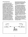
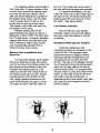
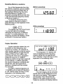
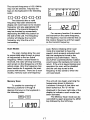
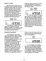
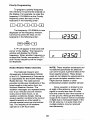
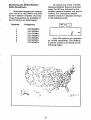
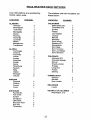
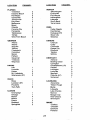
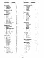
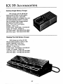
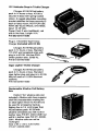
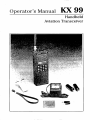
ODerator’s Manual
K x 99
Handheld
Aviation Transceiver
Table of Contents
Introduction
.........................................................................
2
General Information
Equipment Description .............................................................
License Requirements ..............................................................
Antenna Requirements .............................................................
Nickel Cadmium (NiCad) Battery Pack.....................................
Alkaline Battery Pack ................................................................
Battery Pack Installationand Removal.....................................
Low Battery Indicator ................................................................
HeadphoneIMicrophone Adapter ..............................................
3
3
4
5
5
6
6
6
KX 99 Controls
Top Controls ............................................................................ 8
Front Controls ........................................................................... 9
Side Controls .........................................................................
10
KX 99 Operation
Basic Communications Operation .........................................
VOR Navigation Modes .........................................................
Basic NAV CDI Mode ............................................................
Course Selection (Changing the OBS Setting) ......................
Centering the CDI with a TO Indication .................................
Centering the CDI with a FR (From) Indication .....................
Displaying Radial from the VOR Station ................................
Displaying Bearing to the VOR Station ..................................
Programming Memory Locations 1-9 ....................................
Recalling Memory Locations .................................................
Duplex Operation...................................................................
Scan Modes ...........................................................................
Memory Scan ........................................................................
Memory Lockout ....................................................................
Frequency Scan Mode ..........................................................
Priority Mode .........................................................................
Priority Programming .............................................................
NOAA Weather Radio Channels ...........................................
KX 99 Accessories ............................................................
In Case Service Is Required ......................
12
12
13
13
14
14
15
16
16
17
17
18
18
19
20
20
27
Inside Back Cover
Specifications .......................................................
1
11
11
Back Cover
Introduction
This manual contains information
relative to the operation and programming of the KX 99 Transceiver. It is
best to review the entire manual
before attempting use of the KX 99.
However, persons who require immediate communications capability but
do not have time to study the entire
manual can begin on page 1, Basic
Communications Operation.
Information on available accessory
items is contained in the last section
of this manual.
2
General Information
This section contains a basic
description of the KX 99 Transceiver
as well as suggestions and factors to
consider before using the KX 99.
Close adherence to these suggestions will assure a more satisfactory
performance from the equipment.
Equipment Description
License Requirements
The KX 99 is a 760 channel,
hand-held VHF aircraft communications transceiver with a 1.5 watt
transmitter output. In addition, the
KX 99 is capable of receiving 200 Nav
channels and all 7 NOAA Weather
Radio Broadcast channels. While
audio is received on all 200 Nav
channels, localizer information is not
processed on the 40 localizer
frequencies. VOR information is
processed and displayed on the liquid
crystal display (LCD) in either a radial,
bearing, or Course Deviation Indicator
(CDI) left-right informationformat. The
KX 99 contains a single receiver.
Therefore, it cannot perform the
COMM function and the NAV function
simultaneously.
The unit is powered by a selfcontained battery pack. Frequencies
and features are entered via the
keypad on the front of the unit. The
keypad and display may be illuminated for night use. Power On/Off,
volume, squelch sensitivity, keyboard
lockout, and transmitter lockout
controls are located on the top of the
unit. Jacks for headphone and
microphone are also located on the
top of the unit. The flexible antenna
may also be removed so the unit may
be used with an external antenna.
If the KX 99 Transceiver is to be
utilized in an aircraft an Aircraft Radio
Station License is required. If the
transceiver is to be used as a ground
station, then a Ground Station
Authorization is required. Included
with the KX 99 are a FCC Form 404,
Application for Aircraft Radio Station
License and a FCC Form 406,
Application for Ground Station
Authorization in the Aviation Services.
Additional copies may be obtain from
your nearest FCC Field Office.
This equipment has been
accepted by the FCC and entered on
their list of Type Accepted Equipment
as King Radio Corporation Model
KX 99, (ASY7BL KX 99).
Caution: The VHF transmitter in this
equipment is guaranteed to meet
FCC acceptance over the operating
femperature range only when a King
crystal is used in the stabilized master
oscillator. Use of other than a King
crystal is consideredan unauthorized
modification, and will void the
warranty.
3
aircraft radios and antennas so little
difficulty should be encountered when
connecting to an existing aircraft
communicationsor navigation antenna.
VOR navigation signals are
received best by a horizontal antenna
while communications signals are
received best by a vertical antenna.
This is a good point to keep in mind
when trying to receive weak signals.
When using the flexible antenna in the
cockpit or an automobile, try to place
the antenna in the center of a window
which is facing the station you are
trying to receive. Remember, if the
received station is weak and noisy,
that station is not likely to hear your
transmission. Obtain the best received
signal before attempting to call the
station.
When the KX 99 is to be used as
an emergency backup Comm or Nav
radio in an aircraft, one or two antenna
adapters (P/N 071-01443-0001) may
be installed to easily connect the
KX 99 to the existing aircraft antennas.
See diagram below.
Antenna Requirements
The flexible antenna that is
included with the KX 99 is very
convenient and may be used for both
communications and navigation
purposes. However a more efficient
antenna may be required for some
applications. For maximum utilization
of the KX 99 inside an aircraft,
automobile or other metal enclosure,
an external COMM antenna should be
used for communications and an
external NAV antenna should be used
for navigation. An external communications antenna will noticeably
improve the reception and transmission of communication radio signals;
however, it is not recommendedfor
receiving navigation signals. The use
of a horizontal type navigation
antenna will improve the reception
and the directional characteristics of
the navigation signal but it is not
recommendedfor communications
transmissions from the KX 99. The
BNC type connector, located on the
top of the unit, is standard for use on
4
Caution: To avoid possible damage
to the KX 99 make absolutely certain
that the 7 15V/230V select switch
located on the trickle charger is in the
correct position for the voltage to be
used.
Nickel Cadmium (NiCad)
Battery Pack
The standard power source
supplied with the KX 99 is a 9.6 volt,
720 mA hour, rechargeable nickelcadmium battery pack. The battery
that is shipped with the KX 99 will not
be fully charged and should be
charged prior to use.
If possible, the battery should be
fully discharged before recharging.
This will maintain the maximum useful
charge in the battery and avoid
"memory" problems associated with
this type battery. A characteristic of
NiCad batteries is that they do not
hold their charge for long periods of
time such as an alkaline battery does.
The amount of time that the
NiCad battery pack will power the
KX 99 on one charge depends on a
number of factors:
The duty cycle (amount of time the
unit is transmitting versus time
receiving a signal versus squelched
standby operation). Transmitting
discharges the battery fastest.
The volume level of the received
signal.
The temperature. A colder battery
will not last as long.
Caution:
Do not store a discharged battery
pack. Battery cell polarity may
reverse making it impossible for the
battery to fully recharge.
Do not store a battery pack where it
might be accidentally shorted. The
current capability is tremendous.
Do not crush or disassemble a
NiCad battery pack. There are toxic
chemicals inside.
Do not dispose of the battery pack
in a fire. It may explode.
Do not exceed the recommended
quick charge current. Use only the
approved chargers.
The following table shows the
approximate life of a fully charged
NiCad battery at several different duty
cycles with midlevel volume and the
battery at room temperature.
LIFE (Hrs) STBY Yo REC Yo
TX Yo
95
90
25
80
60
2
7.0
5.3
4.1
3.8
2.4
3
5
70
10
20
5
5
10
20
Alkaline Battery Pack
An optional replaceable cell
alkaline battery pack is available for
the KX 99. Alkaline batteries are used
for radios that are maintained for
emergency purposes because they
have extremely long shelf life and no
maintenance is required. ALKALINE
BATTERY PACKS ARE NOT TO BE
RECHARGED!
The KX 99 comes standard with
a trickle charger capable of operating
on either 115V or 230V. To charge
the battery; plug the charger module
into an appropriate wall outlet and
plug the other end into the connector
marked "CHRG which is located on
top of the KX 99. It takes approximately 12 hours to fully charge the
NiCad battery pack.
5
'
The alkaline battery pack holds 8
'AA" size cells. To gain access to the
8 cells, first remove the battery pack
from the KX 99 (see below). Next,
with one hand holding the outside of
the battery pack case, use the other
hand to press down firmly on the
center hub on the top of the case.
The battery cell holder will slide out
the bottom of the case.
Alkaline battery life will be
approximately the same as that of a
NiCad for a 90% STBY, 5% REC and
5% TX duty cycle. However, alkaline
batttery life will be considerably less
than a NiCad at higher duty cycles
and considerably greater than a
NiCad at lower duty cycles.
the unit. The metal tab on the side of
the unit will lock the pack into position.
To remove the battery, turn the
radio off. Press up on the metal tab on
the side of the unit while twisting the
battery pack 30"and remove it from
the radio. See figure below.
Low Battery Indicator
The KX 99 has a low battery
indicator "beep" tone that will signal
the user when the battery is almost
unusable.
HeadphonelMicrophone Adapter
External headphone and
microphonejacks are located on top
of the KX 99. The supplied headphone/microphoneadapter allows
standard aircraft headphones and
microphonesto be used with the
KX 99. The clip on the adapter should
be connected to the protruding attach
point on the right side of the unit to
provide strain relief. If a headset with
a boom mike is used, the transmit key
button on the side of the KX 99 may
be used to key the transmitter. A
separate push-to-talk switch may also
be used with the headphonelmicrophone adapter.
Battery Pack Installation and
Removal
To install the battery pack (either
NiCad or alkaline), locate the center
hub on the top of the battery pack into
the recess on the bottom of the unit.
Position the battery pack at a 30"
offset so that the two metal studs on
the battery pack go into their respective recesses on the bottom of the
unit. Apply upward pressure to the
pack while twisting the pack so that
it's sides are flush with the sides of
6
KX 99 Controls
SPEAKER
MICROPHONE
7
Top Controls
E. Headphone Jack
When a headphone is used, the
headphone connector of the
headphone/microphone adapter is
plugged into this jack. Also, an
earphone or an external speaker
having a 2.5 millimeter, 2 conductor plug may be plugged directly
into this jack. The internal speaker
is disabled when this jack is being
used.
A. OnlOffNolume Knob
Turning the knob clockwise from
the OFF position turns the unit on
and increases the speaker volume
as clockwise rotation is continued.
B. Squelch Sensitivity Adjustment
When the squelch control is turned
counterclockwise to the stop the
squelch is completely open and
receiver noise can be heard over
the speaker. Turning the squelch
control clockwise until the receiver
noise is just eliminated from the
speaker will cause only received
transmissions to be heard over the
speaker. The squelch control
must be set to tune out the
receiver noise for the scanning
function to be operational. The
squelch control should be fully
counterclockwise for WX channel
operation.
F. Microphone
When a headset having a boom
mike is used or an external
microphone is used, the microphone connector of the headphone/ microphone adaptor is
plugged into this jack. Also, an
external microphone having a 3.5
millimeter, 3 conductor plug with
the tip of the connector connected
to the mike key line and the ring
connected to the microphone
audio may be plugged directly into
this jack.
C. Antenna BNC Connector
The flexible rubber antenna or an
external antenna is connected to
this connector.
G. Transmit Lockout Button
The transmitter is disabled when
the Transmit Lockout button is
pressed in. To reenable transmitter operation, depress the
button again so it is in the "out" or
"up" position.
D. Wall Charger Input Jack
The external wall charger plugs
into this jack to recharge the
NiCad battery pack provided with
the unit. Do not attempt to use this
jack to recharge the optional
H. Keyboard Lockout Button
When the Keyboard lockout button
is in to the "in" position, no inputs
from the keyboard will be accepted. To reenable the keyboard
depress the keyboard lockout
button again so it is in the "up" or
replaceable alkaline battery pack
since damage to the unit could
occur.
8
L. WX (Weather Key)
Pressing the WX key and any of
the numeric keys 1 through 7 will
enable the unit to receive NOAA
National Weather Service Broadcasts on any of the 7 weather
channels.
Front Controls
'
j
1. Numeric Keys
The numeric keys on the keyboard
are used to enter frequencies into
the KX 99. For example, entering
the numbers 1 + 2 + 6 + 5 + 2 in
sequential order would enable the
unit to receive and transmit on
126.525MHz. Numeric buttons 3,
6 and 9 are also used in conjunction with the 2ND (2nd function)
button to control the navigation
display. Their use is explained
below.
AUTO FR (Auto From)
Pressing the 2ND key followed by
the AUTO FR key (2nd function of
the WX key) when a valid VOR
signal is being received, automatically selects the OBS setting that
centers the CDI with a FROM
indication.
J. 2ND (Second Function Key)
Depressing the Second Function
key and then any of the seven
keys on the keyboard with dual
functions will enable the second
function of the key pressed.
M. SCN (Scan Key)
Depressing the SCN key enables
the frequency scan mode.
Depressingthe key again while in
the frequency scan mode will
cause the unit to exit the scan
mode. This key is also used in
conjunction with the memory scan
mode.
K. PRI (Prlorlty Key)
Pressing the PRI key causes the
unit to monitor the Priority Frequency for any activity once every
second. Depressing the PRI key
again while in Priority mode will
cause the unit to exit Priority
mode.
LOCKOUT
Pressing the 2ND key followed by
the LOCKOUT key (2nd function of
the SCN Key) causes the displayed memory channel to be
skipped in the memory scan mode.
AUTO TO
Pressing the 2ND key followed by
the AUTO TO key (2nd function of
the PRI key) when a valid VOR
signal is being received, automatically selects the OBS setting that
centers the CDI with a TO
indicaiton.
N. CLR (Clear Key)
Depressing the CLR key clears the
display of any partial or erroneous
entries and will cause the unit to
display the last valid entry.
9
0. MEM (Memory Key)
Depressing the MEM key and then
any numeric key 0 through 9 tunes
the KX 99 to the frequency stored
in that memory location.
PRO (Program Key)
Pressing the 2ND key followed by
the PRO key (2nd function of the
MEM key) puts the KX 99 in the
program mode. The displayed
frequency is then programmed
into the desired memory channel
by pressing the appropriate
numeric key.
R. OBS (Omnibearing Selector
Key1
Pressing the 2ND key followed by
the OBS key (2nd function of the 9
key) causes the existing OBS
setting for the tuned VOR to dash.
The new OBS setting is now
selected by entering the desired
three number setting. For example, entering the numbers
0 + 2 + 5 in sequential order
would cause the 25" OBS setting
to be selected.
Side Controls
P. ERG (Bearing Key)
Pressing the 2ND key followed by
the BRG key (2nd function of 3
key) causes the bearing to the
tuned VOR to be displayed.
S. Microphone Key
(Push-to-Talk)
Enables the unit to transmit on the
selected frequency if it is a valid
communications channel.
0. RAD (Radial Key)
Pressing the 2ND key followed by
the RAD key (2nd function of the 6
key) causes the radial from the
tuned VOR to be displayed.
T. Display Lamp Switch
When the display lamp switch is
depressed the keyboard and the
display are illuminated for easy
night viewing. The lamp will
remain on as long as the switch is
depressed.
Note: The microphone is located to
transmit clarity hold mouth approxi-
the right side of the speaker (see
diagram on Page 7). For maximum
mately 1/4 inch from microphone and
speak in a normal tone of voice.
10
KX 99 Operation
Basic Communications Operation
With a charged battery pack
attached and an antenna installed on
the unit, turn the OnlOffNolume knob
to the ON position. The unit will
display the last frequency entered
when the unit was turned off. This
frequency is set at 118.00MHz at the
factory. With the squelch adjusted
completely open (counterclockwise)
adjust the volume to a comfortable
level. To eliminate the receiver noise
in the speaker adjust the squelch
control clockwise just enough until the
speaker becomes quiet. Frequencies
may now be entered via the keyboard.
NOTE: Be sure the keyboard lockout
button is in the ”up”or ‘but”position
or the unit will not accept entries from
the keyboard.
Enter a frequency by pressing
the five desired keys starting with 1 for
the1003 MHz. After the 1 has been
entered, dashes will appear for the
remaining four digits. The dashes
remain until each of the remaining
digits is entered. Each digit is checked
for validity when entered and invalid
digits will not be allowed. Pressing the
CLR key will clear any digits that have
been entered and restore the last
valid frequency that was entered.
For example, to select the
frequency 126.525MHz enter the first
five numbers of the frequency.
Depress the keys on the keyboard in
the following order:
The unit will now transmit and.
receive on 126.525MHz.
P6.W
I
NOTE: The unit will not transmit if the
transmitter lockout button is pushed
in. To transmit, the transmitter lockout
button must be in the “out”or “up”
position.
To change frequencies, simply
enter the first five numbers of the new
frequency.
7
VOR Navigation Modes
The KX 99 navigation modes are
valid onlv for VOR freauencies
between 108.00MHz and 117.95MHz.
If a localizer frequency is selected, the
letters “LOC are displayed but no
navigation information is displayed.
However, audio is still available on the
localizer frequencies.
11
Basic NAV CDI Mode
condition is indicated by the CDI bars
extending across the entire length of
the top of the display and the absence
of a TO or FR annunciation above the
selected course.
To enter a VOR frequency
(115.90MHz for example) press the
keys on the keyboard in the following
order:
I
'1'1 I I
1
I I I I I I I I I l 1 ' 1 4 I I I I I I I I I1
oesl
15.90
This display indicates that a VOR
signal is being received. The "TO-FR"
annunciator is indicating "TO", the
selected course is 85 degrees and the
CDI indicates that the course is to the
right of the aircraft three degrees. Full
scale CDI deviation is 10 degrees (10
tick marks left or right of the center).
When a VOR frequency is
selected the display shows the
frequency, the last selected course
(085) and a Course Deviation Indicator (CDI). When the selected VOR
station is not being received, a flagged
Course Selection (Changing the
OBS Setting)
To enter a course of 90" depress
the keys on the keyboard in the
following order:
Enter a valid navigation frequency
as previously described. The display
will show the frequency, the last
selected course, and the CDI.
Depress the keys in the following
order:
The OBS window will display the
selected course of 090". If a valid
navigation signal is being received the
course deviation indicator will display
deviation from the selected course of
90" and the appropriate TO or FR
(From) indication will be displayed
above the OBS window. The figure
on page 13 shows the aircraft to be
right of the 90"selected course. With
the selected course of 90°the
deviation from the selected course is
5". The 5" deviation will be indicated
by the KX 99 CDI as shown in the
display below.
1-q
I
I I I I I I I I I l+l I I I
II
IIII
I
- _ -IU8.UO
The OBS window will now display
three dashes and will accept any valid
OBS setting between 0" and 360". To
enter a valid course three digits must
be entered. For example: to enter a
course of 0", 000 would have to be
entered. To enter a course of 5",005
would have to be entered.
i90 108.00
12
For example, to center the CDI
below with a "TO" indication press the
following keys:
Centering the CDI with a TO
Indication
While a VOR signal is being
received, pressing the 2ND key
followed by the AUTO TO key will
activate the Auto Course Mode and
automatically center the CDI (Course
Deviation Indicator) with the " T O
annunciator displayed. The OBS
setting is then latched and the CDI
operates in the basic NAV CDI mode.
(Before pressing)
I
I
(After pressing)
Note: Wait approximately 10 seconds
after selecting a new NAV frequency
before using the AUTO TO feature in
order to allow the NA V filters to settle.
I
I
b
For example, to center the CDI
below with "FR" indication press the
following keys:
Centering the CDI with a FR (From)
Indication
While a VOR signal is being
received, pressing the 2ND key
followed by the AUTO FROM key will
activate the Auto Course Mode and
automatically center the CDI (Course
Deviation Indicator) with the "FR"
(From) annunciator displayed. The
OBS setting is then latched and the
CDI operates in the basic NAV CDI
mode.
(Before pressing)
I
(After pressing)
I
Note: Wait approximately 10
seconds after selecting a new NA V
frequency before using the AUTO FR
feature in order to allow the NAV
filters to settle.
13
I
For example, to enter the radial
tracking mode press the following
keys:
Displaying Radial from the VOR
Station
w+E]
RAD
The radial tracking mode is
activated by first selecting a VOR
frequency and then pressing the 2ND
key followed by the RAD key. The
CDI will no longer be displayed. A
"FR" (From) annunciation is displayed
above the OBS window. The radial
from the VOR station is displayed in
the OBS window. The radial displayed in the OBS window will
change as the aircraft changes
position with respect to the VOR
station.
(Before pressing)
(After pressing)
7
If a valid VOR signal is not being
received, a flagged condition is
indicated by dashes being displayed
in the OBS window and no "FR"
annunciation being displayed.
For example, to enter the bearing
tracking mode press the following
keys:
Displaying Bearing to the VOR
Station
The bearing tracking mode is
activated by first selecting a VOR
frequency and then pressing the 2ND
key followed by the BRG key. The
CDI will no longer be displayed. A
"TO" annunciation is displayed above
the OBS window. The bearing
displayed in the OBS window will
change as the aircraft changes
position with respect to the VOR
station.
BRG
pa+(31
(Before pressing)
(After pressing)
If a valid VOR signal is not being
received, a flagged condition is
indicated by dashes being displayed
in the OBS window and no "TO"
annunciation being displayed.
14
Programming Memory
Locations 1-9
Now that the desired frequency
has been entered, it now must be
stored in Memory Location number 1
as desired. Press the keys on the
keyboard in the following order:
Ten memory locations exist so
that frequently used frequencies can
be quickly called up and so that these
same frequencies may be scanned in
the memory scan mode.
Any frequency from 108.00 to
136.975 (135.975 on P/N 069-1026-00
version units) may be entered into any
of the ten Memory Locations, numbered 0 through 9. Memory Location 0
is reserved for duplex operation.
Duplex operation is transmitting on
one frequency and receiving on
another frequency. Ifduplex operation
is not desired, memory location 0 may
also be programmed with a single
frequency. Refer to the section
entitled Duplex Operation. To enter a
frequency into Memory Location 1
through 9 the frequency must first be
entered and then stored into the
desired Memory Location. For
example, to enter the frequency
118.90MHz into Memory Location 1:
The frequency entered will now
be displayed in the frequency window
and the Program mode will be
annunciated by "Pro" being displayed
in the OBS window. To store the
frequency 118.90MHz into any
Memory Location 1 through 9 press
the corresponding number for that
Memory Location. Example:
To store in Memory Location 1
press the 1 key on the keyboard, to
store in Memory Location 2 press the
2 key on the keyboard, and so on. In
this case press the number 1 key on
the keyboard. An M along with the
Memory Location number will be
displayed on the left side of the
display indicating the frequency
window is displaying the frequency
stored in that Memory Location. The
frequency, 118.90MHz, is now
permanently stored in Memory
Location 1 until it is reprogrammed.
First the desired frequency must
be entered. Press the keys on the
keyboard in the following order:
15
Recalling Memory Locations
Any of the frequencies from the
ten memory locations can be recalled
by simply pressing the MEM key on
the keyboard followed by the corresponding Memory Location. For
example, pressing MEM and then the
1 key will recall the frequency stored
in Memory Location 1.
To recall the frequency previously stored in Memory Location 1
press the keys on the keyboard in the
following order:
(Before pressing)
7
125.60
(After pressing)
p4+p-]
1;
The display will now show M and
1 on the left side of the display
indicating the frequency in Memory
Location 1 is being displayed. The
frequency window will display 118.90
as stored in the previous section.
I If3.90
I
Duplex Operation
Duplex operation allows the unit
to receive on one frequency and
transmit on another. An example of
when duplex operation may be used is
when transmitting to a Flight Service
Station (FSS)on 122.10MHz and
receiving the FSS over a navigation
frequency such as 111.OOMHz.
Memory Location 0 has been reserved
for this feature. In duplex operation
the receive frequency is entered and
stored first, then the transmit frequency is entered and then stored.
For example:
To enter a receive frequency of
111.OOMHz and a transmit frequency
of 122.1OMHz press the keys on the
keyboard in the following order:
The frequency 111.OOMHz will
now be displayed in the frequency
window along with the appropriate
CDI indication. Press the keys on the
keyboard in the following order:
The CDI display will be removed
and M and 0 will be displayed on the
left side to the display. The program
annunciation "Pro" will still be displayed in the 06s window and the
frequency window will display dashes.
16
The transmit frequency of 122.10MHz
may now be entered. Depress the
keys on the keyboard in the following
order:
II
I 1 I 1 1 1 I 11’1’1 I 1 I
;;
I
+
]
1
+2
F)
+
l F +l I 1
Two seconds after a valid
frequency has been entered the
display will revert back to the receive
frequency and any appropriate CDI
indication. The transmit frequency
may be checked by momentarily
depressing the Mike Key button on
the side of the unit. The frequency
window will display the transmit
frequency any time the unit is
transmitting.
0901
I II I I
11
I 1.00
For memory location 0 to receive
and transmit on the same frequency,
the frequency must be entered first as
the receive frequency and then again
as the transmit frequency.
Scan Modes
scan. Before initiating either scan
mode it is important to have the
squelch knob properly adjusted such
that the background noise in the
speaker is just eliminated. That is.
any further counterclockwise rotation
would cause the background noise to
return. If the unit is keyed during scan
operation the scan will be disabled
and the unit stay tuned to the
frequency it was tuned to when the
unit was keyed.
The scan modes allow the user
to sequentially step through a group
of frequencies to find an active
frequency. When a transmission is
received, the radio will stop scanning
and remain on that frequency until the
activity stops. After the frequency has
been inactive for 2 seconds, the scan
process will resume. There are 2 scan
modes, memory scan and frequency
The unit will now begin scanning the
frequencies stored in Memory
Locations 0 through 9 that have not
been locked out. An “S” will be
displayed in the lower right side of the
display to indicate a scan mode has
been activated.
The Memory Scan mode can be
cancelled by again pressing the MEM
key followed by the SCN key.
Memory Scan
To enable the scanning of
Memory Locations 0 through 9
depress the keys on the keyboard in
the following order:
FI+ISCNJ
17
Memory Lockout
Memory Lockout applies only to
the Memory Scan mode and not the
Frequency Scan mode. Any of the 10
Memory Locations can be omitted
from the scanning sequence. The
memory location is first displayed in
the frequency window and then
locked out. For example, to lockout
the frequency stored in Memory
Location 2 depress the keys on the
keyboard in the following order:
I
1;
1
lZ3.50
I
The frequency window will now
display the frequency stored in
Memory Location 2. An M and a 2 will
be displayed on the left hand side of
the display indicating that the
frequency stored in Memory Location
2 is being displayed. Continue to
depress the keys on the keyboard in
the following order:
An L will now appear in the lower
right corner of the display to indicate
that the frequency stored in Memory
Location 2 has been locked out of the
scan sequence. To restore a locked
out Memory Location to the Memory
Scan sequence, perform the same
sequence as above and the memory
location will be returned to the scan
sequence and the "L" will be removed
from the display.
Frequency Scan Mode
locations. After the frequencies have
been stored, depress the following
key on the keyboard:
The Frequency Scan mode
scans the frequency range in 25 KHz
steps between the frequency stored
in Memory Location 1 and the
frequency stored in Memory Location
9. Only COMM frequencies
(118.00MHz-136.975MHz) may be
scanned in the Frequency Scan
mode. For example to scan the
frequency range of 120.00 MHz to
124.50MH2, 120.00 must first be
stored in Memory Location 1 and
124.50 must be stored in Memory
Location 9. Refer to the section
entitled "Programming Memory
Locations 1 - 9 for storing 120.00 and
124.50 in the appropriate memory
120.00
An S will appear in the bottom
right corner of the display indicating
the Scan mode has been initiated.
The unit will start scanning through
the frequency range in 25KHz steps
to 124.50MHz. When the frequency
window gets to 124.50 it will reset and
start counting at 120.00 again.
18
To exit the Frequency Scan
mode at any time, simply depress the
SCN button on the keyboard again. If
the unit is keyed during scan operation the scan option will be disabled
and the unit will remain tuned to the
frequency it was tuned to when the
unit was keyed.
If either Memory Location 1 or
Memory Location 9 contains a
navigation frequency (108.00 MHz to
117.95MHz) the scan limit will be the
appropriate end of the communications band. For example, if Memory
Location 1 has a navigation frequency
stored in it the scan will begin at
118.00MHz and if Memory Location 9
has a navigation frequency stored in it
the scan will reset when it reaches
136.975MHz (135.975MHz on KPN
069-1026-00 version units).
Priority Mode
The frequency window will now
display the frequency that was selected and will display the Priority Frequency once a second. The Priority
annunciation P will also be displayed
on the left side of the display. To exit
the Priority mode at any time, simply
depress the PRI key on the keyboard
again. If there is any activity on the
Priority channel the unit will remain
tuned to the Priority frequency for two
seconds after all transmission activity
on the Priority frequency has stopped.
If the transmitter is keyed within two
seconds after receiving a transmission
on the Priority frequen-cy the unit will
remain tuned to the Priority frequency
and the Priority mode will be disabled.
It may be reenabled at any time by
depressing the PRI button again.
When the Priority mode of the
KX 99 is enabled the unit will check
the Priority frequency once a second
for any activity. If any activity is
present on the Priority frequency the
receiver will stay tuned to the Priority
frequency until there is no activity for
2 seconds. Keying the transmitter
within two seconds after the last
transmission on the Priority frequency
will disable the Priority mode. The
Priority mode cannot be enabled if a
navigation frequency is currently
displayed. (108.00MHz to
117.95MHz). A navigation frequency
cannot be programmed as the Priority
frequency.
To enable the priority mode
press the following key on the
keyboard:
P
I IB.90
I
19
Priority Programming
To program a priority frequency
into memory it must first be entered on
the display. For example, to enter the
frequency 123.50MHz as the Priority
frequency press the keys on the
keyboard in the following order:
1
7+m
+ E +m
l +pq
The frequency 123.50MHz is now
displayed on the frequency window.
Continue to press the keys on the
keyboard in the following order:
123.50
A “P“ will appear in the lower left
corner of the display. The frequency
window will display the Priority
frequency. When another frequency is
entered the Priority annunciation (“P)
and Priority frequency will no longer
be displayed.
P
123.50
NOTE: These weather broadcasts are
not tailored specifically for pilots but
can serve to give a general idea of the
local weather picture. These broadcasts do not delete the requirement to
get current aviation weather from a
Flight Service Station or other
professional aviation weather service.
NOAA Weather Radio Channels
The National Oceanic and
Atmospheric Administration (NOAA)
of the U.S. Department of Commerce
is responsible for the NOAA Weather
Radio Service. The radio service
provides continuous broadcasts of the
latest weather information from the
National Weather Service. The
weather messages are repeated every
four to six minutes and are revised
every one to three hours, or as
weather conditions dictate. During
severe weather conditions the normal
taped forecasts are interrupted to
provide special warnings and advisories. The majority of the stations
operate on a 24 hour basis.
Since reception is limited to line
of sight of the antenna, range of the
signal is usually less than 40 miles
from the antenna site if the receiver is
on the ground. Although the effective
range of the receiver will be increased
in flight due to increased height of the
KX 99 antenna, it is quite likely that
multiple stations may be received
simultaneously.
20
To receive any of the 7 NOAA
National Weather Service channels
press the WX key followed by the
weather channel number you wish to
receive. For example to receive
weather channel 1 depress the keys
in the following order:
Radio Broadcasts
Broadcast frequencies ranging
from 162.40 to 162.55MHz are used
for the 7 different weather channels.
These frequencies are available on
the KX 99 and are listed below:
Channel
1
2
3
4
5
6
7
Frequency
162.550MHZ
162.400MHz
162.475MHz
162.425MHz
162.450MHz
162.500MHz
162.525MHz
Over 350 stations are operated
by NOAA nationwide. The stations
and their locations are listed on the
following pages.
21
NOAA WEATHER RADIO NETWORK
Over 350 stations are operated by
NOAA nation wide.
The stations and their locations are
listed below:
LOCATION
IS)CATION
CHANNEL
CALIFORNIA
ALABAMA
4
Bakersfield (DT)
Coachella (DT)
Eureka
2
2
3
Fresno
2
Los Angeles
Lindsay
Merced
Monterey
Point Arena
Redding (DT)
Sacramento
San Diego
San Francisco
San Luis Obispo
Santa Barbara
1
6
1
2
2
Anniston
Birmingham
*Columbia
Demopolis
Dozier
Florence
Huntsville
Louisville
Mobile
Montgomery
Tuscaloosa
1
3
2
3
1
3
1
2
2
ALASKA
Anchorage
Cordova
Fairbanks
Homer
Juneau
Ketchikan
Kodiak
Nome
Petersburg
Seward
Sitka
Valdez
Wrangell
Yakutat
1
1
1
Alamosa (DT)
Colorado Springs
Denver
Grand Junction
Greeley
Longmont
Pueblo
Sterling
1
2
2
1
1
2
3
3
1
1
2
1
2
2
CONNECTICUT
Hartford
Meriden
New London
2
1
3
2
1
DELAWARE
2
1
Lewes
1
DISTRICT OF COLUMBIA
ARKANSAS
Fayetteville
Fort Smith
Gurdon
Jonesboro
Little Rock
Mountain View
Star-City
Texarkana
1
COLORADO
2
1
1
1
1
1
1
1
1
2
2
ARIZONA
Flagstafl
Phoenix
Tucson
Yuma
CHANNEL
Washington, D.C.
3
2
3
1
1
2
2
1
22
1
LOCATlON
CHANNEL
LOCATION
INDIANA
FLORIDA
'Clewiston
Daytona Beach
Fort Myers
Gainesville
Jacksonville
Key West
Melbourne
Miami
Orlando
Panama City
Pensacola
Tallahassee
Tampa
West Palm Beach
'Bloomington
Evansville
Fort Wayne
Indianapolis
Lafayette
South Bend
Terre Haute
2
2
3
3
1
2
1
1
1
2
2
1
Cedar Rapids
Des Moines
Dubuque (DT)
Sioux City
Waterloo
3
1
1
1
3
2
2
3
1
2
3
1
KANSAS
Chanute
Colby
Concordia
Dodge City
Ellsworth
Topeka
Wichita
2
1
1
7
2
2
3
1
2
6
3
2
3
1
3
2
3
1
KENTUCKY
Ashland
Bowling Green
Covington
Elizabethtown (LP)
Hazard
Lexington
Louisville
Mayfield
Pikeville (LP)
Somerset
HAWAII
Hilo
Honolulu
Kokee
Mt. Haleakala
Waimanato (DT)
5
IOWA
3
GEORGIA
Athens
Atlanta
Augusta
'Baxle y
Chatsworth
Columbus
Macon
Pelham
Savannah
'Valdosta
Waycross
CHANNEL
1
1
2
2
2
1
2
1
2
3
2
3
3
2
1
IDAHO
Boise
Lewiston (DT)
Pocatello
Twin Falls
LOUISIANA
1
1
1
2
ILLINOIS
Champaign
Chicago
Marlon
Moline
Peoria
Rockford
Springfield
1
1
4
1
3
3
Alexandria
'Baton Rouge
3
Buras
3
Lafayette
Lake Charles
Monroe
Morgan City
New Orleans
Shreveport
1
2
1
3
2
1
2
MAINE
2
'Caribou
'Dresden
Ellsworth
Portland
23
7
3
2
1
LOCATION
CHANNEL
LOCATION
MARYLAND
Baltimore
Hagerstown
Salisbuty
MISSOURI (CONT'D)
2
Kansas City
St. Joseph
St. Louis
Sikeston
Springfield
3
3
MASSACHUElTS
Boston
Hyannis
Worcester
1
1
2
1
2
1
2
1
2
1
Glasgow
1
Great Falls
Havre (DT)
Helena
Kalispell
Miles City
Missoula
1
2
2
1
2
2
Bassett
Grand Island
Holdrege
Lincoln
Merriman
,Norfolk
North Platte
Omaha
Scottsbluff
3
1
1
2
1
3
3
1
3
2
3
3
2
1
1
2
1
NEVADA
1
2
Elko
ElY
Las Vegas
Reno
Winnemucca
3
1
1
1
2
1
1
2
NEW HAMPSHIRE
2
2
3
1
2
1
2
Concord
2
NEW JERSEY
Atlantic City
2
NEW MEXICO
Albuquerque
Clovis
Des Moines
Farmington
Hobbs
Las Cruces
Ruidoso
Santa Fe
MISSOURI
Columbia
Camdenton
Hannibal
Hermitage
JoplinCarthage
Billings
Butte
NEBRASKA
MISSISSIPPI
Ackerman
Booneville
Bude
'Columbia
Gulfport
Hattiesburg
lnverness
Jackson
Meridian
Oxford
1
2
2
MONTANA
1
1
MINNESOTA
Detroit Lakes
Duluth
International Falls
Mankato
Minneapolis
Rochester
Saint Cloud (DT)
Thief River Falls
Willmar (DT)
1
2
3
MICHIGAN
Alpena
Detroit
Flint
Grand Rapids
Houghton
Marquette
'Onondaga
Sault Sainte Marie
Traverse City
CHANNEL
2
1
3
5
1
24
2
3
1
3
2
2
1
1
LOCATION
LOCATION
CHANNEL
OREGON
NEW YORK
Albany
Binghamton
Buffalo
Elmira
Kingston
New York City
'Riverhead
Rochester
Syracuse
Astoria
Brookings
Coos Bay
Eugene
Klamath Falls
Medford
Newport
Pendleton
Portland
Roseburg
Salem
1
3
1
1
3
1
3
2
1
NORTH CAROLINA
Asheville
Cape Hatteras
Charlotte
Fayetteville
New Bern
Raleigh/Durham
Rocky Mount
Wilmington
Winston-Salem
2
3
Allentown
Clearfield
Erie
Harrisburg
Johnstown
Philadelphia
Pittsburgh
State College
Wilkes-Barre
Williamsport
2
1
3
4
2
2
1
2
1
3
3
2
1
2
1
2
3
1
3
1
2
PUERTO RlCO
2
Maricao
San Juan
2
2
2
2
1
2
RHODE ISLAND
Providence
SOUTH CAROLINA
2
3
Beaufort
Charleston
Columbia
Florence
Greenville
Myrtle Beach
Sumter (LP)
1
1
3
2
2
1
OKLAHOMA
Clinton
Enid
Lawton
McAlester
Oklahoma City
Tulsa
1
2
2
2
2
2
OHIO
Akron
Cambridge
Cleveland
Columbus
Dayton
Lima
Sandusky
Toledo
2
PENNSYLVANlA
3
3
NORTH DAKOTA
Bismarck
Dickinson
Fargo
Jamestown
Minot
Petersburg
Williston
CHANNEL
SOUTH DAKOTA
3
3
1
3
2
1
Aberdeen
Huron
Pierre
Rapid City
Sioux City
25
2
LOCATION
CHANNEL
LOCATION
TENNESSEE
Bristol
Chattanooga
Cookeville
Jackson
Knoxville
Memphis
Nashville
Shelbyville
Waverly
VERMONT
1
1
Burlington
'Marlboro
Windsor
2
4
3
VIRGINIA
Heathsville
'Lynchburg
Norfolk
Richmond
Roanoke
1
3
2
2
1
1
3
3
WASHINGTON
2
1
2
Neah Bay
Olympia
Seattle
Spokane
Wenatchee
Yakima
3
3
1
1
1
2
1
3
1
2
3
1
WEST VIRGINIA
Beckley
Charleston
Clarksburg
Gilbert
Hinton
Romney
Spencer
Sutton
2
3
1
1
2
3
2
1
6
2
1
7
4
7
6
5
2
WISCONSIN
1
La Crosse (DT)
Green Bay
Madison
Menomonie
Milwaukee
Wausau
2
1
1
3
3
2
3
3
1
1
1
2
2
3
WYOMING
Casper
Cheyenne
Lander
Sheridan (DT)
.UTAH
Logan
Cedar City
Vernal
Salt Lake City
3
1
3
3
TEXAS
Abilene
Amarillo
Austin
Beaumont
Big Spring
Brownsville
Bryan
Corpus Christi
Dallas
Del Rio (DT)
El Paso
Fort Worth
Galveston
Houston
Laredo
Lubbock
Lufkin
Midland
Paris
Pharr
San Angelo
San Antonio
Sherman
Tyler
'Victoria
Wac0
Wichita Falls
CHANNEL
2
2
2
1
1
3
3
3
NOTES:
3. Stations marked (DT) operate less
than 24 hourslday; however, hours
1. Stations marked with an asterisk
(*) are funded by private interest
are extended when possible during
severe weather.
groups.
2. Stations marked (LP) are low
powered experimental repeater
stations serving a very limited local
area.
26
KX 99 Accessories
Desktop Single Battery Charger
Will charge one KX 99 NiCad
battery pack to 90% of the battery
capacity in one hour. Once the
charging function is complete, the unit
will automatically switch to a trickle
rate to maintain the charge without
damaging the battery pack.
Size: 7.0 x 3.75 x 3.5 inches.
Weight: 3 Ibs. 2 02.
Power Cord: Grounded, 3 Conductor
Cable, 78" length. 50/60 Hz.
120 VAC input - PIN 062-00103-0080
240 VAC input - PIN 062-00103-0081
Desktop Five Unit Battery Charger
Will charge up to five KX 99
NiCad battery packs to 90% of the
battery capacity in one hour.
Size: 18.5 x 7.25 x 5.5inches.
Weight: 15 Ibs. 8 02.
Power Cord: Grounded, 3 Conductor
Cable, 78" length. 50/60 Hz.
120 VAC input - P/N 062-00108-0080
240 VAC input - P/N 062-00108-0081
12V Vehicular Dropln Trickle Charger
Charges KX 99 NiCad battery
pack in 14 hours or less. KX 99 is
secured in base with spring loaded
rollers. A rugged adjustable mounting
bracket attaches the base securely to
dash or lamp mount. NOT FOR USE
WITH 28V ELECTRICAL SYSTEMS.
Input: 12-18 VDC.
Power Cord: 2 wire (redhlack), red
with in-line fuse, Length 10 ft.
P/N 062-00107-0080
Plug in 115V/230V Wall Trickle
Charger (Included with KX 99)
Charges KX 99 NiCad battery
pack in 14 hours or less. Standard
115 VAC wall receptacle style with
plug-in to KX 99. Unit has 230V
switch position also. 50/60 Hz.
P/N 015-00190-0000
Cigar Lighter Trickle Charger
Charges KX 99 NiCad battery
pack in 14 hours or less. Standard
cigar lighter plug and plug-in to KX 99.
May be used on 12-28V electrical
systems.
P/N 155-02481-0000
Replaceable Alkaline Cell Battery
Box
Holds 8 "AA" alkaline cells (not
included). Alkaline cells have superior
shelf-life characteristics making this
an ideal option when the KX 99 is to
be used for emergency backup.
Battery box is 1/4 inch longer than
NiCad battery pack. KX 99 with
alkaline cell battery box will not fit in
leather case P/N 071-00041-0081 but
will fit in leather case PIN 071-000380081. Alkaline cells can not be
recharged.
Size: 2.55 x 1.50 x 3.20 inches
P/N 071-00056-0000
28
Nicad Battery Pack
(Included with KX 99)
t
May be recharged with any of
the battery chargers previously
described. 720mAH.
Size: 2.55 x 1.50 x 2.95 inches.
PIN 200-03224-0081
HeadphonelMicrophoneAdapter
(Included with KX 99)
Allows standard size headphone
and microphone plugs to work with
KX 99. PIN 071-00049-0000
Antenna Adapter with Cable
Allows KX 99 to use existing
external aircraft COMM or NAV
antennas. One adapter required for
COMM antenna and one for NAV
antenna. See page 4 of manual for
additional information.
PIN 071-01443-0001
Earphone
Includes ear loop. 2 conductor,
60 inch cable. 2.5 mm connector.
Impedance: 2000 Ohms.
PIN 071-00039-0080
29
Flexible Antenna
(Included with KX 99)
BNC connector.
P/N 071-01441 -0000
Leather Case with Cutouts, Cover
and Belt Loop
Deluxe leather case. Has cutouts
to allow viewing display and oeration of
KX 99 when unit is in case. Unique
holster clip traps the battery pack in the
bottom of the case yielding maximum
access to the radio top controls.
Includes leather top cover and detachable swivel belt loop. The belt loop will
accept up to 2 314 inch wide belts.
Note: KX 99 with optional alkaline cell
battery box will not fit in this leather
case. Order system number
KX 0099-51.
Leather Case with Cutouts
(Less cover and belt loop)
Has cutouts to allow viewing
display and operation of KX 99 when
unit is in case. Note: KX 99 with
optional alkaline cell battery box will
not fit in this leather case.
P/N 071-00041-0081
30
Leather Cover Only for Leather Case
Fits both leather cases
(071-00041-0081 8.071-00038-0081)
PIN 071-00034-0080
Belt Loop Only for Leather Case
Fits both leather cases
(071-00041-0081 8. 071-00038-0081)
!I
PIN 071-00037-0080
Leather Case with Cover
and Belt Loop
Deluxe leather case. Unique
holster clip traps the battery pack in
the bottom of the case yielding
maximum access to the radio top
controls. Includes leather top cover
and detachable swivel belt loop. The
belt loop will accept up to 2 314 inch
wide belts.
Order system number KX 0099-50.
31
Leather Shoulder Strap for
Case
PIN 071-00036-0080
Cloth Carrying Case
Protective padded case for
transportinglstoring KX 99. Separate
pouch on side for antenna storage.
KX 99 controls not accessible when in
carrying case.
PIN 071-06118-0000
Belt Clip
(Included with KX 99)
PIN 047-07525-0001
Belt Clip Screws (Not Shown)
(Included with KX 99)
2 Required.
PIN 089-06617-0004
KX 99 Operators Manual (Not
shown)
(Included with KX 99)
PIN 006-08428-0000
Operating Guide Decal (Not 'shown)
(2 included with KX 99)
PIN 057-03435-0000
32
In Case Service is Required
In case you have difficulties with
the operation of the KX 99, first check
these items:
Make sure the battery is
charged.
Check that the squelch knob is
properly adjusted.
Verify that you have followed
the correct operating procedures
described in this manual.
If repairs are required, the unit
may be taken to your nearest authorized BendidKing Service facility or it
may be sent directly to the factory
service department.
BEIYDIXIKIG
Customer Service Department
400 N. Rogers Road
Olathe, KS 66062
When shipping the unit to the
factory service department make sure
everything is securely packaged
(ideally in the original shipping
carton). Whenever sending any
KX 99 back to the factory service
department, fill out the foldout card
attached to this page (KX 99 Repair
Request) and return this card with the
unit. If the card is not available
please include the following information with the KX 99 or accessory:
w
k
n
Name, address, daytime phone
number, KX 99 Serial Number, billing
requested (Master Card, VISA, or
COD), Card No., Expiration date,
Warranty Certificate Number (if unit to
be repaired under warranty). Also
give a specific description of the
problem.
Z
0
k
rr
a
3
x d
y m
X
W
Specifications
~
KX 99 Technical Characteristics
Compliance
Physical Characteristics
Frequency Stability
Operating Temperature Range
Power Requirements
Receive: Squelched
Receive: Full volume
Transmit:
Receiver
Frequency Range
~~
FCC: Part 87
8.O"H x 2.6W x 1.6"D, Weight: 1.75 Ibs.
.002%
-20 to +55 Degrees C.
9.6 VDC
70 mA.
200 mA.
1200 mA.
108 to 136.975 MHz (PIN 069-1026-01)
161.50 to 163.275 MHz Weather
- 6 d B a t r 5KHz
AM 6 dB
at 1 pV soft
'A
Selectivity
Sensitivity
N
Wx 12 dB SlNAD at 1 pV.soft
Adjacent Channel Rejection
-40 dB Comm and -60 dB Nav
Channel Spacing
25 KHz Comm and 50 KHz Nav
Audio Output Power and Distortion 500 mW into 8 Ohms, 15%
Transmitter
Transmitter Power
Duty Cycle
Microphone
1.5 Watts Minimum
No damage continuously keyed
Internal Electret or External
BENDIXIKING
General Aviation Avionics Division
400 North Rogers Road
Olathe. Kansas 66062-1212
Telex 669916 KINGRAD Fax 913-791-1302
Outside USA 8 Canada (913) 782-0700
USA 8 Canada (913) 7820100
VI
1992 Allied-Signal Inc.
10/92 006-08428M)o 3K
Printed in Singapore
BendixMingB is a registeredtrdemark of Allied-Signal Inc.