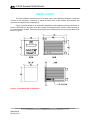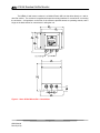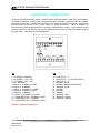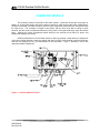
1
Model A15/66 Residual Sulfite Monitor Home Office Analytical Technology, Inc. 6 Iron Bridge Drive Collegeville, PA 19426 Ph: (800) 959-0299 (610) 917-0991 Fax: (610) 917-0992 Email: [email protected] European Office ATI (UK) Limited Unit 1 & 2 Gatehead Business Park Delph New Road, Delph Saddleworth OL3 5DE Ph: 0800-018-4020 + 44 (0) 1457-873-318 Fax: + 44 (0) 1457-874-468 Email: [email protected] PRODUCT WARRANTY Analytical Technology, Inc. (Manufacturer) warrants to the Customer that if any part(s) of the Manufacturer's products proves to be defective in materials or workmanship within the earlier of 18 months of the date of shipment or 12 months of the date of start-up, such defective parts will be repaired or replaced free of charge. Inspection and repairs to products thought to be defective within the warranty period will be completed at the Manufacturer's facilities in Collegeville, PA. Products on which warranty repairs are required shall be shipped freight prepaid to the Manufacturer. The product(s) will be returned freight prepaid and allowed if it is determined by the manufacturer that the part(s) failed due to defective materials or workmanship. This warranty does not cover consumable items, batteries, or wear items subject to periodic replacement including lamps and fuses. Gas sensors, except oxygen sensors, are covered by this warranty, but are subject to inspection for evidence of extended exposure to excessive gas concentrations. Should inspection indicate that sensors have been expended rather than failed prematurely, the warranty shall not apply. The Manufacturer assumes no liability for consequential damages of any kind, and the buyer by acceptance of this equipment will assume all liability for the consequences of its use or misuse by the Customer, his employees, or others. A defect within the meaning of this warranty is any part of any piece of a Manufacturer's product which shall, when such part is capable of being renewed, repaired, or replaced, operate to condemn such piece of equipment. This warranty is in lieu of all other warranties (including without limiting the generality of the foregoing warranties of merchantability and fitness for a particular purpose), guarantees, obligations or liabilities expressed or implied by the Manufacturer or its representatives and by statute or rule of law. This warranty is void if the Manufacturer's product(s) has been subject to misuse or abuse, or has not been operated or stored in accordance with instructions or if the serial number has been removed. Analytical Technology, Inc. makes no other warranty expressed or implied except as stated above. TABLE OF CONTENTS UNPACKING .............................................................................................................................................................. 2 INTRODUCTION ....................................................................................................................................................... 3 SPECIFICATIONS ..................................................................................................................................................... 5 ELECTRONICS UNIT .............................................................................................................................................. 5 CHEMISTRY MODULE .......................................................................................................................................... 5 SAMPLE OVERFLOW CHAMBER ........................................................................................................................ 5 INSTALLATION......................................................................................................................................................... 6 ELECTRICAL CONNECTIONS .............................................................................................................................. 9 CHEMISTRY MODULE.......................................................................................................................................... 11 CHEMISTRY MODULE REAGENTS ................................................................................................................... 13 PURCHASING REAGENT SUPPLIES.................................................................................................................. 14 ACID PICKUP TUBING CONNECTION .............................................................................................................. 15 SAMPLE INLET OVERFLOW............................................................................................................................... 16 START-UP ................................................................................................................................................................. 17 OPERATING MODE .............................................................................................................................................. 18 FRONT PANEL LOCK ........................................................................................................................................... 18 CHEMISTRY MODULE STARTUP ...................................................................................................................... 19 CONFIGURATION .................................................................................................................................................. 20 OPERATION ............................................................................................................................................................. 23 ZEROING THE SYSTEM....................................................................................................................................... 23 CALIBRATION ...................................................................................................................................................... 24 IMMEDIATE CALIBRATION .............................................................................................................................. 24 POST CALIBRATION ........................................................................................................................................... 25 MIXING A SULFITE STANDARD ....................................................................................................................... 25 CONTROL & ALARM OUTPUTS ......................................................................................................................... 26 CONTROL RELAYS .............................................................................................................................................. 26 PULSE FREQUENCY MODULATION (PFM) CONTROL .................................................................................. 27 PULSE WIDTH MODULATION (PWM) CONTROL ........................................................................................... 28 ANALOG OUTPUT ............................................................................................................................................... 29 SIMULATE MODE OF OPERATION ................................................................................................................... 29 TEMPERATURE MEASUREMENT .................................................................................................................... 29 SAMPLE SYSTEM CLEANING ............................................................................................................................. 30 CLEANING SYSTEM OPERATION ..................................................................................................................... 30 MAINTENANCE....................................................................................................................................................... 32 SENSOR SERVICE ................................................................................................................................................ 32 REACTOR MAINTENANCE................................................................................................................................. 32 PUMP TUBING REPLACEMENT ......................................................................................................................... 33 AIR FILTER REPLACEMENT .............................................................................................................................. 34 TROUBLESHOOTING ............................................................................................................................................ 35 MONITOR RESET.................................................................................................................................................. 36 SPARE PARTS LIST - MODEL A15/66................................................................................................................. 37 TABLE OF FIGURES Figure 1 - Typical Res. SO2 Monitoring System ........................................................................... 4 Figure 2 - Panel Mount Dim. & Installation ................................................................................... 6 Figure 3 - Nexa 4X Wall Mount Dim. & Installation ....................................................................... 7 Figure 4 - Chemistry Module Dimensions ..................................................................................... 8 Figure 5 - Electrical Connections .................................................................................................. 9 Figure 6 - Chemsitry Module Connections .................................................................................. 10 Figure 7 - Chemistry Module Layout ........................................................................................... 11 Figure 8 - Reagent Bottle Mounting Bracket ............................................................................... 14 Figure 9 - Solution Feed Assembly ............................................................................................. 15 Figure 10 - Sample Inlet Overflow Arrangement ......................................................................... 16 Figure 11 - Pump Head Assembly Exploded View ..................................................................... 34 ATI A15/66 Residual Sulfite Monitor UNPACKING When you receive your A15/66 Residual Sulfite Monitor, open the shipping packages and inspect the contents to be sure that all items have been received. The following items should be included: Quantity 1 - Model A15/66 Sulfite Monitor Electronics (panel mount or NEMA 4X) Quantity 1 - Sulfite Monitor Chemistry Module Quantity 1 - 20 ft. sensor interconnect cable Quantity 2 - Gas Phase Sulfite Sensor (sensor keeper plugged into back of one sensor) Quantity 1 - Spare Parts Kit Quantity 1 - Reagent Bottle Wall Bracket (unless 00-1261 SS plate is ordered) Quantity 1 - Square 1-Gallon Reagent Bottle In addition to the standard items listed above, any additional spare parts, cable, or spare sensors that were ordered separately will be included. Compare the contents of the shipping container with the packing list. The items listed above are the standard components that are included with every standard A15/66 sulfite monitor. Any other items will be listed separately on the packing list. Check the contents of the shipping container carefully to insure that nothing is overlooked. Should you find anything missing from the shipment, immediately contact the ATI sales department by phone, fax., or email using the information shown on the first page of this manual. 2 O&M Manual Rev-W (8/10) ATI A15/66 Residual Sulfite Monitor INTRODUCTION The Model A15/66 is an on-line monitoring system designed for the continuous measurement of sulfite ion (SO3-) in solution. The full scale operating range of the system may be selected by the user for 0-2.000 PPM or 0-20.00 PPM, and the sensing system will operate on water streams with temperatures from 0 to 50C. The Monitor is designed for dechlorination applications where sulfur dioxide gas or sodium sulfite or bisulfite are used to remove chlorine from water streams. Sulfite ion measurement is made in the A15/66 system by pumping a small amount of sample out of the inlet overflow assembly, mixing the sample with acid to convert the sulfite ion to sulfur dioxide gas, and then air stripping the SO2 for measurement in the gas phase. A sulfur dioxide gas sensor located in the flow block next to the air stripping chamber measures the concentration of SO2 in the gas stream, and is connected to an electronic module with converts sensor signals to a direct concentration display. The measured sulfite concentration is displayed on a backlit liquid crystal display on the front of the instrument. Depending on the full scale operating range selected, the unit will display sulfite with a resolution of either 0.01 PPM (10 PPB) or 0.001 (1 PPB). A 4-20 mA output is provided for recording or data logging. The output can be programmed for a variety of ranges as is described later in this manual, with a minimum range of 0-0.1 PPM and a maximum range of 0-20 PPM. Alarm contacts are also standard in the electronic package and may be used either for simple control schemes or for signaling operators of abnormal operating conditions. The standard model A15/66 system includes three main components, a wall mounted NEMA 4X electronics unit, a chemistry module housed in a wall-mount enclosure, and a sample inlet overflow chamber with standoff bracket. The electronics is also available in a panel mount version if preferred for a particular application. For connection of the chemistry module to the electronics, a 20' sensor cable is supplied, and the cable length can be increased to 100' maximum. Figure 1 on the following page shows a typical installation of this monitoring system. For convenience in installation, a special stainless steel mounting panel is available. This panel provides mounting locations for the monitor, chemistry module, and overflow chamber. In addition, it contains a shelf at the bottom for locating the reagent containers used in normal operation. The drawing in figure 1 provides mounting hole dimensions for the optional stainless steel mounting panel. While the monitor is suitable for outdoor mounting, the chemistry module should have additional protection mounted outdoors. It is best to mount the chemistry module and reagents inside a generalpurpose enclosure to keep wind driven rain off of the pumps located on the bottom of the chemistry module. Do not put the chemistry module in a sealed enclosure. Sample leakage from the overflow chamber must have a place to drain in case of an overflow or sample line break. 3 O&M Manual Rev-W (8/10) ATI A15/66 Residual Sulfite Monitor Figure 1 - Typical Res. SO2 Monitoring System 4 O&M Manual Rev-W (8/10) ATI A15/66 Residual Sulfite Monitor SPECIFICATIONS ELECTRONICS UNIT Range: Repeatability: Linearity: Response Time: Display: Temperature: Control Relays: Control Mode: Alarm Relay: Analog Output: Operating Conditions: Power: Enclosure: 0-2.000 or 0-20.00 PPM ± 0.01 PPM 0.1% of F.S. 90% in 5 Minutes 16 character alphanumeric backlit LCD 0-50°C with 100 ohm Pt. RTD Two SPDT relays, 5A @ 220 VAC resistive. Programmable deadband and time delay. On/Off, pulse width modulation, pulse frequency modulation Independent SPDT relay, 5A @ 220 VAC resistive. Programmable for actuation on high/low values or system failure. Isolated 4-20 mA, 600 ohm maximum load. Programmable output span. Output may be inverted. 0-50° C., 0-95% R.H. non-condensing. 110/220 VAC ±10%, 50/60 Hz. Panel mount standard, NEMA 4X wall mount optional. CHEMISTRY MODULE Sensor: Sensor Cable: Sample Pump: Reagent Pump: Air Supply: Air Stripping Chamber: Temperature Limits: Power: Enclosure: Membraned SO2 Gas Sensor 20 feet standard, 100 feet maximum Internal Tubing Pump, 5 cc./min. Internal Tubing Pump, 0.06 cc/min. (uses 2 tubes) Diaphragm air pump with rotameter flow control Cast Acrylic 0-40° C. 120 VAC, 60 Hz., 220 VAC, 50 Hz. Optional NEMA 1 SAMPLE OVERFLOW CHAMBER Material: Recommended Sample Rate: Sample Inlet: Sample Drain: Mounting Bracket: Clear Acrylic 7-30 GPH (0.45 – 1.9 LPM) ¼” I.D. Hose Barb (1/8” FNPT) ½” I.D. Hose Barb (3/8” FNPT) Aluminum 5 O&M Manual Rev-W (8/10) ATI A15/66 Residual Sulfite Monitor INSTALLATION The main installation requirements of ATI's sulfite monitor are mechanical installation, connection of power to the electronics, connection of sample and drain lines to the constant head flowcell, and connection of reagents to the reagent pump. Figure 2 provides details on the mechanical installation of the standard panel mounted electronic monitor. Dimensions on the panel cutout are included, and the panel cutout must be made accurately as the cutout tolerance is small. Panel mounting brackets are included with the monitor and are attached as shown in Figure 2. Figure 2 - Panel Mount Dim. & Installation 6 O&M Manual Rev-W (8/10) ATI A15/66 Residual Sulfite Monitor The NEMA 4X wall mount enclosure is a Molded Plastic ABS unit that bolts directly to a wall or other flat surface. The enclosure is supplied with special mounting brackets for convenience in mounting the enclosure. A hinged door on the front of the enclosure provides access to operating controls, and a hinge on the back section for convenience in wiring the unit. Figure 3 - Nexa 4X Wall Mount Dim. & Installation 7 O&M Manual Rev-W (8/10) ATI A15/66 Residual Sulfite Monitor The chemistry module consists of an ABS enclosure housing sample and reagent pumps plus the air supply and reactor system used to measure sulfite concentration. The chemistry module is designed for wall mounting in a protected location. Although the enclosure is suitable for outdoor use, it is best to provide an additional enclosure around this module if mounted outdoors. Dimensions of this unit are shown in Figure 4. Figure 4 - Chemistry Module Dimensions CAUTION: Chemistry modules should be installed in a protected environment. Indoor installation is preferable. If outdoor installation is required, protection against freezing is required. Never install outdoors in an environment where ambient temperatures will exceed 40 C. 8 O&M Manual Rev-W (8/10) ATI A15/66 Residual Sulfite Monitor ELECTRICAL CONNECTIONS AC power must be connected to both the monitor and the chemistry module. Refer to Figure 5 below for the proper connections. A power cord is supplied with each unit for AC connection and a 6- conductor interconnect cable (20 ft.) is supplied for connection of the chemistry module to the monitor. Note that the terminal blocks at the rear of the monitor unplug for wiring convenience. Figure 6 provides the interconnection wiring diagram between the chemistry module and the monitor. The chemistry module can be located up to 100 feet from the monitor provided that connection is made with a single length of #31-0037 cable. Cable must be ordered separately. TB1 TB2 1 - AC POWER - NEUTRAL 2 - AC POWER - 110V - HOT 3 - AC POWER - 220V - HOT 4 - AC - GROUND 5 - RELAY A - NORMALLY OPEN 6 - RELAY A - COMMON 7 - RELAY A - NORMALLY CLOSED 8 - RELAY B - NORMALLY OPEN 9 - RELAY B - COMMON 10 - RELAY B - NORMALLY CLOSED 11 - ALARM RELAY C/D - NORMALLY OPEN 12 - ALARM RELAY C/D - COMMON 13 - ALARM RELAY C/D - NORMALLY OPEN 14 - MA OUTPUT - (+) 15 - MA OUTPUT - (+) (OPTIONAL DUAL) 16 - MA OUTPUT - (-) 17 - SENSOR - WHITE 18 - SENSOR - BROWN OR ORANGE 19 – SENSOR - BLUE 20 - UNUSED 21 - UNUSED 22 - UNUSED 23 – SENSOR – RED 24 – SENSOR – BLACK 25 – SENSOR – GREEN Figure 5 - Electrical Connections 9 O&M Manual Rev-W (8/10) ATI A15/66 Residual Sulfite Monitor To wire the chemistry module, you need to open the center compartment of the assembly. On the left side of the enclosure is a slot for releasing the latch. Slide a small screwdriver into the slot and push the screwdriver handle toward the side of the enclosure. The latch will snap open and you can release the catch, allowing the front part of the chemistry module to swing open on the right hand hinge. If you wish, you can completely remove the front section by unplugging the pump terminal block, the upper terminal block marked “to sensor”, and disconnecting the air line from the pump. With these disconnected, you can open the right hand latch and remove the entire front section. Figure 6 - Chemsitry Module Connections 10 O&M Manual Rev-W (8/10) ATI A15/66 Residual Sulfite Monitor CHEMISTRY MODULE The chemistry module is the heart of the sulfite monitor. Inside this module are the pumps, air supply, air control instruments, and sensor element required to make an accurate sulfite measurement. All items are housed in an ABS enclosure, with the main components mounted on the front panel inside the clear cover. The enclosure is hinged in two places, with the front cover able to swing in either direction, and the center compartment allowed to swing open on the right hand hinge (open left release latch). Opening the center compartment allows access to the terminal circuit board, air pump, and sample and reagent pump wiring. Sulfite measurement in the chemistry module is done by pumping a small amount of sample out of the inlet overflow chamber, mixing the sample with sulfuric acid to convert sulfite to sulfur dioxide gas, and then air stripping the SO2 for measurement in the gas phase. Figure 7 provides a view of the chemistry module components. Figure 7 - Chemistry Module Layout 11 O&M Manual Rev-W (8/10) ATI A15/66 Residual Sulfite Monitor In operation, sample flows to the inlet chamber of the overflow assembly. Most of the sample overflows to waste. A small amount of sample (5 cc/min.) is pumped out of the inlet chamber. Sulfuric acid solution is supplied by the second pump and mixed with the sample in the mixing “T”, converting the sulfite ion to molecular sulfur dioxide gas as follows. SO3= + 2 H+ SO2 + H2O The reacted sample then moves to the air stripping chamber. In the stripping chamber, air is injected into the incoming sample at a controlled rate. Sulfur dioxide gas is stripped from the sample into this air stream and carried out of the reactor through a passage in the reactor cap. A special gas sensor located in the flow block to the right of the stripping chamber measures the SO2 concentration, providing a signal to the A15/66 electronics module. Air for the stripping process is provided by an air pump located on the circuit board in the rear compartment of the chemistry module. Air from this pump is first filtered and then pumped through a rotameter with flow indicator. The rotameter is used to adjust the flow of stripping air to the rate required for the measurement, and should always be set to 400 cc/min. A check valve in the outlet of the air supply line prevents sample from flowing back into the air supply system. Reacted sample from the stripping chamber flows through a liquid trap and into a drain chamber. Tubing from the drain chamber is directed into the drain side of the inlet overflow assembly as shown in Figure 10. 12 O&M Manual Rev-W (8/10) ATI A15/66 Residual Sulfite Monitor CHEMISTRY MODULE REAGENTS The sulfite monitor uses a sulfuric acid solution with a strength of 15-20%. The exact strength is not critical, provided it is sufficiently strong to bring the sample pH to 2.0 or below. A one-liter bottle of 50% sulfuric acid will be shipped separately to customers within the 48 continuous states. Due to restrictions on the shipment of this type of material, the initial supply of acid will be dropped shipped by our supplier but future supplies will have to be obtained by a chemical supplier of your choice. This acid must be diluted to one gallon with distilled water. A square gallon bottle is furnished with the monitor. Fill the bottle half full of distilled water and then add the 1 liter bottle of 50% sulfuric acid. Then fill the bottle to just below the top with additional distilled water. CAUTION: Use extreme care when mixing acid for use with this analyzer. Always wear eye protection and acid resistant gloves when working with this acid. Sulfuric acid can cause eye damage and/or severe burning of exposed skin. Always put distilled water into the gallon container to at least half full before adding acid. Absolutely never put the acid in first. A reagent bottle mounting bracket is supplied so that the acid solution can be located conveniently below the chemistry module. The bracket is designed for wall mounting, and will hold square one gallon plastic containers. When mounting this bracket, be sure to leave enough room between the bottom of the chemistry module and the top of the bracket so that the bottles can be lifted from the brackets. Note that these brackets are not supplied when the stainless steel mounting panel containing the reagent shelf is ordered with the analyzer. 13 O&M Manual Rev-W (8/10) ATI A15/66 Residual Sulfite Monitor Figure 8 - Reagent Bottle Mounting Bracket PURCHASING REAGENT SUPPLIES Additional supplies of sulfuric acid should be purchased directly from a chemical supplier of your choice. One liter bottles of 50% sulfuric acid are convenient for dilution in the gallon containers supplied, but you can also have this solution prepared in your own lab from concentrated sulfuric acid if your lab has the materials. 14 O&M Manual Rev-W (8/10) ATI A15/66 Residual Sulfite Monitor ACID PICKUP TUBING CONNECTION A special rubber stopper with a ceramic support tube is supplied for the acid bottle. After the acid bottle has been filled, insert the stopper into the bottle and press in securely. A length of pickup tubing is also supplied for the stopper assembly. One end of this tubing should extend to the bottom of the acid bottle inside the ceramic tube. After the acid bottle has been placed into the bracket or on the mounting panel shelf, attach the other end of the pickup tubing to the connector on the reagent pump. The reagent pump has a small barb connector on the right side. Press the pickup tube carefully onto each of this barb, being careful not to pull on the pump tubing. The tubing from the acid bottle can be shortened if there is an excess once mounting is complete. Once all connections are made, be sure that the pickup tube extends to the bottom of the bottle inside the ceramic guide. Figure 9 - Solution Feed Assembly CAUTION: Use extreme care in handling of the acid used with this analyzer. Always wear eye protection and acid resistant gloves when working with this acid. Sulfuric acid can cause eye damage and/or severe burning of exposed skin. 15 O&M Manual Rev-W (8/10) ATI A15/66 Residual Sulfite Monitor SAMPLE INLET OVERFLOW The water sample supplied to the monitor is connected to a special overflow chamber. This is done to insure that the sample flowrate to the monitor is sufficient to insure that fresh sample is always available at the sample pickup point. Most of the sample flowing to this assembly will simply go directly to the drain. Figure 10 shows the sample overflow assembly on its aluminum mounting bracket. The bracket is supplied to hold the inlet assembly under the sample pump, and to allow waste from the chemistry module to flow back into the drain chamber. The overflow assembly should be mounted close to the chemistry module (as shown in figure 10) to minimize system response time. Mounting further from the chemistry module will increase the sample transport time, thereby increasing the monitor response time. Once mounted, the sample pickup tube should be placed into the inlet chamber and the chemistry module drain tube should be placed into the drain chamber as shown. Figure 10 - Sample Inlet Overflow Arrangement 16 O&M Manual Rev-W (8/10) ATI A15/66 Residual Sulfite Monitor START-UP Prior to operation, recheck electrical connections to be sure that everything is in accordance with Figures 5 & 6 on pages 12 & 13. If everything is in order, power may be applied to the instrument. When power is turned on, the display will come up with a program and version number, which will remain on the display for a few seconds. The display will then change to a display of sulfite concentration and an indication of the status of control relays. This is the main operating display, and should look like the display below: D1 X.XXPPM A B MAIN DISPLAY The X.XX portion will be numbers. The initial value could be almost anything, depending on whether the sensor has been connected and the condition of the sensor. The value is not important at this point. The next portion of the display indicates control relay status. The letters A and B refer to control relay A and control relay B as marked on the back of the monitor. An open square () indicates a deactivated relay while a solid square () indicates an activated relay. More information on the control relays is provided in a later section of this manual. Beyond the main display, a series of alternate displays are available to the operator. These displays may be selected by pressing the MODE key on the front panel. It is a good idea to step through the displays to become familiar with each one. Many of these alternate displays serve as a starting point for programming functions described later in this manual. The alternate display sequence is as follows: D2 X.XX PPM SO3 DISPLAY WITHOUT RELAY INDICATION D3 TEMP: TEMPERATURE DISPLAY D4 SA X.XXPPM O L RELAY A SETPOINT AND FUNCTION D5 SB X.XXPPM O L RELAY B SETPOINT AND FUNCTION D6 CLEANING OFF STATUS OF CLEANING FUNCTION D7 O1 4.0mA/ 0.00PP ANALOG OUTPUT #1 INDICATION D8 O2 12.0mA/ 25.0°C ANALOG OUTPUT # 2 INDICATION D9 CONFIGURATION CONFIGURATION MENU D10 S/A15 PROGRAM AND RELEASE NUMBER 20.0 C R2.10 17 O&M Manual Rev-W (8/10) ATI A15/66 Residual Sulfite Monitor OPERATING MODE The A15/66 is provided with 3 programmable modes of operation. The default mode is AUTO. In this mode of operation, the display indicates both sulfite concentration and alarm status as described above. The second mode of operation is MEAS. (Measure Only). In this mode, the display indicates only residual sulfite, and the control relays are deactivated. This would be the mode to use if relays are not being used for alarm or control functions. The third mode is SIM. (Simulate), which allows the analog output and relay outputs to be cycled manually. In the SIM mode, the UP and DOWN keys can be used to adjust the sulfite value shown on the display to any value desired. The analog output will track this changing value, and alarm relays will activate if the display value is set above the alarm setpoint. This mode would normally only be used for control system troubleshooting. The mode of operation is selected by using the programming keys on the front panel. Select the mode of operation as follows: 1. With the display in normal mode as shown above, press the CAL key once. The display will read "CAL MODE: AUTO". 2. Use the UP or DOWN key to select the desired mode of operation. Then press ENTER. If the mode is changed, the message "UPDATE" will flash on the display briefly and the unit will return to the normal operating display. FRONT PANEL LOCK The key switches on the front panel of the monitor can be used for both changing the display and for calibrations and setpoint adjustments. When the monitor is shipped from ATI, all functions are accessible. However, the adjustment and calibration functions can be locked in order to prevent unauthorized adjustments to the instrument. When the front panel is locked, the MODE key will still allow the display to be stepped through the alternate displays but will not allow settings to be altered. To lock (or unlock) the keyboard, press the MODE key until "CONFIGURATION" is displayed. Press the CAL key once and the display will change to "KB UNLOCKED". Use the UP key to select "KB LOCKED" and press ENTER. The UPDATE message will appear briefly and the "LCD CONTRAST" message will appear. Press the MODE key 3 times to return to the main display. 18 O&M Manual Rev-W (8/10) ATI A15/66 Residual Sulfite Monitor CHEMISTRY MODULE STARTUP Prior to operating the chemistry module, connect inlet sample and drain tubing to the hose barbs provided on inlet overflow assembly. Recheck to be sure that the sample pickup tube from the sample pump and the drain tube from the stripping chamber are inserted into the proper chambers of the overflow assembly. A 3-way valve on the inlet to the sample pump is supplied so that distilled water or a captured sample can be fed into the unit through a separate sample line. An 1/8” I.D. hose barb on the front of the valve is provided for connection of a pickup tube for distilled water or other sample. Two sensors for the system are shipped in a separate container. One of these sensors contains a keeper plug on the end and the other does not. The keeper plug maintains the sensor in stable condition ready for immediate use. Disconnect the keeper plug and plug the sensor cable into the back of the sensor. Remove the protective cap from the end of the sensor and slide it into the sensor flow block. The sensor will slide past the o-ring seal and stop against the ledge inside the block. Plug the keeper into the spare sensor and store it in a convenient place. Storage in a sealed container in a cool location is best. Once sample and drain connections are made, carefully turn on the sample flow so that sample is overflowing into the drain chamber. The rate of sample flow is not critical. However, the flow must not be so high that the drain cannot carry the excess away without overflowing the entire assembly. The drain chamber should remain almost empty during normal operation, with sample flowing freely out of the drain. Once the sensor is in place, the sample pump pickup tube is located properly, and the acid bottle is connected to the acid pump, plug the AC power cord into any AC outlet. The two peristaltic pumps on the bottom of the module will start to turn and the rotameter on the panel should begin to indicate the air flowrate going to the bottom of the reactor. Use the air flow control valve to adjust the rotameter to 400 cc. per minute. Note that this air flow adjustment should not be made until sample has entered the stripping chamber. It is recommended that you start up the system with a bottle of distilled water connected to the second inlet port as mentioned above. Connect tubing to the 1/8” barb fitting and turn the 3-way valve so that the handle is down. This will close off the normal inlet and open the alternate inlet so that distilled water can be pumped into the system. The monitor needs to be zeroed initially, so it is best to start the system with water containing no sulfite. The system will take some time to get sample into the reactor chamber and to begin to deliver acid into the system. It is best to allow the system to run undisturbed for at least 1 hour after initial startup. Note that the electronics module should also be powered up at this time. The sensor will not stabilize unless the power to the monitor is turned on. After about 5 minutes of operation, you should see small air bubbles in the sample line connected to the air chamber coming from the reagent pumps line. After the chemistry module has been running for an hour on distilled water, the sensor should be stable near zero. The LCD display on the electronic module may not be reading exactly zero, but the value should normally be less than 0.5 PPM and the value should be stable. If the system is not yet completely stable, the value may be decreasing very slowly. Wait to zero and calibrate the unit until the value stabilizes. Note that the zero value may vary by 0.010 PPM (10 PPB) both up and down once it reaches stability. This is the normal zero stability. At this point, the system is ready for zeroing and calibration as described in the operating section. However, you may want to first go through the configuration of the electronics to set the analog output range and configure any alarms you may wish to use. The next section covers the various configuration settings. 19 O&M Manual Rev-W (8/10) ATI A15/66 Residual Sulfite Monitor CONFIGURATION The electronics for the sulfite system are designed to be as flexible as possible. A number of programming functions are provided in the CONFIGURATION menu and are protected by an access number, which must be entered to allow changes in these settings. Some settings are for factory use only, while others are used for customer selection of certain operating parameters. The access number protecting the configuration is user adjustable. When shipped from the factory, the default access number of “0” is stored in the unit. To enter the configuration menu, press the MODE key until the display reads CONFIGURATION and then press CAL. The display will read "KB UNLOCKED (OR LOCKED)". Press ENTER twice and the display will read "ACCESS NR.: 0". Press the ENTER key and the first menu item will appear on the display. If a new access number has been programmed into the unit, press the UP or DOWN keys until that access number is displayed and then press ENTER. 1. INPUT SOURCE: SO3 Factory setting. No adjustment should be made. Press ENTER to go to the next display. 2. RANGE: 2/20 PPM Factory setting. No adjustment should be made. Press ENTER to go to the next display. 3. SCALE: 20.00 (OR 2.000) PPM This routine allows programming of the operating range of the instrument. Use the UP key to select either 2.000 OR 20.00 to select the full scale operating range. Then press ENTER. The default value is 20.00. 4. AUTORANGING: OFF Factory setting. No adjustment should be made. Press ENTER to go to the next display. If operating in the low range, turning Autoranging on allows the operator to read values if they exceed 2.000 PPM. 5. LARGE S RT: 2.0s This routine allows for electronic damping of the analog output signals. This monitor contains a 2-stage response time filter. This allows the instrument to change rapidly in response to a large concentration change while changing only slowly when the variations are small. The “LARGE S RT” refers to the response time to a large variation, usually above 1 PPM. The default setting is 2 seconds. This value can be increased to as much as 20 seconds by using the UP arrow. 6. SMALL S RT: 10.0s This routine allows for electronic damping of small changes in the input signal. This eliminates rapid changes in the display due to minor variations in concentration. The default setting is 10 seconds. This value can be increased to as much as 20 seconds by using the UP arrow. 7. CAL POL.: 0 mv. Factory setting. No adjustment should be made. Press ENTER to go to the next display. 8. MODE OF CAL: IMM. This routine allows the operator to select the method to be used when calibrating the monitor. The default is IMM., which stands for "Immediate Calibration". Press the UP key to toggle to POST, which stands for "Delayed Calibration". The difference between immediate and delayed calibration methods are described in detail in the Calibration section of this manual. While immediate calibration is the default, delayed calibration is often a more useful calibration method. 20 O&M Manual Rev-W (8/10) ATI A15/66 Residual Sulfite Monitor 9. TEMPERATURE: ON Factory setting. No adjustment should be made. Press ENTER to go to the next display. 10. CAL TC: 0.00%/C next display. Factory setting. No adjustment should be made. Press ENTER to go to the 11. CAL OUT1: 4-20 mA This routine allows programming of the analog output signal. Either a 4-20 or 0-20 mA output may be selected by using the UP key. The default is 4-20 mA. If a zero based voltage output is required, the 0-20 mA output may be used in conjunction with a shunt resistor across the connection terminals on the back of the instrument. Once a selection is made, press ENTER. 12. CAL P1: 0.00 This routine allows selection of the low end of the analog output range. The default is 0.00 and should normally be left unchanged. However, the output can be adjusted to a non-zero based range (such as 1-5 PPM) if desired. If a non-zero based output is desired, use the UP key to set the new 4 mA output value. When selection is made, press ENTER. 13. CAL P2: 20.00 This routine allows selection of the full scale analog output range. The default is 20.00 PPM (or 2.000 PPM if the low range is selected in #3 above). Use the UP or DOWN keys to set the concentration to be represented by a 20 mA output value. When selection is made, press ENTER. 14. SET A ACT: ON/OFF This routine allows selection of the mode of operation for relay A. The default is simple on/off operation. This relay can also be configured for pulse frequency (PFM) or pulse width (PWM) modulation for control of chemical feed equipment. 15. SET A F.: LO (OR HI) This routine allows the function of setpoint A to be defined as either low or high. When LO is selected, relay A acts like a low alarm, with the relay activating when the measured concentration is below the setpoint. When HI is selected, the relay acts like a high alarm, activating when sulfite is above the setpoint. Setpoints are programmed in another routine described later in this manual. 16. SET B ACT: ON/OFF This routine allows selection of the mode of operation for relay B. The default is simple on/off operation. This relay can also be configured for pulse frequency (PFM) or pulse width (PWM) modulation for control of chemical feed equipment. 17. SET B F.: LO (OR HI) This routine allows the function of setpoint B to be defined as either low or high similar to relay A described in 13 above. 18. CAL CF: DISABLED This function allows the user to activate an automatic cleaning fuction in the monitor. The cleaning function is explained in greater detail later in this manual. Use the UP or DOWN keys to select AUTO or MANUAL modes of cleaning. Leave this setting at DISABLED if no automated cleaning is anticipated. 19. CLEANING T: 3.0’ This routine allows adjustment of the time period in which cleaning chemicals can be injected into the sampling system. The default is 3 minutes and the range of adjustment is from 0.1 to 20 minutes. 20. INHIBIT T: 4.0’ During the cleaning cycle specified above, the air pump is inhibited so that chlorine from cleaning chemicals is not sparged across the sensor. The inhibit time should normally be between 1.0 and 2.0 minutes longer than the cleaning time to allow cleaning chemicals to clear out of the sample chamber before the sample pump is reactivated. The default is 4 minutes and the range of adjustment is from 0.1 to 20 minutes. 21 O&M Manual Rev-W (8/10) ATI A15/66 Residual Sulfite Monitor 21. HOLDING T: 4.0’ After completion of a cleaning cycle, the monitor requires time to restabilize before the 4-20 mA output and alarm contacts will again function normally. Alarms and outputs are held for a fixed period of time. This holding time actually starts at the end of the cleaning time (item 19 above). You will want the holding time to add 2-3 minutes to the cycle after the air pump restarts. Therefore, the holding time should be the inhibit time minus the cleaning time plus 2-3 minutes. For example, assume you want to feed chlorine for 3 minutes, keep the pump off for 2 minutes after the cleaning chemical feed shuts off, and allow 3 more minutes for the reading to stabilize, you will have a total cycle time of 8 minutes. This would require a cleaning time of 3 minutes, an inhibit time of 5 minutes, and a holding time of 5 minutes (5 minute inhibit – 3 minute cleaning time + 3 minute hold time). 22. CHANGE NR.: NO This routine allows programming of a custom access code number. If you wish to change the access number from the default of “0”, use the UP key to change the display to YES and then press ENTER. The display will change to “New Nr.: 0”. Use the UP or DOWN keys to set the display to the access number you select and then press ENTER. The display will now read “Confirm Nr.: 0”. You must then enter the same number a second time and again press ENTER. The display will flash UPDATE and then go to the first routine in the configuration menu. Pressing MODE will exit from the configurations routines. CAUTION: Do not forget the new access number programmed into the unit. Your new access number is your only method for entering the configuration menu. Call the ATI office listed on page 1 if you forget your new number. This concludes the Configuration menu. If you press ENTER again, you will go back to the first routine. To exit Configuration, press the MODE key three times to return to the main display. 22 O&M Manual Rev-W (8/10) ATI A15/66 Residual Sulfite Monitor OPERATION As previously discussed in the start-up section of this manual, the sensor must be given time to stabilize. Power should be turned on at least one hour before trying to zero the system. If a new sensor that was not on a keeper is installed it will take 24 hours. The sensor must be connected to the powered monitor for the sensor to stabilize. The chemistry module does not have to be operating at this time, but a better zero will result if the entire system is running. Establishing a stable zero is critical to the proper operation of the monitor. The only procedure required before zeroing is the selection of the operating range as described in item 3 of the CONFIGURATION section. The keyboard must be UNLOCKED to complete the zeroing procedure described below. ZEROING THE SYSTEM Sulfite monitors can be zeroed easily by connecting distilled water to the inlet tubing. A 1/8” hose barb is provided for convenience in feeding distilled water to the system. Using a length of 1/8” I.D. flexible tubing, place one end on the hose barb and the other end into a bottle of distilled water. Adjust the 3-way valve so that the OFF indicator is pointed down. This position isolates the sample pump from the normal sample flow and opens the distilled water inlet. A one quart bottle is enough for zeroing purposes, but permanently connecting a 1 gallon bottle of distilled water will allow zero checks whenever desired. Acid solution should be connected to the inlet tubing prior to zeroing the unit. Note that it takes approximately 15 minutes for acid to get to the mixing “T” from the pickup tubing in a bottle located in the brackets below the chemistry module. Special chemical resistant tubing is supplied, and no other tubing should be used for this purpose. This tubing has a very small internal diameter to keep reagent transport time to a minimum. Larger diameter pickup tubing will result in a long delay in acid delivery when the unit is first started up. To zero the system, proceed as follows. The unit should have been powered for at least an hour by this time. 1. Connect distilled water as described above and allow the system to run for 30 minutes. 2. With the main operating display showing on the LCD, press the Mode key once. The display should indicate "XX.XX PPM SO3". Press the CAL key once and the display will read "ZERO: XX nA" (the value of XX will depend on the last zero). Press the CAL key again and the display will change to "CAL ZERO: XX nA" with XX value indicating the zero current of the sensor. 4. Observe the display to determine that the zero current is no longer declining. The value may be changing somewhat but should be varying about a point and not moving either up or down. Press the ENTER key to store the offset value. NOTE: If the zero current of the sensor is too large, the microprocessor will not accept the offset value and will flash the message "NO UPDATE". Should this occur, carefully inspect the sensor for a tear in the membrane. It will probably be necessary to replace the sensor if damage has occurred. Should the offset remain high, contact the service dept. at ATI for assistance. 5. Press the MODE key to return to the PPM display. The unit should now be reading zero PPM. Depending on the range of operation, the display may vary slightly around zero, both plus and minus. This is normal and should not cause concern. 23 O&M Manual Rev-W (8/10) ATI A15/66 Residual Sulfite Monitor CALIBRATION Calibration of the Sulfite Monitor can be done in one of two ways. If an accurate laboratory measurement can be made on the same sample that the sensor is measuring, the monitor can be adjusted to the laboratory result. A sulfite standard can also be prepared in accordance with the procedure on the following page, but the final value of the standard should be verified if possible by laboratory test. A sample should be collected from the inlet line feeding the flowcell and quickly analyzed for sulfite ion. When calibrating, it is best to have a reasonably high concentration of sulfite in the system. The higher the value, the smaller will be the calibration errors caused by errors in the laboratory analytical procedure. It is generally preferable to calibrate at values above 0.5 PPM to reduce calibration errors. Series A15 sulfite monitors provide two alternate modes of calibration, "Immediate" and "Post". Refer to configuration item 8 on page 23. The selection of the calibration method to be used must be made in the configuration section of the program. If the sulfite value is relatively stable in the system, the Immediate method may be used. However, if the value is subject to variations over a 5 minute time period, the "Post" or delayed calibration method is best. The "Post" calibration method is always best if there will be a delay in the time between collection of the calibration sample and the completion of the lab test. The "Post" or delayed calibration method allows the user to enter the sulfite value into memory at the time a calibration sample is taken. When the lab analysis is complete, the calibration adjustment is then done on the value that was displayed at the time the sample was taken. It does not matter if the value has changed by the time the lab measurement is complete. When the original value is adjusted to the lab result, the current reading will be adjusted by the same percentage. IMMEDIATE CALIBRATION To calibrate the monitor using the "Immediate" procedure, proceed as follows: 1. With the display indicating PPM SO3 (second display shown on page 14), press the CAL key once and then press the ENTER key once. The display reads "SENS: XX.X%". The value of XX.X% can vary from 20% to 400%, depending on the amount of amplifier gain required to calibrate the monitor. When the UP key is used to increase the display value, the value of XX.X will go down, indicating that the sensor output is declining, or that the sensitivity of the sensor is falling. 2. Press the CAL key and the display will change to "IMMEDIATE CAL" and will change to "CAL SO2: X.XX PPM" after a few seconds. The value of X.XX will be the value being measured at that time. 3. Collect a sample from the flowcell inlet line and measure the sulfite concentration using the chosen laboratory method. 4. Use the UP or DOWN keys to adjust the display to the value measured. Once adjusted, press the ENTER key to return to normal operation. 24 O&M Manual Rev-W (8/10) ATI A15/66 Residual Sulfite Monitor POST CALIBRATION To calibrate the monitor using the "Post" procedure, proceed as follows: 1. With the display indicating PPM SO3 (second display shown on page 20), press the CAL key once and then press the ENTER key once. The display reads "SENS: XX.X%". The value of XX.X% can vary from 25% to 400%, depending on the amount of amplifier gain required to calibrate the monitor. When the UP key is used to increase the display value, the value of XX.X will go down, indicating that the sensor output is declining, or that the sensitivity of the sensor is falling. 2. Press the CAL key and the display will change to "SAMPLE VAL. REC." and will change to "CAL SO3: X.XX PPM" after a few seconds. The value of X.XX will be the value being measured at that time. Press the ENTER key and the value on the display will be recorded. The message "SAMPLE V. UPDATE" will appear briefly, and then the display will revert to the PPM Cl2 display. 3. Collect a sample from the flowcell inlet line and measure the sulfite concentration using the chosen laboratory method. Record the lab value on paper for later entry into the monitor. 4. When the lab test is complete, go back to the monitor and use the MODE key to return to the PPM SO3 display as described in step 1 above. Press the CAL key once and then the ENTER key. With "SENS: XX.X% on the display, press the CAL key. The display will change to "SAMPLE VAL. ADJ." and after a few seconds will change to "CAL SO3: X.XX PPM". The value of X.XX will be the value that was recorded in step 2 above. 5. Use the UP or DOWN keys to adjust this value to the laboratory test result, and then press ENTER. The display will briefly flash the "UPDATE" message and then will revert to the normal sulfite display. Calibration is complete, and the current value will be automatically adjusted by the same percentage as the original stored value. MIXING A SULFITE STANDARD While calibration against a lab analysis is preferred, it is possible to mix a sulfite standard that can be used for calibration. The following procedure will produce a standard of about 2.5 PPM. The actual value may be somewhat lower, but this procedure should be within about 10-15% of that value. You will require reagent grade sodium sulfite, an analytical balance, a volumetric flask, and distilled water. This standard requires 2 steps. First, accurately weight out 1.000 grams of sodium sulfite and place into a 1 liter volumetric flask. Fill to 1 liter with distilled water. This will provide a concentrated standard of about 635 PPM and is stable for a few days. The dilute standard is only stable for about an hour, so this step should be taken just before use. Place 500 cc. of water in a container and then add exactly 2 cc. of concentrated standard using a pipette. Mix and feed into the sulfite monitor as a standard. The easiest way to feed this standard is through the inlet port normally used for distilled water. Simply use the same inlet tubing used for zeroing to introduce the mixed standard. Once the monitor has stabilized, adjust the display to 2.5 PPM using the calibration procedure in the previous sections. 25 O&M Manual Rev-W (8/10) ATI A15/66 Residual Sulfite Monitor CONTROL & ALARM OUTPUTS The A15/66 Sulfite Monitor is equipped with two SPDT alarm/control relays, two SPST relays designated for sample system cleaning, and an isolated 4-20 mA output. The alarm/control relays may be used in a variety of ways, and the function of each relay is programmable by the operator. Relay output wiring is made at the rear of the monitor as shown in the diagram on page 12. A separate section in this manual describes the use of the cleaning control relays. CONTROL RELAYS The relays designated control relays may be used for either alarm functions or control functions. Each of the two relays is SPDT with a 220 VAC 5A resistive contact rating. Control relays can be used in one of 3 different output modes, on/off, pulse width modulation, and pulse frequency modulation. The on/off mode of operation is standard and is the mode used for simple control or for alarm purposes. To program control relays, proceed as follows: 1. Press the MODE key until SA appears on the left side of the display. The full display will indicate "SA XX.XXPPM O L" This refers to setpoint A and indicates the current setting for control relay A. XX.XX is the current setpoint, O indicates ON/OFF operation, (or ) indicates the current status of the relay, and L(or H) indicates a low or high alarm function. The function of this relay as a low or high alarm is programmed as described in item 15 in the CONFIGURATION section. 2. Press the CAL key once and the display will read "CAL SA S: X.XX". The value of X.XX is the setpoint for that relay. Use the UP and DOWN keys to adjust the value to the desired setpoint. Then press the ENTER key. 3. The display will now read "CAL SA I: 0.00". I is the setpoint hysteresis or deadband for that relay. Use the UP and DOWN keys to adjust the deadband to the desired value. A value of at least 0.03 is recommended to avoid relay cycling at the actuation point. The maximum setting is 1.00 PPM. When the value is set, press the ENTER key. 4. The display will now read "CAL SA D: 0.0s". D is the delay time for relay actuation. Use the UP and DOWN keys to select the desired delay time in seconds. The maximum delay time is 25 seconds. When the selection is made, press the ENTER key. 5. The steps outlined in 1-4 above should be repeated for SB to program the operation of relay B. NOTE: Alarm relays may be activated or deactivated manually by placing the monitor into SIM mode as described on page 21 under OPERATING MODE. Once alarm setpoints have been programmed, the proper relay function can be verified by simulating values either above or below alarm setpoints. 26 O&M Manual Rev-W (8/10) ATI A15/66 Residual Sulfite Monitor PULSE FREQUENCY MODULATION (PFM) CONTROL Relays A and B in the electronic monitor can be used for direct control of certain kinds of metering pumps using a pulse frequency control mode. In pulse frequency control, the relay will briefly close at a frequency linearly proportional to the deviation of the measured value from your setpoint. This type of output is used when controlling a chemical metering pump that has a pulse frequency input from an unpowered relay. To use PFM control, the relay must be configured for PFM control in steps 14 or 16 of the configuration menu. For chemical feed control, you will normally want to set the alarm relays to low in steps 15 and 17. To set up a control system using PFM control, you must program a setpoint, a proportional band, and a frequency range. The setpoint is the maximum value that you would want to maintain. When the measured value reaches the setpoint, the output frequency will stop. To set the setpoint, press the MODE key until the display reads “SA X.XX PPM F L”. Then press the CAL key once. The display will read “CAL SA S: X.XX”. Use the UP and DOWN keys to select the desired setpoint. Then press ENTER. The next setting is the proportional band setting. After pressing ENTER in the previous section, the display will indicate “CAL SA BP: X.XX”. The proportional band is the amount of deviation from the setpoint required for the frequency output to reach maximum pulses per minute. Use the UP and DOWN keys to select the proportional band and then press ENTER. The final setting is the maximum pulse frequency required to control the pump. You should check your chemical feed pump manual to determine what overall frequency is recommended. The monitor can be adjusted for full scale frequency outputs from 0-120 pulses per minute. When you press ENTER in the previous step, the display will change to “CAL SA f: 100 i/m” This is the default setting of 0-100 pulses per minute. Left at this value, the relay will pulse at 100 times per minute when the measured value at maximum deviation from the setpoint and will not pulse at all when the measured value reaches the setpoint. Enter the value you want for the maximum pulses per minute and press ENTER. The display will flash UPDATE and the relay will begin to operate in accordance with the programming entered. As an example, assume that you want to use relay A to control a metering pump feeding sodium bisulfite. You would like to maintain a sulfite value between 0.5 and 1.0 PPM and your metering pump input is 0-60 pulses per minute. Programming would then be as follows. 1. 2. 3. 4. 5. 6. In the configuration menu, step 14, select PFM. In the configuration menu, step 15, select LO Go to the A relay display (display D4, page 20) and press CAL. Adjust the setpoint value to 1.00 and press ENTER. Adjust the proportional band value to 0.50 and press ENTER Adjust the frequency to 60 and press ENTER. With the programming just entered, relay A will pulse 60 times per minute when the measured sulfite value is below 0.50 PPM. When the value reaches 0.75 PPM, the relay will be pulsing 30 times per minute. When the value reaches 1.00 PPM, the relay will stop pulsing. You can verify the operation of the relay by placing the monitor into simulate (SIM) mode of operation. By manually increasing or decreasing the displayed value, you will hear the change in the relay pulses. Note that the “” symbol indicating the relay condition will pulse each time the relay closes. 27 O&M Manual Rev-W (8/10) ATI A15/66 Residual Sulfite Monitor PULSE WIDTH MODULATION (PWM) CONTROL Relays A and B can also be used for control of chemical feed systems using a pulse width control mode. In pulse width control, the relay will close for a variable time period that is linearly proportional to the deviation of the measured value from your setpoint. This type of output is not as common as PFM, but can be used when controlling a solenoid feed valve or for running a pump for variable time periods. To use PWM control, the relay must be configured for PWM control in steps 14 or 16 of the configuration menu. For chemical feed control, you will normally want to set the alarm relays to low in steps 15 and 17. To set up a control system using PWM control, you must program a setpoint, a proportional band, and a frequency range. The setpoint is the maximum value that you would want to maintain. When the measured value reaches the setpoint, the output duration will be at a minimum. To set the setpoint, press the MODE key until the display reads “SA X.XX PPM W L”. Then press the CAL key once. The display will read “CAL SA S: X.XX”. Use the UP and DOWN keys to select the desired setpoint. Then press ENTER. The next setting is the proportional band setting. After pressing ENTER in the previous section, the display will indicate “CAL SA BP: X.XX”. The proportional band is the amount of deviation from the setpoint required for the duration of the relay closure to reach a maximum. Use the UP and DOWN keys to select the proportional band and then press ENTER. The final setting is the maximum pulse duration (time) required to control the feed device. This duration will be dependent on the type of equipment you are trying to control. The monitor can be adjusted for pulse durations of 0-99.0 seconds. When you press ENTER in the previous step, the display will change to “CAL SA T: 20.0 s” This is the default setting of 0-20 seconds. Left at this value, the relay will close for 20 seconds when the measured value at maximum deviation from the setpoint and will not close at all when the measured value reaches the setpoint. Enter the value you want for the maximum pulses per minute and press ENTER. The display will flash UPDATE and the relay will begin to operate in accordance with the programming entered. As an example, assume that you want to use relay B to control a solenoid valve feeding sodium bisulfite into a tank. You would like to maintain a sulfite value between 0.5 and 1.0 PPM and your variation in feed time is estimated at 0-15 seconds. Programming would then be as follows. 7. 8. 9. 10. 11. 12. In the configuration menu, step 16, select PWM. In the configuration menu, step 17, select LO Go to the B relay display (display D5, page 20) and press CAL. Adjust the setpoint value to 1.00 and press ENTER. Adjust the proportional band value to 0.50 and press ENTER Adjust the time to 15.0 and press ENTER. With the programming just entered, relay B will close for 15 seconds when the measured sulfite value is below 0.50 PPM. When the value reaches 0.75 PPM, the relay will close for 7.5 seconds (out of a 15 second cycle time). When the value reaches 1.00 PPM, the relay will stop remain open. You can verify the operation of the relay by placing the monitor into simulate (SIM) mode of operation. By manually increasing or decreasing the displayed value, you will hear the change in the relay pulses. Note that the “” symbol indicating the relay condition will change from open to closed indicating the state of the relay. 28 O&M Manual Rev-W (8/10) ATI A15/66 Residual Sulfite Monitor ANALOG OUTPUT A programmable isolated analog output signal is provided for interface with recorders, data loggers, or controllers. The analog output may be programmed for either 0-20 mA or 4-20 mA output. This output signal will be linearly proportional to the measured sulfite concentration, and may be scaled over ranges of 0-0.1 to 0-20.00 PPM. Also, the output may be spanned for non-zero based ranges as well. Both the zero and full scale output values are programmable so that an output of 1-10 PPM could be set if desired. If a zero based voltage output is required, this can easily be accommodated by selecting a 0-20 mA output and placing a shunt resistor across the output. For instance, a 50 ohm resistor will convert the output to 0-1 VDC while a 250 ohm resistor will provide 0-5 VDC. This will allow the output to accommodate systems with zero based voltage inputs. Programming the analog output is done in the CONFIGURATION menu as described in items 11, 12 and 13 on page 24. Connection of the output is made to the terminals shown in Figure 6. SIMULATE MODE OF OPERATION As previously noted, A15/66 monitors contain a mode of operation called “SIM” or simulate. This mode of operation allows the user to adjust the sulfite value manually in order to check devices wired to either the mA output or the alarm contacts. To enter simulate mode, press the MODE key until the main display is on the LCD. Press CAL once and then use the UP key to change the display to SIM. Press ENTER and the display will flash UPDATE and the display will then read “0.000 SIM A B”. Pressing the UP arrow will increase the sulfite value on the display. The 4-20 mA output will increase as the sulfite value increases. Any recorders or remote reading devices that are connected to the 4-20 mA output should respond to the increasing values. You can adjust the value to any number desired. If the value you set on the display is above an alarm setpoint, the relay for that setpoint should activate, as should any alarm or control devices wired to that relay. Using the simulate mode of operation can be very useful in verifying operation of control or recording systems that use this equipment. Be sure to return the monitor to AUTO mode of operation when all simulation work is complete. TEMPERATURE MEASUREMENT A temperature element is located in the overflow chamber of the reactor module to measure the temperature of the sample after stripping. No adjustments are required for this part of the system. However, it is important to note that the measured temperature is often quite different than the temperature of the water at the overflow chamber below the monitor. Some sample heating or cooling can occur in the sample handling system. The temperature measurement is used to compensate the measurement and must reflect the stripped sample temperature. Do not try to adjust the displayed temperature to the sample temperature at the overflow. It is not designed to provide this measurement. There are 2 white wires coming from the sensing element that are connected to the PCB on the terminals labeled “RTD wiring”. If disconnected make sure the jumper is in place after reassembly. 29 O&M Manual Rev-W (8/10) ATI A15/66 Residual Sulfite Monitor SAMPLE SYSTEM CLEANING Dechlorination systems often suffer from sampling system contamination that changes the sulfite concentration in the sample during transport to the monitor. This occurs because sulfur reducing bacteria grow in the sample lines. When the amount of bacterial fouling is high, the sulfite in the sample is consumed by the bacteria during the time it is flowing through the system. To eliminate this problem, sample lines should periodically be cleaned with high levels of chlorine. Injecting sodium hypochlorite solution to provide 50-100 PPM of chlorine in the sample line for a few minutes every few days will usually control growth in the system. The A15/66 monitor provides software to either completely or partially automate this cleaning procedure. The A15/66 chemistry module contains two relays, which are controlled by the “C” and “D” relays located in the monitor. These relays are used for separate purposes, one to start a chlorine injection pump or to energize a solenoid valve and one to stop the chemistry module air pump while the cleaning process proceeds. The highly chlorinated cleaning solution can be allowed to run through the entire chemistry module as long as the air pump is not running. The timing of the cleaning control relays must be set so that all highly chlorinated water is flushed from the unit prior to the air pump restarting. If the automatic cleaning function is to be used, relays “C” and “D” must be connected to the chemistry module as shown in Figure 6. A 3 conductor cable must be used to connect the chemistry module to the monitor enclosure. A relay inside the chemistry module (Figure 6) is supplied for use in controlling an external pump or solenoid valve. The user must provide the pump or solenoid to be used for feeding cleaning chemicals. Normally, a metering pump feeding sodium hypochlorite or a solenoid valve controlling the release of sodium hypochlorite by gravity is used for this purpose. When the cleaning cycle is activated, the relay controlling the external pump will energize, starting the feed of chlorine solution. At the same time, the relay controlling the air pump will stop air flow and the display will flash the “Cleaning Cycle” message. At this point, outputs and alarm relays are locked in a hold state. At the end of the cleaning cycle, the relay controlling chlorine feed will deactivate, stopping chemical feed. The display will flash an “Hold Cycle” message, indicating that cleaning is complete but that the air pump has not yet restarted. At the end of the inhibit time, the air pump will start and the unit will begin to restabilize on the sulfonated sample. After about 3 more minutes, the output hold will release and the unit will resume normal operation. CLEANING SYSTEM OPERATION The A15/66 contains two cleaning modes, Auto and Manual. The selection is made in step 18 of the configuration menu. If cleaning is required on a daily basis, you can completely automate the cleaning process by selecting Auto. In this mode, cleaning can be done without operator attention as often as is needed. Normally, twice a day would be the maximum frequency. If cleaning is required only every few days or once a week, select Manual mode for cleaning. In manual mode, the cleaning process must be activated by the operator. If Auto mode is selected, the default frequency will be once every 24 hours. The frequency can be changed by starting from display D6 (see page 20). The display will indicate “AUTO CLEAN”. Press the CAL key and the display will change to “NEXT CYCLE XX.X HRS”. Press ENTER and the display will read “CLEAN C: WAITING”. Press ENTER and the display will change to “REPETITION: 24.0h. Use the UP or DOWN keys to adjust the frequency as desired. A frequency of more than once every hour is not recommended because the unit is off line for about 10 minutes during the each cleaning cycle. After selecting the cleaning frequency, press ENTER and the new frequency will be stored. 30 O&M Manual Rev-W (8/10) ATI A15/66 Residual Sulfite Monitor The cleaning cycle may also be started manually when Auto mode is selected. To do this, press the UP or DOWN key when the display reads “CLEAN CYCLE: WAITING” in the previous paragraph. The display will change to “CLEAN C: START” and then press ENTER. The cleaning cycle will be activated. If Manual mode is selected, the cleaning cycle must be started by the operator. To do so, again start at display D6 (see page 20). The display will indicate “MANUAL CLEAN”. Press the CAL key and the display will change to “CLEAN C: WAITING”. Press the UP key once and the display will indicate “CLEAN C: START”. Press ENTER and the cleaning cycle will be activated. During the cleaning cycle, the display will be flashing messages indicating where it is in the cycle. At the end of the cleaning cycle, and after the holding period is complete, the relay and 4-20 mA output signal will be updated and the system will resume normal function. During the cleaning process, the relays and output will be held at the values indicated just prior to activation of the cycle. 31 O&M Manual Rev-W (8/10) ATI A15/66 Residual Sulfite Monitor MAINTENANCE The A15/66 Sulfite Monitor will generally provide unattended operation over long periods of time. With proper care, the system should continue to provide measurements indefinitely. For reliable operation, maintenance on the system must be done on a regular schedule. Keep in mind that preventive maintenance on a regular schedule is much less troublesome than emergency maintenance that always seems to come at the wrong time. SENSOR SERVICE Vapor phase sulfite sensors do not require service. These sensors will normally provide 6-12 months of continuous use, and are disposable at the end of their life. An occasional visual inspection of the white membrane on the end of the sensor will reveal any buildup on the tip that might inhibit sensor response. The membrane can be rinsed off with distilled water, but no cleaning solutions of any kind may be used. A spare sensor is supplied in the event that the original sensor cannot be calibrated. After several months of operation, the sensor output may fall to a level where the monitor can no longer be adjusted. This is indicated by a “No Update” message when you attempt to calibrate the unit. The spare sensor should ideally be stored in a cool place. Leave the sensor cap in place. Storage in a refrigerator is best, but an air-conditioned office is OK. Try to avoid storage in a hot location. REACTOR MAINTENANCE The maintenance on the reactor is simply to keep it clean. The reactor is clear to assist operators in examining the condition of the reaction and drain chambers. It is possible that buildup could occur in either the sparging chamber or the drain chamber. Pouring a small amount of dilute bleach solution through the drain chamber will clean out biological materials that might accumulate. A cap at the top of the reactor can be removed to allow cleaner to be poured into the drain chamber. A removable clean-out plug is located at the bottom of the overflow chamber. Should solids accumulate in this chamber, disconnect power to the chemistry module to stop sample flow and then remove the plug at the bottom of the chamber. When removing the plug, use a paper towel or absorbent cloth to absorb the water trapped in the overflow chamber. Pour distilled or tap water through the chamber from the top to flush out any solids or use a brush to clean any material adhering to the side walls. CAUTION: The water trapped in the overflow chamber when the plug is removed is highly acidic. Wear protective gloves and do not get water in eyes or on clothing. If eye contact occurs, flush with large amounts of water and get medical attention. Contact with clothing can cause damage to fibers. Change the o-ring in the flowcell yearly or if any damage is observed. If insertion of the sensor into the flowcell becomes difficult, use silicon grease to lubricate the o-ring that holds the sensor in place. Use only enough grease to provide surface lubrication. Excess grease could foul the sensor membrane. 32 O&M Manual Rev-W (8/10) ATI A15/66 Residual Sulfite Monitor PUMP TUBING REPLACEMENT Peristaltic pump tubing should be changed every 6 months. One set of replacement tubing is supplied with the unit and additional tube sets are available in packages of 5 (see spare parts list). If tubing wear or leakage is noted in less than 6 months, tubing should also be replaced immediately. It is unlikely that reagent feed tubing will require more frequent replacement, but grit in the incoming sample can cause wear on the sample tubing, shortening the replacement interval. Prior to replacing reagent pump tubing, carefully remove the pickup tube from the acid bottle and place the end in a container of tap water. Allow the system to run for 15 minutes to purge the inside the tubing of acid. Do not replace acid pump tubing without first purging with water. Prior to replacing the sample pump tubing, remove the pickup tube from the inlet of the overflow assembly. Allow the pump to run for 2-3 minutes to pump out all of the sample. Replacement of pump tubing is very simple with the quick loading pump heads used in this system. Follow the procedure below for both the sample and reagent pump heads. Turn off power to the chemistry module prior to replacing pump tubes. 1. Remove the tubing clamp plate from the rear of the pump. This is done by gently pressing in on the sides of the plate and pulling it backward. See figure 11 for an exploded view. 2. Pull the tube retaining blocks out of the slots on the top and bottom of the pump. The tubing and blocks will come free from the pump drive. 3. Replacement tubes are precut to the proper length. For acid feed tubes, place the tubing into the retaining blocks and reinstall the bottom block. Pull the tube around the roller and install the top block. 4. Sample tube replacement is a little more involved as you need to remove the 3-way valve is part of the assembly. Remove the tubing clamp plate at the back of the pump and then remove the top and bottom retaining blocks. The valve will be attached to the bottom retaining block. Remove the valve and set it aside. Push on the tubing from inside the retaining block so that the fitting slides out of the block. Pull the old tubing off the fitting and replace with a new tube, making sure that the tubing is pushed onto the connector up to the stop. Attach the valve to the fitting before inserting the fitting in the retaining block. Rotate the fitting so that one of the inlet barbs on the valve points straight down when the retaining block is reattached to the pump. Put the clamp plate onto the back of the pump. 5. Before restarting sample flow, be sure to reconnect the sample tube on the right side of the 3-way valve. Inspect all other fitting to be sure everything is properly assembled and then restart sample flow. 33 O&M Manual Rev-W (8/10) ATI A15/66 Residual Sulfite Monitor Figure 11 - Pump Head Assembly Exploded View AIR FILTER REPLACEMENT The air pump that supplies stripping air to the reactor assembly contains a small inlet filter. Over time, this filter will accumulate dirt and dust removed from the air used by the pump. This filter should be replaced once a year. Open the rear compartment of the chemistry module to access the pump. On the inlet of the air pump, you will see a porous plastic filter connected with a short piece of silicon tubing. Remove the old filter and discard. Replace with a new filter element. One spare filter is supplied with the unit, and additional filters are listed on the spare parts list. 34 O&M Manual Rev-W (8/10) ATI A15/66 Residual Sulfite Monitor TROUBLESHOOTING If you experience problems during the operation of a sulfite monitor, refer to the information below to isolate the source of the problem. During calibration, monitor indicates “Sensitivity < 20 %” and calibration does not update. 1. Check sensor membrane for fouling or excessive water accumulation. Clean the sensor membrane with distilled water and dry with a Q-Tip or lint free wipe if fouling is observed. Replace sensor if necessary. 2. Check the “zero offset” entered into the monitor. You can view this value by going to display D2 and pressing CAL once. The display will read “zero: X.X nA”. Normally, the zero offset is less than -200 nA. If a large offset is present, rezero the system in accordance with this manual. 3. Check to see that the acid is being delivered by the reagent pump. To test this, turn the sample inlet valve to the distilled water position but do not connect tubing to this hose barb. Allow the sample pump to draw in air instead of liquid. Disconnect the acid tube from the “T” fitting where the acid is mixed with the sample.. Allow the system to run and observe the outlet from the tube. A small drop of acid should slowly grow at the end of the tube if a continuous flow of reagent is being delivered. If the tube does not show good flow, replace the reagent pump tube. 4. Check monitor configuration menu, step 7, to verify that the polarity is set to 0 mv. With a digital voltmeter (DVM), measure the voltage between terminals 18 and 19 on the back of the monitor to verify that the millivolt value is actually 0 mv. Note that a reading of 1 or 2 millivolts in not unusual and does not indicate a problem. Monitor values are unstable or the LCD is indicating negative values. 1. Check the “zero offset” entered into the monitor. You can view this value by going to display D2 and pressing CAL once. The display will read “zero: X.X nA”. Normally, the zero offset is less than -200 nA. If a large offset is present, rezero the system in accordance with this manual. 2. Check reagent delivery as described in step 3 above. 3. Check the sensor membrane condition. A membrane that is punctured will cause unstable measurements. If necessary, replace the sensor. Monitor display does not come on or 4-20 mA output signal is inoperable. 1. Check to see that you have AC power on the terminals at the back of the monitor. terminals for tight connections. Check all 2. If 4-20 mA signal is incorrect, check resistance of the load on the output to verify it is under 600 ohms. 3. Most electronic component problems are not repairable in the field. Contact ATI service department to arrange for factory repairs if electronics do not function. 35 O&M Manual Rev-W (8/10) ATI A15/66 Residual Sulfite Monitor MONITOR RESET The electronic unit can be reset to factory defaults if you wish to quickly get the monitor back to its original operating configurations. To do this, go to step 1 of the configuration menu (page 23). Use the UP arrow to change to H2S. Then press ENTER. Press mode once and then go back into step one of the configuration menu and press the DOWN key to return to SO3. Press ENTER and the unit will be reset to the factory defaults for sulfite. You can then continue through the configuration menu if you need to reset any range, output, alarm, or other configurations. 36 O&M Manual Rev-W (8/10) ATI A15/66 Residual Sulfite Monitor SPARE PARTS LIST - MODEL A15/66 PART NO. DESCRIPTION 00-0723 03-0181 00-0954 03-0029 45-0090 03-0209 45-0088 42-0024 42-0003 36-0009 00-1381 00-1557 00-1342 00-1343 55-0014 36-0014 36-0013 36-0015 05-0033 05-0032 28-0014 31-0038 23-0003 03-0189 44-0119 00-1046 03-0212 03-0218 03-0234 03-0236 03-0253 03-0252 03-0254 03-0256 05-0043 05-0044 05-0045 05-0051 54-0007 54-0008 54-0009 54-0021 54-0022 44-0116 44-0036 Complete sulfite monitor electronics, panel mount NEMA 4X case assembly, (ABS) Gas phase sulfite sensor Sensor cable, 25 ft. Air stripping chamber Air Stripping Chamber Plug Assembly Air stripping chamber plug (old style) Air Stripping chamber cap o-ring Air stripping chamber sensor o-ring Air pump Stripping chamber heater, 120 VAC, 1 W Stripping chamber heater, 120 VAC, 2 W Stripping chamber heater, 220 VAC, 1 W 100 ohm RTD Assembly Rotometer with valve Tubing pump drive motor, sample (old style) Tubing pump drive motor, reagent (old style) Tubing pump head (old style) Reagent pump tubing (pkg. of 5, precut to length) (old style) Sample pump tubing (pkg. of 5, precut to length) (old style) Air pump power supply Sensor cable (for interconnection of monitor to junction box) Fuse, 6.3A Reagent Feed Assembly Air Intake Filter Sensor Keeper 120V Sample Pump Assembly w/pigtails 120V Reagent Pump Assembly w/pigtails 220V Sample Pump-w/conn. 220V Reagent Pump-w/conn. 120V Sample Pump-w/conn 120V Reagent Pump-w/conn. 220V Sample Pump-w/pigtails 220V Reagent Pump-w/pigtails Accessory Kit ( tubing & fittings) Sample Pump Tubing (pkg. of 5 precut) Reagent Pump Tubing (pkg. of 10 precut) Sulfite sensor pre-filter, pkg. of 10 Tube Holder, 1 Channel Pump Tube Holder, 2 Channel Pump Pressure Plate for Pump Pump, Front Module Pump, Back Module Check Valve Barb Fitting, 1/8” NPT 37 O&M Manual Rev-W (8/10) ATI A15/66 Residual Sulfite Monitor SPARE PARTS LIST –(Cont’d) 44-0091 44-0115 44-0167 44-0184 44-0185 44-0112 Barb Fitting, 1/8” Tube Tee Connector, 1/8” Barb Fitting, 1/8” NPT Luer Adapter, 1/8” NPT Luer Female Cap Reagent Feed Tubing 38 O&M Manual Rev-W (8/10)