1
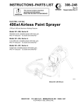
OWNER’S MANUAL
820–173 Rev F
Supercedes Rev D and PCN E
This manual contains important
warnings and information.
READ AND RETAIN FOR REFERENCE
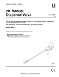
SUPER NOVA SP
ELECTRIC, AIRLESS PAINT SPRAYER
2750 psi (195 bar) Maximum Working Pressure
Model 820–169, Series B
Complete sprayer with hose, gun,
RAC IV DripLess Tip Guard and SwitchTip
Model 820–248, Series A
Upright cart; complete sprayer with hose, gun,
RAC IV DripLess Tip Guard and SwitchTip
05169
Model 820–169 Shown
The SHERWIN-WILLIAMS COMPANY, CLEVELAND, OHIO 44115
COPYRIGHT 1992, GRACO INC.
Table of Contents
Warnings . . . . . . . . . . . . . . . . . . . . . . . . . . . . . . . . . . . . . . 2
Component Identification and Function . . . . . . . . . . . . 5
Setup . . . . . . . . . . . . . . . . . . . . . . . . . . . . . . . . . . . . . . . . . 6
Operation . . . . . . . . . . . . . . . . . . . . . . . . . . . . . . . . . . . . . 7
Startup . . . . . . . . . . . . . . . . . . . . . . . . . . . . . . . . . . . . . . . 9
Shutdown and Care . . . . . . . . . . . . . . . . . . . . . . . . . . . 11
Flushing . . . . . . . . . . . . . . . . . . . . . . . . . . . . . . . . . . . . . 12
Troubleshooting . . . . . . . . . . . . . . . . . . . . . . . . . . . . . . . 13
Motor Test . . . . . . . . . . . . . . . . . . . . . . . . . . . . . . . . . . . . 17
General Repair Information . . . . . . . . . . . . . . . . . . . . . 18
Motor Brush . . . . . . . . . . . . . . . . . . . . . . . . . . . . . . . . . . 19
Displacement Pump Repair . . . . . . . . . . . . . . . . . . . . . 21
Motor . . . . . . . . . . . . . . . . . . . . . . . . . . . . . . . . . . . . . . . . 25
Motor Start Board . . . . . . . . . . . . . . . . . . . . . . . . . . . . . 26
Power Supply Cord . . . . . . . . . . . . . . . . . . . . . . . . . . . . 26
ON/OFF Switch . . . . . . . . . . . . . . . . . . . . . . . . . . . . . . .
Drive Housing, Connecting Rod, Crankshaft . . . . . .
Pressure Control . . . . . . . . . . . . . . . . . . . . . . . . . . . . . .
Pressure Transducer . . . . . . . . . . . . . . . . . . . . . . . . . .
Suction Hose . . . . . . . . . . . . . . . . . . . . . . . . . . . . . . . . .
Drain Valve . . . . . . . . . . . . . . . . . . . . . . . . . . . . . . . . . . .
Displacement Pump Parts Drawing and List . . . . . .
Model 820–169 Sprayer Parts Drawing . . . . . . . . . .
Model 820–169 Sprayer Parts List . . . . . . . . . . . . . . .
Model 820–248 Sprayer Parts Drawing . . . . . . . . . .
Model 820–248 Sprayer Parts List . . . . . . . . . . . . . . .
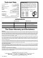
Technical Data . . . . . . . . . . . . . . . . . . . . . . . . . . . . . . . .
Dimensions . . . . . . . . . . . . . . . . . . . . . . . . . . . . . . . . . . .
Graco Warranty and Disclaimers . . . . . . . . . . . . . . . .
26
27
29
30
31
32
33
34
35
36
37
40
40
40
Symbols
Warning Symbol
Caution Symbol
WARNING
CAUTION
his symbol alerts you to the possibility of serious
injury or death if you do not follow the instructions.
This symbol alerts you to the possibility of damage to
or destruction of equipment if you do not follow the
instructions.
WARNING
WARNING
FIRE AND EXPLOSION HAZARD
Improper grounding, poor ventilation, open flames or sparks can cause a hazardous condition and
result in a fire or explosion and serious injury.
If there is any static sparking or you feel an electric shock while using this equipment, stop
spraying immediately. Do not use the equipment until you identify and correct the problem.
Provide fresh air ventilation to avoid the buildup of flammable fumes from solvents or the fluid
being sprayed.
Keep the spray area free of debris, including solvent, rags, and gasoline.
Electrically disconnect all equipment in the spray area.
Extinguish all open flames or pilot lights in the spray area.
Do not smoke in the spray area.
Do not turn on or off any light switch in the spray area while operating or if fumes are present.
Do not operate a gasoline engine in the spray area.
WARNING
WARNING
INJECTION HAZARD
Spray from the gun, leaks or ruptured components can inject fluid into your body and cause extremely serious injury, including the need for amputation. Fluid splashed in the eyes or on the skin
can also cause serious injury.
Fluid injected into the skin is a serious injury. The injury may look like just a cut, but it is a serious
injury. Get immediate medical attention.
Do not point the gun at anyone or at any part of the body.
Do not put your hand or fingers over the spray tip.
Do not stop or deflect leaks with your hand, body, glove or rag.
Do not “blow back” fluid; this is not an air spray system.
Always have the tip guard and the trigger guard on the gun when spraying.
Check the gun diffuser operation weekly. Refer to the gun manual.
Be sure the gun trigger safety operates before spraying.
Lock the gun trigger safety when you stop spraying.
Follow the Pressure Relief Procedure on page 9 if the spray tip clogs and before cleaning,
checking or servicing the equipment.
Tighten all fluid connections before operating the equipment.
Check the hoses, tubes, and couplings daily. Replace worn or damaged parts immediately. Do
not repair high pressure couplings; you must replace the entire hose.
Fluid hoses must have spring guards on both ends, to help protect them from rupture caused by
kinks or bends near the couplings.
TOXIC FLUID HAZARD
Hazardous fluid or toxic fumes can cause serious injury or death if splashed in the eyes or on the
skin, inhaled, or swallowed.
Know the specific hazards of the fluid you are using.
Store hazardous fluid in an approved container. Dispose of hazardous fluid according to all local,
state and national guidelines.
Always wear protective eyewear, gloves, clothing and respirator as recommended by the fluid
and solvent manufacturer.
MOVING PARTS HAZARD
Moving parts can pinch or amputate your fingers.
Keep clear of all moving parts when starting or operating the pump.
Before servicing the equipment, follow the Pressure Relief Procedure on page 9 to prevent the
equipment from starting unexpectedly.
WARNING
WARNING
EQUIPMENT MISUSE HAZARD
Equipment misuse can cause the equipment to rupture or malfunction and result in serious injury.
INSTRUCTIONS
This equipment is for professional use only.
Read all instruction manuals, tags, and labels before operating the equipment.
Use the equipment only for its intended purpose. If you are not sure, call Graco Technical Assistance at 1–800–543–0339.
Do not alter or modify this equipment.
Check equipment daily. Repair or replace worn or damaged parts immediately.
Do not exceed the maximum working pressure of the lowest rated system component. Refer to
the Technical Data on page 40 for the maximum working pressure of this equipment.
Use fluids and solvents which are compatible with the equipment wetted parts. Refer to the Technical Data section of all equipment manuals. Read the fluid and solvent manufacturer’s warnings.
Do not use 1,1,1–trichloroethane, methylene chloride, other halogenated hydrocarbon solvents or
fluids containing such solvents in pressurized aluminum equipment. Such use could result in a
chemical reaction, with the possibility of explosion.
Do not use hoses to pull equipment.
Route hoses away from traffic areas, sharp edges, moving parts, and hot surfaces. Do not expose Graco hoses to temperatures above 82C (180F) or below –40C (–40F).
Do not lift pressurized equipment.
Comply with all applicable local, state, and national fire, electrical, and safety regulations.
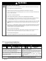
NOTE: This is an example of the DANGER label on
your sprayer. This label is available in other
languages, free of charge. See page 40 to order.
FIRE AND
EXPLOSION HAZARD
Spray painting, flushing or cleaning equipment with flammable liquids in confined areas can result in fire or explosion.
Use outdoors or in extremely well ventilated areas. Ground equipment, hoses, containers and objects being sprayed.
Avoid all ignition sources such as static electricity from plastic drop
cloths, open flames such as pilot lights, hot objects such as cigarettes, arcs from connecting or disconnecting power cords or turning light switches on and off.
Failure to follow this warning can result in death or serious injury.
SKIN INJECTION
HAZARD
Liquids can be injected into the body by high pressure airless spray
or leaks – especially hose leaks.
Keep body clear of the nozzle. Never stop leaks with any part of the
body. Drain all pressure before removing parts.Avoid accidental triggering of gun by always setting safety latch when not spraying.
Never spray without a tip guard.
In case of accidental skin injection, seek immediate
“Surgical Treatment”.
Failure to follow this warning can result in amputation or serious
injury.
READ AND UNDERSTAND ALL LABELS AND INSTRUCTION MANUALS BEFORE USE
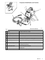
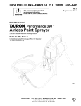
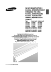
Component Identification and Function
N
B
C
H
A
K
E
G
L
F
M
D
J
Model 820–169 Shown
02834B
Fig. 1
A
Motor
DC motor, 120 Vac, 15A, 1 phase
B
Drive Assembly
Transfers power from DC motor to the displacement pump
C
Pressure Adjusting Knob
Controls fluid outlet pressure
D
ON/OFF Switch
Power switch that controls 120 Vac power to sprayer
E
Fluid Outlet
Hose and spray gun is connected here
F
Displacement Pump
Pressurizes fluid to be sprayed through spray gun
G
50 ft (15 m) Main Hose
1/4 in. ID, grounded, nylon hose with spring guards on both ends
H
RAC IV Tip Guard
Reverse-A-Clean (RAC) tip guard reduces the risk of fluid injection injury
J
Contractor Gun
High pressure spray gun with gun safety latch
K
RAC IV Switch Tip
RAC switch tip atomizes fluid and removes clogs from spray tip without
removing tip from spray gun
L
Pressure Drain Valve
Relieves fluid pressure when open
M
Pressure Control
Controls motor to maintain fluid pressure. Works with pressure
adjusting knob.
N
Spray Gun Safety Latch
Inhibits accidental triggering of spray gun
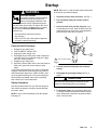
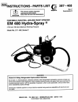
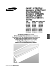
Setup
2. Fill the wet–cup (102). Pry off the wet-cup seal.
Fill the cup 1/3 full with Graco Throat Seal Liquid
(TSL), supplied. Install the wet-cup seal.
WARNING
If you supply your own hoses and spray gun, be
sure the hoses are electrically conductive, that the
gun has a tip guard, and that each part is rated for
at least 2750 psi (195 bar) Working Pressure. This
is to reduce the risk of serious injury caused by
static sparking, fluid injection or over-pressurization
and rupture of the hose or gun.
3. Plug in the sprayer. Be sure the ON/OFF switch
(52) is OFF. Plug the cord into a 15A grounded
outlet at least 20 feet away from the spray area. A
12 AWG 150 ft (45 m) grounded extension cord
may be used.
WARNING
CAUTION
FIRE AND EXPLOSION HAZARD
Proper electrical grounding is essential
to reduce the risk of fire or explosion
which can result in serious injury and
property damage. Also read FIRE OR
EXPLOSION HAZARD on page 2.
To avoid damaging the pressure control, which
may result in poor equipment performance and
component damage, follow these precautions:
1. Always use a nylon spray hose at least 50 ft.
(15 m) long.
4. Flush the pump to remove the lightweight oil
which was left in to protect pump parts after factory testing. See page 12.
2. Never use a wire braid hose as it is too rigid to
act as a pulsation dampener.
3. Never install any shutoff device between the
filter and the hose. See Fig. 2.
5. Prepare the paint according to the manufactuers’s recommendations. Remove any paint skin.
Strain the paint through a fine nylon mesh bag
(available at most paint dealers) to remove particles that could clog the spray tip. This is an important step toward trouble-free paint spraying.
1. Connect the hose (74) and gun (67) and screw it
onto the outlet nipple (28). Don’t use thread
sealant, and don’t install the spray tip yet!
1
1/4 npsm(m) fluid outlet
2
Do not install any shutoff device here
3
Rotate clockwise to increase pressure
4
Shown in closed or spray position
5
Fill 1/3 full with TSL
32
33
3
2
1
64
28
74
52
4
102
5
67
Model 820–169 Shown
Fig. 2
02834B
Operation
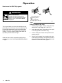
How to use the gun trigger safety
1
Open or drain, position
When engaged, the gun safety latch prevents the gun
from accidental triggering. See Fig. 3.
2
Closed, or spray position
WARNING
INJECTION HAZARD
If the gun still sprays when the gun trigger safety is locked, repair the gun. See
manual 307–614, supplied.
1
2
1
Gun safety latch
shown engaged
2
Gun safety latch
shown disengaged
05170
Fig. 4
How to use the pressure control.
The pressure control controls the motor operation so
the sprayer maintains constant fluid pressure at the
pump outlet. Turn the pressure control knob fully counterclockwise to obtain the minimum setting. Turn the
knob clockwise to increase pressure. See Fig. 5.
1
2
Fig. 3
01020A
How to use the pressure drain valve.
Use the pressure drain valve to relieve fluid pressure
from the pump and to help prime the pump. If the valve
senses an over pressure condition, it opens automatically to relieve fluid pressure. If this happens, stop
spraying immediately, shut off and unplug the sprayer.
Determine the cause of the problem and correct it before operating the sprayer again. Refer also to the
Troubleshooting, page 13. See Fig. 4.
05171
Fig. 5
Operation
How to use the RAC IV tip guard.
WARNING
INJECTION HAZARD
To reduce the risk of serious injury,
whenever you are instructed to relieve
pressure, follow the Pressure Relief
Procedure on page 9.
1
1
Tip handle shown in
spraying position.
2
Turn handle 180,
trigger gun to clear clog
Fig. 6
2
04647
How to remove a tip clog.
The tip guard alerts you to the risk and helps prevent
placing any part of the body close to the spray tip. The
tip guard also adjusts the vertical or horizontal spray
pattern. See Fig. 8. The tip guard holds a reversing
spray tip. The tip is in the spraying position when the
tip handle points forward. See Fig. 6.
Clean the front of the tip frequently during the day’s
operation. First, follow the Pressure Relief Procedure
on page 9.
1. Release the gun trigger. Lock the safety latch. Rotate the RAC IV tip handle 180. See Fig. 6.
2. Unlock the safety latch. Trigger the gun into a pail
or onto the ground to remove the clog.
3. Lock the safety latch. Rotate the tip handle to the
spraying position.
4. If the tip is still clogged, lock the safety latch, shut
off and unplug the sprayer, and open the pressure
drain valve to relieve pressure. Clean the spray tip
as shown in manual 307–848, supplied.
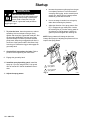
Startup
WARNING
INJECTION HAZARD
The system pressure must be manually
relieved to prevent the system from
starting or spraying accidentally. Fluid
under high pressure can be injected through the
skin and cause serious injury. To reduce the risk of
an injury from injection, splashing fluid, or moving
parts, follow the Pressure Relief Procedure
whenever you:
are instructed to relieve the pressure,
stop spraying,
check or service any of the system equipment,
or install or clean the spray tip.
NOTE: Refer to Fig. 2 and the other figures referenced
in the text as you start the sprayer.
1. Open the pressure drain valve (42). See Fig. 7.
2. Don’t install the spray tip until the pump is
primed!
3. Put the suction hose (32) into the paint. If you
are pumping from a pail, push the drain hose (33)
down below the top of the pail to avoid splashing
paint when the drain valve is opened.
Pressure Relief Procedure
1.
2.
3.
4.
Engage the gun safety latch.
Turn the ON/OFF switch to OFF.
Unplug the power supply cord.
Disengage the gun safety latch. Hold a metal part
of the gun firmly to a grounded metal pail. Trigger
the gun to relieve pressure.
5. Engage the gun safety latch.
6. Open the pressure drain valve. Leave the pressure
drain valve open until you are ready to spray
again.
If you suspect that the spray tip or hose is completely
clogged, or that pressure has not been fully relieved
after following the steps above, VERY SLOWLY loosen the tip guard retaining nut or hose end coupling to
relieve pressure gradually, then loosen completely.
Now clear the tip or hose obstruction.
Startup Procedure
Use this procedure each time you start the sprayer to
help ensure the sprayer is ready to operate and that
you start it safely.
NOTE: If this is a first-time startup, flush the sprayer.
See page 12.
42 1
1
Open or drain, position
01021A
Fig. 7
4. Turn the pressure knob (64) to the minimum
setting.
5. Disengage the gun trigger safety. See Fig. 3,
page 7.
CAUTION
Do not run the sprayer dry for more than 30 seconds to avoid damaging the pump packings.
6. To prime the pump, turn the sprayer switch (52)
on. Slowly increase the pressure until the sprayer
starts. When fluid comes from the pressure drain
valve, close the valve.
Startup
a. Increase the pressure until spray from the gun
is completely atomized. To avoid excessive
overspray and fogging, and to extend tip and
sprayer life, always use the lowest pressure
needed to get the desired results.
WARNING
FIRE AND EXPLOSION HAZARD
To reduce the risk of static sparking and
splashing when priming or flushing the
system, hold a metal part of the gun
firmly to the side of a grounded metal pail before
triggering the gun.
b. If more coverage is needed, use a larger tip
rather than increasing the pressure.
c.
7. To prime the hose, lower the pressure to reduce
splashing. Hold a metal part of the gun firmly
against and aimed into a grounded metal pail. See
the preceding WARNING. Hold the gun trigger
open and slowly increase the pressure until the
pump starts. Keep the gun triggered until all air is
forced out of the system and the fluid flows freely
from the gun. Release the trigger and engage the
gun safety latch.
Adjust the direction of the spray pattern. See
Fig. 8. Engage the gun safety latch. Loosen
the retaining nut (A). Position the tip guard for
a horizontal or vertical pattern. Hold the tip
guard in place and tighten the retaining nut.
NOTE: Spray patterns will change as tips wear.
Change the spray tip if adjusting the pressure will not
improve the spray pattern.
A
8. Check all fluid connections for leaks. Relieve
pressure before tightening the connections.
2
9. Engage the gun safety latch.
10. Install the spray tip and tip guard. Install the
spray tip. If you are using the RAC IV tip guard,
refer to manual 307–848 for installation instructions.
11. Adjust the spray pattern
1
1
For a vertical
spray pattern
2
For a horizontal
spray pattern
Fig. 8
01025A
Shutdown and Care
WARNING
WARNING
INJECTION HAZARD
To reduce the risk of serious injury,
whenever you are instructed to relieve
pressure, follow the Pressure Relief
Procedure on page 9.
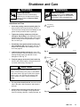
Shutdown and Care
1. Check the packing nut/wet-cup daily (102). Relieve pressure first. Keep the wet-cup 1/3 full of
TSL at all times to help prevent fluid buildup on the
piston rod and premature wear of packings.
INJECTION HAZARD
See the warning section INJECTION
HAZARD on page 3 for information on
the hazard of using damaged hoses.
Turn packing
nut clockwise to
tighten
1
2. Tighten the packing nut/wet-cup (102) just
enough to stop leakage. Over-tightening causes
binding and excessive packing wear. Use a round
punch or brass rod and a light hammer to adjust
the nut. See Fig. 9.
3. Periodically clean paint residue from the pressure transducer (29) vent hole area. See Fig. 10.
Replace the transducer when leakage is excessive. See page 30.
4. Lubricate the bearing housing after every 100
hours of operation. Remove the front cover. Fill the
bearing housing cavity (A) with SAE 10 nondetergent oil. See Fig. 10.
5. Flush the sprayer at the end of each work day
and fill it with mineral spirits to help prevent pump
corrosion and freezing. See page 12.
1
102
05117A
Fig. 9
1
Vent hole
29
1
A
CAUTION
To prevent pump corrosion, and to reduce the
chance of fluid freezing in the pump in cold weather,
never leave water or any type of paint in the sprayer
when it is not in use. Freezing can seriously damage the sprayer or result in a loss of pressure or
stalling.
6. For very short shutoff periods, leave the suction
tube in the paint, relieve pressure, and clean the
spray tip.
7. Coil the hose and hang it on a hose rack when
storing it, even for overnight, to help protect the
hose from kinking, abrasion, coupling damage, etc.
05172
Fig. 10
Flushing
When to Flush
1. Before using a new sprayer: flush out the oil
which was left in to protect pump parts.
Before using water-base paint: flush with mineral spirits followed by soapy water, and then a
clean water flush.
Before using oil-base paint: flush with mineral
spirits only.
2. Changing colors: flush with a compatible solvent
such as mineral spirits or water.
3. Changing from water-base to oil-base paint:
flush with warm, soapy water, and then mineral
spirits.
4. Changing from oil-base to water-base paint:
flush with mineral spirits, then warm, soapy water,
and then a clean water flush.
5. Storage after using water-base paint: flush with
water and then mineral spirits. Leave the system
filled with mineral spirits. Relieve pressure. Leave
the drain valve open.
Storage after using oil-base paint: flush with
mineral spirits. Relieve pressure. Leave the drain
valve open.
CAUTION
Never allow water to freeze in the pressure control.
Doing so prevents the sprayer from being started
and may cause serious damage. Push the water out
with mineral spirits.
6. Startup after storage. Before using water-base
paint, flush out the mineral spirits with soapy water
and then clean water. When using oil-base paint,
flush out the mineral spirits with the paint.
How to Flush
1. Follow the Pressure Relief Procedure on
page 9.
2. Remove the spray tip and clean it separately. Remove the filter screen and then reinstall the bowl,
hand tight, without the screen. Clean the screen
separately.
3. Pour one-half gallon (2 liters) of compatible solvent
into a grounded metal flushing pail. Put the suction
hose in the pail.
4. Open the pressure drain valve. See Fig. 4, page
7.
5. To save the paint still in the pump and hose,
follow Step 6, except put the drain tube in the paint
pail. When solvent appears, close the drain valve.
Put the drain tube in the flushing pail. Trigger the
gun into the paint pail. When solvent appears, release the trigger. Continue with Step 6.
WARNING
FIRE AND EXPLOSION HAZARD
To reduce static sparking and splashing,
always remove the spray tip from the
gun, and hold a metal part of the gun
firmly to the side of a grounded metal pail when
flushing.
6. Lower the pressure setting. Turn on the sprayer.
Maintaining metal-to-metal contact, trigger the gun
into the flushing pail. Slowly increase the sprayer
pressure until the pump starts. Keep the gun triggered until the solvent flows freely from the gun.
Circulate the solvent to thoroughly clean the sprayer. Release the gun trigger. Engage the gun trigger
safety.
7. Open the drain valve and circulate the solvent
through the drain tube to thoroughly clean it. Close
the drain valve.
8. Remove the suction hose from the pail. Disengage
the gun trigger safety. Trigger the gun and run the
pump a few seconds to push air into the hose. Do
not run the pump dry for more than 30 seconds to
avoid damaging the pump packings! Relieve pressure.
9. Remove and clean the inlet strainer. Wipe paint off
the suction hose and drain tube.
10. Refer to When To Flush, Step 1 again. Relieve
pressure.
11. Leave the drain valve open until you use the
sprayer again.
Troubleshooting
WARNING
INJECTION HAZARD
To reduce the risk of serious injury, whenever you are instructed to relieve pressure, follow the
Pressure Relief Procedure on page 9.
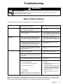
Basic Problem Solving
Check everything in the troubleshooting table before disassembling the sprayer.
TYPE OF PROBLEM
WHAT TO CHECK
If check is OK, go to next check
WHAT TO DO
When check is not OK, refer to this column
Fluid pressure
1. Check pressure control knob setting. The pump
won’t develop much pressure if it is at minimum
setting (fully counterclockwise).
1. Slowly increase pressure setting to see if
motor starts.
2. Check for a clogged spray tip or fluid filter, if
used. See page 8.
2. If tip is still clogged, relieve pressure; refer to separate gun or tip instruction manual for tip cleaning. Clean or replace filter
element. See manual 308–429.
1. Check for frozen or hardened paint in pump
(20). Using a screwdriver, carefully try to rotate
fan at back of motor by hand. See page 17.
1. Thaw. Plug in sprayer and turn on.
Slowly increase pressure setting to see if
motor starts. If it doesn’t, see NOTE, below.
Mechanical
2. Check pump connecting rod pin (17). It must be 2. Push pin into place and secure with
completely pushed into connecting rod (15),
spring retainer.
and retaining spring (18) must be firmly in connecting rod groove. See Fig. 17, page 21.
Electrical
3. Check for motor damage. Remove drive housing assembly (11). See page 27. Try to rotate
motor fan by hand.
3. Replace motor (4) if fan won’t turn. See
page 25.
1. Check electrical supply with volt meter. Meter
should read 105–125 VAC.
1. Reset building circuit breaker; replace
building fuse. Try another outlet.
2. Check extension cord for visible damage. Use
a volt meter or test lamp at extension cord outlet to check.
2. Replace extension cord.
3. Check sprayer power supply cord (50) for vis3. Replace power supply cord.
ible damage such as broken insulation or wires.
See page 26.
4. Check motor brushes for the following:
a. Loose terminal screws.
b. Broken or misaligned brush springs.
c. Brushes binding in holders.
d. Broken leads.
e. Worn brushes.
NOTE: The brushes do not wear at same rate
on both sides of motor. Check both brushes.
4. Refer to page 19.
a. Tighten.
b. Replace broken spring and/or align
spring with brush
c. Clean brush holders. Remove carbon
with small cleaning brush. Align brush
leads with slot in brush holder to assure free vertical brush movement.
d. Replace brushes
e. Replace brushes if less than 0.5 in.
long.
NOTE: Thaw sprayer if water or water–based paint has frozen in it, due to exposure to low temperatures, by placing in a warm
area. Do not try to start sprayer until completely thawed or damage to motor and/or start board may occur. If paint hardened
(dried) in sprayer, the pump packings (page 21) and/or pressure transducer (page 30) must be replaced.
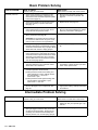
Basic Problem Solving
TYPE OF PROBLEM
WHAT TO CHECK
If check is OK, go to next check
WHAT TO DO
When check is not OK, refer to this column
Electrical (continued)
5. Check motor armature commutator for burn
spots, gouges and extreme roughness. Remove motor cover and brush inspection plates
to check. See page 19.
5. Remove motor and have motor shop
resurface commutator if possible. See
page 25.
6. Check motor armature for shorts using armature tester (growler) or perform motor test.
See page 17.
6. Replace motor. See page 25.
7. Check leads from pressure control and motor to 7. Replace loose terminals; crimp to leads.
motor start board (47) to be sure they are seBe sure male terminal blades are straight
curely fastened and properly mated.
and firmly connected to mating part.
8. Check motor start board (47) by substituting
with a good board. See page 26.
8. Replace board. See page 26.
CAUTION: Do not perform this check until motor armature is determined to be good. A bad
motor armature can burn out a good board.
9. Check power supply cord (50). Disconnect
9. Replace power supply cord. See page
black and white power cord terminals; connect
26.
volt meter to these leads. Plug in sprayer. Meter
should read 105–125VAC. Unplug sprayer.
10. Check ON/OFF switch (52). Disconnect the
motor start board (47) and switch and connect
volt meter between exposed terminal on switch
and power cord’s white wire. Plug in sprayer
and turn ON. Meter should read 105–125VAC
Turn off and unplug sprayer.
10. Replace ON/OFF switch. See page 26.
11. Check motor thermal cutout switch. Connect
ohmmeter between motor’s red leads. Meter
should read 1 ohm maximum.
11. Allow motor to cool. Correct cause of
overheating. If switch remains open after
motor cools, replace motor.
12. Remove pressure control (64) and check microswitch operation with ohmmeter:
(1) With pressure knob at lowest setting and
stem pushed into control, readings should
be: white & black = 1 ohm max.
white & red = open.
(2) With pressure knob at highest setting,readings should be: white & black = open;
white & red = 1 ohm max.
12. Replace pressure control. See page 29.
13. Check pressure transducer (29) for hardened
paint or damaged or worn components. See
page 30.
13. Replace transducer. See page 30. Thorough system flushing will help extend life
of transducer.
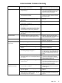
Intermediate Problem Solving
TYPE OF PROBLEM
WHAT TO CHECK
If check is OK, go to next check
WHAT TO DO
When check is not OK refer to this column
Low output
1. Check for worn spray tip.
1. Follow Pressure Relief Procedure then
replace tip. See your separate gun or tip
manual.
2. Be sure pump does not continue to stroke
when gun trigger is released. Plug in and turn
on sprayer. Prime with paint. Trigger gun momentarily, then release and lock safety latch.
Relieve pressure, turn off and unplug sprayer.
2. Service pump. See page 21.
Intermediate Problem Solving
TYPE OF PROBLEM
WHAT TO CHECK
If check is OK, go to next check
WHAT TO DO
When check is not OK, refer to this column
Low output (continued)
3. Release gun trigger. Observe resting position of 3. If pump consistently comes to rest with
pump rod (107).
rod (107) fully extended, the piston packings and/or piston valve may be worn.
Service the pump. See page 21.
4. Check electrical supply with volt meter. Meter
should read 105–125VAC.
4. Reset building circuit breaker; replace
building fuse. Repair electrical outlet or
try another outlet.
5. Check extension cord size and length; must be
at least 12 gauge wire and less than 150 ft
(45 m) long.
5. Replace with a correct, grounded extension cord.
6. Check motor brushes. See Electrical – What To
Check, item 4, on page 13.
6. See page 19.
7. Check motor start board (47) by substituting
with a good board.
7. Replace board. See page 26.
CAUTION: Do not perform this check until motor armature is determined to be good. A bad
motor armature can burn out a good board.
8. Check motor armature for shorts by using an
armature tester (growler) or perform motor test.
See page 17.
8. Replace motor. See page 25.
Drain valve leaks
1. Check drain valve for correct torque and/or
worn parts. Check for debris trapped on seat.
9. Tighten to 185 in–lb (21 N.m). Clean
valve and replace with new gasket (42a)
and sealant (42d). See page 32.
Transducer leaks
1. Slight leakage from transducer is normal.
1. Periodically remove residue from its cylinder port. See page 30.
No output: motor runs and
pump strokes
1. Check paint supply.
1. Refill and reprime pump.
2. Check for clogged intake strainer.
2. Remove and clean, then reinstall.
3. Check for loose suction tube or fittings. See
page 31.
3. Tighten; use thread sealant on npt
threads of adapter (38).
4. Check to see if intake valve ball and piston ball
are seating properly. See page 21.
4. Remove intake valve and clean. Check
ball and seat for nicks; replace as needed. See page 21. Strain paint before using to remove particles that could clog
pump.
5. Check for leaking around throat packing nut
which may indicate worn or damaged packings.
See page 21.
5. Replace packings. See page 21. Also
check piston valve seat for hardened
paint or nicks and replace if necessary.
Tighten packing nut/wet-cup.
6. Release gun trigger. Observe resting position of 6. If pump consistently comes to rest with
pump rod (107).
rod (107) fully extended, the piston packings and/or piston valve may be worn.
Service the pump. See page 21.
No output: motor runs but
pump does not stroke
1. Check displacement pump connecting rod pin
(17). See Fig. 17, page 21.
1. Replace pin if missing. Be sure retainer
spring (18) is fully in groove all around
connecting rod.
7. Check connecting rod assembly (15) for damage. See page 27.
7. Replace connecting rod assembly. See
page 27.
8. Be sure crank in drive housing rotates; plug in
sprayer and turn on briefly to check. Turn off
and unplug sprayer. See page 27.
8. Check drive housing assembly for
damage and replace if necessary. See
page 27.
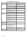
Intermediate Problem Solving
TYPE OF PROBLEM
WHAT TO CHECK
If check is OK, go to next check
WHAT TO DO
When check is not OK, refer to this column
Spray Pattern Variations
1. Spray tip worn beyond sprayer pressure capability.
1. Replace spray tip.
NOTE: A smaller size tip will provide
longer life.
2. Check transducer (29) for wear or damage.
2. Replace transducer. See page 30.
3. Check pressure control (64) for smooth operation.
3. Replace pressure control. See page 29.
4. Check Low output section, page 15.
Motor Is Hot and Runs
Intermittently
1. Determine if sprayer was operated at high pres- 1. Decrease pressure setting or increase tip
size.
sure with small tips, which causes excessive
heat build up.
2. Be sure ambient temperature where sprayer is
located is no more than 90F (32C) and
sprayer is not located in direct sun.
2. Move sprayer to shaded, cooler area if
possible.
3. Check motor.
3. Replace motor. See page 25.
Building Circuit Breaker 1. Check all electrical wiring for damaged insulation, and all terminals for loose fit or damage.
Opens As Soon As Sprayer
Also check wires between pressure control and
Switch Is Turned On.
motor. See page 25.
1. Repair or replace any damaged wiring or
terminals. Securely reconnect all wires.
2. Check for missing motor brush inspection plate
gasket (see page 17), bent terminal forks or
other metal to metal contact points which could
cause a short.
2. Correct faulty conditions.
3. Check motor armature for shorts. Use an armature tester (growler) or perform motor test. See
page 17. Inspect windings for burns.
3. Replace motor. See page 25.
4. Check motor start board (47) by substituting
with a good board.
4. Replace board. See page 26.
CAUTION: Do not perform this check until
motor armature is determined to be good. A
bad motor armature can burn out a good board.
Circuit breaker opens after 1. Check ‘Basic Problems – Electrical’ on page
13.
sprayer operates for 5 to 10
minutes.
Building circuit breaker
1. Check ON/OFF switch (52). Be sure sprayer is
unplugged! Disconnect wires from switch.
opens as soon as sprayer
Check switch with ohmmeter. The reading
is plugged into outlet and
should be infinity with ON/OFF switch OFF,
sprayer is NOT turned on.
and zero with switch ON.
1. Replace ON/OFF switch. See page 26.
CAUTION: A short in motor circuit can damage
switch and or motor start board (47).
2. Check electrical supply with volt meter. Meter
should read 105–125 VAC.
Unit will not run on generator but does run on AC
power
2. If voltage is too high, do not operate
sprayer until corrected.
Check the generator’s peak voltage. This sprayer will Use AC power or a different generator
not run if the peak voltage is above 190V.
Motor Test
WARNING
INJECTION HAZARD
To reduce the risk of serious injury,
whenever you are instructed to relieve
pressure, follow the Pressure Relief
Procedure on page 9.
For checking armature, motor winding and brush electrical continuity.
B
Setup
A
Remove the drive housing. See page 27. This is to
ensure that any resistance you notice in the armature
test is due to the motor and not to worn gears in the
drive housing.
Remove the motor brush inspection covers (A). See
Fig. 11.
Remove the junction box screws (56). Lower the junction box. Disconnect the two leads (C) from the motor
to the board (47). See Fig. 12.
Armature Short Circuit Test
Model 820–169 Shown
Fig. 11
02835B
Remove the fan cover (B). See Fig. 11.
Spin the motor fan by hand. If there are no shorts, the
motor will coast two or three revolutions before coming
to a complete stop. If the motor does not spin freely,
the armature is shorted and the motor must be replaced. See page 25.
MOTOR
Armature, Brushes, and Motor Wiring
Open Circuit Test (Continuity)
Connect the two black motor leads together with a test
lead. Turn the motor fan by hand at about two revolutions per second.
When turning the fan on a DC motor, normally you
sense an even, pulsing resistance. If there is irregular
turning resistance, or no turning resistance, check and
repair the following as needed: broken brush springs,
brush leads, motor leads; loose brush terminal screws
or motor lead terminals; worn brushes. See page 19.
BLACK/
WHITE
BLACK
C
59
RED
56
47
If there is still uneven or no turning resistance, replace
the motor. See page 25.
Fig. 12
04720
General Repair Information
WARNING
INJECTION HAZARD
To reduce the risk of serious injury,
whenever you are instructed to relieve
pressure, follow the Pressure Relief
Procedure on page 9.
Tool List
HOT SURFACE HAZARD
During operation, the motor and drive
housing become very hot and could burn
your skin if touched. Flammable materials spilled on the hot, bare motor could cause a fire
or explosion
CAUTION
These are the tools required to service all parts of the
sprayer.
3/16” Allen wrench: gear housing, legs, handle
3/8” Allen wrench: pump manifold
#1 Phillips screwdriver: junction box,
pressure control, front cover
3/8” socket wrench: motor mount
5/8” socket wrench: drain valve, outlet fittings,
on/off switch boot, piston
13/16” socket wrench: drain valve
1-1/4” socket wrench: pump inlet valve
1/2” open end wrench: pump rod
11/16” open end wrench: piston jam nut
15/16” open end wrench: flats of inlet tube
1-3/4” open end wrench: pump jam nut
5/64” drive pin: drain valve pin
3” needle nose pliers: wiring, on/off switch
Hammer & punch: packing nut
Torque wrenches: various fasteners
WARNING
MOVING PARTS HAZARD
To reduce the risk of serious injury, including electric shock, DO NOT touch
any moving parts or electrical parts with
your fingers or a tool while inspecting the repair.
Shut off the sprayer and unplug it as soon as you
complete the inspection.
Reinstall all covers, gaskets, screws and washers
before operating the sprayer.
WARNING
To reduce the risk of a pressure control malfunction, be sure to properly mate connectors, and
never pull on a wire to disconnect it. Pulling on a
wire could loosen the connector from the wire.
1. When disconnecting wires in the junction box
assembly, use needle nose pliers to separate mating connectors.
2. When reconnecting the wires, be sure the flat
blade of the insulated male connector is centered
in the wrap–around blade of the female
connector.
CAUTION
Improper wire routing can result in poor sprayer
performance or damage to the pressure control.
3. Route wires carefully through the drive housing
and motor. Avoid pinching the wires between the
junction box and the motor or pressure control.
4. Keep all screws, nuts, washers, gaskets, and
electrical fittings removed during repair procedures. These parts are not normally provided with
replacement assemblies.
5. Test your repair before regular operation to be
sure the problem is corrected.
6. If the sprayer does not operate properly, verify
that everything was done correctly. Also refer to
the Troubleshooting Guide, pages 13–17, to help
identify other possible problems and solutions.
Motor Brushes
NOTE: Replace brushes when worn to about 0.5 in.
(12.5 mm). Always check both brushes. Brush Repair
Kit 821–022, which includes spring clip 821–061, is
available for motors manufactured by Pacific Scientific.
NOTE: Replacement brushes may last only half as
long as the original ones. To maximize brush life, break
in new brushes by operating the sprayer for at least
one hour with no load (remove the pump connecting
rod pin).
1
Motor lead; do not disconnect
2
Minimum 0.5” (12.5 mm)
3
Included in Brush Repair
Kit 821–022
2
3
1
H C
G
F
B
WARNING
INJECTION HAZARD
To reduce the risk of serious injury,
whenever you are instructed to relieve
pressure, follow the Pressure Relief
Procedure on page 9.
1. Remove both inspection covers (A) and their gaskets. See Fig 13.
E
03881
D
Fig. 14
4. Inspect the commutator for excessive pitting, burning or gouging. A black color on the commutator is
normal. Have the commutator resurfaced by a
qualified motor repair shop if the brushes seem to
wear too fast or arc excessively. See Step 9.d.,
also.
5. Repeat for the other side.
NOTE: The motor brushes on the other side are
upside down.
6. Place a new brush (C) in the holder (B) so the
ramp (H) faces the spring. See Fig. 16.
1
F
G
A
C
Fig. 13
05173
2. Push in the spring clip (F) and release its hook (G)
from the brush holder (B). Pull out the spring clip.
See Fig 14.
3. Slide off the brush lead terminal (E) off the blade
connector. Remove the old brush (C). See Fig 14.
Fig. 15
E
03881
7. Holding the spring clip (F) at a slight angle, slide
the spring clip into the brush holder and hook it
over the end of the holder. See Fig. 15. Pull on the
spring clip to be sure it stays in place. Connect the
brush lead to the blade connector (E).
8. Repeat for the other side.
Motor Brushes
9. Test the brushes.
a. Remove the pump connecting rod pin (17).
See Fig. 17, page 21.
b. With the sprayer OFF, turn the pressure control knob fully counterclockwise to minimum
pressure. Plug in the sprayer.
c.
Turn the sprayer ON. Slowly increase the
pressure until the motor is at full speed.
d. Inspect the brush and commutator contact area
for excessive arcing. Arcs should not trail or
circle around the commutator surface.
WARNING
MOVING PARTS HAZARD
Do not touch the brushes, leads, springs
or brush holders while the sprayer is
plugged in to reduce the risk of electric
shock and serious injury.
10. Install the brush inspection covers and gaskets.
11. Break in the brushes. Operate the sprayer for at
least one hour with no load. Install the pump
connecting rod pin. See Fig. 17, page 21.
Displacement Pump Repair
WARNING
INJECTION HAZARD
To reduce the risk of serious injury,
whenever you are instructed to relieve
pressure, follow the Pressure Relief
Procedure on page 9.
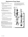
NOTE: Packing Repair Kit 820–968 is available. Reference numbers of parts included in the kit are marked
with an asterisk, i.e., (121*). For the best results, use
all the new parts in the kit, even if the old ones still look
good.
2. Align the hole in the rod (107) with the connecting
rod assembly (15). Use a screwdriver to push the
retaining spring (18) up and push in the pin (17).
Push the retaining spring (18) into place around
the connecting rod.
3. Replace the o-ring (27) if it is worn or damaged.
Reconnect the suction and drain hoses (32,33).
Install the front cover (13).
4. Tighten the packing nut (102) just enough to stop
leakage, but no tighter. Fill the packing nut/wet-cup
1/3 full with Graco TSL. Push the plug (123) into
the wet-cup.
NOTE: To minimize down time, and for the best sprayer
performance, check the motor brushes (see page 19)
and clean the transducer (see page 30) whenever you repack the pump. Replace these parts as needed.
Removing the pump (See Fig. 16.)
1. Flush the pump, if possible. Relieve pressure. Stop
the pump with the piston rod (107) in its lowest
position, if possible. To lower the piston rod manually, rotate the motor fan blades.
13
17
18
2. Remove the filter (85).
107
3. Remove suction hose or tube (32).(For suction
hose, refer to page 31.
120
*122
20
1
21
NOTE: If repairing only the intake valve assembly, go
to Intake valve repair, page 22.
*121
36
4. Use a screwdriver to push the retaining spring (18)
up and push out the pin (17).
33
32
5. Loosen the screws (21). Remove the pump (20).
27
Installing the pump (See Fig. 16 and 17.)
1. Mount the pump on the drive housing. Tap it into
the alignment pins with a soft hammer. Tighten the
screws (21) to 50 ft-lb (68 N.m).
38
Fig. 16
2
1
Torque to
50 ft–lb (68 N.m)
2
Apply sealant (42d)
Model 820–169 Shown
05174
17
WARNING
15
MOVING PARTS HAZARD
Be sure the retaining spring (18) is firmly
in the groove all the way around, to prevent the pin (17) from working loose due
to vibration. See Fig. 17.
If the pin works loose, it or other parts could break
off due to the force of the pump action. These parts
could be projected into the air and result in serious
injury or property damage, including the pump connecting rod or drive housing.
*119
118
123
18
1
Torque to
50 ft–lb (68 N.m)
21
1
102
Fig. 17
04655
Displacement Pump Repair
Intake valve repair (See Fig. 16)
1. Remove the suction hose. See Step 3, Removing
the pump.
2. Unscrew the intake valve (118). Remove the
o-ring (119*), ball guide (120), stop pin (122*) and
ball (121*) from the valve.
3. Clean and inspect the parts for wear or damage.
Replace parts as needed. Use a new o–ring
(119*). If no further service is needed, reassemble
the pump.
2. Stack these parts onto the piston valve (108) one
at a time: the backup washer (126*) and u-cup
(125*), the female gland (114*), alternately three
plastic (112*) with two leather packings (113*), and
the male gland (111*). See Fig. 18.
1
Throat packings
2
Piston packings
3
Intake valve
123
Disassembling the pump (See Fig. 18.)
102
1. Remove the intake valve (118).
2. Loosen the packing nut (102) and plug (123).
3. Use a plastic mallet to tap the piston rod (107)
down, and then pull the rod out through the bottom
of the cylinder.
107
1
*103
105*
Lips down
6. Clamp the flats of the piston rod in a smooth jaw
vise. Use an open-end wrench to loosen the nut
(110) and then unscrew the piston valve (108).
110
106*
111
4. Remove the packing nut (102) and throat packings.
5. Loosen the jam nut (117). Remove the cylinder
(115) and the o-ring (116*).
109*
*104
*113
112*
Lips up
101
114*
125*
Lips down
126*
117
108
7. Remove all parts from the piston valve (108).
Reassembling the pump
NOTE: Alternate plastic and leather packings. See Fig.
18. The lips of the throat V-packings face down. The
lips of the piston V-packings face up. Incorrect installation damages the packings and causes pump leakage.
*116
120
121
122*
115
NOTE: Soak the leather packings in oil before reassembling the pump.
1. Check the outside of the piston rod (107) and the
inside of the cylinder (115) for wear. Replace worn
parts to ensure a good seal with the new packings.
2
3
119
118
Fig. 18
03148A
Displacement Pump Repair
3. Tighten the nut (110) onto the piston valve (108) to
2 in-lb (0.23 N.m). See Fig. 19.
1
Torque to
2 in–lb (0.23 N.m)
107
2
Apply one drop of
sealant to these
threads
109*
6. Hand tighten the valve into the piston rod just until
the nut (110) contacts the rod. See Fig. 20.
7. Place the flats of the rod (107) in a smooth jaw
vise.
110
8. CAREFULLY tighten the nut (110) against the piston rod to 19 ft-lb (25 N.m). See Fig. 20.
*111
Use two wrenches to maintain the alignment mentioned in NOTE below Step 3.
*113
112*
*125
114*
*126
1
2
108
Fig. 19
1720
NOTE: Note the alignment of the piston (108) to the
nut (110). Maintain this alignment through Step 8.
Torque nut against rod
to 19 ft–lb (25 N.m)
Do not allow nut (110)
to move relative to
piston (108) when
tightening piston
against rod.
110
4. Clean all residue from the piston valve threads.
Apply one drop of adhesive, supplied, to the
threads.
5. Place the ball (109*) on the piston valve (108). See
Fig. 19.
CAUTION
Step 6, tightening the piston valve into the rod, is
critical. Follow the procedure carefully to avoid
damaging the packings by overtightening.
1
107
2
108
Fig. 20
1721
9. Stack these parts one at a time into the top of the
manifold (101): the male gland (106*), alternately
three plastic packings (104*) with two leather packings (105*), and then the female gland (103*). See
Fig. 22.
10. Install the packing nut (102) and plug (123), but
leave loose for now. See Fig. 22.
Displacement Pump Repair
11. Place a new o-ring (116*) firmly in the cylinder
groove. See Fig. 21.
15. Torque the cylinder jam nut (117) to 73 ft-lb
(98 N.m). See Fig. 21.
12. Coat the piston rod and packings with oil. Carefully
slide the assembly into the top of the cylinder
(115). See Fig. 21.
16. Install the pump. See page 21.
13. Put the manifold upside down in a vise. Fully
thread the jam nut (117) onto the cylinder (115).
Guide the rod/cylinder assembly down through the
manifold (101). Screw the cylinder (115) into the
manifold. See Fig. 21.
1
Leather packings
2
Poly packings
3
Lips of V–packings
must face down
4
Lips of V–packings
must face up
5
Torque to 53 ft–lb
(71 N.m)
107
123
102
101
102
*103
1
Torque jam nut (117)
to 73 ft–lb (98 N.m)
2
Torque cylinder (115)
into manifold (101) to
53 ft–lb (71 N.m)
3
Torque intake valve (116)
into cylinder (115) to
53 ft–lb (71 N.m)
4
104*
2
*105
1
3
106*
*116
107
3
101
Piston assembly
117
110
*111
116*
4
117
1
115
2
118
Fig. 21
*113
1
4
114*
108
125*
115
126*
122*
3
120
05118
14. Place the ball guide (120), stop pin (122) and ball
(121*) in the cylinder (115). Screw the intake valve
into the cylinder and torque to 53 ft-lb
(71 N.m). This will also properly torque the cylinder
into the manifold. See Fig. 22.
4
112*
2
*119
5
121*
118
Fig. 22
03147
Motor
9. Align the new motor with the base and reinstall the
screws (46).
WARNING
INJECTION HAZARD
To reduce the risk of serious injury,
whenever you are instructed to relieve
pressure, follow the Pressure Relief
Procedure on page 9.
10. Assemble the drive housing to the motor. Follow
steps 8 to 10 on page 27.
11. Connect the wires in the junction box. Refer to Fig.
26 on page 26. Install the junction box.
12. Connect the piston rod (107) to the drive housing;
see page 21, Installing the Pump, Step 2 and the
WARNING following it.
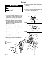
NOTE: See Fig. 25 except where noted.
1. Relieve pressure.
17
2. Try to stop the pump with the piston rod (107) in its
lowest position. To lower the piston rod manually,
rotate the motor fan blades. Use a screwdriver to
push the retaining spring (18) up and push out the
pin (17). See Fig. 23.
3. Remove the screws (56) and lower the junction
box (59). Disconnect the motor wires and the pressure control wire (A) from the motor start board.
Refer to Fig. 26 on page 26.
15
18
Fig. 23
01068
4. Remove the front cover (13).
107
5. Turn the displacement pump rod (107) so the pin
hole aligns with the bottom drive housing screw
(19). See Fig. 24. Remove the three drive housing
screws and lockwashers (19,6). Also see Fig. 25.
6. Remove the two motor screws (5) and the lock
washers (6).
19,6
7. Tap the lower rear of the drive housing (11) with a
plastic mallet to loosen the motor. Pull the drive
housing straight off the motor while guiding the
harness (A) from the motor. Do not allow the gear
(16) to fall. Read the CAUTION on page 27.
8. Remove the two screws (46) and lift the motor off
the base (66).
01074
Fig. 24
1
C
A
12
5
4
6
B
16
11
1
Torque to 80 in–lb (9 N.m)
2
Quantity of three
3
Quantity of one
6
1
19
59
13
3
31
46
56
34
2
02839A
Fig. 25
Motor Start Board
WARNING
INJECTION HAZARD
To reduce the risk of serious injury,
whenever you are instructed to relieve
pressure, follow the Pressure Relief
Procedure on page 9.
5. Install the new cord (50) in the reverse order of
disassembly.
6. Install the junction box. Be sure no leads are
pinched against the motor or by the motor start
board. Also be sure the gasket (89) is installed.
On/Off Switch
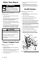
NOTE: See Fig. 26 for this procedure.
NOTE: See Fig. 26 for this procedure.
1. Relieve pressure.
1. Relieve pressure.
2. Remove the junction box screws (56) and lower
the junction box (59).
2. Remove the junction box screws (56) and lower
the junction box (59).
3. Remove the nut and rubber boot (55).
3. Disconnect the motor wires (B) and the 3-wire connector (A) from the motor start board (47). Observe where connections are made.
4. Remove the screws (58) and motor start board
(47). Transfer the white thermal paste from the old
board to the new board.
5. Install the new motor start board. Reconnect all
wires. Install the junction box. Be sure no leads are
pinched against the motor or by the motor start
board. Also be sure the gasket (89) is installed.
CAUTION
Be sure the flat blade of the insulated male connector is centered in the wrap–around blade of the
female connector when the connections are made.
4. Disconnect the black wires from the ON/OFF
switch (52) and remove the switch.
5. Place the ring terminal of the ground wire (53) over
the barrel of the new switch. Install the switch so
the internal tab of the anti-rotation ring (54) engages with the vertical groove in the threads of the
switch, and the external tab engages with the blind
hole (C) of the junction box.
6. Powder the inside of the rubber boot (55) with talcum, then shake the excess out of the boot. Install
the nut and rubber boot and tighten.
7. Reconnect the ON/OFF switch black wires.
8. Install the junction box. Be sure no leads are
pinched against the motor or by the motor start
board. Also be sure the gasket (89) is installed.
MOTOR
Route all wires carefully to avoid interference with
the motor start board or junction box.
GREEN
These precautions are essential to reduce the risk
of a malfunction.
49
BLACK/
WHITE
Power Supply Cord
GREEN/
53 YELLOW
50
51
89
52
BLACK
54
B
NOTE: See Fig. 26 for this procedure.
59
1. Relieve pressure.
2. Remove the junction box screws (56) and lower
the junction box (59).
RED
58
C
A
3. Disconnect the power supply cord leads, including
the green wire to the grounding screw (49).
4. Loosen the strain relief bushing (51). Remove the
power supply cord (50).
55
56
47
Fig. 26
04720
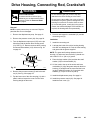
Drive Housing, Connecting Rod, Crankshaft
WARNING
CAUTION
INJECTION HAZARD
To reduce the risk of serious injury,
whenever you are instructed to relieve
pressure, follow the Pressure Relief
Procedure on page 9.
Removal
Do not allow the gear (16) to fall; it may stay
attached to the drive housing or to the motor.
Do not lose the thrust balls (11a or 4a) or let them
fall between the gears, which will damage the drive
housing if not removed. The balls, which are heavily covered with grease, usually stay in the gear recesses, but could be dislodged. If the balls are not
in place, the bearings will wear prematurely.
NOTE: Inspect parts as they are removed. Replace
parts that are worn or damaged.
1. Remove the displacement pump. See page 21.
6. Remove and inspect the crankshaft (12) and the
connecting rod (15).
2. Remove the pressure control (64). See page 29.
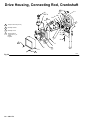
Installation
3. Turn the displacement pump rod (107) so the pin
hole aligns with the bottom drive housing screw
(19). See Fig. 27. Remove the three drive housing
screws and lockwashers (19,6). Also see Fig. 28
on page 28.
8. Lubricate the inside of the drive housing bearing
with SAE non-detergent oil. Pack the roller bearing
and gears with the grease supplied.
NOTE: The gears and bearings between the drive
housing (11) and motor front end bell (C) should contain a total of 3 fl. oz. (29 cc) of grease.
107
9. Place the large washer (12a) and then the small
washer (12b) on the crankshaft (12).
19,6
Fig. 27
7. Install the connecting rod.
01074
4. Remove the two motor screws (5) and lock washers (6). See Fig. 28 on page 28.
10. Lift the crank to the top of the stroke and insert
crankshaft (12). Align the gears and push the drive
housing (11) straight onto the motor and the locating pins. Install the screws (19, 5) and their lockwashers (6). Torque to 80 in–lb (9 N.m).
11. Install the displacement pump. See page 21.
5. Tap the lower rear of the drive housing (11) with a
plastic mallet to loosen the motor. Pull the drive
housing straight off the motor.
12. Install the pressure control (64). See page 29.
Install the front cover (13).
Drive Housing, Connecting Rod, Crankshaft
1
64
REF A
4
12a
1
Torque to 80 in–lb (9 N.m)
2
Quantity of three
3
Quantity of one
4
Apply a total of
3 fl. oz.(29 cc) of
grease
to gears.
12
11a
16
5,6
C
4a
12b
A
47
59
56
3
31
11
6
15
13
34
Fig. 28
19
1
2
02840
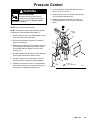
Pressure Control
WARNING
INJECTION HAZARD
To reduce the risk of serious injury,
whenever you are instructed to relieve
pressure, follow the Pressure Relief
Procedure on page 9.
7. Loosely install the screws (63) and then torque
them to 21 in–lb (2.4 N.m).
8. Install the front cover (13). Connect the harness
(A) to the motor start board (47).
9. Install the junction box. Be sure no leads are
pinched against the motor or by the motor start
board.
NOTE: See Fig. 29 for this procedure.
64
NOTE: The pressure control (64) cannot be repaired
or adjusted. If it has malfunctioned, replace it.
63
1. Remove the front cover (13). Remove the screws
(56). Lower the junction box (59).
1
11
13
2. Disconnect the harness connector (A) from the
motor start board (47).
3. Remove the screws (63). Pull forward on the pressure adjusting knob and tip the pressure control
(64) forward and up to detach it from the drive
housing (11).
A
4. Guide the harness (A) through the motor and drive
housing and remove the pressure control.
5. Guide the harness of the new pressure control
through the drive housing and motor passages.
6. Install the new pressure control. Tip the pressure
control down and back into the drive housing (11).
Do not pinch or damage the harness (A).
59
56
1
Torque to
21 in–lb (2.4 N.m)
05175
Fig. 29
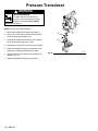
Pressure Transducer
WARNING
INJECTION HAZARD
To reduce the risk of serious injury,
whenever you are instructed to relieve
pressure, follow the Pressure Relief
Procedure on page 9.
NOTE: See Fig. 30 for this procedure.
1. Remove the displacement pump. See page 21.
29
2. Use a pull–twist motion to remove the transducer
(29) from the pump manifold (101).
3. Clean paint residue from the hole in the manifold;
do not scratch the surface of the hole.
101
4. Lightly apply oil to the o-ring of the new transducer.
5. Install the transducer in the pump manifold, while
guiding the o-ring and backup ring into place.
6. Align the holes in the transducer as shown by the
arrows in Fig. 30.
7. Install the displacement pump. See page 21.
Fig. 30
02841A
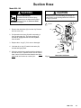
Suction Hose
Model 820–169
WARNING
INJECTION HAZARD
To reduce the risk of serious injury,
whenever you are instructed to relieve
pressure, follow the Pressure Relief
Procedure on page 9.
CAUTION
Misalignment or cross-threading will damage the
parts and/or create shavings which can cause the
o–ring (27) to leak.
1
Lubricate
1. Remove the drain hose (33) from the clip. Remove
the front cover (13).
13
2. Pull upward on the hose (32) while unscrewing it
from the inlet tube (38). The hose coupling (A)
threads will engage and the hose will separate
from the tube.
33
36
3. Replace the o–ring (27) if it is worn or damaged.
4. Lubricate the o–ring (27) and the inlet tube (38)
threads with light grease.
5. Align the suction hose coupling with the threads of
the inlet tube (38). Tighten the hose onto the tube at
least 4 turns to ensure that the threads have disengaged and can function as a swivel joint.
1
32
27
A
38
Fig. 31
Model 820–169 Shown
05176
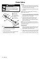
Drain Valve
Repair
WARNING
INJECTION HAZARD
To reduce the risk of serious injury,
whenever you are instructed to relieve
pressure, follow the Pressure Relief
Procedure on page 9.
1
42a
42b
1
42d
2
Apply grease
to face of base
3
Torque into pump
manifold to 185 in–lb
(21 N.m)
4
Handle shown
in closed position
42c
3
Apply thread sealant
2
42
44
NOTE: Whenever the gasket (42a) is removed, replace it with a new one.
3. Coat the o-ring (42d) with grease. Press the stem
into the valve body. Install the spring, washers and
spring retainer into the valve body.
4. Place the seat (42b) in the valve body so the
lapped side is toward the ball. Apply a small
amount of grease to the new gasket (42a) and install it in the valve body.
Replacement
4
45
02819
1. Turn the handle (45) to the closed position. Drive
out the pin (44). Remove the handle.
2. Remove the base (43).
3. Unscrew the drain valve (42). The gasket (42a)
and seat (42b) will stay in the valve.
2. If replacing the gasket (42a) or seat (42b), pry out
the gasket.
NOTE: The gasket will protrude from the end of the
valve until the valve is tightened into pump, which correctly seats the gasket.
43
Fig. 32
1. Unscrew the spring retainer from the valve body.
Remove the spring, washers and stem/ball. Clean
any debris from the ball or seat area.
1. Apply a small amount of thread sealant (42e) onto
the valve (42) threads. Tighten the valve into the
pump manifold to 185 in–lb (21 N.m).
2. Lightly grease the face of the base (43) and install
the base. Turn the stem so the pin hole is vertical.
3. Securely install the handle (45) and drive pin (44).
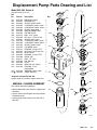
Displacement Pump Parts Drawing and List
Model 820–963, Series A
123
Includes items 101 to 127
Ref
No.
Part No.
Description
101
102
103*
104*
105*
106*
107
108
109*
110
111*
112*
113*
114*
115
116*
117
118
119*
120
121*
122*
123
124*
125*
820–970
820–287
820–286
820–285
820–284
820–283
820–980
820–484
820–276
820–282
820–281
820–292
820–280
820–463
820–979
820–617
820–972
820–975
820–969
820–289
820–277
820–288
820–485
820–462
820–278
MANIFOLD, pump
1
PACKING NUT
1
GLAND, female, throat
1
V–PACKING, plastic, throat 3
V–PACKING, leather, throat 2
GLAND, male, throat
1
DISPLACEMENT ROD
1
PISTON VALVE
1 *105
BALL, 5/16”, piston
1
NUT, hex, 1/2–20 unf–2b
1
GLAND, male, piston
1
V–PACKING, plastic, piston 3
V–PACKING, leather, piston 2
GLAND, female, piston
1
101
CYLINDER, pump
1
PACKING, o–ring, PTFE 1
NUT, jam,1-3/8 18 unef–2b
1
INLET VALVE
1
PACKING, o–ring, PTFE 1
GUIDE, ball
1
BALL, 1/2”, inlet
1
PIN, ball stop
1
PLUG
1 127
SEALANT (not shown)
1
PACKING, u–cup,
1
polyurethane
WASHER, backup, steel
1
117
LABEL, Warning
1
126* 820–464
127 188–663
Qty
102
103*
107
109*
104*
110
111*
106*
*113
112*
114*
125*
126*
*Supplied in Repair Kit 820–967.
Keep a repair kit on hand to reduce down time.
*116
108
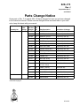
MANUAL CHANGE SUMMARY
This manual has been updated to:
add the Model 820–248, Series A, Upright Cart
assembly.
115
120
*122
correct errors to the Displacement Pump Parts
Drawing and List.
121*
correct pump model number from 820–877 to
820–963.
119*
118
03148A
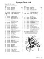
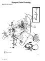
Sprayer Parts Drawing
Model 820–169, Series A
30
39
74
1
2
REF 33
3
Label
See detail
on page 35
Torque to 75–85
in-lb
67
3
4e
1
5
24
64
3
6
4
65
REF 32
4a
16
12b
4f
12
63
19
6
11b
4g
12a
1
1
89
15
11a
17
13
11
26
18
35
2
50
66
OUTSIDE
LABEL
56
14
29
INSIDE
LABEL
42a
42b
28
31
34
21
20
42d
42c
23
46
42
36
43
32
27
33
45
44
37
38
25
O2833A
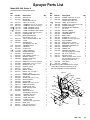
Sprayer Parts List
Model 820–169, Series A
Includes items 3 to 89 as listed below
Ref.
No. Part No.
3
4{
820–879
821–063
4a.a
4b.b
4c.c
4d.dY
4e.eY
4f.fY
5
6
11
820–457
820–881
820–439
187–784
187–791
187–975
820–500
820–273
820–246
11a
11b
12
820–457
820–883
820–884
12a
12b
13
14Y
15
16
17
18
19
820–602
820–603
821–064
177–762
820–604
820–605
820–306
820–304
820–886
20
21
23
24
25
26
27
28
820–963
820–888
820–889
820–890
821–052
820–892
820–893
820–421
29
30
31
32
33
34
35
36
37
38
39
42
820–894
820–895
820–896
820–897
820–898
820–899
820–172
820–900
820–901
820–902
820–903
820–904
42a
42b
42c
42d
42e
820–905
820–906
820–907
820–823
820–909
Description
GRIP, handle
MOTOR KIT
Includes items 4a to 4f
. BALL, sst, 1/4” dia.
. TERMINAL, flat, 1/4” (f), 18 awg
. TERMINAL, 3/16” (m), 16 awg
. LABEL, DANGER, French
. LABEL, DANGER, English
. LABEL, WARNING, electric shock
SCREW, socket head, 1/4–20 x 1”
LOCKWASHER, 1/4”
DRIVE HOUSING KIT
Includes item 11a, 11b
. BALL, stainless steel, 1/4” dia.
. PLUG
CRANKSHAFT
Includes items 12a, 12b
. BEARING, thrust
. BEARING
COVER, front
LABEL, WARNING
CONNECTING ROD
GEAR REDUCER
PIN, headless, 3/8” dia. x 1”
SPRING, retaining
SCREW, socket head,
1/4–20 x 1–1/4”
PUMP KIT see parts on page 29
CAPSCREW, 7/16–14 x 1–3/4”
SCREW, 5/16–18 x 1–1/4”
HANDLE, sprayer
CAP, tubing
LEG, with gusset
O–RING
NIPPLE, hex, 1/4 npsm x
1/4 npt, 1–3/16”
PRESSURE TRANSDUCER
CLIP, 3/4”
SCREW, filh, 8–32 x 1–1/4”
SUCTION HOSE & TUBE
DRAIN HOSE
SCREW, filh, 8–32 x 2–1/2”
LABEL, identification
ADAPTER, tube, 9/16–18
LEG, sprayer
INLET TUBE
STRAINER
DRAIN VALVE KIT
Includes items 42a to 42e
. GASKET, valve seat
. SEAT, drain valve
. STEM, drain valve
. O–RING, stem
. SEALANT, pipe (not shown)
Qty.
1
1
1
2
2
1
1
1
2
5
1
1
1
1
1
1
1
1
1
1
1
1
5
1
2
4
1
4
1
1
2
1
1
1
1
1
3
1
1
2
1
1
1
1
1
1
1
1
Ref.
No. Part No.
43
44
45
46
47
Description
Qty.
820–910
820–911
820–912
820–913
820–965
BASE, valve
PIN, grooved, 3/32 x 1”
HANDLE, drain valve
SCREW, washer/hex hd, 5/16”
MOTOR START BOARD
includes items 47a to 47c
48Y
186–620
LABEL, ground terminal
49
820–560
SCREW, mach, pnhd, 10–24 x 5/8”
50
820–916
POWER CORD SET
51
820–917
STRAIN RELIEF BUSHING,
3/8–18 npt
52
820–342
SWITCH, ON/OFF
53
820–918
GROUND HARNESS
54
820–919
LOCKING RING
55
820–341
BOOT, switch
56
820–920
SCREW, filh, 10–24 x 3”
58
820–424
SCREW, pan hd, 8–32 x 5/16”
59
820–921
JUNCTION BOX
63
820–922
SCREW, filh, 10–24 x 1–5/8”
64
820–923
PRESSURE CONTROL KIT
65
820–927
SCREW, button head, 5/16”
BASE, motor
66
820–924
67
820–925
CONTRACTOR GUN
See manual 308–614 for parts
68
820–619
TSL, 8 oz. (not shown)
HOSE, grounded, nylon; 1/4” ID;
74
820–516
cpld 1/4 npsm(f); 50 ft (15 m);’
spring guards both ends
89
820–924
GASKET
Y Extra warning labels available free of charge.
{ Motor Brush and Spring Replacement Kit,
821–022 is available. Purchase separately.
1
1
1
2
1
1
1
1
1
1
1
1
1
4
2
1
2
1
2
1
1
1
1
1
MOTOR
GREEN
48
49
GREEN/
53 YELLOW
50
51
4c
BLACK/
WHITE
52
BLACK
54
4b
55
59
RED
58
4c
47
04720
Sprayer Parts Drawing
Model 820–248, Series A
3
24
23
62
4
4a
64
6
5
4e
72
1
12b
16
12
63
12a
11b
4f
4g
6
15 19
11a
17
13
89
11
2
59
56
14
26
50
INSIDE
LABEL
29
28
20
21
42a
42b
42d
42c
35
OUTSIDE
LABEL
34
1
46
18
31
1
66
42
65
36
65
88
32
33
30
39
37
43
44
45
25
74
67
1
Label
2
See page 37 for detail
O5121
Sprayer Parts List
Model 820–248, Series A
Includes items 3 to 89 as listed below
Ref.
No. Part No.
3
4{
821–038
821–063
4a.a
4b.b
4c.c
4d.dY
4e.eY
4f.fY
5
6
11
820–457
820–881
820–439
187–784
187–791
187–975
820–500
820–273
821–069
11a
11b
12
820–457
820–883
820–884
12a
12b
13
14Y
15
16
17
18
19
820–602
820–603
821–064
177–762
820–604
820–605
820–306
820–304
820–886
20
21
23
24
25
26
28
820–963
820–888
821–037
820–468
820–474
821–066
820–421
29
30
31
32
33
34
35
36
37
39
42
820–894
820–403
820–896
821–067
820–862
820–899
820–172
820–579
820–469
821–026
820–904
42a
42b
42c
42d
42e
43
44
45
820–905
820–906
820–907
820–823
820–909
820–910
820–911
820–912
Description
SLEEVE, cart
MOTOR KIT
Includes items 4a to 4f
. BALL, sst, 1/4” dia.
. TERMINAL, flat, 1/4” (f), 18 awg
. TERMINAL, 3/16” (m), 16 awg
. LABEL, DANGER, French
. LABEL, DANGER, English
. LABEL, WARNING, electric shock
SCREW, socket head, 1/4–20 x 1”
LOCKWASHER, 1/4”
DRIVE HOUSING KIT
Includes item 11a, 11b
. BALL, stainless steel, 1/4” dia.
. PLUG
CRANKSHAFT
Includes items 12a, 12b
. BEARING, thrust
. BEARING
COVER, front
LABEL, WARNING
CONNECTING ROD
GEAR REDUCER
PIN, headless, 3/8” dia. x 1”
SPRING, retaining
SCREW, socket head,
1/4–20 x 1–1/4”
PUMP KIT see parts on page 29
CAPSCREW, 7/16–14 x 1–3/4”
SCREW, 6–32 x .187
HANDLE, sprayer
PLUG, tubing
WHEEL, sprayer
NIPPLE, hex, 1/4 npsm x
1/4 npt, 1–3/16”
PRESSURE TRANSDUCER
CLIP, spring
SCREW, filh, 8–32 x 1–1/4”
SUCTION TUBE
DRAIN TUBE
SCREW, filh, 8–32 x 2–1/2”
LABEL, identification
CONNECTOR, tube
RING, retaining, wheel
STRAINER
DRAIN VALVE KIT
Includes items 42a to 42e
. GASKET, valve seat
. SEAT, drain valve
. STEM, drain valve
. O–RING, stem
. SEALANT, pipe (not shown)
BASE, valve
PIN, grooved, 3/32 x 1”
HANDLE, drain valve
Qty.
2
1
1
2
2
1
1
1
2
3
1
1
1
1
1
1
1
1
1
1
1
1
5
1
2
4
1
2
2
2
1
1
1
1
1
3
1
1
2
1
1
1
1
1
1
1
1
1
1
Ref.
No. Part No.
Description
Qty.
SCREW, washer/hex hd, 5/16”
MOTOR START BOARD
includes items 47a to 47c
48Y
186–620
LABEL, ground terminal
49
820–560
SCREW, mach, pnhd, 10–24 x 5/8”
50
820–916
POWER CORD SET
51
820–917
STRAIN RELIEF BUSHING,
3/8–18 npt
52
820–342
SWITCH, ON/OFF
53
820–918
GROUND HARNESS
54
820–919
LOCKING RING
55
820–341
BOOT, switch
56
820–920
SCREW, filh, 10–24 x 3”
58
820–424
SCREW, pan hd, 8–32 x 5/16”
59
820–921
JUNCTION BOX
RING, retaining, handle
62
820–475
63
820–922
SCREW, filh, 10–24 x 1–5/8”
64
820–923
PRESSURE CONTROL KIT
65
820–294
WASHER, axle
66
821–068
FRAME, cart
67
820–925
CONTRACTOR GUN
See manual 308–614 for parts
68
820–619
TSL, 8 oz. (not shown)
72
820–477
BUTTON, spring
HOSE, grounded, nylon; 1/4” ID;
74
820–516
cpld 1/4 npsm(f); 50 ft (15 m);’
spring guards both ends
88
820–488
CLIP, spring
89
820–924
GASKET
Y Extra warning labels available free of charge.
{ Motor Brush and Spring Replacement Kit,
821–022 is available. Purchase separately.
46
47
2
1
820–913
820–965
1
1
1
1
1
1
1
1
4
2
1
2
2
1
2
1
1
1
2
1
1
1
MOTOR
GREEN
48
49
GREEN/
53 YELLOW
50
51
4c
BLACK/
WHITE
52
BLACK
54
4b
55
59
RED
58
4c
47
04720
Notes
Notes
Technical Data
DANGER LABELS
Power Requirements . . . . . . . . . . . . . . . . . . . . 120 VAC,60Hz,
1 phase, 15 amp minimum
Generator . . . . . . . . . . . . . . . . . . . . . . . . . . 3000 Watt minimum
Working Pressure Range . . . . . . . . . 0–2750 psi (0 – 195 bar)
Motor . . . . . . . . . . . . . . . . . . . . . . . . . . . . . . . . . . . . . . . . . . 3/4 hp
Cycles/Gallon (liter) . . . . . . . . . . . . . . . . . . . . . . . . . . . 620 (164)
Delivery . . . . . . . . . . . . . . . . . . . . . . . . . . . . . 0.50 gpm (1.9 lpm)
Tip Size . . . . . . . . . . . . . . . . . . . . . . . . one gun to new 0.023 tip
with latex at 2000 psi (138 bar)
Power Cord . . . . . . . . . . . . . . . No. 14 AWG, 3 wire, 6’ (1.8 m)
Inlet Paint Strainer . . . . . . . . . . . . . . . . 12 mesh (1525 micron)
Stainless Steel Screen, reusable
Pump Inlet Size . . . . . . . . . . . . . . . . . . . . . . . . . . . . . . 1/2 npt(f)
Fluid Outlet Size . . . . . . . . . . . . . . . . . . . . . . . . . . . . . 1/4 npsm
Wetted Parts:
Displacement Pump . . . . . . . Stainless steel, Carbon steel,
PTFE,Aluminum, Polyethylene, Delrin, Leather
The English language DANGER label shown on
page 1 is also on your sprayer. If you have painters who do not read English, order one of the following labels to apply to your sprayer. The drawing below shows the best placement of these labels for good visibility.
Order the labels directly from Graco, free of
charge: 1–800–328–0211
French
Spanish
German
Greek
Korean
English
185–956
185–961
186–041
186–045
186–049
185–953
Apply other
language here
05178
NOTE: is
Delrin
Delrin
a registered trademark of the DuPont Company.
Dimensions
Model 820–169
Model 820–248
Weight (dry w/o packaging)
37 lb (17 kg)
47 lb (21.4 kg)
Height
19 in. (483 mm)
29.5 in. (749 mm) Handle down
39.5 in. (1003 mm) Handle up
Length
15 in. (381 mm)
21 in. (533 mm)
Width
14 in. (356 mm)
20.5 in. (521 mm)
The Graco Warranty and Disclaimers
WARRANTY
Graco warrants all equipment manufactured by it and bearing its name to be free from defects in material and workmanship on the date of sale by
an authorized Graco distributor to the original purchaser for use. As purchaser’s sole remedy for breach of this warranty, Graco will, for a period of
twelve months from the date of sale, repair or replace any part of the equipment proven defective, with the exception of defects in parts on the drive
train/gear box on EM and GM sprayers or power train on EH and GH sprayers, which will be repaired or replaced for twenty-four months from the
date of sale for Gas–Hydraulic (GH) and Gas-Mechanical (GM) sprayers and for thirty-six months from the date of sale for Electric-Mechanical
(EM), Electric-Hydraulic (EH), 390st and 490st sprayers. This warranty applies only when the equipment is installed, operated and maintained in
accordance with Graco’s written recommendations.
This warranty does not cover, and Graco shall not be liable for, any malfunction, damage or wear caused by faulty installation, misapplication, abrasion, corrosion, inadequate or improper maintenance, negligence, accident, tampering, or substitution of non–Graco component parts. Nor shall
Graco be liable for malfunction, damage or wear caused by the incompatibility with Graco equipment of structures, accessories, equipment or materials not supplied by Graco, or the improper design, manufacture, installation, operation or maintenance of structures, accessories, equipment or
materials not supplied by Graco.
This warranty is conditioned upon the prepaid return of the equipment claimed to be defective to an authorized Graco distributor for verification of
the claim. If the claimed defect is verified, Graco will repair or replace free of charge any defective parts. The equipment will be returned to the original purchaser transportation prepaid. If inspection of the equipment does not disclose any defect in material or workmanship, repairs will be made at
a reasonable charge, which charges may include the costs of parts, labor and transportation.
DISCLAIMERS AND LIMITATIONS
The terms of this warranty constitute purchaser’s sole and exclusive remedy and are in lieu of any other warranties (express or implied), including
warranty of merchantability or warranty of fitness for a particular purpose, and of any non–contractual liabilities, including product liabilities,
based on negligence or strict liability. Every form of liability for direct, special or consequential damages or loss is expressly excluded and denied. In
no case shall Graco’s liability exceed the amount of the purchase price. Any action for breach of warranty must be brought within two (2) years of
the date of sale.
EQUIPMENT NOT COVERED BY GRACO WARRANTY
Graco makes no warranty, and disclaims all implied warranties of merchantability and fitness for a particular purpose, with respect to accessories, equipment, materials, or components sold but not manufactured by Graco. These items sold, but not manufactured by Graco (such as electric
motor, switches, hose, etc.) are subject to the warranty, if any, of their manufacturer. Graco will provide purchaser with reasonable assistance in
making any claim for breach of these warranties.
Sales Offices: Atlanta, Chicago, Detroit, Los Angeles
Foreign Offices: Belgium; Canada; England; Korea; Switzerland; France; Germany; Hong Kong; Japan
GRACO INC.
P.O. BOX 1441 MINNEAPOLIS, MN
PRINTED IN U.S.A.
55440–1441
November, 1992; Revised June, 1995
82X–173
Rev. J
Supersedes Rev. F
and PCN H
Parts Change Notice
Some parts in Rev. F of manual 820–173 have changed but have not yet been changed
in the instruction manual. Please note the changes below and mark them in your manual or keep this sheet with your manual.
Assembly No.
820–248
820–169
Series
Letter
Change
Part That
Changed
Ref
No.
Part Description
Description of Change
C
821–038
3
SLEEVE, cart
Replaced by 820–955
821–037
23
SCREW, 10–32 x 1/4”
Replaced by 820–559
820–468
24
HANDLE, sprayer
Replaced by 820–567
820–474
25
PLUG, tubing
Replaced by 820–558
821–066
26
WHEEL, sprayer
Replaced by 820–333
820–403
30
CLIP, spring
Replaced by 820–344
821–067
32
SUCTION TUBE
Replaced by 821–030
820–916
50
POWER CORD SET
Replaced by 821–070
820–475
62
RING, retaining, handle
Replaced by 820–562
820–294
65
WASHER, axle
Deleted
821–068
66
FRAME, cart
Replaced by 821–073
820–477
72
BUTTON, spring
Replaced by 820–953
New
90
HANGER, pail
Added 821–031
New
91
SCREW, oval head,
10–24 x 3/8 (2)
Added 821–025
New
92
LABEL, warning
Added 290–061
New
93
HUBCAP (2)
Added 820–263
New
94
WASHER, handle (2)
Added 820–564
820–895
30
CLIP, 3/4 in.
Replaced by 821–076
820–898
33
DRAIN HOSE
Replaced by 821–077
C
continued on page 2.
29 Jul 96
Other Changes
Page 23: Change instruction in step 3.:
From:
Tighten the nut (110) onto the piston valve (108) to 2 in-lb (0.23 Nm).
To:
Tighten the nut (110) onto the piston valve (108) to 5 in-lb (0.57 Nm).
Change note 1 of Fig. 19:
From:
Torque to 2 in-lb (0.23 Nm)
To:
Torque to 5 in-lb (0.57 Nm)
Change second instruction in step 4.:
From:
Apply one drop of adhesive, supplied, to the threads.
To:
Apply one strip of adhesive, supplied, to the threads.
Change first instruction in step 8.:
From:
CAREFULLY tighten the nut (110) against the piston rod to 19 ft-lb (25 Nm).
To:
Carefully tighten the nut (110) against the piston rod to 30 ft-lb (40 Nm).
Change note 1 of Fig. 20:
From:
Torque nut against rod to 19 ft-lb (25 Nm)
To:
Torque nut against rod to 30 ft-lb (40 Nm)
Page 36: Added drawings of items 90 through 92.
91
92
90
Page 40: Change weight of Model 820–248 to 61 lb (27.7 kg).
29 Jul 96
82X–173 Rev J, Page 2