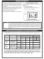
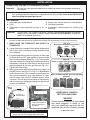
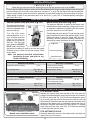
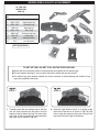
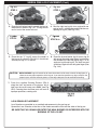
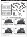
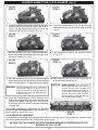
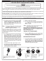
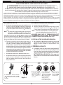
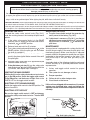
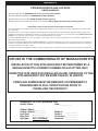
1
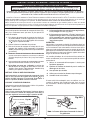
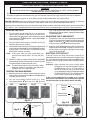
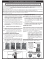
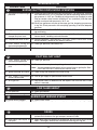
Owner’s
Manual
ROBERT H. PETERSON CO.
®
FPB55-24/30(P)
FPB55-24/30-11(M)(P)
FPB55-24/30-15(M)(P)
DESIGN CERTIFIED
to
Vented Decorative Appliance
ANSI Z21.60b-2004
FPB 55 SERIES VENTED GAS LOG SETS
FOR NATURAL OR PROPANE GAS
WARNING
If the information in this manual is not
followed exactly, a fire or explosion may
result, causing property damage, personal
injury, or loss of life.
Do not store or use gasoline or other
flammable vapors and liquids in the vicinity
of this or any other appliance.
WHAT TO DO IF YOU SMELL GAS
• Open a window.
• Do not try to light any appliance.
• Do not touch any electrical switch; do
not use any phone in your building.
• Immediately call your gas supplier from
a neighbor's phone and follow the gas
supplier's instructions.
• If you cannot reach your gas supplier,
call the fire department.
IMPORTANT:
This burner system is to be installed only in a solid-fuelburning fireplace with a working flue and constructed of
noncombustible material. Solid fuels shall not be burned
in a fireplace where this gas log set is installed. The
installation, including provisions for combustion, ventilation
air, and required minimum permanent vent opening,
must conform with the National Fuel Gas Code (ANSI
Z223.1/NFPA 54) and applicable local building codes. In
Canada, the installation must conform with the Natural
Gas and Propane Storage and Handling Installation Code
(CSA-B149.1). A damper clamp is included to maintain
the minimum permanent vent opening and to prevent
full closure of the damper blade. The chimney damper
should be fully opened when burning the log set. The
log set is designed to burn with yellow flames; thus,
adequate ventilation is absolutely necessary.
Installation and service must be
performed by an NFI Certified or
other qualified professional installer,
service agency, or the gas supplier.
Important:
READ THESE INSTRUCTIONS
CAREFULLY BEFORE STARTING
INSTALLATION OF THE LOG SET.
INSTALLER & CONSUMER:
These instructions MUST be retained
with this appliance.
For safe operation and proper performance of this product and to comply with certification,
listings, and building code acceptances, use ONLY Peterson Real-Fyre® controls, parts, and
accessories that have been specifically listed or certified for use with this burner system. Use
of other controls, parts, or accessories is prohibited and will void all warranties, certifications,
listings, and building code approvals, and may cause property damage, personal injury, and
loss of life.
ROBERT H. PETERSON CO. • 14724 East Proctor Avenue, City of Industry, CA 91746
REV 5 - 0801140855
1
L-A2-22408
manuel des
proprietaires
ROBERT H. PETERSON CO.
®
FPB55-24/30(P)
FPB55-24/30-11(M)(P)
FPB55-24/30-15(M)(P)
CONCEPTION CERTIFIÉE
à
Vented Decorative Appliance
ANSI Z21.60b-2004
SÉRIE FPB55 A EXHALÉ DES ENSEMBLES
DE NOTATION DE GAZ
AVERTISSEMENT:
Si les informations
dans ce manuel ne sont pas suivies exactement,
un feu ou explosion peut résulter cause
propriété endommage, blessure personnelle
ou perte de vie.
Ne mettez pas en réserve ou utilisez de
l'essence ou autre vapeurs inflammables et
liquides dans le voisinage de celui-ci ou tout
autre appareil.
CE QUI Faire Si VOUS avez SENTI le GAZ
• n'essaie pas d'allumer de l'appareil.
• ne touche pas de changement électrique;
ne utilisez pas du téléphone dans votre
bâtiment.
• appelle Immédiatement votre fournisseur
du gaz du téléphone d'un voisin et suit les
directives des fournisseur du gaz.
• Si vous ne pouvez pas atteindre votre
fournisseur du gaz, appelle le département
du feu.
Installation et service doivent être
exécutées par un [installer] qualifié agence
du service ou le fournisseur du gaz.
INSTALLATEUR & CONSOMMATEUR:
IMPORTANT:
LISEZ CES DIRECTIVES AVANT
AVEC SOIN de COMMENCER INSTALLATION
De VOTRE GROSSE BUCHE a MIS
Ce système de brûleur doit être installée seulement
dans une cheminée debrûlure avec une conduite
de cheminée fonctionnante et être construit avec
du matériel non-combustible. Combustibles solides
ne seront pas brûlaient dans une cheminée où un
gaz tronçonne l'ensemble est installé. Le minimum
permanent décharge l'ouverture a fourni par la cheminée
de la cheminée ou cheminée plus humide décharger
les produits du [flue] est inscrit sur. La cheminée plus
humide doit être arrangé maintenir dans une manière le
minimum permanent décharge l'ouverture. L’installation,
y compris des dispositions pour la combustion, air de
ventilation, et ouverture permanente minimum exigée de
passage, doit se conformer au code national de gaz de
carburant (norme ANSI Z223.1/NFPA 54) et aux codes
de bâtiment locaux applicables. Au Canada l'installation
doit conformer avec le courant PEUT/ CGA B149.1 et
B149.2 Installation Code. La Douche froide de cheminée
devrait être ouverte pleinement quand brûler l'ensemble
du journal. Votre ensemble du journal est conçu pour
brûler avec les flammes du jaune; donc la ventilation
adéquate est absolument nécessaire.
Ces directives doivent être retenues avec cet appareil
IMPORTANT: Pour se conformer à la certification, les listes et les acceptations de code de bâtiment, et
pour l’exploitation sûre et l’exécution appropriée de cet ensemble de notation, utilisent SEULEMENT de
Real-Fyre® pièces et accessoires de Peterson. L’utilisation d’autres commandes, pièces, ou accessoires
qui ne sont pas approuvés pour l’usage avec de Real-Fyre® ensembles de notation de gaz est interdite et
videra toutes les garanties, certifications, listes, et approbations de code de bâtiment, et peut causer des
dégats matériels, des blessures, ou la perte de la vie.
ROBERT H. PETERSON CO. • 14724 East Proctor Avenue, City of Industry, CA 91746
REV 5 - 0801140855
2
L-A2-22408
TABLE OF CONTENTS
TABLE OF CONTENTS
GENERAL INFORMATION
FIREPLACE SIZE REQUIREMENTS & BTU RATING INFORMATION
IMPORTANT INFORMATION
MINIMUM PERMANENT FREE VENT OPENING AREA AT CHIMNEY DAMPER
PRE-INSTALLATION AND FIREPLACE PREPARATION SAFETY
PARTS LIST FOR MANUAL SERIES VALVE
PARTS LIST FOR 11 SERIES VALVE
PARTS LIST FOR 15 SERIES VALVE
INSTALLATION
CONNECTING THE GAS TO THE BURNER SYSTEM
CHECKING GAS PRESSURE
INSTALLATION OF DECORATIVE COVER
SIERRA PINE LOG LIST & PLACEMENT
LAVA GRANULE PLACEMENT
CHARRED SUMMIT PINE LOG LIST & PLACEMENT
LAVA GRANULE PLACEMENT
LIGHTING INSTRUCTIONS - MANUAL PILOT VALVE
LIGHTING INSTRUCTIONS - SERIES 11 VALVE
LIGHTING INSTRUCTIONS - SERIES 15 VALVE
CHECKING PILOT FLAME APPEARANCE
DAMPER CLAMP INSTRUCTIONS
TROUBLESHOOTING
FLAME DESCRIPTION
AVAILABLE ACCESSORIES FOR THE GAS BURNER SYSTEM
WARRANTY
REV 5 - 0801140855
3
3
4
4
5
5
7
8
9
10
11
11
12
12
13
14
15
16
17
19
21
23
23
24
25
26
28
L-A2-22408
GENERAL INFORMATION
The Real-Fyre ® FPB55 Series gas log sets are
available with a variable flame height control valve that
can be used with an optional on/off remote transmitter
and receiver.
APPROVED INSTALLATIONS
Subject to minimum fireplace size requirements
specified below:
Solid-fuel-burning fireplaces;
A. Prefabricated fireplaces listed to UL-127
B. All other masonry fireplaces
A spark ignition system (piezo) allows the gas pilot to be
lit without the use of matches and permits the operation
of the appliance during a power outage.
This log set has been certified to:
VENTED DECORATIVE APPLIANCE-ANSI Z21.60b-2004
Fig. 4-1
Rear
width
HEIGHT
H
eight
DEPTH
Depth
F r ONT
ont
FR
w iWIDTH
d t h oOPENING
pening
Fireplace dimensions
Important:
For safe operation and proper performance of this product and to comply with certification,
listings, and building code acceptances, use ONLY Peterson Real-Fyre® controls, parts, and
accessories that have been specifically listed or certified for use with this burner system. Use
of other controls, parts, or accessories is prohibited and will void all warranties, certifications,
listings, and building code approvals, and may cause property damage, personal injury, and
loss of life.
FIREPLACE SIZE REQUIREMENTS & BTU RATING INFORMATION
The minimum size of fireplace (see Fig. 4-1) for installation of Real-Fyre® FPB55 Series vented gas log set:
Minimum fireplace size
Gas type
Burner model
Log set
size
Width
Depth
Height
Nominal
BTU rating
Low
variable
setting
High
variable
setting
Natural
gas
FPB55-24/30
FPB55-24/30-11
FPB55-24/30-15
24" sets
30" front
20" rear
14"
18"
22,000 to 55,000
30" sets
35" front
20" rear
14"
18"
22,000 to 55,000
Propane
gas
FPB55-24/30P
FPB55-24/30-11P
FPB55-24/30-15P
24" sets
30" front
20" rear
14"
18"
22,000 to 55,000
30" sets
35" front
20" rear
14"
18"
22,000 to 55,000
This unit (FPB55 gas log set) MUST NOT be placed in a fireplace with ANY dimension smaller than
the minimum fireplace size shown above. It is CRITICAL that the installer ensures that the fireplace
complies with the minimum sizes above (front & rear widths, depth & height).
REV 5 - 0801140855
4
L-A2-22408
IMPORTANT INFORMATION
MAINTENANCE: Periodically remove the logs and
examine the burner assembly. If dirty, clean with a
stiff brush. Also examine the area around burner and
pilot. Any dirt or lint in this area should be removed.
This will ensure long life and trouble-free operation.
An annual inspection and cleaning of the vent system
by a qualified agency is recommended.
Do not use this log set if any part has been underwater.
Immediately call a qualified professional service
technician to inspect the appliance and to replace
any part of the control system and any gas control
that has been underwater.
The gas log set must be isolated from the gassupply piping system by closing its individual shutoff
valve during any pressure testing of the gas-supply
system at test pressures equal to or less than 1/2 psig.
The gas log set and its individual shutoff valve must
be disconnected from the gas-supply piping system
when testing at pressures in excess of 1/2 psig.
The minimum inlet gas-supply pressure for purpose
of input adjustment is 5" for natural gas and 11" for
propane gas. Maximum inlet gas-supply pressure for
this burner is 10" for natural and 14" for propane gas.
A fireplace screen must be in place when the log set
is burning and, unless other provisions for combustion
air are provided, the screen shall have an opening or
openings for introduction of combustion air. When a
glass fireplace enclosure (door) is used, operate the
gas log set with the glass doors open.
Keep the area of the gas log set clear and free from
combustible materials, gasoline, and other flammable
vapors and liquids.
MINIMUM PERMANENT FREE VENT OPENING AREA AT CHIMNEY DAMPER
Minimum Permanent Free Vent Opening Area at Chimney Damper
For factory-built fireplaces
log set sizes
For masonry-built fireplaces
log set sizes
Chimney
height
15'
35 sq. in.
35 sq. in.
39 sq. in.
39 sq. in.
20'
31 sq. in.
31 sq. in.
35 sq. in.
35 sq. in.
25'
30 sq. in.
30 sq. in.
-
-
30'
28 sq. in.
28 sq. in.
32 sq. in.
32 sq. in.
CAUTION: This appliance may not be used or installed in a fireplace with a chimney less
than 15' in height.
This appliance may be installed in an aftermarket, permanently located, manufactured (mobile)
home, where not prohibited by local codes. Installation of appliances designed for manufactured
homes or mobile homes must conform with Manufactured Home Construction and Safety Standard,
Title 24 CFR, Part 3280 in the U.S. and CAN/CSA Z240 MH in Canada or by ANSI/NCSBCS
A225.1/NFPA 501A, Manufactured Home Installations Standard when such as standard is not
applicable.
REV 5 - 0801140855
5
L-A2-22408
SÛRETÉ DE PRÉINSTALLATION ET DE PRÉPARATION DE CHEMINÉE
ATTENTION: L’installation et la réparation doivent être faites par un NFI certifié ou autre qualifié,
installateur professionnel.
Installateur: Lisez soigneusement ces instructions avant d’installer ce système de brûleur à gaz. Soyez sûr
que vous comprenez tous les mesures de sécurité et avertissements contenus en ce manuel.
A. Cet appareil est conçu comme appareil occupé. Les adultes doivent être présent quand cet appareil de gaz fonctionne.
Ne laissez pas cette unité brûlant si sans surveillance ou tandis que n’importe qui dort.
B. Cet appareil sert seulement avec le type de gaz indiqué de la plaque de contrôle. Cet appareil n’est pas CONVERTIBLE
pour l’usage avec d’autres gaz.
C. FAITES ATTENTION : Si non installé, entretenu, et utilisé correctement, par ces instructions, ce produit peut
causer des blessures, des dégats matériels, ou la perte de la vie sérieux.
DIRECTIVES DE SÛRETÉ DE PRÉINSTALLATION ET DE PRÉPARATION DE CHEMINÉE
D. AVERTISSEMENT: Avant l’installation dans une cheminée brûlante de combustible solide, la conduite de cheminée,
l’amortisseur, et le foyer de cheminée doivent ÊTRE COMPLÈTEMENT NETTOYÉS de la suie, de la créosote, des
cendres, et de la peinture lâche, et doivent être inspectés par un décapant qualifié de cheminée. Quelques cheminées
plus anciennes peuvent ont besoin de la réparation avant d’installer cet appareil.
E. VÉRIFIEZ LE TYPE de GAZ (normal ou propane) : L’offre de gaz doit être identique qu’indiquée de votre plaque de
contrôle de système de brûleur. Si l’offre de gaz est différente, N’INSTALLEZ PAS. Contactez votre revendeur pour
l’aide immédiate.
F. Tous les conduits d’air et/ou décharges extérieurs de cendre situées sur le plancher ou les murs de la cheminée doivent
être de manière permanente scellés fermées avant l’installation. Employez un mastic anti-calorique. Ne scellez pas
l’amortisseur de conduite de cheminée de cheminée.
G. LA PRESSION DE GAZ INSUFFISANTE GARDERA LE PILOTE DU FONCTIONNEMENT CORRECTEMENT.
N’EMPLOYEZ PAS SI LA PRESSION DE GAZ EST INFÉRIEURE À LA CONDITION MINIMUM.
H. La pression minimum d’offre de gaz d’admission aux fins de l’ajustement d’entrée est la colonne de l’eau de 5" (w.c.)
sur le gaz naturel et 11” w.c. sur le gaz de propane. La pression de gaz insuffisante affectera l’opération appropriée du
pilote. N’installez pas cet appareil de gaz si la pression minimum n’est pas disponible. La pression maximum d’offre
de gaz d’admission est 10.5” w.c. sur le gaz naturel et 13” w.c. sur le gaz de propane. La source de propane doit être
réglée. (ne reliez pas cet appareil directement à un réservoir de gaz non réglé de propane - ceci peut causer une
explosion.)
I.
Le système de tuyauterie de gaz doit être classé pour fournir la pression minimum d’admission au débit maximum
(BTU/hr). La perte anormale de pression se produira si la pipe est trop petite, ou la course est trop longue.
J. Le dégagement minimum avec la cheminée s’ouvrant aux matériaux combustibles sur les murs latéraux et au plafond doit
être maintenu conformément au DÉGAGEMENT MINIMUM AUX COMBUSTIBLES - les MURS ET LE PLAFOND.
K. Soyez certain que matériel combustible de plancher (c.-à-d. : tapis, tuile, etc...) n’est pas non plus près de cet appareil
de gaz. Si cet appareil est au niveau de plancher ou moins de à 6”au-dessus du plancher, il doit y avoir au moins de
12” de matériel non-combustible entre la base de la cheminée et n’importe quel plancher combustible.
L. Les estimations d’entrée montrées en Btu par heure sont pour des altitudes jusqu’à 2.000 pi. Pour des altitudes audessus de 2.000 pi, référez-vous au code national de gaz de carburant ou contactez Robert H. Peterson Company
avant d’installer ce produit.
M. Cet appareil de gaz et son clapet à gaz principal doivent être démontés du système sifflant d’offre de gaz pendant tous
les essais sous pression de ce système aux pressions d’essai au-dessus de 1/2 psig.
N. Cet appareil de gaz doit être isolé dans le système sifflant d’offre de gaz par fermeture le robinet d’isolement d’équipement
relié à la canalisation d’alimentation de gaz pendant tous les essais sous pression du système sifflant d’offre de gaz
aux pressions d’essai égales à ou moins de à 1/2 psig.
O. N’employez pas cet appareil si n’importe quelle partie a été sous-marine. Appelez immédiatement un technicien qualifié
de service pour inspecter l’appareil et pour remplacer n’importe quelle partie du système de commande et de n’importe
quelle commande de gaz qui a été sous-marine.
6
PRE-INSTALLATION AND FIREPLACE PREPARATION SAFETY
CAUTION: Installation and repair must be done by an NFI Certified or other qualified professional
installer.
Installer:
Carefully read these instructions before installing this gas burner system. Be sure you understand
all safety precautions and warnings contained in this manual.
A. This appliance is designed as an attended appliance. Adults must be present when this gas appliance is operating.
Do not leave this unit burning when unattended or while anyone is sleeping.
B. This appliance is only for use with the type of gas indicated on the rating plate. This appliance is NOT FIELD
CONVERTIBLE for use with other gasses.
C. BE CAREFUL: If not installed, serviced, and used correctly per these instructions, this product can cause
serious personal injury, property damage, or loss of life.
PRE-INSTALLATION AND FIREPLACE PREPARATION SAFETY GUIDELINES
D. WARNING: Before installing in a solid-fuel-burning fireplace, the chimney flue, damper, and firebox must be
thoroughly CLEANED of soot, creosote, ashes, and loose paint, and must be inspected by a qualified chimney
cleaner. Some older fireplaces may need repair prior to installing this appliance.
E. CHECK GAS TYPE (natural or propane): The gas supply must be the same as stated on your burner system rating
plate. If gas supply is different, DO NOT INSTALL. Contact your dealer for immediate assistance.
F. Any outside air ducts and/or ash dumps located on the floor or walls of the fireplace must be permanently sealed shut
before the installation. Use a heat-resistant sealant. Do not seal the chimney flue damper.
G. INSUFFICIENT GAS PRESSURE WILL KEEP THE PILOT FROM OPERATING PROPERLY. DO NOT USE IF GAS
PRESSURE IS LOWER THAN THE MINIMUM REQUIREMENT.
H. The minimum inlet gas-supply pressure for purposes of input adjustment is 5" water column (w.c.) on natural gas
and 11" w.c. on propane gas. Insufficient gas pressure will affect proper operation of the pilot. Do not install this gas
appliance if minimum pressure is not available. The maximum inlet gas-supply pressure is 10.5" w.c. on natural gas
and 13" w.c. on propane gas. The propane source must be regulated. (Do not connect this appliance directly to an
unregulated propane gas tank - this can cause an explosion.)
I.
The gas piping system must be sized to provide minimum inlet pressure at the maximum flow rate (BTU/hr). Undue
pressure loss will occur if the pipe is too small, or the run is too long.
J. The minimum clearance from the fireplace opening to combustible materials on side walls and ceiling must be maintained
as outlined in MINIMUM CLEARANCE TO COMBUSTIBLES - WALLS AND CEILING.
K. Be certain that combustible flooring material (e.g., carpet, tile, etc.) is not too close to this gas appliance. If this appliance
is at floor level or less than 6" above the floor, there must be at least 12" of noncombustible material between the base
of the fireplace and any combustible flooring.
L. Input ratings shown in BTU per hour are for elevations up to 2,000 ft. For elevations above 2,000 ft., refer to the National
Fuel Gas Code or contact the Robert H. Peterson Company before installing this product.
M. This gas appliance and its main gas valve must be disconnected from the gas-supply piping system during any pressure
testing of that system at test pressures in excess of 1/2 psig.
N. This gas appliance must be isolated from the gas-supply piping system by closing the equipment shutoff valve connected
to the gas-supply line during any pressure testing of the gas-supply piping system at test pressures equal to or less
than 1/2 psig.
O. Do not use this appliance if any part has been underwater. Immediately call a qualified service technician to inspect the
appliance and to replace any part of the control system and any gas control that has been underwater.
7
PARTS LIST FOR MANUAL SERIES VALVE
1
3
Pilot assembly
(at rear of burner)
5
2
6
Item No.
4
Description
1.
Burner assembly
2.
or
Manual safety valve (for natural gas)
3.
Pilot assembly
4.
Piezo ignitor
5.
Elbow, 1/2" MFL x 3/8" MPT, brass
6.
Hi-Lo control knob
7.
or
Connector kit (for propane gas)
8.
Decorative cover for manual valve
Manual safety valve (for propane gas)
7
Connector kit (for natural gas)
8
Photos not to scale
Order replacement parts from your local Real-Fyre® dealer. For a list of dealers in
your area, contact R.H. Peterson at the address on the cover of this instruction.
8
PARTS LIST FOR 11 SERIES VALVE
1
3
Pilot assembly
(at rear of burner)
5
4
9
2
6
Item No.
Remote kit with remote instructions.
Description
1.
Burner assembly
2.
or
Remote safety valve (for natural gas)
3.
Pilot assembly
4.
Piezo ignitor
5.
Elbow, 1/2" MFL x 3/8" MPT, brass
6.
On/Off toggle switch
7.
or
Connector kit (for propane gas)
8.
Decorative cover
9.
Remote kit (optional)
Remote safety valve (for propane gas)
7
8
Photos not to scale
Connector kit (for natural gas)
Order replacement parts from your local Real-Fyre®
dealer. For a list of dealers in your area, contact R.H.
Peterson at the address on the cover of this instruction.
9
PARTS LIST FOR 15 SERIES VALVE
1
Pilot assembly
(at rear of burner)
3
4
2
9
Item No.
Description
1.
Burner assembly
2.
or
Automatic safety valve (for natural gas)
3.
Remote kit with remote
instructions.
Automatic safety valve (for propane gas)
Pilot assembly (natural) or
Pilot assembly (propane)
4.
Elbow, 3/8" FPT x 3/8" MPT, brass
5.
or
Connector kit (for propane gas)
6.
Decorative cover
7.
Remote kit (optional)
5
6
Connector kit (for natural gas)
Photos not to scale
Order replacement parts from your local Real-Fyre® dealer. For a list of dealers in
your area, contact R.H. Peterson at the address on the cover of this instruction.
10
INSTALLATION
CONNECTING THE GAS TO THE BURNER SYSTEM
Important:
Be sure you have read and understood all safety precautions and warnings contained in
this manual.
Note: To install the vented gas log set, the fireplace must have a gas-supply line that has been installed
by a qualified professional technician in accordance with all local codes. Refer to the PARTS LIST
when installing the vented gas log set.
Tools Required:
1. Adjustable open-ended wrench
2. Pliers
3. Teflon tape or pipe compound resistant to all
gasses
Important:
4. Soapy water solution & brush for leak detection
5. Standard screwdriver
6. Manometer (recommended for checking gas
pressure)
CHECK GAS TYPE (natural or propane). The gas supply must be the same as stated on
the gas log set rating plate. If the gas supply is different, DO NOT INSTALL. Contact the
dealer for immediate assistance.
We recommend that before you install the log set, you familiarize yourself with the control valve layout. This will help
you to be confident operating the log set when fully installed (see figures below for typical control positions).
1. MAKE SURE THE FIREPLACE GAS-SUPPLY IS
TURNED OFF.
2. Center the burner assembly in the fireplace. Make certain
that no part of the assembly protrudes beyond the face
of the fireplace.
3. Use pipe compound resistant to all gasses or Teflon tape
to attach the male NPT pipe threads of the gas-supply
line to the large adapter fitting (Fig. 11-2). Then connect
the same-colored flare fitting of the flexible connector to
the adapter. Connect the flare fitting at the other end of
the flex connector to the valve gas inlet (see Fig. 11-1).
Tighten both flare fittings.
4. Make sure that the control valve on the burner system is in
the OFF position (see Fig. 11-3 - Fig. 11-5, depending on
which valve you have). Turn on the gas to the fireplace and
leak test all connections using a gas detector or a halfand-half soapy water solution. If bubbles appear, a leak
is present. Turn off the gas and tighten all connections,
then turn on the gas and repeat the leak test. Repeat until
no leaks are detected.
APK-11
shown
ToGas
gas-supply
inlet
To
Supply Inlet
Gas-supply inlet
Large adapter fitting
AttachThe
theFlex
flex
Attach
Connector
connectorTo
to
The
theValve
valveElbow
elbow
Use Teflon tape or pipe
compound resistant to all
gasses on inlet but not
flare fittings.
Fig. 11-1
Fig. 11-2
W A R N I N G
Do not connect this appliance directly to a high-pressure
natural gas line or an unregulated propane tank.
11
Fig. 11-3
Manual gas valve operating positions
OFF
PILOT
ON
Read setting here
Fig. 11-4
Series 11 remote valve operating positions
OFF
PILOT
ON
Read setting here
Series 15 remote-capable gas valve operating
positions
OFF IGNITION PILOT
ON
Fig. 11-5
NEVER USE A FLAME TO
TEST FOR GAS LEAKS.
WARNING
Failure to position the parts in accordance
with these diagrams or failure to use
only parts specifically approved with this
appliance may result in property damage
or personal injury.
INSTALLATION (Cont.)
I M P O R T A N T
Check the gas pressure with the vented gas log set burning and the control set to HIGH.
The gas log set and its main gas valve must be disconnected from the gas-supply piping system during any
pressure testing of that system at test pressures in excess of 1/2 psig. The gas log set must be isolated from
the gas-supply piping system by closing its equipment shutoff valve during any pressure testing of the gassupply piping system at test pressures equal to or less than 1/2 psig. This is accomplished by closing the
gas-supply line valve.
CHECKING GAS PRESSURE
Remote-capable safety pilot valve (Fig. 12-1)
Manual safety pilot valve (Fig. 12-2)
The valve regulator controls
the burner pressure, which
should be checked at the
pressure inlet tap.
The pressure regulator is preset at the factory and
locked to discourage tampering. If the pressure is not
as specified, replace the regulator with the correct
part from the parts list in this manual.
Fig.
12-1
Outlet
Tur n the inlet screw
Inlet
counterclockwise 2 or 3
turns and then place the
tubing of the pressure
gauge over the pressure
inlet tap. (The test inlet
tap is under the ON/OFF/
PILOT knob). After taking
the pressure reading, be sure to turn the inlet screw
clockwise firmly to reseal. Do not over-torque. Check
for gas leaks.
Note: Gas pressure should be checked after
connecting the gas and prior to any
further installation.
To check the pressure, remove 1/8" pressure tap screw
plug, located on the side of the regulator body. Install
fitting and tubing of pressure gauge. With the unit
operating, take the pressure reading. Reinstall the
pressure tap screw and check for leaks when done.
Fig. 12-2
Pressure tap screw
(Underside view)
Gas Pressure Specifications-Natural Gas
MANUAL PRESSURE
MILLIVOLT PRESSURE
Regulator pressure reading:
4" w.c.
Gas inlet pressure:
Outlet pressure reading:
(Flame adjustment on HI)
Max. 10.5" w.c.
Min. 5" w.c.
Inlet pressure reading
4" w.c.
Max. 10.5" w.c.
Min. 5" w.c.
Gas Pressure Specifications-Propane (L.P.) Gas
MANUAL PRESSURE
MILLIVOLT PRESSURE
Regulator pressure reading:
10" w.c.
Gas inlet pressure:
Outlet pressure reading:
(Flame adjustment on HI)
Max. 13" w.c.
Min. 11" w.c.
Inlet pressure reading
10" w.c.
Max. 13" w.c.
Min. 11" w.c.
INSTALLATION OF DECORATIVE COVER
Burner
face w/o
decor cover
valve stem
without knob
Fig. 12-3
'D' shaped
stem fitting
Rear of valve knob
FOR MANUAL VALVE:
Remove the control knob from the end of the valve stem by
pulling it forward and directly away from the burner until it comes
off (Do not rotate; See Fig. 12-3). Position the decorative cover
(p. 8, item 8) with the smooth side toward the burner and the
hole to the left. Slide the hole over the exposed valve stem until
the back of the decor cover is completely against the front of
the burner. Reattach the knob by first lining up the “D” shaped
stem fitting with the valve stem (Fig. 12-3) and then pushing
it all the way back onto the stem.
FOR AUTOMATIC VALVE:
Manual cover installation shown
Stand the decorative cover on the fireplace floor and push up
against the front of the base.
12
SIERRA PINE LOG LIST & PLACEMENT
24" LOG LIST
SIERRA PINE
(SRP-24)
Item
No.
Part No.
Description
1
SRPL-18R
Rear bottom log
2
SRPL-24FR
Right bottom log
3
SRPL-24FL
Left bottom log
4
SRPL-9T
Right top log
5
SRPL-17TY
Top “Y” log
6
SRPL-10T
Charred center log
7
PNL-15T
Left top log
8
EM-4
Glowing Embers
9
LF-4
Lava Granules
7
5
1
6
4
2
3
24" Log set shown
8
9
TO SET UP THE LOG SET, FOLLOW THE STEPS BELOW:
a) Burner pan has log locator studs to aid positioning and stability for the bottom logs.
b) The rear bottom log (log #1) has a hole in the base in which the rear left stud fits.
c) The bottom logs have location notches on the top surfaces to aid positioning and stability of top
logs (also notched in the base).
Fig.
Fi
g. 1
1313-1
3-1
1
Fig.
Fi
g. 1
13-2
133-2
2
STEP 1
STEP 2
2. Place the right bottom log #2 at an angle on the
right side of the burner as shown in Fig. 13-2. Be
sure to align the groove in the back of log #2 with
the stud on the rear right of the burner.
1. Carefully place the rear bottom log #1 with the
rear left stud inserted into the hole in the flat
bottom of the left side of the log. The front of the
right side of the log should rest just behind the
rear right stud as shown in Fig. 13-1.
13
SIERRA PINE LOG PLACEMENT (Cont.)
Fig. 14-1
Fig. 14-2
STEP 3
STEP 4
4
3
3. Place the left bottom log #3 towards the front of
the burner as shown in Fig. 14-1. The log should
rest in front of the center left stud.
Fig. 1
14-3
4-3
43
5
4. Rest the right top log #4 at an angle with one
end on log #1, and the other end inside the rear
opening of log #2. (See Fig. 14-2.)
Fig.
g. 1
14-4
144-4
4
STEP
P5
7
STEP
P6&7
6
5. Place the top "Y" log #5 across the center of
the log set as shown in Fig. 14-3. It should rest
securely on logs #1, #2 and #4.
6. Place the charred center log #6 across log #3
with one of the metal grate fingers inserted into
the notched end. Rest the left top log #7 at an
angle on log #3 and log #5. The bark free end
should rest against the far left grate finger. (See
Fig. 14-4.)
CAUTION: BURN HAZARD! Logs will remain hot for some time after use. You must maintain the log layout as
shown to ensure proper operation of the log set. If you need to reposition any log to maintain the
proper layout, use heat-resistant gloves, or allow logs adequate time to cool before handling.
7. Place the supplied Glowing Embers (EM-4)
along the front and center of the burner, left to
right over the small burner ports ONLY (see Fig.
14-5). Covering the main flame ports will result in
improper operation, creating soot.
Fig. 14-5
STEP 7
LAVA GRANULE PLACEMENT
Lava Granules are provided as an aesthetic enhancement to the gas log set.
Spread the Lava Granules on the floor of the firebox around the front and the sides of the log set.
BE SURE THAT NO GRANULES ENTER THE MAIN BURNER OR INTERFERE WITH THE
BURNING OF THE LOG SET.
14
CHARRED SUMMIT PINE LOG LIST & PLACEMENT
24" LOG LIST
CHARRED SUMMIT PINE
(CHSP-24)
Item
No.
Part No.
Description
1
CHSPL-19R
Ripped log
2
CHSPL-15
Branching log
3
PNL-15T
Curved log
4
OCBWL-9
Burnt half log
5
CHSPL-14
Charred stripped log
6
EBVL-10T
Small charred stripped
log
7
CHSPL-16
Charred gnarled log
8
CHSPL-10
Charred knotty log
9
CHSPL-9
Forked top log
10
CHSPL-12
Charred bottom log
11
CHK-10
Wood chunk
12
LF-4
Lava Granules
13
EM-4
Glowing Embers
1
2
4
6
3
5
7
9
8
11
10
12
13
TO SET UP THE LOG SET, FOLLOW THE STEPS BELOW.
Fig. 15-1
Fig. 15-2
STEP 1
STEP 2
2. Rest Log #2 on the right side of Log #1 as shown
in Fig. 15-2 with the notched end resting against
the right most finger of the grate.
1. Set Log #1 on the burner (with flat side down),
lining up the notches on the bottom of the log with
the pegs on the burner.
Fig. 15-3
Fig. 15-4
STEP 3
STEP 4
4. Lay the larger side of Log #4 across the lower part of
Log # 3 as shown in Fig. 15-4 so that the smaller
end rests on the burner between Logs #2 and #3.
3. Place Log #3 so that the flat sits on top of the
burner between the grate fingers second and third
from the right and the other end rests across the
center of Log #1 (Fig. 15-3).
15
CHARRED SUMMIT PINE LOG PLACEMENT (Cont.)
Fig. 16-1
Fig. 16-2
STEP 5
STEP 6
5. Lay the flat on the charred side of Log #5 on the open
space on the left of the burner against the base of
Log #1 with the stripped side resting on top of the
forward end of Log #4 as shown in Fig. 16-1.
6. Place the notched end of Log #6 against grate
finger second from the left and the other end atop
Log #3.
Fig. 16-3
Fig. 16-4
STEP 7
STEP 8
7. Set the notched end of Log #7 against the left most
finger of the grate so the middle rests on Log #1 and
the end on Log #3 (Fig. 16-3).
8. Lay Log #8 across Logs #7, #6, and #5 as shown
in Fig. 16-4.
Fig. 16-5
Fig. 16-6
STEP 9
STEP 10
9. Rest the stripped section of Log #9 against the grate 10. Rest Log #10 over Log #5 and Log #3 with its
finger second from the right with the charred section
charred section facing Log #9.
side to the left and the “Y” end supported on Log #2.
CAUTION: BURN HAZARD! Logs will remain
hot for some time after use. You must
WARNING: Failure to position the parts in accordance
with these diagrams or failure to use
only parts specifically approved with this
appliance may result in property damage
or personal injury.
11. Place the supplied embers (EM-4) along the front
and center of the burner, left to right over the small
burner ports ONLY (see Fig. 16-7). Covering the
main flame ports will result in improper operating,
creating soot.
The supplied wood chunk is for decorative use. Place the
wood chunk on the fireplace floor at the left side of the
burner, slightly in front of the valve.
maintain the log layout as shown to
ensure proper operation of the log set.
If you need to reposition any log to
maintain the proper layout, use heatresistant gloves or allow logs adequate
time to cool before handling.
Fig. 16-7
STEP 11
LAVA GRANULE PLACEMENT
Lava Granules are provided as an aesthetic enhancement to the gas log set. Spread the Lava Granules on the
floor of the firebox around the front and the sides of the log set.
BE SURE THAT NO GRANULES ENTER THE MAIN BURNER OR INTERFERE WITH THE
BURNING OF THE LOG SET.
16
LIGHTING INSTRUCTIONS - MANUAL PILOT VALVE
FOR YOUR SAFETY, READ BEFORE LIGHTING
WARNING
If you do not follow these instructions exactly, a fire or explosion may result, causing property
damage, personal injury, or loss of life.
Do not use this appliance if any part has been underwater. Immediately call for a qualified professional service technician to
inspect the appliance and to replace any part of the control system and any gas control that has been underwater.
® burner system has a pilot that can
The Real-Fyre®
can be
be lit
lit by
using
the
built-in
piezo or
ignitor
switch
onlighting
the burner,
or byfollow
handthese
using
hand
using
a match
lighter.
When
the pilot,
a
match or long-necked
lighter. When lighting the pilot, follow these instructions exactly.
instructions
exactly.
BEFORE LIGHTING, smell all around the burner area for gas. Be sure to smell next to the floor, as some gas is heavier than
air and will settle on the floor. IF YOU SMELL GAS, FOLLOW THE INSTRUCTIONS ON P. 1.
Use only your hand to push in or turn the gas control knob. Never use tools. If the knob will not push in or turn by hand, don't
try to repair it. Call a qualified professional service technician. Force or attempted repair may result in fire or explosion.
LIGHTING THE PILOT
IGNITING THE MAIN BURNER
1. If the burner control valve knob is not in the OFF
position, push in the gas control handle slightly
to OFF (Fig. 17-1).
and turn clockwise
Refer to the PARTS LIST for the location of the
burner control valve knob.
1. Make sure the pilot is burning.
2. Turn the gas control handle counterclockwise
to ON (Fig. 17-1) to ignite the burner. The
burner will ignite.
Note: Periodically check the pilot flame for the
proper flame pattern (Fig. 17-1).
Note: The burner control knob cannot be turned
from PILOT to OFF unless the handle is
pushed in slightly. Do not force.
MAKE SURE THE THERMOCOUPLE AND PILOT
ASSEMBLY ARE IN CORRECT ALIGNMENT WITH
EACH OTHER (Fig. 17-1).
Wait five minutes to clear out any gas. If you then
smell gas, STOP! Notify your gas supplier or the
fire department immediately. If you don’t smell gas,
go on to step 2.
TURNING OFF THE MAIN BURNER
1. From the ON position, turn the control knob
clockwise
to the PILOT position. The burner
will extinguish, and the pilot will remain lit.
2. Turn the burner
burner control
controlknob
knobcounter-clockwise
counterclockwise
to PILOT (Fig. 17-1). Push the control
handle all the way in and hold it. Hold
Pushainlong
the
piezo
ignitor
button
several
times
until the pilot
fireplace
match
or lighter
near
the thermocouple
lights.
hold the
for
to lightContinue
the pilot. to
Continue
to control
hold theknob
control
approximately
60 seconds
the pilot
lit
knob for approximately
30 after
seconds
after isthe
to
allow
the
thermocouple
to
detect
the
pilot
pilot is lit to allow the thermocouple to detect
flthe
ame,
release
the knob.
The The
pilotpilot
will
pilotthen
flame,
then release
the knob.
remain
lit. lit.
will remain
If the pilot will not stay lit after several tries, turn
the gas control handle to OFF and call your
service technician or gas supplier.
OFF
Thermocouple
ON
1. Lighting -Turn the burner control knob
to OFF
and wait 5 minutes before
lighting.
PILOT
ON
PILOT
OFF
PILOT
ON
ON
PILOT
•
OFF
If the pilot will not light, repeat steps 1 and 2.
1. If complete shutdown is desired, from the PILOT
position, push in the control knob slightly and
to the OFF position. Do not
turn clockwise
force the knob. This will require the pilot to be
relit before using the burner again.
OFF
•
EXTINGUISHING THE PILOT
3. Tur n the knob
1. Turn the knob 2. Turn knob
counterclockwise
counterclockwise
clockwise to
to ON to light the
to PILOT position. With
only
OFF
burner.
match ready, press
when complete
knob in and hold for 60
shutdown is
seconds while lighting
desired.
pilot.
Fig. 17-1
17
INSTRUCTIONS D’ÉCLAIRAGE - SOUPAPE DE COMMANDE
POUR VOTRE SÛRETÉ, LISEZ AVANT DE S’ALLUMER
AVERTISSEMENT: Si vous ne suivez pas ces instructions exactement, une incendie ou une
explosion peut résulter entraînant des dégats matériels, des blessures ou la perte de la vie.
N’employez pas cet appareil si n’importe quelle partie a été sous-marine. Réclamez immédiatement un technicien
de service professionnel qualifié et pour inspecter l’appareil et pour remplacer n’importe quelle partie du système de
commande et de n’importe quelle commande de gaz qui a été sous l’eau.
Le
systèmede
debrûleur
brûleuraaun
unpilote
pilotequi
quipeut
peutêtre
êtreallumé
alluméàen
dansallumette
le passage
de piezo
sur le brûleur,
ou
LeVrai-Fyre®
Vrai-Fyre système
la utilisant
main enconstruit
utilisant une
ou d’ignitor
un allumeur.
En allumant
le pilote,
employer
à instructions
la main une exactement.
allumette ou désirer ardemment allumeur étranglé. En allumant le pilote, suivez ces instructions exactement.
suivez ces
AVANT DE S’ALLUMER, sentez tous autour du secteur de brûleur pour le gaz. Soyez sûr de sentir à côté du plancher car un certain gaz
est plus lourd que l’air et arrangerez sur le plancher. SI VOUS SENTEZ LE GAZ, SUIVEZ LES INSTRUCTIONS À LA P. 1.
Utilisez seulement votre main pour enfoncer ou pour tourner le bouton de commande de gaz. N’utilisez jamais les outils. Si le bouton
n’enfoncera pas ou ne tournera pas à la main, n’essayez pas de le réparer. Appelez un technicien de service professionnel qualifié et. La
force ou la réparation essayée peut avoir comme conséquence l’incendie ou l’explosion.
ALLUMER LE PILOTE
ALLUMAGE DU BRÛLEUR PRINCIPAL
1. Si le bouton de soupape de commande de brûleur n’est
pas dans la position de OFF, enfoncez la poignée de
commande de gaz légèrement et tournez-vous dans
le sens des aiguilles d’une montre
vers OFF (fig.
18-1).
1. Assurez-vous que le pilote brûle.
2. Tournez la poignée de commande de gaz dans le sens
contraire des aiguilles d’une montre
à ON (fig. 181) pour mettre à feu le brûleur. Le brûleur mettra à feu.
Note: Examinez périodiquement la flamme pilote pour
Le bouton de commande de brûleur ne peut pas
assurer le modèle approprié de flamme (Fig. 18-1).
être tourné du PILOT au OFF à moins que la
poignée soit enfoncée légèrement. Ne forcez pas. ASSUREZ-VOUS QUE LE THERMOCOUPLE ET
Attendez cinq minutes pour dégager dehors n’importe quel L’ASSEMBLÉE PILOTE SONT EN ALIGNEMENT
gaz. Si vous sentez alors le gaz, ARRÊTEZ ! Informez votre CORRECT AVEC L’UN L’AUTRE (FIG. 18-1).
fournisseur de gaz ou le département de feu immédiatement.
ROTATION OUTRE DU BRÛLEUR PRINCIPAL
Si vous ne sentez pas le gaz, passez dessus à l’étape 2.
Note:
Si le pilote ne s’allumera pas, répétez les étapes 1. et 2.
•
Si le pilote ne restera pas s’allumait après que plusieurs
essais, tournent la poignée de commande de gaz à
OFF et appellent votre fournisseur de technicien ou
de gaz de service.
S’ÉTEINDRE LE PILOTE
1. Si complet l’arrêt est désiré, de la position PILOT,
de l’enfoncer le bouton de commande légèrement
et du tour dans le sens des aiguilles d’une montre
à la position de repos. Ne forcez pas le bouton.
NE FORCEZ PAS LE BOUTON. Ceci exigera du
pilote d’être re-s’est allumé avant d’utiliser le brûleur
encore.
OFF
Thermocouple
ON
1. S’ALLUMER - tournez le bouton
de commande de brûleur à OFF
et attendez 5 minutes avant de
s’allumer.
Fig. 18-1
PILOT
ON
PILOT
OFF
PILOT
ON
ON
PILOT
•
1. De la position de ON, tournez le bouton de commande
dans le sens des aiguilles d’une montre
à la position
PILOT. Le brûleur s’éteindra et le pilote restera s’est
allumé.
OFF
le
sens
contraire
aiguilles
au
sens
contraire
des des
aiguilles
d’uned’une
montremontreau PILOT
PILOT
(fig. Poussez
18-1). Poussez
la poignée
de commande
(Fig. 18-1).
la poignée
de commande
toute la
toute
la manière
dedans
et tenez-la.
uned’ignitor
longue
manière
dedans et
tenez-la.
EnfoncezTenez
le bouton
allumette
de cheminée
ou un
proche
plusContinuez
léger le
de piezo plusieurs
fois jusqu’aux
lampes
témoin.
thermocouple
pour
allumer le pilote.
Continuez à tenir
à tenir le bouton
de commande
pour approximativement
le bouton de commande pour approximativement 30
30 secondes après que le pilote est allumé pour permettre
secondes après que le pilote est allumé pour permettre
au thermocouple
détecter
la flamme
pilote,pilote,
puis libérez
au
thermocoupledede
détecter
la flamme
puis
le
bouton.
Le
pilote
restera
s’est
allumé.
libérez le bouton. Le pilote restera s’est allumé.
OFF
Tournez le
dans
le
2. Tournez
le bouton
boutonde
decommande
commandededebrûleur
brûleur
dans
1. Tournez le cadran dans 2. Tournez le cadran dans 3.
le sens des aiguilles
le sens contraire des
à
d’une montre
aiguilles d’une montre
OFF seulement quand
à la position PILOT.
l’arrêt complet est
Avec le bouton prêt de
nécessaire.
pression d’allumette
dedans et la prise
pendant 60 secondes
tout en allumant le pilote.
18
Tournez le bouton
contre- dans le
sens des aiguilles
d’une montre à ON
au brûleur léger.
LIGHTING INSTRUCTIONS - SERIES 11 VALVE
FOR YOUR SAFETY, READ BEFORE LIGHTING
WARNING
If you do not follow these instructions exactly, a fire or explosion may result, causing property
damage, personal injury, or loss of life.
Do not use this appliance if any part has been underwater. Immediately call for a qualified professional service technician
to inspect the appliance and to replace any part of the control system and any gas control that has been underwater.
The
built-in
piezoorignitor
switch
onlighting
the burner,
or byfollow
hand
The Real-Fyre
Real-Fyre®® burner
burner system
system has
has aa pilot
pilotthat
thatcan
canbe
belitlitbybyusing
handthe
using
a match
lighter.
When
the pilot,
using
a
match
or
long-necked
lighter.
When
lighting
the
pilot,
follow
these
instructions
exactly.
these instructions exactly.
BEFORE LIGHTING, smell all around the burner area for gas. Be sure to smell next to the floor, as some gas is heavier than
air and will settle on the floor. IF YOU SMELL GAS, FOLLOW THE INSTRUCTIONS ON P. 1.
Use only your hand to push in or turn the gas control knob. Never use tools. If the knob will not push in or turn by hand, don't
try to repair it. Call a qualified professional service technician. Force or attempted repair may result in fire or explosion.
LIGHTING THE PILOT
ADJUSTING THE PILOT
To read the safety valve control knob (Fig. 19-1),
read the marking nearest the teardrop-shaped metal
pointer.
1. If the safety valve control knob is in the PILOT
position, push in slightly on the knob and rotate it
clockwise
to the OFF position.
2. Release knob and wait five (5) minutes.
3. Turn safety valve knob counterclockwise
to the
PILOT position. (Only the pilot gas will flow when
the knob is pushed in.)
4. Place
a long
match
or a butane
at the
Push and
hold
the safety
valve lighter
knob fully
in pilot
and
burner,
the same
push
the safety
push in and
the at
piezo
ignitortime,
button
several
timesvalve
until
knob
fullylights.
in. The pilot will light.
the pilot
5. Hold the safety valve knob in for approximately 60
seconds before releasing.
6. If the pilot does not stay lit, turn the safety valve
knob clockwise
to the full OFF position. Wait five
(5) minutes, then repeat steps 3 through 5.
a. The pilot flame should encircle the generator tip,
and is preset at the factory (Fig. 19-2).
b. If adjustment is necessary (Fig.19-1), turn the gas
adjustment screw counterclockwise
to increase
the pilot flame, or clockwise
to decrease the
pilot flame.
MAINTENANCE
Your pan burner is equipped with a safety pilot that will
shut off the gas supply in the event that the pilot is not
functioning properly. Make sure the pilot is adjusted
properly and that the generator spade clips are tightly
connected to the terminal screws on the valve. If the
pilot will not stay lit, call your local gas utility or gas
supplier.
A periodic check of the following should be performed
at least annually by a qualified professional service
representative:
1. Valves and toggle switch control for proper
operation.
IGNITING THE MAIN BURNER
2. Flue system for rust, damage, or leaks.
With the pilot lit, turn the safety valve knob counterclockwise
to the ON position. Switch the toggle switch control
to the ON position, and the burner will light. Refer to the
PARTS LIST for the toggle switch location.
3. Damper operation.
SHUTTING OFF THE MAIN BURNER
Switch the toggle switch control to the OFF position. The
pilot will remain lit.
SHUTTING OFF THE PILOT
4. Orifices for dirt or other foreign matter.
5. Visual check on the burner.
If this unit was shipped with a remote, or if a remote
system was installed later, read and follow the
separate remote instructions to operate the burner
remotely.
Be sure the toggle switch control is OFF and depress
and turn the safety valve knob clockwise
to the OFF
position.
Toggle switch
Wiring harness
Generator
Pilot screw
Pilot gas
port
IN
Pilot
OUT
IN
TH TH
TP
TP
Electrode
Safety
valve
control
knob
Note: Pilot flame should encircle top of the generator.
Fig. 19-2 Lighting the pilot
Fig. 19-1
19
INSTRUCTIONS D’ÉCLAIRAGE - VALVE DE LA SÉRIE 11
POUR VOTRE SÛRETÉ, LISEZ AVANT DE S’ALLUMER
AVERTISSEMENT : Si vous ne suivez pas ces instructions exactement, une incendie ou une
explosion peut résulter entraînant des dégats matériels, des blessures ou la perte de la vie.
N’employez pas cet appareil si n’importe quelle partie a été sous-marine. Réclamez immédiatement un technicien
de service professionnel qualifié et pour inspecter l’appareil et pour remplacer n’importe quelle partie du système de
commande et de n’importe quelle commande de gaz qui a été sous l’eau.
Le
systèmede
debrûleur
brûleuraaun
unpilote
pilotequi
quipeut
peutêtre
êtreallumé
alluméàen
construit
le passage
sur lelebrûleur,
Le Vrai-Fyre®
Vrai-Fyre système
la employant
main en utilisant
unedans
allumette
ou un d’ignitor
allumeur.deEnpiezo
allumant
pilote,
ou
employer
à la main une
allumette ou désirer ardemment allumeur étranglé. En allumant le pilote, suivez ces instructions exactement.
suivez
ces instructions
exactement.
AVANT DE S’ALLUMER, sentez tous autour du secteur de brûleur pour le gaz. Soyez sûr de sentir à côté du plancher car un certain gaz
est plus lourd que l’air et arrangerez sur le plancher. SI VOUS SENTEZ LE GAZ, SUIVEZ LES INSTRUCTIONS À LA P. 1.
Utilisez seulement votre main pour enfoncer ou pour tourner le bouton de commande de gaz. N’utilisez jamais les outils. Si le bouton
n’enfoncera pas ou ne tournera pas à la main, n’essayez pas de le réparer. Appelez un technicien de service professionnel qualifié et. La
force ou la réparation essayée peut avoir comme conséquence l’incendie ou l’explosion.
ALLUMANT LE PILOTE
AJUSTANT LE PILOTE
1. La flamme pilote devrait encercler le bout de générateur,
et est préréglée à l’usine (Fig. 20-2).
Pour lire le bouton de commande de soupape de sûreté (Fig.
20-1) lisez l’indicateur formé par larme la plus proche en
métal d’inscription.
2. Si l’ajustement est nécessaire, (Fig. 20-1) tournez la vis
d’approche de gaz dans le sens contraire des aiguilles
pour augmenter la flamme pilote, ou
d’une montre
pour diminuer dans le sens des aiguilles d’une montre
la flamme pilote.
1. Si le bouton de commande de soupape de sûreté est
en position PILOT, enfoncez légèrement sur le bouton
et tournez-le dans le sens des aiguilles d’une montre
jusqu à la position de OFF.
ENTRETIEN
Votre brûleur à casserole est équipé d’un pilote de sûreté qui
coupera l’offre de gaz au cas où le pilote serait ne brûlant pas
ou ne fonctionnant pas correctement. Assurez-vous que le
pilote est ajusté correctement et que les agrafes de cosse de
générateur sont étroitement reliées aux vis terminales sur la
valve. Si le pilote ne restera pas allumait, appelle votre utilité
de gaz ou fournisseur locale de gaz.
2. Libérez le bouton et attendez cinq minutes.
3. Tournez le bouton de soupape de sûreté dans le sens
à la position
contraire des aiguilles d’une montre
PILOT (seulement le gaz pilote coulera quand le bouton
est enfoncé).
4. Placez
Po u s s une
e z elongue
t t e n eallumette
z l e b oou
u t oun
n allumeur
d e s o u de
p a butane
pe de
au
brûleur
pilote et en même
temps,
poussentlelebouton
bouton
sûreté
entièrement
dedans
et enfoncez
de
soupape
sûreté
entièrement
dedans. Le
pilote
d’ignitor
de de
piezo
plusieurs
fois jusqu’aux
lampes
s’allumera.
témoin.
5. Tenez le bouton de soupape de sûreté dedans pendant
approximativement 60 secondes avant de libérer.
Un contrôle périodique du suivant devrait être exécuté au
moins annuellement par un représentant qualifié de service
professionnel.
1. Valves et commande d’interrupteur à levier pour
l’opération appropriée.
6. Si le pilote ne reste pas s’allumait, la position de
OFF de bouton de soupape de sûreté dans le sens des
entièrement. Attendez cinq
aiguilles d’une montre
minutes, puis répétez les étapes 3. à 5.
2. Système de conduite de cheminée pour la rouille, les
dommages ou les fuites.
3. Une opération plus humide.
METTANT À FEU LE BRÛLEUR PRINCIPAL
4. Orifices pour la saleté ou d’autres corps étrangers.
Avec lampe témoin, tournent le bouton de soupape de sûreté
dans le sens contraire des aiguilles d’une montre
à la
position de ON. Commutez la commande d’interrupteur à
levier à la position de ON et le brûleur s’allumera.
5. Contrôle visuel sur le brûleur.
Si cette unité était embarquée avec un extérieur, ou si un
système à distance était installé plus tard, lisez et suivez
les instructions à distance séparées d’actionner le brûleur
à distance.
COUPANT LE BRÛLEUR PRINCIPAL
Commutez la commande d’interrupteur à levier à la position
de OFF. Le pilote restera s’est allumé.
COUPANT LE PILOTE
Soyez sûr que commande d’interrupteur à levier est éteint et
enfonce et tourne le bouton de soupape de sûreté dans le
sens des aiguilles d’une montre
à la position de OFF.
INTERRUPTEUR À LEVIERINTERRUPTEUR À LEVIER
HARNAIS DE CÂBLAGE
Fig. 20-2
Generator
Fig. 20-1
VIS PILOTE DE CAP
PORT PILOTE DE GAZ
Pilot
IN
Electrode
OUT
IN
TH TH
TP
TP
BOUTON DE
Note: La flamme pilote devrait encercler le dessus
du générateur
COMMANDE
DE VALVE
DE SAFTEY
20
LIGHTING INSTRUCTIONS - SERIES 15 VALVE
FOR YOUR SAFETY, READ BEFORE LIGHTING
WARNING
If you do not follow these instructions exactly, a fire or explosion may result, causing property
damage, personal injury, or loss of life.
Do not use this appliance if any part has been underwater. Immediately call for a qualified professional service technician
to inspect the appliance and to replace any part of the control system and any gas control that has been underwater.
The Real-Fyre® burner system has a pilot. When starting the pilot, follow these instructions exactly.
BEFORE LIGHTING, smell all around the gas burner system area for gas. Be sure to smell next to the floor, as some gas
is heavier than air and will settle on the floor. IF YOU SMELL GAS, FOLLOW THE INSTRUCTIONS ON P. 1.
Use only your hand to push in or turn the gas control knob. Never use tools. If the knob will not push in or turn by hand, don't
try to repair it. Call a qualified professional service technician. Force or attempted repair may result in fire or explosion.
(Fig. 21-4) to ignite the burner at maximum BTUs.
After the main burner ignites, adjust the flame height
as indicated below.
LIGHTING THE PILOT
1. Turn the ignitor control knob (Fig. 21-1) on the burner
control valve assembly to the side of the burner pan
counterclockwise
so that the narrowing part of the
knob moves from the OFF position, slightly toward IGN,
until reaching the stop.
ADJUSTING THE FLAME HEIGHT
2. Press the ignitor control knob in and hold in for five (5)
seconds (only pilot gas will flow).
1. To adjust the flame, turn the flame-height control knob
(Fig. 21-3) counterclockwise
to increase the flame
height, or clockwise
to decrease the flame height,
until the flames have the desired characteristics.
3. Continue pressing in while turning the ignitor control knob
further counterclockwise
toward the PILOT position
until you hear a click. The click is an indication that the
piezo ignitor has been activated.
2. When you are finished enjoying your fire, turn the flameheight control knob to OFF. The pilot will remain lit. The
burner system can be relit by rotating the flame-height
control knob toward ON.
Note: If the spark from the piezo ignitor does not
light the pilot, repeat steps 2 & 3 until the pilot
lights.
SHUTTING OFF THE PILOT
If you do not plan on using your burner system for an
extended period, you may elect to extinguish the pilot. To do
4. Continue to hold the ignitor control knob in the PILOT this, rotate the flame-height control knob to the OFF position
position for 60 seconds after the pilot has been lit to allow and then rotate the ignitor control knob to the OFF position
(Fig. 21-1).
the thermocouple to detect the pilot flame.
Important: When shutting the burner system down
completely, turn the control/ignition knob to
the OFF position (Fig. 21-1). If you desire to
turn the unit back on, wait a minimum of one
IGNITING THE MAIN BURNER
(1) minute before starting the relight procedure
(LIGHTING THE PILOT). This allows the safety
1. When the pilot flame is stable, release the ignitor control
valve to reset in preparation for relighting.
knob and turn counterclockwise
to the ON position
to enable the main burner.
If this unit was shipped with a remote, or if a remote
2. Tur n the flame-height control knob (Fig. 21-3) system was installed later, read and follow the separate
counterclockwise
to the fully ON position remote instructions to operate the burner remotely.
Note:
The pilot flame should always be present when
the burner system is in operation, and should just
envelop the tip of the thermocouple.
OFF
IGNITION
PILOT
ON
Control/
ignition
knob
Flame-height
control knob
Gas valve operating positions
Fig. 21-1
Fig. 21-3
Thermocouple
Flame-height control knob
Fig. 21-2
OFF
21
Fig. 21-4
ON
INSTRUCTIONS D’ÉCLAIRAGE - VALVE DE LA SÉRIE 15
POUR VOTRE SÛRETÉ, LISEZ AVANT DE S’ALLUMER
AVERTISSEMENT : Si vous ne suivez pas ces instructions exactement, une incendie ou une
explosion peut résulter entraînant des dégats matériels, des blessures ou la perte de la vie.
N’employez pas cet appareil si n’importe quelle partie a été sous-marine. Réclamez immédiatement un technicien
de service professionnel qualifié et pour inspecter l’appareil et pour remplacer n’importe quelle partie du système de
commande et de n’importe quelle commande de gaz qui a été sous l’eau.
Le Vrai-Fyre® système de brûleur a un pilote qui peut être allumé à la main en utilisant une allumette ou un allumeur. En allumant le pilote,
suivez ces instructions exactement.
AVANT DE S’ALLUMER, sentez tous autour du secteur de brûleur pour le gaz. Soyez sûr de sentir à côté du plancher car un certain gaz
est plus lourd que l’air et arrangerez sur le plancher. SI VOUS SENTEZ LE GAZ, SUIVEZ LES INSTRUCTIONS À LA P. 1.
Utilisez seulement votre main pour enfoncer ou pour tourner le bouton de commande de gaz. N’utilisez jamais les outils. Si le bouton
n’enfoncera pas ou ne tournera pas à la main, n’essayez pas de le réparer. Appelez un technicien de service professionnel qualifié et. La
force ou la réparation essayée peut avoir comme conséquence l’incendie ou l’explosion.
Après que le brûleur principal mette à feu, ajustez la taille de
flamme comme indiqué ci-dessous.
ALLUMER LE PILOTE
1. Tournez le bouton de commande d’Ignitor (Fig. 22-1) de la
soupape de commande de brûleur au côté de la casserole de
de
brûleur dans le sens contraire des aiguilles d’une montre
sorte que la partie de rétrécissement du bouton se déplace de la
position de OFF, légèrement vers IGN jusqu’à atteindre l’arrêt.
AJUSTEMENT DE LA TAILLE DE FLAMMET
1. Pour ajuster la flamme, tournez le bouton de commande de taille
de flamme (Fig. 22-3) dans le sens contraire des aiguilles
à la taille de flamme d’augmentation et
d’une montre
à la taille de
dans le sens des aiguilles d’une montre
flamme de diminution jusqu’à ce que les flammes aient les
caractéristiques désirées.
2. Serrez le bouton de commande d’ignitor dedans et tenez dedans
pendant 5 secondes (seulement le gaz pilote coulera).
3. Continuez d’enfoncer tout en tournant le dans le sens contraire
supplémentaire de bouton de
des aiguilles d’une montre
commande d’ignitor, vers la position PILOT, jusqu’à ce que
vous entendiez un clic. Le clic est une indication que l’ignitor
de pizio a été activé.
Note:
2. Quand vous êtes fini appréciant votre feu, tournez le bouton
de commande de taille de flamme à OFF. Le pilote restera
s’est allumé. Le système de brûleur peut être relit en tournant
le bouton de commande de taille de flamme vers ON.
COUPER LE PILOTE
Si l’étincelle de l’ignitor de pizio n’allume pas le pilote,
répétez les étapes 2 et 3 jusqu’au pilote lights.
Si vous ne projetez pas sur employer votre système de brûleur
4. Continuez à tenir le bouton de commande d’ignitor en position pendant une période prolongée vous pouvez choisir de vous éteindre
PILOT pour 60 secondes après que le pilote a été allumé pour le pilote. Pour faire ceci, tournez le bouton de commande de taille
de flamme jusqu à la position de OFF et puis tournez le bouton de
permettre au thermocouple de détecter la flamme pilote.
commande d’ignitor jusqu à la position de OFF (Fig. 22-1).
Note: La flamme pilote devrait toujours être présent quand
le système de brûleur est en fonction, et devrait juste
Important: E n fe r m a n t l e s y s t è m e d e b r û l e u r
envelopper le bout du thermocouple.
complètement, tournez le bouton de control/
ignition à la position de repos (Fig. 22-1).
Si vous désirez tourner l’unité en arrière
dessus, attendez une minute au minimum
avant de commencer le procédé de rallumer
(ALLUMANT LE PILOTE). Ceci permet à la
soupape de sûreté de remettre à zéro en
vue de rallumer.
ALLUMAGE DU BRÛLEUR PRINCIPAL
1. Quand la flamme pilote est stable, libérez le bouton de
commande d’ignitor et tournez-vous dans le sens contraire
vers la position de ON pour
des aiguilles d’une montre
permettre le brûleur principal.
2. Tournez le bouton de commande de taille de flamme (Fig.
22-3) entièrement dans le sens contraire des aiguilles d’une Si cette unité était embarquée avec un extérieur, ou si un système
pleinement la position de fonctionnement (Fig. à distance était installé plus tard, lisez et suivez les instructions
montre
22-4) pour mettre à feu le brûleur chez BTUs maximum. à distance séparées d’actionner le brûleur à distance.
OFF
IGNITION
PILOT
ON
POSITIONS D’OPÉRATION DE CLAPET À GAZ
Fig. 22-1
BOUTON DE
COMMANDE/
D’ALLUMAGE
BOUTON DE
COMMANDE
DE TAILLE DE
FLAMME
Fig. 22-3
BOUTON DE COMMANDE DE
TAILLE DE
FLAMME
Thermocouple
Fig. 22-2
OFF
22
Fig. 22-4
ON
CHECKING PILOT FLAME APPEARANCE
The pilot burner is preset at the factory and should
normally not require any adjustment. However, should
adjustment be necessary, the following steps should
be taken:
be turned so that the pilot flame is completely
extinguished. The pilot flame should be a quiet soft
blue flame with yellow tipping that encircles the
thermocouple tip.
With the pilot burner lit and the control knob in the
pilot position, remove heat shield covers. Adjust screw
located on the control valve (see Fig. 23-1). Using
a screwdriver, turn the pilot adjustment screw slowly
clockwise to reduce the flame, or counterclockwise
to increase the flame. The adjustment screw can
Replace heat shield covers. Turn the control knob to
the ON position to ensure proper ignition of log set.
Pilot
adjustment
location
Periodically check the pilot to verify that it is burning
in proper alignment as indicated in the above
paragraphs and in Fig. 23-1.
Fig. 23-1
Example of burner
pilot flame with
thermopile
Example of burner
pilot flame with
thermocouple
IMPORTANT
For all valves, the air MUST be purged from the gas line before the pilot will light properly. The time taken
to do this will depend on the length of gas line from the meter to the unit and the length of time since the
unit or gas line was last used (in the case of non-use during warm weather, for example). It may take from
3-10 minutes before all the air is purged and the pilot will light properly. To do this, use the method used
for lighting the pilot, which varies depending on which valve is fitted to the unit. Follow the LIGHTING
INSTRUCTIONS in this manual for method.
DAMPER CLAMP INSTRUCTIONS
The damper clamp with hex bolt (Fig. 23-2) is provided as a means to prevent full closure of the damper
blade. The clamp is easily attached to most damper blades with pliers or a wrench, and must be permanently
installed. The clamp is designed to prevent accidental closure of the damper when installed as illustrated
(Fig. 23-3 and Fig. 23-4). The chimney damper must be fixed in a manner to maintain the permanent
free opening (as specified in the section entitled MINIMUM PERMANENT FREE VENT OPENING AREA
OF CHIMNEY DAMPER) at all times. Should the clamp not fit, or fail to provide the permanent vent opening
listed in the table found on p. 5, have a permanent stop installed, remove the damper blade, or have the
damper cut to provide the minimum permanent opening required.
Set screw
Damper clamp
Fig. 23-2
23
Open
Closed
Fig. 23-3
Fig. 23-4
TROUBLESHOOTING
POSSIBLE CAUSE
1
SOLUTIONS
BURNER SHUTTING DOWN DURING OPERATION
A. Insufficient or excessive gas
pressure
A1. Check gas pressure (check with local gas company). For natural gas, pressure
must be minimum 5" w.c. at fireplace with burner operating. Maximum inlet
gas pressure is 10.5" w.c. Reading at inlet pressure tap (farthest to valve
inlet) on remote valves’ burners should be 5" w.c. (minimum). With the knob
on high, maximum inlet pressure is 10.5" w.c.
A2. Other gas appliances may be on the same gas line, dropping gas pressure
to log set. Check pressures with everything operating to ensure adequate
pressure.
B. Log placement
B. Reference the LOG PLACEMENT section in this manual for recommended
log positioning.
C. Flue area, fireplace, or
damper dirty from soot
C. Clean around, above, and under damper thoroughly. Clean fireplace, removing
loose material, including soot and creosote.
D. Fireplace too small for unit
D. Ensure minimum requirements are met. (See FIREPLACE SIZE
REQUIREMENT section in this owner’s manual.)
E. P i l o t f l a m e l i f t i n g o f f
thermocouple/generator
E. Check gas pressure (see section A1).
F. Pilot (remote compatible)
F. Contact your dealer for instructions on replacement.
G. Blockages on burner
G. Vacuum any lava granules or material that may have fallen onto burner pipe
area.
2
PILOT WILL NOT LIGHT
A. P i l o t f l a m e l i f t i n g o f f
thermocouple/generator
A. Check gas pressure.
B. Piezo spark not lighting
pilot
B. Check to make sure piezo is sparking when activated.
C. Ignitor electrode wire loose
C. Check wiring and reconnect any loose wiring.
D. Gas supply off/manual
shutoff valve closed
D. Turn on gas supply or open manual shutoff valve.
E. Air in gas line
E. Hold control knob in to bleed the line and repeat LIGHTING INSTRUCTIONS
until air is removed.
3
Note: You may need to turn or press ignitor several times to ignite pilot. See
LIGHTING INSTRUCTIONS for your control valve.
LOW FLAME HEIGHT
A. Gas pressure
A. Check gas pressure.
B. Propane tank running low
B. Fill tank completely.
4
BURNER NOT BURNING EVENLY
A. Burner orifice clogged
A. Clean burner orifice.
B. Top burner lights; bottom
burner has delayed ignition.
B1. Check gas pressure. Can be caused by too small of a gas line (See ANSI
223.1/NFPA 54 Piping Guidelines).
B2. Low propane tank level. Vacuum burner tube for soot blockage and fill propane
tank.
5
ODORS
A. Gas leak
A. Shut off gas, if possible. Follow instructions on front page. Have a qualified
professional installer or the gas company correct all leaks.
B. New home, new carpet, or
new paint
B. When these odors are drawn into the fireplace, this may cause objectionable
odors. Thoroughly ventilate the area before restarting your log set.
24
TROUBLESHOOTING (Cont.)
POSSIBLE CAUSE
SOLUTIONS
SOOTING
6
A. On logs, in firebox, or room
A. Check gas pressure.
B. Drafts in room
B. Eliminate drafts by closing heating and air conditioning
vents, returns, and outside air vents. Fans blowing directly
into fireplace should be turned off when set is operating.
C. Air shutters blocked
C. Air shutters are blocked with debris. Vacuum debris away
from air shutter.
D. Log placement
D. See solution in troubleshooting 1B.
E. Using natural-gas burner on propane gas or
propane burner on natural gas
E. If the gas listed on the nameplate does not match the gas
you are burning, shut down the burner system immediately
and completely (including pilot) following the steps in
the LIGHTING INSTRUCTIONS section. Then call your
dealer.
F. Adding any accessories to log sets
F. Shut down log set and take off any logs or accessories that
do not belong with the set.
7
PILOT WILL NOT STAY LIT WHEN KNOB IS RELEASED
A. Valve won’t hold
A. Contact your dealer for instructions on replacement.
FLAME DESCRIPTION
Observe the flames. The main burner flames
should be blue at the base and a combination of
blue/yellow at the body and at the tips. They should
be 5" to 8" above the logs, with the center flame
being the tallest (see cover photo). The ember
flames should be 1/4" above the embers.
25
AVAILABLE ACCESSORIES FOR THE GAS BURNER SYSTEM
The following accessories are available for burner systems as indicated, and can be purchased separately
from your local Peterson Real-Fyre® dealer. Before purchasing, make sure the accessory you desire is
compatible with your specific model (for example, VR-2A is used with the Series 15 systems). To install
and operate any accessory, simply follow the instructions supplied with your accessory kit.
Note: Photos not to scale
FOR SERIES 15: REMOTE TRANSMITTERS AND RECEIVERS
FOR VARIABLE FLAME-HEIGHT CONTROL
(FOR USE WITH SERIES 15 VALVES) AND FOR NATURAL OR PROPANE GAS
VR-1A
VR-2A
RVF-1
Transmitter handset,
receiver, handset
holder, and wiring
Transmitter handset,
receiver, handset holder,
wall switch, and wiring
Transmitter handset,
receiver, and wiring
FOR SERIES 15: WS-3 WALL SWITCH
THE WS-3 SWITCH OPERATES FLAME-HEIGHT CONTROL KNOB ON SERIES 15 VALVES
Switch to
valve wiring
Cover
screws
=
=
Wall switch
cover
Battery
holder
Flame-height control
knob will rotate
clockwise.
Flame-height control
knob will rotate
counterclockwise.
Press LOW/OFF to
decrease flame height
or turn unit off.
Press HI/ON to turn unit on
or increase flame height.
FOR SERIES 16: WS-4 WALL SWITCH
Cover
screws
Switch to
valve wiring
Wall switch
cover
THE WS-4 SWITCH OPERATES THE
FLAME-HEIGHT CONTROL KNOB
Press ON to
ignite the main
burner.
Battery
holder
Press OFF to
extinguish the
main burner.
26
AVAILABLE ACCESSORIES FOR THE GAS BURNER SYSTEM (Cont.)
FOR SERIES 01, 10, 11, and 12: ON/OFF REMOTES AND RECEIVERS
BATTERY-OPERATED REMOTE LIGHTING SYSTEMS FOR USE WITH
NATURAL OR PROPANE GAS
RR-2A RR-2A
RR-1A
RUS-1
Transmitter handset,
Transmitter handset,
receiver, wall switch,
Transmitter
receiver,
handsethandset,
holder, receiver,and wiring
holder,
wall switch, and wiring.
wall handset
switch, and
wiring
RUS-1
Transmitter handset,
Transmitter handset,
receiver.
receiver
PC-105/PC-106 PINE CONE REMOTE
BATTERY-OPERATED REMOTE LIGHTING SYSTEM WITH DECORATIVE
PINE CONE RECEIVER FOR USE WITH NATURAL OR PROPANE GAS
PC-105 Remote transmitter
(for use with Series 01,
10,, 11,, and 12))
Pine cone
receiver
PC-106 Remote transmitter
(for use with Series 16)
FOR SERIES 01, 10, 11, and 12: WS-1 AND WS-2 WALL SWITCHES
WS-1 SWITCH: CONTROLS BURNER SYSTEM LIGHTING AND SHUTDOWN
WS-2 TIMER WALL SWITCH: CONTROLS OPERATING TIME (UP TO 60 MIN.)
Mechanical timer (WS-2)
Wall switch (WS-1)
27
WARRANTY
PETERSON VENTED GAS LOG SETS
LIMITED WARRANTY
All Peterson gas logs are WARRANTED for as long as you own them (lifetime).
All Peterson burner assemblies are WARRANTED for TEN (10) YEARS.
SPK-26 controls are covered by a THREE (3) YEAR “All Parts” Warranty.
All other Peterson valves, pilots, and controls are covered by a ONE (1) YEAR Limited Warranty (excluding batteries).
PLEASE KEEP A COPY OF YOUR SALES SLIP FOR PROOF OF PURCHASE
This warranty applies to the original purchaser and to single family residential use only. It commences from date of purchase, and is valid only with
proof of purchase.
This warranty does not cover parts becoming defective through misuse, accidental damage, electrical damage, improper handling, storage, and/or
installation. Product must be installed (and gas must be connected) as specified in the instructions or operator’s manual, by a qualified professional
installer. Accessories, parts, valves, remotes, etc., when used must be Peterson Co. product.
This warranty does not apply to rust, corrosion, oxidation, or discoloration, unless the affected component becomes inoperable. It does not cover
labor or labor-related charges.
This warranty specifically excludes liability for indirect, incidental, or consequential damages. Some states do not allow the exclusion or limitation of
incidental or consequential damages, so the above exclusion may not apply to you. This warranty gives you specified legal rights, and you may have
other rights that may vary from state to state.
For additional information regarding this warranty, or to place a warranty claim, contact the R.H. Peterson dealer where the product was purchased.
FOR USE IN THE COMMONWEALTH OF MASSACHUSETTS
INSTALLATION OF THIS APPLIANCE MUST BE PERFORMED BY A
MASSACHUSETTS LICENSED PLUMBER OR GAS FITTER ONLY.
CONNECTOR KITS USED FOR INSTALLATION AND OPERATION OF THIS
APPLIANCE MUST NOT BE MORE THAN 36" IN LENGTH.
FIREPLACE DAMPER MUST BE REMOVED OR PERMANENTLY
FIXED/WELDED IN FULL OPEN POSITION PRIOR TO
INSTALLING THIS PRODUCT.
ROBERT H. PETERSON CO.
Quality Check
Date:___________
Orifice # (Main):__________
Orifice # (Other):__________
Leak Test:
___________
Burn Test:
___________
Gas Type:
NAT. / PROPANE
Model #:
___________
Serial #:
___________
Air Shutter: ___________
Inspector: ___________
Robert H. Peterson Co. • 14724 East Proctor Avenue • City of Industry, CA 91746
28