1
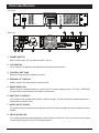
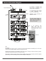
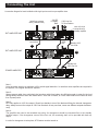
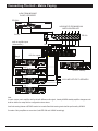
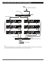
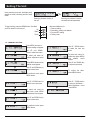
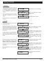
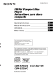
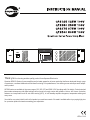
PUBLIC ADDRESS POWER AMPLIFIER ● QUANTUM POWER SERIES
Thank you for choosing another quality product from Amperes Electronics.
Quantum QP2000 Series of power amplifiers are the latest generation of power packs that had been developed through years
of experience, countless feedbacks and limitless fine tuning of its predecessors, thus offering a new and unique audio amplification product.
QP2000 series are available in the power range of 125, 250, 275 and 500W 100V line ratings with 2 hu height. Control parts had
been made contemporary with digital settings via front panel or through custom built software. Various and known protection
features are incorporated such as auto fault sensing (AFS), in built standby amplifier changeover, temperature sensing and
many more.
You shall be very certain that this is the final product you would ever search. We make it available without you paying high price
for a premium product that works exceeding your expectation.
VER 4 / 2015
Parts Identification
Front View
PUBLIC ADDRESS POWER AMPLIFIER ● QUANTUM POWER SERIES
1
2
10
Rear View
4
3
5
6
7
8
12
11
9
1. POWER SWITCH
Mains ac power switch. The unit operates with 220 - 240V ac.
2. LCD DISPLAY
2 X 18 character LCD displaying units parameters and programming instructions.
3. CONTROL BUTTONS
Buttons for various controls and setting up the unit.
4. GROUND LIFT SWITCH
Switch to isolate or link signal ground to equipment body.
5. RS485 DATA LINK
RS485 data port for parameter reading or controls from PC or external triggering panel. For PC link, a USB-RS485
converter shall be required whereas the software is available free.
6. AMP. FAULT CONTACT
A dry contact shall be available if the amplifier is detected as faulty. This allows activation of external changeover or
enable external notification panel.
7. AUDIO INPUT SIGNAL
The amplifier accepts line balanced audio signal and a link XLR connector is available to connect in parallel to the next
amplifier.
8. VENTILATION FAN
It is a variable speed temperature dependant fan with air blows from inside out. The fan can be set to auto or always
on mode. See “Setting Up the Unit” in the following sections.
PAGE 2
Quantum QP2000 Series Power Amplifiers
Parts Identifications ( con’t )
9. AC MAINS INPUT
Operating voltage is 220 to 240V ac ; 50 hertz. Use suitable fuse for replacement.
Recommended Fuse Replacements :
QP2125
QP2250
QP2375
QP2500
5A
5A
6.3A
6.3A
Slow blow fuse is recommended.
10. DC INPUT TERMINAL
24V DC back up supply from batteries are connected to these connectors. Use suitable cable size to avoid overheating
of cables.
11. AUDIO LINE OUTPUTS
Outputs from the units are available in 100 / 70V line and also for 4 Ohm speakers. At any one time, connect only one terminal.
12. STANDBY AMPLIFIER CONNECTOR
T
QP2000 series are equipped with Auto Fault Sensing feature with Standby Fault Changeover relay incorporated.
Outputs from a standby unit is connected to these terminals and connected to the next duty pack in series. Please
refer to the section “ Connecting Standby Amplifier ”.
Quantum QP2000 Series Power Amplifiers
PAGE 3
General Schematic Diagram
PM1120 PAGING MIC
An example of application with
single source to amplifiers, with
one unit being a standby unit.
INPUTS
line audio
MX2222 Mixer
CH1
CH2
CH3
CH4
CH5
CH6
SOURCE
OFF
MIN
MIN
MAX
MIN
MAX
SIG IN
MIN
MAX
MIN
SIG IN
MAX
SIG IN
MIN
MAX
SIG IN
MIN
SIG IN
MAX
MIN
SELECT
TUNER
CASS
MAX
MAX
CHIME
MIN
For Uninterrupted Paging System
or Matrix application, please
contact us for further details.
POWER
TONE CTRL
MX 2222
SIG IN
OFF
MASTER
EXT INPUT
CD
I
a m pe re s
O
AUX
MAX
MIXER
TREBLE
BASS
SIG IN
MIN
MAX
MUSIC SOURCE
SIG IN
EP1200A E/M Mic
zone
triggering
Application of PC monitoring of
amplifiers is optional.
FIRE
To avoid signal distortion in
looping the audio, usage of
signal distributor (DA2208) is
strongly recommended
QP2000 Amplifier
Duty Unit 1
POWER
UP
QP2500
I
a m per es
O
MENU
DOWN
PUBLIC ADDRESS POWER AMPLIFIER ● QUANTUM POWER SERIES
100V
Duty Unit 2
line
POWER
UP
QP2500
I
a m per es
O
MENU
DOWN
PUBLIC ADDRESS POWER AMPLIFIER ● QUANTUM POWER SERIES
Duty Unit 3
100V
POWER
UP
QP2500
I
a m per es
O
MENU
DOWN
PUBLIC ADDRESS POWER AMPLIFIER ● QUANTUM POWER SERIES
100V
Standby Unit
POWER
UP
QP2500
I
RS485
data
In PC monitoring, each
power
pack
must
be
addressed. Up to a max of 16
nos of power packs can be
monitored.
2
USB-RS485
Converter
a m per es
O
MENU
Optional
DOWN
PUBLIC ADDRESS POWER AMPLIFIER ● QUANTUM POWER SERIES
Zone Selector
100V
ZS 5121
a m pe re s
OVERRIDE
1
2
3
4
5
6
7
SPEAKER ZONE SELECT
8
9
TO SPEAKERS
10
11
12
ALL
CALL
PC with QPM
Software
Note :
Changeover :
Duty amplifier with higher priority for changeover must be placed nearest to the standby unit. ie. first output
connection from standby amplifier must be connected to this unit.
Standby fault changeover only available at 100V line outputs. Thereby to utilise this feature, speaker
connections must be terminated at 100V output terminals.
If the system consists of various ratings of power amplifiers, always allocate standby unit with the highest
power rating, to avoid overloading in the event that changeover takes place.
PAGE 4
Quantum QP2000 Series Power Amplifiers
Connecting The Unit
A connection diagram for basic installation with single input source from pre-amplifier mixer.
Audio from pre-amp
mixer ( balanced line )
24V DC
Fr Battery
Bank
2
100V Line Out
To Zone Selector
3
note on the link
connections for
standby amplifier
DUTY AMPLIFIER UNIT
XLR
connections
1
DUTY AMPLIFIER UNIT
100V
Out
Standby 100V
Line Links
4
Standby Unit
100V Line Out
STANDBY AMPLIFIER
Note 1 :
Loop the audio signal to a maximum of 6 to avoid signal distortion. In case that more amplifiers are required in
the system, use a signal distribution amplifier.
Note 2 :
Always ensure cable size, particularly the incoming cable from battery is sufficient enough to cater for the load
during battery takeover when the mains failed. As a rule of thumb, a 2.5mm cable shall not be linked to more
than 6 power packs.
Note 3 :
AFS only applies to 100V line output. Should you decide to turn of the feature utilising the internal changeover
relay, always connect the output at 100V line terminals. At any one time, never use different outputs simultaneously.
Note 4 :
The amplifier that need to be accorded top priority for changeover should be connected first to the standby
amplifier output. If the changeover occurs at the first unit, the remaining shall not be provided with back up
output.
In order for changeover to take place, AFS feature must be turned on.
Quantum QP2000 Series Power Amplifiers
PAGE 5
Connecting The Unit - Matrix Paging
AUDIO FROM MESSAGE
PLAYER / RECORDER
EP1200A
AUDIO INPUTS FROM MXP2188
MATRIX CONTROLLER
E R 1108
24V DC
P R IO R ITY
IN P U T
audio to amplifier inputs
( balanced line )
IN P U T 8
IN P U T 7
IN P U T 6
IN P U T 5
IN P U T 4
IN P U T 3
IN P U T 2
IN P U T 1
O UTPUT 8
O UTPUT 7
O UTPUT 6
O UTPUT 5
O UTPUT 4
O UTPUT 3
O UTPUT 2
O UTPUT 1
ER1108
24V
AUDIO SIGNAL INPUTS / OUTPUTS
CHANNEL 8
+
-
G
+
CHANNEL 7
SIGNAL
LINK
INPUT
OUTPUT
-
G
+
-
CHANNEL 6
SIGNAL
LINK
INPUT
OUTPUT
LINK OPEN +
-
+
-
G
+
CHANNEL 5
SIGNAL
LINK
INPUT
OUTPUT
LINK OPEN
-
+
-
G
+
CHANNEL 4
SIGNAL
LINK
INPUT
OUTPUT
LINK OPEN
-
INPUT
OUTPUT
LINK OPEN +
-
G
+
-
SIGNAL
LINK
LINK OPEN
CHANNEL 3
INPUT
OUTPUT
+
-
G
+
-
CHANNEL 2
SIGNAL
LINK
+
-
SIGNAL
LINK
INPUT
OUTPUT
LINK OPEN
G
+
-
LINK OPEN
CHANNEL 1
OUTPUT
+
-
INPUT
G
+
-
STANDBY FAULT
CONT.
OUTPUT
3A NO
MAX
- G
+
AX3800
AMP. AUTO FAULT
CHANGEOVER
100V line outputs
Duty 6
Duty 5
CHAN. 2
ON
CHAN. 3
ON
CHAN. 4
ON
CHAN. 5
ON
CHAN. 6
ON
CHAN. 7
ON
CHAN. 8
ON
HIGH
CASCADE RS 485
CHAN. 1
ON
LOW
IN+
STANDBY
AMP
IN-
IN+
IN-
IN-
OUT+
OUT+
CHANNEL 1
OUT-
OUT-
IN+
IN-
CHANNEL 2
IN+
IN-
OUT+
CHANNEL 3
OUT-
IN+
OUT-
IN-
CHANNEL 4
OUT+
IN+
OUT-
IN +
IN -
CHANNEL 5
OUT+
OUT -
CHANNEL 6
OUT +
OUT-
IN+
IN-
IN+
IN-
CHANNEL 7
OUT+
OUT-
OUT+
CHANNEL 8
DC 24V
0.5 A
+
-
A
B
ON
SWITCH TO OFF FOR UNUSED CHANNEL
CHANNEL / AMP. DETECTION SWITCHES
-------------------------------
QP2000 - Standby
Duty 2
100V LINE OUTPUTS TO SPEAKERS
Duty 1
Note :
In matrix system, each amplifier shall be fed with different audio signal ; thereby AX3800 standby amplifier changeover unit
shall be used in the setup with the configuration shown above.
Auto fault sensing feature at QP2000 need to be turned off and fault sensing tasks shall be performed by AX3800.
If number of duty amplifiers are more than 8, add ER1108 and AX3800 accordingly.
PAGE 6
Quantum QP2000 Series Power Amplifiers
Connecting The Unit - Uninterrupted Paging
PM SERIES PAGING MIC
amp eres
BGM Inputs
AUX
BGM audio output
Standby
Standby
Duty 1
Duty 1
Duty 2
Duty 2
Paging Output
QP Amplifiers for BGM
QP Amplifiers for Paging
Paging audio output
CD
..
AC 230V 50/60HZ
MX2222
MIXER
BGM Output
ZS5602
SPEAKER ZONE SELECTOR
TO SPEAKERS
Note :
In uninterrupted paging setup, two sets of amplifiers are used; Paging and BGM. Two standby unit shall be required
to serve each set of amplifiers. Auto fault feature need to be turned on at duty units.
Quantum QP2000 Series Power Amplifiers
PAGE 7
Setting The Unit
Upon powering up the unit, the display shall
appear as shown, Initialising and into ready
mode.
Displaying firmware version of
the unit
To begin setting, press the MENU button. Use Next
and Prev button to shift around.
Up
Menu
Down
UP
MENU
DOWN
Showing unit address in bracket,
volume level and temperature
Menus available are for :
1. Channel setting
2. Cascading / setting unit address
3. Fan and AFS setting
4. Factory reset
1.0 CHANNEL SETTING
Press MENU and menu 1
Channel setting will appear.
Use UP and DOWN
button to select sub menu
Use UP / DOWN button
to select the next sub
menu
To select sub menu for
volume adjustment, select
1.1
To select sub menu for
treble level, press MENU
and asterisk would
appear
Press MENU button and an
asterisk would appear
Use UP and DOWN key
to adjust volume level
Use UP and DOWN key to
adjust volume level
To confirm the value, press
MENU button.
Use UP / DOWN button to
select the next sub menu
To select sub menu for
bass level, press MENU
and asterisk would appear
To confirm the value,
press MENU button.
Use UP / DOWN button
to return to Sub Menu 1.
Select Sub Menu 1.4 and
press MENU.
Use UP and DOWN key to
adjust volume level
To confirm the value, press
MENU button.
PAGE 8
Quantum QP2000 Series Power Amplifiers
Setting The Unit
2. CASCADE
Setting the address is used only when all
the amplifiers at to be linked to remote PC
for monitoring. Software is available free,
but an USB-RS485 interface shall be
required.
Among parameters that can be monitored
are volume, temperature, fan and amp
status.
Select Sub Menu 2 for unit addressing
Use UP and DOWN button to select
address number
Press MENU button to confirm
Up to 32 units can be linked together for
monitoring.
3. SETTING
This setting shall be for Auto Fault Sensing
(AFS) and fan control
With Auto Test feature on, Pilot Tone of
20KHz would be generated, and the outputs
shall be monitored. The absence of the tone
shall indicate the amplifier module or the
unit is faulty.
At faulty condition, a dry contact shall be
activated for external triggering. Similarly, a
fault condition data would be sent out via
RS485.
Fan can be set to Auto mode, which the fan
would be automatically turned on upon
reaching 29 Deg C at the heatsink and
would run at temperature dependant speed.
Another mode is to turn on the fan, running
continuously.
We recommend that the fan to be set at
Auto mode.
Select Menu 3
Use UP and DOWN button to select
Sub Menu 3.1 for AFS feature
Press MENU button to select the Sub
Menu and use UP / DOWN button to
turn On or Off.
Once confirm, press MENU and will
revert to Sub Menu. Use UP and
DOWN button to select other Sub
Menu
Use UP and DOWN button to select
Sub Menu 3.2 for fan control
Press MENU button to select the Sub
Menu and use UP / DOWN button to
turn On or Off.
Once confirm, press MENU and will
revert to Sub Menu. Use UP and
DOWN button to select other Sub
Menu
To exit this sub menu, select Back to
Sub Menu 3.
Quantum QP2000 Series Power Amplifiers
PAGE 9
Setting The Unit
4. INFO
This menu provides information on
various parameters such as input and
output level.
Select Sub Menu 4
Output voltage from 100V line terminal
For service purpose : the voltage prior to
step up transformer
Signal input value
Output value in dB
5. SYSTEM
This menu provides information such as
system firmware version and would
enable the unit to reset to factory setting,
erasing all previously set data.
Select Sub Menu 5, press MENU to enter
Firmware version
For resetting the unit to factory default.
For update Firmware to new version
Return
to main menu.
2
6. EXIT
Use this sub menu to exit setting mode.
Select Sub Menu 6, press MENU to enter
Use UP / DOWN button to toggle
between Yes and No and press MENU
button to exit.
PAGE 10
Quantum QP2000 Series Power Amplifiers
Summary of Features
Digital Setting for various parameters with LCD display
Auto fault sensing ( AFS ) with fault contact
Built in standby amplifier changeover
RS485 interface for monitoring and remote setting
Tone and bass controls
Auto fan speed controls
Thermal, fuse, output short circuit protections
High efficiency with low current consumption
Remote monitoring through PMX II LAN via iPX5500 Comm. Box
Technical Specifications
QP2250
QP2375
QP2500
230 / 240V ac or 24V DC back up supply
2.3A
1.3A
3.0A
3.7A
15A
8A
20A
25A
0.31A
0.3A
0.32A
0.35A
1V / 10 K ohm; balanced via XLR female
-40 to 0 dB
250W
125W
375W
500W
31.6V
22.3V
38.7V
44.8V
40 Ohm
80 Ohm
27 Ohm
20 Ohm
70 Hz - 15 KHz @ 1 KHz +/- 3 dB
>70 dB @ 1 KHz, 1V
<0.18 %
Thermal, Short circuit, Overload, Fuse
75 Deg C
Auto temperature controlled fan speed with auto on
LCD with temp, audio level and address
RS485, 19.2 kbps
Internal Pilot Tone, Detection at 15 to 25 secs at 10 secs intervals
Standby amplifier relay activation, fault dry contact
482 x 88 x 335 mm
13.5 kg
12.3 kg
16.5 kg
18.8 kg
15 kg
13.7 kg
18 kg
20.2 kg
QP2125
Power requirement
Power consumption (240V ac)
Current consumption (24VDC)
Standby current (24VDC)
Input signal
Input gain control
Rated output (100V, RMS)
4 ohm output voltage
Output impedance (max load)
Frequency response
S/N ratio
THD + N
Protections
Cut off temperature
Cooling system
Indications
Communication
Fault sensing
Fault detection response
Dimension (W x H x D)
Net Weight (kg)
Gross Weight
Note:
The above specifications are correct at time of printing but subjected to changes without prior notice due to product
improvements.
Quantum QP2000 Series Power Amplifiers
PAGE 11
Warranty Conditions
Only Amperes Electronics Service Centres are allowed to make warranty repairs : a list of Amperes Electronics
Service Centres may be asked for by the purchaser or send directly to Amperes Electronics Sdn Bhd at 70 Jalan
Industri PBP 3, Tmn Perindustrian Pusat Bandar Puchong, 47100, Puchong, Selangor, Malaysia or its authorized
master distributor, TNT Links Sdn Bhd / MyPA Systems Sdn Bhd. This warranty is not valid if repairs are
performed by unauthorized personnel or service centres.
This warranty covers only repairs and replacement of defective parts ; cost and risks of transportation as well as
removal and installation of the product from the main system are for the account of the purchaser. This warranty
shall not extend to the replacement of the unit.
This warranty does not cover damages caused by misuse, neglect, accident of the product as well as using the
product with power supply voltage other than shown on the product, or any other power supply source / adaptor
not recommended by the manufacturer.
This warranty does not cover damages caused by fire, earthquakes, floods, lightning and every cause not directly
related to the unit.
This warranty does not include any indemnity in favor of the purchaser or the dealer for the period out of use of the
unit; moreover the warranty does not cover any damages which may be caused to people and things when using
the product.
This warranty certificate is valid only for the described product, and is not valid if modifications are made on this
certificate or on the identification label applied on the product.
This warranty covers all the material and manufacturing defects and is valid for a period of 12 months from the
date of purchase or for a longer period in countries where this is stated by a national law. In this case, the
extension is valid only in the country where the product is purchased.
Amperes Electronics Sdn Bhd is not obliged to modify previously manufactured products under warranty if the
design changes or improvements are made.
Disclaimer
Information contained in this manual is subject to change without prior notice and does not represent a
commitment on the part of the vendor. AMPERES ELECTRONICS SDN BHD shall not be liable for any loss or
damages whatsoever arising from the use of information or any error contained in this manual.
It is recommended that all services and repairs on this product be carried out by AMPERES ELECTRONICS SDN
BHD or its authorized service agents.
AMPERES series must only be used for the purpose they were intended by the manufacturer and in conjunction
with this operating manual.
AMPERES ELECTRONICS SDN BHD cannot accept any liability whatsoever for any loss or damages caused by
service, maintenance or repair by unauthorized personnel, or by use other than that intended by the manufacturer.
ISO 9001: 2008
Design & Manufacture of Public Address Equipment and Systems
Certificate No. 16895 / A / 0001 / UK / En
AMPERES ELECTRONICS SDN BHD
MADE IN MALAYSIA
Published : March 2015