1
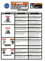
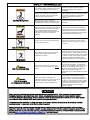
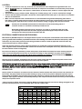
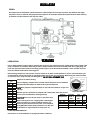
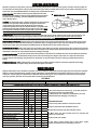
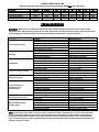
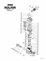
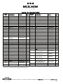
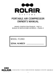
INSTRUCTION MANUAL
MODEL # 13GR30HK30/13GR60HK30
13GRBMHK30
SERIAL #__________________
606 South Lake Street > P.O. Box 346 > Hustisford, WI 53034-0346 > 920.349.3281 > fax 920.349.3691 > www.rolair.com
Starting Instructions
For: Gas Compressors with electric start engines and all
compressors in
cold weather.
1.) Open drain cock which is located on pump “finned”
aftercooler. If this drain cock cannot be located, open drain
cock(s) on bottom(s) of air tank(s).
2.) Please note that engine throttle arm is factory set for proper
RPM. Do not adjust the position of the throttle arm.
3.) Turn kill switch to “on” position, open gas shutoff lever,
engage choke lever. Start engine, disengage choke lever after
engine obtains proper speed. Re-engage choke lever (1/2)
way if needed until engine reaches proper speed. Then
disengage. Close drain cock(s) after engine/pump are cycling
efficiently.
4.) When the temperature drops below 55° F, it may be
necessary to use lighter weight oils in the engine and pump.
Always use straight weight non-detergent oil in the pump.
(30 wt. for 55° F and above)
(20 wt. for temperatures between 32 and 55° F)
(10 wt. for temperatures between 0 and 32° F)
**A 5W-30 detergent oil may be used in the engine when the
temperature drops below 32° F.
STATIONARY
AIR COMPRESSOR
MANUAL
INSTALLATION ~ OPERATION ~ MAINTENANCE
WARNING
COMPRESSOR DISCHARGE AIR MAY CONTAIN HYDROCARBON
AND OTHER CONTAMINANTS; THEREFORE, DO NOT USE
DISCHARGE AIR FOR BREATHING.
RECORD OF PERTINENT INFORMATION
Make a permanent record of the model and serial number of your new air compressor here. You’ll save time and
expense by including this reference information when requesting service or replacement parts.
Place & Date of Purchase
Model
Serial #
Volts
Hz
HP
With shut-off valve to outside line(s) closed and tank pressure at 0 PSI, record the amount of time it takes to build tank
pressure in the space provided below. Periodically test your compressor against this pump-up time to determine if it is
operating correctly. If time test is considerably off, contact your local ROLAIR representative to arrange service.
From 0 to _____PSI
Date
Min.
Sec.
From 0 to _____PSI
Date
Min.
Sec.
RECEIVING INSTRUCTIONS
CONGRATULATIONS ON THE PURCHASE OF YOUR NEW ROLAIR COMPRESSOR!
Immediately upon receipt of your air compressor and prior to completely uncrating, the following steps should be taken:
Step 1) Remove box and inspect compressor for damage that may have occurred during shipment. If any damage is
found, demand an inspection from the carrier. Ask the carrier how to file a claim for shipping damages. Freight
damage is not covered by ROLAIR warranty.
Step 2) Insure that adequate lifting equipment is available for moving the air compressor.
Step 3) Record the model number and serial number from the unit nameplate on the front of your owner’s manual. Space
is also provided for pump-up time test to be performed and recorded upon initial start-up of air compressor.
606 South Lake Street > P.O. Box 346 > Hustisford, WI 53034-0346 > 920.349.3281 > fax 920.349.3691 > www.rolair.com
WARNING
The engine exhaust from this product
contains chemicals known to the State of
California to cause cancer, birth defects or
other reproductive harm.
SAFETY WARNINGS
READ AND UNDERSTAND ALL SAFETY WARNINGS BEFORE USING AIR COMPRESSOR
Hazard Level
Potential of Hazard
Serious injury or death may occur from inhaling
compressed air. The air stream may contain
carbon monoxide, toxic vapors, or solid
particles.
Sprayed materials such as paint, stucco,
insecticides, solvents, etc. contain harmful
vapors and poisons that may cause serious
injury or death if inhaled.
Risk of Asphyxiation
Serious injury or death may occur if the
exhaust from gas-powered small engines is
inhaled. Engine exhaust fumes contain
poisonous, carbon monoxide which is odorless
and colorless.
Serious injury or death may occur from an air
tank explosion if the air tanks are not properly
maintained or if modifications, alterations or
repairs are attempted to the air receivers.
Serious injury or death may occur if
modifications are made to the pilot unloader
valve, pressure switch, safety relief valve or
other components that control the tank pressure.
Risk of Bursting
Serious injury may occur if accessories or
attachments are operated above the
manufacturer’s recommended pressure ratings,
causing them to explode or fly apart.
Serious injury or death could occur if the air
compressor is not properly grounded.
Electrical shock may occur if compressor is not
properly operated.
Risk of Electrocution or
Electrical Shock
Serious injury or death may occur if electrical
repairs are attempted by unqualified personnel.
Serious injury or death may result from normal
electrical sparks that occur within the motor
and/or pressure switch.
Risk of Explosion or Fire
Serious injury may occur if a fire is caused by
overheating due to inadequate ventilation or
restrictions to any of the compressors
ventilation openings.
Serious injury or death may occur from a fire or
explosion if spilled gas or vapors come in
contact with hot engine parts and ignite.
How to Avoid Hazard
Never inhale compressed air directly from the
pump, receiver, or from a breathing device
connected to the air compressor.
Operate compressor only in a well-ventilated
area. Use a respirator device and follow the
manufacturer’s recommendations for their
spray equipment. Keep compressor at least 25
feet away from spray equipment.
Operate gas-powered compressors only in a
well-ventilated area. Avoid inhaling engine
exhaust fumes, and never run a small gaspowered engine in a closed building or
confined area without adequate ventilation.
Drain air tanks daily or after each use. Never
drill into, weld, patch or modify the air tanks. If
a leak develops, replace the tank immediately
or replace the entire compressor.
Never make adjustments to the components
that control tank pressure. Do not make
alterations to the factory operating pressure
settings. Check operation of the safety valve
on a regular basis and never operate without a
factory approved safety valve.
Do not use air tools or attachments before
reading the owner’s manual to determine the
maximum pressure recommendations. Never
exceed the manufacturer’s maximum
allowable pressure ratings. Do not use
compressor to inflate small low pressure
objects such as toys.
Always plug compressor into a properly
grounded outlet which provides correct
voltage, proper grounding and adequate fuse
protection.
Never operate air compressor in wet
conditions or outdoors when it’s raining. Do
not allow electric cords to lay in water. Do not
operate with damaged power cord or with
protective electrical covers removed. Do not
touch plug with wet hands. Do not pull on
electric cord to disconnect from the outlet.
Any electrical repairs or wiring performed on
this compressor should only be performed by
authorized service personnel in accordance
with the National and Local Electric Codes.
Always operate compressor in a well-ventilated
area free of combustible materials, gasoline,
flammable solvents or vapors. Always locate
compressor at least 20 feet away from work
area if spraying flammable materials.
Never place objects against or on top of an air
compressor. Always operate air compressor at
least 18” away from any wall or obstruction.
Always operate in a clean, dry and wellventilated area.
Never attempt to fill the gas tank while the
engine is hot or running. Add fuel outdoors in
a well-ventilated area. Do not fill gas tank near
lit cigarettes or near other sources of ignition.
SAFETY WARNINGS (con’t)
Serious injury may occur from moving parts
such as belts, pulleys, flywheels or fans if they
came in contact with you or your clothing.
An electric air compressor with automatic
controls can restart at any time and cause
bodily injury when least expected.
Risk from Moving Parts
Serious injury may occur if repairs are
attempted with damaged, missing or removed
protective guards, shrouds or missing covers.
Serious burn injuries could occur from touching
exposed metal parts such as the compressor
head, copper/braided discharge lines and
engine exhaust muffler during operation, and
even after compressor is shut down for
sometime.
Never operate the air compressor without
protective belt guards installed. Replace
damaged protective covers or guards
immediately.
Always unplug air compressor and drain air
tanks completely before attempting any repairs
or performing maintenance. Never allow
children or adolescents to operate air
compressor.
All repairs to the air compressor should be
made only by authorized or trained service
personnel.
Never touch any of the exposed metal parts
during operation and for an extended period of
time after the air compressor has shut down.
Do not attempt maintenance on the unit until it
has been allowed to completely cool.
Risk of Burn
Serious injury can result from attempting to lift
an object that is too heavy.
Always obtain assistance from others before
attempting to lift any object that is too heavy for
one person.
Risk of Injury from Lifting
Serious injury may occur from loose debris
being propelled at high speeds from the
compressed air stream.
Flying Objects
Warning
Risk of Unsafe Operation
Caution
Risk of Damage to
Air Compressor or Property
Serious injury or death may occur to you or
others if air compressor is used in an unsafe
manner.
Failure to transport or operate the air
compressor properly may result in major repair
expenses. Oil leaks will damage carpets,
painted surfaces, flooring and other items.
Always wear OSHA required “287” safety
glasses to protect the eyes during operation of
the air compressor. Never point the air stream
or tools at any point of your body, other people
or animals. Always turn off the air compressor
and drain tank pressure completely before
attempting maintenance or attaching air tools.
Review and understand all instructions and
warnings in your owner’s manual. Know how
to stop the air compressor. Do not operate
until you are thoroughly familiar with all of the
controls. Do not operate the compressor if
fatigued or under the influence of alcohol or
drugs. Stay alert while operating the
compressor and pay close attention to the task
at hand.
Check oil levels daily and maintain proper oil
levels. Always run compressor in a level,
secure position that keeps it from tipping or
falling during use. Do not operate without an
air filter or in a corrosive environment. Always
transport in a level position and use protective
mats to keep truck beds clean, etc. Check
drain bolts regularly and do not overfill
machinery with oil.
IMPORTANT
Please note that this product may not be equipped with a spark arresting muffler. If the compressor is operated around
flammable materials or agricultural crops, brush, forests, and grasslands an approved spark arrestor must be installed,
maintained and in good working order. An approved spark arrestor is legally required in the State of California under sections
4442 and 4443 of the California Public Resources Code Statute section 130050.
This product contains chemicals, including lead, known to the state of California to cause cancer, birth defects, and other
reproductive harm. Always wash hands after handling this product.
Periodic inspection of in-service pressure-retaining items is mandated in your jurisdiction. In addition to performing these
inspections, your jurisdiction may require or permit insurance companies to provide the mandated inspection service for their
insured. Information for your jurisdiction can be found on the National Board of Boiler and Pressure Vessel Inspectors website
by typing www.nationalboard.org/NationalBoard/Members/ in your web browser.
INSTALLATION
LOCATION:
• Locate the compressor in a cool, dry, clean and well ventilated area with a temperature range between 35° and
105°F. WARNING! Under no circumstances should the air compressor be installed in an area that may be exposed to
a dirty, corrosive atmosphere, toxic vapors or volatile fumes. Do not store toxic, volatile or corrosive agents near the
compressor.
• The intake filter may be remotely located. Enlarge size of intake piping by 1/4” in size for each 10 feet of length.
• Install so that the flywheel/belt guard is at least 18” from an adjacent wall. Allow space on all sides for air circulation
and ease of maintenance.
• Make sure the compressor tank is mounted level on a solid foundation using vibration dampening pads made of
felt/rubber. If vibration pads cannot be located, the skid on which the compressor is shipped may be left on and used
as a mounting base. Solid shims may be used to level unit before bolting or lagging unit to prevent movement.
NOTE:
Contact your local ROLAIR representative for information on level-rite mounting pads or if
excessive vibration or movement is noticed upon initial test run.
When hard-mounting a gas-powered air compressor on a trailer or a truck bed, leave one of the
four mounting bolts looser than the others (slightly beyond hand-tight) to help minimize vibration
and improve the overall performance and life of the unit.
ELECTRICAL CONNECTIONS AND MOTOR WIRING:
Most stationary ROLAIR compressors are shipped without a power cord. All power cords attached to this machine must be
properly grounded and installed by a qualified electrician with knowledge of the National Electrical Code (N.E.C.), OSHA
Code and/or any local/state/provincial codes having precedence. Failure to abide by applicable electrical codes may
result in personal injury or property damage.
Check the electrical supply for voltage, phase and frequency to see that they match the nameplate stampings on the
motor, magnetic starter, solenoids and other controls. Use electrical wires of adequate size to carry the full load current of
the motor without excessive voltage drop.
The motor must always be protected by a starter with properly sized thermal overload(s). The starter should protect the
motor from overheating and burn-out due to an overload, low voltage or single phasing of a 3-phase circuit. Failure to
install the proper starter and overloads will void the motor manufacturer’s warranty. Follow the National Electric Code or
local electric code in providing wiring, fusing and disconnect switches.
After the wiring is completed, momentarily start the motor to make certain that the compressor flywheel rotates in the
same direction as indicated by the direction arrow on the compressor flywheel.
NOTE: An easy way to check for proper rotation is to place a piece of paper on the outside of the belt guard cover while the
machine is running. If the piece of paper is blown away, the rotation is incorrect. Consult a qualified electrician to correct
the rotation. Improper rotation will lead to overheating and oil blowing out of the crankcase breather.
PIPING FIT-UP:
Always position air compressor to avoid an excessive amount of tension between the external air lines and connection at
the air tank. The piping should be lined up without having to spring or twist it into position. Adequate expansion loops or
bends should be installed to prevent undue stresses at the compressor resulting from the changes between hot and cold
conditions. Pipe supports should be mounted independently of the compressor and anchored as necessary to limit vibration
and prevent expansion strains.
*Never join pipes or fittings with lead-tin soldering. Welded or threaded steel pipes and cast-iron fittings, designed for the
pressures and temperatures, are recommended. Never use PVC or plastic pipe.
Air
CFM
1-5
10
15
25
30
35
40
60-70
80-100
25
1/2
1/2
1/2
3/4
3/4
3/4
3/4
1
1-1/4
Pipe sizes for compressed air lines
Length of Pipe Lines in Feet
50
75
100
150
200
1/2
1/2
1/2
1/2
1/2
1/2
1/2
3/4
3/4
3/4
3/4
3/4
3/4
3/4
3/4
3/4
3/4
3/4
3/4
1
3/4
3/4
3/4
1
1
3/4
1
1
1
1
1
1
1
1
1
1
1
1
1-1/4 1-1/4
1-1/4 1-1/4 1-1/4 1-1/2 1-1/2
250
1/2
3/4
3/4
1
1
1
1
1-1/4
1-1/2
300
1/2
3/4
3/4
1
1
1
1
1-1/4
1-1/2
Check all piping and fittings regularly to avoid leaks in the system.
INSTALLATION
(con’t)
PIPING:
The compressed air distribution system should be of sufficient pipe size to keep the pressure drop between the supply
and point of use to a minimum. All piping should be sloped to an accessible drain-point. Outlets should be taken from top
of mainline so that moisture will not enter the outlet.
LUBRICATION:
OPERATION
Prior to daily operation, make a habit of checking the oil level in your compressor pump. A sight gauge on the outside of the
pump’s crankcase is provided to make the job easier. Always maintain the oil level to read 2/3 full on the sight gauge. Oil
levels over this amount will result in oil blowing past the rings or out of the crankcase breather. Lower amounts of oil will
result in insufficient lubrication of moving parts.
Reciprocating compressors will consume a certain amount of oil under normal operation. If you are concerned about your
oil consumption, monitor and record oil consumption daily and consult your local dealer. When filling your crankcase with
oil, be sure to use a single viscosity, non-detergent oil. DO NOT USE A DETERGENT OIL!!
Oil Capacity
(oz.)
K8
12
K11
17
K12
15
K17
34
K18
34
K22
61
K23
61
K24
61
K25
61
K28
61
K30
47
K35
47
K50
59
K60
98
K70
98
K100 127
Check the oil before starting.
Prior to shipping, complete units are filled with oil and tested. The oil should be
drained and replaced after an initial break-in period of 50 hours.
NOTE: Bare pumps are shipped without oil. See reference charts for oil type and
capacity.
Proper Oil Level:
Whether you have purchased a complete unit or bare pump, check the oil level
and correct if needed before starting each day.
ISO
Ambient
Viscosity
SAE
@100°F
Viscosity
No.
Temperature
Important: Do not over-fill your pump. It will cause harm.
CS+
SSU
0° - 40°
250-350
46-68
20
After break-in period, use a single grade, non-detergent
40°
80°
450-550
100
30
motor oil with foam, rust and oxidation inhibitors. For
80°
120°
650-750
150
40
maximum performance and service life, we recommend
Under 0°
Consult Factory
using ROLAIR Premium Quality compressor oil. (See your
oil distributor or representative for compressor oil.)
Over 120°
Consult Factory
DO NOT USE DETERGENT OIL!
See chart for oil recommendation in varying temperature conditions.
SYSTEM COMPONENTS
Efficiency and safety are the primary concerns when selecting components for compressed air systems. Products of inferior quality can
not only hinder the performance of the unit, but could cause system failures or bodily harm. Select only top quality components for your
system. Call your local ROLAIR distributor for quality parts and professional advice.
DRIVE PULLEYS: Drive pulleys must be properly aligned and drive belt
tension set to specifications. Improper pulley alignment and belt tension
can cause motor overloading, excessive vibration and premature belt
and/or bearing failure.
DRIVE PULLEY
GUARDS: All mechanical action or motion is hazardous in varying degrees
and needs to be guarded. Guards should be designed to achieve the
required degree of protection and still allow full air flow from the
compressor flywheel across the unit. Guards shall be in compliance with
O.S.H.A. safety and health standards and any state or local codes. When
the compressor is installed, make sure guard side is at least 18” away
from the wall to provide adequate cooling of motor and pump.
CHECK VALVES: Check valves are designed to prevent back-flow of air pressure in the compressed air system (air flows freely in one
direction only.) The check valve must be properly sized for air flow and temperature. Do not rely upon a check valve to isolate a
compressor from a pressurized tank or compressed air delivery system during maintenance procedures!
MANUAL SHUT-OFF VALVES: Manual shut-off valves block the flow of air pressure in either direction. This type of valve can be used to
isolate a compressor from a pressurized system, provided the system is equipped with a safety relief valve capable of being manually
released. The safety relief valve should be installed between the manual shut-off valve and the compressor.
SAFETY RELIEF VALVES: Safety relief valves aid in preventing system failures by relieving system pressure when compressed air reaches
a determined level. A check valve and safety relief valve are required in all compressed air systems. Safety relief valves are preset by the
manufacturer and under no circumstances should the setting be changed.
PRESSURE SWITCHES: The pressure switch detects the demand for compressed air and allows the motor to start. When the demand is
satisfied, the unit stops and unloads the head pressure with a short hissing noise. Engine driven units use a pilot valve instead of a
pressure switch. It will discharge compressed air to atmosphere or open the intake valve upon reaching a predetermined pressure
setting.
PRESSURE VESSELS: ASME coded pressure vessels must not be modified, welded, repaired, reworked or subjected to operating
conditions outside the nameplate ratings. Such actions will negate code status.
MAINTENANCE
Regular maintenance insures trouble-free operation. Your new compressor represents the finest engineering and construction available.
However, even the finest machinery requires periodic maintenance. A good maintenance program will add years of service to your air
compressor. The following is recommended as a minimum maintenance program. For your protection, disconnect power supply after
each day’s operation and drain air from system before performing any maintenance.
OIL TABLE
Temperature
0-40°
40° & Above
NON-DETERGENT – Straight Weight
10WT*
30WT*
*For maximum performance and service life, we recommend using ROLAIR Premium Quality compressor oil.
Recommendation
Daily
Check Oil Level
X
Drain Moisture from Tank(s)
X
Inspect Air Filter(s)
X
Check for Unusual Noise or Vibration
X
Inspect Belt Guard
X
Check for Air or Oil Leaks
X
Weekly
Monthly
Quarterly
*Check and retorque (see chart on pg. 7) only after pump has
completely cooled to room temperature.
**Always make sure crankcase vent (breather) is free and
unobstructed when changing or checking oil.
MAINTENANCE HINTS:
1) Use a soap/water solution to check for air leaks.
Clean Exterior of Air Compressor
X
Check Condition of Vibration Pads
X
2) Never clean filters with a flammable solvent.
Tighten/Retorque Bolts*
X
3) Retorque head bolts only after pump has cooled.
Check Belt Tension
X
Check Operation of Safety Valve
X
Change Compressor Oil**
4) Move motor 1/4" and roll belts back on to increase belt
tension on electric units.
X
Clean/Change Air Filter
X
Perform Pump Up Time Test
X
5) Never weld on air tank(s).
Check Operation of System Controls
X
Check Air Tanks for Dents/Leaks
X
6) Use heat to loosen Loctite seal on drain valves, engine
pulleys and flywheels before attempting to remove.
TORQUE CHART (INCH/LBS)
Determine pump type using suffix of model number (Example: V5180K30 uses a K30 pump.)
Pump Type
Head Bolts
Cylinder Bolts
Bearing Carrier Bolts
Connecting Rod Bolts
Flywheel
K17/K18
243
182
130
121.5
382
K24/K25
243
182
130
121.5
382
K28
347
330
130
121.5
477
K30
347
330
130
173.6
477
K35
347
330
130
173.6
477
K50
694
521
165
217
607
K60
347
330
165
217
607
K100
694
521
165
199.7
694
TROUBLESHOOTING
WARNING - Make sure you completely understand all of the safety warnings and operation of each system control
component before attempting any maintenance or repair. Always drain the tank pressure completely, make sure the power
cord is unplugged, and unit has time to cool before performing any maintenance or service operations.
PROBLEM
Low discharge pressure
Knocking
Overheating
Excessive starting/stopping
Excessive belt wear
Oil in discharge air or
oil blowing out of
crankcase vent
Water in crankcase
(Oil appears milky in color)
Motor/compressor fails
to attain speed
CAUSE
Air leaks
Restricted air intake
Loose/slipping belt(s)
Compressor too small
Blown gasket
Broken valves/worn rings
Loose pulley/flywheel
Loose belt(s)
Lack of oil in crankcase
Internal pump problem
Poor ventilation
Dirty cooling surfaces
Incorrect flywheel rotation
Blown gasket(s)
Broken valves
Excessive air leaks
Unit too small for application
Air storage capacity too small
Motor pulley or flywheel out of alignment
Flywheel/pulley wobble
Improper belt tension
Wrong oil viscosity
Improper flywheel rotation
Crankcase overfilled
Obstructed crankcase breather
Inadequate ventilation
Restricted air intake
Worn piston rings
Infrequent cycling
Incorrect or inferior oil
Loose belts
Low voltage
Improper wiring
Defective check valve
Motor overload
Inoperable relief valve
SOLUTION
Correct air leaks
Clean or replace intake element
Adjust belt tension
Perform pump-up time test
Replace head gaskets
Replace valve/rings
Tighten appropriate item
Adjust belt tension
Add oil
Take pump in for service
Relocate air compressor
Clean compressor
Contact an electrician
Replace head gaskets
Replace valve/head gaskets
Correct air leaks
Add/replace air compressor
Add reserve air tank
Reposition pulley or flywheel
Replace appropriate item
Adjust belt tension
Use correct type of oil
Contact an electrician
Drain to proper oil level
Clean or replace breather
Relocate compressor
Clean or replace intake element
Take pump in for service
Install crankcase heater
Use correct type of oil
Correct belt tension
Contact an electrician
Contact an electrician or factory
Replace check valve
Push motor reset
Replace pressure switch
NOTE: Reciprocating compressors consume a certain amount of oil under normal operation. If you are concerned about
your oil consumption, monitor and record oil consumption daily before consulting your dealer. When oil consumption is
normal and what appears to be milky oil is found in your lines, this is caused by small particles of oil, along with water
vapor, condensing in your air lines. To eliminate this problem: Air-Cooled Aftercoolers, Refrigerated Dryers and Filters are
available through your dealer.
Guarantee
Associate Engineering Corporation warrants that all ROLAIR compressors will be free of defects in
material and workmanship for a period of twelve months from the date of initial retail purchase, or
eighteen months from the date of manufacture, whichever may occur first.
Should any failure to conform to this warranty be reported to the company within said period, the
company shall, upon purchaser shipping the compressor to our plant transportation prepaid, correct
such nonconformity by suitable repair or, at its option, furnish a replacement part F.O.B. our plant.
Associate Engineering Corporation shall not be liable for any unauthorized repairs, replacements,
adjustments to the compressors, or the costs of labor performed by the purchaser.
This warranty is expressly in lieu of all other warranties expressed, implied or statutory (including, but
not limited to, warranties of merchantability and fitness for purpose) and of any other obligations,
and/or liabilities on the part of Associate Engineering Corporation. Associate Engineering Corporation
neither assumes nor authorizes any other person to assume for it any other obligations or liability in
connection with or with respect to any compressor.
Associate Engineering Corporation shall in no event be liable neither for any consequential, incidental
or special damages nor for the improper selection of any compressor for a particular application.
Quality
Associate Engineering Corporation is devoted to continual quality control and thorough
research of the products we build. It is our creed to give you, the user, all of the
experience and engineering available in the production of every piece of equipment we
produce.
Our line covers the complete needs of today’s varied air requirements. Rely on ROLAIR for
all the newest and finest features that are available for the modern compressor.
606 South Lake Street > P.O. Box 346 > Hustisford, WI 53034-0346 > 920.349.3281 > fax 920.349.3691 > www.rolair.com
5/09
PARTS LIST FOR PMP22K30
Schem.
#
1
2
3
4
5
6
7
8
9
10
11
12
13
14
15
Description
Part #
Qty.
Schem.
#
36
37
38
39
40
41
42
43
44
45
46
47
48
49
50
51
52
53
54
55
56
57
58
59
Description
Part #
Valve Plate
32702750CH
2
Bushing*
31102250CH
Valve LP
32702400CH
4
Piston HP
31203050CH
Gasket
30502280CH
1
Piston Pin HP
31202240CH
Gasket
30502290CH
1
Connecting Rod Assy.
31101990CH1
Cylinder
31602020CH
1
Ring HP
31202210CH
Bolt
37302420CH
6
Ring HP
31202200CH
Washer
37504220CH
6
Ring HP
31203390CH
Ring LP
31202160CH
1
Plug
36506800CH
Ring LP
31202170CH
1
Bolt
37302480CH
Ring LP
31202180CH
1
Connector
3690211ACH
Piston LP
31202190CH
1
O Ring
30502400CH
Piston Pin LP
31202230CH
1
Valve HP
32702390CH
Snap Ring
37602260CH
4
Right Intercooler
32902720CH
Bearing Shell
31102130CH
2
Bolt
37302530CH
Gasket
30502300CH
1
Left Intercooler
32902710CH
3/8” Breather/Oil
O Ring
30502500CH
16
36507050CH
1
Fill Plug
Gasket
30502270CH
17
Bearing
30302140CH
2
Head
31302700CH
18
Gasket
30502310CH
2
Washer
37502320CH
19
Bearing Carrier
30402740CH
1
Bolt
37308060CH
20
Washer
37508130CH
8
Bolt
37302530CH
21
Bolt
37301140CH
8
Aftercooler
32902730CH
22
Sight Gauge
36500140CH
1
Filter Element
431
23
Gasket
30500130CH
1
Silencer/Filter Assembly FS14075
24
Plug
BLSQPL0250
1
KITS
Gasket Set
25
Crankcase
33102030CH
1
K30GASKETS
(3,4,15,18,23,52)
26
Crankshaft
30202000CH
1
27
Oil Seal
30302150CH
1
Ring Set
K30RINGS
(8,9,10,40,41,42)
28
Bearing Carrier
30402800CH
1
Valve Plate Assembly
29
Nut
37403780CH
1
3000VK30
(1,2,3,4,47,52)
30
Washer
37502450CH
1
Piston Assembly LP
31
Flywheel
31003040CH
1
3000PLPK30
(8,9,10,11,12,13)
32
Nut
37402590CH
4
33
Washer
17500230CH
4
Piston Assembly HP
3000PHPK30
(13,37,38,40,41,42)
Connecting Rod
34
31101990CH
2
w/Upper Bushing
35
Bolt
37302460CH
4
*Bushing is not machined to fit piston pin if ordered separate from connecting rod and must be bored to .005”
over O.D. of piston pin after being pressed into place.
Qty.
2
1
1
2
1
1
2
1
6
1
2
2
1
4
1
2
1
1
6
6
2
1
1
1
1
1
1
1
1
606 South Lake Street > P.O. Box 346 > Hustisford, WI 53034-0346 > 920.349.3281 > fax 920.349.3691 > www.rolair.com
5/09