1
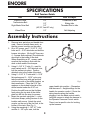
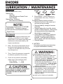
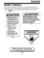
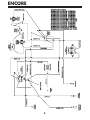
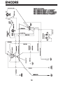
4 8 K200
OPERATORS
MANUAL
ENCORE
Your mower is only as safe as the operator! Operator carelessness or error may result
in serious bodily injury. Improper maintenance of the machine may also result in injury.
Please read and follow these instructions on Safe Operation and be certain that anyone
using this mower fully understands and follows these instructions.
1.
7.
Familiarize yourself with the controls
and know how to stop this mower.
8.
WARNING:
9.
DO NOT allow children to operate the
machine. DO NOT allow any adult to operate
the machine without proper instruction.
2.
3.
4.
5.
6.
10.
Inspect your work area carefully.
Remove debris from the area to be cut.
Keep all bystanders away from the
mowing area.
Avoid contact with moving parts. Keep
hands and feet clear of the mower deck
and all moving parts.
Never direct the discharge of material
toward bystanders nor allow anyone
near the machine while in operation.
Never tamper with safety devices or
guards. If a guard or safety device is
damaged or removed, replace it before
operating the mower.
Handle gasoline carefully: use an
approved gasoline container; fill the fuel
tank to within 1" from the neck with good
quality leaded or unleaded gasoline.
Operator must wear proper shoes and
clothing, which may also include safety
glasses and ear protection.
11.
12.
13.
14.
CAUTION:
Never add fuel to the tank while the engine is
running or hot. ALWAYS WAIT at least five
minutes before refueling and REFUEL WITH THE
ENGINE OFF. KEEP FUEL AWAY FROM
SPARKS OR FLAMES. WIPE AWAY any fuel
spillage BEFORE starting unit. Never fill the fuel
tank indoors. Wipe up any spilled gasoline.
Gasoline is highly flammable - NO SMOKING.
1
Mow only during daylight hours or under
very good artificial light.
Do NOT mow in slippery conditions ,
keep a firm grip on the handle bars,
NEVER RUN.
The safety shield over the grass
discharge must always be bolted in
place and in the down position unless
the grass catcher back plate is
completely installed.
Do NOT leave the operator position
unless the engine has been killed and
blades have stopped.
If a solid object has been hit by the
blades, stop the machine and check for
damage. Repair or replace damaged/
broken part(s) prior to restarting the
engine.
Do NOT allow anyone to stand or walk
on the grass discharge side of the
mower when the mower is in operation.
Do NOT mow close to drop-offs, deep
ditches or other hazards. Mow hillsides
very carefully by mowing across the face
of slopes, not up or down. Do NOT
mow on steep slopes.
To avoid burns, DO NOT TOUCH the
engine or muffler immediately after
operation.
ENCORE
SPECIFICATIONS
Belt Tension Guide
Belt
Inch Deflection
How to Adjust
Engine to Deck
Transmission Belt
Right Blade Drive Belt
1/2”
1/2”
1/2”
(48”,52”, And 60” only)
1/2”
Turnbuckle at Idler
Sliding Idler
Threaded Rod to Idler
Wheel Drive
Self-Adjusting
Assembly Instructions
1.
2.
3.
4.
5.
6.
Remove inner parts box and handle from
crate. Remove outside frame work so
that the mower is setting on the pallet.
On a 36" mower, use 3 – 5/16" X 1 3/4"
bolts and 3 – 5/16" whizlocks and bolt the
bumper into place. (On the 48" there are
4 - bumper bolts required.)The whizlocks
should go to the inside of the deck.
When assembling a 48" mower, make
sure that the bumper is flush with the
deck on both ends of the bumper.
Using 6 – 3/8" X 1" bolts (3 – used for
each caster) and 6 – 3/8" whizlock nuts,
bolt the casters into place. Position
whizlock nuts to the inside of the deck.
Using 2 – 5/16" X 1" bolts with 2 – 5/16"
flat washers and 2 – 15/16" nyloc nuts,
take the shifter lever with grip and bolt
onto the top side of the shifter bracket on
the transmission. Place the 5/16" flat
washers on the slotted hole side of the
shifter bracket under the 5/16" nut.
Position the shift lever so that it slides
freely along the top side of the shifter
plate but still hits the stop for reverse.
Mount the gas tank using the 2 – nylon
hold down straps, pulling tension on the
buckles until secure. Attach the quick
coupler, on the end of the fuel line, to the
bottom of the tank. (See Fig. 1)
Using the remaining 4 - 3/8" X 1" bolts
and the 4 – 3/8" nyloc nuts, bolt the
Fig. 1
upper handle into position. (Remember
that there are 3 – height settings for the
handle for operator comfort.) Route the
wiring harness along the handle,
plugging it into the blade control switch,
using the screws to attach the harness to
the Operator Presence Control switch.
There is not a specific color for hooking
up the harness.
2
ENCORE
Assembly Instructions
7.
8.
Using drive rods provided, turn them into
the 5/16" swivel located in the left and
right hand idler engagement bracket.
Adjust the rods so that there is
approximately 1/4" to 3/8" between the
rod and the bottom of the thumb latch.
Rods should be locked in place by using
4 – hair pin cotters and by placing a 5/
16" flat washer to be inside of the drive
handle between the drive lever and hair
pin cotter. (See fig.2)
With the thumb latches locked in the
neutral position, adjust the brake swivel
until you feel a slight resistance when
hooking it back to the idler assembly.
Remember with thumb locks in the
neutral position, you should be able to
free wheel the machine. When the
thumb locks are rotated all the way to the
lock position, the brake should lock the
wheel. At this time, you may also hook
up the blade engagement rod, adjusting
the length of the rod so the bell crank will
not bottom out in the slot.
Park
Position
1/4" - 3/8"
Neutral
Lock
Drive-Rod
Fig. 2
9.
At this point, oil and fuel engine. Make
sure that the air pressures in the rear
tires are equal at (12 psi). Adjust the
front tire pressures to (20 psi). Your
mower is now ready for use.
Final Check / Adjustment
1.
2.
3.
Adjust the brake control rod to obtain
“free wheeling” with the drive levers in
the neutral position and positive braking
when the drive levers are squeezed close
to the handle grips. Shorten the effective
length of the brake rod to increase
braking.
Check air pressure in drive wheels (12
psi) and caster wheels (20psi). This is
critical for appropriate mower tracking.
Check for proper belt tension (see belt
tension guide).
3.
4.
CAUTION:
Excessive belt tension may cause damage!!
3
Keep a 1/8" to 1/4" clearance between
belt guides and belts. Be sure the drive
control rod is properly adjusted in the
thumb latch. (See Fig 2.)
After a 10 hour “Break-In” period go
through steps 1 thru 3.
Proper adjustments must be maintained
to insure safe, trouble free, long life
operation of the mower. After completing
the foregoing instructions and
recommended procedures you are ready
to put the mower into operation.
ENCORE
Before Operating
Know your machine top to bottom.
11. This unit is equipped with “Operator
Presence Controls” on the upper handle.
When the operator leaves the operator
position removing both hands from the
“Operator Presence Control” levers it will
cause the engine to shutdown.
Make certain all safety standards and
instructions have been fully read and
understood.
Be acquainted with all “SAFETY
INSTRUCTIONS” in this manual – to
start.
1.
Fill the fuel tank and open the fuel valve.
2.
Shift the transmission to neutral.
3.
Blades engagement lever must be in the
“Off” position or back.
4.
Thumb latches need to be in the “Neutral
Lock” position.
5.
Choke the engine as required and start.
6.
After engine is running, push blade
engagement lever forward to engage
blades.
7.
Shift the transmission to the desired gear
(1 thru 4) for mowing, 5th gear is for
transport only.
8.
Squeeze the control levers and push
forward on the thumb latches to unlock
the levers. Slowly release control levers
to engage the drive wheels.
9.
In a normal mode the mower will travel in
a straight line. To turn; squeeze the drive
lever on the side in which you want to
turn.
THIS FEATURE IS FOR YOUR SAFETY!
CAUTION:
Machine must be at a full “STOP” before
shifting from forward to reverse or from
reverse to forward. Failure to do so may
result in personal injury and/or damage
to the transmission.
WARNING:
FAILURE TO FOLLOW THE PREVIOUS
INSTRUCTIONS MAY RESULT IN
SEVERE BODILY INJURY OR
MECHANICAL FAILURE.
10. To STOP forward motion, squeeze both
drive levers, lock thumb latches and shift
the transmission to neutral.
4
ENCORE
HEIGHT ADJUSTMENT
REAR DECK MOUNT IN HIGHEST POSITION
REAR DECK MOUNT IN LOWEST POSITION
(5) spacers on top of caster arm
(4) spacers on top of caster arm
(3) spacers on top of caster arm
(2) spacers on top of caster arm
(1) spacer on top of caster arm
All spacers under caster arm
(5) spacers on top of caster arm = 1 1/2" to 2 3/4"
(4) spacers on top of caster arm = 1 3/4" to 3"
(3) spacers on top of caster arm = 2" to 3 1/4"
(2) spacers on top of caster arm= 2 3/8" to 3 3/8"
(1) spacer on top of caster arm = 2 5/8" to 3 7/8"
All spacers under caster arm = 2 7/8" to 4 1/8"
=
=
=
=
=
=
1 7/8" to 3 1/8"
2 1/8" to 3 3/8"
2 1/2" to 3 3/4"
2 5/8" to 3 7/8"
2 7/8" to 4 1/8"
3 1/4" to 1 1/2"
NOTE: Use 1/4" blade spacers to achieve cutting height between the above measurements.
Rear Deck
Mount Position
Lowest
Caster Arm
Caster Arm
Spacers
Highest
Caster Assy
Blade Spacers
Fig. 4
LUBRICATION / MAINTENANCE
The following recommendations should be used to ensure proper and safe operation of the
mower.
LUBRICATION
(Units Prior to Serial Number 33333)
CAUTION:
Grease Daily:
Idler Arm
Caster Wheels and Caster Pivots
Drive Wheels
Grease Every 100 Hours:
Bell Crank Pivot Bearing
Grease Every 250 Hours:
Cutter Housing Bearings
When greasing Cutter Housing, grease
each one with TWO PUMPS ONLY.
Excessive greasing can force seals out
causing premature bearing failure.
5
ENCORE
LUBRICATION / MAINTENANCE
LUBRICATION
New Blade
(Units After Serial Number 33333)
Grease Daily:
Idler Arm
Caster Wheels and Caster Pivots
Drive Wheels
Grease Every 100 Hours:
Bell Crank Pivot Bearing
25 Degrees
Mower Blades: Check sharpness of
mower blades after every 10 hours of
operation.
To sharpen blades proceed as follows:
• Block the front end of the mower up or
run front end up on ramps
• Remove blade by turning bolt counter
clockwise.
• Sharpen blade with a hand file, electric
grinder or blade sharpener. Wear gloves
and eye protection when sharpening.
Grind blade at original bevel.
• Check balance of blade by positioning
the blade on a nail or blade balance
pedestal. Grind the blade on the end
that is heavier until both sides balance.
• Reinstall blades.
The Peerless Transmission is “LIFETIME
LUBRICATED”. If service is required,
contact an authorized Peerless Dealer or
Repair Center.
MAINTENANCE
1. Engine: For complete maintenance and
operating information for your engine,
please refer to your engine operating and
maintenance manual provided by the
engine manufacturer.
Belts: The drive and deck belts should
be checked and adjusted after the first
10 hours of use and then every 50 hours
from that point on.
3.
Tires: Correct tire pressure is essential
for efficient operation of the mower.
4.
Check tire air pressure periodically.
Inflate tires to the pressures listed:
Drive Wheels
= 12 psi
Caster Wheels = 20 psi
Dangerous!
5.
NOTE:
2.
When Notch Starts
Discard Blade
6. BATTERY:
See battery manufacturer’s instructions
for proper maintenance of battery.
WARNING:
AVOID SERIOUS INJURY OR DEATH:
THE BATTERY CONTAINS SULFURIC ACID.
AVOID CONTACT WITH SKIN, EYES OR
CLOTHING. ANTIDOTE: INTERNAL – DRINK
LARGE QUANTITIES OF WATER OR MILK.
FOLLOW WITH MILK OF MAGNESIA,
BEATEN EGG OR VEGETABLE OIL. CALL A
PHYSICIAN IMMEDIATELY. EYES AND SKIN
– FLUSH WITH WATER AND GET PROMPT
MEDICAL ATTENTION.
BATTERIES PRODUCE EXPLOSIVE GASES,
KEEP SPARKS, FLAMES AND SMOKING
MATERIALS AWAY. VENTILATE WHEN
CHARGING IN AN ENCLOSED SPACE.
WEAR EYE PROTECTION WHEN WORKING
NEAR BATTERIES.
KEEP OUT OF REACH OF CHILDREN.
CAUTION:
DO NOT ADJUST OR CHANGE ATTACHMENTS
UNLESS SPARK PLUG WIRE HAS BEEN
DISCONNECTED AND THE ENGINE HAS
STOPPED.
6
ENCORE
SAFETY DECALS
In order to promote safe operation, Encore Mfg. Co., Inc. supplies safety decals on all
products manufactured. Because damage can occur to safety decals through shipment, use
or reconditioning, Encore will, upon request, provide safety decals for any of our products in
the field at No Charge. Contact your authorized Encore dealer for more information.
363001
363038
363023
363233
7
ENCORE
ENCORE PART #: 363344
BROWN 18 GA.
WIRE HARNESS FOR 32B100E ; 12 HP BRIGGS
WIRE HARNESS FOR 36B100E ; 12 HP BRIGGS
WIRE HARNESS FOR 48B300E ; 16 HP BRIGGS
WIRE HARNESS FOR 52B300E ; 16 HP BRIGGS
WIRE HARNESS FOR 60B300E ; 16 HP BRIGGS
WIRE HARNESS FOR 60B400E ; 18 HP BRIGGS
WIRE HARNESS FOR 48B350EWT ; 16 HP BRIGGS
WIRE HARNESS FOR 48B450EWT ; 18 HP BRIGGS
WIRE HARNESS FOR 52B350E ; 16 HP BRIGGS
WIRE HARNESS FOR 52B450E ; 18 HP BRIGGS
WIRE HARNESS FOR 60B350E ; 16 HP BRIGGS
WIRE HARNESS FOR 60B450E ; 18 HP BRIGGS
WIRE HARNESS
HARNESS FOR WB32B12ES; 12 HP BRIGGS
WIRE HARNESS FOR WB36B12ES; 12 HP BRIGGS
GREEN 18 GA.
MODULE
CONN.
423030
N/O
BROWN 18 GA.
N/C
YELLOW 16 GA.
OPC
SWITCH
363208
NEUTRAL
SWITCH
363207
423017
STARTER RELAY
YELLOW 18 GA.
BLACK 16 GA.
RED /BLACK STP. 18 GA.
20 AMP FUSE
ENGINE KILL
TO BATT.
GROUND
BLACK 16 GA.
RED 14 GA.
ORANGE 18 GA.
8
ENGINE FUEL
SOLENOID
ENGINE
CHARGING
TO BATT.
POS.
WIRE JUNCTION
RED 12 GA.
FUSE BLOCK
RED /BLACK STP. 18 GA.
ORANGE 12 GA.
RED 12 GA.
ORANGE / WHITE 18 GA.
WHITE 16 GA.
423027
IGNITION SWITCH
363164
NEUTRAL
SWITCH HYDRO
363164
BLADE
SWITCH
N/O
BLACK / WHITE 18 GA.
ENCORE
ENCORE PART #: 363371
WIRE HARNESS FOR 48K400 ; 17 HP KAWASAKI
WIRE HARNESS FOR 52K400 ; 17 HP KAWASAKI
WIRE HARNESS FOR 60K400 ; 17 HP KAWASAKI
WIRE HARNESS FOR WB32K13; 13 HP KAWASAKI
WIRE HARNESS FOR WB36K13; 13 HP KAWASAKI
WIRE HARNESS FOR WB36K15; 15 HP KAWASAKI
WIRE HARNESS FOR WB48K15; 15 HP KAWASAKI
WIRE HARNESS FOR WB48K17; 17 HP KAWASAKI
NOTE CHANGES AT CONN .red wire was at B slot
black wire was at E slot
1-21-99 dlm
NOTE CHANGES AT CONN .red wire was at A slot
Yellow wire was at D slot
brown wire was at B slot
black wire was at F slot
green wire was at E slot
12-9-98 dlm
REAR VIEW OF SAFETY
MODULE CONN.
363372
A B C D E F
18 GA GREEN
18 GA BLACK
18 GA RED
TO ENGINE KILL
18 GA BROWN
363208
OPC SWITCH
603060
ON/OFF
KEY SWITCH
18 G
A YE
LLOW
N/O
363207
TRANS.NEUTRAL
SWITCH
363164
BLADE
SWITCH
N/C
18 GA VIOLET
9
E
HIT
AW
18 G
18 GA YELLOW
TO ENGINE GND.
N/O
ENCORE
BLACK / WHITE 18 GA.
BROWN 18 GA.
MODULE
CONN.
N/O
GREEN 18 GA.
N/C
YELLOW 16 GA.
BROWN 18 GA.
NEUTRAL
SWITCH
YELLOW 18 GA.
STARTER RELAY
BLADE
SWITCH
OPC
SWITCH
N/O
NEUTRAL SWITCH
HYDRO
ENCORE PART #: 363373
WIRE HARNESS FOR 48K450EWT ; 17 HP KAWASAKI
WIRE HARNESS FOR 52K450E ; 17 HP KAWASAKI
WIRE HARNESS FOR 52K550E ; 19 OR 20 HP KAWASAKI
WIRE HARNESS FOR 60K550E ; 19 OR 20 HP KAWASAKI
WIRE HARNESS FOR WB48K17ES; 17 HP KAWASAKI
BLACK 16 GA.
ENGINE
KILL
20 AMP FUSE
TO BATT.
GROUND
ORANGE 18 GA.
10
ENGINE
FUEL
ENGINE
CHARGING
TO BATT.
POS.
RED 12 GA.
WIRE JUNCTION
FUSE BLOCK
RED /BLACK STP. 18 GA.
ORANGE 12 GA.
RED 14 GA.
BLACK 16 GA.
IGNITION SWITCH
RED 12 GA.
RED /BLACK STP. 18 GA.
ORANGE / WHITE 18 GA.
WHITE 16 GA.
ENCORE
ENCORE PART #: 363388
WIRE HARNESS FOR 32B100 ; 12 HP BRIGGS
WIRE HARNESS FOR 36B100 ; 12 HP BRIGGS
WIRE HARNESS FOR WB32B12; 12 HP BRIGGS
WIRE HARNESS FOR WB36B12; 12 HP BRIGGS
REAR VIEW OF SAFETY
MODULE CONN.
363372
A B C D E F
18 GA GREEN
18 GA RED
TO ENGINE GND.
363208
OPC SWITCH
18 GA YELLOW
N/O
363207
TRANS. NEUTRAL
SWITCH
18 GA WHITE
TO ENGINE
KILL
18 GA BROWN
18 GA BLACK
N/C
363164
BLADE
SWITCH
18 GA VIOLET
N/O
11
ENCORE
ENCORE PART #: 603027
WIRE HARNESS FOR 48B300 ; 16 HP BRIGGS
WIRE HARNESS FOR 52B300 ; 16 HP BRIGGS
WIRE HARNESS FOR 52B400 ; 18 HP BRIGGS
WIRE HARNESS FOR 60B300 ; 16 HP BRIGGS
WIRE HARNESS FOR 60B400 ; 18 HP BRIGGS
REAR VIEW OF SAFETY
MODULE CONN.
363372
A B C D E F
18 GA GREEN
18 GA RED
TO ENGINE GND.
363208
OPC SWITCH
18 GA YELLOW
N/O
363207
TRANS.NEUTRAL
SWITCH
18 GA WHITE
TO ENGINE
KILL
18 GA BROWN
18 GA BLACK
N/C
363164
BLADE
SWITCH
18 GA VIOLET
N/O
12
Notes:
ENCORE WARRANTY
This warranty extends to the original retail purchaser only and commences on the date of
original retail purchase. Any part of the Encore commercial mower manufactured by Encore
Mfg. Co., Inc. and found in reasonable judgement of Encore Mfg. Co., Inc. to be defective in
material or workmanship will be repaired or replaced by an authorized Encore Mfg. Co., Inc.
dealer without charge for parts and labor. The Encore mower, including any defective part,
must be returned to an authorized Encore service dealer within the warranty period. The
expense of delivering the mower to the dealer for warranty work and the expense of returning
it back to the owner after repair or replacement will be paid by the owner. Should any part
prove to be defective within the two years of original purchase (90 days for rental purposes),
this part will be replace F.O.B. Beatrice, Nebraska, without charge, provided, the defective part
is returned to us transportation charges prepaid. Return Authorization is not required for
cutter housings, electrical components, hydraulic components or belts. Return Authorization
is required for all other components. The responsibility of Encore Mfg. Co., Inc. in respect to
claim is limited to making the required repair or replacements, and no claim of breach of
warranty shall be cause for cancellation or recession of the contract of sale of any Encore
mower. Proof of purchase will be required by the dealer to substantiate any warranty claim.
All warranty work must be performed by an authorized Encore service dealer. This warranty is
limited to two years from the date of original retail purchase for any Encore mower that is used
for commercial purposes or 90 days rental. This warranty DOES NOT cover any Encore
mower that has been subject to misuse, neglect, negligence, accident or that has been
operated in any way contrary to the operating instructions as specified in the Operator’s
Manual. The warranty DOES NOT apply to any damage to the mower that is the result of
improper maintenance, or to any mower parts that have not been assembled or installed as
specified in the assembly instructions. The warranty DOES NOT cover any mower that has
been altered or modified so as to adversely affect the intended use of the product, its
operation, performance or durability. In addition, the warranty DOES NOT extend to repairs
made necessary by normal wear or by the use of parts or accessories which, in the
reasonable judgement of Encore Mfg. Co., Inc. are either incompatible with the mower or
adversely affect its operation, performance or durability. This warranty DOES NOT cover the
engine, which is warranted separately by the engine manufacturer and for different periods of
time. This warranty DOES cover (if equipped) the battery for a period of 90 days. Encore
Mfg. Co., Inc. reserves the right to change or improve the design of any mower without
assuming any obligation to modify any mower previously manufactured. Encore Mfg. Co.,
Inc’s. obligation under warranty is strictly and excessively limited to repair or replacement of
defective parts. Encore Mfg. Co., Inc. DOES NOT assume or authorize anyone to assume
for them any other obligation. Some states do not allow limitations on how long an implied
warranty lasts, so the above limitation may not apply to you. Encore Mfg. Co., Inc. assumes
no responsibility for incidental, consequential or other damages including, but not limited to
expense of delivering the mower to an authorized service dealer and expense of returning it
back to the owner, mechanic’s travel time, telephone or telegram charges, rental of a like
product during the time warranty repairs are being performed, travel, loss of use of the mower,
loss of time or inconvenience. Some states do not allow the exclusion or limitation of
incidental or consequential damages so that above limitation or exclusion may not apply to
you. This warranty gives you specific legal rights which vary from state to state.
ENCORE MFG. CO., INC. CANNOT BE RESPONSIBLE FOR THE WAY, OR CONDITIONS
IN WHICH YOU OPERATE THE MOWER. USE COMMON SENSE AT ALL TIMES.
0403 B ,ENCORE MANUFACTURING CO., INC.
All rights reserved. Contents subject to change.
PREMIER PRO
48K200 - OPERATORS MANUAL
Part Number
933010