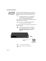
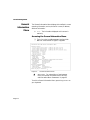
1
Insidecover Page 1 Wednesday, August 13, 1997 12:56 PM
DRAFT
IntraStack™ 6014DSB
User’s Manual
Asanté Technologies, Inc.
821 Fox Lane
San Jose, CA 95131
www.asante.com
1.800.662.9686
August 1997
Part Number: 06-00358-00 Rev. A
Insidecover Page 2 Wednesday, August 13, 1997 12:56 PM
Copyright 1997 by Asanté Technologies, Inc.
All rights reserved. No part of this manual, or any associated artwork, software, product,
design or design concept, may be copied, reproduced or stored, in whole or in part, in any
form or by any means mechanical, electronic, optical, photocopying, recording or otherwise, including translation to another language or format, without the express written consent of Asanté Technologies, Inc.
Printed in the United States of America.
Trademarks
Asanté, IntraStack, and Goldcard are trademarks of Asanté Technologies, Inc. All other
product names are trademarks or registered trademarks of their respective companies.
FCC Information
This equipment has been tested and found to comply with the limits for a Class B digital
device, pursuant to Part 15 of the FCC Rules.These limits are designed to provide reasonable protection against harmful interference when the equipment is operated in a commercial environment.This equipment generates, uses, and can radiate radio frequency energy,
and, if not installed and used in accordance with the instruction manual, may cause harmful interference to radio communications. Operation of this equipment in a residential area
is likely to cause harmful interference, in which case you must correct the interference at
your own expense.
Product Warranty
This IntraStack 6014DSB has a three-year warranty which applies to the original purchaser
of the product. Asanté Technologies, Inc. warrants that this product will be free from
defects in title, materials, and manufacturing workmanship during the warranty period. If
the IntraStack 6014DSB is found to be defective, then, as your sole remedy and as the manufacturer’s only responsibility, Asanté Technologies, Inc. will repair or replace the product
provided that (1) you call Asanté Technologies, Inc. for a Returned Merchandise Authorization (RMA) number, that (2) you clearly write the RMA number on the outside of the package, and that (3) you return it, postage prepaid, during the warranty period.This warranty
is exclusive and is limited to the IntraStack 6014DSB.This warranty shall not apply to
IntraStack products that have been subject to abuse, misuse, abnormal electrical or environmental conditions, or any condition other than what can be considered normal use.
Note: The warranty card must be filed with Asanté Technologies, Inc. within 30 days after
the date of purchase.
Warranty Disclaimers
Asanté Technologies, Inc. makes no other warranties, express, implied, or otherwise,
regarding the IntraStack 6014DSB, and specifically disclaims any warranty for merchantability or fitness for a particular purpose.
The exclusion of implied warranties is not permitted in some states and exclusions specified herein may not apply to you.This warranty provides you with specific legal rights.
There may be other rights you have which vary from state to state.
Limitation of Liability
The liability of Asanté Technologies, Inc. arising from this warranty and sale shall be limited
to a refund of the purchase price. In no event shall Asanté Technologies, Inc. be liable for
costs of procurement or substitute products or services, or for any lost profits, or for any
consequential, incidental, direct damages, however caused and on any theory of liability,
arising form this warranty and sale.These limitations shall apply notwithstanding any failure of essential purpose of any limited remedy.
Table of Contents
List of Figures.................................................................................. ix
List of Tables ................................................................................... xi
Preface .................................................................................xiii
About This Manual .........................................................................xiv
Manual Contents .....................................................................xiv
Document Conventions ...........................................................xv
Audience .................................................................................xvi
Introduction ....................................................................... 1-1
IntraStack 6014DSB .......................................................................1-2
IntraStack Components..........................................................1-3
Expansion Slot..................................................................1-3
MII Expansion Slots ..........................................................1-3
Console Port.....................................................................1-3
10/100 Ports .....................................................................1-3
LEDs..................................................................................1-3
Redundant Power Supply Connector...............................1-3
PCI Slot.............................................................................1-4
Power Supply Connector .................................................1-4
Power Switch ...................................................................1-4
Expansion Units ......................................................................1-5
Configuration/ Management ...................................................1-6
Console/Telnet Management ...........................................1-6
Web Browser Management ..............................................1-6
SNMP-Based Management ................................................1-6
Switching Capacity .................................................................1-7
Chassis Design.........................................................................1-7
Features ...................................................................................1-8
Package Contents....................................................................1-9
Page iii
Tools and Materials ...............................................................1-10
Factory Defaults ....................................................................1-11
Installation ........................................................................ 2-1
Installing the IntraStack 6014DSB..................................................2-2
Installation Guidelines.............................................................2-2
Power Requirements........................................................2-2
Environmental Requirements...........................................2-2
Cooling and Airflow .........................................................2-2
Installation Overview ..............................................................2-3
Rack Mounting/Desktop Placement .......................................2-4
Equipment Rack Installation ............................................2-4
Free-Standing/Desktop Installation .................................2-5
Installing Expansion Units.......................................................2-6
Installing MII Expansion Modules ...........................................2-9
Connecting Power ................................................................2-11
IntraStack Power Sequence............................................2-12
Power-On Sequence ................................................2-12
Power-Off Sequence ................................................2-12
Connecting to the Network ..................................................2-13
10/100 Ports Cabling Procedures...................................2-13
MII Expansion Ports Cabling Procedures.......................2-14
10/100TX Module....................................................2-14
100Base-FX Module .................................................2-14
10Base-FL Module....................................................2-14
Cabling Scenarios ...........................................................2-15
Configuring for Management ................................................2-16
BootP Configuration.......................................................2-16
Console Configuration ...................................................2-17
LED Indicators .................................................................... 3-1
LED Indicators................................................................................3-2
Port LEDs.................................................................................3-3
Indicator Lights .......................................................................3-4
Page iv
Setting Up For Management ........................................... 4-1
IntraStack Management..................................................................4-2
Overview.................................................................................4-2
Management Scenarios Diagram ......................................4-3
Out-of-Band Management........................................................4-4
In-Band Management...............................................................4-6
Console Management ....................................................... 5-1
Console Management.....................................................................5-2
Overview.................................................................................5-2
Configuration Tasks ................................................................5-3
Management Tasks ..................................................................5-3
Local Management Interface ...................................................5-5
Main Menu........................................................................5-5
Accessing a Submenu ................................................5-5
Exiting a Submenu.....................................................5-5
General Information Menu......................................................5-6
Configuration Menu ................................................................5-7
Logging into the Configuration Menu ..............................5-7
Configuration Menu Options.....................................5-8
System Administration Configuration ............................5-10
Changing System Administration Information ........5-11
System IP Configuration.................................................5-12
Changing System IP Information .............................5-13
Bootstrap Configuration.................................................5-14
Changing the Boot Bank Number............................5-17
Executing Software Locally .....................................5-17
Loading Software Remotely.....................................5-18
SNMP Configuration.......................................................5-19
Changing Community Strings..................................5-21
Enabling Traps .........................................................5-21
Adding a Trap Receiver ...........................................5-22
Deleting a Trap Receiver .........................................5-22
Page v
Port Configuration..........................................................5-23
IntraStack System Information ................................5-23
Current Port Settings ...............................................5-24
Enabling or Disabling a Port ....................................5-26
Configuring Full Duplex Mode................................5-26
Configuring Auto Negotiation .................................5-27
Spanning Tree Configuration .........................................5-28
Traffic Monitoring Configuration ...................................5-29
Forwarding Database/Security Configuration ................5-31
Displaying the MAC Address Table .........................5-33
Searching the MAC Address Table...........................5-33
Setting the MAC Address Age Out Time..................5-34
Enabling the Duplicated-IP Trap..............................5-34
Viewing the Trap Log ..............................................5-35
System Clock Configuration...........................................5-36
Setting the Clock .....................................................5-37
TFTP Image File Downloading Configuration................5-38
Performing a Software Upgrade at Runtime............5-40
System Reset Options.....................................................5-41
Resetting the IntraStack...........................................5-42
Scheduling a Reset...................................................5-42
System Log......................................................................5-43
Viewing the System Log ..........................................5-43
Clearing the System Log ..........................................5-44
Set Idle Time Out ...........................................................5-45
Changing the Password..................................................5-46
Statistics Menu ......................................................................5-47
Status Monitoring, Traffic, and Statistics ....................... 6-1
Monitoring the IntraStack ..............................................................6-2
Viewing the Current Operating Information ..........................6-2
Viewing IntraStack System Information..................................6-5
Viewing Statistics ....................................................................6-8
Selecting a Port..........................................................6-9
Monitoring Counters .................................................6-9
Page vi
Resetting Statistics .....................................................6-9
Refreshing Statistics...................................................6-9
Exiting the Statistics Menu ........................................6-9
Counter Descriptions ..............................................6-10
Preparing for Traffic Monitoring...........................................6-12
Advanced Management .................................................... 7-1
Advanced Management..................................................................7-2
Spanning Tree Protocol ..........................................................7-2
How it Works ...................................................................7-2
Enabling/Disabling STP ....................................................7-3
Configuring STP Parameters.............................................7-5
Configuring Switch Priority.......................................7-7
Configuring Timers....................................................7-7
Configuring STP Port Parameters..........................................7-10
Troubleshooting ................................................................. A-1
LED Indicators........................................................................ A-1
Technical Specifications .................................................... B-1
Network Management Platforms Supported....................B-1
LEDs..................................................................................B-1
Connectors .......................................................................B-1
Spanning Tree Support.....................................................B-1
MAC Address Table Size ...................................................B-1
Dimensions.......................................................................B-1
Base (6014DSB) ........................................................ B-1
Expansion unit.......................................................... B-2
Weight ..............................................................................B-2
Base (6014DSB) .........................................................B-2
Expansion unit...........................................................B-2
Power Specifications ........................................................B-2
Environmental Specifications...........................................B-2
Standards Compliance......................................................B-2
Mounting Options ............................................................B-3
Redundant Power Supply.................................................B-3
Page vii
Console Management Map ............................................... C-1
Technical Support .............................................................. D-1
Index .............................................................................. Index-i
Page viii
List of Figures
Figure 1-1
Figure 1-2
Figure 1-3
Figure 2-1
Figure 2-2
Figure 2-3
Figure 2-4
Figure 2-5
Figure 2-6
Figure 2-7
Figure 2-8
Figure 2-9
Figure 2-10
Figure 2-11
Figure 2-12
Figure 3-1
Figure 4-1
Figure 4-2
Figure 4-3
Figure 5-1
Figure 5-2
Figure 5-3
Figure 5-4
Figure 5-5
Figure 5-6
Figure 5-7
Figure 5-8
Figure 5-9
Figure 5-10
IntraStack 6014DSB front panel . . . . . . . . . . . . . . . . . . 1-2
IntraStack 6014DSB back panel . . . . . . . . . . . . . . . . . . 1-2
IntraStack 6014DSB and 6016DSE expansion unit. . . . 1-5
Mounting one rack bracket on the IntraStack . . . . . . . 2-4
IntraStack 6014DSB expansion slot . . . . . . . . . . . . . . . 2-6
Inserting an expansion card into the IntraStack. . . . . . 2-7
Installing stack-mounting pins . . . . . . . . . . . . . . . . . . . 2-7
Installing an expansion unit . . . . . . . . . . . . . . . . . . . . . 2-8
MII expansion slot covers. . . . . . . . . . . . . . . . . . . . . . . 2-9
Installing an MII expansion module . . . . . . . . . . . . . . 2-10
Securing an MII expansion module . . . . . . . . . . . . . . 2-10
Connecting the power cord to the IntraStack . . . . . . 2-11
IntraStack 6014DSB cabling scenarios . . . . . . . . . . . . 2-15
Connecting to the Console port. . . . . . . . . . . . . . . . . 2-17
IntraStack Local Management Interface Main Menu . 2-18
IntraStack 6014DSB front panel layout. . . . . . . . . . . . . 3-2
IntraStack management options . . . . . . . . . . . . . . . . . . 4-3
Connecting to the Console port. . . . . . . . . . . . . . . . . . 4-4
Local Management Interface Main Menu . . . . . . . . . . . 4-5
Local Management Interface Main Menu . . . . . . . . . . . 5-5
General Information Menu . . . . . . . . . . . . . . . . . . . . . . 5-6
Configuration Menu . . . . . . . . . . . . . . . . . . . . . . . . . . . 5-7
System Administration Configuration Menu. . . . . . . . 5-10
System IP Configuration Menu . . . . . . . . . . . . . . . . . . 5-12
BootStrap Configuration Menu. . . . . . . . . . . . . . . . . . 5-14
SNMP Configuration Menu . . . . . . . . . . . . . . . . . . . . . 5-19
Port Management Menu . . . . . . . . . . . . . . . . . . . . . . . 5-23
Traffic Monitoring Configuration Menu . . . . . . . . . . . 5-29
Forwarding DB/Security Configuration Menu . . . . . . 5-31
Page ix
Figure 5-11
Figure 5-12
Figure 5-13
Figure 5-14
Figure 5-15
Figure 5-16
Figure 5-17
Figure 5-18
Figure 6-1
Figure 6-2
Figure 6-3
Figure 6-4
Figure 7-1
Figure 7-2
Page x
System Clock Configuration Menu . . . . . . . . . . . . . . . 5-36
Image Downloading Menu . . . . . . . . . . . . . . . . . . . . . 5-38
Reset Menu . . . . . . . . . . . . . . . . . . . . . . . . . . . . . . . . . 5-41
System Log Menu . . . . . . . . . . . . . . . . . . . . . . . . . . . . 5-43
System Log Display . . . . . . . . . . . . . . . . . . . . . . . . . . . 5-44
Current Idle Time Out command line . . . . . . . . . . . . 5-45
Set Idle Time Out command line . . . . . . . . . . . . . . . . 5-45
Set Password command line. . . . . . . . . . . . . . . . . . . . 5-46
General Information Menu . . . . . . . . . . . . . . . . . . . . . . 6-2
Port Management Menu . . . . . . . . . . . . . . . . . . . . . . . . 6-6
Statistics Menu . . . . . . . . . . . . . . . . . . . . . . . . . . . . . . . 6-8
Traffic Monitoring Configuration Menu . . . . . . . . . . . 6-13
Spanning Tree Configuration Menu . . . . . . . . . . . . . . . 7-4
Spanning Tree Port Configuration Menu . . . . . . . . . . 7-10
List of Tables
Table 1-1
Table 1-2
Table 2-1
Table 2-2
Table 2-3
Table 2-4
Table 2-5
Table 3-1
Table 3-2
Table 4-1
Table 5-1
Table 5-2
Table 5-3
Table 5-4
Table 5-5
Table 5-6
Table 5-7
Table 5-8
Table 5-9
Table 5-10
Table 5-11
Table 5-12
Table 5-13
Table 6-1
Table 6-2
Table 6-3
Table 7-1
Table 7-2
Tools and Materials Required.....................................1-10
Factory Default Settings .............................................1-11
Installation Overview ...................................................2-3
10/100 Ports Cable Guidelines...................................2-13
10/100TX MII Module Cable Guidelines....................2-14
100Base-FX MII Module Cable Guidelines ................2-14
10Base-FL MII Module Cable Guidelines ....................2-14
Port LED Descriptions..................................................3-3
Indicator Light Descriptions ........................................3-4
Management Options ...................................................4-2
Configuration Tasks .....................................................5-3
Management Tasks .......................................................5-3
Configuration Menu Options .......................................5-8
System Administration Configuration Menu Settings 5-10
System IP Configuration Menu Settings .....................5-12
Bootstrap Configuration Menu Settings .....................5-15
SNMP Configuration Menu Settings ...........................5-20
Port Management Menu Settings................................5-24
Traffic Monitoring Configuration Menu Settings .......5-30
Security Configuration Menu Settings........................5-32
System Clock Configuration Settings .........................5-36
Image Downloading Menu Settings ...........................5-39
Reset Menu Settings ...................................................5-41
General Information Menu Parameters ........................6-3
IntraStack System Information .....................................6-6
Statistics Counters Descriptions.................................6-10
Spanning Tree Configuration Menu Settings................7-5
Spanning Tree Port Configuration Menu Settings......7-11
Page xi
DRAFT
Preface
This section provides an overview of the IntraStack 6014DSB
User’s Manual. It describes its chapters, document
conventions, and intended audience.
This chapter contains the following sections:
❏
Chapter Contents — page xiv
❏
Document Conventions — page xv
❏
Audience — page xvi
Preface
About This Manual
Manual
Contents
This manual introduces the IntraStack 6014DSB Ethernet
switch. It describes the switch’s installation, configuration,
troubleshooting, and available network management functions.
This manual is divided into the following chapters and
appendices:
Chapter/Appendix
1
Introduction
Describes the IntraStack 6014DSB, its
package contents, features, switching
capacity, management options, and factory
defaults.
2
Installation
Describes the steps required to install the
IntraStack, connect it to the network, and
configure it for management. This chapter
also describes how to install expansion units
and MII expansion modules.
3
LED Indicators
Describes how to monitor the IntraStack’s
front panel LEDs.
Setting Up For
Management
Describes the management options available
with the IntraStack and how to connect to the
switch with those options.
Console
Management
Describes how to perform some basic
management functions using the IntraStack’s
Local Management Interface.
Status
Monitoring,
Traffic, and
Statistics
Describes how to view the IntraStack’s
current operating information and statistics,
as well as how to prepare the switch for the
connection of an external traffic analyzer.
4
5
6
Page xiv
Description
Document Conventions
Chapter/Appendix
7
Advanced
Management
Appendix A,
“Troubleshooting”
Document
Conventions
Description
Describes how to configure the Spanning
Tree Protocol on the IntraStack.
Provides some troubleshooting tips for
isolating problems with the IntraStack or the
network via the switch’s front panel LEDs.
Appendix B,
“Technical
Specifications”
Provides a list of the IntraStack’s technical
specifications.
Appendix C,
“Console
Management Map”
Provides a one-page map of the IntraStack’s
Local Management Interface.
Appendix D,
“Technical Support”
Provides information for contacting Asanté
Technical Support.
This manual uses the following conventions to convey
instructions and information:
❏
Commands and key words are in boldface font.
∆
Note: Noteworthy information, which contains
suggestions or references to other sections in the
manual, is in this format.
▲
Important: Significant information that calls
attention to important features or instructions
is in this format.
Page xv
Preface
Audience
Page xvi
This manual uses terms and concepts associated with Ethernet
networking and switches; it is recommended that the user of
this manual have a basic working knowledge of local area
networks (LANs).
DRAFT
1
Introduction
This chapter is an introduction to the IntraStack 6014DSB.
It provides an overview of the switch and describes its features,
management and configuration capabilities, switching capacity,
and factory default settings.
This chapter contains the following sections:
❏
IntraStack 6014DSB — page 1-2
❏
IntraStack Components — page 1-3
❏
Expansion Units — page 1-5
❏
Configuration/Management — page 1-6
❏
Switching Capacity — page 1-7
❏
Chassis Design — page 1-7
❏
Features — page 1-8
❏
Package Contents — page 1-9
❏
Tools and Materials Needed — page 1-10
❏
Factory Defaults — page 1-11
Introduction
IntraStack 6014DSB
The IntraStack 6014DSB is a high-performance, stackable 10/
100 Ethernet switch uniquely designed for building highbandwidth workgroups and high-speed network segments.
The IntraStack 6014DSB has 12 fixed 10/100 ports, two
optional Media Independent Interface (MII) expansion slots, 1
future PCI slot, and built-in Web-based network management.
The two MII expansion slots allow for the addition of 10/
100TX, 100Base-FX or 10Base-FL connections. See page 2-9 for
more details.
Expansion Slot
(located on top of switch)
2 Media Independent Interface
(MII) Expansion Slots
12 fixed 10/100Base-T Ports
LEDs
Figure 1-1
PCI slot
IntraStack 6014DSB front panel
Redundant Power Supply Connector
Power Supply Connector
Figure 1-2
Page 1-2
Console Port
for out-of-band
management
connection
IntraStack 6014DSB back panel
Power Switch
IntraStack Components
IntraStack
Components
Expansion Slot
The expansion slot — located on top of the IntraStack
6014DSB’s chassis — is used to attach up to two IntraStack
expansion units, allowing support of up to 46 connections in a
single stack. See “Expansion Units” on page 1-5 for more
information.
MII Expansion Slots
The two Media Independent Interface (MII) expansion slots
allow for the addition of various access modules, including: 10/
100TX, 100Base-FX or 10Base-FL. See “Installing MII Modules”
on page 2-9 for more information.
Console Port
The female DB-9 Console port allows for out-of-band
management and configuration capabilities. See “Out-of-Band
Management” on page 4-4 for more information.
10/100 Ports
The 12 fixed 10/100 ports allow for the connection of 10Base-T
or 100Base-TX (Fast Ethernet) network devices. See
“Connecting to the Network” on page 2-13 for more
information.
LEDs
The LEDs convey the status of each 10/100 port and MII
expansion port (if installed). Power, fan fail, and redundant
power supply status is also displayed. See “LED Indicators” on
page 3-2 for more information.
Redundant Power Supply Connector
The redundant power supply connector can be used to connect
to an external Asanté RPSU 6000 redundant power supply unit
(sold separately).
The RPSU 6000 provides the IntraStack with power in the event
that the switch’s main power connection fails. Refer to the
RPSU 6000’s Installation Guide for more information or to
Appendix C in this manual for part number information.
Page 1-3
Introduction
PCI Slot
The PCI connector provides for high-speed connection of the
switch to existing network backbones, such as FDDI or wide
area links.
▲
Important: The PCI slot is not available with
this release of the IntraStack 6014DSB.
Power Supply Connector
The power supply connector provides the IntraStack’s power
connection. See Appendix C,“Technical Specifications” for
more information.
Power Switch
The power switch turns the IntraStack on or off. See
“Connecting Power” on page 2-11 for instructions on powering
on the IntraStack.
Page 1-4
Expansion Units
Expansion
Units
The IntraStack’s stackable design uses Asanté’s Goldcard™
connector technology to expand the switching system via a
2Gbps (gigabits per second) PCI backplane connector, allowing
up to 46 connections (3 units) in a single stack. The combined
stack functions as a single logical unit.
Initial expansion units for the IntraStack 6014DSB include the
following:
❏
❏
IntraStack 6008FXE — 8 port, 100Base-FX
fiber expansion unit.
IntraStack 6016DSE — 16 port, 10/100TX
expansion unit.
See “Installing Expansion Units” on page 2-6 for a brief
overview on installing an expansion unit.
▲
Important: For more information on a particular expansion unit, refer to the expansion
unit’s Installation Guide.
Figure 1-3 is an example of the IntraStack 6014DSB with an
installed IntraStack 6016DSE expansion unit.
Figure 1-3
IntraStack 6014DSB and 6016DSE expansion unit
Page 1-5
Introduction
Configuration/
Management
The IntraStack can be managed through standard out-of-band
sessions through the Console port, via in-band Telnet sessions,
through the switch’s built-in HTTP server (Web browser
management), or via any SNMP-compatible network
management application.
Console/Telnet Management
The SNMP (Simple Network Management Protocol) is used to
manage the IntraStack. The SNMP agent supports database
objects that are defined in the following management
information bases (MIBs):
❏
❏
❏
MIB II (RFC 1213)
Bridge MIB (RFC 1493)
RMON (RFC 1757) 1 group
The SNMP agent can be accessed via an out-of-band Console
connection or through in-band Telnet sessions. See Chapter 5,
“Console Management” for more information.
Web Browser Management
The IntraStack has a built-in HTTP (Hypertext Transfer Protocol)
server which allows the switch to be managed with any
common World Wide Web browser.
Any networked computer with a functioning Web browser can
access the IntraStack. This provides easy-to-use management
capabilities without the need for additional management
software. Refer to the “IntraStack Web Browser Management
Manual Addendum” for information on using a Web browser to
manage the IntraStack.
SNMP-Based Management
Any SNMP-based network management application, such as
IntraSpection™ Web-based network management software, can
be used to manage the IntraStack. See “SNMP-Based
Management Software” on page 4-7 for more information.
Page 1-6
Switching Capacity
Switching
Capacity
Each 10Base-T/100Base-TX port can forward Ethernet
minimum-sized 64-byte packets at the maximum attainable rate
of 14,880 or 148,000 packets per second (pps).
The IntraStack 6014DSB fully supports the 802.1d transparent
Ethernet bridging standard. IEEE 802.1d compliance provides
automatic address learning, packet filtering, protection against
corrupted frames and fragments, and the Spanning Tree
Protocol.
Chassis Design
The rack-mountable IntraStack 6014DSB chassis is 1.5 RU (rack
units) high. Each expansion unit is 1 RU high.
▲
Important: Do not remove the IntraStack’s
cover. Refer servicing to qualified service personnel.
Page 1-7
Introduction
Features
Page 1-8
The IntraStack 6014DSB has the following features:
❏
12 fixed 10/100 switched ports with RJ-45 connectors; stackable up to three units high for a total of 46
10/100 ports
❏
Two optional MII expansion slots for adding 10/
100TX, 100Base-FX or 10Base-FL modules
❏
One future PCI expansion slot for uplink to existing
backbones, such as FDDI or wide area links
❏
Stackable chassis design expands the switching system via a 2Gbps PCI backplane connector
❏
HTTP server provides Java-enabled front panel view
and SNMP management and configuration via any
Web browser
❏
Telnet (in-band) and Console (out-of-band) management
❏
8,000 MAC addresses per unit
❏
Full duplex support on all ports
❏
NWay™ Auto-Negotiation on 10/100 ports and 10/
100 MII expansion modules
❏
Full 100Mbps wire-speed, non-blocking packet transfers for total throughput of 2Gbps per unit
❏
BootP support
❏
RMON support (1 group)
❏
MIB II, Bridge MIB support
❏
Private MIB support (provides IP-to-port mapping)
❏
802.1d Spanning Tree support
❏
PPP dial-in support for remote access to switched
resources
❏
Store-and-forward switching mode
❏
Advanced diagnostic LEDs
❏
Redundant power supply connector
Package Contents
Package
Contents
The IntraStack 6014DSB is shipped with the following items:
❏
(1) IntraStack 6014DSB Ethernet switch
❏
(1) power cord
❏
(1) Goldcard connector
❏
(2) stack-mounting pins for installing an expansion unit
❏
(2) rack-mounting brackets
❏
(16) standard Phillips screws for attaching the
brackets and rack-mounting the switch
❏
(1) MII opening bracket
❏
(2) MII cover brackets
❏
(1) User’s Manual (this book)
❏
(1) Quick Installation Guide
❏
(1) IntraStack Web Browser Management Manual
Addendum
❏
(1) Registration Card
▲
Important: If you are missing any of the items
listed above, contact the dealer from whom you
purchased the IntraStack 6014DSB.
Page 1-9
Introduction
Tools and
Materials
Some tools and materials that are not supplied with the
IntraStack 6014DSB are needed to connect the switch to an
Ethernet network.
The table below lists the tools and materials required for
connecting devices to the switch’s ports and for rack-mounting
the switch.
▲
Important: For specific instructions on connecting network devices to the IntraStack, see
“Connecting to the Network” on page 2-13.
Table 1-1 Tools and Materials Required
Action
Tool/Material Required
Connecting 10/100
ports
Standard Category 5 UTP straight-through
cable with RJ-45 connectors.
Standard Category 5 UTP cross-over cables
with RJ-45 connectors.
Page 1-10
Connecting 100BaseFX port (optional MII
module)
Dual 62.5/125 micron graded-index
multimode fiber-optic cable fitted with an SC
connector.
Connecting 10BaseFL port (optional MII
modules with SC or
ST connectors)
Dual 62.5/125 micron graded-index
multimode fiber-optic cable fitted with an SC
connector.
Connecting to the
Console port
Straight-through RS-232 cable with a 9-pin
male D-subminiature connector.
Rack-mounting the
switch
Phillips screwdriver for mounting the two
rack brackets on the unit.
Dual 62.5/125 micron graded-index
multimode fiber optic cable fitted with a dual
ST connector.
Factory Defaults
Factory
Defaults
The IntraStack 6014DSB is shipped with the following factory
default settings:
Table 1-2 Factory Default Settings
Configuration
Default Setting
IP address
0.0.0.0
Subnet Mask
0.0.0.0
Default Gateway
0.0.0.0
Switching Mode
Store-and-forward
10/100 Ports
Auto-negotiation enabled
100Mbps speed
Full duplex mode
Spanning Tree
enabled
Page 1-11
DRAFT
2
Installation
This chapter explains how to install, connect, and configure
the IntraStack 6014DSB to work with your network. It also
explains how to install expansion units and MII expansion
modules.
This chapter contains the following sections:
❏
Installation Guidelines — page 2-2
❏
Installation Overview — page 2-3
❏
Installing Expansion Units — page 2-6
❏
Rack Mounting/Desktop Placement —
page 2-4
❏
Installing MII Modules — page 2-9
❏
Connecting Power — page 2-11
❏
IntraStack Power Sequence —
page 2-12
❏
Connecting to the Network — page 2-13
❏
Configuring for Management — page 2-16
Installation
Installing the IntraStack 6014DSB
Installation
Guidelines
▲
Important: Before installing the IntraStack
6014DSB, carefully review the following guidelines.
Power Requirements
The source electrical outlet should be installed near the switch,
be easily accessible, and be properly grounded.
Make sure the power source adheres to the following
guidelines:
❏
❏
❏
Voltage range: 100 to 240 VAC
Frequency range: 60/50 Hz
Maximum current range (6014DSB base unit): 2 A
Environmental Requirements
The IntraStack 6014DSB must be installed in a clean, dry, dustfree area with adequate air circulation to maintain the following
environmental limits:
❏
❏
Temperature: 0° to 45° C
Relative Humidity: 5% to 85% non-condensing
Avoid direct sunlight, heat sources, or areas with high levels of
electro-magnetic interference.
Cooling and Airflow
The IntraStack 6014DSB has two internal fans that cool the
interior by drawing air through vents on one side and forcing
heated air out through holes on the other side.
▲
Page 2-2
Important: Do not restrict air flow by covering or
obstructing air vents on the sides of the chassis.
Installation Overview
Installation
Overview
The table below describes the steps needed to install the
IntraStack 6014DSB. The steps that are optional are labeled
“optional”; the steps that are required are labeled “required.”
The sections that follow explain each step in detail.
To install the IntraStack 6014DSB:
Table 2-1 Installation Overview
Step
1
(required)
Action
Open the box and check the contents.
See “Package Contents” on page 1-9 for a
complete list of the items included with your
IntraStack 6014DSB.
2
(required)
Install the IntraStack in an equipment rack or
prepare it for desktop placement.
See “Rack Mounting/Desktop Placement” on
page 2-4.
3
(optional)
Install expansion unit(s), if any.
See “Installing Expansion Units” on page 2-6.
4
(optional)
Install MII expansion module(s), if any.
See “Installing MII Modules” on page 2-9.
5
(required)
Connect the power supply.
See “Connecting Power” on page 2-11.
6
(required)
Connect the IntraStack to the network.
See “Connecting to the Network” on page 2-13.
7
(optional)
Configure the IntraStack for management
capabilities.
See “Configuring for Management” on
page 2-16.
Page 2-3
Installation
Rack Mounting/
Desktop
Placement
Equipment Rack
Installation
Page 2-4
The IntraStack 6014DSB can be installed in a standard 19-inch
equipment rack. It can also be placed on a stable horizontal
surface with support capabilities of 12 pounds (5.4 kilograms).
To install the IntraStack in an equipment rack:
▲
Important: Disconnect all cables from the
switch before continuing.
1
2
Place the IntraStack on a flat, stable surface.
Locate a rack-mounting bracket (supplied) and
place it over the mounting holes on one side of
the unit, as shown in Figure 2-1.
Figure 2-1
Mounting one rack bracket on the IntraStack
3
Insert six screws (supplied) into the holes and
tighten with a Phillips screwdriver.
4
Repeat the two previous steps for the unit’s
other side.
5
6
Place the IntraStack in the equipment rack.
Secure the switch by screwing its mounting
brackets to the equipment rack.
Rack Mounting/Desktop Placement
▲
Important: Make sure the switch is supported
until all the mounting screws for each bracket
are secured to the equipment rack. Failure to do
so could cause the switch to fall, resulting in
personal injury or damage to the unit, or both.
The IntraStack is ready for the installation of an expansion unit
(if any). See “Installing Expansion Units” on page 2-6.
If you are not installing an expansion unit at this time, proceed
to “Installing MII Modules” on page 2-9.
If you are not installing an expansion unit or an MII module at
this time, proceed to “Connecting Power” on page 2-11.
Free-Standing/
Desktop
Installation
The IntraStack 6014DSB has four rubber feet on the bottom of
the chassis that allow for free-standing installation of the unit.
For free-standing/desktop placement:
❏
Place the IntraStack on a horizontal surface with
a minimum area of 17.1” x 13.5” (434.3 mm x
342.9 mm) and support capabilities of 12 lbs.
(5 kg.).
Page 2-5
Installation
Installing
Expansion Units
Up to two expansion units can be added to the top of the
IntraStack 6014DSB, allowing up to 46 connections in a single,
logical stack.
The IntraStack’s stackable design uses Asanté’s Goldcard
connector technology to expand the switching system via a
2Gbps PCI backplane connector.
∆
Note: The following section provides an
overview of installing an expansion unit. The
steps use the IntraStack 6016DSE expansion
unit as an example; however, the steps pertain
to all expansion units. For more detailed information on an expansion unit, refer to the unit’s
Installation Guide.
To install an expansion unit:
▲
Important: Make sure the IntraStack 6014DSB
is powered off.
▲
Important: Make sure the IntraStack 6014DSB
is on a flat, stable surface or is properly installed
in an equipment rack.
1
If you are installing the IntraStack system in an
equipment rack, install the rack-mounting brackets on the expansion unit. See “Equipment Rack
Installation” on page 2-4 for instructions.
2
Remove the protective plate from the top of the
IntraStack 6014DSB to expose its expansion slot.
Figure 2-2
Page 2-6
IntraStack 6014DSB expansion slot
Installing Expansion Units
3
Insert the Goldcard connector expansion card
that is included with the IntraStack
6014DSB into the slot, as shown in Figure 2-3.
▲
Figure 2-3
4
5
Figure 2-4
Important: You must use the Goldcard
connector included with the 6014DSB.
This connector is used for the base and middle expansion unit; a smaller Goldcard connector is required between the middle and
top expansion unit. The smaller connector
is included with the expansion unit.
Inserting an expansion card into the IntraStack
Press firmly into place.
Screw the two stack-mounting pins (supplied)
into the holes at the top of the IntraStack
6014DSB, as shown in Figure 2-4.
Installing stack-mounting pins
The stack-mounting pins align and secure the
expansion unit to the 6014DSB base unit.
6
Take the IntraStack expansion unit and remove the
label from the bottom of the unit to expose its slot.
Page 2-7
Installation
7
Carefully place the expansion unit on top of the
IntraStack 6014DSB, ensuring that the unit is
aligned with the stack-mounting pins and that the
Goldcard connector expansion card is properly fitted in the slots. See Figure 2-5.
Figure 2-5
8
9
Installing an expansion unit
Firmly press into place.
Plug one end of the expansion unit’s supplied
power cord into the power connector on the
back of the expansion unit.
▲
Important: Do not power on the expansion unit. See “IntraStack Power
Sequence” on page 2-12 for information
on the switch’s power sequence befor e
powering on the expansion unit.
10 Repeat steps 1-7 to install a third expansion unit.
▲
Page 2-8
Important: The top expansion unit in an
IntraStack stack requires a smaller-sized
Goldcard connector. This connector is
included with the expansion unit.
Installing MII Expansion Modules
Installing
MII Expansion
Modules
The IntraStack has two optional Media Independent Interface
(MII) expansion slots which allow for the addition of various
types of media access modules, including:
❏
❏
❏
10/100Base-TX
100Base-FX
10Base-FL
The MII expansion modules are sold separately and comply
with IEEE 802.3 and 802.3u specifications.
To install an MII expansion module:
▲
Important: The MII expansion modules are
hot-swappable; you can install and/or remove a
module without turning the switch’s power off.
1
Remove the MII opening bracket from the front of
the MII expansion slots (located on the IntraStack’s front panel) by unscrewing the bracket’s
thumbscrew.
IntraStack 6014DSB Front Panel
MII Opening Bracket;
remove by unscrewing
the thumbscrew
Figure 2-6
MII expansion slot covers
After the MII opening bracket is removed, you
will see two MII cover brackets, one covering
each slot.
2
Remove an MII cover bracket from the front of
one of the MII expansion slots.
3
Align the bottom of an MII module with the rails
on the inside of the expansion slot.
Page 2-9
Installation
4
Figure 2-7
Installing an MII expansion module
5
Repeat steps 2 – 4 if you are installing another
MII expansion module.
6
Place the MII opening bracket over the MII
expansion slots.
Figure 2-8
7
Page 2-10
Slide the MII module into the expansion slot
until it stops, then push the module in until it
seats with the connector. See Figure 2-7.
Securing MII opening bracket
Tighten the thumbscrew on the MII opening
bracket’s cover to secure the MII expansion
module(s).
The installation is complete.
For more information on MII expansion modules, refer to the Installation Guide included
with your module.
Connecting Power
Connecting
Power
To connect power to the IntraStack:
▲
Important: Carefully review the power
requirements on page 2-2 before connecting
power to the IntraStack.
1
Plug one end of the supplied power cord into
the power connector on the back of the switch.
Figure 2-9
Connecting the power cord to the IntraStack 6014DSB
2
Plug the other end of the power cord into a
grounded AC outlet.
3
Turn the power switch to the “on” position.
The front panel LEDs blink and the power light
illuminates and remains on.
▲
4
Important: If the power does not come
on, refer to Appendix A,“Troubleshooting.”
Turn the switch’s power off.
The switch is ready to be connected to the network. See “Connecting to the Network” on
page 2-13.
Page 2-11
Installation
IntraStack Power
Sequence
The following power sequence must be followed when an
expansion unit is installed.
Power-On Sequence
1
2
Power on the expansion unit(s) fi rst.
Power on the IntraStack 6014DSB last.
▲
Important: An IntraStack stack will not
function properly if an expansion unit is
powered off within the stack while the
other units remain powered on.
Power-Off Sequence
1
2
Page 2-12
Power off the expansion unit(s) first.
Power off the IntraStack 6014DSB last.
Connecting to the Network
Connecting to
the Network
To connect the IntraStack to an Ethernet network:
1
2
Make sure the IntraStack is not powered on.
3
Power on the IntraStack.
Connect network devices to the switch, following the cable guidelines outlined below.
After the IntraStack is connected to the network
and is powered on, it can be configured for management capabilities. See “Configuring for Management” on page 2-16.
10/100 Ports
Cabling Procedures
The 12 fixed 10/100 ports allow for the connection of 10Base-T
or 100Base-TX network devices. The ports are compatible with
IEEE 802.3 and 802.3u standards.
▲
Important: The IntraStack 6014DSB must be
located within 100 meters of its attached
10Base-T or 100Base-TX devices.
Table 2-2 10/100 Ports Cable Guidelines
Connecting To
Cable Required
Network Station
Category 5 UTP (Unshielded Twisted-Pair)
straight-through cable (100 meters maximum)
with RJ-45 connectors.
Repeater/Hub
Category 5, UTP cross-over cable (100 meters
maximum) with RJ-45 connectors.
Repeater/Hub’s
Uplink port
Category 5, UTP straight-through cable (100
meters maximum) with RJ-45 connectors.
Page 2-13
Installation
MII Expansion Ports
Cabling Procedures
10/100TX
Module
100Base-FX
Module
The optional MII expansion slots allow for the connection of
10/100TX, 100Base-FX (fiber), or 10Base-FL ports.
Table 2-3 10/100TX MII Module Cable Guidelines
Connecting To
Network Station
Category 5 UTP (Unshielded Twisted Pair)
cross-over cable (100 meters maximum) with
RJ-45 connectors.
Repeater/Hub
Category 5, UTP straight-through cable (100
meters maximum) with RJ-45 connectors.
Repeater/Hub’s
Uplink port
Category 5, UTP cross-over cable (100 meters
maximum) with RJ-45 connectors.
Table 2-4 100Base-FX MII Module Cable Guidelines
Connecting To
All Network
Devices
10Base-FL
Module
Cable Required
Dual 62.5/125 micron graded-index multimode
fiber-optic cable with an SC connector.
Table 2-5 10Base-FL MII Module Cable Guidelines
Connecting To
SC Connector
All Network
Devices
ST Connector
All Network
Devices
Page 2-14
Cable Required
Cable Required
Dual 62.5/125 micron graded-index multimode
fiber-optic cable with an SC connector.
Dual 62.5/125 micron graded-index multimode
fiber-optic cable with a dual ST connector.
Connecting to the Network
Cabling Scenarios
The following diagram illustrates some of the various cabling
scenarios available with the IntraStack 6014DSB.
Figure 2-10
IntraStack 6014DSB cabling scenarios
Page 2-15
Installation
Configuring for
Management
To use the IntraStack 6014DSB as a managed switch, it must be
configured with an IP address. This can be accomplished in
one of two ways:
❏
❏
BootP Configuration
automatically using BootP (default)
manually via the Console port
The IntraStack 6014DSB is shipped with BootP support. BootP
allows the switch to be automatically configured with an IP
address when the switch is connected to the network and is
powered on, if your network contains a BootP server
configured with available IP addresses.
▲
Important: BootP configuration only works if
the switch does not have an IP address assigned
to it. By default, the IntraStack is shipped without an assigned IP address.
1
Make sure your network has a BootP server configured with a valid IP address entry for the
IntraStack 6014DSB.
2
When the IntraStack is connected to the network and is powered on, it automatically transmits a BootP request across the network (up to
10 times) until it receives a valid IP address from
the BootP server.
3
After an IP address is received, the switch can
be managed via in-band access. See Chapter 4
for more information.
To verify that the switch received an IP address, use a tool such
as Ping1 to try and access the IntraStack; if you can access the
IntraStack, it is properly configured with an IP address.
See “Bootstrap Configuration” on page 5-14 for more
information on using BootP.
1. Ping is an application that can be used to test whether a remote device is
properly connected to a network.
Page 2-16
Configuring for Management
Console
Configuration
To manually configure the IntraStack with an IP address via the
switch’s Console port, use a VT100 terminal or a VT100 terminal emulator running on a workstation or personal computer
(PC) to connect to the switch’s Local Management Interface.
1
Using a straight-thr ough
RS-232 cable with a 9pin male D-subminiature plug at one end, connect a terminal or workstation (PC) running a terminal emulator to the Console port on the front
of the IntraStack.
Figure 2-11
2
Connecting to the Console port
Make sure both units are powered on.
If using a PC with a terminal emulator, make
sure it is configured with the following terminal
settings:
❏ Bits Per Second: 9600
❏ Data Bits: 8
❏ Parity: None
❏ Stop Bits: 1
❏ Flow Control: None
3
Once connected, the Local Management Main
Menu appears on the terminal screen, as shown
in Figure 2-12.
Page 2-17
Installation
Figure 2-12
4
Type c to open the Configuration Menu.
The “Enter Password” prompt appears.
5
Type your password at the prompt.
6
7
8
▲
9
10
Important: The default password is
Asante. The password is case sensitive.
For information on changing the password,
see “Changing the Password” on page 5-46.
Type i to open the Switch IP Configuration menu.
Type i to select the option “Set IP Address.”
Type the IP address to be assigned to the switch
at the prompt.
▲
Page 2-18
IntraStack Local Management Interface Main Menu
Important: Depending on your network configuration, you may also need to
set subnet mask and default gateway
(router) information for the switch. See
“System IP Configuration” on page 5-12 for
instructions.
Press r etur n.
Type q to return to the Configuration Menu.
The IntraStack is configured with an IP address
and can now be managed via in-band access.
See Chapter 4,“Setting Up For Management.”
DRAFT
3
LED Indicators
This chapter describes the IntraStack 6014DSB’s front panel
layout and explains how to interpret the LEDs and indicator
lights.
This chapter contains the following sections:
❏
LED Indicators — page 3-2
❏
Port LEDs — page 3-3
❏
Indicator Lights — page 3-4
LED Indicators
LED Indicators
The IntraStack 6014DSB has five rows of LEDs on its front panel
that allow for easy and fast troubleshooting. The LEDs convey
the status of each 10/100TX port as well as the status of the MII
expansion ports (if installed). See Figure 3-1.
The IntraStack 6014DSB also has three indicator lights that
convey power, redundant power supply, and fan fail status.
The five rows of port LEDs display:
❏
❏
❏
❏
❏
100Mbps (100Mbps operation)
Max util (maximum utilization)
FDP (full duplex operation)
Data
Link
The three indicator lights display:
❏
❏
❏
Pwr (power)
RPS (redundant power supply)
Fan Fail
Indicator
Lights
Port LEDs
Figure 3-1
Page 3-2
MII LEDs
IntraStack 6014DSB front panel layout
Port LEDs
Port LEDs
The IntraStack has five rows of LEDs. The following table states
their color and meaning.
Table 3-1 Port LED Descriptions
LED
Color
Meaning
100Mbps
green
The port is operating at 100Mbps speed.
Max Util
amber
The port’s receive buffer is full (maximum
utilization).
Note: It is normal to see these LEDs light when
the network is in a state of moderate activity.
FDP
amber
The port is operating in full duplex mode.
Note: Full duplex means that a port can transmit
and receive at the same time.
Data
green
Traffic activity is occurring on the port (transmit
[TX] or receive [RX]).
Note: These LEDs light only during extremely
high periods of network activity.
Link
green
∆
The port is properly connected to a powered-on
node or other network device.
Note: For information on using the frontpanel LEDs to troubleshoot problems with
your network, see Appendix A,“Troubleshooting.”
Page 3-3
LED Indicators
Indicator Lights
The IntraStack has three indicator lights. The following table
states their color and meaning.
Table 3-2 Indicator Light Descriptions
LED
Color
Meaning
Power
green
The IntraStack is receiving electrical power.
RPS
amber
The IntraStack’s connection to its main power
supply has failed and the switch is using the
redundant power supply unit (RPSU 6000), if
installed.
Fan Fail
amber
One, or possibly both, of the IntraStack’s internal
fans has failed.
▲ Important: If this LED lights, contact Asanté
Technical Support (see Appendix D).
Page 3-4
DRAFT
4
Setting Up For
Management
This chapter describes the IntraStack 6014DSB’s management
options and explains how to connect to the switch using those
options.
This chapter contains the following sections:
❏
Overview — page 4-2
❏
Management Scenarios — page 4-3
❏
Out-of-Band Management — page 4-4
❏
In-Band Management — page 4-6
Setting Up For Management
IntraStack Management
Overview
The IntraStack 6014DSB and any attached expansion units can
be managed using any of the following methods:
Table 4-1 Management Options
Method
Type
Description
Console
out-of-band
management
local connection to the IntraStack
via the switch’s Console port
Telnet
(four sessions
maximum)
in-band
management
remote connection over the
network to the IntraStack via a
terminal emulation program
HTTP Server
in-band
management
remote connection to the
IntraStack via a Web browser
SNMP-Based
Network
Management
Software
in-band
management
remote connection to the
IntraStack via any SNMP-based
network management application
such as IntraSpection
This chapter describes how to connect to the IntraStack using
either out-of-band or in-band management, as illustrated in
Figure 4-1.
For information on each management method, refer to the following sections:
❏
❏
❏
Page 4-2
Console/Telnet management — see Chapter 5,
“Console Management.”
HTTP Server management — see the IntraStack
Web Browser Management Manual Addendum.
SNMP-based network management software — see
“SNMP-Based Management Software” on page 4-7.
Overview
Management
Scenarios
The following diagram illustrates the management options
available with the IntraStack 6014SDB.
Figure 4-1
IntraStack management options
Page 4-3
Setting Up For Management
Out-of-Band
Management
Out-of-band network management allows you to configure,
manage, and monitor the IntraStack 6014DSB and each of its
ports. You can perform these functions via the following
method:
❏
By attaching a terminal (or a terminal emulator)
to the IntraStack’s Console port and using the
menu-driven Local Management Interface.
Out-of-band network management is guaranteed even when the
in-band Ethernet network is down.
▲
Important: The IntraStack 6014DSB’s RS-232
port is not supported in this release.
To access the IntraStack Local Management Interface using outof-band management:
1
Figure 4-2
2
Page 4-4
Connect a stand-alone terminal or a PC running
a terminal emulator directly to the IntraStack’s
Console port using a straight-thr ough
RS-232
serial cable with a male connector. See
Figure 4-2.
Connecting to the Console port
Make sure both units are powered on.
Out-of-Band Management
If using a PC with a terminal emulator to connect to the Console port, make sure it is configured with the following terminal settings:
❏ Bits Per Second: 9600
❏ Data Bits: 8
❏ Parity: None
❏ Stop Bits: 1
❏ Flow Control: None
3
Figure 4-3
Once connected, the Local Management Interface Main Menu appears on the screen, as
shown in Figure 4-3.
Local Management Interface Main Menu
See Chapter 5,“Console Management,” for information on using the Local Management Interface to manage the IntraStack.
▲
Important: A password is needed to access
the Configuration Menu. The default password
is Asante. The password is case-sensitive.
Page 4-5
Setting Up For Management
In-Band
Management
In-band network management allows you to manage, control,
and monitor the IntraStack 6014DSB and each of its ports over
the Ethernet network.
You can perform these functions by accessing the IntraStack via
any of the following methods:
❏
By connecting with a terminal emulation program such as Telnet and using the Local Management Interface.
❏
By connecting with any common World Wide
Web browser and using the Web Management
Interface.
❏
By connecting with any SNMP-based network
management application and using its interface.
To manage the IntraStack via in-band management:
1
Make sure the network to which the IntraStack
is connected is up and running.
2
Make sure the IntraStack is configured with
valid IP information.
See “Configuring for Management” on page 2-16.
3
Connect to the IntraStack with a terminal emulator, a Web browser, or any SNMP-based network
management application.
Terminal Emulator
See Chapter 5,“Console Management,” for information on managing the IntraStack 6014DSB
with a terminal emulator.
∆
Page 4-6
Note: All management screens using a terminal emulator are identical to those of the
out-of-band Console interface.
In-Band Management
Web Browser
Refer to the “IntraStack Web Browser Management Manual Addendum” for information on
managing the IntraStack 6014DSB with a Web
browser.
SNMP-Based Management Software
Refer to the software’s User’s Manual for information on managing the IntraSwitch with SNMPbased management software.
Page 4-7
DRAFT
5
Console
Management
This chapter describes how to manage the IntraStack 6014DSB
using the out-of-band Console or in-band Telnet interface.
This chapter contains the following sections:
❏
Overview — page 5-2
❏
Configuration Tasks — page 5-3
❏
Management Tasks — page 5-3
❏
Local Management Interface — page 5-5
❏
General Information Menu — page 5-6
❏
Configuration Menu — page 5-7
❏
❏
Logging into the Configuration
Menu — page 5-7
Statistics Menu — page 5-47
Console Management
Console Management
Overview
The IntraStack’s Local Management Interface is a menu-driven
application that provides for management and configuration of
the IntraStack and each of its ports.
The Local Management Interface can be accessed via two
methods:
❏
❏
Out-of-band connection to the Console port.
In-band connection via a terminal emulator such
as Telnet (four sessions maximum).
▲
Important: Refer to Chapter 4, “Setting Up For
Management” for instructions on how to connect to the Local Management Interface via one
of the methods listed above.
This chapter describes each menu item in the Local
Management Interface as well as how to perform the
configuration and management tasks outlined in Tables 5-1
and 5-2.
Page 5-2
Configuration Tasks
Configuration
Tasks
Management
Tasks
Table 5-1 Configuration Tasks
Configuration Task
Page
Logging into the Configuration Menu
page 5-7
Changing System Administration Information
page 5-11
Changing System IP Information
page 5-13
Changing the Boot Bank Number
page 5-17
Executing Software Locally
page 5-17
Loading Software Remotely
page 5-18
Changing Community Strings
page 5-21
Configuring Full Duplex Mode
page 5-26
Configuring Auto-Negotiation
page 5-27
Setting the Clock
page 5-37
Table 5-2 Management Tasks
Management Task
Page
Enabling Traps
page 5-21
Adding a Trap Receiver
page 5-22
Deleting a Trap Receiver
page 5-22
Enabling or Disabling a Port
page 5-26
Performing a Software Upgrade at Runtime
page 5-40
Displaying the MAC Address Table
page 5-33
Searching the MAC Address Table
page 5-33
Setting the MAC Address Age-Out Time
page 5-34
Page 5-3
Console Management
Management Task
Page
Enabling the Duplicated-IP Trap
page 5-34
Viewing the Trap Log
page 5-35
Resetting the IntraStack
page 5-42
Scheduling a Reset
page 5-42
Viewing the System Log
page 5-43
Clearing the System Log
page 5-44
Setting the Telnet Idle Time-Out Period
page 5-45
Changing the Password
page 5-46
▲
Page 5-4
Important: For information on monitoring
statistics, viewing the switch’s current operating
and system information, or preparing the
IntraStack for traffic monitoring, see Chapter 6,
“Status Monitoring,Traffic, and Statistics.”
Local Management Interface
Local
Management
Interface
After you connect to the Local Management Interface using
either out-of-band Console or in-band Telnet connection as
described in Chapter 4, the Main Menu appears, as shown in
Figure 5-1.
Main Menu
Figure 5-1
Local Management Interface Main Menu
From the Main Menu, you can access three submenus:
❏
❏
❏
General Information — page 5-6
Configuration — page 5-7
Statistics — page 5-47
If you are using Telnet, a fourth option will be available — Close
Connection. This option closes your remote connection to the
IntraStack’s Local Management Interface.
Accessing a
Submenu
Exiting a
Submenu
To access a submenu, type the command letter of the
corresponding option (e.g., type g for General Information).
To exit a submenu, type q. To exit a command line (e.g., the
“Set Password” option in the Configuration Menu), press ctrl-c.
∆
Note: For a one-page map of the Local Management Interface, refer to Appendix C,“Console Management Map.”
Page 5-5
Console Management
General
Information
Menu
The General Information Menu displays the IntraStack’s current
operating information; such as, the switch’s name, IP address,
and boot information.
∆
Note: The information displayed on this screen is
read-only.
Accessing the General Information Menu
❏
Type g from the Local Management Interface Main
Menu. A screen similar to Figure 5-2 appears:
Figure 5-2
▲
General Information Menu
Important: For a description of each parameter on the General Information Menu, see “General Information Menu Parameters” on page 6-3.
To exit the General Information Menu, press the space bar on
your keyboard.
Page 5-6
Logging into the Configuration Menu
Configuration
Menu
The Configuration Menu allows you to manage and configure
the IntraStack and each of its ports.
Logging into the Configuration Menu
1
Type c from the Local Management Interface
Main Menu.
2
Enter your password at the “Enter Password”
prompt, then press return.
▲
Important: The default password when
you first access the Configuration Menu is
Asante. The password is case-sensitive;
enter it exactly as shown.
For information on changing passwords, see
“Changing the Password” on page 5-46.
The Configuration Menu appears, as shown in
Figure 5-3.
Figure 5-3
3
Configuration Menu
From this menu you can access configuration submenus by typing the command letter of the corresponding menu option (e.g., type a for the System
Administration Configuration Menu).
Page 5-7
Console Management
Configuration Menu Options
Table 5-3 provides an overview of each Configuration Menu
item.
Table 5-3 Configuration Menu Options
Menu Item
Description
System Administration
Configuration
Displays and allows you to change the name,
location, and contact information for the
IntraStack.
See “System Administration Configuration” on
page 5-10.
Switch IP Configuration
Displays and allows you to change the
information needed to access the IntraStack
over the network (in-band management).
See “System IP Configuration” on page 5-12.
Bootstrap Configuration
Allows you to change the boot method the
IntraStack uses for loading its software. Also
allows you to change the parameters used for
downloading a new version of runtime
software for the IntraStack.
See “Bootstrap Configuration” on page 5-14.
SNMP Configuration
Displays and allows you to change the
IntraStack’s SNMP (Simple Network
Management Protocol) parameters; such as,
read/write community strings, trap
authentication, and trap receivers.
See “SNMP Configuration” on page 5-19.
Port Configuration
Allows you to manually configure each of the
switch’s ports for speed, connection, link mode,
and auto-negotiation. Also displays an overall
status of the IntraStack system.
See “Port Configuration” on page 5-23.
Spanning Tree Configuration
Displays and allows you to change the switch’s
Spanning Tree parameters.
See “Spanning Tree Configuration” on page
5-28.
Traffic Monitoring
Configuration
Allows you to prepare the IntraStack for traffic
monitoring with an external traffic analyzer.
See “Traffic Monitoring Configuration” on
5-29.
Page 5-8
Configuration Menu
Menu Item
Description
Forwarding DB/Security
Configuration
Allows you to view and search for addresses in
the IntraStack’s MAC Forwarding Table. Also
allows you to set a trap for duplicate IP
addresses and view the trap log.
See “Forwarding Database/Security
Configuration” on page 5-31.
System Clock Configuration
Allows you to set the IntraStack’s real-time
system clock.
See “System Clock Configuration” on page
5-36.
TFTP Image File
Downloading Configuration
Allows you to upgrade the IntraStack’s
software.
See “TFTP Image File Downloading
Configuration” on page 5-38.
System Reset Options
Allows you to reset the IntraStack by
performing a “warm” reboot of the switch.
Also allows you to set the switch for an
automatic reset (up to 24 hours in advance).
See “System Reset Options” on page 5-41.
System Log
Allows you to view the IntraStack’s System
Log.
See “System Log” on page 5-43
Set Idle Time-out
Allows you to set the idle time-out period
when using Telnet to access the IntraStack.
See “Idle Time Out” on page 5-45.
Change Password
Allows you to change the password needed to
access the Configuration Menu.
See “Changing the Password” on page 5-46.
Return to Previous Menu
Exits the Configuration Menu and returns you
to the Local Management Interface Main
Menu.
Page 5-9
Console Management
System Administration Configuration
This menu displays and allows you to change the name,
location, and contact information for the IntraStack.
To access the System Administration Configuration Menu, type
a in the Configuration Menu. A screen similar to Figure 5-4
appears.
Current Settings
Figure 5-4
System Administration Configuration Menu
Current Settings
Table 5-4 explains each setting on the System
Administration Configuration Menu.
For information on using the menu, see:
❏ “Changing System Administration Information” — page 5-11
Table 5-4 System Administration Configuration Menu Settings
Page 5-10
Setting
Description
Switch Name
The name of the IntraStack (up to 64
characters, including spaces).
Switch Location
The location where the IntraStack is physically
located (up to 64 characters, including spaces).
Switch Contact
The name of the person or entity responsible
for the IntraStack (up to 64 characters,
including spaces).
System Administration Configuration
Changing System Administration Information
To change the switch’s name/location/contact information:
1
Open the System Administration Configuration Menu by typing a in the Configuration
Menu.
2
Type the command letter of the item to be
changed in the System Administration Configuration Menu.
3
Type the information at the prompt.
See Table 5-4 for a description of each parameter.
▲
Important: Each parameter is limited to
64 characters, including spaces.
To cancel a selected option, press ctrl-c at
the command prompt.
4
Press return.
The switch’s system administration information is changed.
To quit and return to the Configuration
Menu, type q.
Page 5-11
Console Management
System IP Configuration
This menu displays and allows you to change the information
needed to access the IntraStack over the network (in-band
management).
To access the System IP Configuration Menu, type i in the
Configuration Menu. A screen similar to Figure 5-5 appears.
Current Settings
Figure 5-5
▲
System IP Configuration Menu
Important: By default, each address is set
to 0.0.0.0.
Current Settings
Table 5-5 explains each setting on the System IP
Configuration Menu.
For information on using the menu, see:
❏ “Changing System IP Information” on page 5-13
Table 5-5 System IP Configuration Menu Settings
Page 5-12
Setting
Description
Switch IP Address
The IntraStack’s IP (Internet Protocol) address.
Switch Subnet Mask
The address of the subnet mask on which the
IntraStack is located.
Switch Default Router
The address of the IntraStack’s default router.
System IP Configuration
Changing System IP Information
To change the IntraStack’s IP address, subnet mask, or
default router information:
1
Open the System IP Configuration Menu by
typing i in the Configuration Menu.
2
Type the command letter of the option you
want to change.
3
Type the new address at the prompt.
See Table 5-5 for a description of each
address.
▲
Important: Follow the format: number. number. number. number.
To cancel, press ctrl-c at the command
prompt.
4
Press return.
The switch’s IP information is changed.
To quit and return to the Configuration
Menu, type q.
Page 5-13
Console Management
Bootstrap Configuration
This menu displays and allows you to change the bootstrap
parameters used for loading the switch’s software at startup
and for downloading a new version of software when one is
issued.
To access the Bootstrap Configuration Menu, type b in the
Configuration Menu. A screen similar to Figure 5-6 appears.
Current Settings
Figure 5-6
▲
BootStrap Configuration Menu
Important: The IntraStack’s Load Mode
default setting is Local.
When the IntraStack is first powered on, it loads its software via
one of two methods: locally (via its internal flash memory; this
is the default setting) or remotely (over the network).
Image Banks
The IntraStack has two areas (or “banks”) where its runtime
software is stored:
Page 5-14
❏
Boot Bank — the bank that is used during the
switch’s system boot-up. The switch searches for
valid code in this bank at startup.
❏
Destination Bank — the bank that receives the
new version of runtime code when its downloaded.
Bootstrap Configuration
The Boot Bank and the Destination Bank are each referred to by
a number (1 or 2). To set the banks’ numbers, see “Changing
the Boot Bank Number” on page 5-17.
Current Settings
Table 5-6 explains each setting on the Bootstrap
Configuration Menu.
For information on using the menu, see:
❏ “Changing the Boot Bank Number” —
page 5-17
❏ “Executing Software Locally” — page 5-17
❏ “Loading Software Remotely” — page 5-18
▲
Important: For information on performing a software upgrade, see “Performing a
Software Upgrade” on page 5-40.
Table 5-6 Bootstrap Configuration Menu Settings
Setting
Description
Running Image
Version/Date
The version and compilation date of runtime
code that is currently running on the IntraStack.
This should be the same as the Boot Bank.
Bank 1 Image Version/
Date
The version and compilation date of runtime
code that is currently stored on the IntraStack.
Note: The image bank is where the runtime
code is stored; the IntraStack 6014DSB has two
image banks: Boot Bank and Destination Bank.
Bank 2 Image Version/
Date
The version and compilation date of runtime
code that is currently running on the
IntraStack.
Boot Server IP
The IP address of the boot server providing
BootP/TFTP capabilities on your network.
Boot File Name
The name of the software file and its network
path.
Page 5-15
Console Management
Setting
Description
Boot Mode
The method for requesting the software image
file from the network.
BootP-TFTP — sets the IntraStack to request
an IP address from a BootP server AND to
download the software’s image file through
TFTP (Trivial File Transfer Protocol).
Important: To use this option, the switch’s IP
address must be set to 0.0.0.0 and the Load
Mode must be set to Remote.
TFTP ONLY — sets the IntraStack to only
download the software image file through
TFTP (an IP address is not requested).
Important: To use this option, the switch must
already have an assigned IP address and the
Load Mode must be set to Remote.
Load Mode
The current method for loading the
IntraStack’s software.
Local — executes the software image file from
the switch’s internal flash memory (default
setting; the switch automatically reverts to this
setting after downloading a new software file).
Remote — loads the software image file from
a server on the network.
Important: To use the remote option, you
must select BootP-TFTP or TFTP as the Boot
Mode.
Boot Bank
The number of the image bank being used to
load the IntraStack’s software.
Note: The image bank is where the runtime
code is stored; the IntraStack 6014DSB has
two image banks: Boot Bank and Destination
Bank.
Page 5-16
Bootstrap Configuration
Changing the Boot Bank Number
The IntraStack’s two image banks (Boot Bank and
Destination Bank) are each assigned a number (1 or 2).
By default, the Boot Bank is assigned Bank number 1; the
Destination Bank is Bank number 2.
To change the Boot Bank’s number:
1
Open the Bootstrap Configuration Menu by
typing b in the Configuration Menu.
2
Type a in the Bootstrap Configuration Menu
to toggle the Boot Bank from 1 to 2 (or vice
versa).
The Boot Bank’s number is changed. Its new
number is displayed at the top of the screen
(next to Boot Bank:).
The Destination Bank’s number is also
changed; it becomes the number not
assigned to the Boot Bank.
Executing Software Locally
To set the IntraStack to boot (execute its software) locally
from its internal flash memory:
1
Make sure the IntraStack is configured with a
valid IP address.
2
Open the Bootstrap Configuration Menu by
typing b in the Configuration Menu.
3
Type l in the Bootstrap Configuration Menu
to set the Load Mode to Local.
The IntraStack is set to load its software
locally from its internal flash memory. This
occurs each time the switch is powered on
or is reset.
Page 5-17
Console Management
Loading Software Remotely
To set the IntraStack to boot (download its software) over
the network from a remote server:
Page 5-18
1
Open the Bootstrap Configuration Menu by
typing b in the Configuration Menu.
2
Type s in the Bootstrap Configuration Menu
to select the option Set Boot Server IP
Addr ess.
3
Type the IP address of the remote boot
server containing the software image file for
the IntraStack at the prompt, then press
return.
4
5
6
Type r to set the Load Mode to Remote.
7
Press return.
The IntraStack is set to download its software
remotely from the network. This occurs each
time the switch is powered on or is reset.
Type f to select the option Set File Name.
Type the software’s file name and network
path at the prompt.
SNMP Configuration
SNMP Configuration
This menu displays and allows you to change the IntraStack’s
SNMP (Simple Network Management Protocol) parameters.
With these parameters, you can configure the switch’s read and
write community strings, set the switch to generate traps, and
determine which management stations on your network can
receive traps.
To access the SNMP Configuration Menu, type n in the
Configuration Menu. A screen similar to Figure 5-7 appears.
Current Settings
Figure 5-7
SNMP Configuration Menu
Current Settings
Table 5-7 explains each setting on the SNMP Configuration
Menu.
For information on using the menu, see:
❏
“Changing Community Strings” — page 5-21
❏ “Enabling Traps” — page 5-21
❏ “Adding a Trap Receiver” — page 5-22
❏ “Deleting a Trap Receiver” — page 5-22
Page 5-19
Console Management
Table 5-7 SNMP Configuration Menu Settings
Setting
Description
SNMP Read
Community
The IntraStack’s SNMP read community
string.
The read community string is a single word
that defines access rights for reading SNMP
data objects.
The default setting is public.
SNMP Write
Community
The IntraStack’s SNMP write community
string.
The write community string is a single word
that defines access rights for writing SNMP
data objects.
The default setting is private.
Trap Authentication
The status of the SNMP agent to generate
authentication traps.
The default setting is disabled.
SNMP Trap Receivers
The IP addresses of the network management
stations that can receive traps from the switch.
Normally, these addresses are the same as
your network management software systems’
IP address(es).
▲ Important: A maximum of four traps
receivers is allowed.
Page 5-20
SNMP Configuration
Changing Community Strings
To change the IntraStack’s community strings:
1
Open the SNMP Configuration Menu by typing n in the Configuration Menu.
2
Type r to change the read community string
or w to change the write community string.
3
Type a new community string at the prompt.
See Table 5-7 for a description of read and
write community strings.
To cancel a selected option, press ctrl-c at
the command prompt.
4
Press return.
To quit and return to the Configuration
Menu, type q.
Enabling Traps
The IntraStack can be set to generate authentication traps.
Authentication traps are messages sent across the network
to an SNMP network management station. They alert you
when someone without access rights attempts to change
the device’s MIB information.
To set the IntraStack to generate traps:
1
Open the SNMP Configuration Menu by typing n in the Configuration Menu.
2
Type t toggle trap authentication from disabled to enabled.
To cancel, press ctrl-c at the command
prompt.
To quit and return to the Configuration
Menu, type q.
Page 5-21
Console Management
Adding a Trap Receiver
Trap receivers are the network management stations
designated to receive traps from the switch when they
occur.
▲
Important: The maximum number of
trap receivers that can be set is four.
To add a trap receiver entry:
1
Open the SNMP Configuration Menu by typing n in the Configuration Menu.
2
3
Type a to Add a T rap Receiver
.
4
Type the trap receiver’s community string at
the prompt, then press return.
The trap receiver entry is added.
To return to the Configuration Menu, type q.
Type the IP address of the network management station you want to receive traps, then
press return.
To cancel, press ctrl-c.
Deleting a Trap Receiver
To delete a trap receiver entry:
Page 5-22
1
Open the SNMP Configuration Menu by typing n in the Configuration Menu.
2
3
Type d to Delete a T rap Receiver
.
Type the number of the receiving network
management station entry to be deleted,
then press return.
The trap receiver entry is deleted.
To return to the Configuration Menu, type q.
Port Configuration
Port Configuration
This menu allows you to manually configure each of the
IntraStack’s ports and any installed MII modules for speed,
connection, link mode, and auto-negotiation.
It also provides an overview of the IntraStack system’s current
operating status (whether any expansion units are installed and
are operating and the operating status of each of the ports in
the stack).
The default parameters for each of the IntraStack 6014DSB’s
port are:
❏
❏
❏
auto-negotiation — enabled
port speed — 100Mbps
link mode — full duplex
To access the Port Configuration Menu, type p in the
Configuration Menu. A screen similar to Figure 5-8 appears.
IntraStack System Information
Current Port Settings
Figure 5-8
Port Configuration Menu
IntraStack System Information
Table 5-8 on page 5-24 explains the IntraStack system
information. For directions on using this menu to view
IntraStack system information, see “Viewing IntraStack
System Information” on page 6-5.
Page 5-23
Console Management
Current Port Settings
The current port for which statistics are displayed is shown
at the top of the screen (next to “Port Number:”).
Table 5-8 explains each setting on the Port Configuration
Menu.
For information on using the Port Configuration Menu, see:
❏ “Enabling/Disabling a Port” — page 5-26
❏ “Configuring Full Duplex Mode” — page 5-26
❏ “Configuring Auto Negotiation” — page 5-27
Table 5-8 Port Management Menu Settings
Setting
Description
Companion 2
The status of the second installed expansion unit.
Down/Absent — an expansion unit is not operating
or is not installed.
If an expansion unit is installed, port symbols
representing the status of each of the unit’s ports
will be displayed. See the options listed in this table
under “Base Module.”
Companion 1
The status of the first installed expansion unit.
The options are identical to those of Companion 2.
Base Module
The status of the IntraStack 6014DSB (base unit).
This field displays symbols for each of the switch’s
12 ports.
List of Port Symbols:
X — no port exists.
- (negative symbol) — a port exists but there is no
link on the port.
! — the port is disabled.
B — the port is in a blocking state.
S — the port is in a listening state.
R — the port is in a learning state.
+ — the port is in a forwarding state.
Important: Type h “Help for Legends” in the Port
Management Menu for a list of the port symbols.
Port Number
Page 5-24
The number of the port for which parameters are
shown.
Port Configuration
Setting
Description
Fwd Unknown
The status of the port’s ability to forward packets
with an unknown address.
Enabled — the port will forward packets with
unknown addresses.
Disabled — the port will not forward packets with
unknown addresses.
Important: If all ports Fwd Unknown status is set to
Disabled, all packets with unknown addresses will
be discarded and not forwarded.
BC Filter
The status of the port’s capability to forward
broadcast packets.
Enabled — broadcast packets will be discarded.
Disabled — broadcast packets will be processed
normally.
Port Status
The administrative status of the port’s connection.
Enabled — the port is enabled and can receive and
forward packets.
Disabled — the port is disabled and cannot receive
packets.
Note: If the port is disabled, the port will not
receive any packets, even if the port’s Link Status is
UP.
Auto-Neg
The status of the port’s auto-negotiation capability.
This field also displays the port’s speed and link
mode capability with the use of a combination of
four characters: ABCD.
ABCD — capable of all combinations of speed and
link mode (i.e., 100Base-TX full duplex, 100Base-TX
half duplex, 10Base-T full duplex, and 10Base-T half
duplex).
Important: Type h “Help for Legends” in the Port
COnfiguration Menu for a complete list of all the
combinations available.
Link Status
The status of a network device’s connection to the
port and the speed and mode it is using.
Up — a network device is powered on and is
properly connected to the port.
Down — there is no network device connected to
the port.
Page 5-25
Console Management
Enabling or Disabling a Port
The enabling or disabling of a port is a manual operation
that can be used to isolate network devices possibly
causing problems on the network or to prevent
unauthorized use of a port or station.
To enable or disable a port:
1
Open the Port Management Menu by typing
p in the Configuration Menu.
2
Select the port to be enabled or disabled by
typing s, entering the port’s number, and
pressing return.
3
Type e to toggle the port’s connection to
enabled or disabled, as desired.
The port’s status is changed. The new status
is displayed at the top of the screen next to
Port Status:.
Configuring Full Duplex Mode
Full duplex mode allows a port to transmit and receive at
the same time.
▲
Important: To use full duplex mode, the
device to which the port is connected must support and be configured for full duplex mode.
To configure full duplex mode:
Page 5-26
1
Open the Port Management Menu by typing
p on the Configuration Menu.
2
Select the port to be configured for full
duplex mode by typing s, entering the port’s
number, and pressing return.
3
Type d to toggle the port’s mode to full duplex.
The port’s mode is changed and is displayed
at the top of the screen next to Link Status.
Port Configuration
Configuring Auto Negotiation
Auto-negotiation is an optional feature of the Fast Ethernet
standard that allows two devices on a common segment to
communicate their capabilities, allowing the devices to
determine their highest common speed and best
communication parameters.
The two devices involved in auto-negotiation are the
network card installed in a computer or device and the
IntraStack switch to which the device is connected.
Communication between the two devices occurs when
both devices are powered on, the cable connection
between them is valid, and the network operating system
software is running.
Options Negotiated
The options negotiated during auto-negotiation are:
❏ Ethernet type (100Base-TX Fast Ethernet or
10Base-T Ethernet)
❏ Duplex mode (full or half)
▲
Important: By default, all of the IntraStack
6014DSB’s ports are set to Auto-Negotiation
enabled.
To configure an IntraStack’s port for auto-negotiation:
1
Open the Port Management Menu by typing
p in the Configuration Menu.
2
Select the port to be enabled or disabled by
typing s, entering the port’s number, and
pressing return.
3
Type a to toggle the port’s auto-negotiation
status to enabled.
The auto-negotiation status is changed and is
displayed at the top of the screen next to
Auto-Neg:.
Page 5-27
Console Management
Spanning Tree Configuration
This menu allows you to view and configure the IntraStack’s
Spanning Tree parameters.
The IntraStack is shipped with Spanning Tree enabled on all
ports.
▲
Page 5-28
Important: Refer to Chapter 7,“Advanced
Management” for information on using this
menu to configure the Spanning Tree Protocol.
Traffic Monitoring Configuration
Traffic Monitoring Configuration
This menu allows you to prepare the IntraStack 6014DSB for
traffic monitoring by an external traffic analyzer.
▲
Important: Refer to Chapter 6,“Status Monitoring,Traffic, and Statistics” for directions on
using this menu to monitor traffic on the IntraStack.
To access the Traffic Monitoring Configuration Menu:
❏
Type m in the Local Management Interface Main
Menu. A screen similar to Figure 5-9 appears:
Current Settings
Figure 5-9
Traffic Monitoring Configuration Menu
Current Settings
Table 5-9 explains each setting on the Traffic Monitoring
Configuration Menu.
For information on using the menu, see:
❏
“Preparing for Traffic Monitoring” — page 6-12
Page 5-29
Console Management
Table 5-9 Traffic Monitoring Configuration Menu Settings
Setting
Description
Monitoring
The status of traffic monitoring.
Enabled — the IntraStack is set to monitor
traffic with an external traffic analyzer.
Disabled — the IntraStack is NOT set to
monitor traffic with an external traffic analyzer.
Monitoring Port
The port that has the traffic analyzer
connected to it.
This port receives all the traffic information
generated by the monitored port.
Monitored Port
The port currently being monitored.
This port sends all traffic information to the
monitoring port.
Page 5-30
Forwarding Database/Security Configuration
Forwarding Database/Security Configuration
This menu allows you to view and search for addresses in the
IntraStack’s MAC Forwarding Table. It also allows you to enable
the Duplicate-IP Address Trap and to view the IntraStack’s trap
log.
The MAC Forwarding Table is a table of node addresses that the
IntraStack automatically builds by listening to and learning the
information that is broadcast when a new node logs on. The
switch checks the source and destination addresses as packets
pass through the switch and records the source address
information in the table.
The switch uses the information in this table to decide whether
a frame should be forwarded or filtered. Each entry consists of
the MAC address of the device and an identifier for the port on
which it was received.
∆
Note: The MAC address table can hold a maximum of 8,000 entries.
To access the Forwarding DB/Security Configuration Menu,
type f in the Configuration Menu. A screen similar to
Figure 5-10 appears.
Current Settings
Figure 5-10
Forwarding DB/Security Configuration Menu
Page 5-31
Console Management
Current Settings
Table 5-10 explains each setting on the Forwarding DB/
Security Configuration Menu.
For information on using the menu, see:
❏ “Displaying the MAC Address Table” — page 5-33
❏ “Searching the MAC Address Table” —
page 5-33
❏ “Setting the MAC Address Age-Out Time” —
page 5-34
❏ “Enabling the Duplicated-IP Trap” —
page 5-34
❏ “Viewing the Trap Log” — page 5-35
Table 5-10 Security Configuration Menu Settings
Setting
Description
Duplicated-IP Trap
The status of the Duplicated-IP Trap.
Enabled — the IntraStack sends a trap to the
receiving trap stations if a duplicate IP address
is detected.
Disabled — the duplicate-IP Trap is disabled.
The IntraStack does NOT send a trap if a
duplicate IP address is detected.
Age-Out Time
The current age-out time for retaining
addresses in the table.
This is the number of seconds an address
remains in the table after it is learned by the
switch.
Page 5-32
MAC Address Count
The number of entries currently in the MAC
Address Table.
IP Address Count
The number of entries in the MAC Address
Table that contain a corresponding IP address.
Forwarding Database/Security Configuration
Displaying the MAC Address Table
The MAC address table can be displayed with or without IP
addresses. To view the MAC address table:
1
Open the Forwar ding DB/Security Confi guration Menu by typing f in the Configuration Menu.
2
Type m to display the MAC address table
with only MAC addresses and their corresponding ports.
Type i to display the MAC address table with
MAC addresses, their corresponding IP
addresses, and their corresponding ports.
3
4
View the information that is displayed.
Press any key on your keyboard to exit the
MAC address table and return to the Security
Configuration Menu.
Searching the MAC Address Table
The MAC address table can be searched by MAC address or
by IP address. To search the MAC address table for a
specific MAC address or an IP address:
1
Open the Forwar ding DB/Security Confi guration Menu by typing f in the Configuration Menu.
2
Type a to search for a MAC address.
Type p search for an IP address.
3
Type the MAC address or the IP address you
want to search for at the prompt.
4
Press return.
The address, if located, is displayed. If the address
is not located, a message appears stating so.
Page 5-33
Console Management
Setting the MAC Address Age-Out Time
This option sets the Age-out Time for the MAC Forwarding
Table.
The Age-Out Time is the number of seconds that addresses
remain in the table after being learned by the IntraStack.
The default is 900 seconds.
To set the MAC address Age Out Time:
1
Open the Forwar ding DB/Security Confi guration Menu by typing f in the Configuration Menu.
2
3
Type o to set the MAC Address Age-out Time.
4
Press return.
The MAC Address Age-Out Time is changed
and is displayed at the top of the screen next
to “Age-out T ime
.”
Enter the new age-out time (in seconds) at
the prompt.
Enabling the Duplicated-IP Trap
The Duplicated-IP Trap, if enabled, sends a trap to the trap
receiving stations on the network when the IntraStack
receives a duplicate IP address.
To enable the Duplicated-IP Trap:
Page 5-34
1
Open the Forwar ding DB/Security Confi guration Menu by typing f in the Configuration Menu.
2
Type t to toggle the Duplicated-IP Trap to
enabled.
The Duplicate-IP Trap is enabled. Its status
appears at the top of the screen next to
“Duplicate-IP T rap:
”.
Forwarding Database/Security Configuration
Viewing the Trap Log
The trap log displays all of the traps that the IntraStack has
generated since the last time the log was cleared.
▲
Important: The trap log holds a maximum of 128 entries.
1
Open the Forwar ding DB/Security Confi guration Menu by typing f in the Configuration Menu.
2
Type l to display the trap log.
The trap log appears, displaying the last 128
traps the IntraStack has generated (or the
number of traps the switch has generated
since the last time the log was cleared).
3
Press any key on your keyboard to exit the
trap log and return to the Security Configuration Menu.
4
To clear the log, type c in the Security Configuration Menu.
Page 5-35
Console Management
System Clock Configuration
This menu allows you to set the IntraStack’s real-time system
clock with the date, time, and daylight savings time capability.
∆
Note: This clock only needs to be set once. The
clock retains its settings during power cycles,
resets, and power outages.
To change system clock information, type k in the
Configuration Menu. A screen similar to Figure 5-11 appears.
Current Settings
Figure 5-11
System Clock Configuration Menu
Current Settings
Table 5-11 explains each setting on the System Clock
Configuration Menu.
For information on using the menu, see:
❏
“Setting the Clock” — page 5-37
Table 5-11 System Clock Configuration Settings
Page 5-36
Setting
Description
System is up since
The date and time the IntraStack was last
powered on or reset.
Current date is
The current date in mm/dd/yyyy format.
Current time
The current time in hh/mm/ss format.
System Clock Configuration
Setting
Description
Daylight saving
The status of daylight savings mode.
Setting the Clock
To set the IntraStack’s internal clock:
∆
Note: The IntraStack’s clock only needs to be set
once. The clock retains its settings during power
cycles, resets, and power outages.
1
Open the System Clock Configuration Menu
by typing k in the Configuration Menu.
2
3
Type d to set the date or t to set the time.
Type the new date or time at the prompt, in
the following formats:
❏
date: mm/dd/yyyy
(for example: 01/01/1998)
❏
time: hh:mm:ss
(for example: 08:10:30
To cancel this option, press ctrl-c.
4
Press return.
The switch’s system clock information is
changed.
To quit and return to the Configuration
Menu, type q.
Page 5-37
Console Management
TFTP Image File Downloading Configuration
This menu allows you to download a new software image file
for the IntraStack when one is issued. It allows you to
download a new version of the switch’s software without
interrupting the switch’s current operation.
When Asanté issues a new version of software for the
IntraStack, you can obtain it from Asanté’s Word Wide Web site
or by contacting Asanté’s Technical Support (see Appendix E,
“Technical Support”).
To download a new image file, type g in the Configuration
Menu. A screen similar to Figure 5-12 appears.
Current Settings
Figure 5-12
Image Downloading Menu
Current Settings
Table 5-12 explains each setting on the Image Downloading
Menu. For information on using the menu, see:
❏
Page 5-38
“Performing a Software Upgrade at Runtime” —
page 5-40
TFTP Image File Downloading Configuration
Table 5-12 Image Downloading Menu Settings
Setting
Description
Running Image
Version/Date
The version and compilation date of runtime
code that is currently running on the IntraStack.
This should be the same as the Boot Bank.
Bank 1 Image Version/
Date
The version and compilation date of runtime
code that is currently stored on the IntraStack.
Note: The image bank is where the runtime
code is stored; the IntraStack 6014DSB has two
image banks: Boot Bank and Destination Bank.
Bank 2 Image Version/
Date
The version and compilation date of runtime
code that is currently running on the
IntraStack.
Protocol
The current method being used to download a
software image file from the network.
This protocol is always set to TFTP.
Image Server IP
The IP address of the network server
containing the IntraStack’s software image file.
Image File Name
The software image file’s name and network
path.
Retry Count
The number of attempts the switch will make
to download the image file.
Destination Bank
The number of the destination bank to where
the software file will be downloaded and
stored.
Page 5-39
Console Management
Performing a Software Upgrade at Runtime
The software image file must be downloaded from a
network management station on your network that
contains TFTP capabilities.
To upgrade the IntraStack’s software:
▲
Page 5-40
Important: Make sure the switch is configured
with an IP address.
1
Open the TFTP Image File Downloading
Configuration Menu by typing g in the Configuration Menu.
2
3
Type s to set the Image Server Addr
4
5
Type f to set the Image File Name.
6
7
Type c to set the Retry Count.
8
Type d to Download the
Image File
to the
Destination Bank (this option allows you to
change the boot bank at a later time and use
the Reset Menu to schedule a reset, at which
time the new software will be used).
or
Type r to Download the Image File and
Reset the IntraStack (this option immediately
boots the IntraStack with the new version of
software).
9
Type q to return to the Configuration menu.
. ess
Enter the IP address of the server containing the
image file at the prompt, then press return.
Enter the image file’s name and network path
at the prompt, then press return.
Enter the number of attempts the switch will
make to download the file, then press return.
System Reset Options
System Reset Options
The System Reset Options Menu allows you to reset the
IntraStack by performing a “warm” reboot of the switch. It also
allows you to schedule a reset up to 24 hours in advance.
To reset the IntraStack, type r in the Configuration Menu. A
screen similar to Figure 5-13 appears.
Current Settings
Figure 5-13
Reset Menu
Current Settings
Table 5-11 explains each setting on the Reset Menu.
For information on using the menu, see:
❏
“Resetting the IntraStack” — page 5-42
❏ “Scheduling a Reset” — page 5-42
Table 5-13 Reset Menu Settings
Setting
Description
Schedule Reset Time
The number of seconds until the scheduled
reset.
Cancel Reset
Cancels the scheduled reset.
Reset Switch
Resets the IntraStack immediately.
Reset Switch to
Factory Default
Resets the IntraStack and resets the switch’s
EEPROM to the factory default.
Page 5-41
Console Management
Resetting the IntraStack
When you reset the IntraStack via the Configuration Menu,
the switch reverts to its factory default settings.
∆
Note: See “Factory Default Settings” on page 1-11 for
a description of the default configuration settings.
To reset the IntraStack:
1
Open the Reset Menu by typing r in the Configuration Menu.
2
3
4
Type r to reset the switch.
Press return.
Type y to confirm the reset.
Type n to cancel the reset.
The IntraStack is reset to its default settings.
Scheduling a Reset
You can schedule the IntraStack to automatically perform a
reset up to 24 hours in advance.
To schedule a reset:
Page 5-42
1
Open the Reset Menu by typing r in the Configuration Menu.
2
3
Type s to schedule a reset time.
▲
Important: The maximum number of seconds
that can be entered is 86400 (24 hours).
4
Press return.
The IntraStack is set to automatically reset
after the number of seconds that are specified elapse.
Enter the number of seconds the switch will
wait before it automatically resets.
System Log
System Log
This menu allows you to view the IntraStack’s System Log. The
System Log records and displays any major system events that
have occurred on the IntraStack (such as a fatal error, etc.).
To view system log information, type l from the Configuration
Menu. A screen similar to Figure 5-14 appears.
Figure 5-14
System Log Menu
For information on using the menu, see:
❏ “Viewing the System Log” — page 5-43
❏ “Clearing the System Log” — page 5-44
Viewing the System Log
1
Open the System Log Menu by typing l in the
Configuration Menu.
2
Type l to display the current system log.
A screen similar to Figure 5-15 appears.
Page 5-43
Console Management
Figure 5-15
System Log Display
The system log displays any major system
events that have occurred on the IntraStack.
If no major events have occurred,“System
up” messages are displayed.
∆ Note: The System Log holds a maximum of
64 entries.
3
Press any key on your keyboard to display
the next page of System Log information.
To exit this screen, press ctrl-c.
Clearing the System Log
Page 5-44
1
Open the System Log Menu by typing l in the
Configuration Menu.
2
Type c to clear the current System Log.
The System Log is cleared.
Set Idle Time Out
Set Idle Time Out
The Set Idle Time-Out option allows you to determine the Telnet
idle time-out period.
If a Telnet connection to the IntraStack remains idle for the
number of specified time-out minutes, the remote Telnet
connection to the switch is automatically disabled.
To set the Telnet Idle Time Out period:
1
Type t in the Configuration Menu.
The current idle time is displayed in minutes, as
shown in Figure 5-16.
Figure 5-16
2
Type any key to continue.
The following command line appears at the bottom of the screen.
Figure 5-17
3
Current Idle Time Out command line
Set Idle Time Out command line
Enter the number of minutes for the time-out
period at the prompt.
∆ Note: The default and recommended timeout period is 20 minutes.
To exit this option without making any changes
to the current idle time out, press ctrl-c.
4
Press return.
The Telnet idle time-out period is changed.
Type q to exit and return to the Configuration Menu.
Page 5-45
Console Management
Changing the Password
The Change Password option allows you to change the
password needed to access the Configuration Menu.
▲
Important: The factory default password is
Asante. The password is case--sensitive.
To change the current Local Management Interface (Console)
password:
1
Type c in the Configuration Menu.
The following command line appears at the bottom of the screen:
Figure 5-18
2
Type a new password at the “Enter New Password” prompt.
▲
3
4
Set Password command line
Important: The password is case-sensitive. The password must be a minimum of
one character and a maximum of 20 characters in length. The password takes any
ASCII code.
Press return.
Type the new password again at the confirmation password prompt.
To cancel this change, type ctrl-c.
5
Press return.
The password is changed.
Type q to return to the Configuration Menu.
Page 5-46
Statistics Menu
Statistics Menu
The Statistics menu displays current statistics for the IntraStack
on a per-port basis. The statistics displayed include traffic,
collisions, good frames, bad frames, and FCS errors.
▲
Important: Refer to Chapter 6,“Status Monitoring,Traffic, and Statistics” for information on
using this menu to view statistics.
Page 5-47
DRAFT
6
Status Monitoring,
Traffic, and Statistics
This chapter describes how to view the IntraStack 6014DSB’s
current operating information, system information, and
statistics It also explains how to prepare the IntraStack for
traffic monitoring with an external traffic analyzer.
This chapter contains the following sections:
❏
Viewing the Current Operating Information — page 6-2
❏
Viewing IntraStack System Information —
page 6-5
❏
Viewing Statistics — page 6-8
❏
Preparing for Traffic Monitoring — 6-12
Status Monitoring, Traffic, and Statistics
Monitoring the IntraStack
Viewing the
Current
Operating
Information
The IntraStack’s current operating information can be viewed
by accessing the General Information Menu within the switch’s
Local Management Interface.
To view the IntraStack’s current operating information:
1
Access the IntraStack’s Local Management Interface.
▲
2
Figure 6-1
Important: Refer to Chapter 4,“Setting
Up For Management” for instructions on
how to connect to the Local Management
Interface.
Type g in the Local Management Interface Main
Menu. A screen similar to Figure 6-1 appears:
General Information Menu
Table 6-1 describes each parameter. To exit the
General Information Menu, press the space bar
on your keyboard.
Page 6-2
Viewing the Current Operating Information
Table 6-1 General Information Menu Parameters
Setting
Description
Running Image Version/Date The version and compilation date of runtime
code that is currently running on the IntraStack.
Note: This should be the same as the Boot
Bank.
Bank 1 Image Version/Date
The version and compilation date of runtime
code that is currently stored on the IntraStack.
Note: The image bank is where the runtime
code is stored; the IntraStack 6014DSB has two
image banks: Boot Bank and Destination Bank.
Bank 2 Image Version/Date
The version and compilation date of runtime
code that is currently running on the
IntraStack.
Switch Name
The name of the IntraStack.
Switch Location
The location of where the IntraStack is
physically located.
Switch Contact
The name of the person responsible for the
IntraStack.
DRAM Size
The size, in megabytes (MB), of the
IntraStack’s Dynamic Random Access
Memory.
Flash Size
The size, in MB, of the IntraStack’s flash
memory. Flash memory is non-volatile RAM.
EEProm Size
The size, in kilobytes, of the IntraStack’s
EEPROM.
MAC Address
The IntraStack’s hardware address.
Note: This address cannot be changed.
IP Address
The IntraStack’s IP (Internet Protocol) address.
Subnet Mask
The IntraStack’s IP subnet mask.
Gateway
The IP address of the default gateway router to
which the IntraStack belongs
Boot Load Mode
The current method the IntraStack is using to
load its software.
Page 6-3
Status Monitoring, Traffic, and Statistics
Page 6-4
Setting
Description
TFTP Server
The IP address of the TFTP server configured
for the IntraStack.
Boot File Name
The name and network path of the IntraStack’s
software file.
Viewing IntraStack System Information
Viewing
IntraStack
System
Information
You can view system information on the IntraStack 6014DSB
and any installed expansion modules by accessing the Port
Management Menu within the Local Management Interface.
The system information displayed includes a status of the
installed expansion modules and a status of each port within
the entire IntraStack stack.
To view IntraStack system information:
1
Access the IntraStack’s Local Management Interface.
▲
2
Important: Refer to Chapter 4,“Setting
Up For Management” for instructions on
how to connect to the Local Management
Interface.
Type c in the Local Management Interface Main
Menu to open the Configuration Menu.
The “Enter Password” prompt appears.
3
Type your password at the prompt, then press
return.
4
Type p to open the Port Configuration Menu.
A screen similar to Figure 6-2 appears.
Page 6-5
Status Monitoring, Traffic, and Statistics
Ports 9 – 12
Ports 1 – 8
MII Ports
IntraStack System
Information
Figure 6-2
Port Configuration Menu
The IntraStack system information is displayed
at the top of the screen, as highlighted in
Figure 6-2.
Table 6-2 describes the IntraStack system information.
Table 6-2 IntraStack System Information
Setting
Description
Companion 2
The status of the second installed expansion unit.
Down — expansion unit is not operating.
Absent — no expansion unit is installed.
If an expansion unit is installed, port symbols
representing the status of each of the unit’s ports
will be displayed. See the options listed in this table
under “Base Module.”
Companion 1
The status of the first installed expansion unit.
The options are identical to those of Companion 2.
Page 6-6
Viewing IntraStack System Information
Setting
Description
Base Module
The status of the IntraStack 6014DSB (base unit).
This field displays status symbols for each of the
switch’s 12 ports.
Port Symbols:
X — no port exists (e.g., an MII module is not
installed in the expansion slot).
- (negative symbol) — a port exists but there is no
link on the port.
! — the port is disabled.
B — the port is in a blocking state.
S — the port is in a listening state.
R — the port is in a learning state.
+ — the port is in a forwarding state.
▲ Important: Type h “Help for Legends” in the Port
Configuration Menu for a list of the port symbols.
Page 6-7
Status Monitoring, Traffic, and Statistics
Viewing
Statistics
Viewing statistics on a regular basis allows you to evaluate your
network’s performance. You can view current statistics for the
IntraStack on a per-port basis by accessing the Statistics Menu
in the Local Management Interface.
To view statistics:
1
Access the IntraStack’s Local Management Interface.
▲
2
Important: Refer to Chapter 4,“Setting
Up For Management” for instructions on
how to connect to the Local Management
Interface.
Type s in the Local Management Interface Main
Menu.
A screen similar to Figure 6-3 appears:
Figure 6-3
Statistics Menu
There are two pages of statistics, which are displayed for one
port at a time. The current port for which statistics are
displayed is shown at the top of the screen (next to Port=).
∆
Page 6-8
Note: For a description of each counter, see
Table 6-3 on page 6-10.
Viewing Statistics
Selecting a Port
To monitor another port:
❏
Type n to monitor the next port.
❏
Type p to monitor the previous port.
❏
To go directly to another port: type s (select),
enter the port number, then press return.
Monitoring Counters
Each port is monitored in four columns.
❏
Curr ent/per second
Displays the number of counter occurrences each second.
❏
Peak/per second
Displays the largest number of counter occurrences since opening or resetting the screen.
❏
A verage/per second
Displays the average number of counter
occurrences since opening or resetting the
screen.
❏
Total
Displays the total number of counter occurrences since opening or resetting the screen.
Resetting Statistics
❏
Type c (clear) to reset the counters to
zero.
Refreshing Statistics
❏
Type r to refresh the screen with the latest
statistics for the current port.
Exiting the Statistics Menu
❏ Type q to exit and return to the Local Management Interface Main Menu.
Page 6-9
Status Monitoring, Traffic, and Statistics
Counter Descriptions
Table 6-3 describes each counter that is monitored by the
IntraStack.
Table 6-3 Statistics Counters Descriptions
Setting
Description
<RX Counters>
Good Bytes
The total number of good bytes received.
Good Frames
The total number of good packets (including
unicast, broadcast, and multicast packets)
received.
Dropped Frames
The number of packets dropped due to lack of
buffering.
Total Bytes
The total number of bytes received.
Total Frames
The total number of frames received.
<TX Counters>
Good Bytes
The total number of good bytes transmitted.
Good Frames
The total number of packets (including bad,
broadcast, and multicast packets) transmitted.
<Errors>
Page 6-10
CRC Errors
A count of frames received on a particular
interface that are an integral number of octets
in length but do not pass the FCS check.
Runts
The number of frames shorter than 64 bytes.
Frame Too Long
The number of frames longer than 1518 bytes.
Jabbers
The total number of packets received that were
longer than 1518 octets (excluding framing
bits, but including FCS octets), and had either
an FCS error or an alignment error.
Collisions
The total number of collisions
Total Errors
The total number of errors received.
Viewing Statistics
Setting
Description
<Frame Counters>
Good Broadcast
The total number of good broadcast packets.
Good Multicast
The total number of good multicast packets.
64-Byte Frames
The total number of packets (including error
packets) received with 64 octets (excluding
framing bits, but including FCS octets).
65-127 Frames
The total number of packets (including error
packets) received that were between 65 and
127 octets in length (excluding framing bits,
but including FCS octets).
128-255 Frames
The total number of packets (including error
packets) received that were between 128 and
255 octets in length (excluding framing bits,
but including FCS octets).
256-511 Frames
The total number of packets (including error
packets) received that were between 256 and
511 octets in length (excluding framing bits,
but including FCS octets).
512-1023 Frames
The total number of packets (including error
packets) received that were between 512 and
1023 octets in length (excluding framing bits,
but including FCS octets).
1024-1518 Frames
The total number of packets (including error
packets) received that were between 1024
and 1518 octets in length (excluding framing
bits, but including FCS octets).
<Bus Usage>
Frames From Bus
The total number of good frames from PCI
bus.
Frames to Bus
The total number of good frames to PCI bus.
Page 6-11
Status Monitoring, Traffic, and Statistics
Preparing for
Traffic
Monitoring
You can monitor traffic on the IntraStack 6014DSB by
connecting an external traffic analyzer to one of the ports on
the IntraStack.
By connecting a traffic analyzer to a port, you can diagnose
network traffic from a single point.
The IntraStack lets you designate one port as the monitoring
port. You then connect an external traffic analyzer to that
monitoring port.
Next, you configure any port on the IntraStack to be the source
of the frames for the monitoring port. This port is known as the
monitor ed port
. All traffic present on the monitored port is
mirrored onto the monitoring port. Any port can be analyzed
by changing the monitored port.
To prepare for traffic monitoring:
1
Access the IntraStack’s Local Management Interface.
▲
2
Important: Refer to Chapter 4,“Setting
Up For Management” for instructions on
how to connect to the Local Management
Interface.
Type c to open the Configuration Menu.
The “Enter Password” prompt appears.
3
Enter your password at the “Enter Password”
prompt.
4
Type m to open the Traffic Monitoring Configuration Menu.
A screen similar to Figure 6-4 appears.
Page 6-12
Preparing for Traffic Monitoring
Current Settings
Figure 6-4
Traffic Monitoring Configuration Menu
5
6
7
Type t to toggle traffic monitoring to enabled.
8
9
Type d to set a monitored port.
Type m to set a monitoring port.
Enter the number of the port you want to connect a traffic analyzer to at the prompt (this
becomes your monitoring port), then press
return.
Enter the number of the port you want to be
monitored at the prompt (this becomes your
monitor ed port
), then press return.
an external traffic analyzer to your
10 Connect
monitoring port.
The IntraStack is prepared for traffic monitoring. Refer to your traffic analyzer’s User’s Manual for information on using the traffic analyzer.
Page 6-13
DRAFT
7
Advanced
Management
This chapter describes how to configure the Spanning Tree
Protocol on the IntraStack 6014DSB.
This chapter contains the following sections:
❏
Spanning Tree Protocol — page 7-2
❏
How it Works — page 7-2
❏
Enabling/Disabling STP — page 7-3
❏
Configuring STP Parameters —
page 7-5
❏
Configuring STP Port Parameters —
page 7-10
Advanced Management
Advanced Management
Spanning Tree
Protocol
The Spanning Tree Protocol (STP) is a part of the IEEE 802.1d
bridge specification. It provides fault tolerance on a network
by detecting potential “bridged loops” and then removing them
by blocking the appropriate ports to other switches.
For example, in a large network with multiple paths, there is a
possibility that the same message will get broadcast all over the
network through multiple paths, resulting in a great amount of
extraneous network traffic, and possibly, network downtime.
This “closed path” or “bridged loop” among the networks could
be damaging because it could start an unending packet-passing
process.
With the Spanning Tree Protocol applied to the network, a path
between every pair of accessible nodes on the network is
mapped, ensuring that there are no loops in all of the network
paths.
▲
How it Works
Important: To explain STP more effectively,
the IntraStack is defined as a bridge in this chapter.
The Spanning Tree Protocol requires the following:
❏
❏
Communication between all the bridges on the
network.
One bridge to start as a master, or Root Bridge.
The communication between the bridges is carried out using
Bridge Protocol Data Units (BPDUs), which are transmitted in
packets with a known multicast address.
∆
Page 7-2
Note: BPDU packets provide information to the
Spanning Tree bridges about the configuration of
the Spanning Tree network.
Spanning Tree Protocol
The Root Bridge is a central point from which the network is
configured. It is selected on the basis of having the lowest
Bridge Identifier value. (This is a combination of the bridge’s
unique MAC address and a priority component defined for the
bridge.)
The Root Bridge generates BPDUs on all ports at a regular
interval known as the Hello T ime
. All other bridges in the
network have a Root Port. This is the port nearest to the Root
Bridge, and it is used for receiving the BPDUs initiated by the
Root Bridge.
Enabling/
Disabling STP
The IntraStack is shipped with Spanning Tree enabled on all
ports. It can be manually enabled or disabled following the
instructions below.
To enable or disable STP on your IntraStack:
1
Access the Local Management Interface.
▲
Important: Refer to Chapter 4,“Setting
Up For Management” for information on
accessing the Local Management Interface.
2
Type c to open the Configuration Menu.
The “Enter Password” prompt appears.
3
4
Type your password at the prompt.
Open the Spanning Tree Configuration Menu by
typing s in the Configuration Menu. A screen
similar to Figure 7-1 appears:
Page 7-3
Advanced Management
Current Settings
Figure 7-1
5
Spanning Tree Configuration Menu
Type t to toggle STP to enabled or disabled.
If you select disabled, you are prompted to
confirm the change.
The STP status is changed. The status is displayed at the top of the screen (next to STP Status).
For a description of the STP’s current settings,
see Table 7-1 on page 7-5.
Page 7-4
Configuring STP Parameters
Configuring STP
Parameters
The IntraStack is shipped with the following STP default values:
❏
❏
❏
❏
❏
STP Status — enabled
Switch Priority — 0 x 8000
Maximum Age — 10 seconds
Hello Time — 2 seconds
Forward Delay — 7 seconds
Table 7-1 describes each STP parameter.
▲
Important: You should NOT configure any
STP parameters unless you have knowledge and
experience with the IEEE 802.1d specification.
Table 7-1 Spanning Tree Configuration Menu Settings
Setting
Description
Switch ID
The identification number of the IntraStack.
This value cannot be changed.
STP Status
The status of Spanning Tree on the IntraStack.
Enabled — Spanning Tree is enabled.
Disabled — Spanning Tree is disabled.
Switch Priority
The priority value for this IntraStack switch.
The switch with the lowest priority value in a
Spanning Tree becomes the root bridge.
Maximum Age
Determines how long the switch waits before
trying to re-configure the network when it is
the Root Bridge.
If the switch has not received a BPDU within
the time specified, it will try to reconfigure the
STP topology.
The default value is 10 seconds. The range of
permitted values is between 6 and 40 seconds.
Increasing the value of the Hello timer and the
Maximum Age timer together may reduce the
amount of traffic on a stable network.
However, the bridge processes information
about changes to available paths more slowly.
As a result, when a change occurs, it takes
longer for the bridge to adjust.
Page 7-5
Advanced Management
Setting
Description
Hello Time
Controls the frequency at which the switch
sends a BPDU or “hello” packet.
The default value is 2 seconds. (This causes
the switch to broadcast a BPDU packet every
two seconds.)
The range of permitted values is between 1
and 10 seconds.
Increasing the value of the Hello timer may
reduce the number of BPDU packets
transmitted on the network and may make the
network less responsive to change.
Forward Delay
Controls the number of seconds a bridge must
wait before it changes a link from a listening to
a learning state and before it changes the link
from a learning to a forwarding state.
The default value is 7 seconds. (This means
that after a link [or the entire switch] goes
down and connectivity is re-established, the
switch waits the amount of the forward delay
time before it begins to forward traffic again.
The range of permitted values is between 4
and 30 seconds.
Note: A shorter forward delay value enables
the switch to recover a link more quickly but
may reduce overall network stability. A longer
forward delay value may prevent the switch
from bringing up an unstable link. An
unstable link can threaten overall network
stability because each time the link changes
between forwarding and non-forwarding
states, the entire Spanning Tree topology must
be recalculated.
Page 7-6
Configuring STP Parameters
Configuring Switch Priority
To configure switch priority:
1
Open the Spanning Tree Configuration Menu
by typing s in the Configuration Menu.
2
Type p in the Spanning Tree Configuration
Menu.
3
Enter the switch priority value.
4
▲
Important: The lower the number, the
more likely it is that the switch will be the
Root Bridge. See Table 7-1 on page 7-5 for
more information.
Press return.
The switch priority is changed.
Configuring Timers
The Spanning Tree timers — maximum age, hello time, and
forward delay — determine the operation of the entire
network because they control the way the switch interacts
with other switches and bridges.
Before changing any of these timers’ values, review the
following section on timer relationships:
Timer Relationships
The timer values are related to each other, as expressed by
the following formula (where the time unit is in seconds):
2 x (Forward Delay — 1)≥ MaxAge ≥ 2 x (Hello Time +1)
This means the following:
✔ The value of the Maximum Age timer must not be
more than twice the value of the Forward Delay
timer.
✔ The value of the Maximum Age timer must be at
least twice the value of the Hello timer.
Page 7-7
Advanced Management
✔ Increasing the length of these timers makes the
switch less sensitive and more stable. When links
or entire switches change states between
forwarding and non-forwarding states, this affects
the topology of the entire network.
Configuring Maximum Age
1
Type a in the Spanning Tree Configuration
Menu.
2
Enter a value for the Maximum Age timer at
the prompt.
▲
3
Important: This value must be between
6 and 40 seconds. See Table 7-1 for a
description of the Maximum Age timer.
Press return.
The Maximum Age is changed.
Configuring Hello Time
1
Type h in the Spanning Tree Parameters
Menu.
2
Enter a value for the Hello Time at the
prompt.
▲
3
Page 7-8
Important: This value must be between
1 and 10 seconds. See Table 7-1 for a
description of the Hello Time.
Press return.
The Hello Time is changed.
Configuring STP Parameters
Configuring Forward Delay
1
Type w from the Spanning Tree Parameters
Menu.
2
Type a value for the Forwarding Delay timer
at the prompt.
▲
3
Important: This value must be between
4 and 30 seconds. See Table 7-1 for a
description of the Forward Delay timer.
Press return.
The Forward Delay time is changed.
Page 7-9
Advanced Management
Configuring
STP Port
Parameters
The Spanning Tree Port Configuration Menu allows you to
configure and manage the STP parameters of each port on
the IntraStack.
▲
Important: You should NOT configure any
STP port parameters unless you have knowledge
and experience with the IEEE 802.1d specification.
To configure the STP Port Parameters:
1
Type c in the Spanning Tree Configuration
Menu.
The STP Port Configuration Menu appears,
similar to Figure 7-2.
Current Settings
Figure 7-2
Spanning Tree Port Configuration Menu
2
3
Type s to select a port number.
4
Enter the port priority value, then press
return.
Type o to set the port priority value for the
port.
∆
Page 7-10
Note: See Table 7-2 on page 7-11 for a
description of port priority.
Configuring STP Port Parameters
5
6
Type c to set the port path cost.
Enter the port path cost, then press return.
The STP port parameters are configured.
Table 7-2 Spanning Tree Port Configuration Menu Settings
Setting
Description
Port Number
The number of the port for which information
is displayed.
Port Status
The status of the port.
Enabled — the port is enabled and can receive
and forward packets.
Disabled — the port is disabled.
Port State
The current state of the port.
Disabled — the port is disabled and cannot
forward packets; it does not participate in STP
operation.
Listening — the port is preparing to forward
packets but has been temporarily blocked to
prevent loop. During the Listening state,
BPDUs are transmitted, received, and
processed. The port is included in STP
calculations.
Blocking — the port is not forwarding packets
in order to prevent more than one active path
on the network. The port is included in STP
calculations, and BPDUs can be received, and
processed.
Learning — the port is preparing to forward
packets but has been temporarily blocked to
prevent a loop. During this state the switch
learns the addresses of all error-free packets.
The port is included in STP calculations and
BPDUs can be transmitted, received, and
processed.
Forwarding — the port is able to forward
received packets. BPDUs can also be
transmitted, received, and processed.
Port MAC Address
The MAC address of the device connected to
the port.
Page 7-11
Advanced Management
Page 7-12
Setting
Description
Port Priority
The priority of the port. By changing the
priority, you can make the port more or less
likely to become the Root Port.
Port Path Cost
The cost factor assigned to the port. The
lower the assigned port cost, the more likely
the port is to be accessed.
Appendix A
Troubleshooting
This section provides some diagnostic tips for troubleshooting
problems with your network and the IntraStack 6014DSB.
LED Indicators
The following table describes some possible errors and
solutions for troubleshooting problems via the switch’s LEDs.
LED Error Type/Cause
Solution (Options or Steps)
Power LED does not come on when the power cord is connected to an outlet
❏
AC power source is not operational.
❏
Check the AC power source.
❏
Power cord not connected/faulty.
❏
Connect/replace the power cord.
❏
Internal power supply has failed.
❏
If configured, ensure redundant
DC power supply is connected
and is operating (schedule time
to return unit for repair).
Data LED for a port never comes on or never blinks
❏
Cable connection is broken or
faulty.
❏
Make sure the LINK LED is on; if
the LINK LED is off check the
cable.
❏
Equipment to which the port is
connected is not operating.
❏
Make sure the device to which
the port is connected is operating properly.
Max Util (maximum utilization) LED for a port never blinks (steady light)
❏
Port is overloaded.
❏
Check the port statistics for the
amount of traffic, errors, etc.
being transmitted on the port.
Page A-1
Troubleshooting
LED Error Type/Cause
Solution (Options or Steps)
Link LED for the port goes off
Page A-2
❏
Cable connection is broken.
❏
Make sure connectors are seated
correctly in the equipment at
both ends of the cable. Check the
continuity of the wires in the
cable and the pin assignments
on the RJ-45 connectors.
❏
Network station to which the
port is connected has been powered off.
❏
Make sure the station to which
the port is connected is plugged
in and powered on.
❏
Wrong type of cable is connected between the port and the
equipment.
❏
Make sure the correct type of
cable is connected to the port.
See “Connecting to the Network” on page 2-13 for cabling
guidelines.
Appendix B
Technical Specifications
Network Management Platforms Supported
❏
❏
❏
SNMP-compatible management software
HTTP management software
Telnet software
LEDs
❏
❏
❏
❏
100Mbps operation
Maximum Utilization
Full Duplex
Data
❏
❏
❏
❏
Link
Power
RPS
Fan Fail
Connectors
❏
❏
❏
RS-232 (DB-9)
RJ-45 (10Base-T and 100Base-TX)
MII (Media Independent Interface)
Spanning Tree Support
❏
IEEE 802.1d
MAC Address Table Size
❏
8,000
Dimensions
Base (6014DSB) (1.5 RU [rack unit] high)
❏
❏
❏
Width: 17.1 inches (434.3 mm)
Height: 2.55 inches (64.8 mm)
Depth: 13.5 inches (342.9 mm)
Page B-1
Technical Specifications
Expansion unit (1 RU high)
❏
❏
❏
Width: 17.1 inches (434.3 mm)
Height: 1.75 inches (44.5 mm)
Depth: 13.5 inches (342.9 mm)
Weight
Base (6014DSB)
❏
12 pounds (5.4 kg)
Expansion unit
❏
9.5 pounds (4.3 kg)
Power Specifications
❏
❏
❏
❏
Voltage range: 100 to 240 VAC
Frequency range: 60/50 Hz
Maximum current range (Base): 2A
Maximum current range (Expansion unit): 1.6A
Environmental Specifications
❏
❏
Temperature: 0° to 45° C
Relative Humidity: 5% to 85% non-condensing
Standards Compliance
❏
❏
❏
❏
❏
❏
❏
❏
❏
Page B-2
MIB II
RMON (1 group)
BootP
DHCP
IEEE 802.3
IEEE 802.3u
IEEE 802.1d
Safety: UL, CSA, VDE,TUV
Emissions: FCC Class B, EN55022, CE
Appendix B
Mounting Options
❏
❏
Rack Mounting: standard 19-inch equipment rack
Desktop/Free-standing
Redundant Power Supply
❏
Compatible with Asanté’s RPSU 6000 (part number
99-00454-07) [sold separately]
Page B-3
Appendix C
Console Management Map
Page C-1
Appendix D
Technical Support
To contact Asanté Technical Support:
Telephone:
(800) 622-7464
Fax:
(408) 432-6018
Fax-Back:
Internet mail:
(800) 741-8607
[email protected]
World Wide Web site:
http://www.asante.com
Bulletin Board Service (BBS):
(408) 432-1416
ARA BBS (guest log in):
(408) 432-1416
AppleLink mail/BBS:
ASANTE
FTP Archive:
ftp.asante.com
Technical Support Hours
6:00 A.M. to 5:00 P.M. Pacific Standard Time, Monday – Friday
Page D-1
INDEX
Numerics
10/100 ports
connecting to network 2-13
factory defaults 1-11
10/100TX expansion module,
guidelines 2-14
100Base-FX, cable guidelines 2-14
100Mbps LED 3-3
1024-1518 frames 6-11
10Base-FL, cable guidelines 2-14
128-255 frames 6-11
256-511 frames 6-11
512-1023 frames 6-11
64-127 frames 6-11
64-byte frames 6-11
A
address
forwarding, table of 5-31
router, viewing 6-3
tftp server, viewing 6-4
hardware (MAC), viewing 6-3
IP
address, viewing 6-3
duplicated-trap 5-32, 5-34
MAC table
displaying 5-33
searching 5-33
tftp server, viewing 6-4
age-out time, MAC address table 5-32
airflow requirements 2-2
assistance. See technical support or
troubleshooting
audience, manual xvi
authentication traps
enabling 5-21
log, viewing 5-35
auto-negotiation
configuring 5-27
cable
auto-negotiation (continued)
description 5-27
options negotiated 5-27
port status 5-25
symbols 5-25
B
back-panel layout 1-2
bank
1 image version/date 5-15, 6-3
2 image version/date 5-15, 6-3
boot, description 5-16
destination, description 5-39
image
changing 5-17
description 5-14
BC filter 5-25
bits per second 2-17
blocking, port state 7-11
boot
bank
description 5-14
numbers, changing 5-17
file name
description 5-15
viewing 6-4
information 5-14
load mode
viewing 6-3
default 5-14
mode
bootp-tftp 5-16
tftp 5-16
server, IP address, description 5-15
bootp
attempts, number of 2-16
using 2-16
bootp-tftp, description 5-16
bootstrap configuration menu 5-14
Index i
bridge
identifier value 7-3
max age, spanning tree 5-39, 7-5, 7-11
protocol data units. See BPDUs
broadcast packets
BC filter 5-25
packets, good, description 6-11
bytes
good
received, description 6-10
transmitted, description 6-10
total received, description 6-10
C
cable connection, checking A-1
cables
10/100 ports 2-13
category 5 2-13
connection, guidelines 2-13
cross-over 2-13
fiber-optic 2-14
for connecting devices 1-10
MII expansion modules 2-14
sc connector 2-14
st connector 2-14
straight-through 2-13
cabling scenarios 2-15
cancel reset 5-41
category 5 cables 2-13
chapters, overview xiv
chassis design 1-7
clock
daylight saving mode 5-37
menu 5-36
setting 5-37
collisions, description 6-10
community strings, changing 5-21
companion 1 5-24
companion 2 5-24
Index ii
compliance, standards B-2
configuration
bootp (automatic) 2-16
console (manual) 2-17
menu 5-7
logging in 5-7
options 5-8
password, default 5-7
overview 1-6
procedures 2-16
tasks 5-3
terminal settings 2-17
configure system administration information
menu, description 5-3, 5-8
connectors, in the switch B-1
console
configure the switch 2-17
connection 4-4
management
description 4-2
map C-1
management menus. See local
management interface
management software 5-5
contact information
changing 5-11
viewing 6-3
cooling requirements 2-2
counters
descriptions 6-10
monitoring 6-9
crc errors, description 6-10
cross-over cable 2-13
current
date, viewing 5-36
rating, of the switch B-2
time, viewing 5-36
D
data
bits 2-17
LED
description 3-3
troubleshooting A-1
date
current, viewing 5-36
setting 5-37
daylight saving 5-37
default
factory settings 1-11
password 2-18
router
changing 5-13
factory default 1-11
depth, of the switch B-1, B-2
desktop installation/mounting 2-5, B-3
destination bank
description 5-14, 5-39
number, changing 5-17
devices
connecting 2-13
connection to port, status 5-25
speed, LED 3-3
testing if alive (ping) 2-16
diagrams
cable scenarios 2-15
management scenarios 4-3
disabled, port
state 7-11
status 5-25
disabling a port 5-26
document conventions xv
DRAM, size, viewing 6-3
dropped frames, description 6-10
duplex mode, configuring 5-26
duplicated-IP trap
description 5-32
duplicated-IP trap (continued)
enabling 5-34
E
eeprom size, viewing 6-3
emulator, terminal, connecting 4-6
See also terminal emulator
enabled port status 5-25
enabling a port 5-26
environment
requirements 2-2
specifications, of the switch B-2
equipment rack installation 2-4
errors
crc, description 6-10
total, description 6-10
viewing 5-43
exiting submenus 5-5
expansion
cards. See Goldcard connectors
slot 2-6
unit
installing 2-6
ports, status of 5-24
port information, viewing 6-5
F
factory default settings 1-11
fan fail LED 3-4
features, of the IntraStack 1-8
fiber-optic cables 2-14
file name
boot
description 5-15
viewing 6-4
image, description 5-39
flash size, viewing 6-3
flow control 2-17
Index iii
forward
delay
configuring 7-9
description 7-6
packets 5-25
forwarding
db/security configuration menu 5-31
port state 7-11
table, description 5-31
frame too long, description 6-10
frames
1024-1518 6-11
128-255 6-11
256-511 6-11
512-1023 6-11
64-127 6-11
64-byte 6-11
dropped, description 6-10
from bus 6-11
good
received, description 6-10
transmitted, description 6-10
to bus 6-11
total received, description 6-10
free-standing installation 2-5
frequency range, of the switch B-2
front-panel layout 1-2
full duplex
LED 3-3
mode, configuring 5-26
fwd unknown 5-25
G
gateway. See router
general information
menu 5-6
viewing 6-2
Goldcard connector 2-7
sizes of 2-8
Index iv
good
broadcast packets, description 6-11
bytes
received, description 6-10
transmitted, description 6-10
frames
received, description 6-10
transmitted, description 6-10
multicast packets, description 6-11
guidelines, installation 2-2
H
height, of the switch B-1, B-2
hello time
configuring 7-8
description 7-6
help. See technical support or
troubleshooting
HTTP server management. See web
browser management
humidity B-2
I
idle time-out, telnet 5-45
IEEE 802.1d. See spanning tree protocol
image
banks 5-14
boot, description 5-16
destination, description 5-39
file
downloading 5-38, 5-40
name, description 5-39
server, description 5-39
in-band management
accessing 4-4
connecting 4-6
installation
airflow requirements 2-2
configuring for management 2-16
bootp (automatic) 2-16
installation (continued)
configuring for management (continued)
console (manual) 2-17
connecting power 2-11
desktop 2-5
environmental requirements 2-2
equipment rack 2-4
expansion
slot, exposing 2-6
units 2-6
Goldcard connector, installing 2-7
guidelines 2-2
managed setup 2-17
mounting options B-3
desktop B-3
rack B-3
network, connecting 2-13
overview of steps 2-3
power
requirements 2-2
sequence 2-12
IntraStack
back-panel layout 1-2
chassis, opening caution 1-7
components 1-3
expansion units 1-5
6008FXE 1-5
installing 2-6
6016DSE 1-5
installing 2-6
front-panel layout 1-2
overview 1-2
system information 5-23
IP (internet protocol)
address
boot server, description 5-15
changing 5-13
factory default 1-11
image server 5-39
IP (continued)
address (continued)
MAC count 5-32
verifying 2-16
viewing 6-3
information 5-12
J
jabbers, description 6-10
L
learning, port state 7-11
LEDs
100Mbps 3-3
data
description 3-3
troubleshooting A-1
fan fail 3-4
fdp (full duplex) 3-3
link
description 3-3
troubleshooting A-2
max util
description 3-3
troubleshooting A-1
overview 3-2
power
description 3-4
troubleshooting A-1
rps (redundant power supply) 3-4
troubleshooting with A-1
light emitting diodes. See LEDs
link
port status 5-25
LED
description 3-3
troubleshooting A-2
listening, port state 7-11
load mode
boot, viewing 6-3
Index v
load mode (continued)
default 5-14
software, local or remote 5-16
loading software
locally 5-17
remotely 5-18
local management interface
configuration menu 5-7
general information menu 5-6, 6-2
main menu 5-5
management options 5-3
map of menus C-1
menus, accessing 5-5
overview 5-2
password, changing 5-46
statistics menu 6-8
location information
changing 5-11
viewing 6-3
log
system menu 5-43
trap, viewing 5-35
login, configuration menu 5-7
M
MAC
address
count 5-32
port 7-11
table
age-out time 5-32
displaying 5-33
entries, number of 5-32
searching 5-33
size 5-31
viewing 6-3
forwarding table, description 5-31
IP address count 5-32
main menu, description 5-5
Index vi
management
bootstrap information, changing 5-14
configuration 2-16
bootp (automatic) 2-16
console (manual) 2-17
menu
logging in 5-7
options 5-8
tasks 5-3
console, overview 5-2
forwarding db/security menu 5-31
image file downloading menu 5-38
Management Information Bases.
See MIBs
in-band, connecting 4-6
IP information, changing 5-12
local management interface
configuration menu 5-7
main menu 5-5, 5-6
menus, accessing 5-5
statistics menu 6-8
management tasks 5-3
menu tree C-1
of the IntraStack 5-5
options 5-8
out-of-band, connecting 4-4
overview 1-6, 4-2
password, changing 5-46
platforms supported B-1
ports 5-23
remote 4-4
scenarios, diagram 4-3
SNMP
information, changing 5-19
parameters, configuring 5-19
software, upgrading 5-40
spanning tree
parameters, configuring 5-28
protocol 7-2
management (continued)
statistics menu 6-8
system administration information
menu 5-36
system
log menu 5-43
reset options menu 5-41
telnet
idle time-out 5-45
terminal emulator, overview 5-2
traffic monitoring 6-12
web browser, overview 1-6
manual
audience xvi
configuration. See console
contents xiv
document conventions xv
map, console management C-1
materials
included 1-9
needed 1-10
max util LED
description 3-3
troubleshooting A-1
maximum age
configuring 7-8
default 7-5
description 7-5
Media Independent Interface. See MII
memory size, viewing 6-3
MIBs (management information bases),
supported 1-6
MII
expansion modules
connecting to network 2-14
installing 2-9
expansion slots 2-9
monitoring, traffic 5-29, 6-12
mounting options B-3
multicast packets, good, description 6-11
N
name, of the IntraStack
changing 5-11
viewing 6-3
network
connecting devices 2-13
devices
connecting 2-13
connection
diagram 2-15
LED (link) 3-3
speed of, LED 3-3
management applications 1-6
MII expansion modules,
connecting 2-14
performance, viewing 6-8
software, loading from 5-18
traffic, LED 3-3
O
operating information, viewing 6-2
out-of-band management, connecting 4-4
overview 1-2
back-panel layout 1-2
chassis design 1-7
components 1-3
configuration options 1-6
expansion units 1-5
features 1-8
front-panel layout 1-2
local management interface 5-5
management
diagram 4-3
main menu 5-5
options 1-6, 4-2
of chapters xiv
package contents 1-9
SNMP-based management 1-6
Index vii
overview (continued)
switching capacity 1-7
tools and materials 1-10
web browser management 1-6
P
package contents 1-9
packets
broadcast 5-25
forward 5-25
good
broadcast, description 6-11
multicast, description 6-11
parameters
SNMP, configuring 5-19
spanning tree, configuring 5-28
parity 2-17
password
changing 5-46
default 2-18
entering 5-7
path cost, port 7-12
PCI slot, overview 1-4
performance, network, viewing 6-8
ping 2-16
placement options B-3
desktop B-3
rack B-3
port
auto-negotiation
configuring 5-27
description 5-27
status 5-25
broadcast packets 5-25
connection, status 5-25
disabling 5-26
enabling 5-26
expansion units, status of 5-24
factory defaults 1-11
Index viii
port (continued)
forward packets 5-25
full duplex mode, configuring 5-26
link, status 5-25
MAC address 7-11
management menu 5-23
monitored, traffic 5-30
monitoring, traffic 5-30
overloading A-1
path cost 7-12
priority 7-12
spanning tree parameters,
configuring 7-10
state, description 7-11
state
blocking 7-11
disabled 7-11
forwarding 7-11
learning 7-11
listening 7-11
states, symbols 5-24
symbols 5-24
system status 6-5
power
connecting 2-11
LED 3-4
no connection A-1
redundant supply, part number B-3
requirements 2-2
sequence with a stack 2-12
specifications, of the switch B-2
supply, redundant
description 1-3
LED 3-4
troubleshooting A-1
powering on the IntraStack 2-11
power-off sequence 2-12
power-on sequence 2-12
priority, port 7-12
problems, troubleshooting. A-1
See also technical support
R
rack mounting
brackets 2-4
instructions 2-4
read community string, changing 5-21
receive and transmit, simultaneously 5-26
receivers, traps, adding/deleting 5-22
redundant power supply
LED 3-4
overview 1-3
part number B-3
relative humidity B-2
remote software loading 5-18
requirements
cooling and airflow 2-2
environmental 2-2
power 2-2
reset
cancel, description 5-41
factory defaults 1-11
menu 5-41
schedule time, description 5-41
scheduling automatic reset 5-42
switch 5-42
to factory default, description 5-41
root bridge 7-2
router
address, viewing 6-3
default
changing 5-13
factory default setting 1-11
RPSU 6000. See redundant power supply
rubber feet, installing 2-5
running image version/date 5-15, 6-3
runtime code
current version, viewing 6-3
runtime code (continued)
stored version, viewing 6-3
software, upgrading 5-40
runts, description 6-10
S
sc connector 2-14
schedule reset time 5-41
security configuration menu 5-31
server, image, description 5-39
set idle time-out 5-45
Simple Network Management Protocol.
See SNMP
SNMP
-based management, description 4-2
community strings
changing 5-21
read 5-20
write 5-20
configuration menu 5-19
management software, connecting 4-6
network management applications 1-6
parameters, configuring 5-19
trap
authentication 5-20, 5-21
receiver 5-20
adding 5-22
deleting 5-22
software 5-17, 5-18
file name, description 5-39
load mode 5-14, 5-16
management 5-5
general information 6-2
upgrade 5-38, 5-40
spanning tree protocol
BPDUs 7-2
bridge
max age 5-39, 7-5, 7-11
identifier value 7-3
Index ix
spanning tree protocol (continued)
enabling/disabling 7-3
factory default 1-11
forward delay
configuring 7-9
default 7-5
description 7-6
hello
status, description 7-6
time
configuring 7-8
default 7-5
how it works 7-2
maximum age
configuring 7-8
default 7-5
description 7-5
overview 7-2
parameters
configuring 5-28
defaults 7-5
description 7-5
port
configuration menu 7-10
MAC address 7-11
path cost 7-12
priority 7-12
state
blocking 7-11
description 7-11
disabled 7-11
forwarding 7-11
learning 7-11
listening 7-11
requirements 7-2
root bridge 7-2
status, default 7-5
stp status, description 7-5
support B-1
Index x
spanning tree protocol (continued)
switch priority
configuring 7-7
default 7-5
description 7-5
timers
configuring 7-7
relationships 7-7
specifications
current rating B-2
depth B-1, B-2
dimensions B-1
environmental B-2
frequency range B-2
height B-1, B-2
humidity B-2
power B-2
temperature B-2
voltage B-2
weight B-2
width B-1, B-2
st connector 2-14
stack-mounting pins 2-7
standards compliance B-2
statistics
1024-1518 frames 6-11
128-255 frames 6-11
246-511 frames 6-11
512-1023 frames 6-11
64-127 frames 6-11
64-byte frames 6-11
collisions 6-10
counters
descriptions 6-10
monitoring 6-9
crc errors 6-10
dropped frames 6-10
frame too long 6-10
frames from bus 6-11
statistics (continued)
frames to bus 6-11
good broadcast 6-11
good bytes received 6-10
good bytes transmitted 6-10
good frames received 6-10
good frames transmitted 6-10
multicast 6-11
jabbers 6-10
refreshing 6-9
resetting 6-9
runts 6-10
total bytes received 6-10
total errors 6-10
total frames received 6-10
statistics
menu 6-8
viewing 6-8
stop bits 2-17
STP. See spanning tree protocol
straight-through cable 2-13
submenus
accessing 5-5
exiting 5-5
subnet mask
changing 5-13
factory default 1-11
viewing 6-3
support, technical D-1
switch
contact information, viewing 6-3
ID (spanning tree) 5-39, 7-5, 7-11
location information, viewing 6-3
name information, viewing 6-3
priority
configuring 7-7
default 7-5
description 7-5
reset, description 5-41
switching
capacity 1-7
mode, factory default 1-11
system
administration configuration menu 5-10
clock
configuration menu 5-36
setting 5-37
date, setting 5-37
information, viewing 5-43, 6-5
IP configuration menu 5-12
log
clearing 5-44
menu 5-43
viewing 5-43
window display 5-44
reset options menu 5-41
up time 5-36
T
table, MAC addresses
displaying 5-33
searching 5-33
technical specifications
connectors B-1
current rating B-2
depth B-1, B-2
dimensions B-1
environmental B-2
frequency range B-2
height B-1, B-2
humidity B-2
LEDs B-1
MAC address table size B-1
mounting options B-3
desktop B-3
rack B-3
network management platforms
supported B-1
Index xi
power B-2
spanning tree support B-1
standards compliance B-2
temperate B-2
voltage B-2
weight B-2
width B-1, B-2
technical support D-1
telnet
connecting for management 4-6
idle time-out 5-45
management, description 4-2
temperature, of the switch B-2
terminal
emulator, connecting 4-6
settings 2-17
tftp
description 5-16
server address, viewing 6-4
time, current, viewing 5-36
See also clock
timers, spanning tree protocol
configuring 7-7
relationships 7-7
tools needed, installation 1-10
total
bytes received, description 6-10
errors, description 6-10
frames received, description 6-10
traffic
analyzer 6-12
monitored port 5-30
monitoring configuration menu 5-29
preparing for management 6-12
transmit and receive simultaneously 5-26
trap
authentication 5-20, 5-21
duplicated-IP, description 5-32
log, viewing 5-35
Index xii
trap (continued)
receivers 5-20
adding/deleting 5-22
tree, console management menu C-1
troubleshooting
LEDs A-1
overview A-1
U
unshielded twisted pair (UTP) 2-13
upgrade, software menu 5-38
upgrading software 5-40
UTP. See unshielded twisted pair
V
voltage range B-2
W
web browser management (HTTP server)
connecting for management 4-6
description 4-2
overview 1-6
weight, of the switch B-2
width, of the switch B-1, B-2
write community string, changing 5-21