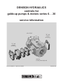
1
DENISON HYDRAULICS
controls for
goldcup pumps & motors series 6. . .30
service information
valve block
"B" side
control
mounting
"A" side
control
mounting
rotation
viewed from shaft end
Publ. S1-AM030-A replaces S1-AM030
Revised 4/02
2
GOLDCUP CONTROLS CONTENTS
DESCRIPTION
PAGE
Ordering Code
Pump Controls____________________________________________________________________________4
Motor Controls____________________________________________________________________________4
Table 1
Typical Characteristics______________________________________________________________________5
Code 1
Screw Adjustment Control. Disassy/Assy/Test___________________________________________________7
Figure 1 Screw Adjustment Control ___________________________________________________________9
Code 2A
Cylinder Control, Disassy/Assy/Test ___________________________________________________________10
Figure 2A Cylinder Control__________________________________________________________________13
Code 2H
3 Position Cylinder Control. Disassy/Assy/Test __________________________________________________14
Figure 2H 3 Position Cylinder Control _________________________________________________________17
Code 40/4A
Rotary Servo, Spring Ctd/Trimmer. Disassy/Assy/Test ____________________________________________18
Figure 4A Rotary Servo, Spring Ctd/Trimmer ____________________________________________________21
Code 4B/4C
Rotary Servo, Brake and Bypass Valve. Disassy/Assy/Test_________________________________________22
Figure 4C Rotary Servo, Brake and Bypass Valve _______________________________________________26
Code 5A
Electric Stroker. Disassy/Assy/Test ___________________________________________________________27
Figure 5A Electric Stroker __________________________________________________________________31
Figure 5A-1 Servo for Electric Stroker (Pump) __________________________________________________33
Figure 5A-2 Servo for Electric Stroker (Motor) __________________________________________________35
Code 5C
Electric Stroker with Brake & Bypass Valve. Disassy/Assy/Test- _____________________________________36
Figure 5C Electric Stroker with Brake & Bypass Valve ____________________________________________41
Figure 5C-1 Brake and Bypass Valve for 5C Control- _____________________________________________43
Code 60
Hydraulic Stroker. Disassy/Assy/Test __________________________________________________________44
Figure 60 Hydraulic Stroker _________________________________________________________________47
Figure 60-1 Servo for Hydraulic Stroker _______________________________________________________48
Code 6A
Hydraulic Stroker/Adj. Stops. Disassy/Assy/Test- ________________________________________________49
Figure 6A Hydraulic Stroker/Adj. Stops- _______________________________________________________53
Code 6B
Hydraulic Stroker with Brake & Bypass Valve. Disassy;/Assy/Test ___________________________________54
Figure 6B Hydraulic Stroker with Brake & Bypass Valve- __________________________________________57
Figure 6B-1 Brake and Bypass Valve for 600 Series-_____________________________________________60
Code 6C
Hydraulic Stroker with Brake & Bypass Valve/Adj. Stops Disassy/Assy/Test ___________________________61
Figure 6C Hydraulic Stroker with Brake & Bypass Valve/Adj. Stops __________________________________64
Code 7*
Feedback for 700 Series HI-IQ Servovalve Control _______________________________________________66
SK-15045 Anti-Backlash Spring Installation for Feedback Controls __________________________________68
Figure 7 Feedback for 700 Series HI-IQ Servovalve Control________________________________________70
Code 8A
Hydraulic Stroker. Disassy/Assy/Test __________________________________________________________71
Figure 8A Hydraulic Stroker Control- __________________________________________________________76
Figure 8A-1 Hydraulic/Electric Stroker Spool Assemblies- _________________________________________77
Code 8C
Hydraulic Stroker with Brake & Bypass Valve. Disassy/Assy/Test ____________________________________78
Figure 8C Hydraulic Stroker with Brake & Bypass Valve- __________________________________________84
Figure 8C-1 Spool Assemblies for 8C & 9C Stroker w/Brake & Bypass Valve-__________________________85
Figure 8C-2 Brake Trimmer for 8C & 9C Stroker w/Brake & Bypass Valve- ____________________________86
Code 9A
Electric Stroker Control Disassy/Assy/Test _____________________________________________________87
Figure 9A Electric Stroker __________________________________________________________________93
Code 9C
Electric Stroker with Brake & Bypass Valve. Disassy/Assy/Test- _____________________________________94
Figure 9C Electric Stroker with Brake & Bypass Valve-____________________________________________100
Code **4
Torque Limiter Option Disassy/Assy/Test_______________________________________________________101
S23-12298 Torque Limiter, One Side of Center,CW-B, CCW-A______________________________________105
S23-12299 Torque Limiter, Both Sides of Center_________________________________________________106
S23-12300 Torque Limiter, One Side of Center, CW-A, CCW-B _____________________________________107
Stroke Indicator Stroke Indicator Disassy/Assy________________________________________________________________108
S13-42064 Stroke Indicator _________________________________________________________________109
Seal Kits
_______________________________________________________________________________________110
Conversions & Formulas __________________________________________________________________________________111
Note: Metric terms are noted in parentheses with decimal point designated by a period, as (2.25 Nm) equals 2,25 Newton meters.
T-1
O-Ring installation tool
3
GOLDCUP CONTROLS ORDERING CODE
P 6 P -2 R 1 C -4 A 2 -A -00 -B 1 -M-XXXXX
Pump series
Control Feature
500 Control
00-with deadband
01-without deadband
Primary Controls
1-Screw Adjustment
2-Cylinder Control
4-Rotary Servo (spring centered w/trimmer)
5-Electrohydraulic Stroker
6-Hydraulic Stroker
7-Servovalve & Feedback Device
8-Proportional Hydraulic Stroker
9-Electrohydraulic Stroker
(All include rotary servo, pressure compensator
override & displ. indicator)
600 Control
00-75-350 PSI (5-24 bar)
01-75-435 PSI (5-30 bar)
02-100-380 PSI (7-26 bar)
03-150-400 PSI (10.3-27.6 bar)
700 Control
00-w/o manual override shut-off
01-w/manual override shut-off
Primary Control Options
0-None
A-Adjustable maximum volume stops
B-Automatic brake control
C-A & B above, together
D-10 GPM Servovalve w/feedback potentiometer
E-10 GPM Servovalve w/feedback RVDT
F-10 GPM Servovalve w/pot. & manual override
w/4A2 Control
G-10 GPM Servovalve w/RVDT & manual override
w/4A2 Control
H-3 pos (Spring centered w/trimmer)
800 Control
00-75-350 PSI (5-24 bar)
01-75-435 PSI (5-30 bar)
02-100-380 PSI (7-26 bar)
03-150-400 PSI (10.3-27.6 bar)
04-75-250 PSI (5-17 bar)
900 Control
00-24 VDC
01-12 VDC
ALL OTHER CONTROLS USE 00
Secondary Controls
2-Auxiliary Replenishment Port on Centerline
4-Torque Limiter and Auxiliary Replenishment Port
Allowable Controls, P_P:
102,104,2A2,2A4,2H2,2H4,402,404,4A2,4A4,4B2,4B4,
4C2,4C4,5A2,5A4,5C2,5C4,602,604,6B2,6B4,7D2,
7E2,7F2,7G2,8A2,8A4,8C2,8C4,9A2,9A4,9C2,9C4,
Control Location
A-Command on Port A side
B-Command on Port B side
(Displ. indicator on opposite side)
Allowable Controls, P_V:*
102,104,2A2,2A4,4A2,4A4,4C2,4C4,5A2,5A4,
5C2,5C4,6A2,6A4,6C2,6C4,7D2,7E2,7F2,7G2,
8A2,8A4,8C2,8C4,9A2,9A4,9C2,9C4
*P_V not available on 24 & 30 Series
M 6 H -2 N 1 C -2 A 0 -A -00 -M-XXXXX
Motor series
Control Feature
500 Control
1-without deadband
Primary Controls
2-Cylinder with adjustable maximum & minimum stops
5-Electrohydraulic Stroker
6-Hydraulic Stroker
8-Proportional Hydraulic Stroker
9-Electrohydraulic Stroker (without deadband)
(All include rotary servo stem and displacement indicator)
600 Control
0-170-350 PSI (11.7-24.1 bar)
1-200-450 PSI (17.2-31 bar)
2-150-380 PSI (10.3-26.2 bar)
3-75-250 PSI (5-17 bar)
Primary Control Options
0-None
A-Adjustable maximum volume stops
800 Control
0-75-250 PSI (5-17 bar)
1-250-450 PSI (17-31 bar)
Secondary Control options
0-None
5-Reverse compensator (not available on 24 & 30 series)
900 Control
0-24 VDC
0-12 VDC
Control Location
A-Command on Port A side
B-Command on Port B side
Allowable Controls: M*V,M*H: 2A0,2A5,5A0,5A5,6A0,6A5,8A0,8A5,9A0,9A5
4
GOLDCUP CONTROLS CHARACTERISTICS
TABLE 1 TYPICAL CHARACTERISTICS
Specifications
Control stop adjustment, 0 to full volume
Typ. Value
1A, 2A, 4A, 4C
6.72 Turns
5A, 5C
8.48 Turns
6A, 6C
6.06 Turns
8A, 8C, 9A, 9C
5.04 Turns
Servo response time, 0 to full volume
P6, P7, P8
.9 Seconds
P11, P14
1.5 Seconds
P24, P30
1.8 Seconds
Compensator off stroke response, full to 0 volume.
P6, P7, P8
.050 Seconds
P11, P14
.070 Seconds
P24, P30
.100 Seconds
Servo shaft rotation, 0 to full volume
19 degrees
Fluid connections:
1/8 Dryseal NPTF
Signal ports, 2A
Signal ports, 2H, 60, 6A, 6B, 6C, 8A, 8C
SAE -4 St. Thd. O-ring seal
Brake port, 4B, 4C, 5C, 6B, 6C, 8C, 9C
SAE -6 St. Thd. O-ring seal
Bypass port to system pressure, 4B, 4C, 5C, 6B, 6C
SAE -4 St. Thd. O-ring seal
Bypass port to system pressure, 8C, 9C
SAE -6 St. Thd. O-ring seal
Bypass port to replenishing, 4B, 4C, 5C, 6B, 6C, 8C, 9C
SAE -6 St. Thd. O-ring seal
*5A, 5C CONTROLS
Specifications
Hysteresis
Typ. Value
Less than 5%
Linearity
Within 5%
Response
0.5 seconds, zero to full. (control response)
Temperature null shift
Less than 2% per 100° F (38°C)
Deadband
0% or 10%
Input pressure
400 psi (28 bar) nominal, range 200-1000 psi (14-70 bar)
Coil resistance
24 to 30 Ohms
Electrical input
Full stroke .275 ma. typ., 400 ma. max., Max. current 600 ma.
Torque for manual operation
20 in.-lb (2.25 Nm) with control pressure shut off.
*Note: If the driver uses Pulse Width Modulation, (PWM) the frequency must be 2000 Hz. or higher to avoid erratic operation.
Water Glycol, Phosphate Ester (including Skydrol), and Invert emulsions cannot be used with 5A and 5C controls.
60, 6A, 6B, 6C PUMP CONTROLS
Feature
Control press.
min. displacement
psi
(bar)
Control press.
max. displacement
psi
(bar)
Max. hysteresis @
min. displacement
psi
(bar)
Max. hysteresis @
max. displacement
psi
(bar)
00
60-90
(4.1-6.2)
310-360
(21.3-24.8)
30
(2.1)
50
(3.4)
01
60-90
(4.1-6.2)
410-460
(28.3-31.7)
30
(2.1)
50
(3.4)
02
100-120
(6.9-8.3)
350-400
(24.1-27.6)
30
(2.1)
50
(3.4)
03
135-165
(9.3-11.4)
375-425
(25.9-29.3)
30
(2.1)
50
(3.4)
5
GOLDCUP CONTROLS CHARACTERISTICS
6A MOTOR CONTROLS
Feature
Control press.
max. displacement
Control press.
min. displacement
Max. hysteresis @
max. displacement
Max. hysteresis @
min. displacement
psi
(bar)
psi
(bar)
psi
(bar)
psi
(bar)
0-
155-185
(10.7-12.7)
310-360
(21.3-24.8)
30
(2.1)
50
(3.4)
1-
185-215
(12.8-14.8)
410-460
(28.3-31.7)
30
(2.1)
50
(3.4)
2-
135-165
(9.3-11.3)
350-400
(24.1-27.6)
30
(2.1)
50
(3.4)
3-
60-90
(4.1-6.2)
225-275
(15.5-19.0)
30
(2.1)
50
(3.4)
700 FEEDBACK CONTROLS
Specifications
Input voltage
Input Amperes
Potentiometer
D.C. RVDT
* Output Volts @ max displacement, 19° CW rotation facing control
Potentiometer
D.C. RVDT
Output impedance
Potentiometer
D.C. RVDT
Typ. Value
+/- 15 Volts
3 ma
30 ma
+3.1 Volts
-2.3 Volts
2.5 K Ohms
<1 Ohm
*With connector terminal B at +15 Volts, terminal D at - 15 Volts. This polarity must be maintained for D.C. RVDT, Polarity is optional
for potentiometer.
8A, 8C PUMP CONTROL
Control press.
Control press
Max. hysteresis @
min. displacement
max. displacement
min. displacement
psi
(bar)
psi
(bar)
psi
(bar)
00
60-90
(4.1-6.2)
310-360
(21.3-24.8)
30
(2.1)
01
60-90
(4.1-6.2)
410-460
(28.3-31.7)
30
(2.1)
02
100-120
(6.9-8.3)
350-400
(24.1-27.6)
30
(2.1)
03
135-165
(9.3-11.4)
375-425
(25.9-29.3)
30
(2.1)
04
60-90
(4.1-6.2)
225-275
(15.5-19.0)
30
(2.1)
Torque for manual operation (no control pressure) begin stroke
7.5-20 in. lb.
Torque for manual operation (no control pressure) end stroke
28-58 in. lb.
Code
Max. hysteresis @
max. displacement
psi
(bar)
50
(3.4)
50
(3.4)
50
(3.4)
50
(3.4)
50
(3.4)
(0.8-2.2 N·m)
(3.2-6.5 N·m)
8A MOTOR CONTROL
Code
Control press.
Control press
min. displacement
max. displacement
psi
(bar)
psi
(bar)
0*
60-90
(4.1-6.2)
225-275
(15.5-19.0)
1*
235-265
(16.2-18.3)
410-460
(28.3-31.7)
Signal ports
Torque for manual operation (no control pressure) begin stroke
Torque for manual operation (no control pressure) end stroke
9A, 9C PUMP CONTROL
Code
mA @min.
mA @max.
displacement
displacement
00
360 +/- 60
650 +/- 110
01
180 +/- 30
325 +/- 55
* Hysteresis- percent of full displacement
* Linearity - percent of full displacement
Manual override
Torque to override (no signal current)
Mating connector (supplied)
Max. hysteresis @
min. displacement
psi
(bar)
30
(2.1)
30
(2.1)
SAE - 4
7.5-20 in. lb.
28-58 in. lb.
Max. hysteresis @
max. displacement
psi
(bar)
50
(3.4)
50
(3.4)
(0.8-2.2 N·m)
(3.2-6.5 N·m)
9A MOTOR CONTROL
Code
0*
1*
mA @max.
displacement
360 +/- 60
180 +/- 30
mA @min.
Coil
displacement
voltage
580 +/- 100
12 Volt
290 +/- 50
24 Volt
5% typ. 8% max.
within 8%
Nom.
resist.
10 Ohm
41 Ohm
3/16"(4.8 mm) internal hex
30 in.-lb (3.4 N•m) typ.
DIN 43650 type AF
*Specifications above are based on using a Jupiter 900 Driver with a 24 VDC supply and set at 120 Hz pulse width modulation.
Performance will vary when other controls are used. 100 to 200 Hz pulse width modulation is recommended.
6
GOLDCUP CONTROLS SERIES 100
CODE 1 - SCREW
ADJUSTMENT CONTROL
S23-12327
“A” Mounting CCW Rotation
“B” Mounting CW Rotation
S23-12328
“A” Mounting CW Rotation
“B” Mounting CCW Rotation
DESCRIPTION
The screw adjustment spring offsets the rotary servo to the maximum displacement as
adjusted by the screw. The operator needs only to override the spring offset torque of
approximately 20 lbs-in. (2.26 Nm) with the rotary servo stem to manually reduce displacement. The minimum displacement is set by the adjustable screw which determines the minimum rotary servo command. The pressure compensator override is
independent of this control. A pump with this control acts as with a traditional pressure
compensator. In the absence of an overriding rotary servo command the pump is held
at the adjustable maximum displacement. The maximum screw is adjustable from
approximately 100% to 0%. The minimum screw is nominally set at zero stroke but is
adjustable from -50% to + 100% displacement.
DISASSEMBLY
See Figure 1
1. Remove screws (2). Remove control from pump. Examine servo plate for excessive scratching. Note if orifices in stem are open. If servo plate is scratched or orifices
appear to be plugged, remove plate and servo stem by removing two socket set
screws from plate, then alternately loosening the two button head screws under the set
screws.
2. Remove retaining ring (4) and press the shaft assembly through the valve body.
3. Examine shoes (8) and (25) for contamination in balance pads or excessive
scratching on faces. Note: the two shoes are not identical and must be installed in the
proper position on reassembly.
4. Remove the plug (17) with attached parts. Remove the spools (15) and spring
(20). Examine spools and bores for free motion, wear or contamination
REWORK OF WEAR PARTS
Description
Servo plate face
Shear seal
Control cover
Spool
PREPARATION FOR ASSEMBLY
Rework
Fine stone to remove raised burrs & dings
Fine stone to remove raised burrs & dings. Note:
grooves to supply balance pads must be present
and adequate.
Stone or lap inside face to remove raised burrs &
dings.
Break sharp edges or dings.
All parts are to be inspected and be free of material defects, dirt, scratches or any foreign material. All parts are to be cleaned with a suitable cleaning solvent and all cores
and passages blown out with clean dry compressed air. After cleaning and inspection,
all parts are to be covered with a light film of oil and should be protected from dirt and
excessive handling until assembled onto the unit. During assembly, lapped and ground
surfaces should be kept lubricated and protected from nicks or surface damage.
1. Apply pipe sealant and install plug (12) in body. Torque to 100 lbs-in. (11.3 Nm)
2. Press spring pins (23) into body, being careful not to mar the surface in the area of
the shoe path.
3. Install O-ring (7) in groove of shear seal (8). Install shear seal with O-ring in the
large hole on the servo link, on the servo shaft side. Be certain that the shear seal is
sitting with the flange flush against the servo link surface.
ASSEMBLY
Note: The shear seal will fit in one position only. Otherwise one side will be held up
by the lip of the servo link. Shear seal (8) must be installed to face against the cover
plate (10). This shear seal differs from shear seal (25) in that the face surface is
machined with two .094” (2.4 mm) radius scallops.
4. Install thrust washers (9) over servo shaft and seat against the servo link.
5. Install O-ring (5) in the second groove from the end of the shaft, using assembly
tool T-1.
6. Install the servo shaft assembly in the cover plate. (11).
7. Install retaining ring (4) into the groove of the servo shaft extending through the
cover plate.
8. Install spools (15) into the bores in the body. Note: Reduced down diameters must
7
GOLDCUP CONTROLS SERIES 100
be to the outside, and spools must freely slip into the bores.
9. Install spring (20) over the spool extension on one side only. See chart for location
relative to the 1/8” pipe plug.
10. Install plugs (17) with O-rings (16). Install remaining parts in plugs.
Pump Shaft
Rotation
clockwise
clockwise
c/clockwise
c/clockwise
Control
mounting
A
B
A
B
Spring loc.
to 1/8” plug
same
opposite
opposite
same
11. Place two spring washers (24), nested with the bent sections matching each other,
into the large hole in the servo link,
12. Place washer (19) against the spring washers.
13. Install O-ring into groove in the remaining shear seal (25). Note: This shear seal
does not contain the two .094” (2.4 mm) radius scallops in the face. Place on top of
washer (32). Position shear seal to match the lip on the servo link.
14. Install control on pump and torque bolts to 30 lbs-ft. (40.8 Nm).
PARTS LIST
For Figure 1 - Screw adjustment
control
S23-12327
CCW - “A” Mtg., CW - “B” Mtg.
S23-12328
CW - “A” Mtg., CCW - “B” Mtg.
8
ITEM
1
DESCRIPTION
Servo shaft assy.
PART NO.
S13-48438
QTY.
1
2
Screw, hwhd. 3/8-16 x 1-1/4
353-25018
4
3
NOT USED
4
Ring, WT 5100-50
356-65070
1
5
O-ring, 70 S-1 ARP 013
671-00013
1
6
Washer, Nyltite #37-3/8”
631-45007
4
7
O-ring, 70 S-1 ARP 017
671-00017
2
8
Shear seal
033-71371
1
9
Thrust washer
350-10103
3
10
NOT USED
11
Control cover
033-54647
1
12
Hex flush plug, 1/8” pipe
431-90204
1
13
O-ring, 90 S-1 ARP 905
691-00905
3
14
Plug, 5P5N-S
488-35028
1
15
Spool
033-72180
2
16
O-ring, 90 S-1 ARP 906
691-00906
2
17
Plug
033-91889
2
18
Nut, cover
033-91890
2
19
Thrust washer
350-10064
1
20
Spring
033-72198
1
21
Soc. setscrew, 10-32 x 1
311-50002
2
22
Nut
333-67000
2
23
Spring pin
325-12120
2
24
Finger spring
350-10067
2
25
Shear seal
033-70525
1
26
Control cover gasket
033-91058
1
9
GOLDCUP CONTROLS SERIES 100
FIGURE 1
SCREW ADJUSTMENT 1-SIDE OF CENTER,
SPRING OFF SET TO FULL W/ADJ. MAX./MIN.
VOLUME STOPS, CCW-B & CW-A
S23-12328
GOLDCUP CONTROLS SERIES 200
CODE 2A CYLINDER CONTROL
S23-12338
”A” Mounting CCW Rotation pump
“B” Mounting CW Rotation pump
S23-12340
”A” Mounting CW Rotation pump
“B” Mounting CCW Rotation pump
S23-12326
”B” Mounting motor
S23-12329
”A” Mounting motor
DESCRIPTION
These controls provide the capability of hydraulically selecting pre-set displacements.
On pump controls, the control is spring biased toward zero displacement. Maximum
and minimum displacements are adjustable from zero to full. On motor controls, the
control is spring offset toward full displacement. Maximum and minimum displacements are adjustable from 1/3 stroke to full. Stroking pistons engage a pin on the
servo arm. When signal pressure is applied to the piston opposite to the spring, the
piston moves, causing the control arm to move to the other position. With a lever
attached to the input shaft, displacement may be manually controlled between these
two limits when there is no control signal
DISASSEMBLY
See Figure 2A
1. Remove screws (2). Remove control from pump. Examine servo plate for excessive scratching. Note if orifices in stem are open. If servo plate is scratched or orifices
appear to be plugged, remove plate and servo stem by removing two socket set
screws from plate, then alternately loosening the two button head screws under the set
screws.
2. Remove retaining ring (4) and press the shaft assembly through the valve body.
3. Examine shoes (8) and (25) for contamination in balance pads or excessive
scratching on faces. Note: the two shoes are not identical and must be installed in the
proper position on reassembly.
4. Remove the plug (18) with attached parts. Remove the spools (15) and/or (22),
and spring (16). Observe spools and bores for free motion, wear or contamination
PREPARATION FOR ASSEMBLY
All parts are to be inspected and free of material defects, dirt, scratches or any foreign
material. All parts are to be cleaned with a suitable cleaning solvent and all cores and
passages blown out with clean dry compressed air.
After cleaning and inspection, all parts are to be covered with a light film of oil and
should be protected from dirt and excessive handling until assembled onto the unit.
During assembly, lapped and ground surfaces should be kept lubricated and protected
from nicks or surface damage.
REWORK OF WEAR PARTS
Description
Servo plate face
Shear seal
Control cover
Spool
ASSEMBLY
Rework
Fine stone to remove raised burrs & dings
Fine stone to remove raised burrs & dings. Note:
grooves to supply balance pads must be present
and adequate.
Stone or lap inside face to remove raised burrs &
dings.
Break sharp edges or dings.
1. Apply pipe sealant and Install plug (12) in body. Torque to 100 lbs-in. (11.3 Nm)
2. Press spring pins (23) into body, being careful not to mar the surface in the area of
the shoe path.
3. Install O-ring in groove of shear seal (8). Install shear seal with O-ring in the large
hole on the servo link, on the servo shaft side. Be certain that the shear seal is sitting
with the flange flush against the servo link surface.
Note: The shear seal will fit in one position only. Otherwise one side will be held up
by the lip of the servo link. Shear seal (8) must be installed to face against the cover
plate (10). This shear seal differs from shear seal (25) in that the face surface is machined with two .094” (2.4 mm) radius scallops.
4. Install needle bearing (9) over servo shaft and seat against the servo link. Install
10
GOLDCUP CONTROLS SERIES 200
thrust washer (6) over needle bearing.
5. Install O-ring (5) in the second groove from the end of the shaft., using installation
tool T-1
6. Install the servo shaft assembly in the control cover (10).
Note: The dowel pin in the arm must be positioned in the rectangular slot beside the
shaft hole. This will position the shear seal (8) face against the cover.
7. Install retaining ring (4) into the groove of the servo shaft extending through the
control cover.
8. Install spools (15) and/or (22) into the bores in the body. Note: reduced down diameters must be to the outside, and spools must freely slip into the bores. Pump controls
use two short spools (22). Motor controls use one long spool, (15) on the side with the
spring, and one short spool (22), on the opposite side. See chart for spring location
relative to item (12) figure 2A.
Pump Shaft
Control
Spring loc.
Rotation
mounting
to 1/8” plug (12)
clockwise
A
same
clockwise
B
opposite
c/clockwise
A
opposite
c/clockwise
B
same
Motor control mtg.
Long spool and Spg.
loc. to 1/8” plug (12)
same
opposite
A
B
9. Install spring (16) over the spool extension on indicated side.
10. Install plugs (17) with O-rings (16). Install remaining parts in plugs.
11. Place two spring washers (24), nested with the bent sections matching each other,
into the large hole in the servo link.
12. Place washer (11) against the spring washers.
13. Install O-ring into groove in the remaining shear seal (25). Note: This shear seal
does not contain the two .094” (2.4 mm) radius scallops in the face. Place on top of
washer (32). Position shear seal to match the lip on the servo link.
14. Install control on pump control pad, over dowels, with gasket, (26). Place new
Nyltite washers (3) on screws (2). Torque to 30 lbs-ft. (40.8 Nm).
TEST
1. Connect lever to input shaft. With unit running, manually stroke the shaft. Do not
exceed 100 lbs-in. (11.3 Nm) torque. Pump or motor cam shall follow the motion of the
input shaft.
Input shaft and cam shall return to the spring biased position when the lever is
released.
2. Set the maximum stop screw for full displacement. Set the minimum stop position.
For motor controls, minimum stroke shall be no less than 25% and no more than 33%
of full stroke, with the lever at minimum stroke and the minimum stop screw backed
away from contact with the piston. Caution! do not allow motor to exceed rated RPM.
For pump controls, set the minimum stop screw for zero displacement. Lock in position.
3. Apply 300 to 600 psi servo supply to signal port. Control shaft shall rotate and
pump or motor shall follow stroke of input shaft.
Pump shaft
rotation
Control
mounting
Signal
port
Tank
port
clockwise
A
Y
X
clockwise
B
X
Y
c/clockwise
A
X
Y
c/clockwise
B
Y
X
Motor control
mounting
A
B
Signal port
X
Y
Tank port
Y
X
“Y” port is adjacent to 1/8” plug (12)
4. Drop signal pressure to minimum. Control shall return to the spring offset position,
and pump or motor shall return to the initial displacement.
11
GOLDCUP CONTROLS SERIES 200
PARTS LIST
For Figure 2A - Cylinder control
12
ITEM
DESCRIPTION
PART NO.
S13-48438
QTY.
PUMP
1
QTY.
MTR.
1
1
Servo shaft assy.
2
3
Screw, hwhd. 3/8-16 x 1-1/4
353-25018
4
4
Washer Nyltite #37
631-45007
4
4
4
Ring, WT 5100-50
356-65070
1
1
5
O-ring, 70 S-1 ARP 013
671-00013
1
1
6
Washer, hardened
350-10141
1
1
7
O-ring, 70 S-1 ARP 017
671-00017
2
2
8
Shear seal
033-71371
1
1
9
Needle bearing
230-82141
1
1
10
Control cover
033-91154
1
1
11
Thrust washer
350-10064
1
1
12
Hex flush plug 1/8” pipe
431-90204
1
1
13
Nut
333-67000
2
2
14
NOT USED
15
Spool, 2.6” (66.0 mm) lg.
033-70844
-
1
16
Spring
033-72181
1
1
17
O-ring, 90 S-1 ARP 906
691-00906
2
2
18
Plug
033-91889
2
2
19
Soc. setscrew.
311-50002
2
2
20
Nut, cover
033-91890
2
2
21
O-ring
691-00905
2
2
22
Spool, 2.26” (57.4 mm) lg.
033-70845
2
1
23
Spring pin
325-12120
2
2
24
Finger spring
350-10067
2
2
25
Shear seal
033-70525
1
1
26
Control cover gasket
033-91058
1
1
13
GOLDCUP CONTROLS SERIES 200
FIGURE 2A
CYLINDER CONTROL
S23-12329
GOLDCUP CONTROLS SERIES 200
CODE 2H 3 POSITION
CYLINDER CONTROL
S23-12358
DESCRIPTION
Code 2H cross center pump controls are spring centered and can be piloted to full
displacement either side of center by introducing a pilot pressure into the control ports.
A trimmer adjustment provides for accurate setting of zero stroke position. Maximum
displacements are adjustable from zero to full stroke.
When there is no control signal, displacement may be manually controlled between
these two limits with a lever attached to the input shaft.
DISASSEMBLY
See Figure 2H
1. Remove screws (17). Remove control from pump. Examine servo plate for excessive scratching. Note if orifices in stem are open. If servo plate is scratched or orifices
appear to be plugged, remove plate and servo stem by removing two socket set
screws from plate, then alternately loosening the two button head screws under the set
screws.
2. Remove retaining ring (4) and press the shaft assembly through the valve body.
3. Examine shoes (8) and (25) for contamination in balance pads or excessive
scratching on faces. Note: the two shoes are not identical and must be installed in the
proper position on reassembly.
4. Remove the plug (29) with attached parts. Remove the spools (27).
5. Remove plugs (22). Remove springs (20) and spools (18). Examine spools and
bores for free motion, wear or contamination.
6. If trimmer adjustment must be removed, carefully tap the spring pin (14) in till flush
with O.D. of screw (13). Remove nut (15), and screw (14). Remove spring pin from
screw.
PREPARATION FOR ASSEMBLY
All parts are to be inspected and be free of material defects, dirt, scratches or any foreign material.
All parts are to be cleaned with a suitable cleaning solvent and all cores and passages
blown out with clean dry compressed air.
After cleaning and inspection, all parts are to be covered with a light film of oil and
should be protected from dirt and excessive handling until assembled onto the unit.
During assembly, lapped and ground surfaces should be kept lubricated and protected
from nicks or surface damage.
REWORK OF WEAR PARTS
Description
Servo plate face
Shear seal
Control cover
Spool
ASSEMBLY
Rework
Fine stone to remove raised burrs & dings
Fine stone to remove raised burrs & dings. Note:
grooves to supply balance pads must be present
and adequate.
Stone or lap inside face to remove raised burrs &
dings.
Break sharp edges or dings.
1. Apply pipe sealant and Install plug (10) in body. Torque to 100 lbs-in. (11.3 Nm)
2. Press rollpins (23) into body, being careful not to mar the surface in the area of the
shoe path.
3. Press pin (12) into screw (13) to 0.38” (9.65 mm) extended length.
4. Install screw (13) into body Pin (12) should extend into spool bore approximately
.090” (2.29 mm). The eccentric pin must be indexed so that it is offset towards the outside surface of the cover plate. The drilled hole for the spring pin (14) should be
approximately centered in the slotted opening in the cover plate. Install spring pin (14)
into trimmer assembly. Leave approximately one-half length of pin extending from
screw. This will allow approximately plus or minus 45° rotation of the trimmer assembly. Install nut (15), O-ring (16), plug (32) and O-ring (31).
5. Install O-ring in groove of shear seal (8). Install shear seal with O-ring in the large
hole on the servo link, on the servo shaft side. Be certain that the shear seal is sitting
with the flange flush against the servo link surface.
Note: The shear seal will fit in one position only. Otherwise one side will be held up
by the lip of the servo link. Shear seal (8) must be installed to face against the cover
plate (11). This shear seal differs from shear seal (25) in that the face surface is machined with two .094” (2.4 mm) radius scallops.
6. Install thrust washers (9) over servo shaft and seat against the servo link.
7. Install O-ring (5) in the second groove from the end of the shaft, using installation
tool T-1.
14
GOLDCUP CONTROLS SERIES 200
8. Install the servo shaft assembly in the control cover (11), engaging the pins in the
slots, with the arm centered between the spring pins.
9. Install retaining ring (4) into the groove of the servo shaft extending through the
control cover.
10. Install spools (18) into the bores in the body adjacent to the trimmer screw. Note
that reduced down diameters must be to the outside, and spools must freely slip into
the bores.
11. Install springs (20). Install O-rings (21) over plugs (22) and install plugs.
12. Install spools (27) in the remaining bores. Note that reduced down diameters
must be to the outside, and spools must freely slip into the bores.
13. Install O-rings (21) on plugs (29). Install plugs in body.
14. Install adjusting screws (2), nuts (3) O-rings (30), plugs (34) and O-rings (33) into
plugs (29).
15. Place two spring washers (24), nested with the bent sections matching each other,
into the large hole in the servo link,
16. Place washer (11) against the spring washers.
17. Install O-ring into groove in the remaining shear seal (25). Note: This shear seal
does not contain the two .094” (2.4 mm) radius scallops in the face. Place on top of
washer (32). Position shear seal to match the lip on the servo link.
18. Install control over dowels, with gasket, (26), washers (6) and screws (17). Torque
to 30 lbs-ft. (40.8 Nm).
TEST
1. Connect lever to input shaft. With unit running, manually stroke the shaft. Do not
exceed 100 lbs-in. (11.3 Nm) torque on shaft. Pump shall follow the motion of the
input shaft.
Input shaft and cam shall return to center when the lever is released.
2. Set the maximum stop screws for full displacement.
3. Remove plug from trimmer adjustment. Loosen locknut and adjust center position
with a screwdriver. Lock on zero stroke position. Stroke pump and release handle,
both sides of center. Pump shall return to zero consistently.
4. Apply 300 to 600 psi (20.5 to 41 bar) servo supply to one control port . The remaining control port shall be connected to tank. Control shaft shall rotate and pump shall
follow stroke of input shaft.
5. Drop signal pressure to minimum. Control shall return to center.
6. Repeat procedure with signal applied to the other control port.
15
GOLDCUP CONTROLS SERIES 200
PARTS LIST
For Figure 2H -3 Position cylinder
control
S23-12358
16
ITEM
1
DESCRIPTION
Servo shaft assy.
PART NO.
S23-12022
QTY.
1
2
Soc. setscrew
311-50002
2
3
Nut, cover
033-91890
2
4
Ring, WT 5100-50
356-65070
1
5
O-ring, 70 S-1 ARP 013
671-00013
1
6
Washer, Nyltite #37-3/8”
631-45007
4
7
O-ring, 70 S-1 ARP 017
671-00017
2
8
Shear seal
033-71371
1
9
Thrust washer
350-10103
3
10
Hex flush plug, 1/8” pipe
431-90204
1
11
Control cover
033-57807
1
12
Pin
033-71003
1
13
Screw, center trim
033-91042
1
14
Spring pin 1/8 x 3/8
325-08060
1
15
Nut
033-91041
1
16
O-ring, 70 S-1 ARP 015
671-00015
1
17
Screw, hwhd. 3/8-16 x 1-1/4
353-25018
4
18
Spool
033-72180
2
19
Thrust washer
350-10064
1
20
Spring
033-72181
2
21
O-ring, 90 S-1 ARP 906
691-00906
4
22
Plug
033-70840
2
23
Spring pin, 3/16 x 3/4
325-12120
2
24
Finger spring
350-10067
2
25
Shear seal
033-70525
1
26
Control cover gasket
033-91058
1
27
Spool
033-70845
2
28
Dust plug, 7/16-20
449-00506
2
29
Plug
033-91889
2
30
Nut
333-67000
2
31
O-ring, 90 S-1 ARP 905
691-00905
3
32
Plug, 5HP5N-S
488-35020
1
33
NOT USED
34
NOT USED
17
GOLDCUP CONTROLS SERIES 200
FIGURE 2H
3 POSITION CYLINDER
SPRING CENTERED W/TRIMMER &
ADJ. MAX. VOLUME STOPS
S23-12358
GOLDCUP CONTROLS SERIES 400
CODE 4O*/4A* ROTARY SERVO
SPRING CENTERED WITH
TRIMMER
S23-12344 - 4O (Less stops)
S23-12325 - 4A (With stops)
DESCRIPTION
Code 4O* and 4A* cross center pump controls are spring centered and can be manually stroked to full displacement either side of center with approximately 20 lbs-in. (2.26
Nm) torque. The spring centered position may be adjusted externally to approximately
+/- 5% displacement. In the 4A control, maximum displacements are adjustable from
zero to full stroke.
DISASSEMBLY
See Figure 4A
1. Remove screws (2). Remove control from pump. Examine servo plate for excessive scratching. Note if orifices in stem are open. If servo plate is scratched or orifices
appear to be plugged, remove plate and servo stem by removing two socket set
screws from plate, then alternately loosening the two button head screws under the set
screws.
2. Remove retaining ring (4) and press the shaft assembly through the valve body.
3. Examine shoes (8) and (28) for contamination in balance pads or excessive
scratching on faces. Note: the two shoes are not identical and must be installed in the
proper position on reassembly.
4. Remove plugs (22) with attached parts. Remove springs (20) and spools (18).
Examine spools and bores for free motion, wear or contamination.
5. If trimmer adjustment must be removed, carefully tap the spring pin (14) in till flush
with O.D. of screw (13). Remove nut (15), and screw (14). Remove spring pin from
screw.
PREPARATION FOR ASSEMBLY
All parts are to be inspected and be free of material defects, dirt, scratches or any foreign material.
All parts are to be cleaned with a suitable cleaning solvent and all cores and passages
blown out with clean dry compressed air.
After cleaning and inspection, all parts are to be covered with a light film of oil and
should be protected from dirt and excessive handling until assembled onto the unit.
During assembly, lapped and ground surfaces should be kept lubricated and protected
from nicks or surface damage.
REWORK OF WEAR PARTS
Description
Servo plate face
Shear seal
Control cover
Spool
ASSEMBLY
Rework
Fine stone to remove raised burrs & dings
Fine stone to remove raised burrs & dings. Note:
grooves to supply balance pads must be present
and adequate.
Stone or lap inside face to remove raised burrs &
dings.
Break sharp edges or dings.
1. Apply pipe sealant and install plug (10) in body. Torque to 100 lbs-in. (11.3 Nm)
2. Press spring pins (26) into body, being careful not to mar the surface in the area of
the shoe path.
3. Press pin (12) into screw (13) to 0.38” (9.65 mm) extended length.
4. Install screw (13) into body Pin (12) should extend into spool bore approximately
.090” (2.29 mm). The eccentric pin must be indexed so that it is offset towards the outside surface of the cover plate. The drilled hole for the spring pin (14) should be
approximately centered in the slotted opening in the cover plate. Install spring pin (14)
into trimmer assembly. Leave approximately one-half length of pin extending from
screw. This will allow approximately plus or minus 45° rotation of the trimmer assembly. Install nut (15), O-ring (16), plug (3) and O-ring (17).
5. Install O-ring (7) in groove of shear seal (8). Install shear seal with O-ring in the
large hole on the servo link, on the servo shaft side. Be certain that the shear seal is
sitting with the flange flush against the servo link surface.
Note: The shear seal will fit in one position only. Otherwise one side will be held up
by the lip of the servo link. Shear seal (8) must be installed to face against the cover
plate (11). This shear seal differs from shear seal (28) in that the face surface is machined with two .094” (2.4 mm) radius scallops.
6. Install thrust washers (9) over servo shaft and seat against the servo link.
7. Install O-ring (5) in the second groove from the end of the shaft, using installation
tool T-1.
18
GOLDCUP CONTROLS SERIES 400
8. Install the servo shaft assembly into the control cover (11), engaging the pin in the
slot.
9. Install retaining ring (4) into the groove of the servo shaft extending through the
control cover.
10. Install spools (18) into the bores in the body. Note that reduced down diameters
must be to the outside, and spools must freely slip into the bores.
11. Install springs (20). Install O-rings (21) over plugs (22) and install plugs.
14. For the 4A control, install adjusting screws (23), nuts (24), O-rings (30), plugs (31)
and O-rings (25) into plugs (22).
15. Place two spring washers (27), nested with the bent sections matching each other,
into the large hole in the servo link.
16. Place washer (19) against the spring washers.
17. Install O-ring (7) into groove in the remaining shear seal (28). Note: This shear
seal does not contain the two .094” (2.4 mm) radius scallops in the face. Place on top
of washer (19). Position shear seal to match the lip on the servo link.
18. Install control over dowels, with gasket, (29), washers (6), and screws (2). Torque
to 30 lbs-ft. (40.8 Nm).
TEST
1. Connect lever to input shaft. With unit running, manually stroke the shaft. Do not
exceed 100 lbs-in. (11.3 Nm) torque on shaft. Pump shall follow the motion of the
input shaft.
Input shaft and cam shall return to center when the lever is released.
2. For 4A controls, set maximum stop screws for full displacement.
3. Remove plug from trimmer adjustment. Loosen locknut and adjust center position
with a screwdriver. Lock on zero stroke position. Stroke pump and release handle,
both sides of center. Pump shall return to zero displacement consistently.
19
GOLDCUP CONTROLS SERIES 400
PARTS LIST
For Figure 4A - Rotary servo
spring centered w/trimmer
S23-12344 - 40* Fixed stops
S23-12325 - 4A* Adjustable max.
volume stops
20
ITEM
1
DESCRIPTION
Servo shaft assembly
PART NO.
S13-48438
QTY 4O*
1
2
Screw, 3/8-16 x 1.25
353-25018
3
Plug, 5HP5N-S
488-35020
1
1
4
Ring, WT 5100-50
356-65070
1
1
5
O-ring, 70 S-1 ARP 013
671-00013
1
1
6
Washer Nyltite #37
631-45007
4
4
7
O-ring, 70 S-1 ARP 017
671-00017
2
2
8
Shear seal
033-71371
1
1
9
Washer, Thrust
350-10103
3
3
10
1/8 Pipe plug
431-90204
1
1
11
Cover plate
033-53576
1
1
12
Pin
033-71003
1
1
13
Screw, center trim
033-91042
1
1
14
Spring pin, 1/8 x 3/8
325-08060
1
1
15
Nut, hex
033-91041
1
1
16
O-ring, 70 S-1 ARP 015
671-00015
1
1
17
O-ring, 90 S-1 ARP 905
691-00905
1
3
18
Spool
033-72180
2
2
19
Thrust Washer
350-10064
1
1
20
Spring
033-72181
2
2
21
O-ring, 90 S-1 ARP 906
691-00906
2
2
22
Plug
033-70840
2
-
4
QTY 4A*
1
4
Plug
033-91889
-
2
23
Soc setscrew
311-50002
-
2
24
Nut, cover
033-91890
-
2
25
Nut
333-67000
-
2
26
Spring pin 3/16 x 3/4
325-12120
2
2
27
Finger spring washer
350-10067
2
2
28
Shear seal
033-70525
1
1
29
Gasket
033-91058
1
1
30
NOT USED
31
NOT USED
21
GOLDCUP CONTROLS SERIES 400
FIGURE 4A
ROTARY SERVO
SPRING CENTERED W/TRIMMER &
ADJ. MAX. VOLUME STOPS
S23-12325
GOLDCUP CONTROLS SERIES 400
CODE 4B*/4C* ROTARY SERVO
SPRING CENTERED WITH
TRIMMER, BRAKE AND
BYPASS VALVE
S23-12343
S23-12324
(4B*)
(4C*)
DESCRIPTION
Code 4B* and 4C* cross center pump controls are spring and pressure centered and
can be manually stroked to full displacement either side of center with approximately
20 lbs-in. (2.26 Nm) torque. The centered position may be adjusted externally to
approximately +/- 5% displacement. In the 4C control, maximum stops may be adjusted from full to zero displacement.
In the same body is contained the brake and bypass valve option. A brake spool,
when energized, connects the brake port to servo pressure. When de-energized, a
spring shifts the spool, connecting the brake port to tank. Another port, located on the
end of the brake valve, is closed by the energizing of the brake spool. When de-energized, this port dumps both pump system ports to the replenishing source, thus
bypassing the small flow generated by slight errors on zero position.
The operation is controlled in this manner: A restricted servo flow is applied to shift
the brake spool. This flow is dumped when a slot in the servo plate aligns with a passage connecting to this spool. This occurs when the pump is on zero stroke. Another
restricted flow is applied to a spool adjacent to the brake spool. This flow is also connected to a passage in one centering piston, containing a ball and seat. When the
control is off center, the ball seats, sealing the passage, to apply servo pressure to the
spool. When the control is on center, a pin extending from the other centering piston
pushes the ball off the seat, to dump the flow,
The brake spool is thus de-energized to set the brake when BOTH the pump cam is at
zero stroke and the rotary servo is at zero command. If the pump is on stroke or the
input is on stroke, the brake spool is energized, releasing the brake.
DISASSEMBLY
See Figure 4C
1. Disconnect brake and bypass lines from control. Remove screws (2). Remove control from pump. Examine servo plate for excessive scratching. Note if orifices in stem
are open. If servo plate is scratched or orifices appear to be plugged, remove plate
and servo stem by removing two socket setscrews from plate, then alternately loosening the two button head screws under the set screws.
2. Remove retaining ring (4) and press the shaft assembly through the valve body.
3. Examine shoes (8) and (50) for contamination in balance pads or excessive
scratching on faces. Note: the two shoes are not identical and must be installed in the
proper position on reassembly.
4. Remove plugs (28) with attached parts. Remove springs (27), pistons (26), and
spools (22), with attached parts. Do not disassemble unless parts are damaged.
Examine spools, pistons and bores for free motion, wear or contamination.
5. If trimmer adjustment must be removed, carefully tap the spring pin (17) in till flush
with O.D. of screw (16). Remove nut (18), and screw (16). Remove spring pin (17)
from screw.
6. Remove bypass valve body (39) with fitting (41) piston (42) and spring (37).
Remove plug (35) and spring (34). Remove spools (33) and (36).
7. Remove shoe (48), and spring (47).
8. Blow through passages to check two orifices (11) and orifice (10) in body for contamination. Check passages in body for free flow.
PREPARATION FOR ASSEMBLY
All parts are to be inspected and be free of material defects, dirt, scratches or any foreign material.
All parts are to be cleaned with a suitable cleaning solvent and all cores and passages
blown out with clean dry compressed air.
After cleaning and inspection, all parts are to be covered with a light film of oil and
should be protected from dirt and excessive handling until assembled onto the unit.
During assembly, lapped and ground surfaces should be kept lubricated and protected
from nicks or surface damage.
REWORK OF WEAR PARTS
Description
Servo plate face
Shear seal
Control cover
dings.
Spool
22
Rework
Fine stone to remove raised burrs & dings
Fine stone to remove raised burrs & dings. Note:
grooves to supply balance pads must be present
and adequate.
Stone or lap inside face to remove raised burrs &
Break sharp edges or dings.
GOLDCUP CONTROLS SERIES 400
ASSEMBLY
1. Install Lee Pluget in body using installation tool and gage.
2. Install orifices (10) and (11) in body. Torque to 25 lbs-in. (2.8 Nm). Make sure that
the orifice (11) in the deeper bore extends past the wall of the valve bore and will not
interfere with spool (33) or spool (22) action.
3. Apply pipe sealant and install plugs (14) in body. Torque to 100 lbs-in. (11.3 Nm)
4. Press rollpins (43) into body, being careful not to mar the surface in the area of the
shoe path.
5. Install O-ring (7) in groove of shear seal (8). Install shear seal with O-ring in the
large hole on the servo link, on the servo shaft side. Be certain that the shear seal is
sitting with the flange flush against the servo link surface.
Note: The shear seal will fit in one position only. Otherwise one side will be held up
by the lip of the servo link. Shear seal (8) must be installed to face against the cover
plate (12). This shear seal differs from shear seal (50) in that the face surface is machined with two .094” (2.4 mm) radius scallops.
6. Install needle bearing (9) over servo shaft and seat against the servo link. Install
thrust washer (54) over needle bearing.
7. Install O-ring (5) in the second groove from the end of the shaft, using installation
tool T-1.
8. Install the servo shaft assembly in the control cover (12), engaging the pin in the
slot.
9. Install retaining ring (4) into the groove of the servo shaft extending through the
control cover.
10. Press pin (15) into screw (16) to 0.38” (9.65 mm) extended length.
11. Install screw (16) into body. Pin (15) should extend into spool bore approximately
.090” (2.29 mm). The eccentric pin must be indexed so that it is offset towards the outside surface of the cover plate. The drilled hole for the spring pin (17) should be
approximately centered in the slotted opening in the cover plate. Install spring pin (17)
into trimmer assembly. Leave approximately one-half length of pin extending from
screw. This will allow approximately plus or minus 45° rotation of the trimmer assembly. Install nut (18) with O-ring (19), locking trimmer in position. Install O-ring (52) and
plug (53).
12. Assemble seat insert (20) and threaded insert (21) into spools (22), using loctite
#271 per instructions on bottle. Inserts must be assembled into the spool end nearest
the 1/8” (3.18 mm) cross drilled holes.
13. When assembled spools (22) are installed in cover plate (12), they are held
against the eccentric pin of the trimmer assembly by springs (27). In this position,
adjusting screw (24) must have the ball (23) unseated by .012” (0.305 mm) to cause
brake release at 5% of stroke. A special fixture permits adjustment to this setting per
AP-01925. In the absence of this fixture, drop ball (23) into the spool containing the
seat insert. Hold the ball against the seat by inserting piston (26) into the bore. Hold
the two spools (22) with inserts together and set the adjusting screw (24) to where it
just contacts the ball. Turn the adjusting screw in 8 3/8 turns past this point and lock
with setscrew (25), being careful not to disturb the setting.
14. Retain ball (23) in spool bore by installing spring pin (17). Make sure that the
ends of the spring pin do not extend beyond the O.D. of the spool.
15. Install pistons (26) into the spools (22). Install spool assemblies in the bore containing the trimmer adjustment. The spool containing the ball is to be on the side with
the orifice (11).
16. Install springs (27) over pistons. Install plugs (28) and O-rings (29).
17. Install spools (33) and (36) into the other cross-bore in the cover (12). Spool (33)
should be on the side with the orifice (11), and with the slotted side to the outside.
18. Install spring (34) and plug (35) with O-ring (29) on this side.
19. Install O-rings (40) on fitting (41). Install piston (42) in bore of body (39). Install
fitting (41) on body (39) and install assembly in cover (12).
20. Install O-rings (44) and (45) on vent post (46). Install vent post in cover. Install
spring (47) and shoe (48) on vent post.
21. Place two spring washers (49), nested with the bent sections matching each other,
into the large hole in the servo link.
22. Place washer (55) against the spring washers.
23. Install O-ring (7) into groove in the remaining shear seal (50). Note: This shear
seal does not contain the two .094” (2.4 mm) radius scallops in the face. Place on top
of washer (55). Position shear seal to match the lip on the servo link.
24. For 4C controls, install adjusting screws (2), nuts (3) O-rings (30), plugs (34) and
O-rings (33) into plugs (29).
25. Install control over dowels, with gasket, (51), washers (3) and screws (2). Torque
to 30 lbs-ft. (40.8 Nm).
26. Install bypass tubing lines.
23
GOLDCUP CONTROLS SERIES 400
TEST
Install a needle valve on the bypass valve exhaust port, connected to tank. Close the
valve.
Install a 1000 psi (70 bar) gage in the brake port.
1. Start prime mover and adjust compensator for 1000 psi (345 bar).
2. Turn centering trimmer screw to place input shaft on the zero stroke position.
Stroke pump towards full and release, on both sides of center. Pump shall return to
zero stroke within 200 psi (13.8 bar) max.
3. For 4C controls, unload pump, set maximum volume stops to full displacement.
4. Load pump. Stroke pump CW. The gage on the brake port should start to indicate
servo pressure when the system pressure is between 2000 and 4500 psi (138 and 310
bar), with an increasing signal, and must return to case pressure before system pressure drops to 2000 psi (138 bar), on decreasing signal. Repeat by rotating input shaft
CCW. If pressures are incorrect remove piston assembly containing the adjustment
screw, to change ball gap setting. Extend adjustment to increase pressures, retract to
reduce pressures. Standard setting is .012” (0.305 mm) gap, which is 3/8 turn of
adjustment beyond closed position.
5. When finished adjusting, record both pressures for each rotation of the servo input
shaft.
6. Open the needle valve on the neutral bypass port. Measure and record leakage
from this port with the pump on center at minimum psi, and with the pump off center,
at 5000 psi (345 bar).
Maximum leakage with control on center:
2.0 gpm (7.6 l/m)
Minimum leakage with control on center:
1.0 gpm (3.8 l/m)
Maximum leakage with control off center:
35 cu. in/min or .15 gpm (574 cm3/min. or 0.57 l/m)
7. Unload pump. Stroke pump above and below center. Control should operate
smoothly. Brake pressure should drop to case pressure each time control is on center,
and it should indicate servo pressure as soon as input shaft is rotated CW or CCW
from center, per step 4 above.
8. Release control when pump is off center. Pump should return to center
9. Remove needle valve from bypass exhaust port and install exhaust line.
24
GOLDCUP CONTROLS SERIES 400
PARTS LIST
For Figure 4C - Rotary servo with
brake and bypass valve
S23-12343 - 4B* Fixed stops
S23-12324 - 4C* Adjustable max. stops
ITEM
1
2
3
4
5
6
7
8
9
10
11
12
13
14
15
16
17
18
19
20
21
22
23
24
25
26
27
28
29
30
31
32
33
34
35
36
37
38
39
40
41
42
43
44
45
46
47
48
49
50
51
52
53
54
55
56
25
DESCRIPTION
Servo shaft assembly
Screw, hwhd. 3/8-16 x 1 1/4
Washer, Nyltite #37
Retaining ring, WT 5100-50
O-ring, 70 S-1 ARP 013
Plug 2HP5N-S
O-ring, 70 S-1 ARP 017
Shear seal
Needle bearing
Orifice, .028” (.71 mm), 1/16 PT
Orifice plug
Control cover
Lee Pluget
1/8” Hex flush plug
Pin
Center trim screw
Spring pin 1/8 x 3/8
Hex nut
O-ring, 70 S-1 ARP 015
Seat insert
Threaded insert
Spool
Ball, 3/16”
Adjustment screw
Soc setscrew, 6-32 x 1/4
Piston
Compression spring
Plug
Plug, threaded
O-ring, 90 S-1 ARP 906
Soc setscrew, 10-32 x 1”
Cover nut, #10-32
O-ring, 70 S-1 ARP 010
Spool
Spring
Plug, 6P5ON-S
Spool
Spring
Dowel pin, 1/8 x 1/2
Body
O-ring, 90 S-1 ARP 016
Fitting
Piston
Spring pin, 3/16 x 3/4
O-ring, 90 S-1 ARP 902
O-ring, 70 S-1 ARP 006
Vent post
Compression spring
Shoe
Finger spring washer
Shear seal
Control gasket
O-ring, 90 S-1 ARP 905
Plug, 5HP5N-S
Washer
Thrust washer
Plug, 2P5N-S
PART NO.
S13-48438
353-25018
631-45007
356-65070
671-00013
488-35046
671-00017
033-71371
230-82141
037-19104
033-71437
033-91110
447-00017
431-90204
033-71003
033-91042
325-08060
033-91041
671-00015
033-71001
033-71000
033-70839
201-06001
033-71113
311-06042
033-70835
225-92040
033-70840
033-70841
691-00906
312-35040
033-91040
671-00010
033-70999
033-71112
488-35003
033-70997
033-70992
324-20808
033-91090
691-00016
033-70998
033-70993
325-12120
691-00902
671-00006
033-70995
225-92044
033-70996
350-10067
033-70525
033-91058
691-00905
488-35020
350-10141
350-10064
488-35029
QTY. 4B*
1
4
4
1
1
2
1
1
1
2
1
1
7
1
1
2
1
1
1
1
2
1
1
1
2
2
2
3
2
2
1
1
1
1
1
1
1
2
1
1
2
1
1
1
1
1
2
1
1
1
1
1
1
-
QTY. 4C*
1
4
4
1
1
1
2
1
1
1
2
1
1
7
1
1
2
1
1
1
1
2
1
1
1
2
2
2
3
2
2
2
1
1
1
1
1
1
1
2
1
1
2
3
1
1
1
1
2
1
1
1
1
1
1
1
26
GOLDCUP CONTROLS SERIES 400
FIGURE 4C
ROTARY SERVO
SPRING & PRESSURE CENTERED W/TRIMMER
NEUTRAL BY-PASS & BRAKE, HANGER
& ROTARY INPUT ACT., MAX. VOL. STOPS
GOLDCUP CONTROLS SERIES 500
CODE 5A - ELECTRIC
STROKER
S23-12413 - 5A* 00 (with deadband)
S23-12415 - 5A* 01 (no deadband)
S23-12419 - 5A* - A Mtg., Motor
S23-12418 - 5A* - B Mtg., Motor
This control is used on both pumps and motors. The rotary servo input shaft is actuated by a hydraulic spool. A jet pipe is directed to two receiver orifices connecting to
opposite ends of the hydraulic spool. The jet pipe is mechanically centered by a null
adjust spring opposed by a feedback spring linked to spool position. A “voice coil”
attached to the jet pipe creates an unbalance force in proportion to electrical current
magnitude and direction. This causes the jet pipe to offset, increasing pressure on the
one receiver and lowering pressure on the other receiver. The hydraulic spool responds causing the feedback spring to oppose the force, until the jet pipe is again centered at a new position of the servo.
When servo pressure to the jet pipe is blocked, the rotary servo spring centers and
may be manually positioned.
Motor controls are configured to be offset to full stroke with zero signal, and 1/3 stroke
with full signal. A spring in the rotary servo body biases the control to this position.
Cross center pump controls come in two versions. One version (feature 00) requires a
small signal (deadband) prior to commencing stroke in either direction. The feature 01
control has no deadband.
DESCRIPTION
Note: This control is precision manufactured and requires training to properly
assemble or disassemble. Unless repair parts and factory trained personnel
are available, service should be limited to null adjustment.
NULL ADJUSTMENT:
If control functions over its full range, but pump remains on stroke when there is no
electrical signal, adjustment of null position is indicated.
1. Load pump. Set compensator to 1000 psi (69 bar). Shut off external servo supply
to control.
2. If system contains a shuttle valve, disable the shuttle valve as follows:. If shuttle is
on the pump, turn the shuttle relief adjustment two turns in. If it is a Denison shuttle
mounted on the motor, remove shuttle and plug the two threaded ports with 3/8-24
setscrews. Re-install the valve.
3. Adjust and lock the trimmer for minimum system pressure on both ports. Connect a
handle to the .375” (9.52 mm) dia. shaft extension on the stroker. Stroke the pump
both sides of center. Do not exceed 100 lbs-in. (11.3 Nm) torque. Observe pressures
on system ports when handle is released. Continue adjustment till pressure on either
side is less than 150 psi (10.3 bar) difference.
4. To set jet pipe null adjustment, disconnect electrical signal and open servo oil supply
to stroker. (200 psi min., 1000 psi max.) (14 bar min., 69 bar max.). For pump controls with deadband, rotate the jet pipe null adjustment CCW and CW to develop 700
psi (48 bar) on each system port. Caution: always begin adjustment by backing
out (CCW) on the jet pipe null adjustment and observing control reaction.
Overadjusting clockwise direction can damage the jet pipe or the trimmer
spring. Set and lock the screw midway between these two limits. Torque to 10 lbs-in.
(1.1 Nm) max. Install O-ring and cover nut.
5. For pump controls with no deadband, set and lock the jet pipe null adjustment at
the point of minimum system pressure on both ports with pump at operating temperature.
6. For motor controls, set and lock the jet pipe null adjustment to just before the control commences to destroke.
7. Connect electrical signal and zero the electrical driver “zero adjustment”.
8. Restore shuttle valve and system pressure settings to original operating conditions.
PROCEDURE FOR CLEANING
FILTER
See Figure 5A
A screen in the servo inlet line to the stroker prevents particles from getting into the jet
pipe which might plug the jet pipe. In older models, this screen is behind the plug,
(13). Field service is not recommended, as contaminants are on the outside, and
could become dislodged in the servo body upon removal. In later models the screen is
behind the fitting supplying servo oil to the stroker, and contaminants are lodged
inside. With caution, it is possible to clean this filter as follows:
1. Disconnect servo tube line. Remove control from pump.
2. Remove plug (13).
3. Blow filtered air into the opening under the plug. Note if air escapes from the servo
connection.
4. Force filtered oil or a compatable solvent through the opening to flush contaminants
from the screen and out the servo inlet connection.
27
GOLDCUP CONTROLS SERIES 500
5. Carefully remove the filter without dislodging dirt into the opening. In recent controls, this filter is retained by a drilled hex plug. Backflush as before by forcing filtered
oil into the port behind plug (13). Clean and install filter.
6. Examine surface of control cover for excess scratching. Examine shear seal for
contamination in balance pads or deep scratches. Stone lightly to remove raised burrs
and dings. Check that grooves supplying servo oil to balance pads are open.
See Figure 5A-1 or Figure 5A-2
7. Place two spring washers (1-6), nested with the bent sections matching each other,
into the large hole in the servo link.
8. Place washer (1-10) against the spring washers.
9. Install O-ring (1-8) into groove in the shear seal (1-7). Install shear seal. Place on
top of washer, (1-10). Position shear seal to match the lip on the servo link.
10. If control is to be tested on unit, install on control pad with new gasket and new
Nyltite washers under screws. Torque to 30 lbs- ft. (40.8 Nm). Connect servo line and
electrical connector to stroker.
TEST, PUMP CONTROL
1. With servo pressure applied, bleed air from force motor by loosening the screws
holding the electrical connector to the cap. If force motor faces down, bleed air from
the stroke limiting screws. Command stroker back and forth to assure that all air is
purged from the stroke piston, and stroker is functioning properly.
2. Set compensator to 1000 psi (69 bar). Block pump outlet lines. Shut off external
servo supply to control.
3. If system contains a shuttle valve, disable the shuttle valve as follows:. If shuttle is
on the pump, turn the shuttle relief adjustment two turns in. If system contains a
Denison shuttle mounted on the motor, remove shuttle and plug the two threaded ports
with 3/8-24 setscrews. Re-install the valve.
4. Adjust and lock the mechanical trimmer for minimum system pressure on both ports.
Connect a handle to the .375” (9.52 mm) dia. shaft extension on the stroker. Stroke
the pump both sides of center. Do not exceed 100 lbs-in. (11.3 Nm) torque. Release
handle and observe pressures on system ports. Continue adjustment till pressure is
less than 150 psi (10.3 bar) difference on either side.
5. For controls with deadband, (feature 00). To set jet pipe null adjustment, disconnect electrical signal and supply servo oil to stroker. (200 psi min, 1000 psi max.) (14
bar min., 69 bar max.). Rotate the jet pipe null adjustment CCW and CW to develop
700 psi (48 bar) on each system port. Caution: always begin adjustment by backing out (CCW) on the jet pipe null adjustment and observing control reaction.
Overadjusting clockwise direction can damage the jet pipe or the trimmer
spring. Set the screw midway between these two limits and lock. Torque to 10 lbs-in.
(1.1 Nm) max. Install O-ring and cover nut.
6. Reconnect electrical signal and zero the electrical driver “zero adjustment” for minimum pressure.
7. Stroke to full displacement. Turn in maximum stroke stop till pump just commences
reducing stroke. Lock in this position. Repeat with current of opposite polarity
8. Slowly apply current to the valve. Note the value of current at which pressure starts
to build (e.g. +40MA). Back off current and slowly apply the opposite polarity current to
the valve. Note the value of current at which pressure builds the opposite side of center (e.g. -50MA). The sum of the absolute values must be between 50 and 100 MA
(e.g. 40 + 50=90MA), and the difference between the two absolute values must be less
than 20MA. (e.g. 50 - 40=10MA). If not within specification, readjust jet pipe null.
9. For controls with no deadband, (feature 01), disconnect the electrical connector,
supply servo oil to the control. Set and lock the jet pipe null adjustment at the point of
minimum system pressure on both ports with pump at operating temperature. Torque
to 10 lbs-in. (1.1 Nm) max. Caution: always begin adjustment by backing out
(CCW) on the jet pipe null adjustment and observing control reaction.
Overadjusting clockwise direction can damage the jet pipe or the trimmer
spring. Install O-ring and cover nut.
10. For all controls, apply 330MA to the control. The pump should go to full displacement. With the “A” terminal positive, control shaft should rotate CCW. Repeat for
opposite side.
11. With pump at full displacement, block the servo supply to the stroker, The pump
should spring center within 3 seconds.
12. Check for smooth change in displacement with gradual increase and decrease of
control signal.
13. Restore shuttle valve and system pressure settings to original operating conditions.
TEST, MOTOR CONTROL
28
1. With servo pressure applied, bleed air from stroker force motor by loosening the
screws holding the electrical connector to the cap. If force motor faces down, bleed air
from the stroke limiting screws. Command stroker back and forth to assure that all air
is purged from the stroke piston, and stroker is functioning properly.
2. With motor running at low speed and servo supply shut off, turn in maximum stop
GOLDCUP CONTROLS SERIES 500
screw till motor just commences to reduce stroke (increase speed). Lock in this posi
tion.
3. Open servo supply (200 psi min, 1000 psi max.) (14 bar min. 69 bar max.) and
apply current (330 ma Max.), polarity to cause reduced stroke. Adjust minimum stroke
screw for 1/3 stroke. (speed increased to three times initial speed) Lock in this position.
4. With motor at 1/3 stroke, shut off servo supply. Motor shall return to full stroke in 3
seconds max..
5. To set jet pipe null adjustment, disconnect electrical connector. Open servo supply.
Rotate the jet pipe null adjustment CCW and CW. Set and lock at the point just before
the stroker begins to reduce stroke (increase speed). Torque to 10 lbs-in. (1.1 Nm)
max Caution: always begin adjustment by backing out (CCW) on the jet pipe null
adjustment and observing control reaction. Over-adjusting clockwise direction
can damage the jet pipe or the trimmer spring. Install O-ring and cover nut.
6. Re-connect electrical signal and zero the “zero adjustment”.
7. Apply 330MA to the control. The motor should go to 1/3 displacement. With the “A”
terminal positive, control shaft should rotate CCW, and vice versa.
8. Check for smooth change in displacement with gradual increase and decrease of
control signal.
29
GOLDCUP CONTROLS SERIES 500
Feature ➔
00
Pump
01 A Mtg. B Mtg.
Pump Motor Motor
DESCRIPTION
Rotary servo (Fig. 5A-1)
PART NO.
S23-12346
QTY.
1
QTY.
1
QTY.
-
QTY.
-
Rotary servo (Fig. 5A-2)
S23-12540
-
-
1
-
PARTS LIST
For Figure 5A Electric stroker
PUMP CONTROLS
S23-12413 - 5A* 00 (With Deadband)
S23-12415 - 5A* 01 (No Deadband)
MOTOR CONTROLS
S23-12419 - 5A* A Mtg.
S23-12418 - 5A* B Mtg.
ITEM
1
Rotary servo
S23-12539
-
-
-
1
2
Cover nut 1/4-28
033-91038
2
2
2
2
3
Screw. SHC 1/4-28 x1
312-11160
2
2
1
1
4
O-ring, 70 S-5 ARP 011
675-00011
2
2
2
2
5
Screw, SHC 1/4-20 x 3/4
358-12120
8
8
8
8
6
Body-EH Stroker
033-72117
1
1
1
1
7
Spool
033-53439
1
1
1
1
8
Pluget, Lee
447-00017
2
2
2
2
9
Gasket
033-72109
2
2
2
2
10
Cover plate
033-54538
2
2
2
2
11
Screw, SHC 5/16-18 x 1 1/4
358-14180
2
2
2
2
12
O-ring, 70 S-5 ARP 012
675-00012
2
2
2
2
13
Plug, 4HP5N-S
488-35061
1
1
1
1
14
O-ring, 90 S-5 ARP 904
695-00904
1
1
1
1
15
Plug, 2HP5N-S
488-35046
2
2
2
2
16
Screw, SHC, 10-24 x 5/8
358-10100
1
-
-
-
Screw, SHC, 10-24 x 1/2
358-10080
-
1
1
1
Bearing, 3/8 x 9/16 x 1/2
230-82174
1
-
-
-
17
30
Bearing, 3/8 x 9/16 x 5/8
230-00610
-
1
1
1
18
O-ring, 70 S-5 ARP 110
675-00110
1
1
1
1
19
Clamp
033-53688
1
-
-
-
20
O-ring, 90 S-5 ARP 902
695-00902
2
2
2
2
21
Pin
033-53894
1
1
1
1
22
Link, control
033-53687
1
-
-
-
Clamp
033-72111
-
1
1
1
23
Bushing
033-72112
1
1
1
1
24
O-ring 70 S-5 ARP 017
675-00017
1
1
1
1
25
Dowel pin, 1/8 x 1/2
324-20808
1
-
-
-
26
Dowel pin, 3/16 x 1/2
324-21208
1
1
1
1
27
Tubing, servo control
S23-12939
1
1
1
1
28
Connector, 4-F5BX-S
493-15027
1
1
1
1
29
Screw
033-91103
1
1
1
1
30
Filter element
033-91104
1
1
1
1
31
Screw, SHC 1/4-28 x 1 1/2
312-11200
-
-
1
1
32
Fitting, swivel nut elbow
496-15009
1
1
1
1
33
Force motor
S13-46096
1
1
1
1
34
Nameplate
033-91430
1
1
1
1
35
Screw, HWHD 3/8-16 x 1 1/4
353-25018
4
4
4
4
36
Washer, Nyltite #37
631-45007
4
4
4
4
37
Drive screw,#2 x 3/16
320-10203
4
4
4
4
31
GOLDCUP CONTROLS SERIES 500
FIGURE 5A
ELECTRIC STROKER
MOTOR CONTROL "O" DEAD BAND
"A" MTG. SHOWN
REVERSE ITEMS 3, 31 FOR "B" MTG.
GOLDCUP CONTROLS SERIES 500
PARTS LIST
For Figure 5A-1 - Servo for electric
stroker - pump
ITEM
1
S23-12346
Rotary servo for pump electric stroker
32
DESCRIPTION
Servo shaft, link & shear seal
PART NO.
S23-12497
QTY.
(1)
1-1
Servo shaft
033-54841
1
1-2
Pin
033-71002
1
1-3
Servo link
033-70536
1
1-4
Washer
350-10141
1
1-5
Shear seal, feed
033-71371
1
1-6
Washer, finger spring
350-10067
2
1-7
Shear seal
033-70525
1
1-8
O-ring, 70 S-5 ARP 017
675-00017
2
1-9
Needle bearing
230-82141
1
1-10
Thrust washer
350-10064
1
2
O-ring, 90 S-5 ARP 905
695-00905
1
3
Plug, 5-HP5N-S
488-35020
1
7
Gasket
033-91058
1
9
Cover plate
033-72114
1
12
Plug
033-70840
2
13
O-ring, 90 S-5 ARP 906
695-00906
2
14
Spring
033-72181
2
15
Spool, short
033-72180
2
16
Fitting, male elbow
473-15042
1
17
O-ring, 70 S-5 ARP 015
675-00015
1
18
Screw, center trim
033-91042
1
19
Nut
033-91041
1
20
Spring pin 1/8 x 3/8
325-08060
1
21
Pin
033-71003
1
33
GOLDCUP CONTROLS SERIES 500
FIGURE 5A-1
CONTROL ROTARY SERVO FOR HYD. STROKER
SPRING CENTERED WITH TRIMMER
S23-12346
GOLDCUP CONTROLS SERIES 500
PARTS LIST
For Figure 5A-2 - Servo for electric
stroker- motor
S23-12540 - 5A* A Mtg.
23-12539 - 5A* B Mtg.
Rotary servo for motor electric stroker
34
ITEM
1
DESCRIPTION
Servo shaft, link & shear seal
PART NO.
S23-12497
QTY.
(1)
1-1
Servo shaft
033-54841
1
1-2
Pin
033-71002
1
1-3
Servo link
033-70536
1
1-4
Washer
350-10141
1
1-5
Shear seal, feed
033-71371
1
1-6
Washer, finger spring
350-10067
2
1-7
Shear seal
033-70525
1
1-8
O-ring, 70 S-5 ARP 017
675-00017
2
1-9
Needle bearing
230-82141
1
1-10
Thrust washer
350-10064
1
2
Gasket
033-91058
1
3
Cover plate
033-72114
1
4
Spool, short
033-72180
1
5
Plug
033-70840
2
6
O-ring, 90 S-5 ARP 906
695-00906
2
7
Spring
033-72181
1
8
Spool, long
033-70844
1
9
Fitting, male elbow
473-15042
1
10
Plug, 5-P5N-S
488-35028
1
11
O-ring, 90 S-5 ARP 905
695-00905
1
35
GOLDCUP CONTROLS SERIES 500
FIGURE 5A-2
ASSEMBLY ROTARY SERVO,
SPRING OFF-SET, ELEC/HYD. CONTROL;
A SIDE INPUT, REVERSE ASSEMBLY OF
4, 7, 8 FOR B SIDE INPUT
S23-12540
GOLDCUP CONTROLS SERIES 500
CODE 5C - ELECTRIC
STROKER WITH BRAKE AND
BYPASS
S23-12414 - 5C* 00 (With Deadband)
S23-12420 - 5C* 01 (No Deadband)
DESCRIPTION
This control is used on pumps. The rotary servo input shaft is actuated by a hydraulic
spool. A jet pipe is directed to two receiver orifices connecting to opposite ends of the
hydraulic spool. The jet pipe is mechanically centered by a null adjust spring opposed
by a feedback spring linked to spool position. A “voice coil” attached to the jet pipe
creates an unbalance force in proportion to electrical current magnitude and direction.
This causes the jet pipe to offset, increasing pressure on the one receiver and lowering pressure on the other receiver. The hydraulic spool responds causing the feedback
spring to oppose the force, until the jet pipe is again centered at a new position of the
servo.
When servo pressure to the jet pipe is blocked, the rotary servo spring centers, and
may be manually positioned.
One version of the cross center control requires a small signal (deadband) prior to
commencing stroke in either direction. This control contains spring centering pistons
and neutral trimmer adjustment for accurate centering. Another version, (no deadband)
provides linear displacement with input command for accurate servo applications.
In the control cover is contained the brake and bypass valve option. A brake spool,
when energized, connects the brake port to servo pressure. When de-energized, a
spring shifts the spool, connecting the brake port to tank. Another port, located on the
end of the brake valve, is closed by the energizing of the brake spool. When de-energized, this port dumps both pump system ports to the replenishing source, thus
bypassing the small flow generated by slight errors on zero position.
The operation is controlled in this manner: A restricted servo flow is applied to shift
the brake spool. This flow is dumped when a slot in the servo plate aligns with a passage connecting to this spool. This occurs when the pump is on zero stroke. Another
restricted flow is applied to a spool adjacent to the brake spool. This flow is also connected to a passage in one centering piston, containing a ball and seat. When the
control is off center, the ball seats, sealing the passage, to apply servo pressure to the
spool. When the control is on center, a pin extending from the other centering piston
pushes the ball off the seat, to dump the flow,
The brake spool is thus de-energized to set the brake when BOTH the pump cam is at
zero stroke and the rotary servo is at zero command. If the pump is on stroke or the
input is on stroke, the brake spool is energized, releasing the brake.
DISASSEMBLY
See Figure 5C
Note: This control is precision manufactured and requires training to properly
assemble or disassemble. Unless repair parts and factory trained personnel
are available, service should be limited to the brake and bypass portion, and
null adjustment
NULL ADJUSTMENT:
36
If control functions over its full range, but pump remains on stroke when there is no
electrical signal, adjustment of null position is indicated.
1. Load pump. Set compensator to 1000 psi (69 bar). Shut off external servo supply
to control.
2. If system contains a shuttle valve, disable the shuttle valve as follows:. If shuttle is
on the pump, turn the shuttle relief adjustment two turns in. If it is a Denison shuttle
mounted on the motor, remove shuttle and plug the two threaded ports with 3/8-24
setscrews. Re-install the valve.
3. Adjust and lock the trimmer for minimum system pressure on both ports. Connect a
handle to the .375” (9.52 mm) dia. shaft extension on the stroker. Stroke the pump
both sides of center. Do not exceed 100 lbs-in. (11.3 Nm) torque. Observe pressures
on system ports when handle is released. Continue adjustment till pressure on either
side is less than 150 psi (10.3 bar) difference.
4. To set jet pipe null adjustment, disconnect electrical signal and open servo oil supply
to stroker. (200 psi min, 1000 psi max.) (14 bar min. 69 bar max.). For pump controls
with deadband, rotate the jet pipe null adjustment CCW and CW to develop 700 psi
(48 bar) on each system port. Caution: always begin adjustment by backing out
(CCW) on the jet pipe null adjustment and observing control reaction.
Overadjusting clockwise direction can damage the jet pipe or the trimmer
spring. Set and lock the screw midway between these two limits. Torque to 10 lbs-in.
(1.1 Nm) max. Install O-ring and cover nut.
5. For pump controls with no deadband, set and lock the jet pipe null adjustment at
the point of minimum system pressure on both ports with pump at operating temperature.
GOLDCUP CONTROLS SERIES 500
6. Connect electrical signal and zero the electrical driver “zero adjustment”.
7. Restore shuttle valve and system pressure settings to original operating conditions.
PROCEDURE FOR CLEANING
FILTER
A screen in the servo inlet line to the stroker prevents particles from getting into the jet
pipe which might plug the jet pipe. In older versions, this screen is behind the plug,
(13). Field service is not recommended, as contaminants are on the outside, and
could become dislodged in the servo body upon removal. In later versions the screen
is behind the fitting supplying servo oil to the stroker, and contaminants are lodged
inside. With caution, it is possible to clean this filter as follows:
1. Disconnect servo tube line. Remove control from pump.
2. Remove plug (13).
3. Blow filtered air into the opening under the plug. Observe for air from the servo
connection.
4. Force filtered oil or a compatable solvent through the opening to flush contaminants
from the screen and out the servo inlet connection.
5. Carefully remove the filter without dislodging dirt into the opening. In latest version,
this filter is retained by a drilled hex plug. Backflush as before by forcing filtered oil
into the port behind plug (13). Clean and install filter.
6. Examine surface of control cover for excess scratching. Examine shear seal for
contamination in balance pads or deep scratches. Stone lightly to remove raised burrs
and dings. Check that grooves supplying servo oil to balance pads are open.
7. Place two spring washers (31-6), nested with the bent sections matching each
other, into the large hole in the servo link.
8. Place washer (31-10) against the spring washers.
9. Install O-ring (31-8) into groove in the shear seal (31-7). Install shear seal Place
on top of washer, (31-10). Position shear seal to match the lip on the servo link.
10. If control is to be tested on unit, install on control pad with new gasket and new
Nyltite washers under screws. Torque to 30 lbs- ft. (40.8 Nm). Connect bypass tubing
lines. Connect servo line and electrical connector to stroker.
DISASSEMBLY OF BRAKE AND
BYPASS PORTION
See Figure 5C-1
1. Remove plugs (28). Remove springs (27), pistons (26), and spools (22), with
attached parts. Do not disassemble unless parts are damaged. Examine spools, pistons and bores for free motion, wear or contamination.
2. If trimmer adjustment must be removed, carefully tap the spring pin (17) in till flush
with O.D. of screw (16). Remove nut (18), and screw (16). Remove spring pin (17)
from screw.
3. Remove bypass valve body (36) with fitting (38) piston (39) and spring (34).
Remove plug (32) and spring (31). Remove spools (30) and (33).
4. Remove shoe (45), and spring (44).
5. Blow through passages to check two orifices (11) and orifice (10) in body for contamination. Check passages in body for free flow.
PREPARATION FOR ASSEMBLY
All parts are to be inspected and be free of material defects, dirt, scratches or any foreign material.
All parts are to be cleaned with a suitable cleaning solvent and all cores and passages
blown out with clean dry compressed air.
After cleaning and inspection, all parts are to be covered with a light film of oil and
should be protected from dirt and excessive handling until assembled onto the unit.
During assembly, lapped and ground surfaces should be kept lubricated and protected
from nicks or surface damage.
REWORK OF WEAR PARTS
Description
Servo plate face
Shear seal
Control cover
Spool
Shoe
ASSEMBLY
See Figure 5C-1
37
Rework
Fine stone to remove raised burrs & dings
Fine stone to remove raised burrs & dings. Note:
grooves to supply balance pads must be present
and adequate.
Stone or lap inside face to remove raised burrs &
dings.
Break sharp edges or dings.
Stone to remove raised burrs or dings.
1. Install orifices (10) and (11) in body. Torque to 25 lbs-in. (2.8 Nm). Make sure that
the orifice (11) in the deeper bore extends past the wall of the valve bore and will not
interfere with spool (33) or spool (22) action.
2. Apply pipe sealant and install plugs (14) in body. Torque to 100 lbs-in. (11.3 Nm)
3. Press pin (15) into screw (16) to 0.38” (9.65 mm) extended length.
4. Install screw (16) into body. Pin (15) should extend into spool bore approximately
.090” (2.29 mm). The eccentric pin must be indexed so that it is offset towards the outside surface of the cover plate. The drilled hole for the spring pin (17) should be
approximately centered in the slotted opening in the cover plate. Install spring pin (17)
into trimmer assembly. Leave approximately one-half length of pin extending from
GOLDCUP CONTROLS SERIES 500
screw. This will allow approximately plus or minus 45° rotation of the trimmer assembly. Install nut (18) with O-ring (19), locking trimmer in position. Install O-ring (52) and
plug (53).
5. Assemble seat insert (20) and threaded insert (21) into spools (22), using loctite
#271 per instructions on bottle. Inserts must be assembled into the spool end nearest
the 1/8” (3.18 mm) cross drilled holes.
6. When assembled spools (22) are installed in cover plate (12), they are held against
the eccentric pin of the trimmer assembly by springs (27). In this position, adjusting
screw (24) must have the ball (23) unseated by .012” (.305 mm) to cause brake release at 5% of stroke. A special fixture permits adjustment to this setting per AP01925. In the absence of this fixture, drop ball (23) into the spool containing the seat
insert. Hold the ball against the seat by inserting piston (26) into the bore. Hold the
two spools (22) with inserts together and set the adjusting screw (24) to where it just
contacts the ball. Turn the adjusting screw in 8 3/8 turns past this point and lock with
setscrew (25), being careful not to disturb the setting.
7. Retain ball (23) in spool bore by installing spring pin (17). Make sure that the ends
of the spring pin do not extend beyond the O.D. of the spool.
8. Install pistons (26) into the spools (22). Install spool assemblies in the bore containing the trimmer adjustment. The spool containing the ball is to be on the side with
the orifice (11).
9. Install springs (27) over pistons. Install plugs (28) and O-rings (29).
10. Install spools (30) and (33) into the other cross-bore in the cover (12). Spool (30)
should be on the side with the orifice (11), and with the slotted side to the outside.
11. Install spring (31) and plug (32) with O-ring (29) on this side.
12. Install O-rings (37) on fitting (38). Install piston (39) in bore of body (36). Install
fitting (38) on body (36) and install assembly in cover (12).
13. Install O-rings (41) and (42) on vent post (43). Install vent post in cover. Install
spring (44) and shoe (45) on vent post.
See Figure 5-C
14. Place two spring washers (31-6), nested with the bent sections matching each
other, into the large hole in the servo link.
15. Place washer (31-4) against the spring washers.
16. Install O-ring (31-8) into groove in the remaining shear seal (31-7). Place on top
of washer (31-4). Position shear seal to match the lip on the servo link.
17. Install control on pump over dowels, with gasket, washers (36) and screws (35).
Torque to 30 lbs-ft. (40.8 Nm).
18. Install bypass tubing lines.
TEST
Install a needle valve on the bypass valve exhaust port, connected to tank. Close the
valve. Install a 1000 psi (70 bar) gage in the brake port.
1. With servo pressure applied, bleed air from force motor by loosening the screws
holding the electrical connector to the cap. If force motor faces down, bleed air from
the stroke limiting screws. Command stroker back and forth to assure that all air is
purged from the stroke piston, and stroker is functioning properly.
2. Load pump. Set compensator to 1000 psi. Shut off external servo supply to control.
3. If system contains a shuttle valve, disable the shuttle valve as follows:. If shuttle is
on the pump, turn the shuttle relief adjustment two turns in. If it is a Denison shuttle
mounted on the motor, remove shuttle and plug the two threaded ports with 3/8-24
setscrews. Re-install the valve.
4. Adjust and lock the trimmer for minimum system pressure on both ports. Connect a
handle to the .375” (9.52 mm) dia. shaft extension on the stroker. Stroke the pump
both sides of center. Do not exceed 100 lbs-in. (11.3 Nm) torque. Observe pressures
on system ports. Continue adjustment till pressure on either side is less than 150 psi
difference.
5. Disconnect electrical signal and open servo oil supply to stroker. (200 psi min,
1000 psi max.) (14 bar min. 69 bar max.).
6. For controls with deadband (Feature 00), rotate the jet pipe null adjustment CCW
and CW to develop 700 psi (48 bar) on each system port. Caution: always begin
adjustment by backing out (CCW) on the jet pipe null adjustment and observing
control reaction. Overadjusting clockwise direction can damage the jet pipe or
the trimmer spring. Set the screw midway between these two limits and lock. Torque
to 10 lbs-in. (1.1 Nm) max. Install O-ring and cover nut.
7. For controls with no deadband, set and lock the jet pipe null adjustment at the
point of minimum system pressure on both ports with pump at operating temperature.
8. Reconnect electrical signal and zero the electrical driver “zero adjustment” for minimum pressure.
9. Unload pump. Stroke to full displacement. Turn in maximum stroke stop till pump
just commences reducing stroke. Lock in this position. Repeat with current of opposite polarity
10. For controls with the 00 feature (deadband): Slowly apply current to the valve.
Note the value of current at which pressure starts to build (e.g. +40MA). Back off cur
38
GOLDCUP CONTROLS SERIES 500
rent and slowly apply the opposite polarity current to the valve. Note the value of current at which pressure builds the opposite side of center (e.g. -50MA). The sum of the
absolute values must be between 50 and 100 MA (e.g. 40 + 50=90MA), and the difference between the two absolute values must be less than 20MA. (e.g. 50 - 40=10MA).
If not within specification, readjust jet pipe null.
For controls with the 01 feature (no deadband), there should be minimal hesitation as
the control signal passes through zero.
11. Apply 330MA to the control. The pump should go to full displacement. Repeat for
opposite side. With the “A” terminal positive, control shaft should rotate CCW.
12. With pump at full displacement, block the servo supply to the stroker. The pump
should spring center within 3 seconds.
13. Check for smooth change in displacement with gradual increase and decrease of
control signal.
14. Load pump. Stroke input shaft CW. The gage on the brake port should start to
indicate servo pressure when the system pressure is between 2000 and 4500 psi (138
and 310 bar), with an increasing signal, and must return to case pressure before system pressure drops to 2000 psi (138 bar), on decreasing signal. Repeat by rotating
input shaft CCW. If pressures are incorrect remove piston assembly containing the adjustment screw, to change ball gap setting. Extend adjustment to increase pressures,
retract to reduce pressures. Standard setting is .012” (0.305 mm) gap, which is 3/8
turn of adjustment beyond closed position.
15. When finished adjusting, record both pressures for each rotation of the servo input
shaft.
16. Open the needle valve on the neutral bypass port. Measure and record leakage
from this port with the pump on center at minimum psi, and with the pump off center,
at 5000 psi
Maximum leakage with control on center:
2.0 gpm (7.6 l/m)
Minimum leakage with control on center:
1.0 gpm (3.8 l/m)
Maximum leakage with control off center:
35 cu. in/min or .15 gpm (574 cm3/min. or 0.57 l/m)
17. Unload pump. Stroke pump above and below center. Control should operate
smoothly. Brake pressure should drop to case pressure each time control is on center,
and it should indicate servo pressure as soon as input shaft is rotated CW or CCW
from center, per step 4 above.
18. Release control when pump is off center. Pump should return to center. Repeat
several times in each direction and at different pressures from 200 to 5000 psi (13.8 to
345 bar).
19. Remove needle valve from bypass exhaust port and install exhaust line.
20. Restore shuttle valve and system pressure settings to original operating conditions.
39
GOLDCUP CONTROLS SERIES 500
Feature ➔
00
01
DESCRIPTION
Rotary servo (Fig. 5C-1)
PART NO.
S23-12347
QTY.
1
QTY.
1
2
Cover nut 1/4-28
033-91038
2
2
3
Screw. SHC 1/4-28 x1
312-11160
2
2
4
O-ring, 70 S-5 ARP 011
675-00011
2
2
5
Screw, SHC 1/4-20 x 3/4
358-12120
8
8
6
Body-EH Stroker
033-72117
1
1
7
Spool
033-53439
1
1
8
Pluget, Lee
447-00017
2
2
9
Gasket
033-72109
2
2
10
Cover plate
033-54538
2
2
11
Screw, SHC 5/16-18 x 1 1/4
358-14180
2
2
12
O-ring, 70 S-5 ARP 012
675-00012
2
2
13
Plug, 4HP5N-S
488-35061
1
1
14
O-ring, 90 S-5 ARP 904
695-00904
1
1
15
Plug, 2HP5N-S
488-35046
2
2
16
Screw, SHC, 10-24 x 5/8
358-10100
1
-
Screw, SHC, 10-24 x 1/2
358-10080
-
1
Bearing, 3/8 x 9/16 x 1/2
230-82174
1
-
Bearing, 3/8 x 9/16 x 5/8
230-00610
-
1
1
PARTS LIST
For Figure 5C Electric stroker
S23-12414 - 5C* 00 (With Deadband)
S23-12420 - 5C* 01 (No Deadband)
ITEM
1
17
40
18
O-ring, 70 S-5 ARP 110
675-00110
1
19
Clamp
033-53688
1
-
20
O-ring, 90 S-5 ARP 902
695-00902
2
2
21
Pin
033-53894
1
1
22
Link, control
033-53687
1
-
Clamp
033-72111
-
1
23
Bushing
033-72112
1
1
24
O-ring 70 S-5 ARP 017
675-00017
1
1
25
Dowel pin, 1/8 x 1/2
324-20808
1
-
26
Dowel pin, 3/16 x 1/2
324-21208
1
1
27
Tubing, servo control
S23-12938
1
1
28
Connector, 4-F5BX-S
493-15027
1
1
29
Screw
033-91103
1
1
30
Filter element
033-91104
1
1
31
Servo shaft, link & shear seal
S23-12497
(1)
(1)
31-1
Servo shaft
033-54841
1
1
31-2
Pin
033-71002
1
1
31-3
Servo link
033-70536
1
1
31-4
Washer
350-10141
1
1
31-5
Shear seal, feed
033-71371
1
1
31-6
Washer, finger spring
350-10067
2
2
31-7
Shear seal
033-70525
1
1
31-8
O-ring, 70 S-5 ARP 017
675-00017
2
2
31-9
Needle bearing
230-82141
1
1
31-10
Thrust washer
350-10064
1
1
32
Fitting, swivel nut elbow
496-15009
1
1
33
Force motor
S13-46096
1
1
34
Nameplate
033-91430
1
1
35
Screw, HWHD 3/8-16 x 1 1/4
353-25018
4
4
36
Washer, Nyltite #37
631-45007
4
4
37
Drive screw, #2 x 3/16
320-10203
4
4
38
Plug
449-00510
1
1
41
DRAWING PAGE
FIGURE 5C
ELECTRIC STROCKER W/ BRAKE AND BYPASS
GOLDCUP CONTROLS SERIES 500
PARTS LIST
For Figure 5C-1 Brake and bypass
valve for 5C control
S23-12347
42
ITEM
6
DESCRIPTION
Gasket, control cover
PART NO.
033-91058
QTY.
1
10
Orifice, .028” (0.71 mm), 1/16 PT
037-19104
1
11
Orifice plug
033-71437
2
12
Cover
033-91156
1
13
Lee Pluget
447-00017
1
14
1/8” Hex flush plug
431-90204
6
15
Pin
033-71003
1
16
Screw, center trim
033-91042
1
17
Spring pin, 1/8 x 3/8
325-08060
2
18
Nut
033-91041
1
19
O-ring, 70 S-5 ARP 015
675-00015
1
20
Seat - insert
033-71001
1
21
Insert - threaded
033-71000
1
22
Spool
033-70839
2
23
Ball, 3/16 DIA
201-06001
1
24
Screw, adjustment
033-71113
1
25
Soc. setscrew, 6-32 x 1/4
311-06042
1
26
Piston
033-70835
2
27
Spring
225-92040
2
28
Plug
033-70840
2
29
O-ring, 90 S-5 ARP 906
695-00906
3
30
Spool
033-70999
1
31
Spring
033-71112
1
32
Plug, 6P5ON-S
488-35003
1
33
Spool
033-70997
1
34
Spring
033-70992
1
35
Dowel pin, 1/8 x 1/2
324-20808
1
36
Body
033-91090
1
37
O-ring, 90 S-5 ARP 016
695-00016
2
38
Fitting
033-70998
1
39
Piston
033-70993
1
41
O-ring, 90 S-5 ARP 902
695-00902
1
42
O-ring, 70 S-5 ARP 006
675-00006
1
43
Vent post
033-70995
1
44
Compression spring
225-92044
1
45
Shoe
033-70996
1
52
O-ring, 90 S-5 ARP 905
695-00905
1
53
Plug, 5-P5N-S
488-35020
1
54
Fitting, XLG male elbow 37°
473-15043
1
43
GOLDCUP CONTROLS SERIES 500
FIGURE 5C-1
BRAKE AND BYPASS VALVE
FOR 5C CONTROL NEUTRAL BY-PASS
S23-12347
GOLDCUP CONTROLS SERIES 600
CODE 60 - HYDRAULIC
STROKER
S13-48944 Feature 00 (75 - 350 PSI)
S23-00402 Feature 01 (75 - 435 PSI)
S23-04305 Feature 02 (100 - 380 PSI)
DESCRIPTION
This cross-center control actuates the rotary input shaft by means of a hydraulic piston. The piston is trapped between two caged springs, which are set to provide zero
displacement. Pilot pressure applied to either end of the piston causes it to move
either side of center in proportion to the pilot pressure, thus positioning the rotary
servo in proportion to pilot pressure.
DISASSEMBLY
See Figure 60
1. Remove screws (10). Remove control from pump. Examine servo plate for excessive scratching. Note if orifices in stem are open. If servo plate is scratched or orifices
appear to be plugged, remove plate and servo stem by removing two socket setscrews
from plate, then alternately loosening the two button head screws under the set
screws.
2. Remove screws (24) and remove cover (23). Loosen screw (4).
3. Remove servo shaft assembly and clamp (8).
4. Remove screws (26) and remove the centering adjusting group intact. Note: signal
pressure setting is determined by the spring preload. Do not disassemble or change
unless parts are damaged or setting is incorrect.
5. Remove spool (13). Do not remove stroker body from valve cover unless damaged,
or seals need replaced.
See Figure 60-1
6. Examine shoes (1-5) and (1-7) for contamination in balance pads or excessive
scratching on faces. Note: the two shoes are not identical and must be installed in the
proper position on reassembly.
ASSEMBLY
All parts are to be inspected and be free of material defects, dirt, scratches or any foreign material.
All parts are to be cleaned with a suitable cleaning solvent and all cores and passages
blown out with clean dry compressed air.
After cleaning and inspection, all parts are to be covered with a light film of oil and
should be protected from dirt and excessive handling until assembled onto the unit.
During assembly, lapped and ground surfaces should be kept lubricated and protected
from nicks or surface damage.
REWORK OF WEAR PARTS
Description
Servo plate face
Shear seal
Control cover
Spool
Shoe
Rework
Fine stone to remove raised burrs & dings
Fine stone to remove raised burrs & dings. Note:
grooves to supply balance pads must be present
and adequate.
Stone or lap inside face to remove raised burrs &
dings.
Break sharp edges or dings.
Stone to remove raised burrs or dings.
See Figure 60
1. If stroker housing was removed from control cover, install O-ring (25A) in housing
and O-rings (5) and (7) on interface between parts. Slip servo shaft through the bore,
and install screws (6). Torque to 25 lbs-ft. (33.9 Nm). Check for free motion of shaft.
Remove shaft.
See Figure 60-1
2. Apply pipe sealant to the 1/8” pipe plug (12) and install in the cover plate. Torque to
100 lbs-in.. (11.3 Nm)
3. Install O-ring (1-8) in groove of shear seal (1-5). Install shear seal with O-ring in
the large hole on the servo link, on the servo shaft side. Be certain that the shear seal
is sitting with the flange flush against the servo link surface.
4. Install thrust washers (1-9) over servo shaft and seat against the servo link.
5. Place two spring washers (1-6), nested with the bent sections matching each other,
into the large hole in the servo link (1-3).
6. Place washer (1-10) against the spring washers.
Note: The shear seal will fit in one position only. Otherwise one side will be held up
by the lip of the servo link. Shear seal (1-5) must be installed to face against the
cover plate. This shear seal differs from shear seal (1-7) in that the face surface is
machined with two .094” (2.4 mm) radius scallops.
44
GOLDCUP CONTROLS SERIES 600
7. Install O-ring (1-8) into groove in the remaining shear seal (1-7). Note: This shear
seal does not contain the two .094 radius scallops in the face. Place on top of washer,
(1-10). Position shear seal to match the lip on the servo link (1-3).
See Figure 60
8. Install spool (13) in stroker body. Press dowel (9) into clamp (8) to .500” (12.7mm)
dimension shown. Install screw (4) in clamp. Slip clamp into body to engage groove in
spool (13). Slip servo shaft assembly through the body and through the clamp.
9. Tighten the clamp only enough to hold the clamp snugly against the bushing, while
permitting the shaft to turn in the clamp with light force.
10. Holding a flat plate against the ends of the spool bore, rotate the shaft clockwise
and counterclockwise, causing spool (13) to travel from flush one side to flush the
other side. Observe the position of the shear seal relative to the two 3/16 dowel holes
in the cover. Position such that the overlap is equal on each side. Eliminate end play
and torque screw (4) to 72 lbs-in. (8 Nm), locking the clamp to the shaft
11. Place washers (17) into end connection (2) Place spring (16) on washer. Insert
screw (21) into spring guide (14) and thread into end connection. Thread screw until
spring guide (14) extends .308” (7.82 mm). beyond mating surface of end conn. (2).
Thread nut (18) hand tight.
12. Place washer (15) and O-ring (22) in position as shown.
13. Using screws (26) bolt end connection (2) onto body (25). Torque to 14 lbs-ft. (19
Nm).
14. Install O-ring (19) on plug (20) and insert into end connection.
15. Repeat steps 11 thru 14 on other end.
16. Install cover (23) with cover screws (24) and O-ring (27). Torque screws to 14 lbsft. (19 Nm).
17. If control is to be tested on pump, install on pump control pad with gasket (7), ref
Fig. 60-1, Nyltite washers (12), and screws (10). Torque to 30 lb. ft. (40.8 Nm).
TEST
Connect servo source, adjustable to 450 psi (31 bar), to control ports on hydraulic stroker through a 4-way valve. Center position must dump both ports to tank at min. pressure.
1. To set pump centering, remove plugs from ends of centering groups. Alternately
adjust screws by backing out on one slightly and turning in on the opposite screw the
same amount, (till it just contacts the spool), observing pump flow and pressure till
minimum flow and pressure are obtained and there is no backlash. Stroke pump to full
and release, on both sides of center. Pump shall return to zero stroke within 200 psi
(13.8 bar) max.
2. Apply servo pressure to one port of stroker. Adjust pressure from minimum to maximum. Note the pressure at which pump just starts to stroke, and the pressure at
which the pump reaches full stroke These pressures must be within the following values:
PUMP CONTROL PRESSURE
If pressures are incorrect, control may be disassembled and washers added or deleted
in the spring box on the opposite end. Each washer (17) added (or removed) increases (or decreases) control pressure approximately 10 psi for 00 and 02 control features,
and 12 psi for the 01 control feature.
3. With minimum signal, pump shall return to zero stroke within 200 psi (13.8 bar)
max.
Control
Feature
Pressure
Start
Pressure
Full
00
75± 15 psi
335± 25 psi
(5.2± 1 bar)
(23.1±1.7 bar)
75± 15 psi
435± 25 psi
(5.2± 1 bar)
(30± 1.7 bar)
100± 15 psi
375± 25 psi
(6.9± 1 bar)
(25.9± 1.7 bar)
01
02
4. Repeat test on opposite side of center.
5. Increase and decrease control pressure between 0 and 450 psi (31 bar) several
times . Pump stroke should follow control pressure smoothly and proportionally. Full
to zero or zero to full stroke should be achieved in no more than two seconds. Adjust
control pressure up to 50% stroke from zero stroke, then adjust down from full stroke
to the same value. The control pressure at the two settings shall not vary more than
50 psi (3.4 bar) from each other.
45
GOLDCUP CONTROLS SERIES 600
PARTS LIST
For Figure 60 Hydraulic stroker
ITEM
1
2
00
01
02
PART NO.
S13-47528
QTY.
1
QTY.
1
QTY.
1
End connection
033-53590
2
-
2
End connection
033-53783
-
2
-
4
Screw, SHC, 10-24 x 1/2
358-10080
1
1
1
5
O-ring, 70 S-1 ARP 017
671-00017
1
1
1
6
Screw, SHC, 5/16-18 x 1-1/4
358-14180
2
2
2
7
O-ring, 70 S-1 ARP 012
671-00012
2
2
2
8
Clamp
033-72111
1
1
1
9
Pin
033-53894
1
1
1
10
Screw, HWHD 3/8-16 x 1 1/4
353-25018
4
4
4
12
Washer, Nyltite #37
631-45007
4
4
4
13
Spool
033-53439
1
1
1
14
Spring guide
033-53420
2
-
2
Spring guide
033-57489
-
2
-
Thrust washer
031-53421
2
2
2
15
16
46
Feature ➔
DESCRIPTION
Rotary servo (Fig. 6O-1)
Spring
033-53627
2
-
2
Spring
033-53782
-
2
-
17
Washer
035-53452
2
2
8
18
Nut
333-12614
2
2
2
19
O-ring, 90 S-1 ARP 908
691-00908
2
2
2
20
Plug, 8-P5N-S
488-35002
2
2
2
21
Screw
033-53419
2
2
2
22
O-ring, 70 S-1 ARP 022
671-00022
2
2
2
23
Cover
031-53148
1
1
1
24
Screw, SHC 1/4-20 x 5/8
358-12100
4
4
4
25
Body sub assy.
S13-48902
1
1
1
25A
O-ring, 70 S-5 ARP 110
675-00110
1
1
1
26
Screw, SHC 1/4-20 x 3/4
358-12120
8
8
8
27
O-ring, 70 S-1 ARP 133
671-00133
1
1
1
28
Tag
036-24496
-
1
1
29
Screw, RDHD drive #2 x 3/16 SS
320-10203
-
2
2
FIGURE 60
HYDRAULIC STROKER
GOLDCUP CONTROLS SERIES 600
47
GOLDCUP CONTROLS SERIES 600
PARTS LIST
For Figure 60-1 - Servo for
hydraulic stroker
S13-47528
ITEM
1
DESCRIPTION
Servo shaft assembly
PART NO.
S23-00620
QTY.
(1)
1-1
Servo shaft
033-54841
1
1-3
Servo link
033-70536
1
1-5
Shear seal, feed
033-71371
1
1-6
Washer, finger spring
350-10067
2
1-7
Shear seal
033-70525
1
1-8
O-ring, 70 S-5 ARP 017
675-00017
2
1-9
Thrust washer
350-10103
3
1-10
Thrust washer
350-10064
1
7
Gasket
033-91058
1
9
Cover plate
033-72535
1
12
Plug, 1/8 NPTF flush
431-90204
1
FIGURE 60-1
SERVO FOR HYDRAULIC STROKER
48
GOLDCUP CONTROLS SERIES 600
CODE 6A - HYDRAULIC
STROKER/ADJUSTABLE STOPS
PUMP
S23-12289
Feature 00, CW -A Mtg, CCW - B Mtg.
S23-12290
Feature 00, CW -B Mtg, CCW - A Mtg.
S23-12291
Feature 01, CW -A Mtg, CCW -B Mtg.
S23-12292
Feature 01, CW -B Mtg, CCW -A Mtg.
MOTOR
S23-12304 Feature 0*, B Mtg
S23-12305 Feature 1*, A Mtg
S23-12293 Feature 1*, B Mtg.
S23-12306 Feature 2*, A Mtg.
S23-12295 Feature 3*, A Mtg.
DESCRIPTION
This one side of center control is used on both pumps and motors. It contains a spring
biased spool in the control cover that is operated by the signal port. This positions the
rotary servo proportionally to pilot or control pressure. With no external control pressure and the centering spring properly adjusted, the stroking piston will position the
rotary servo at the zero stroke position for pumps, and for motors at the full stroke
position. With full signal, the stroking piston will position the rotary servo at full position for pumps, and for motors at 1/3 stroke position. Minimum and maximum stops
are fully adjustable.
DISASSEMBLY
See Figure 6A
1. Remove screws (10). Remove control from unit. Examine servo plate for excessive
scratching. Note if orifices in stem are open. If servo plate is scratched or orifices appear to be plugged, remove plate and servo stem by removing two socket set screws
from plate, then alternately loosening the two button head screws under the set
screws.
2. Remove screws (24) and remove the centering adjusting group intact. Do not disassemble or change unless parts are damaged or setting is incorrect.
3. Remove screws (29) and cover (28) with assembled parts.
4. Remove screws (22) and remove cover (21). Loosen screw (4).
5. Remove servo shaft assembly. Remove clamp (8).
6. Examine shoes on servo shaft assembly for contamination in balance pads or
excessive scratching on faces. Note: the two shoes are not identical and must be
installed in the proper position on reassembly.
7. Remove spool (12). Do not remove stroker body from valve cover unless seals
need replaced.
ASSEMBLY
See Figure 6A-1
After cleaning and inspection, all parts are to be covered with a light film of oil and
should be protected from dirt and excessive handling until assembled onto the unit.
During assembly, lapped and ground surfaces should be kept lubricated and protected
from nicks or surface damage.
REWORK OF WEAR PARTS
Part Description
Servo plate face
Shear seal
Control cover
Spool
Rework
Fine stone to remove raised burrs & dings
Fine stone to remove raised burrs & dings. Note:
grooves to supply balance pads must be present
and adequate.
Stone or lap inside face to remove raised burrs &
dings.
Break sharp edges or dings.
1. Apply pipe sealant to the 1/8" pipe plug (12) and install in the cover plate (9).
Torque to 100 lbs-in. (11.3 Nm).
2. Install O-ring (1-8) in groove of shear seal (1-5). Install shear seal with O-ring in
the large hole on the servo link, on the servo shaft side. Be certain that the shear seal
is sitting with the flange flush against the servo link surface.
49
GOLDCUP CONTROLS SERIES 600
Note: The shear seal will fit in one position only. Otherwise one side will be held up
by the lip of the servo link. Shear seal (1-5) must be installed to face against the
cover plate. This shear seal differs from shear seal (1-7) in that the face surface is
machined with two .094" (2.4 mm) radius scallops.
3. Install thrust washers (1-9) over servo shaft and seat against the servo link.
See Figure 6A
4. Install O-ring (23-A) in housing (23).
5. Install O-rings (5) and (7) on interface between stroker housing (23) and cover (1).
Slip servo shaft assembly through the bore, and install screws (6). Torque to 25 lbs-ft.
(33.9 Nm). Check for free motion of shaft assembly. Remove shaft.
6. Install spool (12) into stroker body. Press dowel (9) into clamp (8) to .500"
(12.7mm) dimension shown. Install screw (4) in clamp. Slip clamp into body to
engage groove in spool (12). Slip shaft through the body and through the clamp.
7. Tighten the clamp only enough to hold the clamp snugly against the bushing, while
permitting the shaft to turn in the clamp with light force.
8. Install setscrew (30) in cover (28). For pump controls, set to .308" (7.82mm) inside
extension. For motor controls, set to 410" (10.4mm) inside extension and install two
nuts (31) locked together to maintain this dimension. Install nut (31), O-ring (32), plug
(27) and O-ring (26) on external extension.
9. Install O-ring (20) in cover (28) and mount on housing on opposite side from centering assembly, (see chart below) with screws (29). Torque screws to 14 lbs-ft. (19 Nm).
10. For pump controls, hold a flat plate against the centering group end of the spool
bore. Position clamp such that the spool is flush with the edge of the bore when the
servo shoe is tangent to the corresponding dowel hole in the control face. Eliminate
end play and torque screw (4) to 72 in.-lb. (8 Nm), locking the clamp to the shaft.
Check for free motion.
For motor controls, hold spool (12) against the stop screw, (30) and tighten screw (4),
locating the servo shoe adjacent to the corresponding dowel hole in the control face.
Torque to 72 in.-lb. (8 Nm), locking the clamp to the shaft. Check for free motion.
11. Install spring guide (13) and spring (14) over screw (19). Install screw into adjustment screw (18). Adjust to 2" compressed length on spring (14). Install 1/4-20 nut
(17).
12. Insert spring assembly in body (2). Adjust for correct extension of spring guide
beyond surface. (See below). Install O-ring (20) in locknut, and install acorn nut (16)
on screw (18).
13. Install O-ring (20) in body and place assembly on stroker body, according to chart
below:
PUMP
Spring Guide Extension .308"
(7.82MM)
Rotation & cont. mtg
CW -- A
CW - B
Spring Guide Extension .206"
(5.23MM)
Opposite to Fig. 6-A
CCW - A
Opposite to Fig.
CCW - B
See Fig. 6-A
Control mounting
B
MOTOR
Centering group location
See Fig. 6-A
A
6-A
Centering group location
See Fig. 6-A
Opposite to Fig. 6-A
14. Using screws (24) bolt end connection (2) onto body (23). Torque screws to 14
lbs-ft. (19 Nm).
15. Install O-ring (25), cover (21), and cover screws (22). Torque screws to 14 lbs-ft.
(19 Nm).
16. Place two spring washers (1-6), nested with the bent sections matching each
other, into the large hole in the servo link.
17. Place washer (1-10) against the spring washers.
18. Install O-ring (1-8) into groove in the remaining shear seal (1-7). Note: This shear
seal does not contain the two .094" radius scallops in the face. Place on top of washer, (1-10). Position shear seal to match the lip on the servo link.
19. If control is to be tested on unit, install on control pad with gasket, nyltite washers
(12), and screws (10). Torque to 30 lb. ft. (40.8 Nm).
Connect servo source, adjustable to 450 psi (31 bar), to control port on hydraulic stroker.
TEST
50
GOLDCUP CONTROLS SERIES 600
1. Set pump (motor) to zero (full) stroke by adjusting minimum (maximum) stop screw
(30).
2. Apply servo pressure to signal port of stroker. Adjust pressure from minimum to
maximum. Note the pressure at which unit just starts to stroke, and the pressure at
which the unit reaches the final stroke These pressures must be within the following
values:
PUMP CONTROL PRESSURE
CONTROL
FEATURE
00
01
02
03
MOTOR CONTROL PRESSURE
CONTROL
FEATURE
0*
1*
2*
3*
PRESSURE
START
75± 15 psi
PRESSURE
FULL
335± 25 psi
(5.2± 1 bar)
(23.1±1.7 bar)
75± 15 psi
435± 25 psi
(5.2± 1 bar)
(30± 1.7 bar)
100± 15 psi
375± 25 psi
(6.9± 1 bar)
(25.9± 1.7 bar)
150±15 psi
400± 25 psi
(10.3±1 bar)
(27.6± 1.7 bar)
PRESSURE
FULL
170± 15 psi
PRESSURE
1/3 STROKE
335± 25 psi
(11.7± 1 bar)
(23.1±1.7 bar)
200± 15 psi
435± 25 psi
(13.8± 1 bar)
(30± 1.7 bar)
150± 15 psi
375± 25 psi
(10.3± 1 bar)
(25.9± 1.7 bar)
75±15 psi
250± 25 psi
(5.17±1 bar)
(17.2± 1.7 bar)
If pressures are incorrect, use adjusting screw (18) to obtain correct pressure.
3. With minimum signal, unit shall return to starting stroke, pumps to zero, and motors
to full displacement.
4. With full control signal pressure on control port, set screw (19) for final stroke,
Pumps at full, and motors at 1/3 stroke. Lock adjustments and install acorn nut (16).
5. Increase and decrease control pressure between 0 and 450 psi (31 bar) several
times . Stroke should follow control pressure smoothly and proportionally. Full to minimum or minimum to full stroke should be achieved in no more than two seconds.
Adjust control pressure up to 50% stroke from initial stroke, then adjust down from final
stroke to the same value. The control pressure at the two settings shall not vary more
than 50 psi (3.4 bar) from each other.
51
GOLDCUP CONTROLS SERIES 600
PARTS LIST
For figure 6A hydraulic
stroker/adjustable stops
Feature ➔
DESCRIPTION
Rotary servo (Fig. 6O-1)
PART NO.
S13-47528
QTY.
1
2
End connection
033-53880
1
1
1
1
4
Screw, SHC, 10-24 x 1/2
358-10080
1
1
1
1
5
O-ring 70 S-1 ARP 017
671-00017
1
1
1
1
6
Screw, SHC 5/16-18 x 1 1/4
358-14180
2
2
2
2
7
O-ring, 70 S-1 ARP 012
671-00012
2
2
2
2
8
Clamp
033-72111
1
1
1
1
9
Pin
033-53894
1
1
1
1
S23-12292
Feature 01, CW - B, CCW - A Mtg.
10
Screw, HWHD 3/8-16 x 1 1/4
353-25018
4
4
4
4
11
Washer, Nyltite #37
631-45007
4
4
4
4
MOTOR CONTROLS
S23-12304 Feature 0*, B Mtg.
S23-12305 Feature 1*, A Mtg.
S23-12293 Feature 1*, B Mtg.
S23-12306 Feature 2*, A Mtg.
S23-12295 Feature 3*, A Mtg.
12
Spool
033-53439
1
1
1
1
13
Spring guide
033-53420
1
1
1
1
1
1
1
PUMP CONTROLS
S23-12289
Feature 00, CW - A, CCW - B Mtg.
S23-12290
Feature 00, CW - B, CCW - A Mtg.
S23-12291
Feature 01, CW - B, CCW - A Mtg.
52
ITEM
1
00,02,03
01 1*, 2* 0*, 3*
Pump
Pump Motor Motor
14
QTY. QTY. QTY.
1
1
1
Spring
033-54269
Spring
033-57486
1
15
Locknut
033-53877
1
1
1
1
16
Acorn nut, 7/8-14
327-25007
1
1
1
1
17
Hex nut
333-12614
1
1
3
3
18
Adjustment screw
033-53876
1
1
1
1
19
Slotted screw
033-53878
1
1
1
1
20
O-ring, 70 S-1 ARP 022
671-00022
4
4
4
4
21
Cover
031-53148
1
1
1
1
22
Screw, SHC 1/4-20 x 5/8
358-12100
4
4
4
4
23
Body-sub assembly
S13-48902
1
1
1
1
23-A
O-ring, 70 S-5 ARP 110
675-00110
1
1
1
1
24
Screw. SHC 1/4-20 x 1
358-12160
4
4
4
4
25
O-ring, 70 S-1 ARP 133
671-00133
1
1
1
1
26
O-ring, 90 S-1 ARP 902
691-00902
1
1
1
1
27
Plug, 2HP5N-S
488-35046
1
1
1
1
28
Cover
033-53879
1
1
1
1
29
Screw, SHC 1/4-20 x 1 1/2
358-12200
4
4
4
4
30
Setscrew, 1/4-20 x 1 3/4
311-12220
1
1
1
1
31
Cover nut 1/4-20
033-91039
1
1
1
1
32
O-ring, 70 S-1 ARP 011
671-00011
1
1
1
1
33
Thrust washer
031-53421
1
1
1
1
53
GOLDCUP CONTROLS SERIES 600
PUMP
ROT.
MTG.
CW
A
CCW
B
CW
B
CCW
A
MOTOR
MTG.
B
CENTER ADJ. GROUP
LOCATION
AS SHOWN
A
OPPOSITE SHOWN
PUMP
A DIM.
B. DIM.
.308"
.308"
(7.82mm)
(7.82mm)
MOTOR
A DIM.
B DIM.
.410"
.206"
(10.4mm)
(5.23mm)
FIGURE 6A
HYDRAULIC STROKER CONTROL (1-SIDE CENTER)
ADJUSTABLE STOPS
S23-12293
GOLDCUP CONTROLS SERIES 600
CODE 6B - HYDRAULIC
STROKER WITH BRAKE AND
BYPASS
S23-12424 Feature 00 (75 - 350 PSI)
S23-12423 Feature 01 (75 - 435 PSI)
S23-12422 Feature 02 (100 - 380 PSI)
23-12544 Feature 03 (150 - 400 PSI)
DESCRIPTION
This cross-center control actuates the rotary input shaft by means of a hydraulic piston. The piston is trapped between two caged springs, which are set to provide zero
displacement. Pilot pressure applied to either end of the piston causes it to move
either side of center in proportion to the pilot pressure, thus positioning the rotary
servo in proportion to pilot pressure.
In the rotary servo body is contained the brake and bypass valve option. A brake
spool, when energized, connects the brake port to servo pressure. When de-energized, a spring shifts the spool, connecting the brake port to tank. Another port,
located on the end of the brake valve, is closed by the energizing of the brake spool.
When de-energized, this port dumps both pump system ports to the replenishing
source, thus bypassing the small flow generated by slight errors on zero position.
The operation is controlled in this manner: A restricted servo flow is applied to shift
the brake spool. This flow is dumped when a slot in the servo plate aligns with a passage connecting to this spool. This occurs when the pump is on zero stroke. Another
restricted flow is applied to a spool adjacent to the brake spool. This metered signal is
connected to a port controlled by the input command spool. This port is set to open to
tank when the input command is at zero stroke.
The brake spool is thus de-energized to set the brake when BOTH the pump cam is at
zero stroke and the rotary servo is at zero command. If the pump is on stroke or the
input is on stroke, the brake spool is energized, releasing the brake.
DISASSEMBLY
See Figure 6B
1. Disconnect brake and bypass lines from control. Remove screws (10). Remove
control from pump. Examine servo plate for excessive scratching. Note if orifices in
stem are open. If servo plate is scratched or orifices appear to be plugged, remove
plate and servo stem by removing two socket setscrews from plate, then alternately
loosening the two button head screws under the set screws.
2. Remove screws (24) and remove cover (23). loosen screw (4).
3. Remove servo shaft assembly (25) and clamp (8).
4. Examine shoes (25-5) and (25-7) for contamination in balance pads or excessive
scratching on faces. Note: the two shoes are not identical and must be installed in the
proper position on reassembly.
5. Remove screws (26) and remove the centering adjusting group intact. Note: signal
pressure setting is determined by the spring preload. Do not disassemble or change
unless parts are damaged or setting is incorrect.
6. Remove spool (13). Do not remove stroker body from valve cover unless damaged,
or seals need replaced.
See Figure 6B-1
7. Remove plug (30). Remove plug (28) with attached parts. Remove spool (25).
8. Remove bypass valve body (39) with fitting (41) and piston (42). Remove plug (35)
and spring (34). Remove spools (33) and (36).
9. Remove shoe (48), and spring (47).
10. Examine two orifices (11) and orifice (10) in body for contamination. Examine
passages in body for free flow.
11. Clean and examine all parts for breakage or evidence of abnormal wear.
All parts are to be inspected and be free of material defects, dirt, scratches or any foreign material.
All parts are to be cleaned with a suitable cleaning solvent and all cores and passages
blown out with clean dry compressed air.
After cleaning and inspection, all parts are to be covered with a light film of oil and
should be protected from dirt and excessive handling until assembled onto the unit.
During assembly, lapped and ground surfaces should be kept lubricated and protected
from nicks or surface damage.
ASSEMBLY
54
GOLDCUP CONTROLS SERIES 600
REWORK OF WEAR PARTS
Part Description
Servo plate face
Shear seal
Control cover
Spool
Shoe
Rework
Fine stone to remove raised burrs & dings
Fine stone to remove raised burrs & dings. Note:
grooves to supply balance pads must be present
and adequate.
Stone or lap inside face to remove raised burrs &
dings.
Break sharp edges or dings.
Stone to remove raised burrs or dings.
See Figure 6B-1
1. Install Lee Pluget (13) using installation tool and gage.
2. Install orifices (10) and (11) in body. Make sure that the orifice (11) in the deeper
bore extends past the wall of the valve bore and will not interfere with spools (25) or
(33) action.
3. Install 1/16 pipe plug (27) into cover (12). Plug must extend below bore, so it will
not interfere with spool (25).
4. Apply pipe sealant to the 1/8" pipe plugs (14) and install in the cover plate. Torque
to 100 in.-lbs. (11.3 Nm)
5. If stroker housing was removed from control cover, install O-ring (12-1A) in housing
and O-rings (12-3) and (12-5) on interface between parts. Slip servo shaft through the
bore, and install screws (12-4). Torque to 25 lbs-ft. (33.9 Nm). Check for free motion of
shaft. Remove shaft. Slip spools (25), (33) and (36) into their respective bores and
check for free travel. If tight, it may be necessary to carefully hone the bore, till spools
are free in bores. Position spool (25) in the bore with the slot, with the elongated hole
centered over the slot and the grooved end toward the orifice (33).
6. Install O-ring (29) on nut (28) and the neutral bypass trimmer assembly into nut
(28). Install nut (28) into cover. Adjust trimmer assembly until the land on end of
assembly is centered in groove in spool (25), with elongated hole in spool centered on
slot in cover. Hold in place and install nut (31), O-ring (32), plug (6) and O-ring (44).
7. Install O-ring (29) on plug (30) and install on other end of this bore.
8. Install spools (33) and (36) into the other cross-bore in the cover (12). The slotted
end of spool (33) should be to the outside.
9. Install O-ring (29) on plug (35). Install spring (34) in plug and install plug in cover
as shown.
10. Install O-rings (40) on fitting (41). Install piston (42) in bore of body (39). Install
fitting (41) on body and install assembly in cover (12).
11. Install O-rings (44) and (45) on vent post (46). Install vent post in cover.
12. Install spring (47) and shoe (48) over vent post.
13. Install O-ring (19) on plug (18) and install in body (12).
See Figure 6B
14. Install O-ring (25-8) in groove of shear seal (25-5). Install shear seal with O-ring in
the large hole on the servo link, on the servo shaft side. Be certain that the shear seal
is sitting with the flange flush against the servo link surface.
15. Install needle bearing (25-9) over servo shaft and seat against the servo link.
Install thrust washer (25-4) over needle bearing.
Note: The shear seal will fit in one position only. Otherwise one side will be held up
by the lip of the servo link. Shear seal (25-5) must be installed to face against the
cover plate. This shear seal differs from shear seal (25-7) in that the face surface is
machined with two .094" (2.4 mm) radius scallops.
16. Install spool (13) in stroker body. Press dowel (9) into clamp (8) to .500"
(12.7mm) dimension shown. Install screw (4) in clamp. Slip clamp into body to
engage groove in spool (13). Slip servo shaft assembly (25) through the body and
through the clamp, simultaneously engaging the pin on the servo arm with the slot in
the spool, (25) ref. Fig. 6B-1.
17. Tighten the clamp only enough to hold the clamp snugly against the bushing,
while permitting the shaft to turn in the clamp with light force.
18. Holding a flat plate against the ends of the spool bore, rotate the shaft clockwise
and counterclockwise, causing spool (13) to travel from flush one side to flush the
other side. Observe the position of the shear seal relative to the two 3/16 dowel holes
in the cover. Position such that the overlap is equal on each side. Eliminate end play
and torque screw (4) to 72 lbs-in. (8 Nm), locking the clamp to the shaft
19. Place washer or washers (17) as required into end connection (2) Place spring
(16) on washer. Insert screw (21) into spring guide (14) and thread into end connection. Thread screw until spring guide (14) extends .308" (7.82 mm) beyond mating
surface of end conn. (2). Thread nut (18) hand tight.
20. Place washer (15) and O-ring (22) in position as shown.
21. Using screws (26) bolt end connection (2) onto body (25). Torque to 14 lbs-ft. (19
Nm).
22. Install O-ring (19) on plug (20) and insert into end connection.
55
GOLDCUP CONTROLS SERIES 600
23. Repeat steps 19 thru 22 on other end.
24. Install cover (23) with cover screws (24) and O-ring (27). Torque screws to 14 lbsft. (19 Nm).
25. Place two spring washers (25-6), nested with the bent sections matching each
other, into the large hole in the servo link (25-3).
26. Place washer (25-10) against the spring washers.
27. Install O-ring (25-8) into groove in the remaining shear seal (25-7). Note: This
shear seal does not contain the two .094 radius scallops in the face. Place on top of
washer, (25-10). Position shear seal to match the lip on the servo link.
28. If control is to be tested on pump, install on pump control pad with gasket (51), ref
Fig. 6B-1, Nyltite washers (12), and screws (10). Torque to 30 lb. ft. (40.8 Nm). Install
bypass check valves, fittings, and lines.
TEST
Connect servo source, adjustable to 450 psi (31 bar), to control ports on hydraulic stroker through a 4-way valve. Center position must dump both ports to tank at min. pressure.
Install a needle valve on the bypass valve exhaust port, connected to tank. Close the
valve.
1. To set pump centering, remove plugs from ends of centering groups. Alternately
adjust screws by backing out on one slightly and turning in on the opposite screw the
same amount, (till it just contacts the spool), observing pump flow and pressure till
minimum flow and pressure are obtained and there is no backlash. Stroke pump to full
and release, on both sides of center. Pump shall return to zero stroke within 200 psi
(13.8 bar) max.
2. Apply servo pressure to one port of stroker. Adjust pressure from minimum to maximum. Note the pressure at which pump just starts to stroke, and the pressure at
which the pump reaches full stroke These pressures must be within the following values:
PUMP CONTROL PRESSURE
CONTROL
FEATURE
00
01
02
03
PRESSURE
START
75± 15 psi
PRESSURE
FULL
335± 25 psi
(5.2± 1 bar)
(23.1±1.7 bar)
75± 15 psi
435± 25 psi
(5.2± 1 bar)
(30± 1.7 bar)
100± 15 psi
375± 25 psi
(6.9± 1 bar)
(25.9± 1.7 bar)
150±15 psi
400± 25 psi
(10.3±1 bar)
(27.6± 1.7 bar)
If pressures are incorrect, control may be disassembled and washers added or deleted
in the spring box on the opposite end. Each washer (17) added (or removed) increases (or decreases) control pressure approximately 10 psi for 00, 02 and 03 control features, and 12 psi for the 01 control feature.
3. With minimum signal, pump shall return to zero stroke within 200 psi (13.8 bar)
max.
4. Repeat test on opposite side of center.
5. Increase and decrease control pressure between 0 and 450 psi (31 bar) several
times . Pump stroke should follow control pressure smoothly and proportionally. Full
to zero or zero to full stroke should be achieved in no more than two seconds. Adjust
control pressure up to 50% stroke from zero stroke, then adjust down from full stroke
to the same value. The control pressure at the two settings shall not vary more than
50 psi (3.4 bar) from each other.
6. With pump on zero stroke, turn brake trimmer screw CW and CCW while observing
gage on brake port. Note the positions where the gage reading changes from case
pressure to servo pressure to case pressure. Set and lock the adjustment midway between these two positions.
7. Load the pump. Stroke pump CW. The gage on the brake port should start to indicate servo pressure when the system pressure is between 2000 and 4500 psi (138
and 310 bar), with an increasing signal, and must return to case pressure before system pressure drops to 2000 psi (138 bar), on decreasing signal. Repeat by rotating
input shaft CCW. Record both pressures for each rotation of the servo input shaft.
8. Open the needle valve on the neutral bypass port. Measure and record leakage
from this port with the pump on center at minimum psi, and with the pump off center,
at 5000 psi.
56
GOLDCUP CONTROLS SERIES 600
Maximum leakage with control on center:
2.0 gpm (7.6 l/m)
Minimum leakage with control on center:
1.0 gpm (3.8 l/m)
Maximum leakage with control off center:
35 cu. in/min or .15 gpm (574 cm3/min. or 0.57 l/m)
9. Unload the pump. Stroke pump above and below center. Control should operate
smoothly. Brake pressure should drop to case pressure each time control is on center,
and it should indicate servo pressure as soon as input shaft is rotated CW or CCW
from center, per step 7.
10. Release control when pump is off center. Pump should return to center. Repeat
several times in each direction and at different pressures from 200 to 5000 psi (13.8 to
345 bar)
11. Remove needle valve from bypass exhaust port and install exhaust line.
FIGURE 6B
HYDRAULIC STROKER
WITH BRAKE AND BYPASS VALVE
57
GOLDCUP CONTROLS SERIES 600
PARTS LIST
For Figure 6B Hydraulic stroker
with brake and bypass valve
S23-12424
Feature 00
S23-12423
Feature 01
S23-12422
S23-12544
Feature 02
Feature 03
58
ITEM
1
2
DESCRIPTION
Neutral bypass/brake
subassy.(Fig. 6B-1)
End connection
Feature ➔
PART NO.
S23-12335
00
QTY.
1
01
QTY.
1
033-53590
2
-
02
03
QTY. QTY.
1
1
2
2
End connection
033-53783
-
2
-
-
4
Screw, SHC, 10-24 x 1/2
358-10080
1
1
1
1
8
Clamp
033-72111
1
1
1
1
9
Pin
033-53894
1
1
1
1
10
Screw, HWHD 3/8-16 x 1 1/4
353-25018
4
4
4
4
12
Washer, Nyltite #37
631-45007
4
4
4
4
13
Spool
033-53439
1
1
1
1
14
Spring guide
033-53420
2
2
2
2
15
Thrust washer
031-53421
2
2
2
2
16
Spring
033-53627
2
-
2
-
Spring
033-53782
-
2
-
-
Spring
225-92092
-
-
-
2
17
Washer
035-53452
2
2
8
4
18
Nut
333-12614
2
2
2
2
19
O-ring, 90 S-1 ARP 908
691-00908
2
2
2
2
20
Plug, 8-P5N-S
488-35002
2
2
2
2
21
Screw
033-53419
2
2
2
2
22
O-ring, 70 S-1 ARP 022
671-00022
2
2
2
2
23
Cover
031-53148
1
1
1
1
24
Screw, SHC 1/4-20 x 5/8
358-12100
4
4
4
4
25
Servo shaft assembly
S23-12497
(1)
(1)
(1)
(1)
25-1
Shaft
033-54841
1
1
1
1
25-2
Pin
033-71002
1
1
1
1
25-3
Link
033-70536
1
1
1
1
25-4
Washer
350-10141
1
1
1
1
25-5
Shear seal
033-71371
1
1
1
1
25-6
Washer, finger spring
350-10067
2
2
2
2
25-7
Shear seal
033-70525
1
1
1
1
25-8
O-ring 70 S-5 ARP 017
675-00017
2
2
2
2
25-9
Needle bearing
230-82141
1
1
1
1
25-10 Thrust washer
350-10064
1
1
1
1
26
Screw, SHC 1/4-20 x 3/4
358-12120
8
8
8
8
27
O-ring, 70 S-1 ARP 133
671-00133
1
1
1
1
GOLDCUP CONTROLS SERIES 600
PARTS LIST
For Figure 6B-1 - Brake and
bypass valve for 600 series
S23-12335
59
ITEM
6
DESCRIPTION
Plug 2HP5N-S
PART NO.
488-35046
QTY.
1
10
Orifice, .028" (.71 mm), 1/16 PT
037-19104
1
11
Orifice plug
033-71437
2
12
Body and cover
P23-12496
(1)
12-1
Body
S13-48902
1
12-1A
O-ring, 70 S-5 ARP 110
675-00110
1
12-2
Cover
033-91157
1
12-3
O-ring, 70 S-1 ARP 012
671-00012
2
12-4
Screw, SHC, 5/16-18 x 1 1/4
358-14180
2
12-5
O-ring, 70 S-1 ARP 017
671-00017
1
13
Lee Pluget
447-00017
1
14
1/8" Hex flush plug
431-90204
7
18
Plug, 5P5N-S
488-35028
1
19
O-ring, 70 S-1 ARP 905
671-00905
1
25
Spool
035-71026
1
26
Neutral bypass trimmer
S13-40908
1
27
Plug, flush 1/16 PT
431-90104
1
28
Plug
033-70841
1
29
O-ring, 90 S-1 ARP 906
691-00906
3
30
Plug
033-70840
1
30
Soc setscrew, 10-32 x 1"
312-35040
2
31
Cover nut, #10-32
033-91040
1
32
O-ring, 70 S-1 ARP 010
671-00010
1
33
Spool
033-70999
1
34
Spring
033-71112
1
35
Plug, 6P5ON-S
488-35003
1
36
Spool
033-70997
1
37
Spring
033-70992
1
38
Dowel pin, 1/8 x 1/2
324-20808
1
39
Body
033-91090
1
40
O-ring, 90 S-1 ARP 016
691-00016
2
41
Fitting
033-70998
1
42
Piston
033-70993
1
44
O-ring, 90 S-1 ARP 902
691-00902
2
45
O-ring, 70 S-1 ARP 006
671-00006
1
46
Vent post
033-70995
1
47
Compression spring
225-92044
1
48
Shoe
033-70996
1
51
Control gasket
033-91058
1
60
GOLDCUP CONTROLS SERIES 600
FIGURE 6B-1
BRAKE AND BYPASS VALVE
FOR "600" SERIES HYD. STROKER
GOLDCUP CONTROLS SERIES 600
CODE 6C - HYDRAULIC
STROKER WITH BRAKE AND
BYPASS VALVE/ADJ. STOPS
S23-12296 Feature 00, CW -A Mtg,
CCW - B Mtg.
S23-12297 Feature 00, CW -B Mtg,
CCW - A Mtg.
DESCRIPTION
This one side of center control actuates the rotary input shaft by means of a hydraulic
piston. The piston is spring loaded to zero stroke. Pilot pressure applied to the end
opposite the spring causes the piston to move in proportion to the pilot pressure, thus
positioning the rotary servo in proportion to pilot pressure. Maximum and minimum
displacements are adjustable from zero to full.
Within the rotary servo body is contained the brake and bypass valve option. A brake
spool, when energized, connects the brake port to servo pressure. When de-energized, a spring shifts the spool, connecting the brake port to tank. Another port,
located on the end of the brake valve, is closed by the energizing of the brake spool.
When de-energized, this port dumps both pump system ports to the replenishing
source, thus bypassing the small flow generated by slight errors on zero position.
The operation is controlled in this manner: A restricted servo flow is applied to shift
the brake spool. This flow is dumped when a slot in the servo plate aligns with a passage connecting to this spool. This occurs when the pump is on zero stroke. Another
restricted flow is applied to a spool adjacent to the brake spool. This metered signal is
connected to a port controlled by the input command spool. This port is set to open to
tank when the input command is at zero stroke.
The brake spool is thus de-energized to set the brake when BOTH the pump cam is at
zero stroke and the rotary servo is at zero command. If the pump is on stroke or the
input is on stroke, the brake spool is energized, releasing the brake.
DISASSEMBLY
See Figure 6C
1. Disconnect brake and bypass lines from control. Remove screws (10). Remove
control from pump. Examine servo plate for excessive scratching. Note if orifices in
stem are open. If servo plate is scratched or orifices appear to be plugged, remove
plate and servo stem by removing two socket set screws from plate, then alternately
loosening the two button head screws under the set screws.
2. Remove screws (22) and remove cover (21). Loosen screw (4).
3. Remove servo shaft assembly (23) and clamp (8).
4. Examine shoes (23-5) and (23-7) for contamination in balance pads or excessive
scratching on faces. Note: the two shoes are not identical and must be installed in the
proper position on reassembly.
5. Remove screws (24) and remove the centering adjusting group intact. Note: signal
pressure setting is determined by the spring preload. Do not disassemble or change
unless parts are damaged or setting is incorrect.
6. Remove screws (29) and cover (28) with assembled parts.
7. Remove spool (12). Do not remove stroker body from valve cover unless damaged,
or seals need replaced.
See Figure 6B-1
8. Remove plug (30). Remove plug (28) with attached parts. Remove spool (25).
9. Remove bypass valve body (39) with fitting (41) and piston (42). Remove plug (35)
and spring (34). Remove spools (33) and (36).
10. Remove shoe (48), and spring (47).
11. Examine two orifices (11) and orifice (10) in body for contamination. Examine
passages in body for free flow.
12. Clean and examine all parts for breakage or evidence of abnormal wear.
ASSEMBLY
All parts are to be inspected and be free of material defects, dirt, scratches or any foreign material.
All parts are to be cleaned with a suitable cleaning solvent and all cores and passages
blown out with clean dry compressed air.
After cleaning and inspection, all parts are to be covered with a light film of oil and
should be protected from dirt and excessive handling until assembled onto the unit.
During assembly, lapped and ground surfaces should be kept lubricated and protected
from nicks or surface damage.
61
GOLDCUP CONTROLS SERIES 600
REWORK OF WEAR PARTS
Description
Servo plate face
Shear seal
Control cover
Spool
Shoe
Rework
Fine stone to remove raised burrs & dings
Fine stone to remove raised burrs & dings. Note:
grooves to supply balance pads must be present
and adequate.
Stone or lap inside face to remove raised burrs &
dings.
Break sharp edges or dings.
Stone to remove raised burrs or dings.
See Figure 6B-1
1. Install Lee Pluget (13) using installation tool and gage.
2. Install orifices (10) and (11) in body. Make sure that the orifice (10) in the deeper
bore extends past the wall of the valve bore and will not interfere with spools (25) or
(33) action.
3. Install 1/16 pipe plug (27) into cover (12). Plug must extend below bore, so it will
not interfere with spool (25).
4. Apply pipe sealant to the 1/8” pipe plugs (14) and install in the cover plate. Torque
to 100 in.-lbs. (11.3 Nm)
5. If stroker housing was removed from control cover, install O-ring (12-1A) in housing
and O-rings (12-3) and (12-5) on interface between parts. Slip servo shaft assembly
through the bore, and install screws (12-4). Torque to 25 lbs-ft. (33.9 Nm). Check for
free motion of shaft assembly. Remove shaft. Slip spools into their respective bores
and check for free travel. If tight, it may be necessary to carefully hone the bore, till
spools are free in bores. Position spool (25) in the bore with the slot, align the elongated hole centered over the slot and the grooved end toward the orifice (33).
6. Install O-ring (29) on nut (28) and the neutral bypass trimmer assembly into nut
(28). Install nut (28) into cover. Adjust trimmer assembly until the land on end of
assembly is centered in groove in spool (25), with elongated hole in spool centered on
slot in cover. Hold in place and install nut (31), O-ring (32), plug (6) and O-ring (44).
7. Install O-ring (29) on plug (30) and install on other end of this bore.
8. Install spools (33) and (36) into the other cross-bore in the cover (12). The slotted
end of spool (33) should be to the outside.
9. Install O-ring (29) on plug (35). Install spring (34) in plug and install plug in cover
as shown.
10. Install O-rings (40) on fitting (41). Install piston (42) in bore of body (39). Install
fitting (41) on body and install assembly in cover (12).
11. Install O-rings (44) and (45) on vent post (46). Install vent post in cover.
12. Install spring (47) and shoe (48) over vent post.
13. Install O-ring (19) on plug (18) and install in body (12).
See Figure 6C
14. Install O-ring (23-8) in groove of shear seal (23-5). Install shear seal with O-ring in
the large hole on the servo link, on the servo shaft side. Be certain that the shear seal
is sitting with the flange flush against the servo link surface.
15. Install needle bearing (23-9) over servo shaft and seat against the servo link.
Install thrust washer (23-4) over needle bearing.
Note: The shear seal will fit in one position only. Otherwise one side will be held up
by the lip of the servo link. Shear seal (23-5) must be installed to face against the
cover plate. This shear seal differs from shear seal (23-7) in that the face surface is
machined with two .094” (2.4 mm) radius scallops.
16. Install spool (12) in stroker body. Press dowel (9) into clamp (8) to .500”
(12.7mm) dimension shown. Install screw (4) in clamp. Slip clamp into body to
engage groove in spool (12). Slip servo shaft assembly (23) through the body and
through the clamp, simultaneously engaging the pin on the servo arm with the slot in
the spool, (25) ref. 6B-1.
17. Tighten the clamp only enough to hold the clamp snugly against the bushing,
while permitting the shaft to turn in the clamp with light force.
18. Holding a flat plate against the ends of the spool bore, rotate the shaft clockwise
and counterclockwise, causing spool (12) to travel from flush one side to flush the
other side. Observe the position of the shear seal relative to the two 3/16 dowel holes
in the cover. Position such that the overlap is equal on each side. Eliminate end play
and torque screw (4) to 72 lbs-in, (8 Nm), locking the clamp to the shaft
19. Install spring guide (13) and spring (14) over screw (19). Install screw into screw
(18). Adjust to 2” compressed length on spring (14). Install 1/4-20 nut (17) and tighten.
20. Insert spring assembly in body (2). Adjust for .308” ((7.82 mm) extension of spring
guide beyond surface. Install O-ring (20) in body and locknut (15). Install locknut and l
acorn nut (16) on screw (18).
18. Install O-ring (20) in body and place assembly on stroker body, according to chart:
19. Using screws (24) bolt end connection (2) onto body (23).
62
GOLDCUP CONTROLS SERIES 600
20.. Install O-ring (20) in cover (28) and mount on housing on opposite side from centering assembly, with screws (29). Torque screws to 14 lbs-ft. (19 Nm).
Pump rot. & cont. mtg
CW — A
CW - B
CCW - A
CCW - B
Centering group location
See Fig. 6C
Opposite to Fig. 6C
Opposite to Fig. 6C
See Fig. 6C
21 Install setscrew (30) in cover (28) till it contacts spool (12). Install nut (31), O-ring
(32), plug (27) and O-ring (26) on setscrew and lock.
22. Install cover (21), cover screws (22) and O-ring (25). Torque screws to 14 lbs-ft.
(19 Nm).
23. Place two spring washers (23-6), nested with the bent sections matching each
other, into the large hole in the servo link,
24. Place washer (23-10) against the spring washers.
25. Install O-ring (23-8) into groove in the remaining shear seal (23-7). Note: This
shear seal does not contain the two .094 radius scallops in the face. Place on top of
washer, (23-10). Position shear seal to match the lip on the servo link.
26. If control is to be tested on pump, install on pump control pad with gasket (ref Fig.
6B-1 item 51), nyltite washers (12), and screws (10). Torque to 30 lb. ft. (40.8 Nm).
Install bypass check valves fittings, and lines.
Connect servo source, adjustable to 450 psi (31 bar), to control port on hydraulic stroker.
Install a needle valve on the bypass valve exhaust port, connected to tank. Close the
valve.
1. Set pump to zero stroke by adjusting minimum stop screw (30).
2. Apply servo pressure to signal port of stroker. Adjust pressure from minimum to
maximum. Note the pressure at which pump just starts to stroke, and the pressure at
which the pump reaches full stroke These pressures must be within the following values:
TEST
Control
Feature
00
01
02
03
Pressure
Start
75± 15 psi
Pressure
Full
335± 25 psi
(5.2± 1 bar)
(23.1±1.7 bar)
75± 15 psi
435± 25 psi
(5.2± 1 bar)
(30± 1.7 bar)
100± 15 psi
375± 25 psi
(6.9± 1 bar)
(25.9± 1.7 bar)
150±15 psi
400± 25 psi
(10.3±1 bar)
(27.6± 1.7 bar)
If pressures are incorrect, turn adjusting screw (18) to obtain correct pressure.
3. With minimum signal, pump shall return to zero stroke within 200 psi (13.8 bar)
max. system pressure.
4. With full control signal pressure on control port, set screw (19) for full stroke, Lock
adjustments and install acorn nut (16).
5. Increase and decrease control pressure between 0 and 450 psi (31 bar) several
times . Pump stroke should follow control pressure smoothly and proportionally. Full
to zero or zero to full stroke should be achieved in no more than two seconds. Adjust
control pressure up to 90% stroke from zero stroke, then adjust down from full stroke
to the same value. The control pressure at the two settings shall not vary more than
50 psi (3.4 bar) from each other.
6. With pump on zero stroke, turn brake trimmer screw CW and CCW while observing
gage on brake port. Note the positions where the gage reading changes from case
pressure to servo pressure to case pressure. Set and lock the adjustment midway between these two positions.
7. Place load on pump and stroke pump. The gage on the brake port should start to
indicate servo pressure when the system pressure is between 2000 and 4500 psi (138
and 310 bar), with an increasing signal, and must return to case pressure before system pressure drops to 2000 psi (138 bar), on decreasing signal. Record both pressures.
8. Open the needle valve on the neutral bypass port. Measure and record leakage
from this port with the pump on center at minimum psi, and with the pump off center,
at 5000 psi.
Maximum leakage with control on center:
63
GOLDCUP CONTROLS SERIES 600
2.0 gpm (7.6 l/m)
Minimum leakage with control on center:
1.0 gpm (3.8 l/m)
Maximum leakage with control off center:
35 cu. in/min or .15 gpm (574 cm3/min. or
0.57 l/m)
9. Unload and stroke pump. Control should operate smoothly. Brake pressure should
drop to case pressure each time control is on center, and it should indicate servo pressure as soon as input shaft is rotated on stroke.
10. Release control signal when pump is off center. Pump should return to center.
Repeat several times at different pressures from 200 to 5000 psi (13.8 to 345 bar)
11. Remove needle valve from bypass exhaust port and install exhaust line.
FIGURE 6C
HYDRAULIC STROKER
WITH BRAKE AND BYPASS VALVE,
ADJUSTABLE STOPS
64
GOLDCUP CONTROLS SERIES 600
PARTS LIST
For Figure 6C - Hydraulic stroker
with brake and bypass valve/adj.
stops
Feature ➔
00
01
02
03
PART NO.
S23-12335
QTY.
1
QTY.
1
QTY.
1
QTY.
1
033-53880
1
1
1
1
ITEM
1
DESCRIPTION
Neutral bypass/brake .
2
End connection
4
Screw, SHC, 10-24 x 1/2
358-10080
1
1
1
1
8
Clamp
033-72111
1
1
1
1
subassy (Fig. 6B-1)
S23-12296 - Feature 00, CW-A,
CCW-B (75 - 350 PSI)
S23-12297 - Feature 00, CCW-A,
CW-B (75 - 350 PSI)
9
Pin
033-53894
1
1
1
1
10
Screw, HWHD
353-25018
4
4
4
4
11
Washer, Nyltite #37
631-45007
4
4
4
4
12
Spool
033-53439
1
1
1
1
13
Spring guide
033-53420
1
1
1
1
14
Spring
033-54269
1
-
1
1
Spring
033-57486
-
1
-
-
15
Locknut
033-53877
1
1
1
1
16
Acorn nut, 7/8-14
327-25007
1
1
1
1
17
Hex nut
333-12614
1
1
1
1
18
Adjustment screw
033-53876
1
1
1
1
19
Slotted screw
033-53878
1
1
1
1
20
O-ring, 70 S-1 ARP 022
671-00022
4
4
4
4
21
Cover
031-53148
1
1
1
1
22
Screw, SHC 1/4-20 x 5/8
358-12100
4
4
4
4
23
Servo shaft assembly
S23-12497
(1)
(1)
(1)
(1)
23-1
Shaft
033-54841
1
1
1
1
23-2
Pin
033-71002
1
1
1
1
23-3
Link
033-70536
1
1
1
1
23-4
Washer
350-10141
1
1
1
1
23-5
Shear seal
033-71371
1
1
1
1
23-6
Washer, finger spring
350-10067
2
2
2
2
23-7
Shear seal
033-70525
1
1
1
1
23-8
O-ring 70 S-5 ARP 017
675-00017
2
2
2
2
23-9
Needle bearing
230-82141
1
1
1
1
23-10
Thrust washer
350-10064
1
1
1
1
24
Screw. SHC 1/4-20 x1
358-12160
4
4
4
4
25
O-ring, 70 S-1 ARP 133
671-00133
1
1
1
1
26
O-ring, 90 S-1 ARP 902
691-00902
1
1
1
1
27
Plug, 2HP5N-S
488-35046
1
1
1
1
28
Cover
033-53879
1
1
1
1
29
Screw, SHC
358-12200
4
4
4
4
3/8-16 x 1 1/4
1/4-20 x 1 1/2
65
30
Setscrew, 1/4-20 x 1 3/4
311-12220
1
1
1
1
31
Cover nut 1/4-20
033-91039
1
1
1
1
32
O-ring, 70 S-1 ARP 011
671-00011
1
1
1
1
33
Thrust washer
031-53421
1
1
1
1
GOLDCUP CONTROLS SERIES 700
FEEDBACK FOR 700 SERIES
HI-IQ SERVOVALVE CONTROL
S23-02345 Potentiometer feedback
for 7E & 7G controls
S23-03278 D.C. R.V.D.T.feedback for
7F & 7 H controls
DESCRIPTION
The feedback controls provide an electrical signal corresponding to the pump displacement. For the potentiometer feedback, this signal is typically +/- 3.1 volts at full stroke,
with a +/- 15 volt input.
The RVDT has internal circuitry to power the RVDT and demodulate the output, converting the rotary input into a proportional D.C. output of +/- 2.3 volts at full stroke with
+/- 15 volt input.
DISASSEMBLY
See Figure 7
Remove studs (12) by turning nuts (13) and remove cover (11), cover ring (33) if
applicable, and housing (28).
2. Remove connector (22). Unsolder all wires from this connector.
3. Remove screw (27) attaching link (26) to cover.
4. Loosen the nut on the shaft lock (6), closest to the potentiometer or RVDT.
Remove potentiometer or RVDT with mounting plate (7).
5. If complete disassembly is required, apply heat to the shaft lock (6), approx. 350°F.
(176°C), to soften loctite and permit unscrewing from shaft.
6. Remove retaining ring (21) and press the shaft assembly through the valve body.
7. Examine shoes (1) and (4) for contamination in balance pads or excessive scratching on faces. Note: the two shoes are not identical and must be installed in the proper
position on reassembly.
REWORK OF WEAR PARTS
Description
Servo plate face
Shear seal
Control cover
Rework
Fine stone to remove raised burrs & dings
Fine stone to remove raised burrs & dings. Note:
grooves to supply balance pads must be present
and adequate.
Stone or lap inside face to remove raised burrs &
dings.
PREPARATION FOR ASSEMBLY
All parts are to be inspected and be free of material defects, dirt, scratches or any foreign material. All parts are to be cleaned with a suitable cleaning solvent and all cores
and passages blown out with clean dry compressed air.
After cleaning and inspection, all parts are to be covered with a light film of oil and
should be protected from dirt and excessive handling until assembled onto the unit.
During assembly, lapped and ground surfaces should be kept lubricated and protected
from nicks or surface damage.
ASSEMBLY
1. Apply pipe sealant and Install plug (19) in body. Torque to 100 lbs-in. (11.3 Nm)
2. Install O-ring (2) in groove of shear seal (4). Install shear seal with O-ring in the
large hole on the servo link, on the servo shaft side. Be certain that the shear seal is
sitting with the flange flush against the servo link surface.
Note: The shear seal will fit in one position only. Otherwise one side will be held up
by the lip of the servo link. Shear seal (4) must be installed to face against the cover
plate (18). This shear seal differs from shear seal (1) in that the face surface is machined with two .094” (2.4 mm) radius scallops.
3. Install three thrust washers (17) over servo shaft and seat against the servo link.
4. Install O-ring (5) in the second groove from the end of the shaft, using installation
tool T-1.
5. Install the servo shaft assembly into the cover plate (18).
6. Install retaining ring (21) into the groove of the servo shaft extending through the
cover plate.
7. Place a drop of Loctite #271 on the threads on the end of the servo shaft. Install
shaft lock (6) onto the servo shaft.
8. Using rosin flux solder, attach wires to potentiometer according to the wiring diagram, allowing sufficient length to wrap around once, plus 5” (127 mm) extra length.
9. Assemble brace (26) onto mounting plate (7), on side opposite counterbore, using
screw (31) and locking nut (32). Hand tighten only.
10. Assemble RVDT or pot. into the counterbore on the mounting plate (7). Install
mounting cleats and screws (8).
66
GOLDCUP CONTROLS SERIES 700
11. For RVDT assembly, slip sleeve (15) into clamp (6).
Note: Before installing the RVDT to servo shaft, align the scribe mark on the shaft
with the scribe mark on the housing. Before installing the potentiometer, align the
wiper, (terminal 4), with the center tap, (terminal 2) Caution! limit electrical current
through any terminal on the pot. to 8 ma maximum to avoid damage to resistance element!
12. Install RVDT or potentiometer assembly into clamp (6), aligning the brace with the
attaching hole in the cover, centering the servo arm and maintaining the alignment of
the shaft as above. Tighten the clamp nut to 60 lbs-in. (6.8 Nm).
13. Install screw (27). Tighten this screw, and tighten screw (31).
14. Wrap wires once around the RVDT or pot. Feed wires through the drilling in the
cover plate (18). Slip tubing (36) over pot. wiring bundle. Trim excess wiring.
15. Slide O-ring (23) and tubing (37) over wires. Solder wires to connector (22) per
wiring diagram. Slip tubing (37) over each terminal and heat shrink in place.
16. Place a drop of Loctite #271 on one end of each threaded stud (12). Install acorn
nut (13) on this end and tighten.
17. Install two O-rings (20) in housing (28).
18. For pot. assemblies, assemble clamp ring (33) and cover (11), to housing (28),
with red dots to inside. Insert four studs with acorn nuts. Assemble indicator (34) with
screw (15) to pot. (25). With servo arm centered, align indicator to match center dot
on cover (11) as installed. Lock in position. Install housing assembly to cover plate
(18). Torque to 48 in.-lbs. (5.42 Nm).
19. For RVDT assemblies, assemble cover (11) to housing and install on cover plate
(18) using four studs (12) with nuts (13). Torque to 48 in.-lbs. (5.42 Nm).
20. Place two spring washers (3), nested with the bent sections matching each other,
into the large hole in the servo link.
21. Place washer (10) against the spring washers.
22. Install O-ring (2) into groove in the remaining shear seal (1). Note: This shear
seal does not contain the two .094” (2.4 mm) radius scallops in the face. Place on top
of washer (10). Position shear seal to match the lip on the servo link.
23. Install on pump output control side, engaging servo arm between the spacer and
the anti-backlash spring. Align control with housing dowels. Attach with screws (29),
new Nyltite washers (30), and gasket (14). Torque screws to 30 lbs-ft. (40.8 Nm).
Attach electrical connector to plug.
FINAL ADJUSTMENT AND TEST
Note: Always have power off when loosening or tightening clamps on feedback pot.,
to avoid shorting out the electrical terminals and damaging the pot. or the electrical
control. Caution! to avoid damage to RVDT check for correct polarity of D.C. signal
to RVDT before applying power.
1. Remove housing from feedback control. Loosen clamps on feedback pot. or RVDT.
Connect voltmeter between output terminal and common ground. Turn on power.
Start pump and confirm that feedback polarity is correct, and servovalve is functioning
correctly. (Pump may be controlled through its entire stroke range).
2. Set the displacement command to zero volts, and set the electronic zero adjustment to zero volts.
3. Rotate the feedback pot. or LVDT as necessary to bring the pump to zero stroke, as
indicated by minimum system pressure and pump noise.
4. At this point, voltmeter reading should be less than +/-0.1 volts. If not, adjust the
electronic zero adjustment till feedback voltage is zero volts, then re-adjust the feedback pot. or LVDT to bring the pump to zero stroke at zero volts feedback. If the wiper
is within +/- 0.1 volts, the electronic zero adjustment can correct for this error.
5. Shut off pump and control power. Lock the feedback pot. or LVDT in place. If indicator is not aligned with center red dot, relocate and lock in position. Install housing
assembly on control and torque nuts to 48 in.-lbs. (5.42 Nm).
67
GOLDCUP CONTROLS SERIES 700
INSTALLATION OF ANTI-BACKLASH SPRING
SK-15045
Installation of anti-backlash spring
68
1. Remove control. Remove screws holding servo plate to stem. Replace spacers
with 033-57270 spacers, Attach one spacer and screw through servo plate, undercut
end toward screw head.. Install spring 033-57271 over undercut on other spacer.
Install screw through this end and attach through servo plate in the other hole, with the
spring positioned as shown on SK-15045.
GOLDCUP CONTROLS SERIES 700
PARTS LIST
For Figure 7 - Feedback for 700
series HI-IQ servovalve control
S23-02345
Potentiometer feedback for 7D & 7F
control
S23-03278
D.C. RVDT feedback for 7E & 7G
control
ITEM
DESCRIPTION
PT. NO.
1
Shear seal
2
O-ring, 70 S-1 ARP 017
3
Finger spring
350-10067
2
2
4
Shear seal
033-71371
1
1
5
O-ring, 70 S-1 ARP 013
671-00013
1
1
6
Shaft lock
735-80008
1
1
7
QTY.
033-70525
S23-02345
1
S23-03278
1
671-00017
2
2
Mtg. plate
033-54458
1
-
Mtg. plate (RVDT)
033-54486
-
1
8
Mtg. cleat with #4-40 screw
780-00008
3
3
10
Thrust washer
350-10064
1
1
Cover
033-54459
1
-
Housing spacer
033-54533
-
1
11
12
Thd’d stud, #10-32 x 3
033-54535
4
-
Thd’d stud, #10-32 x 3.55
033-54536
-
4
13
Nut, acorn 10-32
327-25003
4
4
14
Control cover gasket
033-91058
1
1
15
RVDT shaft sleeve
033-54534
-
1
16
Servo shaft assy.
S23-02346
1
1
17
Washer, hardened
350-10103
3
3
18
Control cover
033-54460
1
1
19
Hex flush plug 1/8” pipe
431-90204
1
1
20
O- ring, 70 S-1 ARP 035
671-00035
2
2
21
Ring, WT 5100-50
356-65070
1
1
22
Elec. connector
033-54466
1
1
23
O-ring, 70 S-1 ARP 015
671-00015
1
1
24
SHCS #4-40 x 1/4
358-02040
2
2
25
69
QTY.
Potentiometer
035-44092
1
-
RVDT, D.C.
788-20002
-
1
26
Brace
033-54461
1
1
27
SHCS #6-32 x 1/4
358-06040
1
1
28
Housing cover
033-54462
1
1
29
Screw, hwhd. 3/8-16 x 1-1/4
353-25018
4
4
30
Washer Nyltite #37
631-45007
4
4
31
SHCS #6-32 x 1
358-06160
1
1
32
Elastic stop nut
333-06010
1
1
33
Cover ring
033-54526
1
-
34
Plate, serial no.
030-55003
1
1
35
Screw, R.H. drive, #2 x 3/16 SS 320-10203
2
2
36
Tubing
739-20016
.5’
-
37
Tubing
739-20019
.2’
.2’
38
Indicator
035-45647
1
-
39
Rd. hd screw, #4-40 x 3/8
336-02061
1
-
70
GOLDCUP CONTROLS SERIES 700
FIGURE 7
FEEDBACK FOR 700 SERIES HI IQ
SERVO VALVE CONTROL
GOLDCUP CONTROLS SERIES 800
8A HYDRAULIC STROKER
CONTROL
S23-12268 (Feature 00 Pump)
S23-12946 (Feature 00 "R" version)
S23-12760 (Feature 01 Pump)
S23-12630 (Feature 02 Pump)
S23-12529 (Feature 03 Pump)
S23-15065 (Feature 04 Pump)
S23-12271 (Feature 0* Motor "A"
Input)
S23-12378 (Feature 0* Motor "B"
Input)
S23-12527 (Feature 1* Motor "A"
Input)
S23-12526 (Feature 1* Motor "B"
Input)
This control is used on both pump and motors. It consists of one spring centered
spool in the control cover that is operated by modulation ports P1 or P2. The control
may also be manually operated whenever the external control pressure is removed.
The control, consisting of the stroking piston and the centering spring, positions the
rotary servo proportionally to pilot or control pressure. With no external control pressure and the centering spring properly adjusted, the stroking piston will position the
rotary servo: for pumps exactly at the zero stroke position, and for motors at the full
stroke position.
DESCRIPTION
DISASSEMBLY
See Figure 8A
1. Remove screws (2) from control.
2. Remove control from pump.
3. Examine servo plate for excessive scratching on surface. Note if orifices in stem are
open. If servo plate is scratched or orifices appear to be plugged, remove plate and
servo stem by removing two soc. setscrews from plate, then alternately loosening the
two button hd. screws under the setscrews.
4. Remove retaining ring (4) and press the shaft assembly through the valve body.
5. Examine shoes (8) and (18) for contamination in balance pads and excessive
scratching on shoe faces. Note the two shoes are not identical and must be installed
in the proper position upon reassembly.
6. Remove the plug (13) with the stop assembly intact.
7. Remove the centering adjustment screw (23) with the spool assembly and stop
assembly intact. Note: signal pressure setting is determined by the spring preload. Do
not disassemble or change unless setting is incorrect.
8. Clean and examine all parts for breakage or evidence of abnormal wear.
REWORK OF WEAR PARTS
Description
Servo plate face
Shear seal
Control cover
Spool
ASSEMBLY, 8A CONTROL
See Figure 8A
Rework
Fine stone to remove raised burrs & dings
Fine stone to remove raised burrs & dings. Note:
grooves to supply balance pads must be present
and adequate.
Stone or lap inside face to remove raised burrs &
dings.
Break sharp edges or dings.
All parts are to be inspected and be free of material defects, dirt, scratches, or any foreign material.
All parts are to be cleaned with a suitable cleaning solvent and all cores and passages
blown out with clean dry compressed air.
After cleaning and inspection, all parts are to be covered with a light film of oil and
should be protected from dirt and excessive handling until assembled onto the unit.
During assembly, lapped and ground surfaces should be kept lubricated and protected
from nicks or surface damage.
1. Apply pipe sealant to the 1/8" pipe plug (12) and install in the cover plate. Torque to
100 lbs-in. (11.3 Nm)
2. Thread trimmer locknut (22) all the way onto trimmer screw (23). Slip back-up
washer (21), small dia. first, onto trimmer screw and against locknut. Using a 3/4 - 16
hex nut, with a 1.030" (26.2mm) dia. x .030/.035" (0.76/0.89mm) deep c'bore, crimp
the washer onto the stop. Washer must be free to rotate slightly. Remove crimping nut.
71
GOLDCUP CONTROLS SERIES 800
See Figure 8A-1
3. Compress spring (4) solid in order to remove spring set. This may be safely
accomplished by using a 1/4" (6.35 mm) dia. bolt through the center of the spring.
4. Assemble retaining ring (2), guide (3), spring (4) and guide (6) onto spool (1).
5. Tighten nut (7) till it just starts to load the spring, then tighten the required number
of turns to obtain desired preload, as indicated.
SPRING SETTING
Control Feature
00 (PUMP)
01 (PUMP)
02 (PUMP)
03 (PUMP)
04 (PUMP)
0* (MOTOR)
1* (MOTOR)
Turns Past Contact
2
1-1/2
2-1/2
3-2/3
2-5/6
2
6-1/6
6. Install locknut (5) onto spool and lock against nut (7) without changing adjustment.
See Figure 8A
7. Insert spool assembly (11), spring end first, into trimmer screw (23). Compress
snap ring on the spool assembly until it snaps into internal groove inside trimmer
screw. See that it is securely seated.
8. Thread spring stop locknut (24) all the way onto adjusting spring stop (25). Slip
back-up washer (26), small diameter first, onto stop and against locknut. Using a 9/1618 hex nut with a .810/.815" (20.6/20.7mm) dia. x .030-.035" (0.76-0.89mm) dp. c'bore,
crimp washer onto stop. Washer must be free to rotate slightly. Remove the crimping
nut.
9. Install O-ring (35) on plug (34) and insert into spring stop (25). Install O-ring (27)
onto stop (25) and against washer (26).
10. Thread adjusting spring stop (25) into trimmer screw (23) until it just touches the
spool assembly. Be sure spool assembly is against snap ring.
11. Determine the correct position of the spool assembly in the valve body. For 8A
standard pump controls, and for 8A motor controls mounted on the "B" port side, the
spool assembly is installed in the side of the control cap containing the 1/8" pipe plug
(12). For controls used on P*R pumps, and motor controls mounted on the "A" port
side, the spool assembly is installed on the side opposite the 1/8" pipe plug (12), as
shown in Fig. 8A.
Pump or Motor
Model
P*P, P*V, P*S
P6R, P7R, P8R
M*H, M*V
M*H, M*V
Control
Location
"A" or "B"
"A" or "B"
"A"
"B"
Spool Position
Ref. Fig. 8A
Opposite shown
As shown
As shown
Opposite shown
12. Place O-ring (14) on trimmer screw (23) and thread assembly into the cover plate,
as noted above.
13. Install 0-ring (7) in groove of shear seal (8).
14. Install shear seal with O-ring in large hole on the servo link, on the servo shaft
side. Be certain that the shear seal is sitting with the flange flush against the servo
link surface.
Note: The shear seal will fit in one position only, otherwise one side will be held up
by the lip of the servo link. Shear seal (8) must be installed to face against the cover
plate (10). This shear seal (8) differs from shear seal (18) in that the face surface is
machined with two .094" (2.4mm) radius scallops.
15 Install thrust bearing (9) over servo shaft and seat against the servo link.
16. Slip washer (33) over the servo shaft and against the thrust bearing.
17. Using installation tool T-1, install O-ring (5) in the second groove from the end of
the shaft (1). Warm glyd ring (20) to make it pliable, and install over O-ring (5).
18. Install the servo shaft assembly in the cover plate (10). Pin must engage slot in
spool assembly (11).
19. Install retaining ring (4) into the groove of the servo shaft extending thru the cover
plate.
20. Install adjusting screw (15) in plug (13). Install O-ring (14) on plug. Thread adjusting screw in until it protrudes approximately 1/2" from top of plug (13). For motor controls, install two nuts (36) on the other end.
21. Thread cover nut (16) with O-ring (31) onto adjusting screw.
22. Install plug (28) and O-ring (29) into cover nut (16).
23. Install this assembly in body on the opposite side from the spool assembly (11).
24. Install nut (36) on adjusting screw (6). Thread adjusting screw into stop (25).
25. Install roll pins (30) into drilled holes in surface of cover. Caution! do not damage
72
GOLDCUP CONTROLS SERIES 800
face of cover.
26. Place two spring washers (17), nested with the bent sections matching each other,
into the large hole in the servo link.
27. Place washer (32) against the spring washers.
28. Install O-ring (7) into groove in the remaining shear seal (18). Note: This shear
seal does not contain the two .094" (2.4mm) radius scallops in the face. Place on top
of washer, (32). Position shear seal to match the lip on the servo link.
29. If control is to be tested on pump, install control on pump control pad with gasket
(19), nyltite washers (3), and screws (2). Torque to 30 lb. ft. (40.8 Nm).
8A CONTROL TEST SETUP
1. Install stroking handle on the shaft.
2. Connect servo source, adjustable to 450 psi (31 bar), to control ports on hydraulic
stroker through a 4-way valve. Center position must dump both ports to tank at min.
pressure.
8A PUMP CONTROL
1. Rotate handle to check for free play. Turn spring stop adjustment in or out till it just
contacts the spring and there is no free play. Lock in place. Note: this adjustment is
critical to accurate neutral adjustment!
2. Turn trimmer screw to place input shaft on the zero stroke position. Set max. volume stops so that servo shaft link touches stop pins when handle is stroked each side
of center. Lock in place.
3. Apply servo pressure to one port of stroker. Adjust pressure from minimum to maximum. Note the pressure at which pump just starts to stroke, and the pressure at
which the pump reaches full stroke These pressures must be within the following values:
PUMP CONTROL PRESSURE
Control
Feature
00
01
02
03
04
Pressure
Start
75± 15 psi
Pressure
Full
335± 25 psi
(5.2± 1 bar)
(23.1±1.7 bar)
75± 15 psi
435± 25 psi
(5.2± 1 bar)
(30± 1.7 bar)
100± 15 psi
375± 25 psi
(6.9± 1 bar)
(25.9± 1.7 bar)
150±15 psi
400± 25 psi
(10.3±1 bar)
(27.6± 1.7 bar)
75±15 psi
250± 25 psi
(5.2± 1 bar)
(17.2± 1.7 bar)
If pressures are incorrect, control may be disassembled and adjustment made to the
spring preload. The following table may be used to determine adjustment required to
the nuts retaining the spring:
PUMP CONTROL SPRING
ADJUSTMENT
Control Feature
00, 02, 03
01
04
Pressure Change
Per 1/6 Turn Adj.
6.8 psi (0.47 bar)
9.0 psi (0.62 bar)
4.6 psi (0.31 bar)
4. With minimum signal, pump shall return to zero stroke within 200 psi (13.8 bar)
max.
5. Repeat test on opposite side of center.
6. Increase and decrease control pressure between 0 and 450 PSI (31 bar) several
times . Pump stroke should follow control pressure smoothly and proportionally. Full
to zero or zero to full stroke should be achieved in no more than two seconds. Adjust
control pressure up to 50% stroke from zero stroke, then adjust down from full stroke
to the same value. The control pressure at the two settings shall not vary more than
50 psi (3.4 bar) from each other.
8A MOTOR CONTROL
73
1. Set max. volume stop (6), on spring box end, to just contact the spool assembly.
Lock in place. Back trimmer screw out to full stroke position. Lock in place.
2. Set min. volume stop (15) to limit travel to 25% of full stroke. (4 times the rpm at
maximum displacement.) Caution! do not exceed motor rated speed! Lock in position.
GOLDCUP CONTROLS SERIES 800
3. Apply servo pressure to control port of stroker. Control port is on the same side as
the trimmer adjustment. Adjust pressure from minimum to maximum. Note the control
pressure at which motor just starts to de-stroke, and the control pressure at which the
motor reaches 25% stroke. These pressures must be within the following values:
MOTOR CONTROL PRESSURE
Control
Feature
0*
Pressure
At Full
75± 15 psi
(5.2± 1 bar)
250± 15 psi
(17.2± 1 bar)
1*
Pressure
25% Stroke
250± 25 psi
(17.2± 1.7 bar)
450± 25 psi
(31± 1.7 bar)
If pressures are incorrect, control may be disassembled and adjustment made to the
spring preload. The following table may be used to determine adjustment required to
the nuts retaining the spring:
MOTOR CONTROL SPRING
ADJUSTMENT
Control Feature
0*, 1*
Pressure Change
Per 1/6 Turn Adj.
6.8 psi (0.47 bar)
4. Increase and decrease control pressure between 0 and 450 PSI (31 bar) several
times . Motor stroke should follow control pressure smoothly and proportionally. Full
to min. or minimum to full stroke should be achieved in no more than two seconds.
Adjust control pressure down to 50% stroke from full stroke, then adjust up from min.
stroke to the same value. The control pressure at the two settings shall not vary more
than 50 psi (3.4 bar) from each other.
5. When control has satisfactorily passed test, remove stop assembly from control and
set the two internal nuts to prevent adjustment of minimum stroke below 25% of stroke.
Reassemble stop assembly on control.
74
GOLDCUP CONTROLS SERIES 800
PARTS LIST
For figure 8A - Hydraulic stroker control
S23-12268 (Feature 00 Pump)
S23-12946 (Feature 00 6R, 7R, 8R Pump)
S23-12760 (Feature 01 Pump)
S23-12630 (Feature 02 Pump)
S23-12529 (Feature 03 Pump)
S23-15065 (Feature 04 Pump)
S23-12271 (Feature 0* Motor, A input)
S23-12378 (Feature 0* Motor, B input)
S23-12527 (Feature 1* Motor, A input)
S23-12526 (Feature 1* Motor, B input)
Feature
ITEM
1
➔
Pump 00 Pump 01 Pump 02 Pump 03 Pump 04 Motor 0* Motor 1*
DESCRIPTION
Servo shaft
PT. NO.
S23-12267
QTY.
1
QTY.
1
QTY.
1
QTY.
1
QTY.
1
QTY.
1
QTY.
1
2
Screw,W.H. 3/8-16 X 1.5
353-25074
4
4
4
4
4
4
4
3
Washer, Nyltite #37
631-45007
4
4
4
4
4
4
4
4
Ring, Truarc #5144-50
356-65070
1
1
1
1
1
1
1
5
O-ring, 70 S-5 ARP 012
675-00012
1
1
1
1
1
1
1
6
HHCS, 5/16-24 x 1"
307-13160
1
1
1
1
1
-
-
Setscrew, 5/16-24 x 1.25"
312-13180
-
-
-
-
-
1
1
7
O-ring, 70 S-1 ARP 017
671-00017
2
2
2
2
2
2
2
8
Shear seal
033-71371
1
1
1
1
1
1
1
9
Bearing
230-82141
1
1
1
1
1
1
1
10
Cover
033-57999
1
1
1
1
1
1
1
11
Spool assy(Fig. 8A-1)
S23-12950
1
-
-
-
-
1
-
Spool assy
S23-12951
-
-
-
-
-
-
1
Spool assy
S23-12952
-
-
-
1
-
-
-
Spool assy
S23-12953
-
-
1
-
-
-
-
Spool assy
S23-12954
-
1
-
-
-
-
-
Spool assy
S23-12956
-
-
-
-
1
-
-
12
Flush plug 1/8"
431-90204
1
1
1
1
1
1
1
13
SAE-8 plug
033-91027
1
1
1
1
1
1
1
14
O-ring, 90 S-1 ARP 908
691-00908
2
2
2
2
2
2
2
15
Setscrew, 5/16-24 X 2"
312-35062
1
1
1
1
1
-
-
Setscrew, 5/16-24 X 2.50"
312-35063
-
-
-
-
-
1
1
16
Nut
033-91033
1
1
1
1
1
1
1
17
Finger spring
350-10067
2
2
2
2
2
2
2
18
Shear seal
033-70525
1
1
1
1
1
1
1
19
Gasket
033-91058
1
1
1
1
1
1
1
20
Glyd ring
679-00004
1
1
1
1
1
1
1
21
Washer
350-10139
1
1
1
1
1
1
1
22
Nut
033-91115
1
1
1
1
1
1
1
23
Center trimmer
033-91028
1
1
1
1
1
1
1
24
Locknut
492-15353
1
1
1
1
1
1
1
25
Stop
033-91026
1
1
1
1
1
1
1
26
Washer
350-10126
1
1
1
1
1
1
1
27
O-ring, 90 S-1 ARP 906
691-00906
1
1
1
1
1
1
1
28
Plug, 2P5N-S
488-35029
1
1
1
1
1
1
1
29
O-ring, 90 S-1 ARP 902
691-00902
1
1
1
1
1
1
1
30
Rollpin, 3/16 x .75"
325-12120
2
2
2
2
2
2
2
31
O-ring 70 S-1 ARP-013
671-00013
1
1
1
1
1
1
1
32
Washer
350-10064
1
1
1
1
1
1
1
33
Washer
350-10141
1
1
1
1
1
1
1
34
Piston
033-91099
1
1
1
1
1
1
1
35
O-ring, 70 S-1 ARP 010
671-00010
1
1
1
1
1
1
1
36
Nut, 5/16-24
335-13100
1
1
1
1
1
3
3
75
76
GOLDCUP CONTROLS SERIES 800
FIGURE 8A
HYDRAULIC STROKER CONTROL
GOLDCUP CONTROLS SERIES 800
PARTS LIST
For Figure 8A-1 - Hydraulic/Electric
stroker spool assemblies
S23-12950 Pump Feature 00, Motor
Feature 0*
S23-12951 Motor Feature 1*
S23-12952 Pump Feature 03
S23-12953 Pump Feature 02
S23-12954 Pump Feature 01
S23-12956 Pump Feature 04, 9A
Electric stroker
Assembly➔
S23-12950
S23-12951
S23-12952
S23-12953
S23-12954
S23-12956
DESCRIPTION
Spool
PT. NO.
S23-12949
QTY.
1
QTY.
1
QTY.
1
QTY.
1
QTY.
1
QTY.
1
2
Retainer
033-91022
1
1
1
1
1
1
3
Guide
033-91426
1
1
1
1
1
1
4
Spring
225-92098
1
1
1
1
-
-
Spring
225-92101
-
-
-
-
1
-
Spring
225-92100
-
-
-
-
-
1
5
Nut
340-00057
1
1
1
1
1
1
6
Guide
033-91426
1
1
1
1
-
1
Guide
033-91325
-
-
-
-
1
-
7
Nut
033-91424
1
1
1
1
1
1
ITEM
1
SPRING SETTING
ASSEMBLY
S23-12950
S23-12951
S23-12952
S23-12953
S23-12954
S23-12956
TURNS PAST CONTACT
2
6-1/6
3-2/3
2-1/2
1-1/2
2-5/6
FIGURE 8A-1
SPOOL ASSEMBLIES FOR 8A AND 9A STROKER
77
GOLDCUP CONTROLS SERIES 800
8C HYDRAULIC STROKER
W/BRAKE & BYPASS VALVE
S23-12820
(Feature 00)
DESCRIPTION
The 8C control incorporates the brake and neutral bypass functions into the body of
the proportional hydraulic stroker. A brake spool, when energized, connects the brake
port to servo pressure. When de-energized, a spring shifts the spool, connecting the
brake port to tank. Servo pressure releases the brake. Another port, located on the
end of the brake valve, is closed by the energizing of the brake spool. When de-energized, this port dumps both pump system ports to the replenishing source, thus
bypassing the small flow generated by slight errors on zero position.
The operation is controlled in this manner: A metered servo signal is applied to the
brake spool. This signal is dumped when a slot in the servo plate aligns with a passage connecting to this spool. This occurs when the pump is on zero stroke. Another
signal is applied to a spool adjacent to the brake spool. This metered signal is connected to a port controlled by the input command spool. This port is set to open to
tank when the input command is at zero stroke. The brake spool is thus de-energized
when BOTH the pump cam is at zero stroke and the rotary servo is at zero command.
If the pump is on stroke or the input is on stroke, the brake spool is energized.
For a description of the hydraulic stroker, refer to the 8A control description.
DISASSEMBLY
See Figure 8C
1. Remove screws (2) from control.
2. Remove control from pump.
3. Examine servo plate for excessive scratching on surface. Note if orifices in stem are
open. If servo plate is scratched or orifices appear to be plugged, remove plate and
servo stem by removing two soc. setscrews from plate, then alternately loosening the
two button hd. screws under the setscrews.
4. Remove retaining ring (4) and press the shaft assembly through the valve body.
5. Examine shoes (8) and (18) for contamination in balance pads and excessive
scratching on shoe faces. Note the two shoes are not identical and must be installed
in the proper position upon reassembly.
6. Remove the brake trimmer stop assembly (13) intact.
7. Remove the center trimmer screw (23) with the spool assembly and stop assembly
intact. Note: signal pressure setting is determined by the spring preload. Do not disassemble or change unless setting is incorrect.
8. Remove tubing assembly (74). Remove bypass valve body (42) with fitting (44) and
piston (45). Remove elbow (73) with .0135 orifice (37) and fitting (38). Remove spools
(31) and (39).
9. Remove shoe (50), and spring (49).
10. Examine orifices (16) and (29) in body for contamination. Examine passages in
body for free flow.
11. Clean and examine all parts for breakage or evidence of abnormal wear.
REWORK OF WEAR PARTS
Part Description
Servo plate face
Shear seal
Control cover
Spool
Shoe
Rework
Fine stone to remove raised burrs & dings
Fine stone to remove raised burrs & dings. Note:
grooves to supply balance pads must be present
and adequate.
Stone or lap inside face to remove raised burrs &
dings.
Break sharp edges or dings.
Stone to remove raised burrs or dings.
ASSEMBLY
All parts are to be inspected and be free of material defects, dirt, scratches, or any foreign material.
All parts are to be cleaned with a suitable cleaning solvent and all cores and passages
blown out with clean dry compressed air.
After cleaning and inspection, all parts are to be covered with a light film of oil and
should be protected from dirt and excessive handling until assembled onto the unit.
During assembly, lapped and ground surfaces should be kept lubricated and protected
from nicks or surface damage.
See Figure 8C
1. Install .031” orifices (29), checking to see that they clear the bore. Install the .018”
orifice (16) in body.
2. Apply pipe sealant and install 1/16 pipe plugs (28) in body as shown. Torque to 25
in.-lbs. (2.8 Nm)
3. Apply pipe sealant to the 1/8” pipe plugs (12) and install in the cover plate. Torque
to 100 in.-lbs. (11.3 Nm)
4. Thread trimmer locknut (22) all the way onto center trimmer screw (23). Slip backup washer (21), small dia. first, onto trimmer screw and against locknut. Using a 3/416 hex nut, with a 1.030” (26.2mm) dia. x .030/.035” (0.76/0.89mm) deep c’bore, crimp
78
GOLDCUP CONTROLS SERIES 800
the washer onto the stop. Washer must be free to rotate slightly. Remove crimping
nut.
See Figure 8C-1
5. Compress spring (4) solid in order to remove set. This may be safely accomplished
using a 1/4” (6.35 mm) dia. bolt, nut and washers.
6. Assemble retaining ring (2), guide (3), spring (4) and guide (9) onto spool (1).
7. Tighten nut (6) till it just starts to load the spring, then tighten the required number
of turns to obtain desired preload, as indicated:
8. Install locknut (5) onto spool and lock against nut (6) without changing adjustment.
SPRING SETTING
CONTROL FEATURE
00
04
TURNS PAST CONTACT
2
2-5/6
9. Install spool (7) onto other end of spool assembly (1). Install nuts (8) and tighten till
spool has from .001 to .003” (.025 to .076 mm) clearance. (Barely free to rotate without binding). Lock nuts together and re-check spool fit.
See Figure 8C
See Figure 8C-2
See Figure 8C
10. Insert spool assembly (11), spring end first, into center trimmer screw (23).
Compress snap ring on the spool assembly until it snaps into internal groove inside
trimmer screw. See that it is securely seated.
11. Thread spring stop locknut (24) all the way onto adjusting spring stop (25). Slip
back-up washer (26), small diameter first, onto stop and against locknut. Using a 9/1618 hex nut with a .810/.815” (20.6-20.7mm) dia. x .030-.035” (0.76-0.89mm) dp. c’bore,
crimp washer onto stop. Washer must be free to rotate slightly. Remove the crimping
nut.
12. Install O-ring (35) on plug (34) and insert into spring stop (25). Install O-ring (27)
onto stop (25) and against washer (26).
13. Thread spring adjustment stop (25) into trimmer screw (23) until it just touches the
spool assembly. Be sure spool assembly is against snap ring.
14 Place O-ring (14) on trimmer screw (23) and thread assembly into the larger crossbore in the cover plate. Install from the end which contains the 1/16” pipe plug.
15. Install nut (36) on adjusting screw (6). Thread adjusting screw into stop (25).
16. Thread locknut (8) all the way onto guide (1). Slip back-up washer (7), small dia.
first, onto guide and against locknut. Using a 3/4-16 hex nut, with a 1.030” (26.2mm)
dia. x .030/.035” (0.76/0.89mm) deep c’bore, crimp the washer onto the stop. Washer
must be free to rotate slightly. Remove crimping nut.
17. Install stop (2) into guide. Install O-ring (9) on nut (3) and install over stop (2).
Install O-ring (10) over plug (11). Install plug in nut (3).
18. Install O-rings (4,5, and 6) on guide (1). Lubricate O-rings and carefully insert
guide into bore and over spool on opposite side from the trimmer screw.
19. Install spools (31) and (39) into the other cross-bore in the cover (10). The slotted
end of spool (31) should be to the outside.
20. Install O-ring (27) on plug (38). Install spring (37) in plug and install plug in cover
as shown.
21. Install O-rings (43) on fitting (44). Install piston (45) in bore of body (42). Install
O-ring (72) on plug (71) and install in body (42). Install seals (70) on body (42). Install
fitting (44) on body and install assembly in cover (10).
22. Install rollpins (30) in cover, being careful not to damage the cover surface.
23. Install O-rings (46) and (47) on vent post (48). Install vent post in cover.
24. Install spring (49) and shoe (50) over vent post.
25. Install 0-ring (7) in groove of shear seal (8).
26. Install shear seal with o-ring in large hole on the servo link, on the servo shaft
side. Be certain that the shear seal is sitting with the flange flush against the servo
link surface.
27. Install thrust bearing (9) over servo shaft and seat against the servo link.
Note: The shear seal will fit in one position only, otherwise one side will be held up
by the lip of the servo link. Shear seal (8) must be installed to face against the cover
plate (10). This shear seal (8) differs from shear seal (18) in that the face surface is
machined with two .094” (2.4mm) radius scallops.
28. Slip washer (33) over the servo shaft and against the thrust bearing.
29. Using installation tool T-1, install O-ring (5) in the second groove from the end of
the shaft (1). Warm glyd ring (20) to make it pliable, and install over O-ring (5).
30. Install the servo shaft assembly in the cover plate (10). Pin must engage slot in
spool assembly (11).
31. Install retaining ring (4) into the groove of the servo shaft extending thru the cover
plate.
32. Place two spring washers (17), nested with the bent sections matching each other,
79
GOLDCUP CONTROLS SERIES 800
into the large hole in the servo link.
33. Place washer (32) against the spring washers.
34. Install O-ring (7) into groove in the remaining shear seal (18). Note: This shear
seal does not contain the two .094 radius scallops in the face. Place on top of washer,
(32). Position shear seal to match the lip on the servo link.
35. If control is to be tested on pump, install on pump control pad with gasket (19),
nyltite washers (3), and screws (2). Torque to 30 lb. ft. (40.8 Nm). Install bypass
check valves fittings, and lines.
Install stroking handle on the shaft.
Connect servo source, adjustable to 450 psi (31 bar), to control ports on hydraulic stroker through a 4-way valve. Center position must dump both ports to tank at min. pressure.
Install a needle valve on the bypass valve exhaust port, connected to tank. Close the
valve.
Install a 1000 psi (70 bar) gage in the brake port.
Rotate handle to check for free play. Turn spring stop adjustment in or out till it just
contacts the spring and there is no free play. Lock in place. Note: this adjustment is
critical to accurate neutral adjustment!
TEST
1. Start prime mover and adjust system relief valve for 5000 psi (345 bar).
2. Turn centering trimmer screw to place input shaft on the zero stroke position.
Stroke pump to full and release, on both sides of center. Pump shall return to zero
stroke within 200 psi (13.8 bar) max.
3. With pump on zero stroke, turn brake trimmer screw CW and CCW while observing
gage on brake port. Note the positions where the gage reading changes from case
pressure to servo pressure to case pressure. Set and lock the adjustment midway between these two positions.
4. Set max. volume stops so that servo shaft link touches stop pins when handle is
stroked each side of center. Lock in place.
5. Apply servo pressure to one port of stroker. Adjust pressure from minimum to maximum. Note the pressure at which pump just starts to stroke, and the pressure at
which the pump reaches full stroke These pressures must be within the following values:
If pressures are incorrect, control may be disassembled and adjustment made to the
PUMP CONTROL PRESSURE
CONTROL
FEATURE
00
04
PRESSURE
START
75± 15 psi
(5.2± 1 bar)
75±15 psi
(5.2± 1 bar)
PRESSURE
FULL
335± 25 psi
(23.1±1.7 bar)
250± 25 psi
(17.2± 1.7 bar)
spring preload. The following table may be used to determine adjustment required to
the nuts retaining the spring:
PUMP CONTROL SPRING
ADJUSTMENT
6. With minimum signal, pump shall return to zero stroke within 200 psi (13.8 bar)
CONTROL FEATURE
PRESSURE CHANGE
PER 1/6 TURN ADJ.
00
6.8 psi (0.47 bar)
04
4.6 psi (0.31 bar)
max.
7. Repeat test on opposite side of center.
8. Increase and decrease control pressure between 0 and 450 PSI (31 bar) several
times . Pump stroke should follow control pressure smoothly and proportionally. Full
to zero or zero to full stroke should be achieved in no more than two seconds. Adjust
control pressure up to 50% stroke from zero stroke, then adjust down from full stroke
to the same value. The control pressure at the two settings shall not vary more than
50 psi (3.4 bar) from each other.
9. Stroke pump CW. The gage on the brake port should start to indicate servo pressure when the system pressure is between 2000 and 4500 psi (138 and 310 bar), with
an increasing signal, and must return to case pressure before system pressure drops
to 2000 psi (138 bar), on decreasing signal. Repeat by rotating input shaft CCW.
Record both pressures for each rotation of the servo input shaft.
10. Open the needle valve on the neutral bypass port. Measure and record leakage
from this port with the pump on center at minimum psi, and with the pump off center,
at 5000 psi (345 bar).
80
GOLDCUP CONTROLS SERIES 800
Maximum leakage with control on center:
2.0 gpm (7.6 l/m)
Minimum leakage with control on center:
1.0 gpm (3.8 l/m)
Maximum leakage with control off center:
35 cu. in/min or .15 gpm (574 cm3/min. or 0.57 l/m)
11. Stroke pump above and below center. Control should operate smoothly. Brake
pressure should drop to case pressure each time control is on center, and it should
indicate servo pressure as soon as input shaft is rotated CW or CCW from center, per
step 9 above.
12. Release control when pump is off center. Pump should return to center. Repeat
several times in each direction and at different pressures from 200 to 5000 psi (13.8 to
345 bar).
13. Remove needle valve from bypass exhaust port and install exhaust line.
81
GOLDCUP CONTROLS SERIES 800
PARTS LIST
For Figure 8C - Hydraulic stroker
with brake and bypass valve
S23-12820
Feature 00
82
Feature ➔
00
DESCRIPTION
Servo Shaft
PT. NO.
S23-12267
QTY
1
QTY.
1
2
Screw, W.H., 3/8-16 x 1.5”
353-25074
4
4
3
Washer, Nyltite #37
631-45007
4
4
4
Ring, Truarc #5144-50
356-65070
1
1
5
O-ring, 70 S-5 ARP 012
675-00012
1
1
6
Screw, HHC 5/16-24 x 1”
307-13160
1
1
7
O-ring, 70 S-1 ARP 017
671-00017
2
2
8
Shear Seal
033-71371
1
1
9
Bearing
230-82141
1
1
10
Cover
033-91433
1
1
11
Spool Assy (Fig. 8C-1)
S23-12911
1
-
ITEM
1
04
Spool Assy
S23-12935
-
1
12
Hex plug, 1/8” Flush
431-90204
3
3
13
Brake Trimmer (Fig. 8C-2)
S23-12921
1
1
14
O-ring, 90 S-1 ARP 908
691-00908
1
1
15
O-ring, 70 S-5 ARP 015
675-00015
1
1
16
Orifice, .018
035-19092
1
1
17
Finger Spring
350-10067
2
2
18
Shear seal
033-70525
1
1
19
Gasket
033-91058
1
1
20
Glyd ring
679-00004
1
1
21
Washer, Backup
350-10139
1
1
22
Nut
033-91115
1
1
23
Center Trimmer
033-91028
1
1
24
Locknut
492-15353
1
1
25
Stop
033-91026
1
1
26
Washer
350-10126
1
1
27
O-ring, 90 S-1 ARP 906
691-00906
3
3
28
Plug, 1/16” Flush
431-90104
4
4
29
Orifice, .031
035-91757
2
2
30
Rollpin, 3/16” x.75”
325-12120
2
2
31
Spool
033-70999
1
1
32
Washer
350-10064
1
1
33
Washer
350-10141
1
1
34
Piston
033-91099
1
1
35
O-ring, 70 S-1 ARP 010
671-00010
1
1
36
Nut, 5/16-24
335-13100
1
1
37
Orifice, .0135
033-91758
1
1
38
Fitting
492-15375
1
1
39
Spool
033-91685
1
1
40
Spring
033-70992
1
1
41
Dowel Pin, 1/16 x .50
324-30026
1
1
42
Body
033-91090
1
1
43
O-ring, 90 S-1 ARP 016
691-00016
1
1
44
Fitting
033-91700
1
1
45
Piston
033-91699
1
1
46
O-ring, 90 S-1 ARP 902
691-00902
1
1
GOLDCUP CONTROLS SERIES 800
PARTS LIST
For Figure 8C - Hydraulic stroker
with brake and bypass valve
S23-12820
Feature 00
83
Feature ➔
00
04
DESCRIPTION
O-ring, 70 S-1 ARP 006
PT. NO.
671-00006
QTY
1
QTY.
1
48
Vent post
033-70995
1
1
49
Spring
225-92044
1
1
50
Shoe
033-91701
1
1
68
O-ring, 90 S-1 ARP 904
691-00904
1
1
69
Seat, spring
033-91686
1
1
70
Tetraseal
691-10013
2
2
71
Plug, SAE-3
488-35049
1
1
72
O-ring, 90S-1 ARP 903
691-00903
1
1
73
Fitting, elbow
033-91702
1
1
74
Tube assembly
S23-15202
1
1
75
Tee, st. thd run, SAE-6
497-15008
1
1
76
Reducer
492-15376
1
1
77
Nut
492-10012
1
1
ITEM
47
84
GOLDCUP CONTROLS SERIES 800
FIGURE 8C
HYDRAULIC STROKER WITH BRAKE AND
BYPASS VALVE
GOLDCUP CONTROLS SERIES 800
PARTS LIST
For Figure 8C-1 - Spool assemblies for 8C and 9C stroker
w/brake and bypass valve
ITEM
1
Assembly S23-12911 8C Feature 00
DESCRIPTION
Spool
Assembly ➔
PT. NO.
S23-12910
2
Retainer
3
Guide
4
S23-12935
QTY.
1
033-91022
1
1
033-91426
1
1
Spring
225-92098
1
-
Spring
225-92100
-
1
5
Nut
340-00057
1
1
6
Nut
033-91424
1
1
Assembly S23-12935 8C Feature 04,
9C Electric stroker
SPRING SETTING
S23-12911
QTY.
1
7
Spool
033-91434
1
1
8
Nut
340-00058
2
2
ASSEMBLY
S23-12911
S23-12935
TURNS PAST CONTACT
2
2-5/6
FIGURE 8C-1
SPOOL ASSEMBLIES FOR 8C AND 9C STROKER W/BRAKE AND BYPASS VALVE
85
GOLDCUP CONTROLS SERIES 800
PARTS LIST
For Figure 8C-2 Brake trimmer for
8C & 9C stroker w/brake and
bypass valve
Assembly S23-12921
ITEM
1
DESCRIPTION
Guide
PT. NO.
033-91452
QTY
1
2
Stop
033-91462
1
3
Nut
033-91463
1
4
O-ring, 70 S-1 ARP 012
671-00012
1
5
O-ring, 70 S-1 ARP 013
671-00013
1
6
O-ring 90 S-1 ARP 908
691-00908
1
7
Washer, Backup
350-10139
1
8
Locknut, 3/4-16
492-15364
1
9
O-ring, 70 S-1 ARP 014
671-00014
1
10
O-ring, 90 S-1 ARP 904
691-00904
1
11
Plug, Parker 4-P5 N-S
488-35013
1
FIGURE 8C-2
BRAKE TRIMMER FOR 8C AND 9C STROKER
WITH BRAKE AND BYPASS VALVE
86
GOLDCUP CONTROLS SERIES 900
9A ELECTRIC STROKER
S23-12667 Feature 00 cross ctr. Pump
S23-12957 Feature 01 cross ctr. Pump
S23-12940 Feature 00 cross ctr.
P6R,P7R,P8R
S23-12734 Feature 00 CW-A,CCW-BPump)
S23-12733 Feature 00 CCW-A,CW-BPump)
S23-15050 Feature 0* A Mtg. Motor)
S23-15051 Feature 0* B Mtg. Motor)
DESCRIPTION
The 9A consists of one or two electric proportional pressure control valves mounted on
the 8A cover to provide the pilot pressure signal. It is a simple electrohydraulic control
with comparable performance to the 5A in most applications. Refer to 8A for stroker
description.
The Jupiter 900 Driver Card has been developed to accompany the 9A control with
24V coil.
DISASSEMBLY
See Figure 9A
1. Disconnect connector (46) from coil (52).
2. Remove proportional valve or valves from block (39). Do not attempt disassembly
of the valve, other than replacement of the coil, (52) and external O-rings, (38-a), (38b) and (38-c).
3. Remove screws (2) from control. Remove proportional valve block (39) from control. Remove control from pump.
4. Examine orifices (37) for plugging or contamination. Examine servo plate for excessive scratching on surface. Note if orifices in stem are open. If servo plate is
scratched or orifices appear to be plugged, remove plate and servo stem by removing
two soc. setscrews from plate, then alternately loosening the two button hd. screws
under the setscrews.
5. Remove retaining ring (4) and press the shaft assembly through the valve body
(10).
6. Examine shoes (8) and (18) for contamination in balance pads and excessive
scratching on shoe faces. Note the two shoes are not identical and must be installed
in the proper position upon reassembly.
7. Remove the plug (13) with the stop assembly intact.
8. Remove the centering adjustment screw (23) with the spool assembly and stop
assembly intact. Note: positive centering and control starting current are determined
by the spring preload. Do not disassemble or change unless setting is incorrect.
9. Clean and examine all parts for breakage or evidence of abnormal wear.
REWORK OF WEAR PARTS
Description
Servo plate face
Shear seal
Control cover
Spool
ASSEMBLY
Rework
Fine stone to remove raised burrs & dings
Fine stone to remove raised burrs & dings. Note:
grooves to supply balance pads must be present
and adequate.
Stone or lap inside face to remove raised burrs &
dings.
Break sharp edges or dings.
All parts are to be inspected and be free of material defects, dirt, scratches, or any foreign material.
All parts are to be cleaned with a suitable cleaning solvent and all cores and passages
blown out with clean dry compressed air.
After cleaning and inspection, all parts are to be covered with a light film of oil and
should be protected from dirt and excessive handling until assembled onto the unit.
During assembly, lapped and ground surfaces should be kept lubricated and protected
from nicks or surface damage.
1. Apply pipe sealant to the 1/8” pipe plug (12) and install in the cover plate. Torque to
100 lbs-in. (11.3 Nm).
87
GOLDCUP CONTROLS SERIES 900
2. Thread trimmer locknut (22) all the way onto trimmer screw (23). Slip back-up
washer (21), small dia. first, onto trimmer screw and against locknut. Using a 3/4-16
hex nut with a 1.030” (26.2mm) dia. x .030/.035” (0.76/0.89mm) deep c’bore, crimp the
washer onto the stop. Washer must be free to rotate slightly. Remove crimping nut.
See Figure 8A-1
3. Compress spring (4) solid in order to remove spring set. This may be safely
accomplished using a 1/4” (6.35 mm) dia. bolt, nut and washers.
4. Assemble retaining ring (2), guide (3), spring (4) and guide (3) onto spool (1).
5. Tighten nut (7) till it just starts to load the spring, then tighten 2-5/6 additional turns.
6. Install locknut (5) onto spool and lock against nut (7) without changing adjustment.
See Figure 9A
7. Insert spool assembly (11), spring end first, into trimmer screw (23). Compress
snap ring on the spool assembly until it snaps into internal groove inside trimmer
screw. See that it is securely seated.
8. Thread spring stop locknut (24) all the way onto adjusting spring stop (25). Slip
back-up washer (26), small diameter first, onto stop and against locknut. Using a 9/1618 hex nut with a .810/.815” (20.6/20.7mm) dia. x .030-.035” (0.76-0.89mm) dp. c’bore,
crimp washer onto stop. Washer must be free to rotate slightly. Remove the crimping
nut.
9. Install O-ring (35) on plug (34) and insert into spring stop (25). Install O-ring (27)
onto stop (25) and against washer (26).
10. Thread adjusting spring stop (25) into trimmer screw (23) until it just touches the
spool assembly. Be sure spool assembly is against snap ring.
11. Determine the correct position of the spool assembly in the valve body. For 9A
standard pump controls, and for 9A motor controls mounted on the “B” port side, the
spool assembly is installed in the side of the control cap containing the 1/8” pipe plug
(12). For controls used on P*R pumps, and motor controls mounted on the “A” port
side, the spool assembly is installed on the side opposite the 1/8” pipe plug (12).
MODEL
P*P, P*V, P*S
P*R
M*H, M*V
M*H, M*V
CONTROL
LOCATION
“A” OR “B”
“A” OR “B”
“A”
“B”
SPOOL POS.
REF. FIG. 9A
OPPOSITE
AS SHOWN
AS SHOWN
OPPOSITE
12. Place O-ring (14) on trimmer screw (23) and thread assembly into the cover plate,
as noted above.
13. Install adjusting screw (15) in plug (13). Install O-ring (14) on plug. Thread adjusting screw in until it protrudes approximately 1/2” from top of plug (13). For motor controls, install two nuts (36) on the inner end.
14. Thread cover nut (16) with O-ring (31) onto adjusting screw.
15. Install plug (28) and O-ring (29) into cover nut (16).
16. Install this assembly in body on the opposite side from the spool assembly (11).
17. Install nut (36) on adjusting screw (6). Thread adjusting screw into stop (25).
18. Install roll pins (30) into drilled holes in surface of cover, being careful not to damage surface.
19. Install 0-ring (7) in groove of shear seal (8).
20. Install shear seal with o-ring in large hole on the servo link, on the servo shaft
side. Be certain that the shear seal is sitting with the flange flush against the servo
link surface.
Note: The shear seal will fit in one position only, otherwise one side will be held up
by the lip of the servo link. Shear seal (8) must be installed to face against the cover
plate (10). This shear seal (8) differs from shear seal (18) in that the face surface is
machined with two .094” (2.4mm) radius scallops.
21. Install thrust bearing (9) over servo shaft and seat against the servo link.
22. Slip washer (33) over the servo shaft and against the thrust bearing.
23. Using installation tool T-1, install O-ring (5) in the second groove from the end of
the shaft (1). Warm glyd ring (20) to make it pliable, and install over O-ring (5).
24. Install the servo shaft assembly in the cover plate (10). Pin must engage slot in
spool assembly (11).
25. Install retaining ring (4) into the groove of the servo shaft extending thru the cover
plate.
26. Apply loctite® 271 on threads of screw (43), and on threads of shaft assembly (1).
Assemble nut (44) on screw, insert screw into shaft assembly and turn in snugly. Hold
screw and arm. Torque nut to 14 lb.-ft. (19 Nm).
27. Place two spring washers (17), nested with the bent sections matching each other,
into the large hole in the servo link.
88
GOLDCUP CONTROLS SERIES 900
28. Place washer (32) against the spring washers.
29. Install O-ring (7) into groove in the remaining shear seal (18). Note: This shear
seal does not contain the two .094” (2.4mm) radius scallops in the face. Place on top
of washer, (32). Position shear seal to match the lip on the servo link.
30. Install four orifices (37) in two tapped holes in stroker block (39) closest to the
valve opening. Insert one orifice, then another on top of the first. Torque to 70 lbs-in.
(7.9 Nm).
31. Install proportional pressure valve(s) in block (39). Torque to 20 lb.-ft. (27 Nm).
Cross-center pumps use two valves. One side of center pumps and motors use one
valve. See chart for location of single valve:
CONT. LOCATION
PUMP, CW-A, CCW-B
PUMP, CW-B, CCW-A
MOTOR, B MTG.
MOTOR, A MTG.
VALVE LOCATION
VALVE “B”, FIG. 9A
VALVE “A”, FIG. 9A
VALVE “B”, FIG. 9A
VALVE “A”, FIG. 9A
32. For controls with single valve, install soc. setscrew (54) in the tapped hole furthest
in from the unused opening. Torque to 70 in.-lb. (7.9 Nm). Install plug (53) and O-ring
(55) in the unused opening. Torque to 20 lb.-ft. (27 Nm).
33. Install coil(s) (52) on proportional valve (38). CAUTION! Torque to 20-25 in.-lb.
(2.2-2.8 Nm) max.
34. Install remaining parts.
35. If control is to be tested on unit, install stroker block assembly and control on
pump control pad with O-rings (3, 31, and 45), gasket (19), washers (49) and screws
(2). Torque to 30 Lb.-ft. (40.8 Nm).
9A CONTROL TEST SETUP
Remove plug over input shaft. Insert T handle 3/16” Allen wrench into opening.
Connect proportional control driver to proportional valve. Connect pressure gage on
SAE-4 port adjacent to proportional valve or valves.
Rotate wrench handle to check for free play. Turn spring stop adjustment in or out till
it just contacts the spring and there is no free play. Lock in place. Note: this adjustment is critical to accurate neutral adjustment!
9A PUMP TEST
1. Turn trimmer screw to place input shaft on the zero stroke position. Check for positive centering. Lock in place. For cross-center pumps, set max. volume stops so that
servo shaft link touches stop pins when handle is stroked each side of center. For one
side of center pumps, set max. stop so that servo shaft link touches the stop pin. Set
min stop to prevent crossing over center. Lock stops in place.
2. Apply signal current to one proportional valve. Adjust current from minimum to
maximum. Note the pressure and current value at which pump just starts to stroke,
and at which the pump reaches full stroke These must be within the following values:
Coil
12 Volt
24 Volt
Cont. Pr.
Min. Disp.
75 ±15psi
(5.17±1bar)
75±15psi
(5.17±1bar)
Ma. Min.
Disp.
360 ± 60
180 ± 30
Cont. Pr.
Max. Disp.
250±25psi
(17.2±1.7bar)
250±25psi
(17.2±1.7bar)
Ma
Max. Disp.
650 ± 110
325 ± 55
3. If control pressure is off the same amount at start and end of stroke, the control
may be disassembled and the spring (Figure 2) readjusted. One flat (1/6 turn) of
adjustment will change the pressure by 4.6 psi (0.31 bar).
4. If the change in pressure from start to end of stroke is incorrect, the spring (Figure
2) is incorrect and must be replaced.
5. If pressures are correct but current is incorrect, then either the coil is incorrect or
the proportional valve is bad.
6. With minimum signal, pump shall return to zero stroke within 200 psi. (13.8 bar)
max.
7. For cross-center pumps, repeat test on opposite side of center.
8. Increase and decrease current between minimum and maximum several times.
Pump stroke should follow control pressure smoothly and proportionally. Full to zero or
zero to full stroke should be achieved in no more than two seconds. Adjust stroke up
to approximately 50% stroke from zero stroke, then adjust down from full stroke to the
same current value. The flow at the two settings shall not vary more than 25%.
9A MOTOR TEST
89
1. Turn trimmer screw to place input shaft on the full stroke position. Lock in position.
2. Rotate input handle to reduce motor displacement to minimum. CAUTION! do not
exceed motor rated speed! Adjust minimum stop screw to set minimum displacement
at 25% of full displacement. (4 times the rpm at maximum displacement.)
GOLDCUP CONTROLS SERIES 900
3. Lock screw in this position.
4. Apply signal current to proportional valve. Adjust current from minimum to maximum. Note the pressure and current value at which motor just starts to reduce stroke,
and at which the motor reaches minimum stroke. These must be within the following
values:
Coil
12 Volt
24 Volt
Cont. Pr.
Max. Disp.
75 ±15psi
(5.17±1bar)
75±15psi
(5.17±1bar)
Ma. Min.
Disp.
360 ± 60
180 ± 30
Cont. Pr.
Min. Disp.
205±25psi
(14.1±1.7bar)
205±25psi
(14.1±1.7bar)
Ma
Min. Disp.
580 ± 100
290 ± 50
5. If control pressure is off the same amount at start and end of stroke, the control
may be disassembled and the spring (Figure 2) readjusted. One flat (1/6 turn) of
adjustment will change the pressure by 4.6 psi (0.31 bar).
6. If the change in pressure from start to end of stroke is incorrect, the spring (Figure
2) is incorrect and must be replaced.
7. If pressures are correct but current is incorrect, then either the coil is incorrect or
the proportional valve is bad.
8. With minimum signal, motor shall return to full stroke.
9. Increase and decrease current between minimum and maximum several times.
Motor stroke should follow control pressure smoothly and proportionally. Full to min. or
min. to full stroke should be achieved in no more than two seconds. Adjust stroke
down to approximately 50% stroke from full stroke, then adjust up from 25% stroke to
the same signal. The speed at the two settings shall vary no more than 25%.
10. When control has satisfactorily passed test, remove stop assembly, set and lock
the two nuts on the inside to prevent adjustment below 25% stroke. Re-install stop.
90
GOLDCUP CONTROLS SERIES 900
PARTS LIST
Figure 9A Electric stroker
Feature ➔
Option ➔
Assembly No. ➔
ITEM
1
00
P*P, P*S
Pump
S23-12667
00
6R,7R,8R
Pump
S23-12940
01
P*P,P*S
Pump
S23-12957
00
P*V
Pump
S23-12734
S23-12733
0*
M*H, M*V
Motor
S23-15050
S23-15051
DESCRIPTION
Servo shaft
PT. NO.
S23-12267
QTY.
1
QTY.
1
QTY.
1
QTY.
1
QTY.
1
2
HHCS 3/8-16 X 3.25”
306-40184
4
4
4
4
4
3
O-ring, 70- S-5 ARP 013
675 00013
9
9
9
9
9
4
Ring, Truarc #5144-50
356-65070
1
1
1
1
1
5
O-ring, 70 S-5 ARP 012
675-00012
5
5
5
5
5
6
HHCS, 5/16-24 X 1”
307-13160
1
1
1
1
-
Setscrew, 5/16-24 X 1.25”
312-13180
-
-
-
-
1
7
O-ring, 70 S-5 ARP 017
675-00017
2
2
2
2
2
8
Shear Seal
033-71371
1
1
1
1
1
9
Bearing
230-82141
1
1
1
1
1
10
Cover-9A
033-91220
1
1
1
1
1
11
Spool Assy (Fig. 8A-1)
S23-12956
1
1
1
1
1
12
Flush plug 1/8”
431-90204
1
1
1
1
1
13
SAE plug
033-91027
1
1
1
1
1
14
O-ring, 90 S-5 ARP 908
695-00908
3
3
3
3
3
15
Soc. setscrew, 5/16-24 X 2”
312-35062
1
1
1
1
-
Setscrew, 5/16-24 X 2.50”
312-35063
-
-
-
-
1
16
Nut
033-91033
1
1
1
1
1
17
Finger Spring
350-10067
2
2
2
2
2
18
Shear seal
033-70525
1
1
1
1
1
19
Gasket
033-91058
1
1
1
1
1
20
Glyd ring
679-00004
1
1
1
1
1
21
Washer
350-10139
1
1
1
1
1
22
Nut
033-91115
1
1
1
1
1
23
Center trimmer
033-91028
1
1
1
1
1
24
Locknut
492-15353
1
1
1
1
1
25
Stop
033-91026
1
1
1
1
1
26
Washer
350-10126
1
1
1
1
1
27
O-ring, 90 S-5 ARP 906
695-00906
1
1
1
1
1
28
Plug, Parker 2P5N-S
488-35029
1
1
1
1
1
29
O-ring, 90 S-5 ARP 902
695-00902
1
1
1
1
1
30
Rollpin 3/16 X .75”
325-12120
2
2
2
2
2
31
O-ring, 70 S-5 ARP 014
675-00014
2
2
2
2
2
32
Washer
350-10064
1
1
1
1
1
33
Washer
350-10141
1
1
1
1
1
34
Piston
033-91099
1
1
1
1
1
35
O-ring, 70 S-5 ARP 010
675-00010
1
1
1
1
1
36
Nut, 5/16-24
335-13100
1
1
1
1
3
37
Orifice, .025”
033-91225
4
4
4
4
4
38
Valve- proportional
517-00095
2
2
2
1
1
38-a
O-ring, 70 S-5 ARP 015
675-00015
2
2
2
1
1
38-b
O-ring, 90 S-5 ARP 016
695-00016
2
2
2
1
1
91
GOLDCUP CONTROLS SERIES 900
PARTS LIST
Figure 9A Electric stroker
Feature ➔
Option ➔
Assembly No. ➔
ITEM
38-c
00
P*P, P*S
Pump
S23-12667
00
6R,7R,8R
Pump
S23-12940
01
P*P,P*S
Pump
S23-12957
00
P*V
Pump
S23-12734
S23-12733
0*
M*H, M*V
Motor
S23-15050
S23-15051
DESCRIPTION
O-ring, 90 S-5 ARP 116
PT. NO.
695-00116
QTY.
2
QTY.
2
QTY.
2
QTY.
1
QTY.
1
39
Stroker Block
033-54991
1
1
1
1
1
40
Plug, SAE-4
488-35061
2
2
2
2
2
41
O-ring, 90 S-5 ARP 904
695-00904
2
2
2
2
2
42
Plug. Parker 8HP N-S
488-35018
1
1
1
1
1
43
SHCS, 1/4-20 X 2.25”
358-12100
1
1
1
1
1
44
Nut, 1/4-20
333-12001
1
1
1
1
1
45
O-ring, 70 S-5 ARP 121
675-00121
1
1
1
1
1
46
Connector
167-01008
2
2
2
1
1
47
Guard
033-54994
1
1
1
1
1
48
SHCS, 1/4-20 X 2.25”
306-12260
2
2
2
2
2
49
Washer
350-10144
4
4
4
4
4
50
Plate
030-55002
1
-
-
-
-
Plate
030-55003
-
1
1
1
1
51
Drive screw
320-10203
2
2
2
2
2
52
Coil, 24 VDC.
517-00096
2
2
-
1
1
Coil, 12 VDC
517-00097
-
-
2
-
-
53
Plug, Parker 10 P50N-S
488-35016
-
-
-
1
1
54
SHCS, 10-32 X .19”
312-09030
-
-
-
1
1
55
O-ring, 90 S-5 ARP 910
695-00910
-
-
-
1
1
56
Washer
345-10016
2
2
2
2
2
92
93
GOLDCUP CONTROLS SERIES 900
FIGURE 9A
ELECTRIC STROKER
GOLDCUP CONTROLS SERIES 900
9C ELECTRIC STROKER WITH
BRAKE AND BYPASS VALVE
S23-12925 - A/B - 00 Pump (Cross
ctr. 24V)
DESCRIPTION
The 9C is basically an 8C package with the addition of two electric proportional pressure control valves mounted in a manifold block, thus proportionally controlling pump
stroke by means of an electrical signal, while incorporating a brake and bypass valve
function in the package. The Jupiter 900 Driver Card has been developed to accompany the 9C control with 24V coil.
Refer to 8C and 8A for brake and stroker description.
DISASSEMBLY
See Figure 9C
1. Disconnect connector (58) from coil (64).
2. Remove proportional valves from block (53). Do not attempt disassembly of the
valve, other than replacement of the coil, (64) and external O-rings, (53-a), (53-b) and
(53-c).
3. Remove screws (2) from control. Remove proportional valve block (54) from control.
Remove control from pump.
4. Examine servo plate for excessive scratching on surface. Note if orifices in stem
are open. If servo plate is scratched or orifices appear to be plugged, remove plate
and servo stem by removing two soc. setscrews from plate, then alternately loosening
the two button hd. screws under the setscrews.
5. Remove retaining ring (4) and press the shaft assembly through the valve body.
6. Examine shoes (8) and (18) for contamination in balance pads and excessive
scratching on shoe faces. Note the two shoes are not identical and must be installed
in the proper position upon reassembly.
7. Remove the brake trimmer stop assembly (13) intact.
8. Remove the center trimmer screw (23) with the spool assembly and stop assembly
intact. Note: signal pressure setting is determined by the spring preload. Do not disassemble or change unless setting is incorrect.
9. Remove tubing assembly (74). Remove bypass valve body (42) with fitting (44) and
piston (45). Remove elbow (73) with orifice (37) and fitting (38). Remove spools (31)
and (39).
10. Remove shoe (50), and spring (49).
11. Examine orifices (16) and (29) in body for contamination. Examine passages in
body for free flow.
12. Clean and examine all parts for breakage or evidence of abnormal wear.
REWORK OF WEAR PARTS
Description
Servo plate face
Shear seal
Control cover
Spool
Shoe
Rework
Fine stone to remove raised burrs & dings
Fine stone to remove raised burrs & dings. Note:
grooves to supply balance pads must be present
and adequate.
Stone or lap inside face to remove raised burrs &
dings.
Break sharp edges or dings.
Stone to remove raised burrs or dings.
All parts are to be inspected and be free of material defects, dirt, scratches, or any foreign material.
All parts are to be cleaned with a suitable cleaning solvent and all cores and passages
blown out with clean dry compressed air.
After cleaning and inspection, all parts are to be covered with a light film of oil and
should be protected from dirt and excessive handling until assembled onto the unit.
During assembly, lapped and ground surfaces should be kept lubricated and protected
from nicks or surface damage.
ASSEMBLY
See Figure 9C
1. Install .031” orifices (29), checking to see that they clear the bore. Install the .018”
orifice (16) in body.
2. Apply pipe sealant and install 1/16 pipe plugs (28) in body as shown. Torque to 25
lbs-in.. (2.8 Nm)
3. Apply pipe sealant to the 1/8” pipe plugs (12) and install in the cover plate. Torque
to 100 lbs-in.. (11.3 Nm)
4. Thread trimmer locknut (22) all the way onto center trimmer screw (23). Slip backup washer (21), small dia. first, onto trimmer screw and against locknut. Using a 3/416 hex nut, with a 1.030” (26.2mm) dia. x .030/.035” (0.76/0.89mm) deep c’bore, crimp
the washer onto the stop. Washer must be free to rotate slightly. Remove crimping
nut.
94
GOLDCUP CONTROLS SERIES 900
See Figure 8C-1
5. Compress spring (4) solid in order to remove set. This may be safely accomplished
using a 1/4” (6.35 mm) dia. bolt, nut and washers.
6. Assemble retaining ring (2), guide (3), spring (4) and guide (9) onto spool (1).
7. Tighten nut (6) till it just starts to load the spring, then tighten 2 5/6 additional turns
8. Install locknut (5) onto spool and lock against nut (6) without changing adjustment.
9. Install spool (7) onto other end of spool assembly (1). Install nuts (8) and tighten till
spool has from .001 to .003” (.025 to .076 mm) clearance. (Barely free to rotate without binding). Lock nuts together and re-check spool fit.
See Figure 9C
10. Insert spool assembly (11), spring end first, into center trimmer screw (23).
Compress snap ring on the spool assembly until it snaps into internal groove inside
trimmer screw. See that it is securely seated.
11. Thread spring stop locknut (24) all the way onto adjusting spring stop (25). Slip
back-up washer (26), small diameter first, onto stop and against locknut. Using a 9/1618 hex nut with a .810/.815” (20.6-20.7mm) dia. x .030-.035” (0.76-0.89mm) dp. c’bore,
crimp washer onto stop. Washer must be free to rotate slightly. Remove the crimping
nut.
12. Install O-ring (35) on plug (34) and insert into spring stop (25). Install O-ring (27)
onto stop (25) and against washer (26).
13. Thread spring adjustment stop (25) into trimmer screw (23) until it just touches the
spool assembly. Be sure spool assembly is against snap ring.
14. Place O-ring (14) on trimmer screw (23) and thread assembly into the larger
cross-bore in the cover plate. Install from the end which contains the 1/16” pipe plug.
15. Install nut (36) on adjusting screw (6). Thread adjusting screw into stop (25).
See Figure 8C-2
16. Thread locknut (8) all the way onto guide (1). Slip back-up washer (7), small dia.
first, onto guide and against locknut. Using a 3/4-16 hex nut, with a 1.030” (26.2mm)
dia. x .030/.035” (0.76/0.89mm) deep c’bore, crimp the washer onto the stop. Washer
must be free to rotate slightly. Remove crimping nut.
17. Install stop (2) into guide. Install O-ring (9) on nut (3) and install over stop (2).
Install O-ring (10) over plug (11). Install plug in nut (3).
18. Install O-rings (4,5, and 6) on guide (1). Lubricate O-rings and carefully insert
guide into bore and over spool on opposite side from the trimmer screw.
See Figure 9C
19. Install spools (31) and (39) into the other cross-bore in the cover (10). The slotted
end of spool (31) should be to the outside.
20. Install O-ring (27) on plug (38). Install spring (37) in plug and install plug in cover
as shown.
21. Install O-rings (43) on fitting (44). Install piston (45) in bore of body (42). Install
O-ring (72) on plug (71) and install plug in body (42). Install seals (70) on body (42).
Install fitting (44) on body and install assembly in cover (10).
22. Install rollpins (30) in cover, being careful not to damage the cover surface.
23. Install O-rings (46) and (47) on vent post (48). Install vent post in cover.
24. Install spring (49) and shoe (50) over vent post.
25. Install 0-ring (7) in groove of shear seal (8).
26. Install shear seal with o-ring in large hole on the servo link, on the servo shaft
side. Be certain that the shear seal is sitting with the flange flush against the servo
link surface.
Note: The shear seal will fit in one position only, otherwise one side will be held up
by the lip of the servo link. Shear seal (8) must be installed to face against the cover
plate (10). This shear seal (8) differs from shear seal (18) in that the face surface is
machined with two .094” (2.4mm) radius scallops.
27. Install thrust bearing (9) over servo shaft and seat against the servo link.
28. Slip washer (33) over the servo shaft and against the thrust bearing.
29. Using installation tool T-1, install O-ring (5) in the second groove from the end of
the shaft (1). Warm glyd ring (20) to make it pliable, and install over O-ring (5).
30. Install the servo shaft assembly in the cover plate (10). Pin must engage slot in
spool assembly (11).
31. Install retaining ring (4) into the groove of the servo shaft extending thru the cover
plate.
32. Apply Loctite 271 on threads of screw (55), and on threads of shaft assembly (1).
Assemble nut (56) on screw, insert screw into shaft assembly and turn in snugly.
Torque nut to 14 lb.-ft. (19 Nm).
33. Place two spring washers (17), nested with the bent sections matching each other,
into the large hole in the servo link.
34. Place washer (32) against the spring washers.
35. Install O-ring (7) into groove in the remaining shear seal (18). Note: This shear
seal does not contain the two .094 radius scallops in the face. Place on top of washer,
(32). Position shear seal to match the lip on the servo link.
95
GOLDCUP CONTROLS SERIES 900
36. Install four orifices (52), two each in two tapped holes in stroker block (54) closest
to the proportional valve.
37. Install proportional pressure valves (53) in block (54). Torque to 20 lb.-ft. (27 Nm).
38. Install coils (64) on proportional valves (53). CAUTION! Torque to 20-25 in.-lb.
(2.2-2.8 Nm) MAX.
39. Install remaining parts.
40. If control is to be tested on pump, install on pump control pad with O-rings (3), (5)
and (57), gasket (19), washers (61), and screws (2). Torque to 30 lb. ft. (40.8 Nm).
Install bypass check valves fittings, and lines.
TEST
Remove plug over input shaft. Insert T handle 3/16” (4.76mm) hex wrench into opening
Connect proportional control driver to proportional valves electrical connection.
Install a needle valve on the bypass valve exhaust port, connected to tank. Close the
valve.
Install a 500 psi (35 Bar) gage in the brake port.
Rotate the T handle to check for free play. Turn spring adjustment in or out till there is
no free play. Lock in place. Note: this adjustment is critical to accurate neutral
adjustment!
1. Start prime mover and adjust system relief valve for 5000 psi (345 bar).
2. Turn centering trimmer screw to place input shaft on the zero stroke position.
Stroke pump to full and release, on both sides of center. Pump shall return to zero
stroke within 200 psi (13.8 bar) max.
3. With pump on zero stroke, turn brake trimmer screw CW and CCW while observing
gage on brake port. Note the positions where the gage reading changes from case
pressure to servo pressure to case pressure. Set and lock the adjustment midway between these two positions.
4. Set max. volume stops so that servo shaft link touches stop pins when T handle is
rotated each side of center. Caution! Do not exceed 100 in. lb. (11.3 Nm) torque.
Lock in place.
5. Apply signal current to one proportional valve. Adjust current from minimum to
maximum. Note the pressure and current value at which pump just starts to stroke,
and at which the pump reaches full stroke These must be within the following values:
Coil
12 Volt
24 Volt
Cont. Pr.
Min. Disp.
75 ±15psi
(5.17±1bar)
75±15psi
(5.17±1bar)
Ma. Min.
Disp.
360 ± 60
180 ± 30
Cont. Pr.
Max. Disp.
250±25psi
(17.2±1.7bar)
250±25psi
(17.2±1.7bar)
Ma
Max. Disp.
650 ± 110
325 ± 55
6. If control pressure is off the same amount at start and end of stroke, the control
may be disassembled and the spring (Figure 2) readjusted. One flat (1/6 turn) of
adjustment will change the pressure by 4.6 psi (0.31 bar).
7. If the change in pressure from start to end of stroke is incorrect, the spring (Figure
2) is incorrect and must be replaced.
8. If pressures are correct but current is incorrect, then either the coil is incorrect or
the proportional valve is bad.
9. With minimum signal, pump shall return to zero stroke within 200 psi. (13.8 bar)
max.
10. Repeat test on opposite side of center.
11. Increase and decrease current between minimum and maximum several times.
Pump stroke should follow control pressure smoothly and proportionally. Full to zero or
zero to full stroke should be achieved in no more than two seconds. Adjust stroke up
to approximately 50% stroke from zero stroke, then adjust down from full stroke to the
same current value. The flow at the two settings shall not vary more than 25%.
12. Stroke pump control one side of center. The gage on the brake port should start
to indicate servo pressure when the system pressure is between 2000 and 4500 psi
(138 and 310 bar), with an increasing signal, and must return to case pressure before
system pressure drops to 2000 psi (138 bar), on decreasing signal. Repeat by
stroking control other side of center. Record both pressures for each side of center.
13. Open the needle valve on the neutral bypass port. Measure and record leakage
from this port with the pump on center at minimum psi, and with the pump off center,
at 5000 psi
96
GOLDCUP CONTROLS SERIES 900
Maximum leakage with control on center:
2.0 gpm (7.6 l/m)
Minimum leakage with control on center:
1.0 gpm (3.8 l/m)
Maximum leakage with control off center:
35 cu. in/min or .15 gpm (574 cm3/min. or 0.57 l/m)
14. Stroke pump above and below center. Control should operate smoothly. Brake
pressure should drop to case pressure each time control is on center, and it should
indicate servo pressure as soon as input shaft is rotated CW or CCW from center, per
step 12 above.
15. Remove needle valve from bypass exhaust port and install exhaust line.
16. Release control when pump is off center. Pump should return to center. Repeat
several times in each direction and at different pressures from 200 to 5000 psi (13.8 to
345 bar). Observe for leaks and proper operation.
97
GOLDCUP CONTROLS SERIES 900
PARTS LIST
Figure 9C Electric stroker with
brake and bypass valve
S23-12925 (Feature 00)
98
ITEM
1
DESCRIPTION
Servo shaft
PT. NO.
S23-12267
QTY.
1
2
HHCS, 3/8-24 X 3.25
306-40184
4
3
O-ring, 70 S-5 ARP 013
675-00013
8
4
Ring, Truarc 5144-50
356-65070
1
5
O-ring, 70 S-5 ARP 012
675-00012
5
6
Screw, HHC 5/16-24 X 1”
307-13160
1
7
O-ring, 70 S-5 ARP 017
675-00017
2
8
Shear seal
033-71371
1
9
Bearing
230-82141
1
10
Cover
033-91470
1
11
Spool Assy (Fig. 8C-1)
S23-12935
1
12
Flush plug 1/8”
431-90204
4
13
Brake trimmer (Fig. 8C-2)
S23-12921
1
14
O-ring, 90 S-5 ARP 908
695-00908
2
15
O-ring, 70 S-5 ARP 015
675-00015
1
16
Orifice, .018”
035-19092
1
17
Finger spring
350-10067
2
18
Shear seal
033-70525
1
19
Gasket
033-91058
1
20
Glyd ring
679-00004
1
21
Washer
350-10139
1
22
Nut
033-91115
1
23
Center trimmer
033-91028
1
24
Locknut
492-15353
1
25
Stop
033-91026
1
26
Washer
350-10126
1
27
O-ring, 90 S-5 ARP 906
695-00906
2
28
Plug, 1/16” flush
431-90104
3
29
Orifice
033-91757
2
30
Rollpin, 3/16 X .75”
325-12120
2
31
Spool
033-70999
1
32
Washer
350-10064
1
33
Washer
350-10141
1
34
Piston
033-91099
1
35
O-ring, 70 S-5 ARP 010
675-00010
1
36
Nut, 5/16-24
335-13100
1
37
Orifice, .0135”
033-91758
1
38
Fitting
492-15375
1
39
Spool
033-91685
1
40
Spring
033-70992
1
41
Dowel pin, 1/16 X .50”
324-30026
1
42
Body
033-91698
1
43
O-ring, 90 S-5 ARP 016
695-00016
2
44
Fitting
033-91700
1
45
Piston
033-91699
1
46
O-ring, 90 S-5 ARP 902
695-00902
1
GOLDCUP CONTROLS SERIES 900
PARTS LIST
Figure 9C Electric stroker with
brake and bypass valve
S23-12925 (Feature 00)
99
ITEM
47
DESCRIPTION
O-ring, 70 S-5 ARP 006
PT. NO.
675-00006
QTY.
1
48
Vent post
033-70995
1
49
Spring
225-92044
1
50
Shoe
033-70996
1
51
O-ring, 70 S-5 ARP 014
675-00014
2
52
Orifice, .025”
033-91225
4
53
Valve-proportional
517-00085
2
53-a
O-ring, 70 S-5 ARP 015
675-00015
2
53-b
O-ring, 90 S-5 ARP 016
695-00016
2
53-c
O-ring, 90 S-5 ARP 116
695-00116
2
54
Stroker block
033-54991
1
55
SHCS, 1/4-20 X .625”
358-12100
1
56
Nut, 1/4-20
333-12001
1
57
O-ring, 70 S-5 ARP 121
675-00121
1
58
Connector
167-01008
2
59
Guard
033-54994
1
60
Screw, 1/4-20 X 2.25”
306-12260
2
61
Washer
350-10144
4
62
Plate
030-55003
1
63
Drive screw
320-10203
2
64
Coil - 24 VDC
517-00086
2
65
Plug, Parker 8HP N-S
488-35018
1
66
Washer
345-10016
2
67
Plug, SAE-4
488-35061
2
68
O-ring, 90 S-5 ARP 904
695 00904
2
69
Seat, spring
033-91686
1
70
Tetraseal
695-10013
2
71
Plug, SAE-3
488-35049
1
72
O-ring, 90 S-5 ARP 903
695-00903
1
73
Elbow
033-91702
1
74
Tube assembly
S23-15202
1
75
Tee, st. thd run, SAE-6
497-15008
1
76
Reducer
492-15376
1
77
Nut
492-10012
1
100
GOLDCUP CONTROLS SERIES 900
FIGURE 9C
ELECTRIC STROKER WITH BRAKE AND
BYPASS VALVE
GOLDCUP CONTROLS SECONDARY CONTROLS
CODE **4 - TORQUE LIMITER
OPTION
S23-12299
Both sides of center
S23-12298
“A” Mounting CCW Rotation
“B” Mounting CW Rotation
S23-12300
“A Mounting CW Rotation
“B Mounting CCW Rotation
DESCRIPTION
The torque limiter override hydraulically limits the maximum shaft torque imposed by
the pump load at all speeds.
This operation is in addition to the pressure compensator override. It limits the compensating pressure in proportion to displacement so that the product of pressure and
displacement, P x Q, does not exceed the set value.
A fixed flow of servo oil is applied to the end of a spool. A stroke controlled orifice
meters this flow to the pump case, establishing a pressure on the end of the spool.
System pressure is applied to the end of a pin in contact with the opposite end of the
spool. A port opens to allow system pressure into the control chamber to de-stroke
the pump whenever the force on the 1/8” (3.18mm) dia. pin overcomes the force on the
end of the 7/16” (11.1mm) dia. spool.
The area of the orifice is varied by the pump stroke in such a manner that the pressure
developed will be inversely proportional to stroke. For example, at 1/2 stroke, the pressure will be twice the pressure at full stroke. At 1/3 stroke, the pressure will be 3 times
the pressure at full stroke. An adjustable flow control establishes the pilot flow, and
thereby the controlled torque value. An adjustable restriction in series with the stroke
controlled orifice permits adjustment of linearity.
For limiting on both system ports, two independent torque limiters are required. The
control contains both in the same body.
The one side of center control contains one torque limiter, to limit the “A” system port.
DISASSEMBLY
See S23-12299
REWORK OF WEAR PARTS
1. Disconnect tubing lines from pump. Remove screws (2). Remove control from
pump.
2. Remove indicator (39). Remove retaining ring (3) and press the shaft assembly
through the valve body.
3. Examine shoes (7) and (41) for contamination in balance pads or excessive
scratching on faces. Note: the two shoes are not identical and must be installed in the
proper position on reassembly.
4. Remove the bodies (27) with attached parts. Remove the spools (25). Examine
spools and bores for free motion, wear or contamination.
5. Remove cover nuts (36) and screws (35).
6. Remove plug (34), spring (32), retainer (31) and filter assembly (28). Examine filter
assembly carefully for contamination.
7. Remove cover nuts (38) and screws (44).
8. Remove plugs (21) springs (19) and spools (18).
9. Solvent wash and check all passageways for free flow.
Description
Servo plate face
Shear seal
Control cover
dings.
Spool
Rework
Fine stone to remove raised burrs & dings
Fine stone to remove raised burrs & dings. Note:
grooves to supply balance pads must be present
and adequate.
Stone or lap inside face to remove raised burrs &
Break sharp edges or dings.
Preparation for assembly
All parts are to be inspected and be free of material defects, dirt, scratches or any foreign material.
All parts are to be cleaned with a suitable cleaning solvent and all cores and passages
blown out with clean dry compressed air.
After cleaning and inspection, all parts are to be covered with a light film of oil and
should be protected from dirt and excessive handling until assembled onto the unit.
During assembly, lapped and ground surfaces should be kept lubricated and protected
from nicks or surface damage.
101
GOLDCUP CONTROLS SECONDARY CONTROLS
ASSEMBLY
See S23-12299
1. Apply loctite pipe sealant and install plugs (12) in body. Torque to 25 in.-lb. (2.8
Nm)
2. Press dowel pin (9) into the .125” (3.18mm) dia. hole directly over the centerline of
the 7/16” (11.1mm) diameter spool bore of the cover plate (10). Press to .125”
(3.18mm) below the surface, being careful not to mar the surface.
3. Press spring pin (11) into the stepped bore from the end of the body. The end of
the spring pin must be positioned 1.00” (25.4mm) below the spotface.
Cross center control S23-12299
4. Install the two spools (18) into the 7/16” (11.1 mm) bore that has the spring pin
passing through it. The end of the spools having the drilled hole should extend
towards the outer edge of the cover plate. Install the two springs (19) into the installed
spools (18). Install the two O-rings (20) and the two plugs (21).
5. In the remaining bore, install one spacer (22) against the dowel pin (9). The
tetraseal groove and tapped hole should be facing towards the outer end of the bore.
Place the tetraseal (23) into the bore and slide it past the cross drilled hole and up
against the spacer (22). Drop the ring (24) down against the tetraseal (23). Using a
squared end rod slightly smaller than the bore, push the tetraseal onto the shoulder
groove of the spacer (22). Fill the bore with hydraulic fluid and install spool (25), displacing the hydraulic fluid, to insure an air free cavity under the spool.
6. Press dowel pin (13) into body (27), using care not to damage the surface. Center
the pin in the body. If the pin protrudes, carefully grind flush to clear fitting (26).
7. Slip pin (14) into body (27).
8. Install O-rings (29) in fitting (26) and insert body (27). Thread into bore on top of
spool (25), with open port of fitting (26) toward center of control. Torque to 15 lbs-ft..
(20.3 Nm).
9. Repeat steps 5 thru 8 on other end of bore.
One side center controls
See S23-12298, S23-12300
10. Install spool (18) and spring (19) on one side only per chart below.
11. Complete steps 5 thru 8 on one side only per chart below. Install spool (18) on
opposite side of this bore, then install plug (21) with O-ring (20).
Pump Rotation & Input
Control mtg.*
CW-B, CCW-A
CW-A, CCW-B
Location of T. L. parts
See S23-12298
See S23-12300
*Note: Torque limiter is mounted on the opposite side from the input control.
ALL CONTROLS
12. Install strainer ass’y (28) piloted over the spring pin (11). Push the O-ring (30)
down against the assembled filter and install the retainer (31). The tapered end must
rest against the O-ring. Install the spring (32) into the tapered socket of the retainer
(31) and install the O-ring (33) and the plug (34).
13. Install the two #10-32 socket setscrews (35). Bottom these screws out lightly, then
back out approximately two turns. Install nuts (36), O-ring (37), plug (15) and O-rings
(16).
14. Install the 1/4-20 socket set screws (44). Bottom these screws out lightly, then
back out approximately 1-3/4 turns. Install nuts (38) with O-ring (30), plugs (15) and
O-ring (16).
15. Install O-ring in groove of shear seal (7). Install shear seal with O-ring in the large
hole on the servo link, on the servo shaft side. Be certain that the shear seal is sitting
with the flange flush against the servo link surface.
Note: The shear seal will fit in one position only. Otherwise one side will be held up
by the lip of the servo link. Shear seal (7) must be installed to face against the cover
plate (10). This shear seal contains two variable width slots. The width and depth are
critical to accuracy of control.
16. Install needle bearing (8) over servo shaft and seat against the servo link. Install
thrust washer (45) over needle bearing.
17. Install O-ring (4) in the second groove from the end of the shaft, using installation
tool T-1.
18. Install the servo shaft assembly in the cover plate. (10).
19. Install retaining ring (3) into the groove of the servo shaft extending through the
cover plate.
20. Place two spring washers (40), nested with the bent sections matching each other,
into the large hole in the servo link.
21. Place washer (43) against the spring washers.
22. Install O-ring into groove in the remaining shear seal (41). Note: This shear seal
does not contain the two tapered grooves in the face. Place on top of washer (43).
Position shear seal to match the lip on the servo link.
23. Place servo link against a solid object and press indicator (39) on the servo shaft
end. Align the pointer line on the indicator with the scribed line across the shaft.
102
GOLDCUP CONTROLS SECONDARY CONTROLS
When the pointer is towards the letter “O”, the link should be centered over the 1/8”
(3.18mm) dowel pin. Install screw (17).
24. To mount on pump, set the gap between the spacers which drive the servo arm to
.010” (0.254 mm) clearance with the arm. Slip servo arm between the two spacers
and align control with housing dowels. Install control on pump with screws (2), new
Nyltite washers (5), and gasket (42). Torque screws to 30 ft.-lb. (40.8 Nm). Install fittings and tube lines to torque limiter control.
TEST
1. Use formula below to calculate (a) the flow with the pump at the maximum pressure, and (b) the pressure with the pump at maximum stroke, for the desired power
setting at the test stand R.P.M.
Where
HP = PxQ/(Eff.x1714)
P = Pressure in PSI
Q = flow in GPM
Example: 50=5000xQ/(.85 x 1714)
(a) Q=14.6 GPM
50=Px46.8/(.85 x 1714)
(b) P=1557 PSI
for 50 HP with maximum pressure 5000 PSI, maximum flow 46.8 GPM (Series 6 at
1800 RPM) and efficiency of 85% at these conditions.
or
where
KW = PxQ/(Eff.x600)
P = pressure in Bar
Q = flow in l/min.
Example: 50=345xQ/(.85 x 600)
(a) Q=73.9 l/min.
50=Px177/(.85 x 600)
(b) P=144 bar
for 50 KW with maximum pressure 345 bar, maximum flow 177 l/min. (Series 6 at 1800
RPM) and 85% efficiency at these conditions.
2. Set the test stand at the maximum pressure for the system. Set the pump compensator above this value. Place the pump on stroke. If the pump does not meet the calculated flow (a) for this pressure, back the torque adjusting screw out, till the pump
provides this flow. If the pump exceeds this flow, turn the torque adjusting screw in, till
the control limits at this flow.
3. Reduce the test stand pressure setting to the calculated value (b) for the pump at
full flow. Set the pump control to full stroke. If the pump fails to reach full flow, turn the
linearity screw in till the pump hits full flow. If the pump reaches full flow, back the linearity screw out till the pump just commences to reduce stroke.
4. If linearity adjustment was required, repeat steps.
Note: Electric motor current may be used instead of the calculated values of pressure and flow. In step 2, adjust the torque adjusting screw to obtain the motor
amperes at maximum pressure. In step 3, adjust the linearity screw to obtain the
same motor amperes at full flow.
Chart for location of torque adjustment screws
(See S23-12298, S23-12299, S23-12300)
*Servo Rot.
CW
CCW
Torque & Linearity Adj.
“E”
“F”
*Note: Torque limiter indicator rotation is opposite to servo rotation.
103
GOLDCUP CONTROLS SECONDARY CONTROL
PARTS LIST
For torque limiter
S23-12299
Control both sides of center, A & B
mounting
S23-12298
Control 1 Side, CW rotation B mounting, CCW rotation A mounting
S23-12300
Control 1 Side, CW rotation A mounting, CCW rotation B mounting
ITEM
PART NO
1 Side Ctr.
QTY
2 Sides Ctr.
QTY
1
Servo shaft assembly
S13-48437
1
1
2
Screw, hwhd. 3/8-16 x 1 1/4
353-25018
4
4
3
Retaining ring, #5144-50
356-65070
1
1
4
O-ring, 70 S-1 ARP 013
671-00013
1
1
5
Washer, Nyltite #37
631-45007
4
4
6
O-ring, 70 S-1 ARP 017
671-00017
2
2
7
Torque limiter shoe
033-71204
1
1
8
Needle bearing
230-82141
1
1
9
Dowel pin, 1/8 x 5/8
324-20810
1
1
10
Cover
033-92187
1
1
11
Spring pin, 1/4 x 7/8
325-16140
1
1
12
1/16 pipe plug
431-90100
3
3
13
Dowel pin, 1/8 x 5/8
324-20810
1
2
14
Pin
230-82190
1
2
15
O-ring, 90 S-1 ARP 902
691-00902
4
4
16
Plug, 2P5N-S
488-35029
4
4
17
Soc. setscrew 10-32
312-09032
1
1
18
Spool
033-71198
2
2
19
Compression spring
225-92049
1
2
691-00906
3
2
20
104
DESCRIPTION
O-ring, 90 S-1ARP 906
21
Plug, 6HP5ON-S
488-35041
3
2
22
Retaining ring
033-71203
1
2
23
Tetraseal,90 S-1 ARP 011
691-10011
1
2
24
Spacer
033-71201
1
2
25
Spool
033-54473
1
2
26
Fitting
033-70998
1
2
27
Body
033-54472
1
2
28
Filter
S13-46764
1
1
29
O-ring, 90 S-1 ARP 016
691-00016
2
4
30
O-ring, 70 S-1 ARP 011
671-00011
3
3
31
Retainer
033-71196
1
1
32
Compression spring
225-92048
1
1
33
O-ring, 90 S-1 ARP 905
691-00905
1
1
34
Plug
033-92186
1
1
35
Soc. Setscrew
311-12160
2
2
36
Cover nut
033-92191
2
2
37
O-ring, 70 S-1 ARP 011
671-00011
2
2
38
Cover nut, 1/4-20
033-91039
2
2
39
Indicator
033-70624
1
1
40
Finger spring washer
350-10067
2
2
41
Shear seal
033-70525
1
1
42
Control cover gasket
033-91058
1
1
43
Thrust washer
350-10064
1
1
44
Soc. setscrew, 1/4-20 x 1 3/4
311-12220
2
2
45
Washer
350-10141
1
1
105
GOLDCUP CONTROLS SECONDARY CONTROL
CONTROL TORQUE LIMITER
(1 SIDE OF CENTER)
CW-B CCW-A
S23-12298
106
GOLDCUP CONTROLS SECONDARY CONTROL
CONTROL TORQUE LIMITER
(BOTH SIDES OF CENTER)
S23-12299
107
GOLDCUP CONTROLS SECONDARY CONTROL
CONTROL TORQUE LIMITER
(1 SIDE OF CENTER)
CW-A, CCW-B
S23-12300
GOLDCUP CONTROLS SECONDARY CONTROL
STROKE INDICATOR
S13-42064
DESCRIPTION
The output stroke indicator mounts on the opposite side from the input control on the
pump or motor housing. The assembly contains the shoes and servo arm and shaft
arrangement of the input controls. The servo arm couples to the pump cam. An indicator attached to the shaft thus indicates the cam position. Servo oil is fed to the
shoes to balance the side force on the cam resulting from the shoes on the opposite
side.
DISASSEMBLY
1. Remove screws (2). Remove cover from pump.
2. Remove indicator (12). Remove retaining ring (4) and press the shaft assembly
through the valve body.
3. Examine shoes (8) and (14) for contamination in balance pads or excessive
scratching on faces. Note: the two shoes are not identical and must be installed in the
proper position on reassembly.
REWORK OF WEAR PARTS
Description
Servo plate face
Shear seal
Control cover
Rework
Fine stone to remove raised burrs & dings
Fine stone to remove raised burrs & dings. Note:
grooves to supply balance pads must be present
and adequate.
Stone or lap inside face to remove raised burrs &
dings.
PREPARATION FOR ASSEMBLY
All parts are to be inspected and be free of material defects, dirt, scratches or any foreign material.
All parts are to be cleaned with a suitable cleaning solvent and all cores and passages
blown out with clean dry compressed air.
After cleaning and inspection, all parts are to be covered with a light film of oil and
should be protected from dirt and excessive handling until assembled onto the unit.
During assembly, lapped and ground surfaces should be kept lubricated and protected
from nicks or surface damage.
ASSEMBLY
1. Apply pipe sealant and Install plug (10) in body. Torque to 100 in.-lb. (11.3 N•m)
2. Install O-ring (7) in groove of shear seal (8). Install shear seal with O-ring in the
large hole on the servo link, on the servo shaft side. Be certain that the shear seal is
sitting with the flange flush against the servo link surface.
Note: The shear seal will fit in one position only. Otherwise one side will be held up
by the lip of the servo link. Shear seal (8) must be installed to face against the cover
plate (11). This shear seal differs from shear seal (14) in that the face surface is machined with two .094” (2.4 mm) radius scallops.
3. Install three thrust washers (9) over servo shaft and seat against the servo link.
4. Install O-ring (5) in the second groove from the end of the shaft, using installation
tool T-1.
5. Install the servo shaft assembly into the cover plate (11).
6. Install retaining ring (4) into the groove of the servo shaft extending through the
cover plate.
7. Place two spring washers (13), nested with the bent sections matching each other,
into the large hole in the servo link.
8. Place washer (19) against the spring washers.
9. Install O-ring (7) into groove in the remaining shear seal (14). Note: This shear
seal does not contain the two .094” (2.4 mm) radius scallops in the face. Place on top
of washer (19). Position shear seal to match the lip on the servo link.
10. Place servo link against a solid object and press indicator (12) on the servo shaft
end. Align the pointer line on the indicator with the scribed line across the shaft.
When the pointer is towards the letter “O”, the link should be centered between the
dowel pin holes on the control cover. Install screw (17).
11. To mount on unit, slip servo arm between the two spacers extending from the
servo stem and align control with housing dowels. Install control on pump with screws
(2), new Nyltite washers (6), and gasket (15). Torque screws to 30 ft.-lb. (40.8 N•m).
108
GOLDCUP CONTROLS SECONDARY CONTROL
PARTS LIST
For stroke indicator
ITEM
1
DESCRIPTION
Servo shaft assy.
PT. NO.
S13-48437
QTY.
1
2
Screw, hwhd. 3/8-16 x 1-1/4
353-25018
4
4
Ring, WT 5100-50
356-65070
1
5
O-ring, 70 S-1 ARP 013
671-00013
1
6
Washer, Nyltite #37
631-45007
4
7
O-ring, 70 S-1 ARP 017
671-00017
2
8
Shear seal
033-71371
1
9
Thrust washer
350-10103
3
10
Hex flush plug 1/8” pipe
431-90204
1
11
Control cover
033-53577
1
12
Indicator
033-70624
1
13
Finger spring
350-10067
2
14
Shear seal
033-70525
1
15
Control cover gasket
033-91058
1
17
Soc. setscrew, 10-32
312-09032
1
19
Thrust washer
350-10064
1
STROKE INDICATOR
S13-42064
109
GOLDCUP CONTROLS SEAL KITS
PARTS LIST
CONTROL
102
POWDER METAL
COVER PLATE
*SEAL KIT
S23-02303-0
CAST IRON
COVER PLATE
**SEAL KIT
S23-02303-0
N/A
-
2A2
S23-02303-0
S23-02303-0
-
2H2
S23-02303-0
S23-02303-0
-
4A2
S23-02304-0
S23-02304-0
-
4B2
S23-02303-0
S23-02303-0
-
4C2
S23-02303-0
S23-02303-0
-
5A2
S23-02304-0
S23-02304-0
-
5C2
S23-02303-0
S23-02303-0
-
602
S23-02305-0
S23-02305-0
-
6A2
S23-02305-0
S23-02305-0
-
6B2
S23-02303-0
S23-02303-0
-
6C2
S23-02303-0
S23-02303-0
-
8A/8C
-
S23-15156-0
-
9A/9C
-
S23-15157-0
-
XX4 TLO
S23-02302-0
S23-02303-0
-
Reverse
compensator XA5
-
-
S23-05996-0
1. Add -4 for EPR and -5 for Viton Seals
* Powdered metal covers use “O” rings to seal between the control and the housing
** Cast iron use a gasket to seal between the control and housing
Note: All control seal kits contain both the “O” ring and gasket for either design.
110
CONVERSIONS & FORMULAS
DEFINITION & UNIT
displacement
in3/rev x 16.387 = cm3/rev
cm3/rev x 0.06102 = in3/rev
flow
gpm x 3.78 = L/min
L/min x 0.2642 = gpm
power
hp x 0.7457 = kW
kW x 1.341 = hp
torque
lb-ft x 1.3567 = Nm
Nm x 0.7376 = lb-ft
pressure
lbs/in (psi) x 0.06895 = bar
lbs/in2 (psi) x 6.895 = kPa
bar x 14.50 = lbs/in2 (psi)
kPa x 0.1450 = lbs/in2 (psi)
weight
lb x 0.4536 = kg
kg x 2.205 = lbs
force
lb x 4.448 = N
N x 0.2248 = lbs
volume
in3 x 16.387 = cm3
cm3 x 0.06102 = in3
area
in2 x 6.452 = cm2
cm2 x 0.1550 = in2
length
in x 25.4= mm
mm x 0.03937 = in
temperature
degree F-32 = °C
1.8
cSt x 1.0 = mm2/sec
SSU ≅ cSt x 4.25 + 14
1.8 x °C+32 = ° F
2
viscosity
mm2/sec x 1.0 = cSt
20 cSt ≅ 99 SSU
FLUID POWER FORMULAS
Pump input torque
lbs. in.
Pump input power
hp
pressure(psi) x displacement (in3/rev)
2π x mech. eff.
rpm x (in3/rev) x (psi)
395934 x overall eff.
Pump output flow
U.S. gpm
Fluid motor speed
rpm
Fluid motor torque
lbs. in.
Fluid motor power
hp
(metric)
Pump input torque
Nm
pressure(bar) x displacement (cm3/rev)
20π x mech. eff.
Pump input power
kW
rpm x (cm3/rev) x (bar)
600000 x overall eff.
Pump output flow
Lpm
Fluid motor speed
rpm(min-1) (tr/mn)
Fluid motor torque
Nm
Fluid motor power
.kW
rpm x (in3/rev) x volumetric eff.
231
231 x flow rate(U.S. gpm) x volumetric eff.
displacement (in3/rev)
pressure(psi) x displacement (in3/rev) x mech. eff.
2π
rpm x (in3/rev) x (psi) x overall eff.
395934
rpm x (cm3/rev) x volumetric eff.
1000
1000 x flow rate (Lpm) x volumetric eff.
displacement (cm3/rev)
pressure(bar) x displacement (cm3/rev) x mech. eff.
20π
rpm x (cm3/rev) x (bar) x overall eff.
600000
“The product information specifications and descriptions contained in this catalog have been
compiled for the use and convenience of our customers from information furnished by the
manufacturer, and we cannot and do not accept any responsibility for the accuracy or correctness
of any description, calculation, specification or information contained herein. No such description,
calculated, specified or information regarding the products being sold has been made part of the
basis of the bargain nor has same created or amounted to an express warranty that the products
would conform thereto. We are selling the goods and merchandise illustrated and described
in this catalog on an as is basis and disclaim any implied warranty, including any warranty
of merchantability or warranty of fitness for any particular purposes whatsoever, with
respect to the goods and merchandise sold. All manufacturer warranties shall be passed on to
our customers, but we shall not be responsible for special, indirect, incidental or consequential
damages resulting from the use of any of the products or information contained or described in the
catalog.”
111
NOTES
112
NOTES
113
NOTES
114
NOTES
115
SALES AND SERVICE WORLDWIDE
International Distributors
In Europe:
Cyprus
Eastern Europe
The Faroe Islands
Finland
Greece
Iceland
Norway
Portugal
Switzerland
Turkey
In Africa:
Algeria
Egypt
Ivory Coast
Morrocco
Nigeria
South Africa
Togo
Tunisia
In Middle East:
Iran
Israel
Lebanon
Pakistan
Qatar
Saudi Arabia
Syria
United Arab Emirates
In Far East:
China
Indonesia
Korea
Malaysia
New Zealand
Philippines
Taiwan
Thailand
Australia
DENISON HYDRAULICS Pty. Ltd.
41-43 St. Hillers Road
P.O. Box 192
Auburn, N.S.W. 2144
Australia
Tel. (612) 9646 5200
Fax (612) 9643 1305
Other sales offices:
Queensland
South Wantirna Victoria
Western Australia
Austria
DENISON HYDRAULIK GmbH
Zweigniederlassung Linz
Haidbachstraße 69
A-4061 Pasching
Austria
Tel. (43) 7229 4887
Fax (43) 7229 63092
Benelux
DENISON HYDRAULICS
BENELUX B. V.
Pascalstraat 100
3316 Dordrecht
Holland
Tel. (31) 786179 900
Fax (31) 786175 755
Canada
DENISON HYDRAULICS
CANADA Inc.
2320 Bristol Circle, Unit 1
Oakville, ON L6H 5S2
Canada
Tel. (905) 829 5800
Fax (905) 829 5805
Other sales offices:
Montreal, QC
Richmond, BC
Denmark
DENISON HYDRAULIK
DENMARK A/S
Industrikrogen 2
DK-2635 Ishöj
Denmark
Tel. (45) 4371 15 00
Fax (45) 4371 15 16
Finland
DENISON HYDRAULICS
P.O. Box 1096
Alhotie 24
FIN-04431 Järvenpää
Finland
Tel./Fax (358) 0 2710 588
France
DENISON HYDRAULICS
FRANCE SA
14, route du Bois Blanc
BP 539
18105 Vierzon
France
Tel. (33) 2/48 53 01 20
Fax (33) 2/48 75 02 91
Other sales offices:
Bordeaux
Lyon
Paris
Germany
DENISON HYDRAULIK GmbH
Gerresheimer Straße 93
D-40721 Hilden
Germany
Tel. (49) 2103 3090
Fax (49) 2103 309211
Spain
DENISON HYDRAULICS, S.A.
Gomis, 1
08023 Barcelona
Spain
Tel. (34) 3418 46 87
Fax (34) 3211 65 07
Other sales offices:
Dresden
Hanover
Stuttgart
Other sales offices:
San Sebastian
Great Britain
DENISON HYDRAULICS U.K.
Ltd.
Kenmore Road
Wakefield 41, Industrial Estate
Wakefield, WF20XE
West Yorkshire
England
Tel. (44) 19 24 826 021
Fax (44) 19 24 826 146
Other sales offices:
Burgess Hill
Hong Kong & P. R. China
DENISON HYDRAULICS Ltd.
Unit 2, 25/F Wharf Cable Tower
9 Hoi Shing Road
Tsuen Wan
N.T., Hong Kong
Tel. (852) 24988381
Fax (852) 24991522
Italy
DENISON HYDRAULICS ITALY S.r.l.
Viale Europa 68
20090 Cusago
Milano,
Italy
Tel. (39) 2 90330 1
Fax (39) 2 90390 695
Japan
DENISON JAPAN Inc.
4-2-1 Tsujido-Shinmachi
Fujisawa 251,
Japan
Tel. (81) 466 35 3257
Fax (81) 466 35 2029
Other sales office:
Osaka
Mexico, Central America, South
America and Caribbean
Countries Contact
DENISON HYDRAULICS Inc.
6167 NW 181 Terrace Circle North
Miami, FL 33015
USA
Tel. (305) 362 2246
Fax (305) 362 6220
Sweden
DENISON HYDRAULICS
SVENSKA AB
Sporregatan 13
213 77 - Malmö
Sweden
Tel. (46) 40 21 04 40
Fax (46) 40 21 47 26
Other sales offices:
Spånga
USA
DENISON HYDRAULICS Inc.
14249 Industrial Parkway
Marysville, OH 43040
USA
Tel. 937 644 3915
Fax 937 642 3738
For nearest Distributor:
Call toll free 1 800 551 5956
E-Mail address:
[email protected]
WWW addresshttp://www.DenisonHydraulics.com
Other sales offices:
Trabuco Canyon, CA
Mulberry, FL
Moline, IL
Rock Island, IL
Medina, OH
Portland, OR
Arlington, TX
Houston, TX
Other European, Middle East
and African Countries Contact
DENISON HYDRAULICS
FRANCE SA
14, route du Bois Blanc
BP 539
18105 Vierzon Cedex
France
Tel. (33) 2/48 53 01 20
Fax (33) 2/48 75 02 91
Singapore
DENISON HYDRAULICS S.E.A. Pte.
Ltd.
No. 11 Lorong Tukang Dua
Singapore 2261
Tel. (65) 2687840
Fax (65) 2687847
10-96
Your local DENISON representative
Printed in U.S.A.
OPI 2M 10203