1
THE USERS GUIDE TO THE
MOVIECAM COMPACT
UPGRADED VERSION
WEB-EDITION 2007 V1.1
Compiled by Frédéric-Gérard Kaczek
Illustrated by Andreas Pauleschitz
Table of content
COPYRIGHT NOTES
DISCLAIMER
PREFACE
Mk 2 CHECKLIST
Care and Cleaning
Safety Specifications
THE COMPACT Mk 2 SYSTEM
2
3
5
7
8
9
12
CHAPTER 1
The BODY of the COMPACT Mk2 SYSTEM
Camera Front
Camera Left Side
Camera Rear
Camera Right Side
The Power Distribution Box
Camera Top
Camera Base
The Moviecam Base Plate
16
16
18
20
22
23
24
28
29
CHAPTER 2
The COMPACT Mk2 VIEWFINDERS
The Mk2 Optical Viewfinder
Ergonomy
The Mk2 Viewfinder‘s housing
Viewing Filter Lever
Pivoting the Viewfinder Arm
Extending the Viewfinder Arm
Swivelling the Viewfinder Arm
Adjustment of the Swivel Friction
Levelling of the viewfinder image
The Mk2 Eyepiece
Diopter Correction
Eyepiece heater
Eyepiece shutter
32
32
34
35
36
36
38
39
40
41
42
43
43
44
Table of content
I
MOVIECAM COMPACT Mk2
The Mk2 Eyecup
45
Mounting the Eyepiece
46
The Mk2 100% Video Only Viewfinder
47
Mounting the optical viewfinder or the 100% video only
viewfinder
48
The Eyepiece Extension Tubes
48
CHAPTER 3
The MOVIECAM ACCESSORIES
to be attached to the viewfinder components
The Movielite Modules
The LCD Movielite Module
The MASK Movielite Module
Mounting the Movielite Modules
Handling the LCD Movielite Module
Handling the MASK Movielite Module
Exchanging the Mask
Adjusting the alignement of the Movielite Mask
Adjusting the brightness of the Movielite frames
Accessory connector
The Mk2 Readout Unit
Mounting the Mk2 Readout Unit
Function of the Mk2 Readout Unit
The Remote Control Box
The Viewfinder Levelling Rod
52
53
53
54
55
56
57
58
60
60
61
62
63
64
66
70
CHAPTER 4
The MK2 VIDEO ASSIST SYSTEM
Important notes and safety specifications
Preliminary remark
The Moviecam Mk2 Video Assists‘ Components
Mounting the Video Assist
Connectors and LED indicators
Video connections
External Sync Signal
Mechanical adjustments of the CCD
72
72
73
74
76
77
81
82
83
Table of content
04/2007
04/2007
MOVIECAM COMPACT Mk2
II
Electronical adjustments of the video assist camera 85
Video lens iris adjustment
86
The On/Off/Check/Hide Menu Switch and LED 88
The Menu/Store Dial
88
The Video Assist on screen display (OSD)
89
The menu structure
90
The cursor
91
The settings
92
The main menu
93
The second and further levels, the sub-menus
93
Main menu, WB/Gain
94
Main menu, Video Configuration
95
Flicker control
96
Video exposure time
97
Video line interpolation
98
Y/C (S-VHS) data
98
Mini Monitor data
98
Video sync
98
Camera sync
100
Phase 0 - 360
100
Format markings
101
Compare/Store
105
Text inseter
107
Data markings on video display
109
Pull-down
110
Windows adjustments
112
Exit
114
The On Board Video Monitors (2“)
115
Comnnecting the On Board Monitors
116
CHAPTER 5
The COMPACT MK2 MAGAZINES ADAPTERS
The Top Mount Adapter
The Rear Mount Adapter
The Camera Cover Cap
118
119
123
127
Table of content
III
MOVIECAM COMPACT Mk2
CHAPTER 6
The MOVIECAM MAGAZINES
Roller assembly
Light trap
Self-adhesive labels and label holder
The magazine latches
The Lightweight Magazine
The Lightweight Steadicam Magazine
Core holder
Loading the magazines
Manual footage indicator
Digital footage counter
Tightening wheels
128
129
130
131
132
132
135
136
138
141
143
145
CHAPTER 7
The MOVIECAM CARRYING HANDLES,
HANDGRIPS and SHOULDER REST
The Upper Carrying Handle
The Auxilliary Handle
The Side Handle
The Rear Carrying Handle
The Lightweight Steadicam Magazine‘s Handle
The Right Handgrip with R/S Button
The Right Handgrip Extension
The Padded Shoulder Rest
146
146
147
148
151
152
153
154
155
CHAPTER 8
The MOVIECAM COMPACT Mk2 INTERIOR
The Mk2 Movements (4-Perf and 3-Perf)
Pitch adjustment screw
Movement adjustment screw
Inching knob
Aperture Plates
Handling the Upper Aperture Plate
Handling the Lower Aperture Plate
Pressure Plate (4-Perf Movement)
156
157
159
159
160
160
162
164
166
Table of content
04/2007
04/2007
MOVIECAM COMPACT Mk2
IV
Spacer Plate (3-Perf Movement)
Mirror Shutter
Adjusting the Mirror Shutter
The Moviecam Ground Glasses
Handling the Ground Glasses
Ground Glass Markings (table)
167
169
170
170
171
174
CHAPTER 9
The MOVIECAM POWER SUPPLY
The Moviecam Power Supply Unit
The Moviecam Battery Block
Camera power supply
The Adjustable Voltage Stabilizer (AVS)
178
178
180
181
182
CHAPTER 10
THREADING FILM in the COMPACT Mk2
Threading Film
Camera Door
Dust Check
184
184
193
194
CHAPTER 11
OPERATING the COMPACT Mk2
Remarks
The Mk2 Control Board
The status Display
The FPS Display
Speed control and synchronization
Connectors for Sync purposes
The Mains Sync Adapter
Speed control
The Iris Control Unit
The Moviespeed Remote Control Unit
The Aaton Timecode The Moviecam Aatoncode Box and the
Aaton Coder MK-4
Operations with the Moviecam Aatoncode Box
MOVIECAM COMPACT Mk2
246
CHAPTER 12
MISCELLANEOUS and APPENDIX
The Assistant Work Light
Tools
The Directors Finder
Connectors overview 262
262
264
266
267
196
196
197
202
205
208
210
214
220
223
227
228
230
232
Table of content
V
The Aatoncoder MK-4 for the Compact Mk2
(Aaton users guide)
Table of content
04/2007
04/2007
MOVIECAM COMPACT Mk2
VI
Disclaimer
No part of this document may be copied or reproduced in any form or by any means without prior written
consent of ARRI CINE + VIDEO GERÄTE GES.M.B.H
(ARRI). ARRI assumes no responsibility for any errors that
may appear in this document. The information is subject
to change without notice. For actual design, refer to the
latest publications of ARRI data sheets or data books,
etc., for the most up-to-date specifications of MOVIECAM products. Not all products and/or types are
available in every country. Please check with an ARRI
– MOVIECAM SERVICE CENTER Sales Representative
for availability and additional information.
COPYRIGHT NOTES
ALL ARTWORK, PICTURES AND TEXTS ARE COVERED
BY ARRI CINE + VIDEO GERÄTE GES.M.B.H (ARRI)
– COPYRIGHT.
THEY MUST NOT BE COPIED FOR REPRODUCTION
(E.G. ON CD-ROM DISKS OR INTERNET-SITES) OR
USED IN THEIR ENTIRE FORM OR IN EXCERPTS WITHOUT PREVIOUS WRITTEN AGREEMENT.
IF YOU ARE DOWNLOADING PDF-FILES FROM OUR
INTERNET HOME-PAGE FOR YOUR PERSONAL USE,
MAKE SURE TO CHECK FOR UPDATED VERSIONS.
WE CANNOT TAKE ANY LIABILITY WHATSOEVER
FOR DOWNLOADED FILES, AS TECHNICAL DATA ARE
SUBJECT TO CHANGE WITHOUT NOTICE.
PREFACE
2
While ARRI endeavours to enhance the quality, reliability and safety of the MOVIECAM products, customers
agree and acknowledge that the possibility of defects
thereof cannot be eliminated entirely. To minimize risks
of damage to property or injury (including death) to persons arising from defects in the ARRI products, customers
must incorporate sufficient safety measures in their work
with the system. ARRI or its subsidiaries does not assume
any liability for infringement of patents, copyrights or
other intellectual property rights of third parties by or
arising from the use of ARRI products or any other
liability arising from the use of such products.
No license, express, implied or otherwise, is granted
under any patents, copyrights or other intellectual property rights of ARRI or others. ARRI or its subsidiaries
expressly excludes any liability, warranty, demand or
other obligation for any claim, representation, or cause,
or action, or whatsoever, express or implied, whether in
contract or tort, including negligence, or incorporated in
terms and conditions, whether by statue, law or otherwise.
PREFACE
MOVIECAM COMPACT Mk2
04/2007
04/2007
MOVIECAM COMPACT Mk2
3
In no event shall ARRI or its subsidiaries be liable for or
you have a remedy for recovery of any special, direct,
indirect, incidental, or consequential damages, including but not limited to lost profits, lost savings, lost
revenues or economic loss of any kind or for any claim
by third party, downtime, good-will, damage to or
replacement of equipment or property, any costs or
recovering of any material or goods associated with the
assembly or use of our products, or any other damages
or injury of persons and so on or under any other legal
theory.
Preface
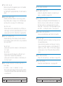
This is not another Users’ Guide for a new camera;
the following pages should offer information about
the results of integration more than a quarter century
of expertise into our well known and appreciated
camera body. Many things have changed in the world
of cinematography since the introduction of the COMPACT at the early 90ies. Following the launching of
the MOVIECAM SL, our company developed among
others the ARRICAM family of tools for contemporary
cinematographers’ demands, including the STUDIO and
the LIGHT camera bodies as well as a wide-ranging
array of accessories. The latest technologies in optical
construction and electronic design as well as the state
of the art video technology have been extensively integrated in those ARRICAM cameras. This latest expertise
enables us to offer an equivalent up-grading package
to all COMPACT owners. To achieve this, at ARRI
– MOVIECAM SERVICE CENTER headquarters, older
cameras are totally dismantled and not only rebuilt with
new components, but furthermore a lot of complementary controls and features are implemented.
Because the three perforation image acquisition technology seems to have a strong revival now, both ARRICAM cameras as well as the upgraded MOVIECAM
COMPACT Mk2 enable shooting either with 4 or 3
perforation pull-down.
The “Mk2 updating package” contains among others
the following key improvements:
• Replacement of the Viewfinder by a newly developed
brighter optical system. The Mk2 Viewfinder (not
compatible with other camera types) offers a much
brighter and even illuminated Ground Glass image.
PREFACE
4
PREFACE
MOVIECAM COMPACT Mk2
04/2007
04/2007
MOVIECAM COMPACT Mk2
5
Also the Eyepiece is larger, enabling a more comfortable viewing, especially from the side. The Eyepiece
also contains the Heater so that it cannot drop.
Complementary to the dioptre adjustment integrated
in the Eyepiece, the exchangeable Eyecups allow the
insertion of an individual dioptre lens. The ARRICAM
Studio Extension Viewfinder Tubes – short, long with
zoom, and long with zoom and with anamorphic unsqueezer lens – can be mounted between the Mk2
Viewfinder Arm and the Mk2 Eyepiece. The ARRICAM Studio Eyepiece will not perform as well as the
Mk2 one in this configuration.
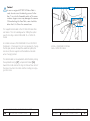
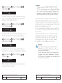
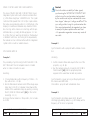
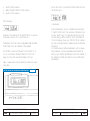
MOVIECAM COMPACT Mk2 CHECKLIST
The checklist (see button in the DOWNLOAD AREA)
which is ready to be printed out, gives a general overview of all modular parts of the MOVIECAM COMPACT Mk2 and might be of help when placing your
order.
• The Mk2 Video Assist is based on the ARRICAM ST
one. Beside the fact that some ARRICAM features like
In-Camera Slate or electronic shutter angle adjustments are not provided in the COMPACT Mk2, most
of the controls and features are similar. Even though
the Mk2 Video Assist is exclusively made for this
camera and cannot be mounted on the ARRICAM ST
Viewfinder, two connectors enable to plug-in either
a MOVIECAM or an ARRI On-board Video Assist
Monitor.
• The Mk2 Camera Control Board includes all controls
necessary to carried out e.g. speed or iris ramps.
Also all synchronization setups are adjusted there.
This makes the old COMPACT Syncobox and Speed
Control Box obsolete.
• Exchangeable movement: The COMPACT Mk2 can
be prepared to shoot with 4 or 3 perforation pull
down by ARRI – MOVIECAM SERVICE CENTER
trained maintenance personnel at any rental houses.
PREFACE
6
PREFACE
MOVIECAM COMPACT Mk2
04/2007
04/2007
MOVIECAM COMPACT Mk2
7
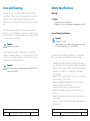
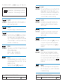
Safety Specifications
The MOVIECAM COMPACT Mk2 is almost maintenance-free. There is only one requirement for a smooth
operation: the camera has to be meticulously clean.
Therefore you should protect it against any dirt or smudges.
Warnings
Clean the camera exterior e.g. with window cleaner
(caution – do not moisten connectors!). Only when really necessary, e.g. to remove camera tape, gum, should
you use alcohol or benzine.
Caution!
Never use acetone!
When applied properly, compressed air is the best
cleaner; a vacuum cleaner or an air syringe will do fine.
Cotton tips, orangewood sticks, soft and hard brushes
may be used for gentle cleaning.
Caution!
The camera may be lubricated at a MOVIECAM
rental house only!
PREFACE
8
▲
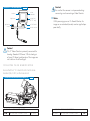
Care and Cleaning
Notice
• Operational error possible!
• Danger of injury or equipment damage possible!
General Safety Specifications
Caution!
Danger of injury!
Never place your hand in the lens port or inside
of the camera while it is RUNNING.
In order to ensure optimal performance, it is essential
that you acquaint yourself with this Users’ Guide.
• Assembly and initial operation should be carried out
only by persons who are familiar with the equipment!
• Switch OFF the camera MAIN switch before making
electrical connections (i.e. plugging on electrical
accessories)!
• Never RUN the camera without a lens or a protective
cap mounted in the lens port.
• Never operate the movement locking mechanism
while the camera is RUNNING!
• Ensure that the camera is securely mounted!
• Remove the battery cable before transport or servicing!
• Repairs should be carried out only by authorized service centres!
• Use only original MOVIECAM replacement parts and
accessories!
PREFACE
MOVIECAM COMPACT Mk2
04/2007
04/2007
MOVIECAM COMPACT Mk2
9
Important Notes
• In wet weather the normal safety precautions for handling electrical equipment should be taken.
• Avoid operational errors!
• Clean optical surfaces only with a lens brush or a
clean lens cloth! In case of solid dirt moisten a lens
cloth with pure alcohol.
• Do not use solvents to clean the film gate!
• Do not remove any screws which are secured with
paint!
PRODUCT SPECIFICATIONS
In case of enquiries or when ordering parts, please
advise camera serial number and model.
▲
Notice
This Users’ Guide applies to the MOVIECAM Mk2
as well as the whole MOVIECAM Accessory range.
PREFACE
10
PREFACE
MOVIECAM COMPACT Mk2
04/2007
04/2007
MOVIECAM COMPACT Mk2
11
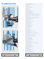
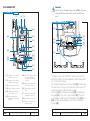
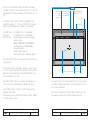
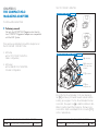
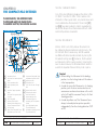
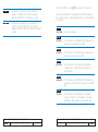
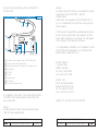
THE COMPACT Mk2-SYSTEM
1 2
47
3
4 47
5
6
7
8
9 10 11 12 13 14 15 16 17 18
19
9
2
20 6 21 22 23 24 25
10 29
5
12 13 30 16
26 27 28
31
THE COMPACT Mk2 SYSTEM
12
MOVIECAM COMPACT Mk2
1
2
3
4
5
6
7
8
9
10
11
12
13
14
15
16
17
18
19
20
21
22
23
24
25
26
27
28
29
30
31
32
33
34
35
36
37
38
39
40
41
42
43
44
45
46
47
48
49
50
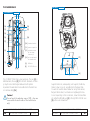
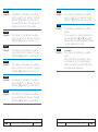
1000/300 magazine
magazine digital footage counter
video assist
read out unit
on board 2“ video monitor
auxiliary handle
zoom lens
matte box mounted on rods
camera main switch (on/off)
power receptacle (24 V)
camera control board and displays
accessory connector – covered (e.g. for power distribution box)
accessory connector – covered (e.g. for time code box)
sliding plate
accessory attachment (e.g. for upper carrying handle)
lightweight base plate/rod holder
side carrying handle
follow focus
400/120 lightweight magazine
camera connectors
video assist connectors
run/stop button
video assist menu/store dial
upper carrying handle
video assist ccd cover
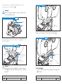
viewfinder arm
prime lens
lightweight matte box
padded shoulder rest (velcro attachment)
tape measure hook
right handgrip (mounted on rosette) with r/s button
filter holder
zoom ring on studio zoom extension tube
diopter adjustment barrel on eyepiece
eyecup
manual footage indicator
mask movielite module
top mount adapter with handle
pair of long rods
dust check/take-up button
connectors (for eyepiece heater or assistant work light)
camera door lock
viewfinder levelling rod
eypiece bayonet mount
eyepiece with heater connector
rear mount adapter
magazine latch
left handgrip mounted on rods
pair of short rods
magazine/adapter mounting rail
THE COMPACT Mk2 SYSTEM
04/2007
04/2007
MOVIECAM COMPACT Mk2
13
1
2
3
4
5
6
7
8
9
10
11
12
13
14
15
16
17
18
19
20
21
22
23
24
25
26
27
28
29
30
31
32
33
34
35
36
37
38
39
40
41
42
43
44
45
46
47
48
49
50
1000/300 magazine
magazine digital footage counter
video assist
read out unit
on board 2“ video monitor
auxiliary handle
zoom lens
matte box mounted on rods
camera main switch (on/off)
power receptacle (24 V)
camera control board and displays
accessory connector – covered (e.g. for power distribution box)
accessory connector – covered (e.g. for time code box)
sliding plate
accessory attachment (e.g. for upper carrying handle)
lightweight base plate/rod holder
side carrying handle
follow focus
400/120 lightweight magazine
camera connectors
video assist connectors
run/stop button
video assist menu/store dial
upper carrying handle
video assist ccd cover
viewfinder arm
prime lens
lightweight matte box
padded shoulder rest (velcro attachment)
tape measure hook
right handgrip (mounted on rosette) with r/s button
filter holder
zoom ring on studio zoom extension tube
diopter adjustment barrel on eyepiece
eyecup
manual footage indicator
mask movielite module
top mount adapter with handle
pair of long rods
dust check/take-up button
connectors (for eyepiece heater or assistant work light)
camera door lock
viewfinder levelling rod
eypiece bayonet mount
eyepiece with heater connector
rear mount adapter
magazine latch
left handgrip mounted on rods
pair of short rods
magazine/adapter mounting rail
THE COMPACT Mk2 SYSTEM
14
MOVIECAM COMPACT Mk2
THE COMPACT Mk2-SYSTEM
8 32
7
6
39
5
18
1 33 34 35 36 4 37 38
26 40 41 22 30 42
8 32 27 26 44 34 41 24 46
48
49
16 22
42
6
19
29
43
47
50
THE COMPACT Mk2 SYSTEM
04/2007
04/2007
MOVIECAM COMPACT Mk2
15
CHAPTER 1
THE BODY OF THE COMPACT Mk2
SYSTEM
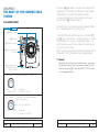
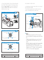
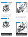
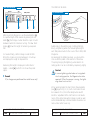
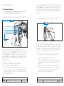
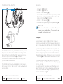
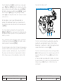
THE CAMERA FRONT
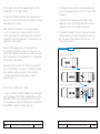
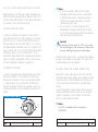
A lens port [4] type ARRI PL is built into the camera front.
Depending on the mounting of the port, shooting either
STANDARD 35 or SUPER 35 format is possible.
To remove the port cap or the lens itself, turn the two
bayonet levers [5] counter-clockwise.
To mount a lens, turn the levers gently clockwise until the
lens is seated properly. Do not use force!
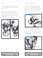
CAMERA FRONT fig.1/1
[5] lens port levers
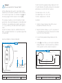
To the left of the lens port there are two connectors [1]
and [2]. The 3-pins Fischer connectors have a 24 V outlet protected by an on-chip circuitry rated at max. 4 A
and they may be used for any remote-controlled device,
e.g. zoom or focus drive.
Both connectors may also be used for the remote control
of the RUN/STOP (RS) button (e.g. handgrip button).
[4] lens port
[3] accessory bracket
[2] R/S connector and
24 V outlet
▲
[1] connector for right
handgrip R/S button
and 24 V outlet
Remark
Based on the wish by some rental houses, a number
of cameras have a 2-pin connector instead of 3-pin
next the lens port [2] – then the RUN/STOP function
is not supported there.
camera front 24 V supply outlet (female) Top View
GND
+24 V
(2 Amps. max.)
R/S Connectors
Socket type:
FISCHER D 103 A 051
(Handgrip [1] and Power Distribution
Box – see page 23)
+ 24 V/2 AMP MAX.
ON/OFF
GND
Socket type:
FISCHER D 102 A 052
1 – THE BODY OF THE COMPACT Mk2 SYSTEM
16
MOVIECAM COMPACT Mk2
04/2007
1 – THE BODY OF THE COMPACT Mk2 SYSTEM
04/2007
MOVIECAM COMPACT Mk2
17
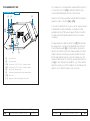
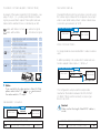
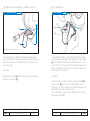
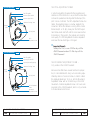
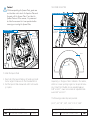
The camera door is located at the camera left side. When it
is closed, the door lock [10] must be flush with the door;
a Velcro attachment keeps the lock in this position.
THE CAMERA LEFT SIDE
THE CAMERA LEFT SIDE
[5]
fig.1/2
[8]
[11]
Power (24 V) for Eyecup Heater and Assistant Work Light is
supplied via two connectors [7a] + [7b].
In case of an external short circuit, e.g. when Eyecup Heater
or Assistant Work Light is defective, an electronical fuse
automatically cuts off the power supply of these connectors.
The total load (both outputs together) should not increase
1 Ampere.
[7a]
[7b]
[6]
The tape measure is attached to the hook [9] that indicates
the image plane. The film will be tightened when the Dust
Check/Take-Up button [8] is shortly pressed. By pressing
about 3 seconds the Dust Check/Take-Up button, the mirror
shutter is cleared out of the way and thus permits to check
the film gate without having to open the camera door. The
camera is switched to run or stop by pushing either the button [6] or some other Run/Stop buttons, e.g. at the camera
right side. Equally, any of those buttons can be employed to
switch to run or stop the camera, and vice versa.
[9]
[5]
lens port lever
[6]
run/stop button
[7a]
connectors 24 V/500 mA – electronic-fused
[7b]
connectors 24 V/500 mA – electronic-fused
[8]
dust check/take-up button
[9]
indication of image plane/tape measure hook
[10] door lock
[11] magazine-/top mount adapter connector
1 – THE BODY OF THE COMPACT Mk2 SYSTEM
18
MOVIECAM COMPACT Mk2
04/2007
1 – THE BODY OF THE COMPACT Mk2 SYSTEM
04/2007
MOVIECAM COMPACT Mk2
19
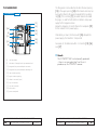
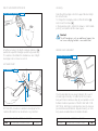
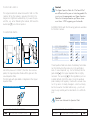
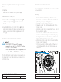
THE CAMERA REAR
THE CAMERA REAR
fig.1/3
[11]
[15]
[14]
[16]
[9]
[13]
[17]
[18]
[12]
[19]
[6]
The Magazines can be attached to either the rear opening
[13] or the upper opening [14] at the camera rear resp. top
by mounting them (or Magazine Adapter) to the mounting
rail [12]. The connector [11], mounted mobile to facilitate
the plug-in, is used for both electronic interface and power
supply for the magazine drives.
Below the magazine connector there is the receptacle [19]
for the camera’s 24 V power supply.
Protected by a crown, the Main switch [18] interrupts the
power supply of all electronic components.
See page 23 for details about the 3 connectors [15], [16]
and [17].
▲
[6]
run/stop button
[9]
indication of image ilane/tape measure hook
[11] magazine-/top mount adapter connector
Remark
The COMPACT Mk2 is electronically protected
– there is no more glass-tube fuse like in its
predecessor, the COMPACT camera.
[12] magazine-/top mount adapter mounting rail
[13] rear camera opening
[14] upper camera opening
[15] video-in connector (sync)
[16] sync-In connector
[17] sync-out connector
[18] main switch
[19] power receptacle
1 – THE BODY OF THE COMPACT Mk2 SYSTEM
20
MOVIECAM COMPACT Mk2
04/2007
1 – THE BODY OF THE COMPACT Mk2 SYSTEM
04/2007
MOVIECAM COMPACT Mk2
21
SUPPLEMENTARY POWER DISTRIBUTION BOX
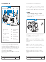
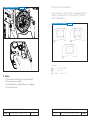
THE CAMERA RIGHT SIDE
THE CAMERA RIGHT SIDE
[17] [16] [15]
fig.1/4
[20][21]
[22]
[9]
[5]
The little cover [21] can be replaced by the Power Distribution Box. The three supplementary 3-pins Fischer R/S connectors have 24 V outlets to supply power to further accessories.
▲
Remark
Be aware that the total load for the five power
outlets (two at the front and the three supplementary)
together is max. 4 A.
[23]
THE POWER DISTRIBUTION BOX
fig.1/5
[18] [19] [24]
[5]
lens port lever
[9]
image plane/tape
measure hook
[15] video-in connector
(Sync)
[16] sync-in connector
[17] sync-out connector
[18] main switch
[20] camera control board
and displays
[21] upper cover of
accessory connector
[22] upper carrying
handle attachment
[23] right handgrip rosette
[24] lower cover of
accessory connector
[19] power receptacle
The Upper Carrying Handle is attached to the threaded
sockets and gauged boreholes [22] located on top of the
camera right side as well as on the Backload Adapter; the
Right Handgrip is screwed into the threaded socket in the
right handgrip rosette centre [23].
Below the cover plates [21] and [24] there are the connectors for accessories.
1 – THE BODY OF THE COMPACT Mk2 SYSTEM
22
MOVIECAM COMPACT Mk2
04/2007
A Plexiglas panel covers the Camera Control Board and
displays [20] (see chapter 11 page 197).
[15] Plug in a BNC Video cable for carrying on the appropriate video signal so to enable the camera to be synchronized with it.
[16] Plug in a cable with a 4-pin Fischer connector to
enable the camera to be synchronized with an external sync
device (e.g. pulse generator) or with another camera.
[17] Plug in a cable with a 5-pin Fischer connector to
forward the camera pulse to another device, e.g another
camera.
1 – THE BODY OF THE COMPACT Mk2 SYSTEM
04/2007
MOVIECAM COMPACT Mk2
23
THE CAMERA TOP
THE CAMERA TOP
Caution!
Do not touch the adjusting screws [46] – they are
reserved for the technicians of the rental house
only!
fig.1/6
[11]
[13] [12]
THE VIEWFINDER MOUNTING PLATE
[46]
[47]
fig.1/7
[49]
[47]
[14]
[50]
[51]
[51]
[49]
[52]
[49]
[46]
[49]
[48]
[51]
[49]
[50]
[51]
[49]
[53]
[52]
[53]
[11] magazine-/top mount
adapter connector
[12] magazine-/top mount
adapter mounting rail
[13] rear camera opening
[14] upper camera opening
[46] adjusting screws (for
rental house only!)
[47] backload adapter
attachment (threaded
sockets)
[48] backload adapter and
top mount adapter
attachment (threaded
sockets)
[49] viewfinder attachment
(threaded sockets)
[50] glass surface (viewfinder)
[51] viewfinder attachment
(gauged boreholes)
[52] viewfinder connector
[53] engraved viewfinder
mounting plate
1 – THE BODY OF THE COMPACT Mk2 SYSTEM
24
MOVIECAM COMPACT Mk2
04/2007
The plate on top of the COMPACT Mk2 body shows the
format the camera has been adjusted to (either STANDARD
35 or SUPER 35 format).
The engraved Viewfinder Mounting Plate [53] is turned upside down when changing the format at a rental house. The
Viewfinder system is attached to the gauged
boreholes [51] and threaded sockets [49] and flanged to
the plate [53] on top of the glass surface [50]. The Backload Adapter is attached to the threaded sockets [47] and
[48], the Top Mount Adapter only to the front threaded
sockets [48].
1 – THE BODY OF THE COMPACT Mk2 SYSTEM
04/2007
MOVIECAM COMPACT Mk2
25
Caution!
The format should be changed at a rental house
only! The Lens Mount and – by turning the mount
plate upside down – also the viewfinder mount
will be adjusted. Now, the engraving indicates
the new format.
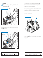
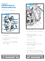
CLEANING THE LIGHT PASS
fig.1/8
On top of the housing, next to the window, four screws
enable to open the housing in order to clean the light pass.
This operation has to be carried out preferably by maintenance personnel at the rental house.
OPERATION
1. Disconnect the camera from the power supply
2. Remove the four M2.5 screws located next to the window
3. Insert the MOVIECAM TOOL and screw in the M3
screw driver in one of the boreholes
4. Pull carefully the tool straight out in order to raise the optical block out of the cavity
5. Clean carefully all glass surfaces
6. Reintroduce the optical block and push it carefully into the
cavity until it sits correctly on its holder
7. Place the cover on top of the block and secure it with the
four M 2.5 screws.
special metric screws M 2.5
threaded boreholes
with 3 mm threads
1 – THE BODY OF THE COMPACT Mk2 SYSTEM
26
MOVIECAM COMPACT Mk2
04/2007
1 – THE BODY OF THE COMPACT Mk2 SYSTEM
04/2007
MOVIECAM COMPACT Mk2
27
THE CAMERA BASE
THE CAMERA BASE
BASE PLATE
fig.1/10
fig.1/9
[54]
[54]
[55]
[55]
[54]
[54]
[54]
[55]
[54] threaded sockets
[19] power receptacle
[56]
[55] adjusting screws
(for the rental
house only!)
[56] velcro attachment
for shoulder rest
[19]
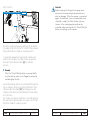
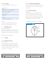
[A] [B]
[A]
ARRI axis
[B]
MOVIECAM axis
AllgSicht2
[57]
[58]
The COMPACT Mk2 has a dual axis base. The axis [A] is
ARRI standard, the axis [B] MOVIECAM standard. Accessory may thus be interchanged between both systems.
A padded Shoulder Rest can be attached to the black Velcro adhesive strip [56].
Caution!
Do not touch the adjusting screws [55] – they are
reserved for the technicians of the rental house
only!
1 – THE BODY OF THE COMPACT Mk2 SYSTEM
28
MOVIECAM COMPACT Mk2
04/2007
Support Rods and, subsequently, Lens Support, Matte Box,
Studio Follow Focus etc. are attached to the Base Plate.
You will not need the Base Plate when using Prime Lenses,
flanged Filter Holders, Sunshades and Lightweight Follow
Focus. Depending on the accessories, screw the Base Plate
into either the left ARRI axis [A] or the right MOVIECAM axis
[B] with a wide screwdriver.
1 – THE BODY OF THE COMPACT Mk2 SYSTEM
04/2007
MOVIECAM COMPACT Mk2
29
Caution!
In case no original MOVIECAM Base Plate is
used, do not screw the attaching screws further
than 7 mm into the threaded sockets of the camera base. Longer screws may damage the camera.
When attaching the Base Plate, care should be
taken that it sits flat on the camera base.
ADJUSTABLE MOVIECAM BASE PLATE
fig.1/11
[57]
[58]
The Support Rod brackets on the MOVIECAM Base Plate
are mobile. This is of advantage when shifting the optical
axes for shooting in either STANDARD 35 or SUPER 35
format.
As centers and axes of the STANDARD 35 and SUPER 35
format are 1,27mm apart, it is not only necessary to change
the film gate, but also to adapt the viewfinder system, the
lens mount, the lens support and the matte box brackets
when changing format.
White = STANDARD 35format
Red = SUPER 35 format
The Rod brackets can be adjusted to either format by turning
the asymmetrical rings [57]. Just press both sliders [58]
toward the centre and turn the rings so that each two dots of
the same colour face the centre and the locating pins engage in the holes.
1 – THE BODY OF THE COMPACT Mk2 SYSTEM
30
MOVIECAM COMPACT Mk2
04/2007
1 – THE BODY OF THE COMPACT Mk2 SYSTEM
04/2007
MOVIECAM COMPACT Mk2
31
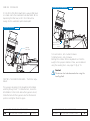
CHAPTER 2
THE COMPACT Mk2
VIEWFINDERS
The MOVIECAM Viewfinder System – built exclusively
for the COMPACT Mk2 – has two components:
A) The Mk2 OPTICAL VIEWFINDER
B) The Mk2 100% VIDEO ONLY VIEWFINDER
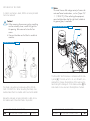
The Mk2 OPTICAL VIEWFINDER
OPTICAL VIEWFINDER fig.2/1
viewfinder
eyepiece
viewfinder arm
2 – THE MOVIECAM Mk2 VIEWFINDERS
32
MOVIECAM COMPACT Mk2
The new Mk2 Optical Viewfinder offers an exceptional
viewing quality favoured by a large optical design. Special care has been taken to enable a bright image and
to avoid the unpleasant vignette effect that could occur
by looking from the side.
The Mk2 Optical Viewfinder permits the use of an
Eyepiece (mounted on the Viewfinder Arm) and an
Mk2 Video Assist Camera (mounted to the right side)
at the same time. This combination gives the operator
the choice between the possibility of using the optical
image as well as the video image or only to use one of
the two images alone. The video option would be chosen when looking through the Viewfinder is not possible
or not desirable – e.g. STEADICAM® or remote head
operation. To work with the “flexibility of a mini-HDV
camera”, the operator can use an On-Board Monitor
instead of looking through an Eyepiece.
Light transmission of the built-in beam splitter has a ratio
of 80% for the eyepiece and 20% for the video camera.
Even though a Long Zoom Anamorphic Extension Tube
with a swing-away de-squeezer is attachable on this
Viewfinder Arm, the Mk2 Optical Viewfinder is mainly
foreseen for use with spherical lenses.
2 – THE MOVIECAM Mk2 VIEWFINDERS
04/2007
04/2007
MOVIECAM COMPACT Mk2
33
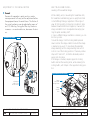
ERGONOMY
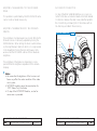
THE Mk2 VIEWFINDER’S HOUSING
In order to adjust the Eyepiece position for a comfortable viewing, the Viewfinder Arm can be rotated, extended and swivelled.
On the left side of the Viewfinder a MOVIELITE module
attachment is covered by a removable cover plate.
Unscrew the 5 mm hex screws with an S4 Allen key to
remove the cover plate and to mount the MOVIELITE
module – see page 55 fig. 3/2.
The Arm - it can be rotated and swivelled to both
sides of the camera - is permanently mounted to the
Viewfinder by means of a hinge. This hinge enables to
swivel the arm on the other camera side while a 1.000
ft/300 m Magazine is mounted on top.
ROTATION AND SWIVEL
VIEWFINDER LEFT SIDE
fig.2/3
cover of the
MOVIELITE
attachment
fig.2/2
On the right side of the Viewfinder a Video Assist attachment is covered by a removable cover plate. Unscrew
the two 5 mm hex screws with an S4 Allen key to remove the cover plate to mount the Video Assist Camera
– see page 76 fig. 4/5.
rotation
VIEWFINDER FROM THE TOP
swivel
fig.2/4
cover of the
video assist
attachment
2 – THE MOVIECAM Mk2 VIEWFINDERS
34
MOVIECAM COMPACT Mk2
2 – THE MOVIECAM Mk2 VIEWFINDERS
04/2007
04/2007
MOVIECAM COMPACT Mk2
35
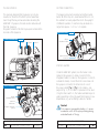
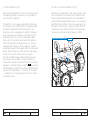
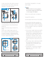
VIEWING FILTER LEVER
ARM ROTATION FRICTION KNOB
fig.2/6
On the front of the Mk2 Viewfinder a viewing filter lever
is located next to the Viewfinder Arm attachment. When
depressing the filter lever, an ND 0.6 filter will be
swung into the viewfinder optical beam path.
VIEWING FILTER LEVER
fig.2/5
viewfinder arm
rotation friction
knob
viewing
filter lever
To loosen tension, turn counter-clockwise.
To tighten tension, turn clockwise.
Although this rotation friction adjustment can hold the
weight of an Eyepiece Extension Tube, we recommend
using the Levelling Rod – see page 70 fig.3/15.
Caution!
The tension has to be loosened when using the
Levelling Rod!
PIVOTING THE VIEWFINDER ARM – The friction adjustment
The Eyepiece mounted on the Viewfinder Arm rotates
vertically through 360°. To rotate the Arm, loosen the
Arm Rotation Friction knob below the Eyepiece mount,
rotate the Arm until the Eyepiece reaches the desired
position and tighten the knob again.
2 – THE MOVIECAM Mk2 VIEWFINDERS
36
MOVIECAM COMPACT Mk2
2 – THE MOVIECAM Mk2 VIEWFINDERS
04/2007
04/2007
MOVIECAM COMPACT Mk2
37
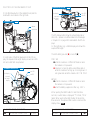
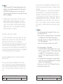
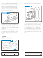
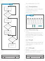
EXTENDING THE VIEWFINDER ARM – the telescopic
adjustment
On the Mk2 Viewfinder Arm, an extending feature
allows the Eyepiece to move in and out from the camera body to facilitate left or right eye viewing. The Arm
can be telescoped up to approximately 36 mm. Shifting
does not change size, sharpness or quality of the view
finder image.
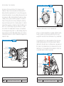
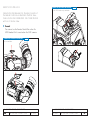
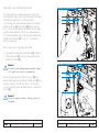
SWIVELLING THE VIEWFINDER ARM
The Viewfinder Arm can be swivelled in order to raise
the viewing axe or to place the Eyepiece on the right
side of the camera. When a 1000/300 Magazine is
mounted on top of the camera, the orientable Viewfinder Arm has to be tilted forward in order to be able to
swing the Arm over to the other side of the camera.
HINGE RELEASE KNOB
THE TELESCOPIC ADJUSTMENT
fig.2/8
fig.2/7
fix
loose
hinge
release
knob
➞
➞
viewfinder arm
telescope knurled
adjusting ring
To extend or reduce the Viewfinder Arm length, turn the
knurled ring towards the position labelled loose, then
pull or push the Arm elbow to the desired length and
retighten the knurled ring.
2 – THE MOVIECAM Mk2 VIEWFINDERS
38
MOVIECAM COMPACT Mk2
OPERATION
1. Loosen the Arm Rotation Friction knob first.
2. Then turn the Arm upwards to place the Eyepiece in
its vertical position.
3. Now press the hinge release knob – the brake opens
automatically when the hinge is “open” – and swing
the Arm carefully forward.
4. After pivoting the Arm to the other side of the camera, close the Viewfinder again. It locks automatically
when a fixing pin entered one of the gauged holes.
2 – THE MOVIECAM Mk2 VIEWFINDERS
04/2007
04/2007
MOVIECAM COMPACT Mk2
39
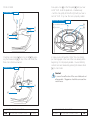
ADJUSTMENT OF THE SWIVEL FRICTION
▲
ERECT IMAGE VIEWFINDER –
Levelling of the viewfinder image
Remark
Because this operation is quite sensitive, maintenance personnel will carry out the adjustment before
the equipment leaves the rental house. The friction of
the swivel mechanism can be adjusted by means of
an S1.5 Allen key. Turning the Allen key clockwise
increases – or counter-clockwise, decreases the tension.
VIEWFINDER ARM HINGE
fig.2/9
While rotating and/or swivelling the Viewfinder Arm,
the Viewfinder automatically give an upright erect and
correct left-to-right image, regardless of the angle of
view. When mounting or removing an Extension Tube
between Viewfinder Arm and Eyepiece, however, the
image orientation has to be adjusted manually by turning the prism assembly 180°.
In case a different image orientation is desired, you can
turn it as you like.
To level the image, hold the locking button pressed
down and turn the image rotation knob until the image
is levelled as you wish. To re-activate the automatic
image levelling, turn the image levelling knob until it
locks in one of the locking positions. There are positive
stops at 0° and 180°, so that the standard positions
easily click into place.
If the image is inverted, depress again the locking
button and turn the levelling knob, while releasing the
locking button, until it stops in the opposite locking position.
IMAGE ORIENTATION ADJUSTMENT
fig.2/10
Image
orientation
locking button
adjustment
screw of the
swivel friction
Image
rotation
knob
2 – THE MOVIECAM Mk2 VIEWFINDERS
40
MOVIECAM COMPACT Mk2
2 – THE MOVIECAM Mk2 VIEWFINDERS
04/2007
04/2007
MOVIECAM COMPACT Mk2
41
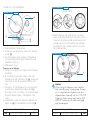
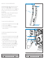
The Mk2 EYEPIECE
DIOPTER CORRECTION
The specially designed Mk2 Eyepiece can only be
mounted on the Arm of the Mk2 Optical Viewfinder.
Even though the bayonet would enable mounting the
ARRICAM ST Eyepiece, the best result is obtained with
this Mk2 Eyepiece.
Magnetic holders for the Mk2 Eyecup are located at the
rear side of the Eyepiece.
The Eyepiece may be focused by turning the knurled
barrel. With the help of a scale labelled from 1 to 12,
the assistant can easily adjust the lens to the eyesight
of different operators. Corrections may be made in a
range from approx. - 5.5 to + 5.5 dioptres.
EYEPIECE CONFIGURATION fig.2/11
eyecup
eyepiece
bayonet
MOVIECAM EYEPIECE fig.2/13
diopter
adjustment barrel
eyepiece heater
connector
EYEPIECE HEATER
Unlike the ARRICAM System, here the heater is integrated in the Eyepiece. A cable connector for the
integrated heater is located on the Eyepiece. In order to
activate the heater, connect the short coiled cable into
the Eyepiece connector, the other end into one of
the power outlets [7a] or [7b] on the camera – see
page 18 fig. 1/2. No switch is provided. When switching the Main switch on, the heater automatically activates, preventing so the entry pupil from fogging in low
temperatures, e.g. when filming outdoors in winter.
OPTICAL VIEWFINDER fig.2/12
diopter
adjustment barrel
eyepiece
shetter lever
Caution!
If the camera is powered by battery, it is recommended to switch off the eyecup heating during
extended breaks in filming.
magnetic holder for
eyecup
2 – THE MOVIECAM Mk2 VIEWFINDERS
42
MOVIECAM COMPACT Mk2
2 – THE MOVIECAM Mk2 VIEWFINDERS
04/2007
04/2007
MOVIECAM COMPACT Mk2
43
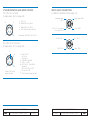
EYEPIECE SHUTTER
The Mk2 EYECUP
By moving the lever, an integrated shutter mechanism
enables to protect the eyepiece and prevents light from
entering the camera.
The rubber cushion Mk2 Eyecup can only be mounted
on the Mk2 Eyepiece. This Eyecup is held by magnets
located around the exit pupil.
EYEPIECE SHUTTER
fig.2/14
eyepiece
shutter lever
eyepiece
shutter blade
To clean the entry pupil, remove the Eyecup by simply pulling it straight out. Eye friendly covers, such as
chamois or cotton cloth, can be easily attached with
a rubber band. Another useful cover are the terry cloth
“wrist bands“, well-known from tennis, as they are sweat
absorbing, reusable and easy to attach.
EYECUP RETAINING MOUNT
Into the rubber Eyecup there is a cavity in which a dioptre correction lens or a special filter can be fastened with
an adhesive. This operation is carried out by trained
maintenance personnel only. The optical component
must have a diameter of 23.4 mm ± 0.1 mm.
2 – THE MOVIECAM Mk2 VIEWFINDERS
44
MOVIECAM COMPACT Mk2
2 – THE MOVIECAM Mk2 VIEWFINDERS
04/2007
04/2007
MOVIECAM COMPACT Mk2
45
MOUNTING THE EYEPIECE
EYEPIECE MINI PL BAYONET MOUNT fig.2/16
bayonet
locking
lever
UNLOCK
OPEN
bayonet
locking
lever
LOCK
EYEPIECE BAYONET MOUNT
UNLOCK safety button
➡
By means of a bayonet mount, the Eyepiece and
Extension Tubes can be mounted and removed effortlessly from the Viewfinder Arm. To mount the Eyepiece,
remove the protection cap by rotating the bayonet counter-clockwise. After checking that both parts are immaculately clean, gently insert the Eyepiece or Extension
Tube into the port and lock it by rotating the retaining
bayonet clockwise until it is correctly seated. In order to
prevent the Eyepiece or Extension Tube from falling out
when it is not held firmly during its removal, an additional UNLOCK safety button has been incorporated
into the Eyepiece bayonets. So, after rotating partly the
bayonet lever, push the little safety button and continue
rotating the bayonet in order to release the Eyepiece or
Extension Tube.
The Mk2 100% VIDEO ONLY VIEWFINDER
When no Optical Viewfinder is needed, the Mk2 Video
Assists Camera can be mounted directly to the lightweight MOVIECAM Mk2 100% Video Only Viewfinder.
This Viewfinder has no beam splitter and thus provides
100% light transmission for the Video Assist Camera
attached to the right side. No filter wheel is provided on
the Video Only Viewfinder and no Readout Unit can be
attached on it. A receptacle for the Remote Control Box
is provided under a small cover plate.
fig.2/15
bayonet
locking lever
UNLOCK
safety button
100% VIDEO ONLY VIEWFINDER
fig.2/17
bayonet
locking lever
cover of the
connector
for remote
control box
2 – THE MOVIECAM Mk2 VIEWFINDERS
46
MOVIECAM COMPACT Mk2
2 – THE MOVIECAM Mk2 VIEWFINDERS
04/2007
04/2007
MOVIECAM COMPACT Mk2
47
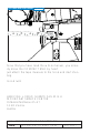
MOUNTING THE OPTICAL VIEWFINDERS OR THE
100% VIDEO ONLY VIEWFINDER
On the base of both Viewfinders, the Viewfinder’s window, the connector, the fixing pins and retaining screws
are protected by a cover.
After removing the protection covers (fixed with two
5 mm hex screws) and checking that both parts (connectors, glass surfaces) are absolutely free of dust and
fingerprints, mount the Viewfinder or 100% Video Only
Viewfinder on the camera.
The pins must engage easily in the gauged holes.
While tightening the three 5 mm hex screws, the connectors will fit together automatically. Therefore be sure
that the Viewfinder or the 100% Video Only Viewfinder
sits securely on the camera.
Because the MOVIECAM Mk2 offers the possibility to
shoot in STANDARD 35 format or in SUPER 35 format,
the Viewfinder must be mounted to fit these formats
– see the Viewfinder Mounting Plate in chapter 1,
page 25, fig. 1/7.
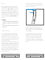
1. The Studio Medium Extension Tube brings the entry
pupil of the Eyepiece about 15 cm/5.9” behind the
film plane.
2. The Studio Zoom Extension with variable image
magnifier (2x) brings the entry pupil of the Eyepiece
about 30 cm/11.8” behind the film plane.
3. The Studio Anamorphic Extension Tube with variable
image magnifier and flip-in de-squeezer lens brings
the entry pupil of the Eyepiece about 30 cm/11.8”
behind the film plane.
EXTENSION TUBES
fig.2/18
ST medium extension tube
ST long zoom extension tube
levelling rod attachment
ST long zoom anamorphic extension tube
THE EYEPIECE EXTENSION TUBES
In order to extend the distance between the Viewfinder
and the Eyepiece, MOVIECAM suggests the use of the
ARRICAM STUDIO bayonet-mounted Extension Tubes.
The three Extension Tubes are fitted with a receptacle for
the ARRICAM Eyepiece Levelling Rod, are:
2 – THE MOVIECAM Mk2 VIEWFINDERS
48
MOVIECAM COMPACT Mk2
zoom ring
anamorphic/
spherical lever
2 – THE MOVIECAM Mk2 VIEWFINDERS
04/2007
04/2007
MOVIECAM COMPACT Mk2
49
▲
Notice
• Both the Zoom and Anamorphic Extension Tubes
have built-in magnifiers that allow even more critical eye-focusing. Turn the zoom ring to magnify the
image of the Ground Glass in a continuous range.
A mark on the ring indicates the standard image
size.
• It is recommended to use the zoom or magnifier
only when checking and not when shooting because only the centre part of the image appears in the
Eyepiece.
2 – THE MOVIECAM Mk2 VIEWFINDERS
50
MOVIECAM COMPACT Mk2
2 – THE MOVIECAM Mk2 VIEWFINDERS
04/2007
04/2007
MOVIECAM COMPACT Mk2
51
CHAPTER 3
THE MOVIECAM ACCESSORIES
to be attached to viewfinder
components
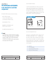
MOVIECAM offers several accessories including:
• two MOVIELITE modules,
1) The LCD MOVIELITE Module
2) The MASK MOVIELITE Module
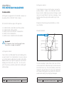
THE MOVIELITE MODULES
In order to make the frame lines of the Ground Glass
visible while shooting dark scenes, MOVIECAM provides small attachments for the Mk2 Viewfinder called
MOVIELITE. Two different MOVIELITE modules are provided; the differences between them are not only in the
design but also in the technology employed.
THE MOVIELITE MODULES
fig.3/1
• the Mk2 READOUT Unit,
• the REMOTE CONTROL Box with
its Mk2 Cable Connector,
LCD MOVIELITE Module
MASK MOVIELITE Module
• the VIEWFINDER LEVELLING ROD.
THE LCD MOVIELITE MODULE
▲
Remark
The MOVIECAM COMPACT REMOTE CONTROL
BOX works with both camera types, the COMPACT
and the COMPACT Mk2. But the Mk2 REMOTE
CONTROL BOX CABLE has to be used in order to
link the box to the Mk2 camera.
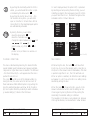
By means of a sophisticated electronic design, the LCD
MOVIELITE module fades in one or – simultaneously –
two luminous frame outlines. Besides those two frames,
also a reticule can be faded in and out the viewfinder
image by pushing the Crosshair button. Four frame outlines with the following aspect ratios are provided in the
LCD MOVIELITE:
1
1
1
1
3 – THE MOVIECAM ACCESSORIES
52
MOVIECAM COMPACT Mk2
:
:
:
:
1.33 (TV)
1.375 (Academy)
1.66 (European Wide Screen)
1.85 (US/UK Wide Screen)
3 – THE MOVIECAM ACCESSORIES
04/2007
04/2007
MOVIECAM COMPACT Mk2
53
▲
MOUNTING THE MOVIELITE MODULES
Important Remark
The LCD MOVIELITE Module is usable only for shooting in STANDARD 35 format (not for SUPER 35).
▲
THE MASK MOVIELITE MODULE
In order to satisfy special customer requests regarding
the Ground Glass marks with faded-in luminous frames,
another MOVIELITE module has been developed. The
formats to be faded in are not chosen electronically
but with the use of Masks (slides). Customer specific
format combinations that are not offered as „Standard
Masks” or in the electronic MOVIELITE can be produced
by MOVIECAM on order. The Masks created for the
Mk2 MOVIELITE are neither compatible with the ones
designed for previous MOVIELITE Modules nor with the
ARRICAM Framglow Module.
3 – THE MOVIECAM ACCESSORIES
54
MOVIECAM COMPACT Mk2
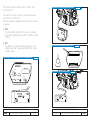
After removing both protection covers, attach the appropriate MOVIELITE module to the Viewfinder with one 5
mm screw (S4 Allen Key) [b].
Notice
Care should be taken that:
• The camera is switched OFF by camera MAIN
switch (also important when removing the MOVIELITE),
• Both glass surfaces [e] are absolutely clean,
• The pins [c] engage easily in the gauged holes [f]
and the connectors [d] are properly seated – only
then the MOVIELITE module sits correctly on the
Viewfinder!
MOUNTING THE LCD MOVIELITE
fig.3/2
3 – THE MOVIECAM ACCESSORIES
04/2007
04/2007
MOVIECAM COMPACT Mk2
55
The MOVIELITE memory stores the latest setup chosen,
even when the camera is disconnected. A luminous reticule can be switched on/off with button [c].
The brightness of the two luminous frames and the reticule may be continuously adjusted with the potentiometer
[b].
HANDLING THE LCD MOVIELITE MODULE
OPERATING THE LCD MOVIELITE
fig.3/3
[a] [b] [c]
HANDLING THE MASK MOVIELITE MODULE
The Mask MOVIELITE module inserts the luminous frame
outlines of a single or of combined aspect ratio(s) into
the viewfinder image. A set of Masks with different
aspect ratios and/or aspect ratio combinations is provided by MOVIECAM.
[d]
[a] Accessory bracket
[e]
[b] Dimmer
[c] On/off button for reticule
[d] Select 1
[e] Select 2
MOUNTING THE MASK MOVIELITE
fig.3/4
While the camera is powered and no figure is displayed on the MOVIELITE module, just push one of the
buttons, so the device shows the preselected aspect
ratio(s). By pressing the button “Select 1”, a luminous
frame appears on the ground glass. The display “Format
1” shows the aspect ratio. By pressing the button “Select
1” again, the other aspect ratios will be displayed.
In case a frame, e.g. 1 : 1,66, is already faded in and
you want to add another one, e.g. TV, just press the
button “Select 2” until the desired aspect ratio appears
in the display “Format 2”. Each of the frames mentioned
above may be switched on/off with either of the two
“Select” buttons.
3 – THE MOVIECAM ACCESSORIES
56
MOVIECAM COMPACT Mk2
3 – THE MOVIECAM ACCESSORIES
04/2007
04/2007
MOVIECAM COMPACT Mk2
57
▲
EXCHANGING THE MASK
In order to exchange a mask, first the accessory bracket
has to be removed.
Caution!
• When removing the accessory plug, everything
must be extremely clean; no dirt must get into
the opening. Take care not to lose the four
screws.
• Care must be taken as the Mask is sensible to
scratches.
HANDLING THE MASKS
Notice
The rental houses offer a large variety of various formats and format combinations, such as [Super 35/
1 : 1/85 & TV]. When collecting the equipment,
care should be taken that the right slide (suitable to
the ground glass) is available.
OPERATING THE MASK MOVIELITE
fig.3/6
[A]
[B]
fig.3/5
The Mask is mounted and removed with the MOVIECAM COMBITOOL. When mounting the Mask, care
must be taken that it is inserted until it touches the buffer.
The Mask MOVIELITE module is activated with the rotary knob [A]. This knob, which is no on/off switch, is a
dimmer that changes the brightness of the luminous frames from light to extinguish. In the small window [B] the
slide marks can be read and the brightness checked.
Below the removed accessory bracket is a strip of elastic material which fixes the Mask in its position.
3 – THE MOVIECAM ACCESSORIES
58
MOVIECAM COMPACT Mk2
3 – THE MOVIECAM ACCESSORIES
04/2007
04/2007
MOVIECAM COMPACT Mk2
59
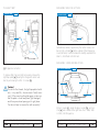
ADJUSTING THE ALIGNMENT OF THE MOVIELITE
MASK
This operation is performed by the MOVIECAM Maintenance Centre or Rental House only.
ADJUSTING THE BRIGHTNESS OF THE MOVIELITE
FRAMES
The brightness of all displayed lines on both MOVIELITE
Modules can be continuously adjusted by turning the
DIMMER knobs. When turning the knob counter-clockwise, the brightness will diminish until it is no longer visible
in the Viewfinder. Turning the knob all the way clockwise will set the MOVIELITE outlines of their maximum
brightness.
ACCESSORY CONNECTOR
On top of the Mk2 VIEWFINDER there is a 9 pin connector for the two accessories Readout Unit and Remote
Control Box. Remove the small cover plate that protects
the connector by unscrewing the 5 mm screws with an
S4 Allen key and attach the accessory.
ACCESSORY CONNECTOR
fig.3/7
connector
gauged
borehole
threated
socket
The brightness of the frame line illumination is independent from the brightness adjustment of the camera
displays.
▲
Notice
• Be aware that the brightness of the luminous red
frames my affect the colour rendition of the video
assist system.
• MOVIELITE modules cannot be mounted on the
100% Video Only Viewfinder
• On top of the MOVIELITE Modules, a shoe for
accessories is provided.
3 – THE MOVIECAM ACCESSORIES
60
MOVIECAM COMPACT Mk2
3 – THE MOVIECAM ACCESSORIES
04/2007
04/2007
MOVIECAM COMPACT Mk2
61
THE Mk2 READOUT UNIT
MOUNTING THE Mk2 READOUT UNIT
Although the Mk2 READOUT Unit is not a component of
the viewfinder system, its mounting is only possible on
top of an Mk2 Viewfinder.
After having unscrewed the 5 mm screw (S4 Allen Key)
and removed the cover from the top of the Mk2 Viewfinder, place the Mk2 Readout Unit on the Viewfinder
and fix it firmly by tightening the screw. Care should be
taken that the pin and the connector engage easily. By
placing the S4 Allen Key in the access holes, the Mk2
Viewfinder can be removed or fixed to the camera without having to remove the Mk2 Readout Unit first.
The READOUT Unit is powered directly from the camera, through the Mk2 VIEWFINDER. The digital displays
are easily readable from both camera sides. Their
brightness can be adjusted with a dimmer. The figures
glow whenever proper voltage is connected; the red
diode BAT lights up in case of a substantial voltage
drop (<20.5 V) and fades again when the camera is
sufficiently powered. The frame speed, e.g. 24 fps, is
displayed when switching on the camera. In case the
actual frame speed of the camera differs from the preset
speed, the red diode sync lights up; this diode remains
also lit as long as the camera runs up to speed.
The last indicated footage remains stored even when
the camera is disconnected. Footage information is
stored on the camera’s mainboard. When the camera is
plugged in, reset the footage counter to 0 by pushing
the reset button at least for 3 sec. By pushing briefly, the
preset unit of measurement – “f” for feet, “m” for meter
– is displayed. To change measure unit (m/ft), contact
your Rental House.
3 – THE MOVIECAM ACCESSORIES
62
MOVIECAM COMPACT Mk2
MOUNTING THE READOUT UNIT
threaded
socket
fig.3/8
gauged
borehole
connector
3 – THE MOVIECAM ACCESSORIES
04/2007
04/2007
MOVIECAM COMPACT Mk2
63
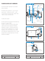
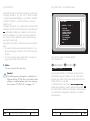
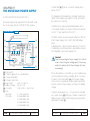
FUNCTIONS OF THE Mk2 READOUT UNIT
THE READOUT UNIT LEFT SIDE
On the Mk2 Readout Unit, the dimmer (knob) and the
reset button are located on the right side.
THE READOUT UNIT
fig.3/9
fig.3/11
fps display
sync LED
exposed
film length
display
bat LED
dimmer
reset button
The FPS displays either show the actual frame rate or
other info – please consult the related list of messages
in chapter 11 on page 205 dedicated to the FPS displays.
On the right side only, a further display also shows the
exposed film length.
The LEDS either glow red [●] or are off [●].
On both sides of the Mk2 Readout Unit, the FPS display, the Exposed Film Length display as well as a RUN
LED and a BAT LED are provided.
THE READOUT UNIT RIGHT SIDE
fig.3/10
sync LED
fps display
bat LED
exposed
film length
display
SYNC LED
● while the camera is in STAND-BY status or when
the camera is not powered
● camera is not running at the preset frame rate or
while the camera is running up or running down. It
also glows red while the camera is NOT IN SYNC
BAT LED
● while the camera is in STAND-BY status or when
the camera is not powered
● when the battery supplies less than e.g. 20.5 V
When pushing the RESET button for less than three
seconds, counter mode is displayed: “f” for feet, “m” for
meter. When pushing the RESET button for more than
three seconds, the exposed film counter is reset and the
display shows 0000 .
3 – THE MOVIECAM ACCESSORIES
64
MOVIECAM COMPACT Mk2
3 – THE MOVIECAM ACCESSORIES
04/2007
04/2007
MOVIECAM COMPACT Mk2
65
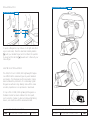
REMOTE CONTROL BOX
CONNECTING THE REMOTE CONTROL BOX
fig.3/13
on the 100% video only viewfinder
Similar to the Mk2 Readout Unit, the small connector of
the Remote Control Box is attached to the MK2 Viewfinder or to the Mk2 100% VIDEO ONLY VIEWFINDER
with one 5 mm hex screw.
▲
Remark
You cannot use the Remote Control Box when the
Mk2 Readout Unit is mounted on the Mk2 camera.
CONNECTING THE REMOTE CONTROL BOX
fig.3/12
on the viewfinder
3 – THE MOVIECAM ACCESSORIES
66
MOVIECAM COMPACT Mk2
3 – THE MOVIECAM ACCESSORIES
04/2007
04/2007
MOVIECAM COMPACT Mk2
67
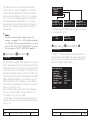
When connected to the MOVIECAM COMPACT Mk2,
the Remote Control Box works as both on/off switch
and “remote” Readout Unit. You can read exposed
footage, frame rate, battery condition, sync speed and
warning signs up to a distance of 10 m. As long as the
Remote Control Box is connected to the ready-to-shoot
camera (Stand-By status), the footage counter lights up.
Functions of the two buttons:
CHECK button In Stand-By mode
Pressed briefly
Pressed for 2 seconds
Shows the preset FPS 1 or
a warning message
RESET button
Pressed briefly
Current Unit of
measurement
is displayed
THE REMOTE CONTROL BOX fig.3/14
frame rate
check button
reset button
▲
sync speed
on/off button
3 – THE MOVIECAM ACCESSORIES
68
MOVIECAM COMPACT Mk2
Counter is reset to [0]
RESET button
While camera is running
Pressed briefly
Pressed for 2 seconds
Trigger a preset ramp
FPS 1 > FPS 2 or
FPS 2 > FPS 1
battery
condition
exposed
footage
In Stand-By mode
Pressed for 2 seconds
Remark
While the camera is running, pressing the RESET button will trigger a preset ramp.
Only with the COMPACT Mk2, it is now possible to
reverse the ramp by pressing again the RESET button
– without stopping the camera.
3 – THE MOVIECAM ACCESSORIES
04/2007
04/2007
MOVIECAM COMPACT Mk2
69
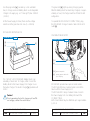
VIEWFINDER LEVELLING ROD
MOUNTING THE VIEWFINDER LEVELLING ROD fig.3/16
A Viewfinder Support Levelling Rod may be attached
to the Viewfinder Extensions. This Rod is attached by
sliding the sprung loaded dovetail into the holder. To
remove it, press the spring lever. The support is clamped
to the head and its length is adjustable.
spring lever
Caution!
When working with the Levelling Rod, the Rotation Friction Adjustment must be loose (see page
37 fig. 2/6)!
dovetail holder
MOUNTING THE VIEWFINDER LEVELLING ROD fig.3/15
3 – THE MOVIECAM ACCESSORIES
70
MOVIECAM COMPACT Mk2
3 – THE MOVIECAM ACCESSORIES
04/2007
04/2007
MOVIECAM COMPACT Mk2
71
THE MOVIECAM VIDEO ASSISTS’ COMPONENTS
Important notes and safety specifications
• Turn OFF the Video Assist immediately in case of malfunction!
• Do not use in the presence of flammable gas!
• Do not disassemble!
• Use only MOVIECAM cables!
• Use MOVIECAM Mk2 Video Assist components only
with MOVIECAM Mk2 Cameras and only as described in this manual!
• Assembly and initial installation should be carried out
only by persons who are familiar with the equipment!
• Remove all cables before transport or servicing!
• Repairs should be carried out only by authorized
MOVIECAM Maintenance Centres!
• Use only original MOVIECAM replacement parts and
accessories!
• Check all operations on the corresponding monitor!
• In wet weather the normal safety precautions for handling electrical equipment should be taken!
• Keep the equipment dry and free of salt, sand or dust!
• Keep optical surfaces clean!
• Do not remove or turn any screws which are secured
with paint!
• Turn the camera MAIN switch OFF before mounting
or removing electric components or when connecting
or removing the power supply!
• Keep equipment away from strong magnetic fields!
• Avoid sudden changes in temperature!
• Never feed power onto sync or video lines!
4 – THE Mk2 VIDEO ASSIST SYSTEM
72
MOVIECAM COMPACT Mk2
▲
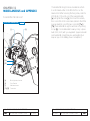
CHAPTER 4
THE Mk2 VIDEO ASSIST SYSTEM
Preliminary Remark
Even though the MOVIECAM Mk2 VIDEO ASSIST
COMPONENTS are similar to the one provided by
ARRI for the ARERICAM cameras, these MOVIECAM
COMPONENTS are not compatible with the ARRI
ones.
Nevertheless On Board Video Monitors provided by
MOVIECAM as well as ARRI may be used with the
MOVIECAM Mk2 VIDEO ASSIST – presuming that
the connection is made adequately.
The MOVIECAM Video Assist System offers more
than just a video tap picture. As well as the viewfinder picture, most of the camera status can be
displayed on the monitor and/or recorded on tape
or hard disc. This information is useful for further steps
in production and post-production. By means of a
sophisticated, but intuitive and user-friendly menu,
several options can be selected. For example, flicker
compensation, a picture storage capability and a
frame line generator are provided.
To access all the different options, only a single dial
needs to be operated. However, the main parameters can be changed straightaway by pushing dedicated buttons.
4 – THE Mk2 VIDEO ASSIST SYSTEM
04/2007
04/2007
MOVIECAM COMPACT Mk2
73
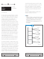
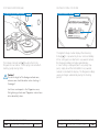
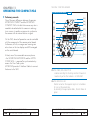
THE MOVIECAM VIDEO ASSIST’S COMPONENTS
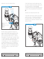
The MOVIECAM Mk2 Viewfinder has a dedicated
Video Assist system.
MOVIECAM also provides two 2”, colour on board
video monitors – one PAL and one NTSC – which
can be mounted on the MOVIECAM COMPACT Mk2
camera, by means of articulated arms.
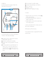
VIDEO ASSIST – FRONT fig.4/1
white balance
button
video signal
BNC mode
button
white balance
mode leds
signal
leds
video assist
mounting screws
on/off/
check/
hide menu
switch/led
THE Mk2 VIDEO ASSIST
The Mk2 Video Assist is equipped with lenses that cover
the Super 35 acquisition format.
Therefore no mechanical change to the Video Assist
needs to be done when changing the format from
Standard 35 to Super 35. Please be aware that not
all monitors show the extended field of a S35 image.
Depending on the video standard used, each Video
Assist component is labelled either PAL or NTSC. Please
be aware that only components working on the same
standard are compatible.
on board monitor
connector
menu/store/
MGC dial
manual gain
control button/led
CCD
adjustments
cover
retaining
screws
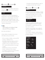
fig.4/2
VIDEO ASSIST – TOP
accessory shoe
menu/store/
MGC dial
VIDEO ASSIST – RIGHT
on board monitor
connector
fig.4/3
on board
monitor connector
video assist
iris control dial
4 – THE Mk2 VIDEO ASSIST SYSTEM
74
MOVIECAM COMPACT Mk2
4 – THE Mk2 VIDEO ASSIST SYSTEM
04/2007
04/2007
MOVIECAM COMPACT Mk2
75
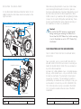
MOUNTING THE VIDEO ASSIST
On the Mk2 VIEWFINDER and the Mk2 VIDEO ONLY
VIEWFINDER, the Mk2 Video Assist is mounted on the
right hand side.
ATTACHMENT FOR VIDEO ASSIST ON VIDEO ONLY VIEWFINDER fig.4/4
mounting screw
threaded
boreholes
After removing the protection cover (one 4 mm screw)
and checking that both parts (connectors, glass surfaces) are absolutely free of dust and fingerprints, mount
the Mk2 Video Assist to the Mk2 Viewfinder or Mk2
100% Video Only Viewfinder. While tightening the two
screws, the connectors fit together automatically. Therefore be sure that the Mk2 Video Assist sits securely on
the Viewfinder or Video Only Viewfinder.
Caution!
Be sure that the Mk2 camera is not powered
during mounting or removing the Video Assist.
Do not slant the Mk2 Video Assist while mounting
it on the Viewfinder or on the 100% Video Only
Viewfinder!
THE CONNECTORS AND THE LED INDICATORS
THE CONNECTORS FOR THE ON BOARD VIDEO
MONITOR
ATTACHMENT FOR VIDEO ASSIST ON VIEWFINDER
fig.4/5
Two connectors, one to connect a MOVIECAM ON
BOARD VIDEO MONITOR and one for connecting an
ARRI ON BOARD VIDEO MONITOR, are located on
top of the Mk2 Viewfinder.
By means of a little rotatable cover – mounted adequately e.g. at the rental house – only one of both connectors will be reachable. This precaution should avoid
any wrong connection. The accessible connector is
protected by an aluminium cap. By lifting this cap, you
will be able to connect only one ON BOARD MONITOR. Other monitors can be connected to the VIDEO
OUT connector located at the rear side of the Mk2
Viewfinder.
threaded boreholes
mounting screws
4 – THE Mk2 VIDEO ASSIST SYSTEM
76
MOVIECAM COMPACT Mk2
4 – THE Mk2 VIDEO ASSIST SYSTEM
04/2007
04/2007
MOVIECAM COMPACT Mk2
77
In case, the little protection has to be rotate, first switch
the COMPACT Mk2 camera off, then remove the two
little screws [a] and [b], raise the cover, rotate it and
replace it carefully on the camera. Then secure it by
tightening the two screws.
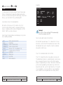
THE FURTHER CONNECTORS
On the left side of the Mk2 Video Assist, four connectors
and one LED are located.
The LED lights up green when an external video sync
signal is successfully fed to the Video Assist.
VIDEO ASSIST CONNECTORS FOR ON BOARD MONITOR fig.4/6
[a]
[a]
[b]
CONNECTORS OF THE VIDEO ASSIST
fig.4/9
[b]
ext. sync led
video out without data or C
MOVIECAM connector
ext. sync in
ARRI connector
s-video out
(Y/C)
video out
with data or Y
VIDEO ASSIST CONNECTOR FOR ARRI ON BOARD MONITOR fig.4/7
+12 V (1.3 A continous
1.5 A peak, PIN 4
signal shield, PIN 2
▲
composite video,
PIN 3
GND, PIN 1
VIDEO ASSIST CONNECTOR FOR MOVIECAM ON BOARD MONITOR fig.4/8
+12 Volt, PIN 3
GND, PIN 4
NC, PIN 2
Video, PIN 1
4 – THE Mk2 VIDEO ASSIST SYSTEM
78
MOVIECAM COMPACT Mk2
Notice
When attaching a cable to one of the connectors,
be sure not to bend it. Providing a strain relief will do
fine.
In order to avoid interference, be sure not to install
the video cable close to electric drives, e.g. lens
motors.
Be sure the cable has enough slack to accommodate
the full range of camera movements, either if it is
operated manually or by a remote head! It is recommended to use of Y/C cables, which are delivered
with the unit, for even better image quality.
4 – THE Mk2 VIDEO ASSIST SYSTEM
04/2007
04/2007
MOVIECAM COMPACT Mk2
79
THE VIDEO OUT SIGNAL (BNC CONNECTORS)
THE S-VIDEO SIGNAL
By means of the (video signal) BNC MODE button – see
page 75 fig. 4 /1 – you may select the kind of video
signal you would like to output. Three options are available and the selected choice is indicated by an LED.
Provided that the monitor has a S-Video connector, using
the S-Video signal instead of the composite one will provide an even better video picture. S-Video cables allow
connection up to about 3 m/10 ft.
video with data on screen Y= luminance signal
video without data
C= chrominance signal
composite video with on-screen data
COMP. composite video
without on-screen data
Y portion of the video,
with on-screen data
Y/C.
C portion of the video signal,
with on-screen data
Y portion of the video,
without on-screen data
Y/C.
C portion of the video signal,
without on-screen data
VIDEO CABLE CONNECTIONS
video assist
fig.4/11
video monitor
video recorder
S-Video cable
A
B
VIDEO CONNECTIONS
A
For longer distance more resistant BNC cables could be
used.
B
A further possibility is to use two BNC cables and one
S-Video adapter cable: Red = C, White = Y
A
B
VIDEO CABLE CONNECTIONS
A
video assist
fig.4/12
BNC cable
white
BNC cable
red
video monitor
video recorder
B
S-Video adapter cable
▲
Notice
If you would like the video picture in Black & White,
please select either Y/C
or
and connect
the video cable to ”A” output.
This configuration will provide the best possible
result when the distance between the MOVIECAM
COMPACT Mk2 and the monitor(s) is (are) longer
than 10 m/33 ft.
Standard BNC connection:
VIDEO CABLE CONNECTIONS fig.4/10
video assist
BNC cable
video monitor
video recorder
4 – THE Mk2 VIDEO ASSIST SYSTEM
80
MOVIECAM COMPACT Mk2
Caution!
Make sure that the length of both BNC cables is
similar.
4 – THE Mk2 VIDEO ASSIST SYSTEM
04/2007
04/2007
MOVIECAM COMPACT Mk2
81
▲
Notice
If video pictures with and without inserted data are
needed simultaneously, e.g. viewing on monitor without data while recording on hard disc with the data
inserted, two separated connections must be installed.
VIDEO CABLE CONNECTIONS
video assist
MOVIECAM A
video assist
MOVIECAM B
video assist
fig.4/13
BNC cable 1
BNC cable 2
video monitor
no visible data
video monitor
inserted data
video monitor
A and B mixed
Caution!
A standard S-Video connector has no
fixture similar to a BNC one. Therefore, the
S-Video connected cable must be secured in order
not to slip accidentally out of the connector.
THE EXT. SYNC SIGNAL
4 – THE Mk2 VIDEO ASSIST SYSTEM
MOVIECAM COMPACT Mk2
video out (BNC)
video mixing
console
BNC cable B
(hard disc)
recorder
monitor
video A
monitor
video B
Notice
The synchronization provided by connecting a VIDEO
OUT connector to an EXT SYNC IN connector only
affects the video signal. If a synchronization of a
MOVIECAM Camera itself is required, please see the
dedicated explanations later in this chapter under “On
Screen Display menu” (Sub-menu CAMERA SYNCED),
page 100 or consult chapter 11 – Camera synchronization page 208.
THE MECHANICAL ADJUSTMENTS OF THE CCD
▲
When video images are provided from several MOVIECAM Mk2 Video Assists, e.g. when cameras are used
in a multiple camera application and the video images
must be mixed together, they should be synchronized.
To do so, a BNC cable must connect the Mk2 Video
Assist e.g. of the camera A with the one of the camera
B. The cable is plugged in a VIDEO OUT connector
on camera A and connected to the EXT SYNC IN connector on Camera B. In the Video Config. menu, EXT
SYNC (not TC) has to be selected.
82
BNC cable A
ext sync in (BNC)
▲
(hard disc)
recorder
fig.4/14
VIDEO CABLE CONNECTIONS
Notice
This operation should be done by the rental house
before delivering equipment. Once set, these adjustments should not move, but if adjustment does become
necessary, the focus puller can improve the alignment
and the focus of the video image. Adjustments are
made with a 1.5 mm metric hex wrench.
Caution!
Never use force.
4 – THE Mk2 VIDEO ASSIST SYSTEM
04/2007
04/2007
MOVIECAM COMPACT Mk2
83
CCD ADJUSTMENT
fig.4/15
S2
S1
THE ELECTRONIC ADJUSTMENTS OF THE VIDEO
ASSIST CAMERA
▲
In order to access to the controls, first the cover must be
removed from the Mk2 Video Assist by unscrewing two
screws with a 1.5 mm metric hex wrench.
Remark
The electronic adjustments can only be carried out
when the camera is ready to shoot (STAND-BY status)
– no error message must be displayed.
THE BNC MODE BUTTON AND THE THREE LEDS
See page 80 for explanations.
CCD adjustments
cover retaining screws
S3
THE WHITE BALANCE BUTTON AND THE FOUR LEDS
S4
Three screws allow the fine positioning of the CCD and
one screw (S4) moves it in and out to obtain the best
possible focus.
Screw S1 moves the video image on the monitor horizontally.
Screw S2 and S3 rotate the image around a point
which is located in the middle of the left side respectively right side of the image. To shift the image vertically,
you will have to alternate the adjustments of both screws
S2 and S3 to obtain the desired position.
VIDEO ASSIST IMAGE ADJUSTMENT
fig.4/16
S1
video
image
of the
groundglass
S2
S3
S1 adjustment
image on the
video monitor
4 – THE Mk2 VIDEO ASSIST SYSTEM
84
MOVIECAM COMPACT Mk2
By pushing the WHITE BAL button several times, you
cycle through the four options to adapt the Mk2 Video
Assists’ CCD to the lighting conditions (colour temperature) and the photographic conditions (use of compensation or coloured filter).
1. When shooting in daylight condition (about 5.600°K
natural daylight, HMI or blue filtered tungsten luminaries) and when no compensation filter is used, you
may obtain a good result in selecting OUTDOOR.
If a Wratten 85 or similar filter is used to compensate daylight because the film used is balanced for
3.200°K, selecting INDOOR will produce a good
result.
2. When shooting in interior conditions (about 3.200°K
light or studio halogen luminaries) and when no
coloured filter is used, you should obtain a good
result in selecting INDOOR.
3. By selecting AUTO, the electronics will adapt automatically the CCD in order to obtain a ”natural”
rendition of the scene.
4 – THE Mk2 VIDEO ASSIST SYSTEM
04/2007
04/2007
MOVIECAM COMPACT Mk2
85
▲
Notice
When using the AUTO mode for adjusting the white
balance, one should be aware that the colour of the
MOVIELITE will affect the result. So, the more ”red
light” that surrounds the frame, the more cyan the video
picture will appear.
THE VIDEO LENS IRIS CONTROL
To control the brightness of the video image, two parameters can be changed on the Video Assist: the video
gain setting and the video lens iris adjustment.
The lens of each Video Assist is equipped with an iris to
control the amount of light falling on the CCD. However, because of the very effective AGC (Automatic Gain
Control), which works over many f stops, it is suggested
to normally leave the Video iris fully open.
THE MGC (MANUAL GAIN CONTROL) BUTTON
AND THE LED
The gain is the electronic amplification of the video
signal. Higher gain provides a brighter image but the
video picture quality deteriorates with increased video
‘noise’. That may bother the Director and other on the
set.
4 – THE Mk2 VIDEO ASSIST SYSTEM
86
MOVIECAM COMPACT Mk2
▲
4. A better result, especially when shooting in mixed
lighting situation, will be obtained by using the
MANUAL white balance adaptation. By using this
option, you are able to change the white balance
settings in the menu. For more details see the WB/
GAIN description on page 94.
Because of this it is preferable to first set the iris of the
Video Assist lens wide open before increasing the gain
manually.
Since the Automatic Gain Control (AGC) averages the
image brightness, in some lighting situations (strong
backlight, for instance) Manual Gain Control (MGC)
is yield a better video image. Push the MGC button to
toggle between Manual Gain Control (MGC LED ON)
and Automatic Gain Control (MGC LED OFF). When
MGC is ON, rotate (do not push it) the dial clockwise
to increase or counter-clockwise to decrease the video
gain.
Notice
If the video image looks too dark or if there is too
much electronic noise,
• first check the iris setting of the lens on the camera;
it should be set for the correct film exposure.
• secondly check the iris setting of the Video Assist;
it must be wide open.
• now check if the gain control is set on AGC.
If the video image is still too dark,
• it is possible that the video exposure time is set to
FILM (see submenu VIDEO CONFIG/EXPOS.TIME
on page 97), the shutter opening is very small
(e.g. 22.5°) or a high frame rate (e.g. 50 fps) is
selected.
• it is possible that a strong light is coming directly
into the lens (e.g. strong backlight from a window
or from the sun during sunset).
In these cases, switch to MGC (Manual Gain Control) and raise the gain a bit.
4 – THE Mk2 VIDEO ASSIST SYSTEM
04/2007
04/2007
MOVIECAM COMPACT Mk2
87
▲
ON/OFF/CHECK/HIDE MENU SWITCH AND LED
Before switching ON the video system, first make sure
that the camera is powered. Now move the ON/OFF/
CHECK/HIDE MENU switch on the Video Assist to the
ON position. The ON LED will light up.
CHECK OR HIDE THE MENU
Notice
1. When the navigation function has not been
activated and the Manual Gain Control (MGC)
is ON, the dial serves to increase (by turning it
clockwise) or decrease (by turning it counterclockwise) the gain level.
2. As soon as the On Screen Display (OSD) is
activated (by having pushed the dial for about
3 sec.), there will always be data to all outputs in
order to be able to use the menu.
To display a summary of all options chosen from the
menu while the OSD (On Screen Display) is not visible,
push the ON/OFF/CHECK/HIDE MENU switch all
the way down to CHECK/HIDE MENU. The OSD will
automatically fade out after a few sec. To hide the OSD
menu, push the ON/OFF/CHECK/HIDE MENU switch
all the way down to CHECK/HIDE MENU. This is
useful if the image needs to be checked while selecting
options or making adjustments in the On Screen menu.
See the configuration summary on page 114.
While the OSD menu is ON, no changes of the settings
by means of the buttons are possible. The data in the
inserted windows are not updated.
THE MENU/STORE DIAL
THE VIDEO ASSIST ON SCREEN DISPLAY (OSD)
In order to navigate through the elaborate menu of the
Video Assist functions, only handling one single userfriendly dial is needed. The dial can be pushed briefly
or longer (about 3 sec.) and turned to the left and to
the right. By means of these four operations, each one
of the video functions can be selected, activated, and
stored.
Beside the ”normal video tap” function of the MOVIECAM Mk2 Video Assist System, many features are offered to the users in order to facilitate not only the work
on the set, but also the processes in post production
houses.
In order to adjust the various settings, first you have to
make yourself familiar with the easy to use navigation
system. To navigate, only the MENU/STORE dial is
used; it is either pushed or turned.
VIDEO ASSIST MENU/STORE DIAL
fig.4/17
MGC
+
▲
MGC
–
Caution!
By pushing the dial while the OSD is not visible,
the actual image will be stored in the Video Assist
memory, deleting the previous stored image.
Notice
No OSD is available while the camera is
RUNNING.
MENU/STORE
4 – THE Mk2 VIDEO ASSIST SYSTEM
88
MOVIECAM COMPACT Mk2
4 – THE Mk2 VIDEO ASSIST SYSTEM
04/2007
04/2007
MOVIECAM COMPACT Mk2
89
By pushing the dial briefly while the OSD is
visible, you will activate the function or option marked by the menu-cursor –> .
By pushing the dial for about 3 sec. – this
can be done at any time – you will either
open or close the On Screen Menu. While
closing the OSD, the latest displayed options
are automatically activated.
By turning the dial, you will either:
• move the menu-cursor –> ,
• move the character-cursor X ,
• change the option between e.g. ON , and
OFF , SMALL , and LARGE , etc.
• adjust a value, e.g. from 48 to 12 or
to 54 ,
• position a line, a frame or a window on
the display.
On each displayed level, the option EXIT, is provided.
By selecting exit and pushing the dial shortly, you will
climb the program to the next superior level (D). When
you push more than 3 sec., the latest changes will be
activated and the OSD will fade out.
(A)
–> MENU
MENU
MENU
MENU
MENU
(B)
1
2
3
4
5
SET 1 = OFF
–> SET 2 = HIGH
SET 3 = 48
EXIT
1
2
3
4
EXIT
EXIT
(C)
OPTION
OPTION
–> OPTION
OPTION
(D)
SET 1 = ON
OFF
SET 2 = LOW
HIGH
SET 3 = XX
EXIT
(xx = 0 to 99)
THE MENU STRUCTURE
THE CURSOR
The menu is structured dynamically, this means that the
several related levels (Sub-menus) will appear automatically when a higher menu level is selected. The first level
– the Main Menu list (A) – will appear when the dial is
pushed for about 3 sec.
The cursor –> will face one of the Sub-menu titles. By
turning the dial, the cursor will scroll all lines. Each of
these Sub-menus offers different options. By pushing the
dial, the selected Sub-menu will show its list of options
(B). Each option offers the possibility to select individually several settings (C) listed on the third level.
While turning the dial, the cursor –> will move from
line to line. As soon as the desired option is reached, a
short push on the dial will select it. Remember, if the dial
is pushed longer than 3 sec., the OSD will fade out.
When an option is selected, all its functions and settings
will appear in a list. Now a function or a setting can be
selected by turning the dial.
4 – THE Mk2 VIDEO ASSIST SYSTEM
90
MOVIECAM COMPACT Mk2
When the cursor –> shows a function, a push on the
dial will activate this function and the setting can be
chosen again by turning the dial. While pushing the
dial briefly, the selected setting is confirmed.
The navigation in the menu is very simple and, because
of its logical structure, can be learned in a few minutes.
4 – THE Mk2 VIDEO ASSIST SYSTEM
04/2007
04/2007
MOVIECAM COMPACT Mk2
91
THE FIRST LEVEL – THE MAIN MENU
THE SETTINGS
By turning the dial, the following changes can be done:
Changing of options: e.g. ON > OFF; LIGHT > DARK
Cycling several preset settings: e.g. SMALL > MEDIUM
> LARGE; DEFAULT > CONFIG USER1 > CONFIG
USER 2 > etc.
Changing of position: e.g. vertical shift, horizontal shift
Entering text: while turning the dial, the character-cursor
X will mutate to letters and numbers. As soon as the
desired character is On Screen, it will be saved and
the cursor will move left to the next possible place by
pushing the dial shortly.
Leaving the OSD menu: There are two ways to exit the
menu:
1. To leave the actual menu level and to return to one
menu level higher, move the cursor to EXIT and push
the dial.
2. To close all menus and to leave the On Screen Display, push the dial for about 3 sec.
▲
Notice
The menu can be left at any time.
)
WB/GAIN
VIDEO CONFIG
FORMAT MARKING
COMPARE/STORE
TEXT INSERTER
VITC/WHITELINE
CONFIG SET
EXIT
THE SECOND AND FURTHER LEVELS –
THE SUB-MENUS
–> CONFIG = 1 (USR1
4 – THE Mk2 VIDEO ASSIST SYSTEM
MOVIECAM COMPACT Mk2
–> CONFIG = 1 (USR1
MAIN MENU
Caution!
The following menu description is related to the
Software Version V2.06. To be sure that the latest
software is installed, please check it by selecting
the Sub-menu CONFIG SET. See page 113.
92
MAIN MENU
CONFIG
)
By pushing the MENU/STORE dial for about 3 sec.,
the first menu level will appear. On top of the menu
window, the name of the actual displayed level (here
MAIN MENU) is indicated.
In the first line the cursor shows CONFIG = 1 (USR1 ) .
Beside the possibility to use the default configuration = 0 ,
the MAIN MENU offers the possibility to select between
six customised configurations available in the Video
Assist memory.
4 – THE Mk2 VIDEO ASSIST SYSTEM
04/2007
04/2007
MOVIECAM COMPACT Mk2
93
The settings of these six configurations (WB/GAIN,
VIDEO CONFIG, FORMAT MARKING, COMPARE/
STORE, TEXT INSERTER and VITC/WHITE LINE) will
be done with the Sub-menu CONFIG SET – see page
113. There, the six individually preset configurations
will automatically be numbered from 1 to 6 and you
may also add a name into the brackets. The memory
will save the configurations even when the camera is
not powered.
▲
Notice
To check a summary of the settings saved in the
memory – see page 115 – of the selected configuration, close the OSD by pushing the dial for 3 sec. and
push the ON/OFF/CHECK/HIDE MENU switch all
the way down to CHECK/HIDE MENU position.
MAIN MENU
WB/GAIN
–> WB/GAIN
While activating the WB/GAIN Sub-menu, you will be
able to adjust manually the colour balance and the gain
of the Video Assist. For ”normal use”, the selection of the
colour balance as well as the gain can be done using
the WHITE BAL button as well as the MGC button. The
OSD menu allows to make fine adjustments of all preset
settings beside the default one. By selecting e.g. IND.
RED in the WB=INDOOR Sub-menu, you will be able
to alter the factory presetting by reducing or raising the
value in a range of 0 to 99.
If the individual factory setting of the colour saturation is
e.g. 52, you will be able to change it from 52 to 0
(–52 steps) or 52 to 99 (+47 steps).
In AUTOMATIC, the electronics will analyse the light
entering the camera and offer a neutral rendering of the
colours, e.g.
4 – THE Mk2 VIDEO ASSIST SYSTEM
94
MOVIECAM COMPACT Mk2
–> WB = AUTOMATIC
INDOOR
OUTDOOR
MANUAL
▼
▼
WB = MANUAL
MAN. RED = 50 + 00
MAN. BLUE = 50 + 00
WB = OUTDOOR
OUT. RED = 38 + 00
OUT. BLUE = 51 + 00
▼
WB = INDOOR
IND. RED = 52 + 00
IND. BLUE = 43 + 00
In the same way, the MANUAL GAIN can be adjusted
in a range from 0 to 99.
GAIN = AGC
= MGC
GAIN = MGC
MANUAL GAIN = 0
MAIN MENU
VIDEO CONFIG
–> VIDEO CONFIG
The VIDEO CONFIG Sub-menu allows the selection of
several options related either to the video image rendering, to the signal provided by the Video Assist and to
the synchronization of the camera.
MENU VIDEO CONFIG
–> FLICKERFREE
EXPOS. TIME
LINE INTERP.
Y/C (SVHS) DATA
MINI MON. DATA
VID SYNC
CAMERA SYNCED
PHASE 0 – 356
=
=
=
=
=
=
=
=
ON
FILM
ON
ON
OFF
EXT (NOT TC)
OFF
0.0
EXIT
4 – THE Mk2 VIDEO ASSIST SYSTEM
04/2007
04/2007
MOVIECAM COMPACT Mk2
95
MAIN MENU
FLICKERFREE
VIDEO CONFIG
MAIN MENU
EXPOS. TIME
–> EXPOS. TIME = FIXED
= FILM
–> FLICKERFREE = ON
= OFF
The flicker effect on video monitor results from the difference between the frame rate of the film camera and the
one of the Video Assist. In selecting the option ON, the
flicker will be fully eliminated. This is achieved by storing the digital image into a video frame storage while
the mirror is in the viewing position and to display this
picture in the correct timing of the video system. The
FLICKERFREE option works when the frame rate of the
Mk2 is set faster than 1 fps.
▲
Notice
The storage of the digital image causes a slight
delay, which is not desirable in some crucial time
conditions, e.g. motion control or shooting singers or
musicians with play-back sound. Therefore it is possible to select the FLICKERFREE = OFF option.This will
eliminate the delay at expense of the return of flicker.
Caution!
The time-code information such as time-code, user
bits, VITC and WHITELINE is not valid if FLICKERFREE = OFF is selected.
4 – THE Mk2 VIDEO ASSIST SYSTEM
96
MOVIECAM COMPACT Mk2
VIDEO CONFIG
When the mode FIXED is selected, the exposure time
of the CCD will automatically be calculated accordingly to the formula 1/(fps x 2) regardless whether the
video standard is PAL or NTSC. The shutter opening is
considered 180° fixed. Example: the fps rate is 24; the
exposure time will be 1/(24 x 2) = 1/48 Sec.
Caution!
This calculation is based on the 180° shutter
opening; even though the shutter could have been
modified manually!
In selecting the option FILM, the Video Assist electronics
calculates the film exposure time while the film camera
is in STAND BY status. In toggling between FIXED and
FILM exposure time, you will see a difference in the
image brightness.
A practical use of the option FILM is the ”video visualization” of motion blur and stroboscopic effect that will
be recorded on film.
4 – THE Mk2 VIDEO ASSIST SYSTEM
04/2007
04/2007
MOVIECAM COMPACT Mk2
97
▲
MAIN MENU
LINE INTERP.
VIDEO CONFIG
–> LINE INTERP. = ON
= OFF
In order to enhance the quality of the Video Assist picture, you may virtually double the vertical resolution in
adding so called interpolated lines.
MAIN MENU
Y/C (S-VHS) DATA
VIDEO CONFIG
–> Y/C (SVHS) DATA = ON
= OFF
By selecting ON, the video image supplied by the Y/C
(S-VHS) connector will include the data information.
MAIN MENU
MINI MON. DATA
VIDEO CONFIG
–> MINI MON. DATA = ON
= OFF
By selecting ON, the video image supplied by the On
Board Monitor connector will include the data information.
MAIN MENU
VID SYNC
VIDEO CONFIG
–> VID SYNC = EXT (NOT TC)
V= TC
Notice
Without selecting CAMERA SYNCED ON (VID,
TC), this synchronization is only related to the Video
Assist, not to the one of the camera! Therefore, the
external sync signal must be fed in the Video Assist
connector and not in the Mk2 camera connector.
While selecting EXT, the Video Assist will be synchronized with an external signal e.g. video or clock fed
in the EXT. SYNC IN BNC connector. The green LED
located next to the connector will light up to monitor that
the fed synchronization signal is OK.
If EXT is selected, either a standard video composite or
a TTL (0 and 5 V) signal should be fed in the EXT SYNC
IN connector.
The range of frequencies is 25 or 50 Hz for the PAL
standard and 30 or 60 Hz for the NTSC standard.
A divergence smaller than ± 0.1% is tolerated. The
input impedance will automatically switch between
10 K Ω for TTL and 75 Ω for video signals.
Caution!
If no usable external signal is fed to the EXT.
SYNC IN connector, the Video Assist will run on
its own internal oscillator.
The LED next to the connector will show by lighting green if the signal is appropriate. The use of
the Pick-up Unit in connection with the Video Assist
connector is not possible.
With this menu, the reference used to synchronize the
Video Assist can be selected.
4 – THE Mk2 VIDEO ASSIST SYSTEM
98
MOVIECAM COMPACT Mk2
4 – THE Mk2 VIDEO ASSIST SYSTEM
04/2007
04/2007
MOVIECAM COMPACT Mk2
99
MAIN MENU
CAMERA SYNCED
VIDEO CONFIG
MAIN MENU
–> CAMERA SYNCED = OFF
= VID
= TC
With this Sub-menu, the synchronization reference of the
film camera can be selected.
OFF means that the references signal is provided by the
film camera’s own quartz crystal generator.
VID means that the film camera will use the video signal
for synchronization.
Selecting TC is currently not available
Caution!
TC selection is only possible when a TIME CODE
BOX is connected.
Whenever the Video Assist is switched ON, the
CAMERA SYNCED function is always set to OFF
in order to avoid wrong speed.
VIDEO CONFIG
–> PHASE 0 – 356 = 0.0
When VID is selected in the CAMERA SYNCED Submenu, the next menu level PHASE 0 – 356 allows
to adjust the phase between the external sync signal
and the film camera. By turning the dial, the phase can
be adjusted with increments of 3.6° in a range 0° to
356.4°.
4 – THE Mk2 VIDEO ASSIST SYSTEM
100
MOVIECAM COMPACT Mk2
The FORMAT MARKING Sub-menu allows to design
and insert one or two sets of frame lines – either individually or simultaneously – into the Video Assist image.
Complementary to the following already programmed
and named aspect ratios, the Sub-menu allows to design
further twelve frames which can be labelled individually.
FORMAT No.
1
2
3
4
NAME
TV 4:3
TV 16:9
1.85
2.35
ASPECT RATIO
1:1.333
1:1.777
1:1.85
1:2.35
Even with the four listed frames, their sizes, their brightness and their positions on the TV screen can be adjusted. The positioning allows precise lining up the electronic frames with the Groundglass Format Markings.
▲
MAIN MENU
PHASE 0 – 356
FORMAT MARKING
–> FORMAT MARKING
Notice
If the electronic Format Markings are not parallel to
the Groundglass Format Markings, readjust the CCD
chip with the Adjusting screws as explained on page
84. Be aware that first the Groundglass Format Markings must be positioned on the TV monitor by means
of the CCD chip adjustment before positioning the
generated frame lines. It is recommended to point the
film camera towards a bright surface and to turn OFF
the MOVIELITE so that the Format Markings on the
Groundglass are clearly visible.
4 – THE Mk2 VIDEO ASSIST SYSTEM
04/2007
04/2007
MOVIECAM COMPACT Mk2
101
Furthermore, the appearance of the surrounding area of
one of the selected frames can be adjusted accordingly
to the users needs.
–> WHITELEVEL = DARK
= MEDIUM
= BRIGHT
MENU FORMAT MARKING
FORMAT 1
= FRAME
–> FORMAT 2
=
WHITELEVEL
OUTS. AREA
1(TV 4:3
)
While WHITELEVEL is activated, the brightness of the
frame lines can be adjusted.
OFF
= DARK
= BRIGHT
CONFIG FORMAT
1
RESET FORMAT
1 = YES
MAIN MENU
MENU FORMAT MARKING
EXIT
The following explanations are valid for both FORMATs
and for all FRAMEs
MAIN MENU
MENU FORMAT MARKING
FORMAT 1
–> = FRAME 1
(TV 4:3
)
4 – THE Mk2 VIDEO ASSIST SYSTEM
MOVIECAM COMPACT Mk2
–> OUTS. AREA =
=
=
=
BLACK
DARK
BRIGHT
VIDEO
While OUTS. AREA is activated, the brightness of the
surrounding of the selected frame can be adjusted.
While selecting VIDEO, the video image will appear
accordingly to the settings bright or dark. If BLACK is
selected, the surrounding will show no video images but
only a neutral black surface.
▲
While FRAME is activated and the dial turned, all the
preset configurations related to this selected FORMAT
will appear cyclical.
OFF will appear at the end of the list; it can be activated if no frame saved under the selected FORMAT
should be inserted.
102
MAIN MENU
MENU FORMAT MARKING
Notice
This function is only available if FORMAT 1 or 2 is
activated. No darkening function is available if there
is no FORMAT Marking or if two FORMAT Markings
are switched ON.
4 – THE Mk2 VIDEO ASSIST SYSTEM
04/2007
04/2007
MOVIECAM COMPACT Mk2
103
MAIN MENU
MENU FORMAT MARKING
CONFIG FORMAT
MAIN MENU
MENU FORMAT MARKING
CONFIG FORMAT
–> RESET FORMAT = YES
= NO
= UNDO
MENU CONFIG FORMAT 1
NAME
=
1(TV 4:3
)
MOVE LINES
ALL
HORIZONTAL
–>
VERTICAL
LEFT
RIGHT
TOP
BOTTOM
While RESET FORMAT is activated, the actual frame
design can be reset to the factory default setting.
While selecting UNDO, the last changes will be deleted and the previous setting activated.
UNDO is only available when the OSD has not been
left before.
EXIT
The Sub-menu CONFIG FORMAT 1 (or 2) allows the
design and labelling of a frame.
While NAME is activated, it is possible to select the
already displayed name, to clear it and to set a new
one.
A cursor will indicate where characters can be placed.
While ALL is activated, turning the dial will either increase or decrease the size of the frame.
While HORIZONTAL or VERTICAL is activated, the
whole frame can be positioned.
MAIN MENU
COMPARE/STORE
–> COMPARE/STORE
The Video Assist allows to store one image in its own
memory (the stored image) and to compare it with the
image currently captured (the live image). The stored
image will remain in the memory as long as the Video
Assist is powered and obviously as long as it is not
replaced by a new image.
MENU COMPARE STORE
MAIN MENU
MENU FORMAT MARKING
CONFIG FORMAT
FORMAT 1
–> = FRAME 1
–> VIEW MODE
=
LIVE
STORE IMAGE
CLEAR IMAGE
EXIT
(TV 4:3
)
Beside the possibility to change the size and position of
a frame, each line (LEFT, RIGHT, TOP, BOTTOM) can
be positioned individually. How to write a CONFIG
NAME is described on page 92.
4 – THE Mk2 VIDEO ASSIST SYSTEM
104
MOVIECAM COMPACT Mk2
4 – THE Mk2 VIDEO ASSIST SYSTEM
04/2007
04/2007
MOVIECAM COMPACT Mk2
105
Three options are provided in the VIEW MODE:
LIVE the live image is shown on the video
monitor
STORED the stored image is shown on the video
monitor
COMPARE the live and the stored image are shown
simultaneously on the video monitor.
MAIN MENU
COMPARE/STORE
–> STORE IMAGE – STORE
DONE
The Video Assist enables to display a number of windows containing different data on the video monitor.
In each window, the size and appearance of the data
can be set. The position of each window can also be
individually adjusted.
MENU TEXT INSERTER
–> SYSTEM/LDS/STATUS
TIME CODE
TC USER BITS
USER TEXT LINE
PULL DOWN
WHITELEVEL
=
INVERS
=
SET TO DEF.
=
VERT. FINE POSITION
MAIN MENU
COMPARE/STORE
While VERT: FINE POSITION is activated, all visible
data can be precisely positioned vertically.
MAIN MENU
TEXT INSERTER
SYSTEM/LDS/STATUS
While the menu-cursor points towards CLEAR, pushing
the dial shortly will delete the stored image.
4 – THE Mk2 VIDEO ASSIST SYSTEM
106
MOVIECAM COMPACT Mk2
LDS LINE
STATUS LINE
=
=
=
=
=
=
OFF
ON
OFF
ON
OFF
ON
VERTICAL POSITION
BACKGRD.
–> CLEAR IMAGE
BRIGHT
OFF
NO
Remark
Even though some
options (e.g. here
LDS or TIME CODE)
are proposed on the
menu screen, they are
currently not available
with the Mk2.
EXIT
SYSTEM LINE
While the menu-cursor points towards STORE, pushing
the dial shortly will store the actual image and DONE
will appear.
TEXT INSERTER
▲
▲
Notice
• Whenever the Video Assist ist turned ON, the "live"
image is displayed.
• It is always possible, by pushing for 1 sec. the
dial, to store an image, even though the OSD is
not activated. Therefore it is not necessary to enter
the menu for storring an image.
• When showing the two images simultaneously, the
Video Assist will interlace the pictures. This option
offers the possibility to compare both images but a
moiré effect can occur in certain situations.
MAIN MENU
–> TEXT INSERTER
=
=
FILM COUNTER =
=
=
=
EXIT
BLACK/WHITE
VIDEO
REMAIN
FOOTAGE
TAKE
OFF
4 – THE Mk2 VIDEO ASSIST SYSTEM
04/2007
04/2007
MOVIECAM COMPACT Mk2
107
While one of the three options has been activated,
you may, by turning and pushing the dial, choose if the
selected line should be inserted on the video screen or
not.
DATA MARKINGS ON VODEO DISPLAY
generated
format
frame
surrounding
fig.4/18
format frame
surrounding
groundglass
pull-down
Currently, only the STATUS LINE is available. Even
though the option TC, LDS and SYSTEM LINE are displayed, these features are currently not available.
SYSTEM LINE IS CURRENTLY NOT AVAILABLE
LDS LINE
IS CURRENTLY NOT AVAILABLE
STATUS LINE - actual voltage of the power supply
- camera status
(RUN, STAND BY, NOT READY)
- shooting direction (FWD, REV)
- actual/preset fps
- actual shutter opening
- film length (remain, exposed, take)
While the STATUS LINE is activated, it is moved by turning the dial.
user text line
A1
Prod. Name
24.6 V
While BACKGRD is activated, either the video image
or a box can be selected. The background box will be
black or white depending if the INVERSE option has
been selected OFF or ON.
While the STATUS LINE is activated, its background
colour can be switched between black and white.
In the STATUS LINE, a FILM COUNTER displays the
exposed film length.
Depending on the preset of the camera, either “meters”
or “feet” will be shown.
4 – THE Mk2 VIDEO ASSIST SYSTEM
108
MOVIECAM COMPACT Mk2
generated format
frame (1:1.78)
Unit A
STBY
Take 35
FWD
crosshair
0.0/24.0 fps
image area
Scene 11/III
NO ES
267 m
status line
Changes of the unit of measurement can only be carried
out at the maintenance centre. Only from [0] to [x] m or
ft can be is displayed.
Because no electronic droved shutter is built in, NO ES
will appear instead of the actual shutter opening.
4 – THE Mk2 VIDEO ASSIST SYSTEM
04/2007
04/2007
MOVIECAM COMPACT Mk2
109
The pull-down information is created as follows: Every
time, the video field corresponds with a new film frame,
the letter will change either from A to B to A and the
number will be set to 1. As long as no new film frame is
taken, the video fields are counted, beginning from 1.
Consequently A2 is the first repetition of A1, B2 would
be the first repetition of B1, B3 would be the second
repetition. In spite of the fact that the name pull-down
4 – THE Mk2 VIDEO ASSIST SYSTEM
110
MOVIECAM COMPACT Mk2
Notice
Pull-down information is only inserted when time-code
is actually exposed on film. If there is no time-code
exposing, for example because the film camera is
not RUNNING on a time-code speed, only A1 will
be displayed.
Frame 2
Frame 1
Film frames
▼
▼
Frame 3
B3
B2
▼
Frame 4
B1
▼
fig.4/19
A2
▼
PULL-DOWN DIAGRAM
A1
▼
▲
The Video Assist can generate information on whether
the current video image corresponds with a new film
frame or it is a repeated video image. The pull-down
information displays it in man readable form.
All Video Assists are based either on PAL or NTSC
video standard, with a fixed video frequency of either
25 full video frames per second with PAL or 29.97 full
video frames per sec. with NTSC. The frame rate of the
film camera on the other hand can be selected over a
wide range. At every film frame rate which is different
from the video frequency, the Video Assist has to add
repeated video fields (1 field is 1/2 video frame) to
compensate for the different frame rate. In practice
the most important case is a film camera frame rate of
23.976 fps and a NTSC Video Assist. This creates a
situation described in the fig. 4/19.
From the first film frame, two video fields are derived,
the second film frame, three video fields are derived,
from the next film frame, two video fields and so on.
B3
▼
THE PULL-DOWN
B2
▼
} currently
not available
comes from the working practice in the NTSC system,
where on a telecine the film is RUNNING on 23.976
fps and gets converted to 29.97 fps, the definition
of pull-down information on the Video Assist can also
be applied to PAL and to film frame rates other than
23.976 fps.
Like all man readable information, the data can be
inserted as a window on the monitor.
B1
▼
TIME CODE
TC USER BITS
USER TEXT LINE
PULL DOWN
TEXT INSERTER
A2
▼
MAIN MENU
A1
Video fields
4 – THE Mk2 VIDEO ASSIST SYSTEM
04/2007
04/2007
MOVIECAM COMPACT Mk2
111
MAIN MENU
• The brightness of the white background or digits can
be adjusted when WHITE LEVEL is activated.
TEXT INSERTER
–> USER TEXT LINE
While USER TEXT LINE is activated, a new line and a
character-cursor X appear. The line has the width of
the video screen.
–> EDIT TEXT
In activating EDIT TEXT, three short lines appear. By
turning the dial, the cursor moves back and forward. By
pushing the dial, a character appears on the position
marked by the cursor. While turning the dial, you are
able to select a letter, a number or a symbol. By pushing
the dial, the chosen character will be saved and the
cursor will be activated again.
▲
Notice
While writing the user text, briefly push the dial,
otherwise the OSD menu will fade out.
WINDOWS ADJUSTMENTS
Following settings and adjustments can be done for
most Sub-menu windows and characters:
MAIN MENU
CONFIG SET
–> CONFIG SET
By pushing the dial, the option to (re)name a configuration is given. By turning the dial, you cycle the six names
already saved in the memory. As soon as a name
appears that should be changed, you may edit it by
activating EDIT NAME.
SET NAME INDIVIDUAL
NAME = 4 (TEST
)
> x
<
The name can be deleted (CLEAR NAME) and the
selected configuration can be put to TO DEFAULT.
Whilst activated, you have three options to choose
from: YES, NO or UNDO.
Furthermore, if you would like to erase a setting and
replace it by the default setting, you are asked if you
are sure about it.
The TO DEFAULT configuration cannot be renamed. In
choosing SET LIKE, you can assign a previous setting to
the actual configuration.
MENU CONFIG SET
• While one window is activated, you may select ON
to display it or OFF to fade it out.
• While either HORIZONTAL or VERTICAL POSITION
is activated, the position of the windows can be
adjusted accordingly. By activating VERT. FINE POSITION a precisely vertical positioning of all windows
is possible.
• Most characters or windows can be set SMALL,
MEDIUM or LARGE when SIZE is activated.
• The characters or windows can be shown with either
black on white background or reverse.
4 – THE Mk2 VIDEO ASSIST SYSTEM
112
MOVIECAM COMPACT Mk2
SW VERSION
CONFIG
=
=
2.06
2(USR2
EDIT NAME
CLEAR NAME
=
UNDO
SET LIKE
(NO
TO DEFAULT
=
)
)
NO
EXIT
4 – THE Mk2 VIDEO ASSIST SYSTEM
04/2007
04/2007
MOVIECAM COMPACT Mk2
113
MAIN MENU
Example
EXIT
VIDEO STATUS
–> EXIT
You may select EXIT at the bottom of each menu level
(Main or Sub-menus) to leave the actual level and to
access one menu level higher. While being in the Main
Menu, you close the OSD by activating EXIT.
WB
FLCK
EXP
FORMAT
FORMAT
UT
UB
CHECKING THE CONFIGURATION
= AUTOMATIC
= ON
= FILM
1
2
MODE =
LIP
=
= 1
SYS. MSG
= OFF STATUS
=
LIVE
ON
= ON
ON
= OFF
= OFF
EXIT
While the OSD menu is OFF and the ON/OFF/
CHECK/HIDE MENU switch is pressed all the way
down, a summary of the actual configuration, of the
VIDEO STATUS, will be screened.
Even though, many features are displayed, only some
are currently available.
EXP
FLCK
FORMAT 1
FORMAT 2
GAIN
MODE
PD
STATUS
UT
WB
Video exposure mode
Flickerfree
Frame 1 aspect ratio
Frame 2 aspect ratio
Manual CG or Automatic CG
Compare LIVE or STORE
Pull-down
Status Line
User Text
White Balance
4 – THE Mk2 VIDEO ASSIST SYSTEM
114
MOVIECAM COMPACT Mk2
Caution!
The OSD will be switched OFF automatically
when the camera starts UP.
THE ON BOARD VIDEO MONITORS
MOVIECAM provides two 2” On Board LCD Colour
Monitors; one for the NTSC standard and one for the
PAL standard. Be sure to have the correct one before
leaving the rental house.
The 2” ON BOARD VIDEO MONITOR
The 2” On Board Monitor is mounted on a ball joint.
This attachment, fixed on a small bracket, can be mounted on several Accessory shoes on the Mk2 camera,
where it is tightened by a screw. The tension of the ball
joint can be regulated by turning the ring. Turn the On
Board Monitor ON and OFF with the ON/OFF switch.
Colour saturation, colour hue (NTSC only), brightness
and contrast can be adjusted with four rotary knobs.
4 – THE Mk2 VIDEO ASSIST SYSTEM
04/2007
04/2007
MOVIECAM COMPACT Mk2
115
VIDEO ASSIST 2“ ON BOARD MONITOR
Caution!
Be sure that the camera is not powered during
connecting or disconnecting a Video Monitor.
fig.4/20
contrast
colour hue
(NTSC only)
on/off switch
tightening
screw
tension control
▲
brightness
colour
saturation
Notice
While powering up on a On Board Monitor, the
image on an extended (remote) monitor might disappear briefly.
Caution!
This 2” Video Monitor is primarily conceived for
shooting Standard 35 format. While shooting in
a Super 35 format small portion of the image are
not visible on the left and right.
CONNECTING THE ON BOARD MONITORS
Be sure that the 2” On Board Monitor has the same
standard (PAL, NTSC) as the Video Assist.
2“ ON BOARD MONITOR MOUNTED ON VIDEO ASSIST
fig.4/21
4 – THE Mk2 VIDEO ASSIST SYSTEM
116
MOVIECAM COMPACT Mk2
4 – THE Mk2 VIDEO ASSIST SYSTEM
04/2007
04/2007
MOVIECAM COMPACT Mk2
117
THE TOP MOUNT ADAPTER
CHAPTER 5
THE COMPACT Mk2
MAGAZINE ADAPTERS
THE TOP MOUNT ADAPTER
fig.5/1
THE MAGAZINE ADAPTERS
▲
Preliminary remark:
Not only the MOVIECAM Magazines but also the
two COMPACT Magazine Adapters are compatible
with the Mk2 System.
There are two possibilities to mount the magazines on
the MOVIECAM COMPACT Mk2:
1. At the top
with a TOP MOUNT ADAPTER –
Studio configuration,
MOUNTING THE TOP MOUNT ADAPTER
fig.5/2
[a] connector
[c] Mounting rail
of the top mount
adapter
2. At the rear
with a REAR MOUNT ADAPTER –
Shoulder configuration.
[11] connector
[13] rear
magazine rail
Mount the Top Mount Adapter on the rear magazine
rail [13] and swing it forward toward camera until the
locating pin engages. The Top Mount Adapter has two
connectors; the upper one [a] is attached mobile to facilitate connecting it with the Magazine; the lower one
connects the Top Mount Adapter to the connector [11]
on the Camera Body.
5 – THE MOVIECAM Mk2 MAGAZINES ADAPTERS
118
MOVIECAM COMPACT Mk2
04/2007
5 – THE MOVIECAM Mk2 MAGAZINES ADAPTERS
04/2007
MOVIECAM COMPACT Mk2
119
Gently depress on adapter and tighten both 5 mm
screws with an S4 Allen key [b].
LATCH MECHANISM fig.5/5
Caution!
When changing Adapters, contact surfaces have
to be absolutely clean!
SECURING THE TOP MOUNT ADAPTER
fig.5/3
[a] Magazine
latch
[b]
[b] latch
mechanism
[c]
Swing the Magazine carefully forward toward the
camera until it engages in the magazine latch [a].
SECURING THE MAGAZINE
fig.5/6
Mount the Magazine to the magazine rail [c] of the Top
Mount Adapter.
MOUNTING A MAGAZINE ON THE ADAPTER
fig.5/4
[a]
Magazine
latch
[c] Mounting rail
of the top mount
adapter
[a] Magazine
latch
[b] latch
mechanism
5 – THE MOVIECAM Mk2 MAGAZINES ADAPTERS
120
MOVIECAM COMPACT Mk2
04/2007
▲
Caution!
Before mounting the Magazine, the latch mechanism [b] has to be open (locking slider in the back
position).
Do not forget!
Lock the latch mechanism by pulling the locking slider
[b] forward.
5 – THE MOVIECAM Mk2 MAGAZINES ADAPTERS
04/2007
MOVIECAM COMPACT Mk2
121
MAGAZINE ADAPTERS
THE REAR MOUNT ADAPTER
fig.5/7
After removing the Top Mount Adapter, attach the
Magazine to the Camera Body with the Rear Mount
Adapter [B].
[c] safety
button
1) e.g. Fluid head operation
2) e.g. Handheld operation
[b] locking
slider
3) e.g. STEADICAM® operation
MAGAZINE ADAPTERS
fig.5/9
To remove the Magazine, depress the safety button [c],
push the locking slider [b] backward.
Lift the locking lever [a] while holding the Magazine!
MAGAZINE ADAPTERS
fig.5/8
[a] locking
lever
▲
Do not forget!
A Camera Cover Cap always has to be attached
when no Magazine is mounted on the camera!
5 – THE MOVIECAM Mk2 MAGAZINES ADAPTERS
122
MOVIECAM COMPACT Mk2
04/2007
5 – THE MOVIECAM Mk2 MAGAZINES ADAPTERS
04/2007
MOVIECAM COMPACT Mk2
123
MOUNTING THE REAR MOUNT ADAPTER
fig.5/10
MOUNTING THE MAGAZINE
[b] front screws
[a] rear screws
The Rear Mount Adapter is attached to the MOVIECAM
COMPACT Mk2 by four 5 mm screws with an S4 Allen
key. When mounting the Rear Mount Adapter, tighten
the rear screws [a] first, then the front screws [b].
SECURING THE REAR MOUNT ADAPTER
fig.5/11
[b] front screws
fig.5/12
[X] locking
lever
[a]
safety
button
The Rear Mount Adapter has a latch mechanism with a
safety button.
To open the latch mechanism, press the safety button
[a], turn the locking lever [X] counter-clockwise and
press it down. Attach the Magazine to the camera body
mounting rail [12]. Swing the Magazine carefully forward toward the camera body and engage magazine
mounting latch in latch [c] on the Rear Mount Adapter.
[a] rear screws
SECURING THE MAGAZINE
fig.5/13
[c]
[12]
5 – THE MOVIECAM Mk2 MAGAZINES ADAPTERS
124
MOVIECAM COMPACT Mk2
04/2007
5 – THE MOVIECAM Mk2 MAGAZINES ADAPTERS
04/2007
MOVIECAM COMPACT Mk2
125
Caution!
Prior to mounting the Magazine, the latch mechanism must be open!
SECURING THE MAGAZINE
fig.5/14
To remove the Magazine, press the safety button [a],
turn the locking lever counter-clockwise and press it
down while holding the Magazine!
The Upper Carrying Handle is attached to the threaded
socket [d] on the top of the Rear Mount Adapter.
CAMERA COVER CAP
THE CAMERA COVER CAP
fig.5/16
[a]
Lock the Magazine on the camera by turning the locking
lever [b] clockwise.
SECURING THE MAGAZINE
[b] locking
lever
fig.5/15
[a]
safety
button
Instead of a Magazine, you can attach a Camera
Cover Cap [a] with or without handgrip – see chapter
7 page 151.
5 – THE MOVIECAM Mk2 MAGAZINES ADAPTERS
126
MOVIECAM COMPACT Mk2
04/2007
5 – THE MOVIECAM Mk2 MAGAZINES ADAPTERS
04/2007
MOVIECAM COMPACT Mk2
127
CHAPTER 6
THE MOVIECAM MAGAZINES
THE MAGAZINES
All Magazines supplied for MOVIECAM cameras can
be used with the COMPACT Mk2 camera.
Clean Magazine lacquer and Plexiglas cover with a
window cleaner – caution, do not moisten connector!
Keep connector, tightening wheels and footage counter
clean and inspect them for mechanical damage. Clean
light trap plate thoroughly before attaching it to the
camera.
Magazines should always be protected by a clean
Loop Protector.
MOVIECAM offers five types of Magazines
1)
2)
3)
4)
5)
b) Magazine exterior:
1.000 ft/300 m LIGHTWEIGHT MAGAZINE
1.000 ft/300 m MAGAZINE
400 ft/120 m LIGHTWEIGHT MAGAZINE
500 ft/150 m MAGAZINE
400 ft/120 m STEADICAM® MAGAZINE
ROLLER ASSEMBLY
THE ROLLER ASSEMBLY fig.6/1
Important!
The Magazines have to be thoroughly clean.
Remove any smudges immediately!
a) Magazine interior:
Clean interior and film plates from dust carefully with a
vacuum cleaner. Use compressed air only very cautiously. An intact sealing rubber band is elastic and slightly
flattened at the top. Inspect it regularly for mechanical
damage and clean with a dry cloth – do not use solvents! If necessary, dab the velvet rollers carefully with
adhesive tape.
6 – THE MOVIECAM MAGAZINES
128
MOVIECAM COMPACT Mk2
The roller assembly contains three rollers, two of them
can be velvet clad. Roller bearings should be serviced
at a rental house only. The roller assembly is best cleaned with a vacuum cleaner. You may use compressed
air to blow the Magazine; be careful not to blow the
velvet rollers directly, they might get damaged.
6 – THE MOVIECAM MAGAZINES
04/2007
04/2007
MOVIECAM COMPACT Mk2
129
THE LIGHT TRAP
THE LIGHT TRAP
MAGAZINE 500/150 LEFT SIDE
fig.6/2
THE LABEL HOLDER
fig.6/3
[c]
[a]
[a]
[a]
Self-adhesive labels, supplied by the rental houses, can
be slid into a holder [a] at the outside of the Magazine
cover (left side). Use these labels to identify exposed film
later on; stick them onto film cans.
MAGAZINE 1.000/300 RIGHT SIDE
[c] Magazine connector
THE 1000/300 MAGAZINE
fig.6/4
To remove film chips and dirt more easily, remove the
light trap plate [a] (bearing the Magazine serial number) by unscrewing four M2.5 screws [b].
[c]
[b]
Caution!
Due to the fine threads, the light trap plate should
only – very carefully – be removed, if really necessary! When mounting the plate again, make sure
that the plate is clean and plane (light leakage!)
and the asymmetrical opening at its right place.
You do not have to remove the roller assembly!
[a]
[a]
Motors, heater [c], digital footage counter [b], and latches [a] are located at the right side of a 1.000/300
or 500/150 Magazine.
6 – THE MOVIECAM MAGAZINES
130
MOVIECAM COMPACT Mk2
6 – THE MOVIECAM MAGAZINES
04/2007
04/2007
MOVIECAM COMPACT Mk2
131
MAGAZINE LATCH
THE MAGAZINE LATCH
THE LIGHTWEIGHT MAGAZINES
fig.6/6
fig.6/5
[b]
[a]
To open a Magazine, lay it down on its right side (footage counter side). Press the small black safety buttons
[b] (with your middle finger) and hold them; this permits
to easily turn the latches [a] toward each other with your
index finger.
LIGHTWEIGHT MAGAZINES
The 400/120 and 1.000/300 Lightweight Magazines differ from the aluminium types by used materials
and design. The fibreglass reinforced plastic/carbon
blend enables the production of considerably lighter
Magazines without losing stability and with the same
acoustic properties as one produced in aluminium.
On top of the 1.000/300 Lightweight Magazine a
foldable handle has been installed. All other parts,
such as motors, heater, counter and manual tightening
device, are identical with the aluminium model.
6 – THE MOVIECAM MAGAZINES
132
MOVIECAM COMPACT Mk2
6 – THE MOVIECAM MAGAZINES
04/2007
04/2007
MOVIECAM COMPACT Mk2
133
The 400/120 Lightweight Magazine has, apart from
its camera attachment angle, the same shape as the
lightweight Magazine designed especially for STEADICAM® shots. However, this Magazine has heater
elements which, due to weight reasons, have not been
built into the STEADICAM® Magazine.
THE FOLDABLE HANDLE
400/120 MAGAZINE FOR STEADICAM OPERATION
THE „STEADIMAG“
fig.6/9
fig.6/7
Left and right lockers of the aluminium design have been
replaced by a central locker (400/120 only). The small
lock lever [A] is, when locked, secured by a spring steel
safety tab [B].
Open the Magazine by pressing the safety tab down
and turning the lever counter-clockwise. When closing,
the safety tab automatically prevents an unintended
opening.
This extremely lightweight plastic Magazine was developed for STEADICAM® shots. The carrying handle can
be removed by unscrewing two 5 mm hex screws with
an S4 key (see page 152 fig. 7/8). Apart from that,
the Magazines are alike. The latch is secured by a thin
spring steel safety tab. Open the Magazine by depressing this safety tab down and turning the latch clockwise
180°.
Caution!
Do not twist the safety tab!
THE LIGHTWEIGHT MAGAZINE LATCH
fig.6/8
[B]
[A]
6 – THE MOVIECAM MAGAZINES
134
MOVIECAM COMPACT Mk2
6 – THE MOVIECAM MAGAZINES
04/2007
04/2007
MOVIECAM COMPACT Mk2
135
CORE HOLDER
THE CORE HOLDER
Now put a core [e] on the film plate [d] until you hear
a first “click”. Hold the plate and – simultaneously
– turn the core gently to the left or right until you hear a
second “click”. Only now the core is properly seated.
fig.6/10
CORE HOLDER MECHANISM
[c]
fig.6/12
[c] core holder release knob
[b]
[b] core locks
[b]
[a]
[b]
[a]
Checking core holders [a] and core locks [b]: By pressing the release knob [c] on top of the core holder, the
three core locks move inward.
MOUNTING A CORE
fig.6/11
In case you do not hear the “clicks”, the core holder
pin has engaged in the hole of the core already at the
beginning. It is not properly seated – have another try.
Locked cores are released by pressing the release knob
[c] on core holder.
Caution!
In case of a malfunction of the core holder, do not
disassemble – Magazine should be serviced at a
rental house.
[e]
[d]
6 – THE MOVIECAM MAGAZINES
136
MOVIECAM COMPACT Mk2
6 – THE MOVIECAM MAGAZINES
04/2007
04/2007
MOVIECAM COMPACT Mk2
137
LOADING OF THE MAGAZINES
LOADING THE FILM
ATTACH FILM ON CORE
WRONG WAY!
fig.6/13
[c]
[d]
[e]
[b]
[a]
1) Clean darkroom/changing bag.
2) Check and clean Magazine. Insert core in the takeup side [d].
3) Lay the Magazine down carefully in the darkroom
or changing bag onto footage counter side; roller
assembly is facing you.
4) Lift Magazine cover.
From now on in darkness.
5) Put film roll on empty can and place it to the Magazine left side.
6) Wind off just enough film to insert it in the roller
assembly to the left of the main roller [e]. Gently push
the film into the slot until it emerges from the other
side.
7) Pull approx. 50 cm film toward you. Unlock the left
core holder by depressing the release knob [c].
Place film roll onto core holder – do not press toward
Magazine bottom (caution – film might be scratched!).
8) Insert film from outside into Magazine between Magazine nose [a] in roller assembly and right roller [b].
6 – THE MOVIECAM MAGAZINES
138
fig.6/14
MOVIECAM COMPACT Mk2
9) Attach to take up core. Feed film into core slot so
that no acute angle forms when turning the core clockwise! Wind just enough film around take-up core
to make sure it will not accidentally slide out again.
Wound-up film has to be flush with the core and lie
flat on take-up plate.
LOADING THE FILM
fig.6/15
[a]
Caution!
When closing the Magazine, care should be
taken that nothing (e.g. changing bag, film bag
etc.) is caught between Magazine cover and
Magazine base. Especially with the 1.000/300
Magazine, forcible closing might lead to LIGHT
LEAKAGE! Furthermore, the rubber sealing [a]
might be damaged!
6 – THE MOVIECAM MAGAZINES
04/2007
04/2007
MOVIECAM COMPACT Mk2
139
10) The film windings on the feed side must not protrude below plate – film might touch the Magazine
bottom. Close and latch Magazine after checking
that film is properly seated and nothing is caught
between Magazine and cover!
From now on with light.
11) Attach a Loop Protector [a],
FOOTAGE INDICATOR (manual)
THE MANUAL FOOTAGE INDICATOR fig.6/17
[a]
THE LOOP PROTECTOR fig.6/16
[a]
12) Feed length of unexposed film into footage counter
(see page 144 fig. 6/20) and
13) Insert a label into the assigned holder.
6 – THE MOVIECAM MAGAZINES
140
MOVIECAM COMPACT Mk2
Each 1.000/300 Magazine has both digital footage
counter and analogue display [a]. When the camera
is not running, move the indicator arm gently to the
right; the footage indicator arm swings toward the film.
The film length remaining in the Magazine’s left half
– usually the unexposed film – is shown on the display.
Although the footage indicator arm is spring loaded, the
indicator arm should be moved back manually.
6 – THE MOVIECAM MAGAZINES
04/2007
04/2007
MOVIECAM COMPACT Mk2
141
DIGITAL FOOTAGE COUNTER
FOOTAGE INDICATOR (arm)
THE MANUAL FOOTAGE INDICATOR ARM
fig.6/18
THE DIGITAL FOOTAGE COUNTER
fig.6/19
[a]
[a]
The footage indicator arm [a] should lie flat on the
Magazine cover interior. Check spring and arm attachment by gently moving them.
Caution!
Due to the length of the footage indicator arm,
extreme care should be taken when checking it
(leverage)!
The digital footage counter displays the remaining
footage [a]; it is powered by its own on-board battery.
When a Magazine is attached to a powered camera,
the Magazine battery recharges automatically.
In case nothing is displayed (which very rarely happens), simply mount the MAGAZINE to a powered
camera to reactivate the display. The Magazine battery
usually recharges automatically during the shooting
period.
Lock lever counterparts in the Magazine cover,
film tightening wheels and Magazine interior have
to be absolutely clean.
6 – THE MOVIECAM MAGAZINES
142
MOVIECAM COMPACT Mk2
6 – THE MOVIECAM MAGAZINES
04/2007
04/2007
MOVIECAM COMPACT Mk2
143
INPUT UNIT AND DISPLAY
TIGHTENING WHEELS
fig.6/20
THE TIGHTENING WHEEL fig.6/21
[a]
[b]
[c]
[d]
After loading the Magazine, use the preset buttons [a]
to input the length of film loaded. By pressing the set
button [b], the footage counter stores the input. It counts
backward when the camera is running. The Raw Stock
display [c] shows the length of remaining unexposed
film.
For reverse filming, set the footage counter to 000.
When the camera is running backward, it counts up
and displays the length of exposed film.
Remaining film length is displayed in either feet or
meters – a mark [d] next to ft or m shows the preset
option.
▲
Remark
Ft/m changes are performed at a rental house only!
Additionally to the electronically controlled film tightening, a tightening wheel (for manual tightening) for
each film plate is built into the cover of the 1.000/300
Magazine.
By depressing the tightening wheel, you may turn the
core via friction plates in the direction of the arrow.
The spring bringing the tightening wheel back to its
resting position can be controlled by depressing slightly.
Caution!
In case a tightening wheel does not swing back
into its resting position, the Magazine has to be
repaired. When the camera is running, the tightening wheels must not turn!
When pressing briefly the Dust Check/Take-Up button
(see [8] page 18 fig. 1/2), both core holders should
turn outward. If not, check the safety buckle switch!
Electronic adjustment of the clutch tension and maintenance of the motors below the footage counter as well
as the thermostatically controlled heaters should be carried out at a rental house only.
6 – THE MOVIECAM MAGAZINES
144
MOVIECAM COMPACT Mk2
6 – THE MOVIECAM MAGAZINES
04/2007
04/2007
MOVIECAM COMPACT Mk2
145
CHAPTER 7
THE MOVIECAM CARRYING
HANDLES, HANDGRIPS and
SHOULDER REST
The Upper Carrying Handle has been designed for
shoulder configuration (Magazine mounted to the camera rear).
Handling:
▲
CARRYING HANDLES and HANDGRIPS
Various Carrying Handles and Handgrips have been
designed for the MOVIECAM COMPACT Mk2 to permit ergonomic handling in all camera configurations.
▲
Remark
Carrying handles for the MOVIECAM COMPACT
have to be slightly modified in order to be used with
the Mk2.
Preliminary Remark
To attach or remove the Upper Carrying Handle, first
the Video Assist has to be removed.
Attach the Upper Carrying Handle to the camera right
side attachment [22] (see page 22 fig. 1/4) with two
5 mm hex screws [a] and to the REAR MOUNT ADAPTER with one 5 mm hex screw [d].
MOVIECAM provides an Auxiliary Handle for the
Upper Carrying Handle.
UPPER CARRYING HANDLE
AUXILIARY HANDLE
THE UPPER CARRYING HANDLE
fig.7/1
THE AUXILIARY HANDLE
[a]
[a]
fig.7/2
[a] screws
[c] threaded socket
[d] gauged boreholes
[X] locking lever
[X]
[d]
[c]
[d]
[a]
[X]
[a]
7 – THE MOVIECAM CARRYING HANDLES
146
MOVIECAM COMPACT Mk2
FIG103
7 – THE MOVIECAM CARRYING HANDLES
04/2007
04/2007
MOVIECAM COMPACT Mk2
147
Handling:
THE SIDE HANDLE
fig.7/4
Mount this small handle to the Upper Carrying Handle
with one 5 mm hex screw [a] for easier camera handling.
SIDE HANDLE
THE SIDE HANDLE
fig.7/3
[d]
[c]
[d]
➞
➞
[C]
[A]
[3]
[B]
[23]
[A] knurled knob
[B] latch of the fixing screw
[c] threaded sockets
[d] gauged boreholes
FIG105
Use the Side Handle when a Magazine is attached to
the camera top.
The Side Handle is equipped with a tilting device which
allows pivoting the orientable Viewfinder Arm fromFIG106
one side of the camera to the other, when top-mounted
1.000/300 magazines are installed.
Handling:
Handling:
Slide this handle onto the dove tail bracket (see [3] on
page 16 fig. 1/1) and tighten it with the knurled knob
[A]. Screw the lower part of the handle into the rosette
(see [23] page 22 fig. 1/4) with fixing screw [B]. This
screw has a latch that permits easier handling.
7 – THE MOVIECAM CARRYING HANDLES
148
MOVIECAM COMPACT Mk2
After softly pressing the release lever [C], the upper part
of the Side Handle can be tilted forward in order to
give way to the bent Viewfinder Arm.
When the viewfinder is on the other side, the upper part
of the handle can be put upright again; it then locks
automatically.
7 – THE MOVIECAM CARRYING HANDLES
04/2007
04/2007
MOVIECAM COMPACT Mk2
149
REAR CARRYING HANDLE
AUXILIARY HANDLE
THE AUXILIARY HANDLE
fig.7/5
THE REAR CARRYING HANDLE
[a]
[c]
fig.7/7
[b]
[a]
The Auxiliary Handle can be screwed into one of the
two threaded sockets [c] on top of the Side Handle.
Handling:
[a]
It can be attached either vertically or horizontally with
one M5 hex screw [a] for easier handling.
FIG107
THE AUXILIARY HANDLE
Instead of a Magazine, the Rear Carrying Handle can
be attached to the camera.
fig.7/6
[c]
[c]
Handling:
Open the latch [a] of the REAR LOAD ADAPTER, mount
the REAR CARRYING HANDLE on the rail (see [12]
page 20 fig. 1/3) and swing it forward toward the
camera.
Caution!
Do not forget to open the latch before mounting
the handle!
As soon as the rear handle has engaged, secure the
latch by turning clockwise the lever [X]!
7 – THE MOVIECAM CARRYING HANDLES
7 – THE MOVIECAM CARRYING HANDLES
FIG108
150
MOVIECAM COMPACT Mk2
04/2007
04/2007
MOVIECAM COMPACT Mk2
151
LIGHTWEIGHT MAGAZINE’S CARRYING HANDLE
THE “STEADIMAG” HANDLE
RIGHT HANDGRIP
THE RIGHT HANDGRIP fig.7/9
fig.7/8
[b]
[b]
[23]
[1]
[a]
[a]
[c]
[c] single latch and safety tab
The Handle of the Lightweight Magazine (Steadimag)
can be removed in order to reduce weight or to be able
attaching some special STEADICAM® accessories. See
also page 135.
Handling:
Remove the Handle [a] of the 400/120 by unscrewing
two M5 hex screws [b].
For handheld operation, MOVIECAM offers an ergonomically designed Handgrip with built-in Run/Stop button
[a]. This button works like an “alternating switch”: you
can switch on the camera with the handgrip button and
switch it off with another (e.g. that on the Camera Control Board) and vice versa.
Handling:
The Handgrip is screwed into the camera rosette [23]
with a screw [b] which mobile latch permits easier
handling. Due to the rosette joint, the Handgrip may be
attached firmly at any vertical angle.
Do not forget to connect the Handgrip plug to the Run/
Stop button outlet [1].
7 – THE MOVIECAM CARRYING HANDLES
152
MOVIECAM COMPACT Mk2
7 – THE MOVIECAM CARRYING HANDLES
04/2007
04/2007
MOVIECAM COMPACT Mk2
153
Handling:
RIGHT HANDGRIP EXTENSION
Slide the Left Handgrip onto the Support Rods and tighten at both sides.
To change the handgrip position, lift both latches [a]
and loosen the screws [b].
In the desired position, tighten the screws in both rosette
joints [c] and put the latches down again.
RIGHT HANDGRIP EXTENSION fig.7/10
Caution!
The left handgrip is only an additional support; do
not use as carrying handle – one sided strain!
[a]
A further accessory, the Right Handgrip Extension [a],
permits to adjust the handgrip position ergonomically.
This extension facilitates the simultaneous use of Right
Handgrip and a Follow Focus Unit.
PADDED SHOULDER REST
THE PADDED SHOULDER REST
fig.7/12
LEFT HANDGRIP
LEFT HANDGRIP
fig.7/11
[c]
[a]
[b]
[b]
[c]
MOVIECAM provides an additional Handgrip for the
camera left side that can be turned in any direction.
7 – THE MOVIECAM CARRYING HANDLES
154
MOVIECAM COMPACT Mk2
The Shoulder Rest can be easily formed to fit on each
shoulder ergonomically. It is attached to the camera
body with Velcro adhesive strips [a] and permits a comfortable handheld operation of the MOVIECAM COMPACT Mk2. Both Velcro parts must be clean to ensure a
good adhesive performance. Regular cleaning or combing saves valuable time and needless trouble.
7 – THE MOVIECAM CARRYING HANDLES
04/2007
04/2007
MOVIECAM COMPACT Mk2
155
THE Mk2 CAMERA INTERIOR
CHAPTER 8
THE COMPACT Mk2 INTERIOR
One of the main differences between the interior of the
COMPACT and the COMPACT Mk2 camera is the
introduction of two guide rollers, one placed above and
one located bellow the movement. These rollers [R1]
and [R2] have been added in order to guarantee the
smooth film transport to all frame rates with both 3-Perf
and 4-Perf pull-down movements.
THE MOVEMENTS, THE APERTURE PLATES
THE PRESSURE AND THE SPACER PLATES
THE MIRROR SHUTTER, THE GROUND GLASSES
THE CAMERA INTERIOR
fig.8/1
[G][H] [R1] [I] [J]
[L1]
[O1]
[E]
[F]
[M1]
[P]
[D2]
[N]
[K]
[A]
[C]
[M2]
[B]
[Z] [Y] [R2] [L2] [O2]
[A]
[B]
movement block
lock lever for lower aperture
plate
[C] lower aperture plate
[D1] upper aperture plate
[D2] gate
[E] handle of upper aperture
plate
[F] lock lever for upper aperture plate
[G] front film guide
[H] spacer plate handle
[I]
spacer plate safety spring
[J]
lever of movement block
[K] inching knob
[L1] upper rear film guide/loop
adjustment sprocket roller
[L2]
[M1]
[M2]
[N]
[O1]
[O2]
[P]
[R1]
[R2]
[X]
[Y]
[Z]
lower rear film guide/loop
adjustment sprocket roller
upper sprocket
lower sprocket
lock lever for rear film guides
upper buckle switch
lower buckle switch
rear buckle switch
upper steering roller
lower steering roller
mounting rail for aperture
plates
pitch adjustment screw
(3-perf movement)
movement adjusting screw
(3-perf movement)
8 – THE MOVIECAM Mk2 INTERIOR
156
MOVIECAM COMPACT Mk2
THE Mk2 MOVEMENTS
Either a 3-Perf or a 4-Perf pull-down Movement can
be installed by trained maintenance technicians in the
MOVIECAM Mk2 Camera Body. Both Movements
are fitted with similar operational items. By turning the
Movement Locking Lever [J] clockwise, the Movement
will slide back into the loading position. By turning the
lever counter-clockwise, the Movement Block slides forward to the Aperture Plate and finally locks in place.
Caution!
• Before sliding the Movement to the loading
position, turn the Inching knob until the index is
in the Loop position.
• In order to secure the Movement in its shooting
position, push the lever counter-clockwise to
overcome a mechanical resistance with a click,
which will hold the movement firmly in this front
shooting position.
• In order to perform well, the Movement have
always to be adjusted as quite as possible,
independently from the shooting direction FWD
or REV.
8 – THE MOVIECAM Mk2 INTERIOR
04/2007
04/2007
MOVIECAM COMPACT Mk2
157
THE 4-PERF MOVEMENT
THE PITCH ADJUSTMENT SCREW
fig.8/2
front film guide
pressure plate handle
pressure plate block
movement locking lever
pressure
plate
inching knob
pitch
adjustment screw
In order to adjust the Movement to the properties and
dimensions of the film stock in use, and at the same time
achieve the quietest and most gentle film transport, the
pitch can be controlled. The Pitch Adjustment Screw has
marks; the adjusting range is a narrow segment of a
screw turn. While the camera is running at the normal
frame rate (24 or 25 fps), slowly turn the Pitch Adjustment Screw back and forth until the noise level reaches
its minimum. In this position, the camera runs smoothly
and quietly. This Pitch Adjustment should be repeated
whenever the raw stock type is changed.
▲
THE 3-PERF MOVEMENT
fig.8/3
Important Remark
To adjust the Pitch, use an S4 Allen key with the
4-Perf Movement and an S3 Allen key with the
3-Perf Movement!
front film guide
spacer plate handle
spacer plate safety spring
movement locking lever
spacer
plate
inching knob
pitch adjustment
screw
movement
adjustment screw
8 – THE MOVIECAM Mk2 INTERIOR
158
MOVIECAM COMPACT Mk2
THE MOVEMENT ADJUSTMENT SCREW –
Only visible on the 3-Perf Movement
Because some films have unusual mechanical properties, it is recommended to carry out a secondary adjustment by means of a second screw in order to obtain
the optimum steadiness. To do so, turn the Movement
Adjustment Screw with an S3 Allen key on the 3-Perf
movement. A similar adjustment screw is of course also
provided on the 4-Perf movement, but it is only accessible for maintenance technician.
8 – THE MOVIECAM Mk2 INTERIOR
04/2007
04/2007
MOVIECAM COMPACT Mk2
159
THE INCHING KNOB
Caution!
The Upper Aperture Plates for 3-Perf and 4-Perf
are different and they are not interchangeable! Be
sure to use the appropriate one! Upper Aperture
Plates for the tree perforations pull down movement show 3 PERF engraving on the handle.
The large knurled knob allows manual INCHING of the
camera. While the camera is powered, the film in the
magazine is tightened automatically. If you want to prevent this, e.g. when threading the camera, first move the
buckle trips [P] out of its rest position.
APERTURE PLATES with the following gates are available
for the Mk2 camera:
THE APERTURE PLATES
THE UPPER APERTURE PLATES
4-PERF
pull down
fig.8/4
[c]
3-PERF
pull down
[c]
Standard 35 Super 35
[a]
[b]
1
1
1
1
1
1
[a]
[b]
[d]
1.33 (Full aperture)
1.375 (Academy)
1.66
1.777 (HDTV 16/9)
1.85
2.35
✔
✔
✔
✔
✔
✔
✔
✔
✔
Super 35
✔
[d]
Like in the previous COMPACT, the Mk2 has also two
plates, the Upper Aperture Plate with the gate and the
Lower Aperture Plate.
The film gate with gate matte is integrated in the Upper
Aperture Plate.
THE 3-PERF UPPER APERTURE PLATE
:
:
:
:
:
:
fig.8/5
These Aperture Plates are made of extremely hard material; the film touches the plate only in the perforation
area. To avoid deposits, e.g. hair or film dust, the fine
gate matte [a] in the Upper Aperture Plate is slightly
recessed. The openings [b] for the registration pins are
located left and right of the gate. Clean the aperture
plate carefully and regularly – best with a vacuum cleaner. Only when it is badly smudged – which will rarely
be the case when handled meticulously – you should
clean it very carefully with a small brush or a soft toothpick.
Caution!
Never ever lubricate the Aperture Plate!
8 – THE MOVIECAM Mk2 INTERIOR
160
MOVIECAM COMPACT Mk2
8 – THE MOVIECAM Mk2 INTERIOR
04/2007
04/2007
MOVIECAM COMPACT Mk2
161
HANDLING THE UPPER APERTURE PLATE
HANDLING THE UPPER APERTURE PLATE
The image plane is located between the Upper and
Lower Aperture Plate and the front film guide. Both Aperture Plates are attached to notched brackets.
For mounting, the Upper Aperture Plate has V-shaped
notches at its top [C] and bottom [D] edges (see fig.
8/4). These notches must be absolutely clean to make
sure the Upper Aperture Plate can be seated properly.
The V-shaped bottom edge of the Upper Aperture Plate,
seated on the rail (see [X] on fig. 8/7) is held by a
spring loaded lever.
fig.8/6
[a]
[J]
[E]
[F]
When removing the Upper Aperture Plate
1. Push back the movement by turning lever [J] clockwise,
2. Lift the small lever [F] and pull out Upper Aperture
Plate by its handle [E].
Caution!
Be careful not to damage aperture plate or gate
– this might have serious consequences!
Mount the Upper Aperture Plate on the rail [X] and
press forward gently while lifting the small lever [F] and
bringing it back to its resting position (= lock) again.
You can insert the Upper Aperture Plate only parallel to
the rail [X]!
HANDLING THE UPPER APERTURE PLATE
fig.8/7
[a]
[E]
[F]
[X]
Caution!
In case the aperture plate is slanting, start inserting again.
8 – THE MOVIECAM Mk2 INTERIOR
162
MOVIECAM COMPACT Mk2
8 – THE MOVIECAM Mk2 INTERIOR
04/2007
04/2007
MOVIECAM COMPACT Mk2
163
HANDLING THE LOWER APERTURE PLATE
THE UPPER APERTURE PLATE
Like the Upper Aperture Plate, the Lower One also has
V-shaped notches [c] and [d] at its top and bottom
edges. The Lower Aperture Plate has two slots [e] for the
pull down claws and some have a round window for
any markings.
Notches, slots and surface of the Aperture Plate must
always be clean – check regularly.
Like the Upper Aperture Plate, the Lower Plate is
attached to notched brackets.
fig.8/8
[c]
[e]
To remove the LOWER APERTURE PLATE:
1. Slide back the Movement Block by turning lever [J],
2. Press the small lever [B] down,
3. Hold the released Lower Aperture Plate [C] at its
base and remove it.
[d]
HANDLING THE LOWER APERTURE PLATE
fig.8/9
[a]
To insert the Lower Aperture Plate, follow the steps
described below:
1. Slide back the Movement Block by turning lever [J],
2. Insert the Lower Aperture Plate in the camera below
the movement block,
3. Pull Lower Aperture Plate up and swing slightly
toward camera front until it touches the rail [X],
4. Simultaneously, pull down the small lever [B] and
press the lower part of the Lower Aperture Plate in,
5. Lock the Lower Aperture Plate in the camera by
releasing the spring loaded lever [B].
8 – THE MOVIECAM Mk2 INTERIOR
164
MOVIECAM COMPACT Mk2
[X]
[C]
[B]
8 – THE MOVIECAM Mk2 INTERIOR
04/2007
04/2007
MOVIECAM COMPACT Mk2
165
THE PRESSURE PLATE
▲
Preliminary Remark
There is a difference between the pressure devices
on the 4-Perf and the 3-Perf Movements
The spring is pressed into this cavity. The spring-loaded
steel pin [b] in the pressure block presses the plate onto
the film with a certain force. When tapped lightly, the
pin should move easily and spring back to its former
position.
THE PRESSURE PLATE ON THE 4-PERF MOVEMENT
THE PRESSURE PLATE
THE SPACER PLATE ON THE 3-PERF MOVEMENT
fig.8/10
THE PRESSURE PLATE
fig.8/11
[I]
[b]
[G]
[H]
[a]
In the centre of the front film guide [G], there is an opening for the Pressure Plate [H]. This plate has two raised
surfaces [a] that hold the film in the gate plane with a
spring loaded pin. Smudged surfaces inevitably cause
film scratches! To clean the Pressure Plate, remove it as
described below:
1. Swing the pressure block [I] backward.
2. Lift and remove the Pressure Plate.
3. Check Pressure Plate and both surfaces thoroughly
and – if necessary – clean them with lint-free cloth or
orangewood sticks. Clean also the cavity at the rear
of the Pressure Plate.
8 – THE MOVIECAM Mk2 INTERIOR
166
MOVIECAM COMPACT Mk2
In the centre of the front film guide, there is an opening
for the Spacer Plate. This Plate – held firmly in place by
magnets – has raised surfaces that hold the film in the
gate plane. Smudged surfaces may cause film scratches!
To clean the Spacer Plate, it must be removed first
1. Slide the Movement to its rear position.
2. Press the safety spring fixture downwards, at the
same time pull the Spacer Plate backwards by its
handle.
3. Remove the Spacer Plate by pulling it upwards.
4. Check Spacer Plate thoroughly and – if necessary
– clean it with lint-free cloth or a toothpick. Also
clean the rear of the Spacer Plate.
8 – THE MOVIECAM Mk2 INTERIOR
04/2007
04/2007
MOVIECAM COMPACT Mk2
167
Caution!
While manipulating the Spacer Plate, great care
must be taken not to touch the Aperture Plate and
the gate with the Spacer Plate. If you take the
Spacer Plate out of the camera, it is paramount
to slide the movement to its rear position before
removing or inserting the Spacer Plate.
THE MIRROR SHUTTER
ADJUSTING THE MIRROR SHUTTER fig.8/13
[a]
[b]
THE SPACER PLATE
fig.8/12
spacer
plate
on 3-perf
movement
MOVIECAM
combi tool
mirror
[b]
To install the Spacer Plate
1. Take hold of the Spacer Plate by its handle and insert
it at an angle from above into the Movement Block.
2. Push the Spacer Plate downwards until it locks audibly in place.
Depending on the type of mirror installed in the camera,
either six or seven opening angles can be pre set manually. Older Mirror Shutters can be adjusted between
180° and 45°; newer ones enable an adjustment between 180° and 22.5°.
The following positive stops are provided:
(22.5°), 45°, 90°, 120°, 144°, 172.8°, 180°.
8 – THE MOVIECAM Mk2 INTERIOR
168
MOVIECAM COMPACT Mk2
8 – THE MOVIECAM Mk2 INTERIOR
04/2007
04/2007
MOVIECAM COMPACT Mk2
169
To check or adjust the mirror shutter angle, proceed as
follows:
1. Important:
disconnect the camera from its power supply.
HANDLING THE GROUND GLASS
Use the MOVIECAM COMBI TOOL to remove or install
a Ground Glass:
Handling:
2. Remove lens or cavity cap.
3. Advance Mirror Shutter [a] with inching knob [K]
until shutter angle mark [b] is visible in the lens
mount.
4. Insert the MOVIECAM COMBI TOOL [T6] in the
small opening below this mark and turn it until you
get the desired mirror shutter angle marked on the
scale [b].
THE MOVIECAM Mk2 GROUND GLASSES
Caution!
• The MOVIECAM Ground Glasses are
compatible with both, the COMPACT and the
COMPACT Mk2 cameras.
• These Ground Glasses are not compatible with
any other ARRI or ARRICAM Ground Glasses.
1. Press the Dust Check/Take-Up button for at least
3 seconds in order to move the mirror out of the lens
port cavity – see page 18 fig. 1/2.
2. Switch the Camera MAIN switch OFF!
3. Screw the Combi Tool into the metal holder of the
Ground Glass.
4. When the Combi Tool is screwed fully home, pull out
the Ground Glass gently.
5. Clean the Ground Glass gently with a lens brush or
small vacuum cleaner. Using an aerosol spray may
be dangerous because of the pressure and the possibility for chemicals to drop on the glass.
6. When screwing the Combi Tool in or out, hold the
Ground Glass holder only.
7. Push the Ground Glass frame gently all the way in
until it rests against the stop and then unscrew the
Combi Tool.
HANDLING THE GROUND GLASS
fig.8/14
The MOVIECAM Ground Glass lies flat above the mirror shutter and has a metal holder with a thread in the
right front corner.
8 – THE MOVIECAM Mk2 INTERIOR
170
MOVIECAM COMPACT Mk2
8 – THE MOVIECAM Mk2 INTERIOR
04/2007
04/2007
MOVIECAM COMPACT Mk2
171
HANDLING THE GROUND GLASS
GROUND GLASS MARKINGS
fig.8/15
The MOVIECAM COMPACT Mk2 is equipped with the
same Ground Glasses as the MOVIECAM COMPACT
and SUPERAMERICA.
THE GROUND GLASS MARKINGS
[a]
fig.8/16
[b]
[c]
Examples:
[a] 1 : 1.375 + TV (4/3)
[b] 1 : 1.85 + TV
[c] Super 1 : 1.85 + TV
▲
Notice
• Do not touch with fingers or a solid object!
• Do not moisten or wipe!
• Never place the Ground Glass on its edges!
• Do not use force!
8 – THE MOVIECAM Mk2 INTERIOR
172
MOVIECAM COMPACT Mk2
8 – THE MOVIECAM Mk2 INTERIOR
04/2007
04/2007
MOVIECAM COMPACT Mk2
173
Ground Glasses with the following markings are available:
35/4-PERFORATION
Reference
Format(s)
C
C
C
C
C
C
C
C
C
C
C
C
C
C
C
C
C
C
C
1
1
1
1
1
1
1
1
1
1
1
1
1
1
1
1
1
1
1
64.209
64.201
64.216
64.202
64.203
64.210
64.211
64.204
64.220
64.205
64.217
64.219
64.224
64.236
64.206
64.221
64.207
64.218
64.208
:
:
:
:
:
:
:
:
:
:
:
:
:
:
:
:
:
:
:
Camera
1.33 (silent / ISO)
1.375 + TV (4/3)
1.375 + TV old style
1.375 (ACADEMY)
1.375 (camera + projector)
1.375 + 1 : 1.66
1.375 + 1 : 1.85
1.66
1.66 (camera + projector)
1.66 + TV
1.66 + TV old style
1.66 + 1 : 1.85
1.78 (HDTV 16/9)
1.78 (HDTV 16/9) Standard Commercial
1.85
1.85 (camera + projector)
1.85 + TV
1.85 + TV old style
2.35 (SCOPE)
22x16
22x16
22x13,2
22x11,9
Projection
23,5x17,5
20,9x15,2
20,9x15,2
20,9x15,2
20,9x15,2
20,9x12,6
20,9x11,3
20,9x12,6
20,9x12,6
20,9x12,6
20,9x12,6
20,9x12,6
20,9x11,8
20,95x11,78
20,9x11,3
20,9x11,3
20,9x11,3
20,9x11,3
21,3x18,2
TV-Format
Additional
Format
18,2x13,6
18,2x13,6
20,9x15,2
20,9x15,2
18,2x13,6
18,2x13,6
20,9x15,2
20,9x15,2
20,9x11,3
16,76x10,96
18,2x13,6
18,2x13,6
20,9x15,2
20,9x15,2
Projection
TV-Format
Additional
Format
23,11x12,98
23,11x12,98
17,27x12,98
35/3-PERFORATION
Reference
Format(s)
Camera
C 64.242
C 64.243
3P Super HDTV (16/9)
3P Super HDTV (16/9) / TV
8 – THE MOVIECAM Mk2 INTERIOR
174
MOVIECAM COMPACT Mk2
8 – THE MOVIECAM Mk2 INTERIOR
04/2007
04/2007
MOVIECAM COMPACT Mk2
175
SUPER 35/4-PERFORATION
Reference
Format(s)
C
C
C
C
C
C
C
C
C
C
C
C
C
C
C
C
SHDTV 1 : 1.78
SHDTV 1 : 1.78 + TV
Super 16/9 (1 : 1.78 ) Super Commercial
SHDTV 1 : 1.78 + S 1 : 2.35, Decentred ¼
S-TV SAFE
Super 1 : 1.85
Super 1 : 1.85 + TV
Super 1 : 1.85 + TV CAM
Super 1 : 1.85 CAM
Super 1 : 1.85 + S 1 : 2.35 Both centred
Super 1 : 1.85 + S 1 : 2.35 Common headroom
Super 1 : 1.85 + S 1 : 2.35, Decentred ¼
Super 1 : 1.85 / Superscope ISO, Decentred ¹⁄³
Super 1 : 1.85 + S 1 : 2.40
Superscope (1 : 2.35)
Superscope (1 : 2.35) + TV Common headroom
64.239
64.228
64.237
64.241
64.233
64.230
64.234
64.212
64.213
64.232
64.229
64.235
64.238
64.240
64.214
64.215
Camera
C 64.231
Superscope (1 : 2.35) / S TV safe
C 64.223
Superscope (camera + projector)
Superscope, Decentred
Common headroom with S 1 : 1.85
without 1 : 1.85 marking
C 64.226
8 – THE MOVIECAM Mk2 INTERIOR
176
MOVIECAM COMPACT Mk2
Projection
24x13,49
24x13,49
24x13,5
24x10,2
24x18,1
24x13
24x13
24,8x13,4
24,8x13,4
24x13
24x13
24x13
23,5x10
24x10
24x10,2
24x10,2
24x10,2
24,8x10,5
TV-Format
Additional
Format
18,2x13,6
19,2x12,56
24x13,49
22,5x16,9
18,2x13,6
18,2x13,6
24x10,2
24x10,2
24x10,2
23,5x12,7
24x13
18,2x13,6
24x18,1
22,5x16,9
24x10,2
24x10,2
8 – THE MOVIECAM Mk2 INTERIOR
04/2007
04/2007
MOVIECAM COMPACT Mk2
177
CHAPTER 9
THE MOVIECAM POWER SUPPLY
THE MOVIECAM POWER SUPPLY UNIT
All Power Supply Units supplied for MOVIECAM cameras can be used with the COMPACT Mk2 camera.
THE POWER SUPPLY
fig.9/1
[b]
[c]
[a]
[d]
[h]
[e]
[g]
[f]
[a]
[b]
[c]
[d]
[e]
[f]
[g]
[h]
Main switch
Camera supply 24 V/8 A stabilized
Charge start button
Charger control LED
Plug socket
110 V or 220 V
Battery charger
24 V/1.3 A
Connector
110/220 V – 50/60 Hz
Fuse
Rear side
1 x 2 A glass fuse
Front side
8 A automatic fuse
2 A automatic fuse
2 A automatic fuse
2 A automatic fuse
9 – THE MOVIECAM POWER SUPPLY
178
MOVIECAM COMPACT Mk2
The BAT LED [d] lights up in case the voltage drops
below 20.5 V.
The integrated, thermostatically controlled heating elements of the camera need approx. 20 W, even when
the camera is not running.
The Mk2 has a newly designed temperature sensor
– the camera heater is processor controlled; it switches
on at 5° C and it switches off at 10° C.
The MK2 camera can be powered either by a MOVIECAM Power Supply Unit or a MOVIECAM Battery
Block.
A stabilized 24 V (direct current) outlet, a 110 V/220
V (alternating current) outlet and a lead battery charger
are integrated in the Power Supply Unit.
Caution!
Prior to connecting the Power Supply Unit with the
mains, check the given voltage and, if necessary,
adjust the selector at the Power Supply Unit rear
accordingly!
When the camera is connected, you can simultaneously
run the camera and charge a Battery Block. You have
to switch on the main button [a] of the Power Supply
Unit not only to operate the camera (switch lights red),
but also when the Power Supply Unit serves as battery
charger.
Charging needs approx. 4 – 6 hours and is indicated
by a green diode [d] lighting up. It fades out when the
battery is fully charged. Start charging by pressing the
small button charge [c].
9 – THE MOVIECAM POWER SUPPLY
04/2007
04/2007
MOVIECAM COMPACT Mk2
179
Use the plug socket [e], secured by a 2 A automatic
fuse, to charge a second Battery Block via its integrated
charger or to supply e.g. an “Obie Light” (max. 300 W
/220 V).
The green LED [b] lights up during charging period.
After the Battery Block has been fully charged, in approximately 6 hours, the charger switches off and the LED
extinguishes.
At the Power Supply Unit rear, there are the voltage
selector and the glass fuse 2 A slow (5 x 20 mm).
To operate the MOVIECAM COMPACT Mk2, plug
the MOVIECAM Orange Camera Cable into the 24 V
outlet [a].
MOVIECAM BATTERY BLOCK
CAMERA POWER SUPPLY
THE BATTERY PACK
fig.9/2
THE POWER RECEPTACLE
[b]
fig.9/3
[b]
[a]
[19]
[a]
[19] power receptacle
[a]
The 7 Ah 24 V DC MOVIECAM Battery Block is an
assembly of lead cells. To charge, either connect the
Battery Block to the Power Supply Unit charger or use
the built-in charger. The built-in charger [c] operates with
220 V.
Caution!
Prior to operating the built-in charger with a different voltage, contact the rental house!
9 – THE MOVIECAM POWER SUPPLY
180
MOVIECAM COMPACT Mk2
camera power cable with
4-pin XLR plug
MOVIECAM provides two special coiled cables:
The MOVIECAM Blue Camera Cable connects the
mains with the Power Supply Unit.
The MOVIECAM Orange Camera Cable connects
the Power Supply Unit or a Battery Block with the
COMPACT Mk2.
Both coiled cables may be stretched up to approximately 2.5 m.
9 – THE MOVIECAM POWER SUPPLY
04/2007
04/2007
MOVIECAM COMPACT Mk2
181
The MOVIECAM Adjustable Voltage Stabilizer DC-DC
Converter stabilizes the battery voltage to the maximum
performance for all MOVIECAM cameras.
Caution!
Do not overstretch the Camera Cable!
As the voltage may drop up to 1 V per cable length
(depending on the power consumption of the camera),
do not use a longer cable. The Camera Cable [a] can
be easily plugged into the sloped connector [19].
The leverage caused by connector length and cable
weight resp. strain might damage the socket attachment.
Therefore it is recommended to protect it against tension, e.g. by attaching the cable at the fluid or geared
head.
Secure the Camera Cable to a HANDGRIP when the
Mk2 is operated handheld or on a portable support like
a Steadicam®.
Operation:
1. Plug the Orange Camera Cable to the power
receptacle at the base of the unit,
2. Adjust the desired voltage, e.g. 24 V, by means of
a 2 mm flathead screw driver introduced in the little
hole on the top of the unit [a],
3. Connect the Adjustable Voltage Stabilizer to the
camera,
AVS/ADJUSTABLE VOLTAGE STABILIZER
THE ADJUSTABLE VOLTAGE STABILIZER
The input range is 18 – 36 V DC.
The output range is 24 – 28 V DC.
The max. output power is 150 W.
4. A strap [b] should help you securing the Adjustable
Voltage Stabilizer in order to prevent any restriction
of the operator’s and the camera’s movement.
fig.9/4
[b]
fig.9/5
MOVIECAM DC SUPPLY CABLE
to camera
BATTERY
1
[a]
[b]
2
4
CAMERA
1
4
3
3
2
+ 24 V
+ 24 V
GND
4 PINS XLR ( male)
4 PINS XLR ( female)
from battery
9 – THE MOVIECAM POWER SUPPLY
182
MOVIECAM COMPACT Mk2
9 – THE MOVIECAM POWER SUPPLY
04/2007
04/2007
MOVIECAM COMPACT Mk2
183
CHAPTER 10
THREADING FILM IN THE
MOVIECAM COMPACT Mk2
THREADING FILM
fig.10/2
[a]
[b]
THREADING FILM IN THE COMPACT Mk2
THREADING FILM
fig.10/1
[L1]
[R1]
[M1]
[J]
[P]
[12]
[N]
[K]
[M2]
[R2]
[L2]
4. Pull film loop (approx. 20cm/8") out of magazine.
1. Open camera door.
2. Bring the Movement to its rear position by turning
the lever [J] clockwise.
3. Swing away the rear film guides [L1] + [L2] by
lifting the lever [N].
5a. With the Top Mount Adapter:
Attach magazine mounting claw to the adapter
mounting rail [c].
Insert film loop in camera.
5b. With the Rear Mount Adapter:
Attach magazine mounting claw to the camera
body mounting rail [12].
Insert film loop in camera.
6. Grab the film loop and swing Magazine forward
toward camera body until it engages in the latch [a].
10 – THREADING FILM IN THE MOVIECAM COMPACT MK2
184
MOVIECAM COMPACT Mk2
04/2007
10 – THREADING FILM IN THE MOVIECAM COMPACT MK2
04/2007
MOVIECAM COMPACT Mk2
185
Caution!
The latch must be open!
Do not crimp or fold the film!
Do not forget: Lock the magazine on the camera
by
• turning the Rear Mount Adapter locking lever
clockwise or
• pulling the Top Mount Adapter locking lever
forward.
THREADING FILM
7. Move film loop toward film gate and insert it between film guides [L1] + [L2] and sprockets [M1] +
[M2].
Caution!
Please be aware that the film runs below the
upper steering roller [R1] and above the lower
steering roller [R2].
8. Then thread film between Aperture Plates and Movement Block in a not too narrow loop.
fig.10/3
[L1]
[M1]
[R1]
[P]
[K]
Caution!
As soon as you connect the camera, the film
winders are shortly activated to tighten the film.
Turning the Inching knob [K] also activates these
winders. To avoid this when loading film, just lift
or lower the rear Buckle switch [P].
THREADING FILM
fig.10/4
[L1]
[M1]
[R2]
[M2]
[L2]
[N]
[L2]
10 – THREADING FILM IN THE MOVIECAM COMPACT MK2
186
MOVIECAM COMPACT Mk2
04/2007
[M2]
10 – THREADING FILM IN THE MOVIECAM COMPACT MK2
04/2007
MOVIECAM COMPACT Mk2
187
9. Swing rear film guides [L1] + [L2] toward the sprokkets [M1] + [M2] by lowering the lever [N].
THREADING FILM
fig.10/6
Caution!
Sprocket teeth must engage properly in perforation!
THREADING FILM
fig.10/5
[b]
[K]
[J]
[a]
[K]
[A]
11. To adjust loop length, turn Inching knob [K] to the
position (dot) marked LOOP [b].
THREADING FILM
fig.10/7
[M1]
[C1]
10. Turn the lever [J] with one hand gently counterclockwise to move the Movement Block [A] into its
front position.
Simultaneously, turn Inching knob [K] with the
other hand to the left and right within the range of
the twist mark [a] to engage the pull down claws
gently and properly in the film perforations. Only
then lock the Movement Block by further turning
the lever [J] counter-clockwise until it engages in its
front position.
10 – THREADING FILM IN THE MOVIECAM COMPACT MK2
188
MOVIECAM COMPACT Mk2
04/2007
[b]
10 – THREADING FILM IN THE MOVIECAM COMPACT MK2
04/2007
MOVIECAM COMPACT Mk2
189
12. Form upper film loop to the LOOP mark [C1]
engraved on the rear side of the camera interior by
depressing and turning the Sprocket button [M1].
THREADING FILM
THREADING FILM
fig.10/9
fig.10/8
[P]
[b]
[C1]
[M1]
13. Repeat this procedure with the lower film loop [C2]
+ [M2].
10 – THREADING FILM IN THE MOVIECAM COMPACT MK2
190
MOVIECAM COMPACT Mk2
04/2007
14. Turn the Buckle switch [P] to its center position and
check film transport by turning the Inching knob [K].
Film should always be tightened now by the winders. If not, check that the locking levers and buckle
switches are in the shooting position.
10 – THREADING FILM IN THE MOVIECAM COMPACT MK2
04/2007
MOVIECAM COMPACT Mk2
191
THREADING FILM
CAMERA DOOR AND DOOR LOCK
fig.10/10
CAMERA DOOR
THREADING FILM
fig.10/12
A lever, attached with a Velcro strip, locks the camera
door. Move the lever toward the door until it is flush
with the door. The Velcro has to be absolutely clean;
otherwise the lever – and thus the door – might open
accidentally.
fig.10/11
15. To conduct a test run, run camera shortly at its regular frame rate.
16. When closing the camera door, care should be
taken that the camera interior is clean and the door
lock is flush with the door.
10 – THREADING FILM IN THE MOVIECAM COMPACT MK2
192
MOVIECAM COMPACT Mk2
04/2007
10 – THREADING FILM IN THE MOVIECAM COMPACT MK2
04/2007
MOVIECAM COMPACT Mk2
193
DUST CHECK
THE DUST CHECK/TAKE-UP BUTTON
Caution!
Before cleaning the film gate (with great care!),
disconnect the camera to prevent possible accidents or damage. When the camera is connected
again, the electronic system is automatically reset
(“stand by” mode); the Mirror Shutter, however,
remains in the shooting position and can be
moved by either pressing the Dust Check/Take-Up
button or switching on the camera.
fig.10/13
[8]
When the camera is manually switched off, the electronic system of the MOVIECAM COMPACT Mk2 automatically sets the Mirror Shutter to “viewing position”.
To inspect the gate without opening the camera door,
set the Mirror Shutter to shooting position by pressing
the Dust Check/Take-Up button [8] for at least 3
seconds.
▲
Remark
If the Dust Check/Take-Up button is pressed briefly,
only the tack up motors in the Magazine are activated and tighten the film.
Inspect the gate by either shining a flashlight through the
lens or removing the lens. By pressing the Dust Check/
Take-Up button, the letters [DC] are displayed on the
camera control board and the Readout Unit resp. Remote Control Box.
The camera can then be switched on only after pressing
the Dust Check/Take-Up button once again, which sets
the Mirror Shutter to “viewing position”.
10 – THREADING FILM IN THE MOVIECAM COMPACT MK2
194
MOVIECAM COMPACT Mk2
04/2007
10 – THREADING FILM IN THE MOVIECAM COMPACT MK2
04/2007
MOVIECAM COMPACT Mk2
195
CHAPTER 11
OPERATING THE COMPACT Mk2
▲
Preliminary remarks
One of the main differences between the previous
MOVIECAM COMPACT and the MOVIECAM
COMPACT Mk2 is the fact that no accessory box is
needed to be attached to the camera in order e.g.
to run reverse, to perform a ramp or to synchronize
the camera with an external device or signal.
On the Mk2, almost all operations can be controlled
with the components of the camera control board.
Furthermore, all info, messages and warnings are
also shown on the two displays and LEDs arranged
on the control board.
At least, one of two removable accessory boxes
– the MOVIECAM AATONBOX and the AATON
CODER MK-4 – is required for synchronization by
means of a Time Code system.
MOVIECAM provides 2 Interface Cables to connect
the boxes to the Mk2.
THE Mk2 CONTROL BOARD
THE CAMERA CONTROL BOARD fig.11/1
[35]
[34]
[25]
[36]
[26]
[27]
[37]
[28]
[38]
[39]
[29]
[32]
[40]
[41]
[42]
[43]
[44]
[33]
[45]
[30]
[31]
25 THE FWD/REV SELECTOR
enables selecting the shooting direction forward or
reverse only while the camera is in STAND-BY.
26 THE VIDEO-IN LED
flashes red when the supplied signal is not suitable
for sync at the preset ratio.
By selecting the appropriate Ratio, this LED fades to
green.
11 – OPERATING THE COMPACT MK2
196
MOVIECAM COMPACT Mk2
11 – OPERATING THE COMPACT MK2
04/2007
04/2007
MOVIECAM COMPACT Mk2
197
27 THE SYNC-IN LED
flashes red when the supplied signal is not suitable
for sync at the preset ratio.
By selecting the appropriate Ratio, this LED fades to
green.
28 THE FPS-1 INPUT UNIT
enables, while the camera is not running, presetting a frame rate in a range of 1 to 50 frames per
second with an accuracy of 1/1000 image.
THE FPS 1 LED
- flashes red when the entered fps is out of the possible range or when the preset ramp time is too short.
- glows green when the entered fps is appropriate.
29 THE INT/EXT SWITCH
enables selecting if the camera should be steered
by the internal crystal control (INT) or by an external
sync signal (EXT).
THE INT LED
- glows green when the camera is controlled by the
Int. crystal.
THE EXT LED
- flashes red when the frequency of the Ext. Sync
Signal doesn’t suit with the preset Ratio.
- glows green when the camera is controlled by an
Ext. Sync signal.
30 THE SIGNAL VOLUME CONTROL SELECTOR
has 4 steps:
0 = mute, 1 = low, 2 = medium, 3 = high.
The acoustic signal beeps shortly when the camera:
- has reached the preset frame speed (after starting up),
- is switched off.
11 – OPERATING THE COMPACT MK2
198
MOVIECAM COMPACT Mk2
31 THE SIGNAL BEEPER
32 THE RATIO SELECTOR
enables to adapt the camera to an external sync
signal – see table on page 212.
33 THE REMOTE SOCKET
enables connecting the MOVIESPEED Remote Control Unit. As soon as this control unit is connected,
the Time Function is inactivated and the current
frame rate – it has to be in the range between FPS-1
and FPS-2 – is set by the wheel – see page 227.
34 THE RUN/STOP BUTTON
can be used alternatively with other R/S buttons.
35 THE R/S LED
- glows green when the camera is running (sync) at
the preset frame rate.
- glows red while camera is running-up or runningdown or when the camera is in error status (NOT
READY) e.g. FPS-1, TIME or FPS-2 shows inappropriate values or one of the buckle trap switches is
open.
36 THE STATUS DISPLAY
shows info and warnings – see table on page 201.
37 THE FPS DISPLAY
shows the current frame rate – see page 205.
11 – OPERATING THE COMPACT MK2
04/2007
04/2007
MOVIECAM COMPACT Mk2
199
38 THE TIME INPUT UNIT
enables presetting the duration of a ramp.
THE TIME LED
- flashes red when the entered ramp time is too short
for a ramp from FPS-1 to FPS-2 or vice versa.
- glows green when the camera is RUNNING a
ramp.
39 THE FPS-2 INPUT UNIT
enables, while the camera is not running, presetting a frame rate in a range of 1 to 50 frames per
second.
THE FPS-2 LED
- flashes red when the entered fps is out of the possible range or when the preset ramp time is too
short.
- flows green when the entered fps is appropriate
and the camera is steered by the FPS-2 Input Unit.
42 THE 0°/90° SWITCH
enables turning the sync phase 90°.
43 THE MAN/AUTO SWITCH
enables selecting the automatic or manual phase
setting.
44 THE UP/DOWN PHASE SWITCH
enables to adjust manually the position of the mirror
shutter proportionately to an external sync phase.
While the camera is running and the Phase toggle
switch is raised, the frame rate increases by 0.25
fps. By lowering the toggle switch, the fps will diminish by 0.25 fps.
This toggle switch has a middle “rest” position.
45 THE IRIS SOCKET
enables connecting the MOVIECAM IRIS CONTROL Unit – see page 223.
40 THE RESET BUTTON
reactivates the frame rate set with FPS-1 while the
camera is RUNNING. Pushing this button while the
camera is running a ramp will stop the ramp and
the camera will return to the preset FPS-1 rate.
41 THE RAMP BUTTON
will trigger the preset ramp from FPS-1 to FPS-2.
Pushing this button while the camera is RUNNING
A RAMP alternates the ramp direction and the
camera runs from the current FPS back to FPS-1 or
FPS-2.
11 – OPERATING THE COMPACT MK2
200
MOVIECAM COMPACT Mk2
11 – OPERATING THE COMPACT MK2
04/2007
04/2007
MOVIECAM COMPACT Mk2
201
The STATUS DISPLAY – see [36] on page 197 fig. 11/1
MESSAGE
(
(
MESSAGE
)
Explanation of the message, GLOWS
) Explanation of the message, FLASHES
(
Man!
)
FLASHES
NOT READY
The warning flashes as soon as the MOVIE
SPEED REMOTE CONTROL UNIT is connected to the camera and it disappears as
soon as the hand wheel has been rotate
counter clockwise until the end stop.
FLASHES
FLASHES
(
NOT READY
A Buckle switch and/or the Movement is/
are in a wrong position.
NOT READY
(
A problem occurred with the motor; the
camera has to be checked at a maintenance centre.
FLASHES
(
FLASHES
BUKL
BAT
)
The power supply is lower than 20.5 V.
(
Fps!
MOV
)
)
NOT READY
A problem occurred with movement; the
camera has to be checked at a maintenance centre.
(
FLASHES
)
NOT READY
Fps!
NOT READY
Time
MOT
The FWD/REV switch [25] shows REV but
the camera cannot run reverse because
e.g. an inappropriate magazine is mounted
or the preset fps is out of the possible range
(12.000 – 32.000 FPS).
SYNC
)
NOT READY
GLOWS
The value in one of the FPS Input Units is out
of the possible range:
FWD: 1.000 – 50.000 FPS
REV: 12.000 – 32.000 FPS
DC
NOT READY
GLOWS
The preset duration is too short to carry out
a ramp between FPS-1 and FPS-2. The max
duration is 99 sec.
The INT/EXT switch [29] shows EXT.
MAG
STYND BY
11 – OPERATING THE COMPACT MK2
202
MOVIECAM COMPACT Mk2
While the INT/EXT switch [29] shows EXT,
no signal or a signal with inappropriate
frequency for the preset ratio (see [32]) is
supplied.
GLOWS
When the Dust Check button has been
pressed, the mirror rotates out of the way
and remains there enabling the gate inspection. By pushing the button again, the mirror
rotates in the viewing position and DC
fades out.
GLOWS
Indicates that magazine motors tighten the
film. This happens e.g. while the movement
is rotated manually.
11 – OPERATING THE COMPACT MK2
04/2007
04/2007
MOVIECAM COMPACT Mk2
203
THE FPS DISPLAY – see [37] on page 197 fig. 11/1
ATC
MTC
Shows the conversion of an AATON TC
pulse to an ARRI one. It has to appear
when the AATON CODER Box is used.
Shows the conversion of an AATON TC
pulse to an MOVIECAM one. It has to
appear when the MOVIECAM-AATONBOX
is used.
Following information is provided by the FPS display on
the control board, on the Readout Unit or on the Remote
Control Box
NOT READY
No power supply
0.000
STAND BY
The camera is controlled by the internal crystal and it is ready to run FWD.
-0.000
STAND BY
The camera is controlled by the internal crystal and it is ready to run REV.
24.000
RUNNING
The camera is controlled by the internal
crystal and it is RUNNING forward at
24.000 fps
-24.000 24.000
RUNNING
The camera is controlled by the internal crystal and it is RUNNING reverse at 24.000
fps.
48.24
STAND BY
11 – OPERATING THE COMPACT MK2
204
MOVIECAM COMPACT Mk2
The camera is controlled by an external
signal. Preset FPS: 24 forward. The selected RATIO [0] enables sync with 48 Hz.
11 – OPERATING THE COMPACT MK2
04/2007
04/2007
MOVIECAM COMPACT Mk2
205
60.24
STAND BY
75.35
The camera is controlled by an external
signal. Preset FPS: 24 forward. The selected RATIO [1] enables sync with 60 Hz.
The preset frame rate is indicated by the 2
figures at the far right of the display.
STAND BY
1. 1
STAND BY
72.24
STAND BY
The camera is controlled by an external
signal. Pre set FPS: 35 forward. The selected RATIO [7] enables sync with 70 Hz.
The camera is controlled by an external
signal. Preset FPS: 24 forward. The selected RATIO [2] enables sync with 72 Hz.
The camera is controlled by an external
signal.
The fps depends on the signal frequency.
The selected RATIO [8] or [9] engenders
that the frame rate will be equal to frequency of the external sync signal.
50.25
STAND BY
The camera is controlled by an external
signal. Preset FPS: 25 forward. The selected RATIO [3] enables sync with 50 Hz.
68
STAND BY
75.25
STAND BY
The camera is controlled by an external
signal. Preset FPS: 25 forward. The selected RATIO [4] enables sync with 75 Hz.
For example
The camera is controlled by an external
signal.
The PHASE switch shows MAN. When
Sync frequency is OK and the PHASE
switch is raised (UP) or pressed (DOWN),
the angle will be displayed.
10.025
STAND BY
The camera is controlled by an external
signal. Preset FPS: 25 forward. The selected RATIO [5] enables sync with 100 Hz.
60.30
STAND BY
The camera is controlled by an external
signal. Preset FPS: 30 forward. The selected RATIO [6] enables sync with 60 Hz.
11 – OPERATING THE COMPACT MK2
206
MOVIECAM COMPACT Mk2
11 – OPERATING THE COMPACT MK2
04/2007
04/2007
MOVIECAM COMPACT Mk2
207
SPEED CONTROL AND SYNCHRONIZATION
Caution!
Due to the relative instability of video signals,
synchronizing the MOVIECAM COMPACT Mk2
without using the synchronization tool provided
by the camera can only be maintained for some
time. Longer “video sync” settings are difficult! The
sync setting without using the synchronization facilities cannot automatically be repeated; you have
to re-adjust the phase position after each start
– this procedure engenders unnecessary waste of
raw stock.
The drive of the MOVIECAM COMPACT Mk2 has an
integrated crystal control with a tolerance smaller than
¼ of the frame height per 1.000 ft film roll. This crystal
controls all film speeds from 1 to 50 fps. Inputs outside
this range are signalled by either 1 or 50 flashing in the
display on camera and Readout resp. Remote Control
Box. As long as the camera is not running with the preset frame rate, e.g. during its start-up (approx. 1.3 sec.
to 24 fps), the Sync warning LED blinks on the Readout
or Remote Control Box. According to the requirements,
the camera can be controlled either with the integrated
crystal control or with an external device.
Example 2:
SYNCHRONIZATION
Synchronization with a projector without cable connection.
Example 1:
Handling:
The possibility of synchronizing the MOVIECAM COMPACT Mk2 with TV and computer screens is limited
when no cable connection is used.
1. Set the camera’s frame rate equal to the one of the
projector, e.g. 24 fps.
2. Run the camera and push or raise the UP/DOWN
PHASE switch [44] until the projected picture
appears in the viewfinder as dark as possible.
Handling:
1. Choose frame rate: with a frequency of 50 Hz – 25
fps, with 60 Hz – 30 fps.
2. Run the film-loaded camera and shift the image separation bar on the TV or computer screen toward the
bottom of the viewfinder image by pushing or raising
the UP/DOWN PHASE switch [44] on the control
board (fig. 11/1).
As long as the bar remains in this position, it is not visible on film.
11 – OPERATING THE COMPACT MK2
208
MOVIECAM COMPACT Mk2
Synchronization is given as long as the projector and
the camera are RUNNING.
Precondition: projector with a stabilized drive.
Example 3:
Synchronization at a frame speed of 24 fps with
discharging (pulsating) lamps, e.g. HMI lamps, with a
frequency of 50 Hz is not possible.
11 – OPERATING THE COMPACT MK2
04/2007
04/2007
MOVIECAM COMPACT Mk2
209
By closing the mirror shutter to 172.8°, however, the
flickering is reduced so that it is hardly discernible anymore.
SYNC OUT connector [17] at the camera rear
THE SYNC-OUT CONNECTOR fig.11/2
3
Recommended combinations:
60
50
48
50
Hz
Hz
Hz
Hz
144°
172.8°
180°
180°
24
24
24
25
2
fps
fps
fps
fps
1
4
1
2
3
4
5
Fischer D 103A 054
female Top View
5
SELECT PILOT
NC-50 Hz
GND-60Hz
CLAPPER for NAGRA
TRP/ 1,7 m SEC
PILOT (5V AC, PEAK-PEAK)
selectable
50Hz at 25 FPS, 24 FPS
60 Hz at 24 FPS
GND (Ground, Return for Pilot)
Pilot connection with Nagra tape recorder
SYNC CONNECTION WITH A NAGRA
fig.11/3
MOVIECAM
NAGRA
SYNC OUT
SYNC INPUT
PILOT (50 or 60 Hz)
CRYSTAL
GND
CLAPPER
Plug type: FISCHER S 103 A 054
male
11 – OPERATING THE COMPACT MK2
210
MOVIECAM COMPACT Mk2
BINDER 680-1-9-0309-00-04
male
11 – OPERATING THE COMPACT MK2
04/2007
04/2007
MOVIECAM COMPACT Mk2
211
Apart from an exact and repeatable synchronization
of the MOVIECAM COMPACT Mk2 with video and
computer images, the film camera may also be synchronized with generators, other film cameras, front and rear
projectors etc. The integrated synchronization tool of the
Mk2 can process any SYNC signal with low < 1 V and
high between 4 V and 24 V, or video norm signal (1
Vpp). The frame rate input at the control board and the
crystal control of the camera are inactivated when using
these tools.
THE RATIO SELECTOR (HZ/FPS) – see fig. 11/1 [32]
By rotating the Ratio selector, one of the following ratios
can be selected:
SELECTOR
0
1
2
3
4
5
6
7
8 and 9
Frequency and Frame Rate
48 Hz – 24 fps
60 Hz – 24 fps
72 Hz – 24 fps
50 Hz – 25 fps
75 Hz – 25 fps
100 Hz – 25 fps
60 Hz – 30 fps
70 Hz – 35 fps
fps = frequency of the external sync
signal.
11 – OPERATING THE COMPACT MK2
212
MOVIECAM COMPACT Mk2
When the ratio "8" or "9" is selected, the frequency of
the input synchronization signal determines the camera
frame rate. At least, a 1 Hz pulse steers the camera to
run at 1 fps.
Example 4:
Synchronizing the mirror shutter with the pulses of
discharging lamps (e.g. HMI lamps) powered by a
generator.
When HMI or fluorescent lamps are powered by a
generator that is not crystal controlled, frequency variations might cause flickering. Therefore the mirror shutter
has to be synchronized with the generator’s frequency.
When using several generators, the mirror shutter is
synchronized with the generator that is used to illuminate
wide areas.
11 – OPERATING THE COMPACT MK2
04/2007
04/2007
MOVIECAM COMPACT Mk2
213
THE MAINS SYNC ADAPTER
Handling:
Set switch [29] to EXT.
Set switch [43] to AUTO.
Switch off the camera [18].
Connect the MOVIECAM Mains Sync Adapter to the
Mains (e.g. from a generator) and the cable to the
Sync-In connector [16] of the Mk2.
5. Switch on the camera [18].
6. Set frame rate by selecting the adequate ratio [32].
1.
2.
3.
4.
THE MAINS SYNC ADAPTER fig.11/4
Caution!
The camera has to be connected to either power
supply unit or battery block. The sync pulses are
used for synchronizing only!
Example 5:
Synchronizing the mirror shutter with TV/computer
screens without cable connection between video recorder or computer and the MOVIECAM COMPACT Mk2.
The MOVIECAM Mains Sync Adapter scans the power
frequency and its deviations. With a connecting cable
(4-pin Fischer connector), the SYNC pulses are forwarded to the Sync In connector [16] on the Mk2.
Even when the camera is switched on and off, phase
synchronization is maintained.
The MOVIECAM Mains Sync Adapter can be connected to either a 110 V AC or a 220 V AC outlet without
special setting.
11 – OPERATING THE COMPACT MK2
214
MOVIECAM COMPACT Mk2
Synchronizing without connecting cable is possible due
to the frame rate setting with an accuracy of 0.001 fps.
When looking through the viewfinder of the RUNNING
Mk2 at the video image, the frame rate is set on the FPS1 Input Unit [28] so that the image separation bar stops.
This means that the frame rate is about one half – e.g.
50 Hz – 25 fps – or a third of the video frequency, e.g.
72 Hz – 24 fps.
An exact approach is possible due to the three decimals. Then the bar has to be moved toward the lower
corner of the viewfinder image by operating the UP/
DOWN PHASE switch [44].
11 – OPERATING THE COMPACT MK2
04/2007
04/2007
MOVIECAM COMPACT Mk2
215
The synchronization thus achieved is maintained as long
as both devices are switched on.
▲
Notice
The synchronization can be repeated without manual
readjustment only when a connecting cable is used.
Example 6:
Synchronizing the mirror shutter with TV/computer
screens when the video recorder or the computer is connected with the MOVIECAM COMPACT Mk2.
Handling:
1. Set switch [29] to EXT.
2. Switch off the camera [18].
3. Connect a coax cable to the BNC Video-In plug
[15] and to the video outlet of the image source
(e.g. a Video Recorder, a DVD Player or a Computer).
4. Switch on the camera [18].
▲
Remark
The VIDEO signal comes from the video outlet of e.g.
a video recorder or a DVD player. In case a SYNC
signal is used instead of a VIDEO signal (e.g. from a
Sync-Out connector of a video player or an inductive
detector such as the Magnetic Pick Up Unit), this
signal is transmitted to the Sync-In connector [16].
11 – OPERATING THE COMPACT MK2
216
MOVIECAM COMPACT Mk2
Handling:
Set PHASE switch [42] to 0°.
Set PHASE switch [43] to auto.
Point camera toward the TV or computer screen.
Set the adequate frame rate with the five-digit keys
[28], e.g. 24.000.
The frame rate depends on the ratio chosen previously by means of the selector [32].
5. Run the camera – even when not loaded.
1.
2.
3.
4.
The auto function of the Mk2 automatically guides the
video image separation bar to the lower corner of the
viewfinder image. This phase setting is automatically
stored and used again when switching on the camera
(e.g. after threading film), the video recorder or the
computer.
This function is ensured even with battery-driven devices.
Caution!
The auto function may only be applied with frame
speeds corresponding with one half of the sync
frequency. With 48 Hz, for instance, the camera
can run 24 fps, 25 fps with 50 Hz or 30 fps with
60 Hz.
In case the image separation bar is visible in spite
of the auto function, switch to MAN and set the
bar to the lower image corner by pushing or raising the UP/DOWN PHASE switch [44].
The PHASE switch [42] 0°/90° may be useful.
11 – OPERATING THE COMPACT MK2
04/2007
04/2007
MOVIECAM COMPACT Mk2
217
Handling:
▲
Remark
As long as the bar remains at the viewfinder image
bottom, it is not visible on film.
Example 7:
Synchronization with sync pulses of a projector.
There are two synchronization possibilities:
Possibility A – Mains synchronization
The projector drive is controlled by the frequency of the
mains. By detecting the mains frequency, the MOVIECAM Mains Sync Adapter passes the pulse signals on
to the camera.
1. Connect the MOVIECAM Mains Sync Adapter to the
mains and to the camera.
2. Set PHASE switch [43] to MAN.
3. Set PHASE switch [29] to EXT.
4. Look through the viewfinder at the projected image
and push or raise the UP/DOWN PHASE switch
[44] until the projected image appears darkest.
11 – OPERATING THE COMPACT MK2
218
MOVIECAM COMPACT Mk2
Remark
This setting cannot be stored but is maintained only
until one of the devices is switched off.
Possibility B – Sync pulses:
When the projector has a pulse generator (contacts at
the mirror shutter) or a photo cell is installed in the projected beam, their pulses may be used as sync signals.
Handling:
1. Switch off the camera [18].
2. Connect the projector’s “Sync Cable” to the SYNCIN connector [16] on the Mk2.
3. Switch on the camera [18].
4. Set PHASE switch [43] to MAN.
5. Set PHASE switch [29] to EXT.
6. Look through viewfinder at projected image and push
or raise the UP/DOWN PHASE switch [44] until the
projected image appears darkest.
Then synchronization of the projector shutter with the
camera mirror shutter is achieved.
▲
Handling:
▲
1. Set PHASE switch [42] to 90°.
2. Set PHASE switch [43] to MAN.
3. Set the lower edge of the image separation bar into
the centre of the reticule by pushing or raising the
UP/DOWN PHASE switch [44].
4. Set PHASE switch [42] to 0° so that the bar is not
visible on film.
Switching from 0° to 90° may be useful here. Now synchronization between projector shutter and mirror shutter
of the camera is achieved.
Remark
1. This setting remains stored even when the devices
are switched on and off.
2. It is recommended to make a test because some
projectors are equipped e.g. with 3 blades (shutter) that may influence the quality of the film recording.
11 – OPERATING THE COMPACT MK2
04/2007
04/2007
MOVIECAM COMPACT Mk2
219
THE SYNC-IN CONNECTOR
2
1
Handling of the FRAME RATE features:
fig.11/5
3
4
1
2
SYNC IN
MAINS IN 5V AC MAX
3
4
MAINS IN 5V AC MAX
GND (Ground, Return for Pilot)
Socket type: FISCHER D 103 A 053
THE SPEED CONTROL
Forward filming 1 to 50 fps,
Reverse filming 12 to 32 fps.
The specific acceleration or deceleration time within the
camera should change to the next preselected frame
rate [FPS-2] can be adjusted within the range from 1 to
99 seconds.
The camera can be very precisely programmed [FPS-1]
and may therefore be used to synchronize with video
and computer screens in case no synchronization cable
connection is available.
The frame rate can also be remote controlled with the
Moviespeed Remote Control Unit plugged into the
[REM] connector [33].
11 – OPERATING THE COMPACT MK2
220
MOVIECAM COMPACT Mk2
Reverse filming is indicated by the sign “minus” – in front
of each frame rate on the displays of Mk2 and Readout
Unit resp. Remote Control Box.
Although the time and [FPS-2] functions are not relevant
in this case, the input unit time [38] has to be set to at
least 1 second and the unit [FPS-2] [39] between 2
and 50 fps when shooting forward or 12 to 32 when
shooting reverse is intended.
▲
With the MOVIECAM COMPACT Mk2, the following
frame rates can be chosen with an accuracy of 0.001
fps:
Feed the desired frame rate into the FPS-1 Input Unit
[28] and set the slide switch [25] to the desired option,
[FWD] or [REV].
Remarks
A frame rate outside the range of +1 to +50 fps or
-12 to -32 fps will be indicated by Fps! flashing
on the FPS display [37].
Even though no ramp is intended, the TIME input has
to be set to a value enabling a ramp between FPS-1
and FPS-2. Otherwise, Time will show up.
Changing the frame rate while shooting:
When activating the camera with one of the Run/Stop
buttons, the camera runs with the preset frame rate
[FPS-1] and the FPS-1 LED glows green.
When the camera runs with frame rate [FPS-1], change
to frame rate [FPS-2] by pressing the Ramp button. As
soon as the frame rate [FPS-2] is reached, the LED marked FPS-2 lights up.
11 – OPERATING THE COMPACT MK2
04/2007
04/2007
MOVIECAM COMPACT Mk2
221
Press the Reset button [40] in order to stop a ramp between [FPS-1] and [FPS-2], then the camera will automatically continue to run with the frame rate set at [FPS-1].
While the camera runs with frame rate [FPS-2], change
to frame speed [FPS-1] again by pressing the Ramp
button [41]. The ramp time from 2 to 1 will be the same
as from 1 to 2.
THE IRIS CONTROL UNIT
CONNECTING THE IRIS CONTROL UNIT fig.11/6
While camera is running and the Reset button is
pressed, the camera will speed up or speed down in
the shortest possible time to reach the frame rate preset
at [FPS-1].
It is not possible to program the changing time from
[FPS-2] to [FPS-1]; this is achieved in the shortest possible time when reset is pushed or in the preset time when
RAMP is pushed.
If you switch the camera off while a ramp is performed
or after reaching frame rate [FPS-2], the system is automatically reset to frame rate [FPS-1].
The LEDs located on top of the FPS Input Units as well as
above the TIME Input Unit glow green when the entered
values are possible. By flashing red, they indicate that
the values are not possible or inappropriate in relation
to the other values, e.g. the ramp time is set too short.
11 – OPERATING THE COMPACT MK2
222
MOVIECAM COMPACT Mk2
[B] [C] [A]
The Iris Control Unit helps to automatically adjust the
aperture to a programmed change of the shooting
frame rate. To use the Iris Control Unit, plug the coiled
cable to the Mk2 Iris connector [45].
The Iris Control Unit is placed on the right Support Rod
[A] so that its gear wheel can easily be swung into the
gear rim of the lens iris. The lever [B] serves to fix the
system.
In case an ARRI Base Plate with 19mm Ø rods should
be used instead of 15 mm Ø rods (MOVIECAM Base
Plate), fixing unit [C] of the Iris Control Unit can be
exchanged.
11 – OPERATING THE COMPACT MK2
04/2007
04/2007
MOVIECAM COMPACT Mk2
223
THE IRIS CONTROL UNIT fig.11/7
[G]
[D]
[E]
[F]
8. Turn the gear wheel electrically with the help of the
small Flip switch [D] until an aperture value 3 steps
higher or lower (2.8 or 22, depending on the lens)
has been reached exactly!
9. Press Set switch [F] again.
10. Red LED [E] fades.
11. Adjust camera to either of the two desired frame
rates (FPS 1 or 2).
12. Turn the gear wheel electrically with the help of the
small lever [D] to the desired (measured) aperture
value.
Example:
fps 1 = 24 fps
or fps 2 = 48 fps
1. Swing away the Iris Control Unit from the lens
(decoupling of gear wheel).
2. Put lens aperture to “8”.
3. Calibrate the Iris Control Unit by pressing the
Inching knob [G].
4. Fence the gear wheel into the aperture gear rim.
5. Turn the gear wheel electrically with the help of the
small Flip switch [D] until aperture “8” has been
reached exactly!
6. Operate Set switch [F] – for safety reasons only
accessible through a 2 mm hole – with the help of a
sharp object (e.g. screwdriver, toothpick, pen).
7. The red LED [E] lights up.
11 – OPERATING THE COMPACT MK2
224
MOVIECAM COMPACT Mk2
▲
After connecting the Iris Control Unit to the Mk2, switch
the Main switch on.
The LED [E] shortly lights up. Now the following procedure should be pursued:
Aperture 5.6
Aperture 4.0
Check
When setting a different frame rate with the FPS
Input Unit on the Mk2, the aperture is automatically
adjusted. This check is done when the camera is
STAND-BY. Now the Iris Control Unit is calibrated
with the lens in use. This setting remains stored until
the next calibration, even when the devices are
removed and mounted again or are separated from
the power supply.
Caution!
The Iris Control Unit only works with modern
lenses where the aperture scale is linear!
11 – OPERATING THE COMPACT MK2
04/2007
04/2007
MOVIECAM COMPACT Mk2
225
▲
Warning
The aperture ring must not be turned manually as
long as the gear wheel of the Iris Control Unit is
engaged in the aperture gear rim of the lens!
Should the aperture be changed, the aperture gear
rim can be operated manually after disengaging.
The lock lever [B] allows quick pivoting of the Iris
Control Unit .
A new input is not necessary as long as the right
aperture value is set when reengaging again. A
check is recommended nevertheless. In case the LED
starts flashing, a manipulation error has occurred; it
can be eliminated by repeating the input steps 1 to
5. In case the LED continues flashing, which indicates a malfunction, the camera has to be disconnected for a while; thus the Iris Control Unit software is
reset.
THE MOVIESPEED REMOTE CONTROL UNIT
THE MOVIESPEED REMOTE CONTROL UNIT fig.11/8
CONNECTING THE MOVIESPEED REMOTE CONTROL UNIT fig.11/9
[33]
Connection:
The cable of the MOVIESPEED Remote Control Unit has
to be plugged in the Remote Socket [33] located on the
Camera Control Board.
11 – OPERATING THE COMPACT MK2
226
MOVIECAM COMPACT Mk2
11 – OPERATING THE COMPACT MK2
04/2007
04/2007
MOVIECAM COMPACT Mk2
227
Handling:
When using the MOVIESPEED Remote Control Unit,
both programmed frame rates are automatically assigned to the marks 1 [a] and 2 [b] on the hand wheel.
When using the hand wheel, the changing time is set
manually which inactivates the timer. Unlike the programmable timer, the Moviespeed Remote Control Unit
hand wheel permits to individually control the changing
time from the rates entered in [FPS-1] to [FPS-2] and
vice versa.
▲
Important
It is important to calibrate the Moviespeed Remote
Control Unit in rotating the wheel from stop to stop
once!
Prior to start the camera, turn the hand wheel to the
position fps 1!
THE AATON TIME CODE
The code system AATONCODE, developed by the
French camera manufacturer AATON, can be used
together with the MOVIECAM COMPACT Mk2. The
AATONCODE, recorded on the film negative and the
sound recording media, helps to simplify various postproduction tasks decisively.
Examples: synchronization of film rushes with the sound
support; identification of simultaneous shots with several
cameras; film cutting; identification of film sequences
transferred to video tapes and post-production work with
video equipment; negative cutting and light and colour
matching. Contrary to some other code systems, the
AATONCODE can be read by man (figures) as well as
machine (SMPTE matrix).
11 – OPERATING THE COMPACT MK2
228
MOVIECAM COMPACT Mk2
During shooting, the AATONCODE is exposed onto
the film in the MOVIECAM Mk2 and at the same time
recorded on the sound support.
THE LOWER APERTURE PLATE
fig.11/10
[X]
MOVIECAM offers an exposure module, an accessory box with the AATONCODE GENERATOR – the
AATONCODE BOX – and a Lower Aperture Plate with
exposure slot [X].
The exposure module, which is built in at the Vienna
Headquarters only, consists of a two-row miniature
matrix with seven yellow and seven red LEDs and a
projection lens. AATON offers input (master) clocks,
e.g. ORIGIN C or ORIGIN C+, as well as Time Code
Generators like the AATON Coder MK-4 or the AATON
GMT-S.
11 – OPERATING THE COMPACT MK2
04/2007
04/2007
MOVIECAM COMPACT Mk2
229
SYNCHRONISATION WITH AATON TIME CODE
TECHNOLOGY
CONNECTING THE MOVIECAM AATONCODE BOX
fig.11/12
Two options for Time Code synchronization are provided: the MTC and the ATC
The MK2 camera automatically recognises which option
is applied.
1. MTC
The MOVIECAM AATONCODE Box is connected
to the Mk2 camera with the AATON Interface Cable
for Mk2
2. ATC
The AATON CODER MK-4 time generator is connected to the Mk2 camera with the AATON Coder
Interface Cable
THE MOVIECAM AATONCODE BOX AND THE AATONCODER MK-4
THE MOVIECAM AATONCODE INTERFACE CABLE fig.11/13
fig.11/11
AATONCODE
RUNNING SPEED
FPS
23,98
24
25
29,97
30
TIME CODE
CONNECTING THE AATONCODER MK 4
ASA
CLOCK IN
25-64
60-200
250-800
11 – OPERATING THE COMPACT MK2
230
fig.11/14
CLOCK
WARNING
MOVIECAM COMPACT Mk2
11 – OPERATING THE COMPACT MK2
04/2007
04/2007
MOVIECAM COMPACT Mk2
231
OPERATIONS
A/Synchronizing the Mk2 by means of the MOVIECAM AATONCODE Box (MCT)
THE MOVIECAM AATONCODE BOX
[f] ASA, slide switch to input film sensitivity.
[g] Front side: Frame rate display is out of function
[h] CLOCK, green LED
[i] WARNING, red LED
[j] on top of the box: eight-digit LCD display.
fig.11/15
[d]
[j]
[g]
Connection:
AATONCODE
RUNNING SPEED
FPS
23,98
24
25
29,97
30
[h]
CLOCK
WARNING
ASA
TIME CODE
25-64
60-200
250-800
CLOCK IN
[f]
1. Remove the Lower cover of accessory connector [24]
from the camera right side
2. Mount the MOVIECAM AATONCODEBOX to its
Interface Cable for Mk2
3. Plug the Interface connector into the socket located
on the camera right side.
In order to use the AATONCODE correctly, various operations have to be performed.
At the beginning of the shooting day:
[b]
[c]
[a]
[i]
To be sure that the camera is equipped with the internal
exposure module
The MOVIECAM AATONCODE Box has the following
connectors, control switches and displays:
[a] Front side: CLOCK IN, Lemo plug for connections
with the AATON Input Clock.
[b] Back side: Connecting rail to the Interface.
[c] Front side: TIME CODE, press button to choose the
display.
[d] FPS, rotary selector to choose the frame rate. This
selector is OUT OF FUNCTION when the box is
used with the Mk2! The frame rate has to be set
with the Fps Input Unit [28] on the Camera Control
Board!
11 – OPERATING THE COMPACT MK2
232
MOVIECAM COMPACT Mk2
11 – OPERATING THE COMPACT MK2
04/2007
04/2007
MOVIECAM COMPACT Mk2
233
When the clock is connected for the first time, the red
LED flashes and
1. Switch off the camera.
2. Attach the AATONBOX to the camera.
3. Switch on the camera.
If the message
is displayed.
appears on the display of the AATONBOX, no exposure module is built in or it is not functional.
Furthermore, the Time Code compatible LOWER APERTURE PLATE has to be installed in the camera.
The AATON input clock (Master Clock ORIGIN C or
C+) is connected to the AATONBOX ("CLOCK IN”
plug). For more info about this master clock see:
During initialization, which is started by pressing the
[*] switch of the clock, the necessary information such
as year, month, day, hour, minute and second is fed
into the memory of the AATONCODE GENERATOR.
The clock display shows e.g. PRODUCTION number.
Input of a digit (production number) serves to mark the
production.
For the time being, further parameters, such as equipment numbers, can be programmed at the AATON
factory only. If further identification has to be entered in
the system, the ORIGIN Master Clock will offer these
possibilities.
http://www.aaton.com/products/accessories/origin/
index.php
THE TOP DISPLAY ON THE MOVIECAM AATONCODE BOX
fig.11/16
11 – OPERATING THE COMPACT MK2
234
MOVIECAM COMPACT Mk2
11 – OPERATING THE COMPACT MK2
04/2007
04/2007
MOVIECAM COMPACT Mk2
235
THE AATONCODE ON FILM
BAD TIME
fig.11/17
[a]
[b]
[c]
appears on the display.
Then the question
RELOAD?
appears.
By pressing again the [*] switch located on the clock,
the actual "TIME” is recorded.
After the new initialization, the message
GOOD
During shooting, the whole information is recorded onto
the film.
appears on the clock display.
Only then, the input clock can be disconnected.
Example:
Is an EBU Smpte Ltc signal used for initialization instead
of the AATON ASCII input clock, this signal has to be
transferred via the LEMO plug ("CLOCK IN” plug).
When the AATONCODE GENERATOR understands the
signal, the message
[a] = production number
[b] = date
[c] = time
After initializing, the following appears on the display of
the clock:
GOOD
or
GOOD 00.0
In case an earlier "TIME” is still stored in the memory of
the CODE GENERATOR, it will be displayed. In case it
is asynchronous to the actual "TIME”, the message
11 – OPERATING THE COMPACT MK2
236
MOVIECAM COMPACT Mk2
LTC - IN
appears within approx. 10 seconds on the display of
the AATONBOX for 1 second.
Initialization is done before shooting with the same input
clock for all cameras and sound recorders.
Then the assistant puts the sensitivity of the negative
film in use into the exposure unit by operating the
"ASA slide switch” on the AATONBOX. Initialization of
the AATONCODE GENERATORS remains stored for
approx. eight hours; unless the generators have been
disconnected form the camera power supply for more
than one hour and the ambient temperature is not within
11 – OPERATING THE COMPACT MK2
04/2007
04/2007
MOVIECAM COMPACT Mk2
237
the range from – 10°C to +40°C. Thus AATON limits
the crystal-accurate time guarantee to eight hours. After
eight hours, the red LED lights up and the time display
HH=MM=SS
starts to flash.
Is the MOVIECAM Mk2, and thus also the AATONBOX, disconnected from its power supply for a short
time (max. one hour), e.g. when changing batteries, the
AATONCODE generator is supplied meanwhile by a
buffer battery built into the AATONBOX. As long as the
AATONBOX is connected to the powered MOVIECAM
Mk2, the buffer battery is continually recharged. During
a power bridging with the buffer battery, both LEDs flash
and
four hours. Should the temperature fall below – 10°C
or rise above + 40°C, it is recommended to check the
AATONCODE system more frequently. To do so, connect the AATONBOX with the input clock. By pressing
the TIME CODE switch on the AATONBOX, information
appears on the display; by further pressing the switch,
the next information appears. After initialization, when
the camera is not operated, the first information
HH=MM=SS
appears on the display.
The green LED starts to flash as soon as the AATONCODE generator is ready for operation. The red LED
has faded. When the green LED does not flash prior to
shooting, the AATONCODE will not be recorded. The
green LED will permanently light up during shooting.
During shooting, "II” is added to the time information:
HH=MM=SS II
appears on the display.
It stands for the frame speed, e.g.
is the number of minutes for which the buffer
battery guarantees operation.
After 60 minutes, the built-in timer switches off the
AATON GENERATOR; a new initialization is then
necessary. In order to avoid this, just connect the
AATONBOX to the powered MOVIECAM for a short
time; this results in a new countdown of the stand-by
operating time. In the course of the shooting day, the
camera assistant will check the synchronism of the
AATONCODE GENERATOR with the input clock every
11 – OPERATING THE COMPACT MK2
238
MOVIECAM COMPACT Mk2
11093224 = 11hours, 9 minutes, 32 seconds and 24
fps.
The red LED lights up when a problem occurred; it
is then necessary to check the display. The message
"ERROR” appears when a jam or error occurs; for minor
errors, the display message and the error message will
flash alternatively, each for one second a time.
Examples for error messages and further information:
Should the actual camera speed deviate from the
pre set frame rate, e.g. 24 fps, by more than 1/24
11 – OPERATING THE COMPACT MK2
04/2007
04/2007
MOVIECAM COMPACT Mk2
239
Furthermore,
SHIFT-X.X
alternatively with
will appear on the display. X.X is the
deviation in 1/24 (25, 30) seconds.
HH MM SS II
This error must not occur when shooting with 24, 25
and 30 fps. For other frame rates, this "error” has to be
indicated. A minus (-) in front of the digit indicates too
high frame rates.
▲
seconds, the red LED will glow with 10% of its brightness.
WARNING
When less than 10V are indicated, the buffer battery
has to be recharged by connecting the AATONBOX
to the powered MOVIECAM. Recharging time is
approximately ten hours. During this time the Mk2
camera can of course be operated.
LO-ASA
The emulsion sensitivity is between 25
and 64 ASA.
MED-ASA
The emulsion sensitivity is between 64
and 200 ASA.
Further examples:
14=32=07
14 hours, 32 minutes, 7 seconds.
43060216
Production number = 43, year =
2006, month = February, 16th day.
CAM=0004
Camera with code generator No.4.
▲
Remark
This number is programmed at the AATON factory
and it cannot be changed by the user.
BAT=23.9
BAT=11.9
Power supply voltage = 23.9 V.
The AATONBOX is powered by the
power supply of the Mk2 camera.
Power supply voltage of the buffer
battery = 11.9 V, when the MOVIECAM is not connected to a power
supply.
HI-ASA
The emulsion sensitivity is between 200
and 800 ASA.
TC=22.6
The temperature sensor indicates
22.6°C
At 100% brightness of the red LED:
UNADJUST
At 100% brightness of the red LED:
NO TIME
11 – OPERATING THE COMPACT MK2
MOVIECAM COMPACT Mk2
(flashing) The code has not been initialized;
No code is recorded although the
camera is running.
At 100% brightness of the red LED:
NO LED
240
The generator is defective and can
only be repaired at AATON.
No code recording; the exposure unit
is defective.
11 – OPERATING THE COMPACT MK2
04/2007
04/2007
MOVIECAM COMPACT Mk2
241
Exposure module and connectors have to be checked at
the rental house.
By continuously pressing the display switch,
At 50% brightness of the red LED:
NO BAT
The exposure unit is supplied by the
buffer battery of the AATONBOX;
the voltage is too low. Check power
supply.
At 50% brightness of the red LED:
RED R XX
appears on the display.
By pressing the display switch again, the AATONCODE
GENERATOR is switched off. This saves the buffer battery charge during a shooting break (or after a shooting
day); when needed again, however, all devices have to
be initialized again!
XX means the amount of defective red
LEDs in the exposure module.
Recording is continued with the help of
yellow LEDs. This is just an interim solution; the damage has to be repaired
soon.
At 50% brightness of the red LED:
RED Y XX
XX means the amount of defective
yellow LEDs in the exposure module.
Recording is continued with the help of
red LEDs. This is just an interim solution;
the damage has to be repaired soon.
At 10% brightness of the red LED:
HH=MM=SS
(flashing) Last initialization was done
more than eight hours ago.
At 1% brightness of the red LED:
STD-BYXX
The buffer battery has been operated
for XX minutes.
11 – OPERATING THE COMPACT MK2
242
MOVIECAM COMPACT Mk2
11 – OPERATING THE COMPACT MK2
04/2007
04/2007
MOVIECAM COMPACT Mk2
243
B/Synchronizing the Mk2 by means of the AATON
CODER MK-4.
fig.11/18
THE MOVIECAM AATONCODE BOX AND THE AATONCODER MK-4
[1]
[2]
External:
An Aatoncoder MK-4 hast to be connected to the camera by means of the MOVIECAM – AATON
interface cable.
Further more, also a master clock like the AATON Origin C+ is requested for using the Time Code synchronization features.
[3]
The Moviecam Compact Mk2 automatically recognises
the kind of box used for time code operation. As soon
as the Aatoncoder Mk-4 is connected, ATC will appear
on the displays of the camera and readout.
[3]
For complementary information, don’t hesitate to contact
the MOVIECAM Headquarters or one of the AATON
Agents listed on www.aaton.com
[4]
[5]
[6]
[7] [8]
[9]
[1] Connector of the Interface Cable to MOVIECAM Mk2
[2] Cable connector of the AatonCoder
[3] Retaining screws of the 9V battery bloc receptacle cover
[4] Warning LED
[5] ISO LEDs
[6] Display
[7] Display switch
AATON FRANCE
2 rue de la Paix
38001 Grenoble
Tel: (+33) 7642 6409
Fax: (+33) 7651 3491
AATON USA
4110 W Magnolia Blvd
Burbank CA 91505 USA
Tel: (+1 818) 972 9078
Fax: (+1 818) 972 2673
[8] ISO selector
[9] Connector for Master Clock
The integration of the Aaton Code into the MOVIECAM
COMPACT Mk2 camera system consists of the following components:
SUBJECT TO TECHNICAL MODIFICATION
Internal:
A matrix projection device has been mounted underneath the lower aperture plate.
11 – OPERATING THE COMPACT MK2
244
MOVIECAM COMPACT Mk2
11 – OPERATING THE COMPACT MK2
04/2007
04/2007
MOVIECAM COMPACT Mk2
245
AATONCODER MK-4
FOR MOVIECAM COMPACT Mk2
1. USER MANUAL
(The following pages have been edited by AATON)
then unplug the origin.
1.1.2. Ube/Smpte Ltc interface
To use an Ube/Smpte Ltc signal, you must wire it in a male
lemo 5 and plug it in the coder. The coder tries to read an
incoming signal every ten seconds. The coder will display
"ltc-in" for one second, as an acknowledgement.
To use this Aatoncode data printer, you need:
• A camera equipped with an AATON printing head
and optical path.
• A time code generator as an AATON origin C or
C+, or an Ube/Smpte Ltc signal in a Lemo 5 male
connector.
• The Aatoncoder MK-4 properly plugged to the camera which model is indicated on the setting sticker.
• To read the following...
1.1.
Time code initialization
Before shooting, once every eight hours maximum, the
Aatoncoder must be fed with time code data. This can
only be done when the coder is powered by the camera power supply.
1.1.1. Ascii interface
Use an Origin C/C+ to feed the time in the coder
through the ascii interface. Init the origin time. Plug it
to the coder with the lemo 5. Press "*" on the origin
keyboard.
If the coder was not initialized, the origin will load the
time in the coder, check it and display "GOOD"
or "GOOD 00.0".
If the coder was initialized, the origin will compare its
time to the coder time, will give a diagnostic as
"Bad time", and will ask you "Reload? ". Press "*" again
to change the coder time code data.
The origin will recheck and display "GOOD". You can
11 – OPERATING THE COMPACT MK2
246
MOVIECAM COMPACT Mk2
1.2.
How long time code will be ok
The coder is equipped with a temperature compensated
oscillator, giving it the ability of keeping the time for
eight hours with less than one frame error. The coder
will display the time blinking after the eighth hour. If the
supply disappears, the coder will use its internal battery
displaying "STD_BYXX" and will keep the time for one
hour, and shut down.
In case of extreme temperature (-20°C to -10°C, 40°C
to 60°C), check the time code devices more often. Do
not forget to initialize the sound recorder, and the others
related cameras with the same time code data.
1.3.
Display
The display is used to check the time code and other
parameters of the coder. Each time you will press the
display button you will change the parameter displayed.
After ten seconds it will return to the first display:
1.3.1. First display
No time code data
Camera stopped
Camera shooting
"NO TIME"
"NO TIME"
Time code initialized
Camera stopped
Camera shooting
"HH=MM=SS"
"HH.MM.SS.II"
Where slanted means blinking.
11 – OPERATING THE COMPACT MK2
04/2007
04/2007
MOVIECAM COMPACT Mk2
247
HH, MM, SS: means hour, minutes, second.
II: means the printing rate
If a major error happens, the first display will be
replaced by the error indicator. If a minor error happens, the first display will display once the error, once
the display, every second. Refer to red led.
1.3.2.
Next displays:
"PP.YY.MM.DD"
"CAM=XXXX"
"BAT= XX.X"
"MED ISO"
"TC= XX.X"
1.4.
Production #, Year, Month, Day
Equipment #
Power supply voltage
Iso switch position (LOW, MED, HIGH)
Temperature sensor (°C)
(for oscillator compensation )
ISO selector
This selector is used to select the film sensitiveness. Only
heavy errors like shooting 400 asa with the 25 - 64
position will make the code unreadable. The human
readable code is always readable, insuring manual
recovery.
1.5.
Green led, red led
1.5.1. Green led:
It will blink at the ASA value when camera is stopped
and lit continuously when shooting.
1.5.2. Red led (Warning):
Means that something is wrong; check the display
(decreasing priorities):
11 – OPERATING THE COMPACT MK2
248
MOVIECAM COMPACT Mk2
Lit 100% "UNADJUST"
The coder is out of order, return it to AATON.
Lit 100% "NO TIME"
Time code is not initialized, and camera is shooting.
No code is printed.
Lit 100% "NO LED "
There is no way to print correct code, the printer head
in the camera is out of order. Check connections,
change the printer head.
Lit 50% "NO BATT"
Means that the camera is shooting, and the coder
is printing using its own battery for power supply
because camera supply is less than 10 Volts. Check
connections.
Lit 50% "LED R XX"
One of the red leds of the printer head is burned or
disconnected.
The coder will use the yellow leds, printing correct
time code. Check connections, make the printer head
fixed as soon as possible.
Lit 50% "LED Y XX"
One of the yellow leds of the printer head is burned or
disconnected. The coder will use the red leds, printing
correct time code. Check connections; make the printer head fixed as soon as possible.
Lit 10% "SHIFT-X.X"
While shooting, the camera has shifted from the sync
speed for more than 1/24 of second. X.X is given in
24th of second. If you shooting to sync 24, 25 or 30
this must not happen. If you shooting other speeds,
this must happen. Negative numbers appear when the
camera is too fast.
11 – OPERATING THE COMPACT MK2
04/2007
04/2007
MOVIECAM COMPACT Mk2
249
Lit 10% "HH=MM=SS"
Time code has been initialized for more than eight
hours.
Lit 1% "STD-BYXX"
Time code is initialized, but camera power supply is
less than 10 Volts, the coder is using its own battery to
keep the time code. XX are the minutes of backup left.
After one hour the coder will shut down and will need
initialization to work again.
1.6.
While shooting
Check that green led is blinking, and that red led is off.
Start the camera. The green led must now be lit continuously. All is ok.
1.6.1. European (PAL) sync speeds
If you choose to shoot 24, set your sound recorder time
code at 24 frames per second.
If you choose to shoot 25, set your sound recorder time
code at 25 frames per second.
The coder will sense itself the correct speed.
1.6.2. U.S. (NTSC) sync speeds
Shooting 24 or 30, set your sound recorder time code
at 30 frame per second.
If you want to shoot 23.976 or 29.97 with sync sound,
check first that your lab has a key-link with a 6.00 or
more software version:
If it has not, set your sound recorder to 30. The sound
will shift one image per 41 second of take.
If it has, set your sound recorder to 29.97 drop frame
and the sound will not shift.
The coder will sense itself the correct speed.
11 – OPERATING THE COMPACT MK2
250
MOVIECAM COMPACT Mk2
1.7.
Battery backup
1.7.1. Battery
Use a long life alkaline 9V battery. It will provide you
50 hours of backup. Change it every week if heavy
duty.
You can work without battery, but the time code will be
lost at every power disconnection.
1.7.2. Stopping the coder
If you want to stop the coder to save battery, shut down
the power of the camera, and press continuously the
display button. As soon as it displays "STOP ?", release
and press it again. It will stop. Warning: Doing this will
cancel time code initialization.
2. SPECIFICATIONS
2.1.
Absolute maximum ratings
Functional temperature
-20° to 60°
Avoid direct exposition to sunshine. When used in
extreme temperature, initialize your time code recorders more often.
Humidity
Avoid condensation while powered.
Long term storage
Remove the battery, avoid humidity.
11 – OPERATING THE COMPACT MK2
04/2007
04/2007
MOVIECAM COMPACT Mk2
251
2.2.
What's printed on the film?
The coder will print time code data on the edge of
the film. Part is coded in matrixes, and part is human
eye readable. Matrixes are printed with the red leds
(if available), human readable with the yellow leds (if
available).
AATONCODER 4
2.3.2.
Frame pulse
FRAME PULSE
fig.11/21
3.5 to 12 V
1 to 12 V
fig.11/19
Picture # 0
Hour/Minute/Second
Code Matrixes
Picture # 12:
Date
(YY.MM.DD) or
Equipment # or
Production #
1 ms
1 ms
4 to 63 fps
The coder senses that the camera is shooting when
it will receive 5 pulses giving the same period +-1%.
Quickly changing speed may be ignored. As soon as
the coder detected that the camera is shooting, it will
print until the camera stops, i.e. no frame pulse during
300 ms.
Kodak Keycode
Film Movement
2.3.3. Time code connections
Looking to the female plug
2.3.
Electrical interfaces
TIME CODE CONNECTIONS fig.11/22
2.3.1. Camera wiring
The coder receives the power supply from the camera,
and a frame pulse.
Looking to the lemo 14 female plug
LEMO 14 FEMALE PLUG
fig.11/20
GND (Light Blue)
nc
Yellow common (Black)
Red common (Grey)
nc
LED 5 (Blue)
LED 4 (Green)
LED 1 (Red)
LED 2 (Orange)
+BATT (Pink)
LED 6 (Purple)
LED 3 (Yellow)
MOVIECAM COMPACT Mk2
nc
ASCII
nc
LTC signal: 1V peak to peak UBE or SMPTE, 24, 25, 30 fps.
ASCII:
TTL levels RS232 half duplex.
LED 0 (Brown)
Frame pulse (White)
11 – OPERATING THE COMPACT MK2
252
GND
LTC_IN
11 – OPERATING THE COMPACT MK2
04/2007
04/2007
MOVIECAM COMPACT Mk2
253
2.3.4. Power supply
Maximum power supply is 30V, minimum is 10V.
Consumptions are:
Printing
Average: 100 mA max, Peaks 400 mA,
depending on asa setting
3.1.2. CA and CL (Quartz compensation) :
Parameters for temperature compensation of the oscillator are written on the quartz. To be checked, but cannot
be modified.
3.1.3. PH (frame pulse phase) :
16 to 240
This parameter sets the phasing between the frame
pulse and the moving of the film. If the frame pulse
happens in the middle of the exposure, the value must
be 64 If it happens in the middle of the film moving the
value must be 196. (Valid values: 16 to 240)
Camera stopped
20 mA max
Stand by
5 mA max on internal battery.
Warning:
Printing with no external power supply will quickly
discharge the internal battery (Down in 2 hours).
Frame pulse phasing (Values 240 to 16 prohibited)
FRAME PULSE PHASING
fig.11/23
16
3.
Maintenance manual
Setting up the parameters:
Each camera model needs a special setting. These
settings are indefinitely recorded in your coder, but can
be modified by special commands sent through the ascii
line.
Each setting as a two letters identifier.
3.1.
0
240
220
Film
transport 192
adjust
64
190
128
Parameters
3.1.1. EQ (Equipment number):
6000 to 6999:
It is a four digit number which is supposed to be different for every Aatoncode printing device. 0000 to
5999 are reserved for Aaton cameras. 6000 to 6999
are reserved for Aatoncoder-4. It appears on a sticker
near the lemo5. Do not change it.
11 – OPERATING THE COMPACT MK2
254
MOVIECAM COMPACT Mk2
11 – OPERATING THE COMPACT MK2
04/2007
04/2007
MOVIECAM COMPACT Mk2
255
PHASE ADJUSTMENT PROCEDURE
Phase is adjustable between 190 and 220
fig.11/24
3.1.4. HP (printing head position):
+7 to -8.
This parameter depends on the position of the printing
head related to the window exposure.
Values from +7 to -8.
Coder ON
Motor ON
Press 5 seconds
the button
?
AATONCODER 4
-3
YES
fig.11/25
-2
-2
0
1
2
3
Phase display
Exposed
frame
Press the button
?
YES
Film Movement
3.1.5. SE (film sensitiveness setting):
0 to 255.
This parameter sets the relative light intensity for correct
exposure of the matrixes. 0 to 255.64 is the correct
value for Aaton 35 mm. Depends on the optical aperture of the projection lens.
Phase incrementation and
immediate modification
onto stroboscope
Motor Stopp
?
3.1.6. LR (left_right):
0 or -1
This parameter inverts the printing leds order left to right
or right to left. Depends on the number of mirrors of the
projection device.
YES
Displayed phase
memorization
3.1.7. GR (Claw speed):
192 to 255
Depending on the movement of the claw. From 255 for
slow claws (180°) to 192 (135°) for fast claws.
11 – OPERATING THE COMPACT MK2
256
MOVIECAM COMPACT Mk2
11 – OPERATING THE COMPACT MK2
04/2007
04/2007
MOVIECAM COMPACT Mk2
257
3.2.
Detail of acceptable LTC signal
* If bits in the user bits means a valid date, this date will
be chosen. If not the date is fixed to 01.01.86.
TIME DATA
(Mandatory)
Binary
Weight
Picture
Units
1
2
4
8
0
Second
Units
Second
Tens
Minutes
Units
1
2
1
2
4
8
1
2
4
1
2
4
8
Bit #
Binary
Weight
0
1
2
3
4
5
6
7
8
9
10
11
12
13
14
15
16
17
18
19
20
21
22
23
24
25
26
27
28
29
30
31
32
33
34
35
1
2
4
8
Date &
Options*
MOVIECAM COMPACT Mk2
Minute
Tens
Hours
Units
Ignored
Ignored
1
2
4
8
Production
Digit 1
Year
Units
Ignored
1
2
4
8
1
2
4
1
2
4
8
1
2
Ignored
1
2
4
8
Binary
Weight
Production
Digit 0
Year
Tens
11 – OPERATING THE COMPACT MK2
258
TIME DATA
(Mandatory)
Bit #
36
37
38
39
40
41
42
43
44
45
46
47
48
49
50
51
52
53
54
55
56
57
58
59
60
61
62
63
64
65
66
67
68
69
70
71
72
73
74
75
76
77
78
79
Binary
Weight
1
2
4
Date &
Options*
Ignored
1
2 (0)
4 (0)
8 (0)
Month
Tens
1
2
4
8
Day
Units
Ignored
Ignored
1
2
4 (0)
8 (0)
0
0
1
1
1
1
1
1
1
1
1
1
1
1
0
1
Day
Tens
Synchr
Word
11 – OPERATING THE COMPACT MK2
04/2007
04/2007
MOVIECAM COMPACT Mk2
259
3.3.
Strobe control
3.3.1. Operations
• Plug a battery in the camera.
• Initialize the camera timecoder with an Aaton
Origin C +.
• Plug the Amphenol 9 connector on the Aatoncoder.
• Illuminate the claw with the strobe.
• The seven claw tip images and the six intervals must
have the same size.
3.3.2. Time code matrix adjustment
• Camera without magazine with battery.
• Unclutch the motor. Keep the electrical connection.
• Place by hand the mirror in central closed position
symmetric to the vertical.
• Push on the test switch, then stop position.
• Set back the motor without any rotation on motor and
mirror shaft.
• Screw lightly the motor screw.
• Connect the strobe to the amphenol.
• Set the camera 24 Fps at 25 ASA and run.
• Look at the claw tip with the strobe : it must be set as
shown on the following diagram:
STROBE DIAGRAM fig.11/26
Claw Tip
Intervals
• Set the correct position.
• Test again good
position with the strobe.
11 – OPERATING THE COMPACT MK2
260
MOVIECAM COMPACT Mk2
11 – OPERATING THE COMPACT MK2
04/2007
04/2007
MOVIECAM COMPACT Mk2
261
CHAPTER 12
MISCELLANEOUS and APPENDIX
THE ASSISTANT WORK LIGHT
THE ASSISTANT WORKING LIGHT fig.12/1
[c]
[b]
The Assistant Work Light can be mounted like a flash
to a still camera either on the MOVIELITE or on the
Readout Unit. After loosening the fixing screw, slide the
WORK LIGHT shoe into one of the several brackets
[a] and tighten the screw [c]. Disconnect the camera,
then connect the short coiled cable (similar to that of the
Eyecup Heater) to one of the two connectors [7a] or
[7b].The Assistant Work Light is switched on by turning
its cap [b]. It is recommended to always carry a spare
bulb (24 V/4 W) with you equipment. Eyepiece Heater
and Assistant Work Light may be used together (but
keep an eye on the battery power consumption!).
[a]
[7a]
[7b]
[a]
Work light shoe, bracket
[b]
On/off switch
[c]
Attachment screw
[7a] [7b] Connectors
FIG104
12 – MISCELLANEOUS AND APPENDIX
262
MOVIECAM COMPACT Mk2
12 – MISCELLANEOUS AND APPENDIX
04/2007
04/2007
MOVIECAM COMPACT Mk2
263
TOOLS
In addition to the various cleaning tools, the camera
assistant needs the following tools to work with the
MOVECAM COMPACT Mk2.
[T1]
[T4]
8-10 mm flathead screwdriver
M2 (1/12”) mm flathead screwdriver
[T2]
[T3]
M5 ballpoint hex socket (S4 Allen Key)
M4 ballpoint hex socket (S3 Allen Key)
[T5]
PHILIPS 0.75
[T6]
MOVIECAM Combi Tool
[T7]
[T8]
M2.5 hex socket (S1.5 Allen Key no ballpoint!)
M3 hex socket (S2 Allen Key no ballpoint!)
[T1]
[T2]
enables attaching the Base Plate to the camera.
enables mounting and removing e.g. Viewfinder,
Handgrips, as well as adjusting the Pitch on the
4-Perf movement.
[T3] enables adjusting the Pitch on the 3-Perf movement.
[T4] is used for different tasks which however, should
be left to the experts at the rental house.
[T5] is used to remove or fix the optical bloc on top of
the Field Lens.
[T6] enables exchanging the Ground Glass and setting the Mirror Shutter angle.
[T7] enables adjusting the Video Assist and the brake
of the Viewfinder swivel mechanism.
[T8] is needed to remove or fix the Field Lens.
[T9a] enables exchanging the Ground Glass.
[T9b] enables to adjust the Video Assist and to
exchange the Ground Glass.
Caution!
Compressed air should only be used for blowing
the Magazines! Apart from this, high pressure
does more harm than good, especially to glass
surfaces.
[T9a] ARRICAM Combi Tool M2.5/M3
[T9b] ARRICAM Combi Tool M1.5 Allen key (hex)/M3
12 – MISCELLANEOUS AND APPENDIX
264
MOVIECAM COMPACT Mk2
12 – MISCELLANEOUS AND APPENDIX
04/2007
04/2007
MOVIECAM COMPACT Mk2
265
THE DIRECTORS FINDER
CONNECTORS
THE DIRECTORS FINDER fig.12/2
[b]
POWER DC SUPPLY
(Camera Rear/ [19] on Page 20)
[b]
[a]
BATTERY
1
CAMERA
4
1
4
[b]
[a]
2
3
3
2
+ 24 V
+ 24 V
GND
4 PINS XLR ( male)
4 PINS XLR ( female)
POWER DISTRIBUTION AND RUN/STOP TRIGGER
Power Supply for Accessories
(Camera Front/ [2] on Page 16)
camera front 24 V supply outlet (female) Top View
The Directors Finder allows looking for set-ups by using
the MOVIECAM COMPACT Mk2 Ground Glasses
(same format), the Mk2 Viewfinder, the Lenses and the
Right Handgrip. These components are mounted to the
Directors Finder in the same way as to the camera.
The threaded sockets [a] and the gauged boreholes [b]
serve as attachments for the Mk2 Viewfinder.
GND
+24 V
(2 Amps. max.)
Socket type:
FISCHER D 103 A 051
Power Supply for Accessories and R/S Trigger
(Camera Front [1] on page 16 and Power Distribution
Box, page 23)
R/S Connectors
(Handgrip [1] and Power Distribution
Box – see page 23)
+ 24 V/2 AMP MAX.
ON/OFF
GND
Socket type:
FISCHER D 102 A 052
12 – MISCELLANEOUS AND APPENDIX
266
MOVIECAM COMPACT Mk2
12 – MISCELLANEOUS AND APPENDIX
04/2007
04/2007
MOVIECAM COMPACT Mk2
267
SYNCHRONIZATION AND SPEED CONTROL
The SYNC-IN connector
(Camera rear/ [16] on page 20)
2
3
1
1
2
SYNC IN
MAINS IN 5V AC MAX
3
4
MAINS IN 5V AC MAX
GND (Ground, Return for Pilot)
VIDEO ASSIST CONNECTION
For ARRI ON BOARD Monitor (page 78)
composite video,
PIN 3
+12 V (1.3 A continous
1.5 A peak, PIN 4
signal shield, PIN 2
GND, PIN 1
Socket type: FISCHER D 103 A 053
4
+12 Volt, PIN 3
NC, PIN 2
The SYNC-OUT connector
(Camera rear/ [17] on page 20)
GND, PIN 4
Video, PIN 1
3
2
4
1
2
3
4
1
5
Fischer D 103A 054
female Top View
5
SELECT PILOT
NC-50 Hz
GND-60Hz
CLAPPER for NAGRA
TRP/ 1,7 m SEC
PILOT (5V AC, PEAK-PEAK)
selectable
50Hz at 25 FPS, 24 FPS
60 Hz at 24 FPS
GND (Ground, Return for Pilot)
12 – MISCELLANEOUS AND APPENDIX
268
MOVIECAM COMPACT Mk2
12 – MISCELLANEOUS AND APPENDIX
04/2007
04/2007
MOVIECAM COMPACT Mk2
269
THE TAPE MEASURE HOOK fig.12/3
6
5
4
3
2
Now that you have read the whole manual, you already know the COMPACT Mk2 by heart.
Just attach the tape measure to the hook and start shooting.
Good luck!
ARRI CINE + VIDEO GERÄTE GES.M.B.H
MOVIECAM SERVICE CENTER
Pottendorferstrasse 25-27
1120 Vienna
Austria
12 – MISCELLANEOUS AND APPENDIX
270
MOVIECAM COMPACT Mk2
04/2007