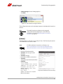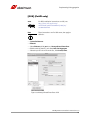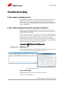
1
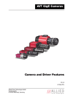
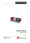
Allied Vision GigE Cameras Installation Manual GigE Vision Cameras V1.2.0 20 March 2015 Allied Vision Technologies GmbH Taschenweg 2a D-07646 Stadtroda, Germany Legal notice Trademarks Microsoft, Windows, and Windows 7 are either registered trademarks or trademarks of Microsoft Corporation in the United States and/or other countries. Unless stated otherwise, all trademarks appearing in this document of Allied Vision Technologies are brands protected by law. Warranty The information provided by Allied Vision Technologies is supplied without any guarantees or warranty whatsoever, be it specific or implicit. Also, excluded are all implicit warranties concerning the negotiability, the suitability for specific applications or the non-breaking of laws and patents. Even if we assume that the information supplied to us is accurate, errors and inaccuracy may still occur. Copyright All texts, pictures and graphics are protected by copyright and other laws protecting intellectual property. It is not permitted to copy or modify them for trade use or transfer, nor may they be used on websites. Allied Vision Technologies GmbH 03/2015 All rights reserved. Managing Director: Mr. Frank Grube Tax ID: DE 184383113 Headquarters: Taschenweg 2a D-07646 Stadtroda, Germany Tel: +49 (0)36428 6770 Fax: +49 (0)36428 677-28 e-mail: [email protected] AVT GigE Cameras Installation Manual V1.2.0 2 Contents Contacting Allied Vision .................................................................................. 5 Introduction ............................................................................................................ 6 Document history............................................................................................................ 6 Manual conventions......................................................................................................... 7 Styles ....................................................................................................................... 7 Symbols .................................................................................................................... 7 Additional information..................................................................................................... 8 Allied Vision accessories............................................................................................... 8 Allied Vision software .................................................................................................. 8 Safety instructions ............................................................................................10 General safety instructions.............................................................................................. 10 Sensor safety instructions ............................................................................................... 11 Changing filters safety instructions................................................................................... 11 Safety instructions for board level cameras (only Manta and Prosilica GB) ................................ 12 Getting started .....................................................................................................14 GigE Vision camera .................................................................................................... 14 Optics..................................................................................................................... 14 GigE Vision software .................................................................................................. 15 Overview of installation.................................................................................................. 15 Installing hardware............................................................................................16 Installing Gigabit Ethernet network card............................................................................ 16 Configuring Ethernet adapter .......................................................................................... 17 Installing Ethernet adapter driver ................................................................................ 17 Modifying Ethernet adapter IP address .......................................................................... 17 Optimizing Ethernet adapter ....................................................................................... 19 Installing camera software ...........................................................................22 Overview of software installation...................................................................................... 22 Downloading camera drivers............................................................................................ 22 Installing VIMBA Viewer ................................................................................................. 22 Installing GigE Sample Viewer.......................................................................................... 24 Starting the camera ..........................................................................................25 Power up ..................................................................................................................... 25 Connect to host application............................................................................................. 25 Using Allied Vision viewer applications ................................................26 Using VIMBA Viewer....................................................................................................... 26 Launching application ............................................................................................... 26 AVT GigE Cameras Installation Manual V1.1.0 3 Opening live view: Viewer toolbar................................................................................. 27 Adjusting camera controls: Controller window ................................................................ 28 Camera information: Information window ...................................................................... 28 Live histogram ......................................................................................................... 29 Using GigE Sample Viewer ............................................................................................... 30 Launching application ............................................................................................... 30 Opening live view...................................................................................................... 30 Adjusting camera controls .......................................................................................... 31 Live histogram ......................................................................................................... 31 Camera information................................................................................................... 31 Event channel .......................................................................................................... 32 RS232 serial interface................................................................................................ 33 Seek camera ............................................................................................................ 33 Exporting camera settings .......................................................................................... 34 Modifying camera IP address ....................................................................35 For VIMBA users ............................................................................................................ 35 For PvAPI users ............................................................................................................. 36 Using multiple cameras ..................................................................................38 Single Ethernet port .................................................................................................. 39 Multiple Ethernet ports .............................................................................................. 40 Implementing link aggregation ..................................................................42 When is LAG needed? ..................................................................................................... 42 Configuring Link Aggregation .......................................................................................... 43 Multicasting configuration ............................................................................46 Troubleshooting ..................................................................................................47 Is the camera getting power? ...................................................................................... 47 Is the camera powered, but not detected in viewer? ......................................................... 47 Is the camera listed in Viewer but can't acquire images? ................................................... 49 How to minimize/eliminate dropped packets? ................................................................ 50 Troubleshooting for Bigeye G cameras only (IOD mode) .................................................... 51 Additional references ......................................................................................52 Index...........................................................................................................................53 AVT GigE Cameras Installation Manual V1.1.0 4 Contacting Allied Vision Contacting Allied Vision Info • Technical information: http://www.alliedvision.com • Support: [email protected] Allied Vision Technologies GmbH (Headquarters) Taschenweg 2a 07646 Stadtroda, Germany Tel.: +49 36428-677-0 Fax: +49 36428-677-28 e-mail: [email protected] Allied Vision Technologies Canada Inc. 101-3750 North Fraser Way Burnaby, BC, V5J 5E9, Canada Tel.: +1 604-875-8855 Fax: +1 604-875-8856 e-mail: [email protected] Allied Vision Technologies Inc. 38 Washington Street Newburyport, MA 01950, USA Toll Free number +1 877-USA-1394 Tel.: +1 978-225-2030 Fax: +1 978-225-2029 e-mail: [email protected] Allied Vision Technologies Asia Pte. Ltd. 82 Playfair Road #07-02 D’Lithium Singapore 368001 Tel.: +65 6634-9027 Fax: +65 6634-9029 e-mail: [email protected] Allied Vision Technologies (Shanghai) Co., Ltd. 2-2109 Hongwell International Plaza 1602# ZhongShanXi Road Shanghai 200235, China Tel.: +86 (21) 64861133 Fax: +86 (21) 54233670 e-mail: [email protected] AVT GigE Cameras Installation Manual V1.1.0 5 Introduction Introduction This GigE Installation Manual provides instructions for first time use of Allied Vision GigE cameras. Powering up the camera, installing Allied Vision drivers and related software, and enabling users to get the camera up and running are the focus of this document. For information on camera dimensions, feature overview, I/O definition, trigger timing waveforms, frame rate performance, and camera cleaning instructions please refer to the Allied Vision Technical Manuals unique for each camera family. For detailed information on camera features and controls specific to the Allied Vision GigE cameras refer to the GigE Camera and Driver Attributes and GigE Features Reference documents. www Allied Vision product literature: http://www.alliedvision.com/en/support/technicaldocumentation Document history Version Date Remarks V1.0.0 2013-Jul-04 New Manual – RELEASE Status V1.0.1 2013-Oct-02 • • • Added information on how to minimize/eliminate dropped packets on page 50 Removed camera cleaning section from the manual Updated links for PvAPI SDK and Gigabit Ethernet cameras home page throughout the manual V1.1.0 2014-Jul-22 • • Added Goldeye G Updated Index V1.2.0 2015-Mar-20 • • • Updated Allied Vision logo Replaced old links with new Allied Vision website links Changed file name from ‘GigE Camera and Driver Features’ to ‘GigE Features Reference’ Table 1: Document history AVT GigE Cameras Installation Manual V1.1.0 6 Introduction Manual conventions To give this manual an easily understood layout and to emphasize important information, the following typographical styles and symbols are used: Styles Style Function Example Bold Programs, inputs, or highlighting important information bold Courier Code listings etc. Input Upper case Register REGISTER Italics Modes, fields Mode Parentheses and/or blue Links (Link) Table 2: Styles Symbols Note This symbol highlights important information. Caution www This symbol highlights important instructions. You have to follow these instructions to avoid malfunctions. This symbol highlights URLs for further information. The URL itself is shown in blue. Example: http://www.alliedvision.com AVT GigE Cameras Installation Manual V1.1.0 7 Introduction Additional information This section provides information on accessories and available software for Allied Vision GigE cameras. Allied Vision accessories Note Allied Vision offers a wide range of accessories for the use of Allied Vision GigE cameras and the easy integration in already existing applications. • • www Gigabit Ethernet accessories including standard GigE components as well as PoE capable GigE components. Lenses for corresponding sensor sizes and resolutions. (Contact Allied Vision Support for further information.) Accessories: Please contact Allied Vision sales representative or your local Allied Vision dealer for information on accessories: http://www.alliedvision.com/en/about-us/where-weare.html For more information on third-party hardware components tested with Allied Vision GigE cameras, read: Application Note: Hardware Selection for Allied Vision GigE Cameras: http://www.alliedvision.com/fileadmin/content/documents/ products/cameras/various/appnote/ Hardware_Selection_for_Allied_Vision_GigE_Cameras.pdf Allied Vision software All software packages provided by Allied Vision are free of charge and contain the following components: • Drivers • Software Development Kit (SDK) for camera control and image acquisition • Examples based on the provided APIs of the SDK • Documentation and release notes • Viewer application to operate/configure the cameras www All software packages (including documentation and release notes) provided by Allied Vision can be downloaded at: http://www.alliedvision.com/en/support/softwaredownloads AVT GigE Cameras Installation Manual V1.1.0 8 Introduction Third-party software In addition to the software provided by Allied Vision, there are numerous GigE Vision Standard compliant third-party software options available. In general, third-party software provides increased functionality such as image processing and video recording. Allied Vision’s Vimba SDK is based on the GenICam standard. GenICam-based third-party software automatically connects with Vimba's transport layers. Additionally, Vimba includes the Cognex Adapter for VisionPro. AVT GigE Cameras Installation Manual V1.1.0 9 Safety instructions Safety instructions This chapter describes safety instructions/cautions valid for Allied Vision GigE cameras and special safety instructions/cautions depending on the camera model used. General safety instructions Note • • • There are no switches or parts inside the camera that require adjustment. The guarantee becomes void upon opening the camera casing. If the product is disassembled, reworked or repaired by anyone other than a recommended service person, Allied Vision or its suppliers are not responsible for the subsequent performance or quality of the camera. The camera does not generate dangerous voltages internally. Note IR cut filters for visible light cameras: All color models are equipped with an optical filter to eliminate the influence of infrared light hitting the sensor. Please be advised that, as a side effect, this filter reduces sensitivity in the visible spectrum. See camera technical manual for the location of IR cut filter. AVT GigE Cameras Installation Manual V1.1.0 10 Safety instructions Sensor safety instructions Caution Sensor may be damaged Light intensity or exposure time exceeding the saturation of the sensor may damage the sensor irreparably. This may occur in the following situations: • • • Laser light hitting the sensor directly Bright light sources (e.g. sunlight) hitting the sensor directly Camera is exposed to X-rays Damages may be caused by: • • Overheating of color filters, microlenses or pixel structures Accelerated aging of color filters or pixel structures Caution To avoid sensor damage • • • • • • Use light source with lower intensity Use external shutter Use optical filters Use lens cap (when camera not in use) Vary local light spot / laser spot on sensor X-rays: – Keep camera out of X-ray path. Guide light source via mirrors to the sensor – Use lead glass to protect lens and sensor – Use lead jacket for the body of the camera The warranty does not cover damaged cameras caused by X-ray applications or too much light/laser light. Changing filters safety instructions Caution • Mount/dismount lenses and filters in a dust-free environment, and do not use compressed air (which can push dust into cameras and lenses). • Use only optical quality tissue/cloth if you must clean a lens or filter. Ask your dealer if you are not familiar with these procedures. AVT GigE Cameras Installation Manual V1.1.0 11 Safety instructions Safety instructions for board level cameras (only Manta and Prosilica GB) Note Caution-ESD Read the Manta / Prosilica GB Technical Manual and these safety instructions before use. Abuse or misapplication of the camera may result in limited warranty or cancellation of warranty. Board level cameras: ESD warnings • • • • • Board level cameras are delivered without housing. Handle the sensor board and main board with care. Do not bend the boards. Do not touch the components or contacts on a board. Hold a board by its edges. Sensor board and main board are sensitive to electrostatic discharge. To avoid possible damage, handle all static-sensitive boards and components in a staticsafe work area. Follow the procedures below. ESD (electrostatic discharge): Static electricity can damage the sensor board or the main board of your board level cameras. To prevent static damage, discharge static electricity from your body before you touch any of your broad level camera’s electronic components, such as sensor board or main board. To do so, use a static-safe work area with static-dissipative mat and wear a staticdissipative wrist strap. Do not hold any components of your board level cameras against your clothing. Even if you are wearing a wrist strap, your body is grounded but your clothes are not. Do not remove the sensor board and main board from its anti-static packaging unless your body is grounded. ESD shielding: To protect the boards from radiation of other modules or devices use a special ESD protective housing. AVT GigE Cameras Installation Manual V1.1.0 12 Safety instructions Caution Board level cameras: General warnings • • • • • • Caution Be sure that all power to your board level camera is switched off before mounting the sensor board or making connections to the camera. Do not connect or disconnect any cables during an electrical storm. Do not use your board level cameras during an electrical storm. To help avoid possible damage to the sensor board or main board, wait 5 seconds after power is switched off, before connecting or disconnecting any cable to the board level cameras. Keep your board level cameras away from radiators and heat sources. Avoid contact of board level cameras with liquids. Board level cameras: Loading • • Avoid any mechanical forces to the board level cameras, the boards and its components, especially torsional, tensile and compressive forces. To avoid damages of the boards, provide cables with an external pull relief so that no force is applied to the connectors itself. Caution Board level cameras: Dirty environments • • Always use clean boards. To protect the board level cameras from debris always use in a clean environment or a protective housing. AVT GigE Cameras Installation Manual V1.1.0 13 Getting started Getting started This chapter describes the components required for your camera system: GigE Vision camera Allied Vision offers the following GigE Vision camera families: – – – – – Bigeye G Goldeye G Mako Manta Prosilica GB – – – – – Prosilica GC Prosilica GE Prosilica GS Prosilica GT Prosilica GX This guide can be applied to all of these families. Follow the links below to learn more about GigE cameras from Allied Vision. www Follow this link to learn about GigE cameras from Allied Vision. http://www.alliedvision.com/en/products/cameras Optics Allied Vision GigE cameras offer various mechanical interfaces for installing a lens including C-Mount, CS-Mount, F-Mount, M12-Mount, M42-Mount, M58Mount, and Canon EF-Mount. Lenses can be purchased directly from Allied Vision or from an Allied Vision distributor. Users need to select the desired focal length and appropriate optical format for the target camera model. www www See Modular Concept for more information on mechanical interface options for specific Allied Vision GigE cameras: http://www.alliedvision.com/fileadmin/content/documents/ products/cameras/various/modular-concept/ Modular_concept_external.pdf Allied Vision offers a number of lenses. • To purchase a lens, please contact Allied Vision sales representative or your local Allied Vision dealer: http://www.alliedvision.com/en/about-us/where-weare.html • For assistance in choosing a suitable lens for your Allied Vision GigE camera, please contact [email protected]. AVT GigE Cameras Installation Manual V1.1.0 14 Getting started GigE Vision software Allied Vision provides several software packages that support our GigE Vision cameras. User can target the following operating systems and a variety of CPU architectures: • Windows, Linux (supported by both VIMBA and PvAPI SDKs) • QNX or OSX (supported by PvAPI SDK only) www VIMBA is Allied Vision's future-proof SDK for all current and upcoming Allied Vision cameras with GigE Vision, FireWire (IEEE 1394) and USB Vision interfaces. Visit the link below for more information. http://www.alliedvision.com/en/products/software www PvAPI SDK supports all GigE Vision cameras from Allied Vision on various operating systems, including Windows, Linux, OSX and QNX. See Legacy Software section of the following web page for more information. http://www.alliedvision.com/en/support/softwaredownloads Allied Vision GigE cameras are GigE Vision v1.2 compliant. This means they are compatible with third-party software which offers a GigE Vision driver. Overview of installation This is an overview of the installation process: follow the hyperlinks to read the step-by-step instructions. • Install Gigabit Ethernet network card and configure network card (Jumbo Frames, Receive Descriptors, Performance Options and IP address settings): See chapter Installing hardware on page 16. • Install Allied Vision SDKs plus corresponding Viewers: See chapter Installing camera software on page 22. • Connect camera to PC or laptop and ensure that the camera is powered: See chapter Starting the camera on page 25. • Acquiring your first image with VIMBA Viewer and GigE Sample Viewer: Read chapter Using Allied Vision viewer applications on page 26. AVT GigE Cameras Installation Manual V1.1.0 15 Installing hardware Installing hardware This chapter describes the hardware installation and configuration of Gigabit Ethernet network cards (PC or laptop) for optimum system performance when using a GigE Vision camera. Installing Gigabit Ethernet network card GigE Vision cameras can operate on 10/100, or Gigabit speed Ethernet adapters. In order to take advantage of maximum camera frame rates, a Gigabit speed adapter is required. If your host computer has an available Ethernet port, this can be used with Allied Vision GigE cameras. We recommend that your camera system uses a dedicated Ethernet port not shared with internet or local area networks. If more ports are needed, or your existing Ethernet adapter is unable to operate at Gigabit Ethernet speeds, installing additional hardware may be required. For desktop systems For laptops Use a PCI Express bus Ethernet adapter. Use an expansion slot via an ExpressCard. Note www www Caution Verify that there is an available and compatible interface slot on the host computer before purchasing the desired Ethernet adapter card. For a list of Ethernet adapters available for purchase from Allied Vision, please contact Allied Vision sales representative or your local Allied Vision dealer: http://www.alliedvision.com/en/about-us/where-weare.html A list of Allied Vision recommended Ethernet adapters is available on the Allied Vision website. http://www.alliedvision.com/fileadmin/content/documents/ products/cameras/various/appnote/ Hardware_Selection_for_Allied_Vision_GigE_Cameras.pdf Allied Vision recommends Category 6 or higher rated Ethernet cables. A different rating may not sustain peak interface bandwidth; leading to lost connectivity or image data coming from the camera. AVT GigE Cameras Installation Manual V1.1.0 16 Installing hardware Configuring Ethernet adapter 1. PC: Install the (second) Gigabit Ethernet network card in your host computer according to the instructions you got from your network card manufacturer. Laptop: Insert the Gigabit Ethernet ExpressCard into your laptop. 2. Cancel the Found new Hardware Wizard window that may appear when Windows detects your network card. Installing Ethernet adapter driver 3. Install the network card driver from your network card manufacturer. This manual references the Intel Gigabit CT series, an equivalent can be found from other manufacturers. www Follow the link below to download the latest drivers for Intel adapters. http://www.intel.com/p/en_US/support/detect Run installation application provided by driver manufacturer. If no installation application is provided, update the driver manually: [Windows 7] – Start – Control Panel – Hardware and Sound – Device Manager – Expand Network Adapter – Right-click Adapter device name – Properties – Driver tab – Update driver – Install from specific location (identify installation directory) Figure 1: Adapter properties, driver tab, Windows 7 Modifying Ethernet adapter IP address 4. After initial Ethernet adapter hardware installation, connect the Ethernet adapter directly to the camera. The default configuration assigns an IP address automatically using the Link-Local Address range of 169.254.xxx.xxx or an address defined the by the DHCP server, if present. AVT GigE Cameras Installation Manual V1.1.0 17 Installing hardware Users can fix the adapter address to minimize the time required for a camera to be recognized by the host application. Systems that employ multiple Ethernet adapters connected to multiple cameras will also be required to fix the address of the Ethernet adapter. [Windows 7] – Start, Control Panel – Network and Internet – View network status and tasks – Change adapter settings – Right-click Network Connection – Properties – Select Internet Protocol Version 4 and click Properties – Select Use the following IP address: IP Address: 169.254.100.1 Subnet mask: 255.255.0.0 Default gateway: blank Figure 2: Windows - Fixed IP address, Auto IP range [Linux] – Terminal: ifconfig – Note eth# of NIC connected to camera – Terminal: sudo gedit /etc/network/interfaces – Add/edit: auto eth6 iface eth6 inet static address 169.254.100.1 netmask 255.255.0.0 Where, eth6 is name of NIC connected to camera. Figure 3: Interfaces file for static IP, Linux Ubuntu 10.04 AVT GigE Cameras Installation Manual V1.1.0 18 Installing hardware [OSX] (PvAPI only) – System Preferences – Network – Select Ethernet, click Advanced – TCP/IP tab: Configure IPv4: Manually IPv4 Address: 169.254.100.1 Subnet Mask: 255.255.0.0 Router: Blank Figure 4: Interfaces file for static IP, Linux Ubuntu 10.04 Optimizing Ethernet adapter 5. The Ethernet adapter should be adjusted to improve system performance when using a GigE Vision camera. This performance is related to minimizing CPU usage and dropped or resent packets. Edit the Ethernet adapter driver properties according to the values in the table below. The names and availability of the properties listed may vary depending on adapter manufacturer and model. Properties Value Packet size (MTU) Interrupt Moderation Rate Transmit buffers Receive buffers 8228 or larger Extreme 256 bytes Max setting available Table 3: Ethernet adapter performance settings Allied Vision GigE camera’s factory/default settings configure the camera packet size to 8228. The host adapter needs to support a packet size of equal or larger size to stream from the camera. Note If adapter packet size support is limited to 1500 bytes, as on 10/100 speed NICs, the camera packet size can be reduced using VIMBA Viewer / GigE Sample Viewer and saved to an on board camera power up config file. PvAPI users: See ConfigFile in the GigE Camera and Driver Attributes document. VIMBA users: See SavedUserSets in the GigE Features Reference document. AVT GigE Cameras Installation Manual V1.1.0 19 Installing hardware Adjusting camera packet size [Windows 7, Intel Gigabit CT] – Start, Control Panel – Hardware and Sound – Device Manager – Network Adapter – Right-click Adapter device name – Properties – Advanced tab – Settings: Jumbo Packet - Value: 9014 Bytes Figure 5: Setting jumbo packets Note The settings list in the advanced adapter settings may be different between different types/brands of Gigabit Ethernet network cards. Common expressions are Jumbo Frames or Jumbo Packet. If Jumbo Frames or Jumbo Packet does not appear in this list, your network card may not support it. Without this capability, you may not be able to achieve the full performance of the camera. [Linux] – Terminal: sudo gedit /etc/network/interfaces – Add: mtu 8228 to appropriate interface. – Or, to temporarily increase packet size: Terminal: sudo ifconfig eth0 mtu 8228, where eth0 is the camera NIC. AVT GigE Cameras Installation Manual V1.1.0 20 Installing hardware [OSX] (PvAPI only) – System Preferences – Network – Select Ethernet, click Advanced – Ethernet tab: Configure: Manually Speed: 1000baseT Duplex: full-duplex MTU: Jumbo (9000) Figure 6: Ethernet settings OSX Snow Leopard Adjusting buffers and moderation rate [Windows 7, Intel Gigabit CT] – Start, Control Panel – Hardware and Sound – Device Manager – Network Adapter – Right-click Adapter device name – Properties – Advanced tab – Performance Options – Settings: Interrupt Moderation Rate Value: Extreme – Settings: Transmit Buffers Figure 7: Intel adapter performance Value: 256 bytes options. Windows 7, Intel Gigabit CT – Settings: Receive Buffers Value: Max allowable [Linux, QNX, OSX] Support for buffer size control and moderation rate settings varies greatly between network card driver providers. www Follow the link below for a detailed guide to using the Linux e1000 Base Driver for the Intel PRO/1000 family of adapters: http://www.intel.com/support/network/adapter/pro100/sb/CS032516.htm?wapkw=e1000+linux+base+driver+for+the+intel+pr o%2f1000 AVT GigE Cameras Installation Manual V1.1.0 21 Installing camera software Installing camera software This chapter presents instructions for software installation specific to Windows 7. Allied Vision GigE cameras can be operated under earlier versions of Windows including XP. Suggestions specific to Linux, QNX and OSX are also offered when applicable. Allied Vision offers two main SDKs for its GigE Vision cameras— VIMBA and PvAPI. Overview of software installation This is an overview for the software installation: follow the hyperlinks to read the step-by-step instructions. • Install VIMBA SDK plus corresponding VIMBA Viewer: Read Installing VIMBA Viewer on page 22. • Install PvAPI SDK and corresponding GigE Sample Viewer: Read Installing GigE Sample Viewer on page 24. Downloading camera drivers Allied Vision GigE cameras work with any or all of the following software options: www VIMBA Viewer or VIMBA SDK: http://www.alliedvision.com/en/products/software www GigE Sample Viewer or PvAPI SDK, see the Legacy Software section: http://www.alliedvision.com/en/support/softwaredownloads Installing VIMBA Viewer [Windows 7] • Go to install directory. • Click AVTVimba.exe. AVT GigE Cameras Installation Manual V1.1.0 22 Installing camera software • • Select an installation level suitable for your needs. For first time users, installation level Camera Demonstration is recommended. Click Start. [Linux] Necessary runtime libraries for executing VIMBA Viewer are available with VIMBA SDK package. • VIMBA ships as a tarball. Uncompress the archive with the command tar -xf ./AVTVimba.tgz to a directory you have writing privileges for. This creates a directory named AVTVimba. • Navigate to AVTVimba/AVTGigETL and execute the shell script Install.sh with root privileges (e.g. sudo ./Install.sh). • VIMBA Viewer is now ready to use and it can be found in Vimba/Viewer/Bin. Note VIMBA Viewer must be run with root privileges (e.g. sudo -E ./VimbaViewer) if you want to change the IP configuration of a camera in a foreign subnet. Running it as root user instead of using sudo -E requires you to set the environment variables manually. Figure 8: VIMBA Viewer, Linux Ubuntu 12.04 AVT GigE Cameras Installation Manual V1.1.0 23 Installing camera software Installing GigE Sample Viewer First time users may want to install the GigE Sample Viewer which offers an excellent introduction to using the camera. Advanced users wishing to develop their own software should download PvAPI SDK. Source code for the GigE Sample Viewer is provided in the examples directory. A filter driver installation executable is also provided with the SDK. [Windows 7] • Go to install directory. • Click Allied_Vision_Technologies_GigE_Viewer_Installer.exe. • A message appears indicating the publisher could not be verified, select Run to continue. • Follow the prompts as requested, when asked “Would you like to install the Filter driver?” select Yes. Note The AVT Filter miniport driver works alongside the native Ethernet adapter driver to optimize CPU usage, and minimize dropped packets. It is available only on Windows. [Linux] • Precompiled versions of GigE Sample Viewer are available in the AVT GigE ‘SDK/bin-pc directory. • Run as root, e.g. “sudo ./SampleViewer”, allowing the OS to boost the priority of the Allied Vision driver thread, the driver to bind directly to the NIC adapter, and minimize dropped packets. Users who feel running as root compromises their system security may find the following implementation satisfactory: – Set the executable owner as root. – Set the “setuid” permission bit on the executable. – In code, when application starts, use capset() to release all but these privileges: CAP_SYS_NICE, CAP_NET_ADMIN, CAP_NET_BROADCAST, CAP_NET_RAW. The application starts with all root privileges, but it drops them immediately after startup. AVT GigE Cameras Installation Manual V1.1.0 24 Starting the camera Starting the camera Power up A camera power adapter for each GigE camera is available from Allied Vision. Please consult the camera technical manual for connector definition and voltage specifications www Allied Vision Product literature http://www.alliedvision.com/en/support/technicaldocumentation Caution For Goldeye G, Prosilica, Mako, and Manta cameras: • • • Use only DC power supplies with insulated cases. For all power connections use only shielded cables to avoid electromagnetic interferences. Goldeye G, Mako, Manta, and Prosilica GT PoE models can source power from: – 802.3af (100 MBit/s and 1000 MBit/s), and – 802.3at compliant PSE devices (Power Sourcing Equipment): such as switches injectors or NICs Caution Bigeye G cameras Operate Bigeye G cameras at 12 V (+ 5 %). The current is limited to max. 3.0 A. Operating Bigeye G cameras outside these specifications may cause damage. Connect to host application Use a Category 6 or higher rated Ethernet cable to connect the camera to the host adapter. Crossover cabling is not required, but works—the camera has circuitry to determine if a crossover cable is being used. www Accessories: Please contact Allied Vision sales representative or your local Allied Vision dealer for information on accessories: http://www.alliedvision.com/en/about-us/where-weare.html AVT GigE Cameras Installation Manual V1.1.0 25 Using Allied Vision viewer applications Using Allied Vision viewer applications This chapter describes the use of two viewer applications offered by Allied Vision—VIMBA Viewer and GigE Sample Viewer. The viewer applications are used to stream live view images from the camera, adjust the camera parameters and test functionality. www VIMBA Viewer can be downloaded from the Allied Vision website: http://www.alliedvision.com/en/support/softwaredownloads www GigE Sample Viewer can be downloaded from the Legacy Software section: http://www.alliedvision.com/en/support/softwaredownloads Using VIMBA Viewer This section describes main features of the VIMBA Viewer. Launching application 1. Launch the VIMBA Viewer application. Wait for the camera to appear in the “Detected Cameras” list. This may take up to one minute in network card “Obtain an IP address automatically” mode. Figure 9: VIMBA Viewer window If a camera does not appear after some time, try the following: • Confirm the camera is powered. • Confirm the Ethernet cable is connected to the host PC. AVT GigE Cameras Installation Manual V1.1.0 26 Using Allied Vision viewer applications • Confirm that camera IP and Ethernet adapter are on the same subnet. For more information refer to Modifying camera IP address on page 35. 2. Select the desired camera from “Detected Cameras” list. 3. A new camera window appears, as shown in figure 10. This camera window consists of the following components: – Viewer toolbar: controls to customize the live camera view – Controller window: shows camera controls – Information window: displays camera and event information – Histogram window Viewer toolbar Controller window Information window Camera stats Figure 10: Camera window in VIMBA Viewer The camera window supports a fully dockable layout that allows user to customize their workspace. Note If any of the above components of the camera window is missing, then: – Right-click on menu or toolbar – Select the missing component Opening live view: Viewer toolbar Press freerun button in the viewer toolbar, shown left. This starts continuous acquisition from the camera using default camera settings. It can be confirmed by stats at the bottom of camera window, as shown in figure 10. “Running” means continuous acquisition, whereas, “Ready” means camera is ready to acquire images. The freerun button is used to start/stop the live view. AVT GigE Cameras Installation Manual V1.1.0 27 Using Allied Vision viewer applications If the images are too dark, point the camera directly at a light source to ensure images are not being dropped. If no images appear proceed to chapter Troubleshooting on page 47. Adjusting camera controls: Controller window The controller window, as shown in figure 10, is used to configure the camera frame rate, exposure time, color balance, imaging mode, strobe functionality, pixel format, and much more. www A detailed explanation of camera controls can be found in GigE Features Reference document: http://www.alliedvision.com/fileadmin/content/documents/ products/cameras/various/features/ GigE_Features_Reference.pdf Camera information: Information window The information window, as shown in figure 11, consists of the following functionalities. Click the logging icon, shown left. The logging window opens. It provides camera identifying information including the serial and ID number. Click the event viewer icon, shown left. The events viewer window opens. This is a tool used to monitor in-camera events such as EventAcquisitionEnd, EventAcquisitionStart, EventExposureEnd, etc. The factory default settings disable all event notifications. Use the camera controls to select which events to monitor. Figure 11: VIMBA Viewer events and controls AVT GigE Cameras Installation Manual V1.1.0 28 Using Allied Vision viewer applications Live histogram Start live view from the camera by selecting freerun button. Click the histogram icon in the viewer toolbar, shown left. This launches a live histogram. A histogram graphs number of pixels on the vertical axis and digital number value on the horizontal axis. Figure 12: Live histogram in VIMBA Viewer Note Histogram is ONLY supported for the following pixel formats: • • • • • Mono8 RGB8 BGR8 YUV444 BayerRG12Packed AVT GigE Cameras Installation Manual V1.1.0 29 Using Allied Vision viewer applications Using GigE Sample Viewer This section describes main features of GigE Sample Viewer. Launching application Start the GigE Sample Viewer application. Wait for the camera to appear under Host. If a camera does not appear after some time, try the following: • Confirm the camera is powered. • Confirm the Ethernet cable is connected to the host PC. • Modify the Ethernet adapter and/or Camera IP such that they are on the same subnet. For more information refer to Modifying camera IP address on page 35. Figure 13: camera window If the camera still does not appear, proceed to chapter Troubleshooting on page 47. Opening live view Select the desired camera from the cameras window of the GigE Sample Viewer. Click the eyeball icon. This opens a new view window. Using default camera settings, this starts continuous acquisition from the camera using freerun trigger mode. If the images are too dark, point the camera directly at a light source to ensure images are not being dropped. If no images appear proceed to Troubleshooting on page 47. Figure 14: GigE Sample Viewer live view AVT GigE Cameras Installation Manual V1.1.0 30 Using Allied Vision viewer applications Adjusting camera controls Select the desired camera from the cameras window of the GigE Sample Viewer. Click the wrench icon to open controls window. The controls window is used to configure the camera frame rate, exposure time, color balance, imaging mode, strobe functionality, pixel format, and much more. Figure 15: GigE Sample Viewer controls window A detailed explanation of camera controls can be found in the GigE Camera and Driver Attributes document. www GigE Camera and Driver Attributes download link: http://www.alliedvision.com/fileadmin/content/documents/ products/cameras/various/features/ GigE_Camera_and_Driver_Attributes.pdf Live histogram Start live view from the camera by selecting the eyeball icon. Click the histogram icon, shown left. This launches an 8-bit live histogram. A histogram graphs number of pixels on the vertical axis and digital number value on the horizontal axis. Camera information Select the desired camera from the cameras window of the GigE Sample Viewer. Click the information icon, shown left. The information window provides camera identify information including the serial number and part number. AVT GigE Cameras Installation Manual V1.1.0 31 Using Allied Vision viewer applications Figure 16: GigE Sample Viewer information and histogram windows Event channel Select the desired camera from the cameras window of the GigE Sample Viewer. Click the film icon, shown left, to open the events window. This is a tool used to monitor in-camera events such as AcquisitionEnd, ExposureStart, ExposureEnd, etc. The factory default settings disable all event notifications. Use the camera controls to select which events to monitor. View the EventID to understand the display format in the Events window. Figure 17: GigE Sample Viewer events and controls AVT GigE Cameras Installation Manual V1.1.0 32 Using Allied Vision viewer applications RS232 serial interface Select the desired camera from the cameras window of the GigE Sample Viewer. Click the serial icon, shown left, to open the serialIO window. This tool controls the camera’s RS232 port which communicates across the RXD and TXD pins on the camera IO port. All Allied Vision GigE cameras except Mako offer an RS232 port. Figure 18: GigE Sample Viewer serialIO window RS232 communication can be used for interfacing the camera to motorized lenses, temperature and pressure sensors, camera position motors, and other applications. Seek camera Select the desired camera from the cameras window of the GigE Sample Viewer. Click the seek icon, shown left. The seek camera window appears. This is used when camera UDP discover broadcast packets are either disabled, or blocked by hardware or network administrator preventing the camera from being recognized by the GigE Sample Viewer. Enter the camera’s IP address into the window shown below. Figure 19: GigE Sample Viewer seek camera AVT GigE Cameras Installation Manual V1.1.0 33 Using Allied Vision viewer applications Exporting camera settings Select the desired camera from the cameras window of the GigE Sample Viewer. Click the floppy disk icon, shown left. A file explorer window appears requesting a download location for the camera setup file. This file captures the current camera settings and creates a simple text file. This file can be uploaded to other cameras allowing both units to utilize the same camera settings. www Load camera settings to other cameras using the CamSetup example code found in PvAPI SDK from Allied Vision. See the application note: http://www.alliedvision.com/fileadmin/content/documents/ products/cameras/various/appnote/PvAPI__Saving_and_Loading_Camera_Attributes_with_Text_File.pdf Figure 20: GigE Sample Viewer exporting camera setup Figure 21: Camera settings text file exported from the camera AVT GigE Cameras Installation Manual V1.1.0 34 Modifying camera IP address Modifying camera IP address Allied Vision GigE cameras support a number of IP addressing modes. Cameras shipped from the factory are configured to DHCP. If a DHCP server is not present, the camera uses the LLL / Auto IP configuration mode. Configuration Mode Description VIMBA: DHCP PvAPI: DHCP VIMBA: LLL PvAPI: Auto IP VIMBA: Persistent PvAPI: Fixed Obtain an IP address automatically using DHCP (Fallback to LLL/Auto IP) Obtain an IP address automatically (169.254.xxx.xxx) IP address is assigned by the user Table 4: Camera IP configuration modes The camera IP address can be fixed by changing the configuration mode and defining the desired address. For VIMBA users The camera may not be detected by the viewer if the IP address of the adapter is not on the same subnet as the camera. In this case, start by configuring the adapter to Auto IP mode. 1. Ensuring that the adapter is in Auto IP configuration, launch the VIMBA Viewer application. 2. Wait for the camera to be listed in the “Detected Cameras” list. 3. Right-click the desired camera and select Open CONFIG. Figure 22: Example - Opening camera in configuration mode using VIMBA Viewer (Windows OS) AVT GigE Cameras Installation Manual V1.1.0 35 Modifying camera IP address 4. A new window opens. In the controller window, go to GigE/Persistent and provide the desired values. 5. Go to GigE/Configuration/IP Configuration Mode. Set IP Configuration Mode = Persistent; and execute IP Configuration Apply command. Figure 23: Example - Setting fixed camera IP address in VIMBA Viewer (Windows OS) For PvAPI users [Windows 7] With the camera(s) connected to the host, run the IPConfig program. This application is packaged with the GigE Sample Viewer download. – Select the camera(s) you wish to alter, select Change. – Select Use the following IP address. – Enter desired IP address, subnet mask, and gateway. Figure 24: Setting fixed camera IP address using IPConfig application AVT GigE Cameras Installation Manual V1.1.0 36 Modifying camera IP address [Linux, OSX, QNX] With the camera(s) connect to the host, run the CLipConfig program included in the AVT GigE SDK/bin-pc directory. Source code is included in the examples. Figure 25: CLipConfig application command line options AVT GigE Cameras Installation Manual V1.1.0 37 Using multiple cameras Using multiple cameras There is a number of different methods for configuring a multiple camera system. Most of these can be differentiated into two architectures: Single Ethernet port and Multiple Ethernet port. In order to determine which architecture is needed, start by calculating the amount of bandwidth required from the cameras based on the desired resolution, pixel format, frame rate and number of cameras. Bandwidth = Width x Height x Bytes Per Pixel x Frame Rate x Number of Cameras = Value in MBps (Megabytes per second) Example 1: Three GC1020 cameras, full resolution, Mono8 pixel format (1 byte per pixel), at 30 fps. Bandwidth usage = 1024 x 768 x 1 x 30 x 3 = 70.8 MBps Percentage of single port GigE bandwidth = 57%. Single port architecture is sufficient. Example 2: Three GC650 cameras, full resolution, Mono16 pixel format (2 bytes per pixel), at 90 fps. Bandwidth usage = 659 x 493 x 2 x 90 x 3= 175.4 MBps Percentage of single port GigE bandwidth =140%. Multiple port architecture is needed. Example 3: Three GC1380C cameras, full resolution, Bayer16 pixel format (2 bytes per pixel), 20 fps. Bandwidth usage = 1360 x 1024 x 2 x 20 x 3 = 167.1 MBps Percentage of single port GigE bandwidth = 134%. Multiple port architecture is needed. Gigabit Ethernet bandwidth is 1 Gbps (Gigabit per second) ~ 125 MBps (Megabytes per second). Example 1 can be accommodated using a single Ethernet port, whereas, example 2 and 3 require multiple Ethernet ports in order to increase the available bandwidth. AVT GigE Cameras Installation Manual V1.1.0 38 Using multiple cameras www For more information on StreamBytesPerSecond and camera pixel format, see: PvAPI users: GigE Camera and Driver Attributes document VIMBA users: GigE Features Reference document Single Ethernet port Multiple cameras are connected to a switch. The switch is connected to a single Ethernet port. This is the simplest multiple camera installation. The cameras can be managed using Auto IP, no additional configuration on the switch is necessary. Figure 26: Multi-camera network configuration using a switch and single Ethernet port This architecture combines bandwidth coming from each camera onto a single cable connected to the host. To prevent packet collision, resulting in dropped packets, the user is required the reduce StreamBytesPerSecond feature on each camera, such that the sum doesn’t exceed 125,000,000 Bps. Example: Camera 1: GE1900, full resolution, Mono8 pixel format, at 15 fps Bandwidth usage = 1920 x 1080 x 1 x 15 = 31,104,000 Bps Set StreamBytesPerSecond = 31,104,000 Bps. Camera 2: GE1650C, full resolution, Bayer GB8 / Bayer 8 pixel format, at 5 fps Bandwidth usage = 1600 x 1200 x 1 x 5 = 9,600,000 Bps Set StreamBytesPerSecond = 9,600,000 Bps. Camera 3: GC2450, full resolution, Mono8 pixel format, at 5 fps Bandwidth usage = 2448 x 2050 x 1 x 5 = 25,092,000 Bps Set StreamBytesPerSecond = 25,092,000 Bps. Total bandwidth consumed = 31,104,000 + 9,600,000 + 25,092,000 = 65,796,000 Bps AVT GigE Cameras Installation Manual V1.1.0 39 Using multiple cameras Figure 27: GigE Sample Viewer window, controls window showing StreamBytesPerSecond feature Multiple Ethernet ports Each camera is connected directly to an Ethernet port. No switch is used. This configuration is more complex and requires the user to manage host and camera IP addressing; however, it allows each camera to use the entire Gigabit interface bandwidth. Figure 28: Multi-camera network configuration using multiple Ethernet ports Camera and adapter IP addresses are managed with fixed IP addressing, as the IP address of each adapter needs to be on a unique subnet. A subnet is that part of the IP address that overlaps with the binary 1’s (decimal 255 in following example) of the subnet mask. Camera 1 169.254.100.2 255.255.255.0 Adapter 1 169.254.100.1 255.255.255.0 Camera 2 169.254.200.2 255.255.255.0 Adapter 2 169.254.200.1 255.255.255.0 Figure 29: Camera and adapter IP address example AVT GigE Cameras Installation Manual V1.1.0 40 Using multiple cameras The following steps are required to configure a multiple Ethernet port camera system: • Fix host adapter IP address • Fix camera IP address Note The host can be configured using multiple single port adapter cards, multiple dual port, quad port and so on. The same IP addressing model can be scaled to larger network configurations. Fix host adapter IP address – Refer to Modifying Ethernet adapter IP address on page 17. – Select Use the following IP address: Adapter1 IP Address: 169.254.100.1 Subnet mask: 255.255.255.0 Adapter2 IP Address: 169.254.200.1 Subnet mask: 255.255.255.0 Figure 30: IP configuration window for Adapter 1 Fix camera IP address – Refer to Modifying camera IP address on page 35. – Set the following IP addresses: Camera1 IP Address: 169.254.100.2 Subnet mask: 255.255.255.0 Adapter1 IP Address: 169.254.200.2 Subnet mask: 255.255.255.0 Figure 31: IPConfig camera IP address configuration window AVT GigE Cameras Installation Manual V1.1.0 41 Implementing link aggregation Implementing link aggregation The Prosilica GX series cameras offer two Gigabit Ethernet ports for image data transfer and control. Users can connect one or both ports on the Prosilica GX to Ethernet adapter ports on a host computer. The dual port approach requires the host computer to configure a Link Aggregate Group (LAG). A LAG configuration combines multiple Ethernet ports into a single data channel. Figure 32: Prosilica GX camera network configuration using multiple Ethernet ports When is LAG needed? Connecting both ports increases the available bandwidth to 240 MB/sec. This is beneficial for the following cases. • Need to use high(> 8 bits) bit depth pixel formats. • Highest frame rate is needed. www See Prosilica GX Technical Manual for resolution and ROI frame rate performance. http://www.alliedvision.com/en/support/technicaldocumentation/prosilica-gx-documentation www For more information on camera pixel format, see: PvAPI users: GigE Camera and Driver Attributes document VIMBA users: GigE Features Reference document The following examples show how to determine bandwidth consumption. If the value is greater than 125 MB, LAG is required. Example 1: GX1050 camera using Mono8 pixel format and outputting 100 fps Bandwidth usage = Resolution x Pixel format x Frame rate = 1024 x 1024 x 1 (1 byte for Mono8) x 100 ~ 105 MBps AVT GigE Cameras Installation Manual V1.1.0 42 Implementing link aggregation Percentage of single port GigE bandwidth ~ 84%, LAG is not required to operate the GX1050 camera at 100 fps in Mono8. Example 2: GX1050C using YUV422 pixel format and outputting 100 fps Bandwidth usage = 1024 x 1024 x 2 (2 byte for YUV422) x 100 ~ 210 MBps Percentage of single port GigE bandwidth ~ 168%, LAG is required to operate the GX1050C at 100 fps using YUV422. Configuring Link Aggregation The GX camera connected to host using LAG requires two host Ethernet adapter ports. Configure and optimize each Ethernet adapter port using steps outlined in Configuring Ethernet adapter on page 17. The following steps describe the setup of a link aggregate group. [Windows 7, Intel PT] – – – – – – – – Start, Control Panel Hardware and Sound Device Manager Network Adapter Right-click Adapter device name Properties Teaming tab Select Team the adapter with other adapters – Click New Team – The New Team Wizard window opens, choose a team name and click Next – Select the desired adapters corresponding to the ports to be used by the Prosilica GX camera, click Next Figure 33: Intel adapter properties teaming tab Figure 34: Team wizard adapter selection AVT GigE Cameras Installation Manual V1.1.0 43 Implementing link aggregation – Select team type: Static Link Aggregation click Next Figure 35: Team wizard team type selection This configures the team and a new adapter appears in the Network Connections window. Note The newly formed team adapter can be managed using automatic IP configuration or fixed IP using instructions provided in Modifying Ethernet adapter IP address on page 17. [Linux] Link Aggregation is referred to as bonding in Linux. The following instructions are for Ubuntu Linux 10.04 or newer. www For full installation instructions on Ubuntu, see: https://help.ubuntu.com/community/UbuntuBonding https://help.ubuntu.com/community/LinkAggregation – Download ifenslave module – Terminal: sudo apt-get install ifenslave – Terminal: ifconfig – Note eth#'s of NICs to be bonded – Terminal: sudo gedit /etc/network/interfaces – Add/edit: auto bond0 iface bond0 inet static address 169.254.100.101 netmask 255.255.0.0 bond-slaves eth6 eth7 bond_mode 0 Figure 36: Interfaces file for bonding mtu 8228 where, eth6 and eth7 are the NICs to be bonded. AVT GigE Cameras Installation Manual V1.1.0 44 Implementing link aggregation [OSX] (PvAPI only) www For full installation instructions on OSX, see: http://docs.info.apple.com/ article.html?path=ServerAdmin/10.6/en/ asa7873dc0.html Note These instructions are for OSX server, but apply to OSX also. – – – – – System Preferences Network Select Ethernet, click gear icon, Manage Virtual Interfaces Click the Add (+) button, and select New Link Aggregate Select the ports to bond from the list, click Create, Done. Figure 37: Manage Virtual Interfaces. OSX AVT GigE Cameras Installation Manual V1.1.0 45 Multicasting configuration Multicasting configuration Multicasting allows multiple hosts on the same network to receive camera image data. One host acts as master/controller, and the others act as monitor. Most network hardware only supports multicasting at maximum packet size 1500. www For enabling/disabling multicasting, see: PvAPI users: GigE Camera and Driver Attributes document VIMBA users: GigE Features Reference document [Windows] Ensure camera packet size is 1500. No additional setup is required. [Linux] Multicasting only works if the application is run as root. Additionally, you may have to add manually a route: > sudo route -n add -net 224.0.0.0 netmask 240.0.0.0 dev eth0 where, eth0 is the adapter used for camera. [OSX] (PvAPI only) Multicasting is not supported on Mac OS X. AVT GigE Cameras Installation Manual V1.1.0 46 Troubleshooting Troubleshooting Is the camera getting power? The RJ45 Ethernet connector on the back for the camera contains LEDs, one of which illuminates when the camera is powered. If unlit, check the power adapter. If possible, test the adapter with a working camera to verify its operation. If using a custom power adapter, be sure the adapter and wire gauge is rated to 200–500 mA. Is the camera powered, but not detected in viewer? Damaged or poor quality Ethernet cabling can result in no cameras found, dropped packets, decreased bandwidth, and other problems. Use Category 6 or better rated Ethernet cabling. Return to Modifying Ethernet adapter IP address on page 17, which describes how to adjust the IP address of the host adapter. There should be no gateway on your NIC. Connect a single camera directly to your NIC, no hub/switch. Ensure that IP address of the adapter is on the same subnet as the camera. If not, return the adapter address to the Auto IP configuration. A sample IP configuration for the camera and adapter is shown below. Adapter 169.254.23.2 255.255.0.0 IP address: Subnet Mask: PvAPI users only Camera 169.254.43.3 255.255.0.0 [Windows 7] Run the IpConfig application installed with the GigE Sample Viewer. You may need to wait up to one minute for the camera to appear. Figure 38: GigEIpConfig [Linux, OSX, QNX] In AVT GigE SDK/bin-pc/<correct architecture>/ directory: Terminal: sudo ./CLiPConfig -l AVT GigE Cameras Installation Manual V1.1.0 47 Troubleshooting If you are still having problems, type: ipconfig /all in a command prompt [windows]; ifconfig -a in terminal [Linux, OSX, QNX]. Send resulting screenshot to [email protected]. Figure 39: ipconfig /all. Windows AVT GigE Cameras Installation Manual V1.1.0 48 Troubleshooting Is the camera listed in Viewer but can't acquire images? Reset your camera settings to factory default. VIMBA Viewer GigE Sample Viewer In controller window, set UserSetDefaultSelector = Default, and click the UserSetLoad button. In controls window, set ConfigFileIndex = Factory, click ConfigFileLoad button. While streaming, check the camera Stats. StatFramesDelivered / StatPacketsReceived = 0 • Likely a firewall is blocking incoming traffic. Disable your firewall on Ethernet adapter connected to camera. Ensure that: – For VIMBA Viewer: TriggerSelector = FrameStart TriggerSource = Freerun or FixedRate – For GigE Sample Viewer: FrameStartTriggerMode = Freerun or FixedRate. Other trigger modes require a trigger event to capture frames. StatFramesDropped ≠ 0 • Packets are incoming, but all dropping. Be sure you have jumbo frames enabled on your adapter, see Optimizing Ethernet adapter on page 19. Alternatively, reduce camera packet size value to 1500 using the viewer. Figure 40: VIMBA Viewer - Stats StatFramesDelivered is increasing but black image • Be sure your scene is sufficiently lit. • Increase exposure value. – For VIMBA Viewer: ExposureTimeAbs – For GigE Sample Viewer: ExposureValue • Ensure the camera lens is properly installed and the lens cap has been removed. Note If you are still having problems, email to [email protected]. AVT GigE Cameras Installation Manual V1.1.0 49 Troubleshooting How to minimize/eliminate dropped packets? • • Check the Gigabit Ethernet cable. A damaged cable often causes the host to switch to 10/100 speed mode. Use one of the NICs recommended in our hardware selection guide. www • • A list of Allied Vision recommended Ethernet adapters is available on the website. http://www.alliedvision.com/fileadmin/content/ documents/products/cameras/various/appnote/ Hardware_Selection_for_Allied_Vision_GigE_Cameras. pdf Use the latest NIC driver from the NIC manufacturer. Enable jumbo frames/packets on NIC. Typical maximum supported packet sizes are 9014 and 16000. Camera is set to packet size 8228. Larger packets result in less overhead on the host CPU. However, not all network hardware may support maximum packet size. For example, if using a switch and seeing StatPacketsResent in the viewer, decrease packet size until resends stop. – VIMBA Viewer: decrease GevSCPSPacketSize – GigE Sample Viewer: decrease PacketSize • • This is an indication of buffer overflow on the switch. More frequently, smaller sized packets resolve this. Set NIC Interrupt Moderation Rate = Extreme. Receive Buffers = Max allowable. Use PvAPI ≥ v1.26 with filter driver (filter is Windows only) ≥ v1.22 enabled on NIC. www • • • To download latest PvAPI SDK, see Legacy Software section: http://www.alliedvision.com/en/support/softwaredownloads Disable the firewall if no filter driver is used. Use a dedicated LAN/NIC/Switch for the camera(s). Do not share camera networks with internet, company LAN, etc. If using multiple cameras on a single port NIC through a switch, be sure the sum of StreamBytesPerSecond on all cameras doesn't exceed available bandwidth (124,000,000 MBps). GX Only: With LAG, you may need to increase GvspLookbackWindow/ GVSPMaxLookBack. www For more information on GvspLookbackWindow/ GVSPMaxLookBack, see: PvAPI users: GigE Camera and Driver Attributes VIMBA users: GigE Features Reference AVT GigE Cameras Installation Manual V1.1.0 50 Troubleshooting • Linux only: Run as root, allowing the OS to boost the priority of the Allied Vision driver thread, and the driver to bind directly to the NIC adapter. Users who feel running as root compromises their system security may find the following implementation satisfactory: – Set the executable owner as root – Set the “setuid” permission bit on the executable – In code, when application starts use capset() to release all but these privileges: CAP_SYS_NICE, CAP_NET_ADMIN, CAP_NET_BROADCAST, CAP_NET_RAW. The application will start with all root privileges, but it will drop them immediately after startup Troubleshooting for Bigeye G cameras only (IOD mode) If the camera can be detected but no images can be grabbed: Verify the camera operation mode: Make sure the camera operates in continuous mode, and not in IOD mode. General description: • Continuous mode: The camera generates the images with a constant exposure time autonomously. • Image on Demand (IOD): the camera produces no image until a trigger impulse is generated. Controls Controls Exposure IODMode ExposureAuto/ExposureMode Trigger mode Description Continuous Off/Manual Freerun Camera generates images with a constant exposure time autonomously. The exposure time cannot be adjusted. Continuous Off/Manual LineX/SyncInX Camera waits for an impulse at the selected trigger input pin to start a continuous image output. IOD Off/Manual Freerun IOD Off/Manual LineX/SyncInX Camera produces a single image for every impulse at the selected trigger input pin. The exposure time is defined by ExposureTimeAbs/ExposureValue. IOD Other/External LineX/SyncInX Camera produces a single image for every impulse at the selected trigger input pin. The pulse width defines the exposure time. Camera produces images autonomously. The exposure time can be adjusted. Table 5: Comparison of IOD modes and trigger modes AVT GigE Cameras Installation Manual V1.1.0 51 Additional references Additional references Product webpage http://www.alliedvision.com/en/products/cameras Product manuals http://www.alliedvision.com/en/support/technical-documentation VIMBA SDK http://www.alliedvision.com/en/products/software PvAPI SDK - (Under Legacy Software) http://www.alliedvision.com/en/support/software-downloads Knowledge base http://www.alliedvision.com/en/support/technical-papers-knowledge-base Case studies http://www.alliedvision.com/en/applications Firmware http://www.alliedvision.com/en/support/firmware AVT GigE Cameras Installation Manual V1.1.0 52 Index Index A Allied Vision accessories .............................. 8 Auto IP configuration ........................... 35, 47 B Board level cameras Dirty environments.............................. 13 General warnings ................................ 13 Loading ............................................ 13 Safety instructions .............................. 12 C Camera Power up ...................................... 25 Category 6..................................... 16, 25, 47 Changing filters ....................................... 11 Controller window .......................... 27, 28, 36 D DHCP................................................. 17, 35 Dockable layout ....................................... 27 Document history ....................................... 6 Dropped packets.................................. 47, 50 Dust-free environment .............................. 11 E ESD shielding .......................................... 12 ESD warning ............................................ 12 Ethernet adapter optimization .................... 19 Ethernet adapters................................ 16, 18 Event viewer icon...................................... 28 ExpressCard........................................ 16, 17 Eyeball icon........................................ 30, 31 36, 49, 50 GigE Vision camera families ........................ 14 H Histogram icon ................................... 29, 31 Histogram window ............................... 27, 32 I Information icon ...................................... 31 Information window........................ 27, 28, 31 Internet Protocol...................................... 18 Interrupt Moderation Rate................ 19, 21, 50 IP address .......................................... 17, 18 IP address settings ................................... 15 IPConfig ............................................ 36, 41 IpConfig ................................................. 47 J Jumbo Frames .................................... 15, 20 Jumbo Packet .......................................... 20 L Legal notice .............................................. 2 Lenses................................................. 8, 14 Link Aggregate Group (LAG) ............. 42, 43, 44 Live histogram ......................................... 29 Live view images ...................................... 26 Logging icon ........................................... 28 M Multicasting ............................................ 46 N F Film icon................................................. 32 Floppy disk icon ....................................... 34 Freerun button.................................... 27, 29 G Getting started......................................... 14 GigE Sample Viewer22, 24, 26, 30, 31, 32, 33, 34, Network Interface Card (NIC) .18, 20, 24, 47, 50, 51 O Operating systems .................................... 15 Optical filter ............................................ 10 Optical quality tissue................................. 11 Optics .................................................... 14 AVT GigE Cameras Installation Manual V1.1.0 53 Index P Packet size ...............................19, 20, 46, 49 Performance Options ................................. 15 PoE.....................................................8, 25 Power DC.................................................... 25 PvAPI SDK .......................................... 15, 22 R Receive buffers .............................. 19, 21, 50 Receive Descriptors................................... 15 RS232 .................................................... 33 S Safety instructions.................................... 10 Seek icon ................................................ 33 Sensor safety ........................................... 11 Serial icon............................................... 33 Software packages PvAPI SDK.......................................... 15 VIMBA .............................................. 15 StreamBytesPerSecond ......................... 39, 40 Styles....................................................... 7 Symbols.................................................... 7 T Transmit buffers .................................. 19, 21 Troubleshooting....................................... 47 Bigeye G............................................ 51 U Using multiple cameras Multiple Ethernet ports ........................ 40 Single Ethernet port ............................ 39 V Viewer toolbar .................................... 27, 29 VIMBA ............................................... 15, 22 VIMBA Viewer ......22, 26, 27, 29, 35, 36, 49, 50 W Wrench icon ............................................ 31 AVT GigE Cameras Installation Manual V1.1.0 54