1
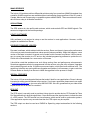
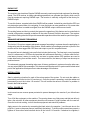
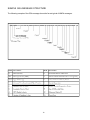
INVICTA 115
INSTALLATION AND SERVICE
MANUAL
RAVEN INDUSTRIES
205 East 6th Street
Sioux Falls, SD. 57104
Voice: 1-800-243-5435
FAX: 1-605-331-0426
www.ravenprecision.com
016-0159-912
12/02
TABLE OF CONTENTS
Introduction ...................................................................................................................................... 2
Functional Description .....................................................................................................................2
GPS Receiver ..................................................................................................................................2
WAAS Receiver ............................................................................................................................... 3
GPS Antenna ................................................................................................................................... 3
Utility Software .................................................................................................................................3
Receiver Firmware updates ............................................................................................................ 3
Special Features ..............................................................................................................................3
PPS Out .............................................................................................................................. 3
Radar Out ............................................................................................................................ 4
Advanced Message Forwarding .......................................................................................... 4
Installation ........................................................................................................................................4
Initial Power up .................................................................................................................... 4
Power .................................................................................................................................. 5
GPS Antenna ....................................................................................................................... 6
Operation .........................................................................................................................................6
Initial Startup ........................................................................................................................ 6
Normal Operation ................................................................................................................ 6
Troubleshooting ............................................................................................................................... 6
Checking your installation ....................................................................................................7
Receiver Specifications ................................................................................................................... 8
Configuration ................................................................................................................................... 8
Global Positioning System (GPS) ................................................................................................... 9
Differential GPS (DGPS) WAAS ..................................................................................................... 10
Raven Proprietary NMEA Messages ............................................................................................... 11
Sample GGA Message Structure .................................................................................................... 12
1
INTRODUCTION
The Raven Invicta 115 GPS receiver provides highly accurate and reliable DGPS navigation using
WAAS satellite based DGPS corrections. This receiver is ideal for GIS, precision farming or any other
application where a high performance, rugged, and simple to operate receiver is required.
FUNCTIONAL DESCRIPTION
The Raven Invicta 115 is a 10 channel high-performance GPS receiver with a built-in DGPS correction
receiver. Built-in WAAS receiver can be selected for DGPS corrections.
DGPS corrections are needed to improve the accuracy of standard GPS. If operated without DGPS
corrections, the accuracy will be about 4 meters RMS. This means the receiver would have an accuracy of about 12 feet in any direction 67% of the time, or about 24 feet 95% of the time. Prior to the
government turning off Selective Availability (SA), this error was 100 meters RMS. With DGPS corrections, the receiver can give positions with a RMS accuracy of 1.4 meters, about 4 feet.
Accuracy depends on many factors including the correction method and the range from source.
Primary concern with WAAS is that the Invicta 115 is designed to use this as the only source of DGPS
corrections. Considering that today there is a limited number of WAAS reference stations, the accuracy will vary from about 1 meter to 1.4 meters RMS depending on location.
In addition to improved accuracy, DGPS corrections keep the calculated position from jumping around
when the receiver loses or picks up a new satellite. Without DGPS these common occurrences will
cause the position to suddenly jump to a new point. Applications such as crop guidance will see
accuracies of about 0.75 feet RMS swath to swath when in WAAS DGPS. In this application the DGPS
correction source is critical, so the position won’t jump around while spraying a field.
For the functional description the Invicta 115 can be broken into several parts. Each is described in the
following sections.
GPS RECEIVER
The Invicta 115 GPS receiver can generate real-time position solutions at a rate of 5 solutions per
second. An option that enables the Invicta 115 to output up to 10 solutions per second can be purchased. Position solutions are output via RS232 in NMEA format messages.
The Invicta 115 has two RS232 ports and can communicate at 1200, 2400, 4800, 9600, 19.2k, or
38.4k BPS on either/both port(s). The baud rate and the desired output messages can be configured
via the serial port using configuration messages.
NMEA format messages are standard for most GPS receivers and therefore should be compatible
with almost any software or hardware application designed to work with GPS.
The receiver comes from the factory with message settings that should be compatible with most
applications. Refer to the connecting equipment manuals for information about what message types
and serial settings they require. By default, the Invicta 115 will output GGA and VTG messages on
both ports. On port A these messages are output at 19.2k BPS with 5 solutions per second. This is the
optimum setting for connecting a guidance smart bar such as the Raven LB-5. Port B will output GGA,
VTG and RMC at 4800 BPS with 1 solutions per second. This is optimum for applications such as GIS
or yield monitors.
2
WAAS RECEIVER
The Invicta 115 provides real time differential solutions using free corrections (WAAS) broadcast from
a satellite. WAAS corrections are available without a subscription free everywhere in the US, parts of
Canada, Mexico and Europe using a compatible system called EGNOS. These corrections are available 24 hours a day in all weather conditions.
GPS ANTENNA
The GPS antenna is a low profile patch antenna, which receives both GPS and WAAS signals. The
antenna is integrated in the receiver package.
UTILITY SOFTWARE
Utility software is not required to setup or use the receiver in most applications. However, a utility
program is available from Raven.
RECEIVER FIRMWARE UPDATES
Firmware is software, which resides inside the receiver. Raven continues to improve the performance
of its receiver products and sometimes makes special features available. When this happens, a new
version of firmware is created. A request can be made for this firmware from Raven. It will be necessary to connect the receiver to a PC and run the included programming software to update the unit.
Check with a Raven dealer for a new version of firmware.
It should be noted that updates cover such things as bug fixes and performance enhancements.
Sometimes upgrades can also be programmed into the receiver using the utility software. Upgrades
also include things such as the 10 solutions per second option, which does have additional cost. The
good thing is that the user can install these upgrades and updates. It will necessary to get a code from
a Raven dealer or directly from Raven to install the upgrades but the process is simple.
SPECIAL FEATURES
The Invicta 115 has several special features that make it ideal for some applications. Raven is always
interested in adding special features to the receiver. If you have a good idea, please send us an email
at [email protected] or give us a call at 800-243-5435. We can’t guarantee that your idea will be
implemented, but we do want to consider it.
PPS OUT
The PPS output is normally used to provide a timing signal to another device. PPS stands for Pulse
Per Second and that’s what the signal does. Once each second the signal pulses to indicate the start
of a GPS second. The GPS second is a time reference, which can be used to synchronize systems.
If the application requires very accurate time then the PPS output may be required.
The PPS output can also be used as a RADAR or Speed log output as described in the following
sections.
3
RADAR OUT
The receivers can simulate a Doppler RADAR commonly used on agricultural equipment for detecting
speed. The GPS receiver is always calculating speed and can generate the signals, which can be
used by equipment requiring RADAR input. The receiver is normally configured at the factory for
RADAR output.
To use this feature, a special cable from RAVEN will be needed. It should be noted that the GPS can
only determine speed when it is navigating. If a tree line blocks to many satellites or if for some other
reason the Receiver is unable to navigate, then the RADAR output could become invalid.
The scaling factors and timing controls that govern the operation of this feature can be controlled via
a serial configuration message as defined in the serial Protocol Definition document. The receiver
uses default settings that should provide reasonable operation without the need for special configuration.
ADVANCED MESSAGE FORWARDING
The Invicta 115 receiver supports advanced message forwarding in systems where the application is
designed to take full advantage of this feature. When enabled, all messages received on port B of the
receiver will be time tagged with GPS time and output on port A in a special format.
The special format is basically just a prefix that includes the time tag. The time tag is a very important
since it is referenced to GPS time and provided with millisecond resolution. It can be used to eliminate latency issues. Latency is usually only an issue in systems where GPS positions are used to
locate data coming from another sensor. If not accounted for, the latency of output can show up as
positional errors.
The advanced message forwarding takes care of latency problems in systems where the other sensor can output NMEA style messages. This feature would also be useful in systems with limited serial
ports if the application developer were to take advantage of this feature.
INSTALLATION
Start by selecting a location for each of the various parts of the system. Do not route the cables or
permanently mount the Invicta 115 receiver yet. Once the system is operating, route the cables and
permanently mount the Invicta 115 receiver. This will reduce the amount of trouble if a problem is
found in the initial locations.
INITIAL POWER UP
Invicta receivers are reverse power protected to prevent damage to the receiver if you follow these
steps:
Turn off all the equipment on the machine. The receiver draws very little power and this test will only
take a few minutes. All other equipment should be off because it might interfere with the receiver.
Once the Invicta is working, turn on the other equipment and watch for problems.
Apply power to the receiver by connecting the black wire to the negative (-) and the red wire to the
positive (+) post on the power source (most likely the battery). To check power connections connect a
lightbar or some other serial interface device to the Invicta 115 receiver. If attached to a lightbar, it
4
should light up when power is applied to the receiver. If using a serial interface device, look for NMEA
strings such as ZDA to scroll across the screen. If none of these things respond remove the red and
black wires from the power source and check the connections again. If in a car or Ag machine, try
turning the key on. If still having trouble refer to the power section below or call our technical support
line.
Once the receiver power is connected correctly go ahead and shut the power off. Mount the Invicta
115 and repeat the previous step.
At this point, the power is connected to the mounted receiver. The Invicta 115 will be looking for satellites, which may take a few minutes. Eventually, if the antenna has a clear view of the sky, the receiver
will send data to the lightbar or other serial interface devise.
Wait for the receiver to find and track the WAAS signal, it could take 15 or more minutes before the
receiver gets the necessary almanac data from the selected WAAS satellite. This initial startup time is
necessary only during the first time the receiver is used. Once the broadcast is found the receiver will
power up and start receiving signals after about 5 seconds. If a signal is not received within about 30
minutes there could be some form of interference or the receiver may not be in the coverage area of
the selected WAAS satellite.
At this point, the receiver should be tracking satellites and generating good differential position. Start
tuning on other equipment on the machine. A device could interfere with the GPS satellites or WAAS
signals. Wait about 30 seconds after each device is turned on to see if the receiver stops tracking
satellites. Finally, start up the machine and again watch for any problems.
If after turning something on, a problem is found, try moving the antenna further away from that device.
Check that the device is functioning properly and also check its power connections. Some devices
can generate too much noise naturally or because of defective components.
Now the receiver is working with everything that could interfere. Shut everything off, mount the receiver, and route the cables. Once this is done, repeat the power up steps.
The last few steps deal with connecting the other equipment that gets data from the Invicta 115. Refer
to the manufacturer’s documentation for details such as baud rates and required messages. It is very
likely it will only be necessary to connect the interface cables to the device. The Invicta 115 is configured, by default, to work with most systems without any adjustments.
All configuration and WAAS data is stored in non-volatile memory inside the Invicta 115. If it is necessary to change the WAAS or GPS setups, run the receiver software to make the changes.
POWER
The Invicta 115 receiver needs DC power between 9 and 16 Volts. DC power is usually provided by
battery on the machine or via a power adapter of some type. If the unit came with an automotive
power adapter, verify that the vehicle has a negative ground system before connecting power. If the
unit came with an AC adapter, it will be necessary to only connect the adapter to an AC source.
5
GPS ANTENNA
GPS is a line of sight system, which means in order for the receiver to track the satellites there must
be an unobstructed path directly to them. Buildings, trees, machinery, and human bodies are common
obstructions. When locating the antenna/receiver find a place where the antenna will have an unobstructed view of the sky. Items such as electrical motors, generators, alternators, strobe lights, radio
transmitters, cellular phones, microwave dishes, radar, active antennas, etc., all generate electrical
and magnetic fields which can interfere with the GPS or WAAS signal. Mount the Antenna/receiver
away from such potential sources of interference.
The GPS can be de-tuned by close proximity to other objects. For example, if you place the antenna
under fiberglass its performance could be degraded. Usually, if the antenna/receiver is lowered so that
at least a quarter of an inch gap is made between the antenna/receiver and the covering plastic or
fiberglass, acceptable performance can be achieved. Metal or other dense materials will completely
block the GPS signals.
OPERATION
Initial startup
Both the internal GPS and WAAS receiver must perform a COLD START the first time the system is
powered up. The GPS receiver will search the sky for satellites and download data necessary for
operation. The WAAS receiver will wait until the required almanac data is received. The cold start will
take up to 15 minutes but is only required during the initial power up.
Connect the serial cable provided between the Invicta 115 and the computer, apply power. Allow the
receiver to operate while installing the software program on the computer. Turn off all unnecessary
electrical equipment to minimize electrical noise interference.
NORMAL OPERATION
Upon completion of the initial “cold start”, the receiver begins to operate in “normal mode”. The unit
should be operating in full DGPS mode within a few minutes of power up.
All configuration and WAAS data is stored in nonvolatile memory inside the Invicta 115. Configuration
changes are made with utility software.
Be aware of possible satellite obstructions, which may interfere with GPS operation.
TROUBLESHOOTING
·
Make sure the antenna is mounted so that it has a clear view of the sky and is as far away from
electrical noise sources as possible.
Attempt to isolate all problems as either:
· Receiver/Antenna
· Power
· Transmitting Site
· Serial Communications
· Peripheral Device
6
CHECKING YOUR INSTALLATION
Monitor the effects on the beacon and GPS receiver performance as each devise on the vehicle is
powered on. If the receiver stops operating properly when a device is powered on, that device is
causing interference and the receiver location may need to change. For example, if running the engine
causes interference, then ignition noise or alternator noise is interfering with signal reception. Move
the receiver further away from the engine.
Receiver – Normally only 5GPS satellites are required for good accuracy. If a lightbar is connected,
ensure the 3 center LED’S are lit green.
Transmitting – If the receiver is operating in WAAS Mode, the receiver may be out of range of a satellite
or the Satellite may be off the air. WAAS status information is available on the Internet at
WWW.FAA…..
Serial Coms – Using GPS MON software, check for proper communication settings baud rate, and
COM Port number. Make sure the cable used, if not provided by raven, is wired
correctly. See section titled “serial Interface”.
7
RECEIVER SPECIFICATIONS
Size
7.63” x 4.13” x 1.75”
Protocols
NMEA v2.2
Weight
20 ounces
Position Accuracy
50 meter RMS, SA on
Operating Temperature
-40°C to +70°C
4 meter RMS, SA off
Operating Humidity
5% to 95% R.H.,
1.4 meter RMS, WAAS DGPS
Non-condensing, at +60°C
Channels
Update Rate
10 GPS, 1 WAAS
5/second
Mounting
Magnetic
(10/second optionally)
Power Consumption
4 Watts Typical
Operating Temp.
-40°C to +85°C
Voltage
9-16 VDC
Operating Humid.
100% Condensing
CONFIGURATION
“SERIAL INTERFACE”
The Invicta 115 has two bi-directional RS232 serial interfaces available on a single external DB9
female connector. Each port is assigned a single letter in uppercase, ‘A’ or ‘B’ and each one provides
the necessary interfacing between the Invicta 115 and your navigation equipment.
DB9-F
Port A
Signal Name
1
RAD/PPS
2
Port “A” TX
3
Port “A” RX
4
Port “B” RX
5
GND
6
Port “B” TX
7
No connect
8
+12 VDC Pwr Output
9
GND
8
GLOBAL POSITIONING SYSTEM (GPS)
GPS is a satellite-based global navigation system created and operated by the United States Department
of Defense (DOD). Originally intended solely to enhance military defense capabilities, GPS capabilities
have expanded to provide highly accurate position and timing information for many civilian applications.
An in-depth study of GPS is required to fully understand it, but not to see how it works or appreciate
what it can do for you. Simply stated, twenty-four satellites in six orbital paths circle the earth twice
each day at an inclination angle of approximately 55 degrees to the equator. This constellation of
satellites continuously transmits coded positional and timing information at high frequencies in the
1500 Megahertz range. GPS receivers with antennas located in a position to clearly view the satellites
pick up these signals and use the coded information to calculate a position in an earth coordinate
system.
GPS is the navigation system of choice for today and many years to come. While GPS is clearly the
most accurate worldwide all-weather navigation system yet developed, it still can exhibit significant
errors. GPS receivers determine position by calculating the time it takes for the radio signals transmitted
from each satellite to reach earth. It’s that old “Distance = Rate x Time” equation. Radio waves travel
at the speed of light (Rate). Time is determined using an ingenious code matching technique within
the GPS receiver. With time determined, and the fact that the satellite’s position is reported in each
coded navigation message, by using a little trigonometry the receiver can determine its location on
earth.
Position accuracy depends on the receiver’s ability to accurately calculate the time it takes for each
satellite signal to travel to earth. This is where the problem lies. There are primarily five sources of
errors, which can affect the receiver’s calculation. These errors consist of:
1.
Ionosphere and troposphere delays on the radio signal.
2.
Signal multi-path.
3.
Receiver clock biases.
4.
Orbital satellite (ephemeris) position errors.
5.
Intentional degradation of the satellite signal by the DOD (SA).
This intentional degradation of the signal is known as “Selective Availability” (SA) and is intended to
prevent adversaries from exploiting highly accurate GPS signals and using them against the United
States or its allies. SA accounts for the majority of the error budget. The combination of these errors
in conjunction with poor satellite geometry can limit GPS accuracy to 100 meters 95% of the time and
up to 300 meters 5% of the time. Fortunately, many of these errors can be reduced or eliminated
through a technique known as “Differential.”
9
DIFFERENTIAL GPS (DGPS) WAAS
DGPS works by placing a high-performance GPS receiver (reference station) at a known location.
Since the receiver knows its exact location, it can determine the errors in the satellite signals. It does
this by measuring the ranges to each satellite using the signals received and comparing these measured
ranges to the actual ranges calculated from its known position. The difference between the measured
and calculated range is the total error. The error data for each tracked satellite is formatted into a
correction message and transmitted to GPS users. The correction message format follows the
standard established by the Radio Technical Commission for Maritime Services, Special Committee
104 (RTCM-SC104). These differential corrections are then applied to the GPS calculations, thus
removing most of the satellite signal error and improving accuracy. The level of accuracy obtained is
a function of the GPS receiver. WAAS is based on a network of approximately 25 ground reference
stations that cover a very large service area. Signals from GPS satellites are received by wide area
ground reference stations and used to generate DGPS corrections.
Differential GPS Broadcast Site
10
NMEA MESSAGES
The Invicta 115 receiver can be used to communicate with other electronic devices including Raven’s
RGL 500 Swath Guidance Light bar. A communication protocol (set of rules) known as the NMEA 0183
standard has been established by the National Marine Electronics Association. The NMEA 0183
standard contains numerous message formats such as the ones described below which the Invicta
115 receiver uses to communicate with other devices.
RPR 110 NMEA Messages
ALM
GPS Almanac Data
DTM
Datum Reference
GGA
Global Positioning System Fix Data
GLL
Geographic Position
GRS
GPS Range Residuals
GSA
GPS Dillution of Precision (DOP) and Active Satellites
GST
GPS Pseudorange Noise Statistics
GSV
GPS Satellites in View
MSK
MSK Receiver Interface
MSS
MSK Signal Status
RMC
Recommended Minimum specific GPS/Transit Data
VTG
Course Over Ground and Ground Speed
ZDA
Time and Date
PROPRIETARY NMEA MESSAGES
SLIB1S
SLIB2S
SLIDIF
SLIE1S
SLIRTC
SLISDA
SLISOL
SLIWRN
Beacon Receiver Channel 1 Status
Beacon Receiver Channel 2 Status
DGPS Status Information
External RTCM Channel 1 Status
RTCM Message Data Received
Satellite Age of Data
Position Solution
Receiver Warning Message
11
SAMPLE GGA MESSAGE STRUCTURE
The following example of the GGA message shows the format typical of NMEA messages.
12
RAVEN INDUSTRIES
LIMITED WARRANTY
WHAT IS COVERED?
This warranty covers all defects in workmanship or materials in your
Raven Flow Control Product under normal use, maintenance, and
service.
HOW LONG IS THE COVERAGE PERIOD?
This warranty coverage runs for 12 months from the purchase date of
your Raven Flow Control Product. This warranty coverage applies only
to the original owner and is not transferrable.
HOW CAN YOU GET SERVICE?
Bring the defective part, and proof of date of purchase, to your local
dealer. If your dealer agrees with the warranty claim, he will send the
part, and proof of purchase to his distributor or to Raven for final approval.
WHAT WILL RAVEN INDUSTRIES DO?
When our inspection proves the warranty claim, we will, at our option,
repair or replace the defective part and pay for return freight.
WHAT DOES THIS WARRANTY NOT COVER?
Raven Industries will not assume any expense or liability for repairs made
outside our plant without written consent. We are not responsible for
damage to any associated equipment or product and will not be liable
for loss of profit or other special damages. The obligation of this warranty
is in lieu of all other warranties, expressed or implied, and no person is
authorized to assume for us any liability. Damages caused by normal
wear and tear, mis-use, abuse, neglect, accident, or improper installation
and maintenance are not covered by this warranty.
Manual Rev. A, Invicta 115,
12/02
#016-0159-912