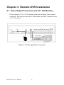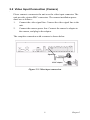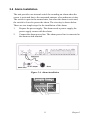
1
DVR-530 16 Channel Standalone Network & USB DVR User’s Manual Copyright The documentation and the software included with this product are copyrighted 2005 by Advantech Co., Ltd. All rights are reserved. Advantech Co., Ltd. reserves the right to make improvements in the products described in this manual at any time without notice. No part of this manual may be reproduced, copied, translated or transmitted in any form or by any means without the prior written permission of Advantech Co., Ltd. Information provided in this manual is intended to be accurate and reliable. However, Advantech Co., Ltd. assumes no responsibility for its use, nor for any infringements of the rights of third parties, which may result from its use. Acknowledgements Intel and Pentium are trademarks of Intel Corporation. Microsoft Windows and MS-DOS are registered trademarks of Microsoft Corp. All other product names or trademarks are properties of their respective owners. 1st Edition Printed in Taiwan DVR-530 User’s Manual August 2005 ii Product Warranty (1 year) Advantech warrants to you, the original purchaser, that each of its products will be free from defects in materials and workmanship for one year from the date of purchase. This warranty does not apply to any products which have been repaired or altered by persons other than repair personnel authorized by Advantech, or which have been subject to misuse, abuse, accident or improper installation. Advantech assumes no liability under the terms of this warranty as a consequence of such events. Because of Advantech’s high quality-control standards and rigorous testing, most of our customers never need to use our repair service. If an Advantech product is defective, it will be repaired or replaced at no charge during the warranty period. For out-of-warranty repairs, you will be billed according to the cost of replacement materials, service time and freight. Please consult your dealer for more details. If you think you have a defective product, follow these steps: 1. Collect all the information about the problem encountered. (For example, CPU speed, Advantech products used, other hardware and software used, etc.) Note anything abnormal and list any onscreen messages you get when the problem occurs. 2. Call your dealer and describe the problem. Please have your manual, product, and any helpful information readily available. 3. If your product is diagnosed as defective, obtain an RMA (return merchandize authorization) number from your dealer. This allows us to process your return more quickly. 4. Carefully pack the defective product, a fully-completed Repair and Replacement Order Card and a photocopy proof of purchase date (such as your sales receipt) in a shippable container. A product returned without proof of the purchase date is not eligible for warranty service. 5. Write the RMA number visibly on the outside of the package and ship it prepaid to your dealer. iii Declaration of Conformity CE This product has passed the CE test for environmental specifications when shielded cables are used for external wiring. We recommend the use of shielded cables. This kind of cable is available from Advantech. Please contact your local supplier for ordering information. CE This product has passed the CE test for environmental specifications. Test conditions for passing included the equipment being operated within an industrial enclosure. In order to protect the product from being damaged by ESD (Electrostatic Discharge) and EMI leakage, we strongly recommend the use of CE-compliant industrial enclosure products. FCC Class A This equipment has been tested and found to comply with the limits for a Class A digital device, pursuant to part 15 of the FCC Rules. These limits are designed to provide reasonable protection against harmful interference when the equipment is operated in a commercial environment. This equipment generates, uses, and can radiate radio frequency energy and, if not installed and used in accordance with the instruction manual, may cause harmful interference to radio communications. Operation of this equipment in a residential area is likely to cause harmful interference in which case the user will be required to correct the interference at his own expense. DVR-530 User’s Manual iv Technical Support and Assistance 1. Visit the Advantech web site at www.advantech.com/support where you can find the latest information about the product. 2. Contact your distributor, sales representative, or Advantech's customer service center for technical support if you need additional assistance. Please have the following information ready before you call: - Product name and serial number - Description of your peripheral attachments - Description of your software (operating system, version, appliction software, etc.) - A complete description of the problem - The exact wording of any error messages Document Feedback To assist us in making improvements to this manual, we would welcome comments and constructive criticism. Please send all such comments in writing to: [email protected] Packing List Before setting up the system, check that the items listed below are included and in good condition. If any item does not accord with the table, please contact your dealer immediately. • 1 x power cord • 1 x user manual • 1 x CD for PC client software Safety Instructions 1. Read these safety instructions carefully. 2. Keep this User's Manual for later reference. 3. Disconnect this equipment from any AC outlet before cleaning. Use a damp cloth. Do not use liquid or spray detergents for cleaning. v 4. For plug-in equipment, the power outlet socket must be located near the equipment and must be easily accessible. 5. Keep this equipment away from humidity. 6. Put this equipment on a reliable surface during installation. Dropping it or letting it fall may cause damage. 7. The openings on the enclosure are for air convection. Protect the equipment from overheating. DO NOT COVER THE OPENINGS. 8. Make sure the voltage of the power source is correct before connecting the equipment to the power outlet. 9. Position the power cord so that people cannot step on it. Do not place anything over the power cord. 10. All cautions and warnings on the equipment should be noted. 11. If the equipment is not used for a long time, disconnect it from the power source to avoid damage by transient overvoltage. 12. Never pour any liquid into an opening. This may cause fire or electrical shock. 13. Never open the equipment. For safety reasons, the equipment should be opened only by qualified service personnel. 14. If one of the following situations arises, get the equipment checked by service personnel: a. The power cord or plug is damaged. b. Liquid has penetrated into the equipment. c. The equipment has been exposed to moisture. d. The equipment does not work well, or you cannot get it to work according to the user's manual. e. The equipment has been dropped and damaged. f. The equipment has obvious signs of breakage. 15. DO NOT LEAVE THIS EQUIPMENT IN AN ENVIRONMENT WHERE THE STORAGE TEMPERATURE MAY GO BELOW 20° C (-4° F) OR ABOVE 60° C (140° F). THIS COULD DAMAGE THE EQUIPMENT. THE EQUIPMENT SHOULD BE IN A CONTROLLED ENVIRONMENT. 16. CAUTION: DANGER OF EXPLOSION IF BATTERY IS INCORRECTLY REPLACED. REPLACE ONLY WITH THE SAME OR EQUIVALENT TYPE RECOMMENDED BY THE DVR-530 User’s Manual vi MANUFACTURER, DISCARD USED BATTERIES ACCORDING TO THE MANUFACTURER'S INSTRUCTIONS. The sound pressure level at the operator's position according to IEC 7041:1982 is no more than 70 dB (A). DISCLAIMER: This set of instructions is given according to IEC 704-1. Advantech disclaims all responsibility for the accuracy of any statements contained herein. Wichtige Sicherheishinweise 1. Bitte lesen sie Sich diese Hinweise sorgfältig durch. 2. Heben Sie diese Anleitung für den späteren Gebrauch auf. 3. Vor jedem Reinigen ist das Gerät vom Stromnetz zu trennen. Verwenden Sie Keine Flüssig-oder Aerosolreiniger. Am besten dient ein angefeuchtetes Tuch zur Reinigung. 4. Die NetzanschluBsteckdose soll nahe dem Gerät angebracht und leicht zugänglich sein. 5. Das Gerät ist vor Feuchtigkeit zu schützen. 6. Bei der Aufstellung des Gerätes ist auf sicheren Stand zu achten. Ein Kippen oder Fallen könnte Verletzungen hervorrufen. 7. Die Belüftungsöffnungen dienen zur Luftzirkulation die das Gerät vor überhitzung schützt. Sorgen Sie dafür, daB diese Öffnungen nicht abgedeckt werden. 8. Beachten Sie beim. AnschluB an das Stromnetz die AnschluBwerte. 9. Verlegen Sie die NetzanschluBleitung so, daB niemand darüber fallen kann. Es sollte auch nichts auf der Leitung abgestellt werden. 10. Alle Hinweise und Warnungen die sich am Geräten befinden sind zu beachten. 11. Wird das Gerät über einen längeren Zeitraum nicht benutzt, sollten Sie es vom Stromnetz trennen. Somit wird im Falle einer Überspannung eine Beschädigung vermieden. 12. Durch die Lüftungsöffnungen dürfen niemals Gegenstände oder Flüssigkeiten in das Gerät gelangen. Dies könnte einen Brand bzw. elektrischen Schlag auslösen. vii 13. Öffnen Sie niemals das Gerät. Das Gerät darf aus Gründen der elektrischen Sicherheit nur von authorisiertem Servicepersonal geöffnet werden. 14. Wenn folgende Situationen auftreten ist das Gerät vom Stromnetz zu trennen und von einer qualifizierten Servicestelle zu überprüfen: a - Netzkabel oder Netzstecker sind beschädigt. b - Flüssigkeit ist in das Gerät eingedrungen. c - Das Gerät war Feuchtigkeit ausgesetzt. d - Wenn das Gerät nicht der Bedienungsanleitung entsprechend funktioniert oder Sie mit Hilfe dieser Anleitung keine Verbesserung erzielen. e - Das Gerät ist gefallen und/oder das Gehäuse ist beschädigt. f - Wenn das Gerät deutliche Anzeichen eines Defektes aufweist. 15. VOSICHT: Explisionsgefahr bei unsachgemaben Austausch der Batterie.Ersatz nur durch densellben order einem vom Hersteller empfohlene-mahnlichen Typ. Entsorgung gebrauchter Batterien navh Angaben des Herstellers. 16. ACHTUNG: Es besteht die Explosionsgefahr, falls die Batterie auf nicht fach-männische Weise gewechselt wird. Verfangen Sie die Batterie nur gleicher oder entsprechender Type, wie vom Hersteller empfohlen. Entsorgen Sie Batterien nach Anweisung des Herstellers. Der arbeitsplatzbezogene Schalldruckpegel nach DIN 45 635 Teil 1000 beträgt 70 dB(A) oder weiger. Haftungsausschluss: Die Bedienungsanleitungen wurden entsprechend der IEC-704-1 erstellt. Advantech lehnt jegliche Verantwortung für die Richtigkeit der in diesem Zusammenhang getätigten Aussagen ab. DVR-530 User’s Manual viii Safety Precaution - Static Electricity Follow these simple precautions to protect yourself from harm and the products from damage. 1. To avoid electrical shock, always disconnect the power from your PC chassis before you work on it. Don't touch any components on the CPU card or other cards while the PC is on. 2. Disconnect power before making any configuration changes. The sudden rush of power as you connect a jumper or install a card may damage sensitive electronic components. Safety Information and Technical Specifications Electrical Safety Guidelines Checking the Power Cords Warning!: To avoid electrical shock, check the power cords as follows: • Use the exact type of power cords as required. • Be sure to use power cord(s) that came with safety certifications. • The power cord(s) must be compliant with the AC voltage requirements in your region. • The power cord plug cap must have an electrical current rating that is at least 125% of the electrical current rating of this product. • The power cord plug cap that plugs into the AC receptacle on the power supply must be an IEC 320, sheet C13, type female connector. • Be sure to disconnect the power supply before accessing the DVR series or its components. • Plug the Power cord(s) into a socket that is properly grounded before turning on the power. ix General Electrical Safety Guidelines Warning!: Follow the guidelines below to avoid possible damages to the system or injury to yourself: • Be aware of the locations of the power switches on the chassis and in the room, so you can disconnect the power supply if an accident occurs. • Take extra precautionary measures when working with high voltage components. It is not recommended to work alone. • Before removing or installing main system components, be sure to disconnect the power first. Turn off the system before you disconnect the power supply. • Use only one hand when working with powered-on electrical equipment to avoid possible electrical shock. • Use rubber mats specifically designed as electrical insulators when working with computer systems. • The power supply or power cord must include a grounding plug and must be plugged into grounded outlets. • Motherboard Battery: CAUTION - Make sure not to install the onboard battery upside down to avoid possible explosion. Make sure that the positive side is facing up on the motherboard. This battery must be replaced only with the same or an equivalent type recommended by the manufacturer. Dispose of used batteries according to the manufacturer's instructions. • CD-ROM Laser: CAUTION - Do not open the enclosures of power supplies or CD ROMs to avoid injury. DVR-530 User’s Manual x General Safety Guidelines Warning!: Follow these rules to ensure general safety: • Keep the area around the DVR series clean and free of clutter. • To avoid injuries to the back, be sure to use your leg muscles, keep your back straight, and bend your knees, when lifting the system. • Avoid wearing loose clothing to preventing it from coming into contact with electrical circuits or being pulled into a cooling fan. • After removing the components or chassis covers from the system, place them on a table for safeguard. • Be sure to remove any jewelry or metal objects before working on the chassis to avoid short circuits should these objects come into contact with power circuits. • After accessing the interior of the chassis, be sure to close the chassis with chassis covers and secure the chassis to the racks with screws. xi DVR-530 User’s Manual xii Contents Chapter 1 DVR-530 Introduction .................................... 2 1.1 1.2 1.3 Chapter Chapter 2 Remote DVR Installation ............................... 8 2.1 Video Output Connection (TV Or LCD Monitor) ............ 8 2.2 Video Input Connection (Camera) .................................... 9 2.3 Sensor Installation ........................................................... 10 2.4 Alarm Installation............................................................ 11 Figure 2.1:Video signal line connection ........................ 8 Figure 2.2:Video input connection ................................ 9 Figure 2.3:Sensor installation ...................................... 10 Figure 2.4:Alarm installation ....................................... 11 3 Powering Up the Unit.................................... 14 3.1 Chapter Front Panel ........................................................................ 3 Remote IR Controller ........................................................ 4 Rear Panel ......................................................................... 5 On-Screen Display .......................................................... 14 Figure 3.1:HDD Checking in progress ........................ 14 Figure 3.2:Real Time Display Mode ........................... 14 Figure 3.3:Powering on the system .............................. 16 4 Operation Guide............................................ 18 4.1 4.2 4.3 4.4 4.5 4.6 4.7 Main Menu ...................................................................... 18 Group Select.................................................................... 19 Record Select................................................................... 20 Record Frame Rate.......................................................... 20 Video Quality .................................................................. 21 Record Schedule.............................................................. 22 Sub Menu ........................................................................ 23 4.8 4.9 4.10 4.11 4.12 4.13 4.14 4.15 Time Set .......................................................................... 24 Backup Through USB Port ............................................. 25 Group Display Time........................................................ 26 Hard Disk Setup .............................................................. 27 Sensor Setup.................................................................... 28 How to Operate Motion Detection Recording ................ 29 Network Setup................................................................. 30 Playback .......................................................................... 31 Table 4.1:Front panel button definitions ...................... 23 Appendix A Networking..................................................... 34 Figure A.1:Main Window of PC Client Software ....... 34 A.1 A.2 A.3 Connect PC to the DVR .................................................. 35 DVR Control ................................................................... 38 Capture and Playback on your PC................................... 39 A.3.1 A.3.2 Capture Video Data ..................................................... 39 Playback ....................................................................... 39 xiii Table of Contents A.4 A.5 A.6 A.7 DVR Management........................................................... 40 AVI File........................................................................... 41 Channel Control .............................................................. 42 Single Channel Scaler ..................................................... 43 Appendix B PC Viewer ...................................................... 46 B.1 Installing PC Viewer ....................................................... 46 B.2 B.3 Searching Files ................................................................ 50 Backing up files as AVI .................................................. 51 Table B.1:Playback buttons ......................................... 47 Appendix C Video Quality Settings Table........................ 54 C.1 NTSC Format ................................ 54 C.2 PAL Format.................................. 55 DVR-530 User’s Manual Table C.1:Recording time vs. video quality (NTSC) .. 54 Table C.2:Recording time vs. video quality (PAL) ..... 55 xiv CHAPTER 1 2 DVR-530 Introduction This section introduces the DVR-530 Digital Video Recorder (DVR). This section includes: • Front Panel • Remote IR Controller • Rear Panel Chapter 1 DVR-530 Introduction The DVR-530 digital video recorder (DVR) is for recording/retrieving video streams from up to 16 channels at the same time. It adopts a digital image compression technology to compress the input channel video streams, and uses a HDD to record the compressed video stream. This user manual explains how to install, operate, and manage the DVR in your home. Hope you enjoy it and find it useful to protect your home or office. DVR-530 User’s Manual 2 1.1 Front Panel 6 5 4 3 13 1 7 12 8 9 11 2 15 14 10 1. Menu button: press to display Operation menu option 2. z Recording button: press to start recording 3. Stop recording/playback button: press to stop recording/playback the authorized password is requested upon stopping record (the defaut password is 111111) 4. Fast forward button: press to play the recorded video stream faster 5. f Playback button/Pause button: press to start playback and press to pause the video playback 6. Pause button: press to pause the video playback 7. Reverse: press to play backwards 8. Group 1 button: press to select group 1 9. Group 2 button: press to select group 2 10. Group 3 button: press to select group 3 11. Group 4 button: press to select group 4 12. 田 All groups button: press to select all groups display 13. 14. Up button: press to change menu field 15. Select button: press to change the setting value or enter a sub menu Down down buttons: press to change menu field 3 Chapter 1 1.2 Remote IR Controller 9 12 3 10 8 11 2 7 6 4 5 14 13 15 1 1. 2. 3. z Menu button: press to display Operation menu option Recording button: press to start recording Stop recording/playback button: press to stop recording/playback-the authorized password is requested upon stopping record (the defaut password is 111111) 4. Fast forward button: press to play the recorded video stream faster. 5. f Playback button/Pause button: press to start playback and press to pause the video playback 6. Pause button: press to pause the video playback 7. 8. 9. 10. 11. Reverse: press to play backwards Group 1 button: press to select group 1 Group 2 button: press to select group 2 Group 3 button: press to select group 3 Group 4 button: press to select group 4 12. 田 All groups button: press to select all groups display 13. 14. Up buttons: press to change menu field Down button: press to change menu field 15. Select button: press to change the setting value or enter a sub menu DVR-530 User’s Manual 4 1.3 Rear Panel 1. S-Video 2. Video output 3. VGA output 4. Video input 5. Video Quad loop-through 6. Sensor input/alarm output: 4 sensor inputs and one alarm output 7. NTSC/PAL switch 8. DC-in (12 Volts) 9. Audio input/output 10. LAN 11. Power switch 5 Chapter 1 DVR-530 User’s Manual 6 CHAPTER 2 2 DVR Installation This section explains the installation of the DVR-530 Digital Video Recorder (DVR). This section includes: • Video Output Connection • Video Input Connection • Sensor Installation • Alarm Installation Chapter 2 Remote DVR Installation 2.1 Video Output Connection (TV Or LCD Monitor) Please connect a TV or LCD monitor to the unit with the Video output connector. The unit provides one S-Video input, two BNC connectors and one VGA output. Figure 2.1: Video signal line connection DVR-530 User’s Manual 8 2.2 Video Input Connection (Camera) Please connect a camera to the unit over the video input connector. The unit provides sixteen BNC connectors. The camera installation procedures are as follows: 1. Connect the video signal line: Connect the video signal line to the unit. 2. Connect the camera power line: Connect the camera’s adaptor to the camera, and plug in the adaptor. The complete connection with a camera is shown below. Figure 2.2: Video input connection 9 Chapter 2 2.3 Sensor Installation The unit provides four sensor inputs for four channels. The sensor installation is as follows. The maximum power requirement of the sensor device is up to 1.5 V @ 50 mA. 1. Connect the sensor signal line: Connect the video signal line to the unit. The sensor signal terminal is at the unit’s back panel. 2. Connect the sensor power adaptor jack into the sensor, and plug in the adaptor. Figure 2.3: Sensor installation DVR-530 User’s Manual 10 2.4 Alarm Installation The unit provides one internal switch for sounding an alarm when the sensor is activated due to the unwanted entrance of an unknown visitor. The switch is open in the normal state, but when the alarm is activated, the switch is closed to power the alarm. The circuitry is shown below. There are two simple steps for the installation of the alarm. 1. Prepare the power supply: The alarm needs a power supply, the power supply comes with the alarm. 2. Connect the alarm power line: The alarm power line is connected to the alarm switch terminal. Figure 2.4: Alarm installation 11 Chapter 2 DVR-530 User’s Manual 12 CHAPTER 3 2 Powering Up the Unit This section shows the power up screens of the Digital Video Recorder (DVR). This section includes: • On-screen display Chapter 3 Powering Up the Unit 3.1 On-Screen Display After the unit is properly installed it is ready to record and play. Apply power and switch on. Note: Make sure the HDD is powered off before removing the drive After the unit is powered on, the unit checks the HDD for several seconds, then displays the following screen. Figure 3.1: HDD Checking in progress Figure 3.2: Real Time Display Mode The unit will enter into real-time display mode as shown above. DVR-530 User’s Manual 14 Notes: 1. Make sure the HDD is off before removing the drive. 2. Once you resume the initial setting, the right information will be displayed on the screen. Turn off the unit and restart. 15 Chapter 3 On-Screen Display (OSD) Figure 3.3: Powering on the system DVR-530 User’s Manual 16 CHAPTER 4 2 Operation Guide This section explains the operation of the DVR-530 Digital Video Recorder (DVR). This section includes: • Main Menu • Group Select • Record Select • Record Frame Rate • Video Quality • Record Schedule • Sub Menu • Time Set • Backup Through USB Port • Group Display Time • Hard Disk Setup • Sensor Setup • Motion Detection Recording • Network Setup • Playback Chapter 4 Operation Guide 4.1 Main Menu Press to display menu Operation Buttons press to display menu. press to change menu field or change the unit’s configuration values. press to select menu item or confirm the selection. Note: Please stop recording or playback before you enter the OSD menu. You will be requested to enter a password to stop recording. DVR-530 User’s Manual 18 4.2 Group Select The unit provides sixteen camera inputs. Every four channels are grouped for easy and prompt display operation. For example, Ch 1, Ch 2, Ch 3 and Ch 4 are set for Group 1; Ch 5, Ch 6, Ch 7 and Ch 8 are for Group 2 and so on. MAIN MENU ¾ GROUP SELECT 1234 RECORD SELECT 1234 RECORD FRAMERATE 30 VIDEO QUALITY HI RECORD SCHEDULE SUB MENU HARD DRIVE SETUP SENSOR SETUP NETWORK SETUP The unit provides 4 camera inputs. You can use channel buttons on the front panel to select a specified channel for real-time display. You can use the button or channel buttons for different combinations of channel display. Example: 1. When you choose (----), all cameras are off. 2. When you choose (1234), all cameras are displayed. 3. When you choose (---4), only the fourth channel is displayed. Note: The VIDEO LOSS signal will be displayed and the built-in alarm buzzer will sound for video connection signal loss or connection failure. 19 Chapter 4 4.3 Record Select Selecting a group on this menu option is the same as selecting the “Group Select” option. Only the selected group will record real-time events during the recording period. MAIN MENU GROUP SELECT 1234 ¾RECORD SELECT 1234 RECORD FRAMERATE 30 VIDEO QUALITY HI RECORD SCHEDULE SUB MENU HARD DRIVE SETUP 4.4 Record Frame Rate There are five different frame rate settings for operation: 25 fps, 12 fps, 8 fps, 6 fps, and 4 fps. The unit is set to 25 fps at the factory. Please use the buttons on the front panel to select the mode and the button to confirm the selection. Note: Recording Frame Rate: The higher the record frame rate, the more natural the look will be displayed on the screen in playback mode. The lower the record frame rate is, the less space will be used on the HDD. DVR-530 User’s Manual 20 4.5 Video Quality There are three different video quality settings for operation: Normal, Low, and High. Please use the buttons on the front panel to select a mode and then enter to confirm the selection The higher the video quality is, the more clear the image will be. With lower video quality, less space is used on the HDD. You can refer to Appendix C for the recording time vs. video quality settings table for your reference. 21 Chapter 4 4.6 Record Schedule Enter this option to change a recording schedule during a day (24-hour period). Numbers above indicate the time duration of 24 hours. (T) Letter indicates recording. (S) Letter indicates sensor recording. This means the unit starts recording when the attached sensors are triggered during this period. (--) Recording is off for this duration. SETTING EXAMPLE: 0:00 ~ 7:00 SENSOR RECORDING 7:00 ~ 11:00 RECORDING DISABLED 11:00 ~ 18:00 RECORDING 18:00 ~ 24:00 SENSOR RECORDING +SSSSSS----T T T T T T T S S S S S S + : : : : : 0 6 11 18 24 Note: Sensor Recording Installation: The unit provides four alarm inputs which can be configured as normally closed, normally open, motion detection + NC and motion detection + NO in the “SENSOR SETUP” menu option. After sensor configuration, please go back to the “RECORD SCHEDULE” menu to enable sensor recording. DVR-530 User’s Manual 22 4.7 Sub Menu Enter into this option to change password, time /date settings, and date format. Password Change When you enter into “PASSWORD CHANGE”, a password change input menu replaces the “SUB MENU” (The default password is 111111). When the new password is accepted, the board will flash the following screen message: PASSWORD changed!! The message will blink 5 times. Then the display goes back to the “SUB MENU”. If the password was not accepted, the unit will automatically return to “SUB MENU”. Table 4.1: Front panel button definitions 田 means “5” f means “B” means “2” z means “6” means “C” means “3” means “7” means “D” means “4” means “8” means “E” means “F” means “9” means “1” means “0” 23 Chapter 4 Time Set Enter this option to change the date and time. The unit provides yyyy/mm/dd or dd/mm/yyyy variants which reflect regional preferences. DVR-530 User’s Manual 24 4.8 Backup Through USB Port The unit provides one USB port for simple backup over a connection with a PC. Please use the following steps to successfully link: 1. Connect the USB cable between the unit and PC. 2. Select “LINK TO PC” under the submenu of the unit. The “linking” will take around 30 seconds. The connection is then ready for PC backup as “Linked” is indicated on the screen. 3. Open the PC viewer on the PC after the PC identifies the unknown hardware device. 4. Press the ”Menu” button to go back to the “Main Menu.” Note: 1. The unit employs USB 2.0, so it will take around 5 min to handshake with USB 1.0. 2. Before performing a backup over USB, please install the PC Viewer software on your PC. 25 Chapter 4 Warning!: Please don’t press the “MENU” button during linking, it could lead to an unpredictable error on your PC. Note: Please refer to Appendix C for the PC viewer installation and operation guide. 4.9 Group Display Time Use this menu to specify group display and multi-screen dwell time. Dwell time settings determine the time interval between displays for all groups and multi-screens. DVR-530 User’s Manual 26 4.10 Hard Disk Setup HARD DRIVE SETUP OVERWRITE ENABLED YES MASTER HDD SIZE 40000MB MASTER HDD USED 0MB 0% MASTER HDD FORMAT SLAVE HDD SIZE PRESS (¿À), THEN ( ) PRESS() TO EXIT Overwrite Enabled: If you choose “YES”, the unit will continue recording and overwrite the recorded data when the HDD’s space is full. If you choose “NO”, the unit will stop recording when the HDD’s space is full. Master HDD Size: Indicates the capacity of the primary HDD installed in the unit. Master HDD Used: Indicates the percentage of the HDD’s capacity used. Master HDD Format: Erases all recorded data in the Master HDD. The authorized password is requested before formatting. After the unit is formatted, the following message will appear on the screen: “HARD DISK FORMATTED”. Note: The unit is featured with one HDD only for the time being. 27 Chapter 4 4.11 Sensor Setup SENSOR SETUP SENSOR RECORD TIME ALARM OUT TIME MOTION SENSITIVE SETUP CHANNEL-1 TYPE:MOTION + CHANNEL-2 TYPE:MOTION + CHANNEL-3 TYPE:NORMAL CLOSE CHANNEL-4 TYPE:NOT INSTALLED PRESS (¿À), THEN PRESS() TO EXIT 15 20 N-C N-O ( ) Sensor Record Time: This controls the recording duration once the sensor is triggered. Alarm Out Time: This controls how long (in seconds) the alarm sounds after being triggered. MOTION SENSITIVE SETUP Use this menu to adjust the sensitivity of each channel. The first bar shows the current sensitivity of each channel, use the to set higher or lower sensitivity (0 stands for highest sensitivity, 9 is for lowest sensitivity). Sensor Trigger Modes: The unit provides 5 different modes for trigger states: 1. Not installed. 2. Normally open. DVR-530 User’s Manual 28 3. Normally closed. 4. Motion + N-C. 5. Motion + N-O. In normally open mode, if the cable between the sensor and the unit is cut by an intruder, the unit starts recording. In normally closed mode, if the cable between the sensor and the unit is cut by an intruder, the unit stops recording. 4.12 How to Operate Motion Detection Recording Follow the steps given below to activate motion-detection recording. 1. Please go to the “SENSOR SETUP” menu as shown in the figure. SENSOR SETUP SENSOR RECORD TIME 15 ALARM OUT TIME 20 CHANNEL-1 TYPE:MOTION + N-C CHANNEL-2 TYPE:MOTION + N-O CHANNEL-3 TYPE:NORMAL CLOSE CHANNEL-4 TYPE:NOT INSTALLED PRESS (¿À), THEN ( PRESS() TO EXIT ) 2. Select the required motion option. 3. After the selection, please go back to the MAIN MENU and go to “PROGRAMMED RECORD” to activate the alarm setting. PROGRAMMED RECORD +TTTSSTTTTTTTTT+ 0 3 6 9 12 15 18 21 24 PRESS (¿À), THEN ( ) PRESS() TO EXIT Note: Setting “PROGRAMMED RECORD” is necessary for starting the operation of motion detection recording. 29 Chapter 4 4.13 Network Setup 1. ACCEPT IP: Make sure this first option is set to YES. 2. MAC ADDRESS: Will not need to be altered. 3. *IP ADDRESS (a static IP address): Will need to be set to the DVR IP address you are planning to use to connect to the internet. 4. SUBNET MASK: Will need to be obtained from the routing device. 5. GATEWAY IP address (IP address A): Will need to be obtained from the routing device. 6. DVR ID ON LAN: Use the button to specify the DVR’s identification. Twenty-six letters will appear in sequential order. 7. DHCP [ON]: Press to confirm the installation is [ON] (the default setting is OFF), and restart the DVR. The DVR will automatically get the dynamic IP upon restart. Note: Please check with your M.I.S staff or administrator for the settings of MAC ADDRESS, IP ADDRESS, SUBNET MASK and GATEWAY. Please refer to the figure as an example for your reference. DVR-530 User’s Manual 30 Note: 1. PC Minimum requirements for Networking: • CPU: 1 GHZ or above • System memory: 256 MB or above • VGA memory: 32 MB • OS: Windows 2000/XP 2. Please assign 14337, 14338 to the Port to install the DVR in a LAN with a static IP address under a router (with firewall) for sharing with other equipment like a PC. 4.14 Playback Please use the front panel buttons to operate various playback functions. Press the button. The playback time/events selection menu then appears on the screen. You can also press twice to directly start playing. You can either enter the specified time/date to playback or select the event or view the playback over PC. 31 Chapter 4 Notes: 1. Please stop recording before playback. 2. Because the events selection is the default setting, you need to press the button to switch to the time selection. Control Buttons (fast forward button): Press this button to fast forward the recorded stream. The unit provides four levels of fast forward playback speeds: Press the button to change the playing speed: Press once for two times faster (x 2) than normal playing speed. Press twice for four faster (x 4) than normal playing speed. Press three times for thirty-two times faster (x 32) than normal playing speed. Press four times for sixty-four times faster (x 64) than normal playing speed. (reverse button): Press this button to play the recorded stream backwards. Note: The reverse playback speed depends on the fps, the number of recorded channels, and the video quality. (pause button): Press this button to pause the playback, or to advance a single frame at a time. DVR-530 User’s Manual 32 APPENDIX 2 A Networking This section explains the networking details of the Digital Video Recorder (DVR). This section includes: • Connecting PC to the DVR • DVR Control • Capture and Playback on PC • DVR Management • AVI File • Single Channel Scaler Appendix A Networking This unit and the dedicated remote PC client software allows you to view live and recorded video over the internet from a remote location. You can also capture and convert video from the unit into an AVI file or JPEG file, and play the stored video later on. Please follow the instructions below to use PC Client. After you install PC Client software on your PC, the main window will appear. Figure A.1: Main Window of PC Client Software DVR-530 User’s Manual 34 A.1 Connect PC to the DVR Click on the “Connect” option in the main window. Click to enter the DVR Client Connection Manager Click “Connect” to enter the “DVR Client connection manager” as shown above. 35 Appendix A Specify the values in the various fields as given below. DVR IP: The DVR IP address is the IP address of the remote DVR. Password: The password is the same password used for formatting the DVR’s hard drive. The default value is 111111. Nickname: If you have configured the DHCP settings in the DVR, you can connect to the DVR by clicking on “Search DVR”. There will be a list of DVRs in the Nickname list box. Select the one you want to connect to from the list. Click “OK” to create the connection. Connection Status When successfully connected, you will see the “Connected” sign. This window also displays the DVR IP address and shows the rate of connection speed. DVR-530 User’s Manual 36 To disconnect, simply click “Disconnect”. To close the application, click “Close Window” button. 37 Appendix A A.2 DVR Control The panel shown in the following figure operates exactly as the actual DVR operation buttons to allow you to remotely control the DVR for live view, record and playback functions. DVR-530 User’s Manual 38 A.3 Capture and Playback on your PC A.3.1 Capture Video Data When you click the “REC” button, the DVR client will start to record the incoming video onto your PC’s hard disk. The DVR client creates a “stream_files” folder where the file is located. When the client is recording, the Capture & Play status indicator shows “REC” as the current status. A.3.2 Playback After recording is finished, click the “Play” button to play the recorded video stream. You will also see a stream file list of the video stream files previously captured. 39 Appendix A A.4 DVR Management This option enables you to remotely adjust the DVR’s operation settings: Video Quality, Record Frame Rate, Alarm On Duration, Alarm Record Duration, Input Channels, Record Channels, DVR system time setting and Record Schedule. All these settings operate as they would directly on the DVR itself. Note: The record mode change can be made only on the DVR, to allow the display to show the current DVR record mode on connection. DVR-530 User’s Manual 40 A.5 AVI File Click on the “AVI save as” button to convert the desired video data into an AVI file. You will see the following dialog box for saving the AVI file. Click on this button to convert the real-time video data or the recorded data into an AVI file After specifying the file name and confirming, please click on “Backup to AVI” to start the conversion. 41 Appendix A A.6 Channel Control If you want to see a single channel, for example, CH 13, please press the CH 13 ~ CH 16 button and release the others. CH 13, CH 14, CH 15, and CH 16 will then be displayed on the screen. Move the mouse cursor onto CH 13 and double click. CH13 will be scaled up. To see CH 13 ~ CH 16 multi-channel view again, just click on the CH 13 ~ CH 16 button again. DVR-530 User’s Manual 42 A.7 Single Channel Scaler The single channel scaler is functional only in single channel mode. If you are viewing a single channel, you can scale up/down by selecting these options. 43 Appendix A DVR-530 User’s Manual 44 APPENDIX 2 B PC Viewer This section explains the PC Viewer of the Digital Video Recorder (DVR). This section includes: • Installing PC Viewer • Searching files • Backing files up as AVI Appendix B PC Viewer B.1 Installing PC Viewer Please follow the steps given below to complete the installation of PC Viewer. Play DVR-530 User’s Manual Search 46 Capture Backup as AVI You can access video data via the connection between the PC and DVR or directly install the HDD into a PC. Please install the PC Viewer software onto your PC and start the program. Note: This software currently supports Windows 2000 and Windows XP. You will see a dialog box as shown in the figure above appear on the screen. Note: The software can’t be activated until the HDD is connected to a PC. Search button: a. Click to open the submenu for selecting data to playback. Play button: a. Click to start the video data from the beginning. Use the following buttons as required. Table B.1: Playback buttons Button for Fast forward playback speed. There are 5 levels of playback speed: 1, 4, 16, 32, and 64 times normal speed. Button for moving forward one frame at a time. Button for moving one frame backwards. b. Click the Play button to start the playback after data search. Backup to AVI button: a. Click to convert the data into an AVI file and save it the PC. Capture Button: a. Click to a snapshot of the data as a BMP file. HDD selection: a. Click to select the specified HDD among multiple HDDs installed (either in the DVR or in the PC system). 47 Appendix B Group selection buttons DVR-530 User’s Manual 48 Screen Display Format Operation: The PC viewer displays either 16 channels, quad screen or a full screen of each channel. Press one of the group selection buttons to display a quad screen of one group (4 channels), or double-click on the display of one desired channel to get the full screen view of the desired channel. 49 Appendix B B.2 Searching Files Click on the “Search” key to retrieve the desired video to view by entering the time/date or selecting an event. You will see the dialog box as shown below. Enter date/ time to retrieve the data you want to view Click button to have a list of events for your selection Please click on the “Play” button to start playback after confirming the retrieval. (This is a required step to initially activate the playback.) DVR-530 User’s Manual 50 B.3 Backing up files as AVI Click on the “Backup to AVI” button to convert the desired video data into an AVI file. You will see the following dialog box for saving the AVI file. Specify the file name and confirm it. The conversion will start automatically after specifying the file name. 51 Appendix B DVR-530 User’s Manual 52 APPENDIX 2 C Video Quality Settings Tables This section lists the Video Quality Settings of the Digital Video Recorder (DVR). This section includes: • NTSC Format • PAL Format Appendix C Video Quality Settings Table The recording time vs. video quality settings are given in the tables below. C.1 NTSC Format Table C.1: Recording time vs. video quality (NTSC) Frames/Second 4 5 7 10 15 30 回 MODE HI 223H 179H 104H 89H 59H 29H NORMAL 273H 218H 152H 109H 72H 36H LO 340H 273H 191H 136H 91H 45H HI 172H 138H 96H 69H 46H 23H NORMAL 210H 168H 117H 84H 56H 28H LO 262H 210H 147H 105H 70H 35H 田 MODE Note: The recording hours on an 80 GB HDD. DVR-530 User’s Manual 54 C.2 PAL Format Table C.2: Recording time vs. video quality (PAL) Frame/Second 4 6 8 12 25 回 MODE HI 179H 104H 89H 59H 29H NORMAL 218H 152H 109H 72H 36H LO 273H 191H 136H 91H 45H HI 138H 96H 69H 46H 23H NORMAL 168H 117H 84H 56H 28H LO 210H 147H 105H 70H 35H 田 MODE Note: The recording hours on an 80 GB HDD. 55 Chapter C DVR-530 User’s Manual 56