1
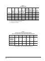
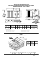
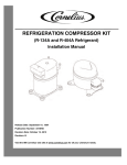
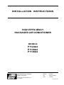
INSTALLATION INSTRUCTIONS
HIGH EFFICIENCY
PACKAGED AIR CONDITIONER
MODELS
P1124A2
P1130A2
P1136A2
Bard Manufacturing Company
Bryan, Ohio 43506
Since 1914...Moving ahead, just
as planned.
Manual :
File:
Date:
2100-323
Volume II Tab 10
01-28-98
© Copyright 1998
Contents
Getting Other Informations and Publications ........ 1
General Instructions .................................................
Important ................................................................
Shipping Damage ....................................................
Field-Installed Heater Packages (Optional) ..............
4
4
4
4
Installation ................................................................. 6
Location ................................................................ 6
Typical Installations .................................................. 6
Condensate Drain Trap ............................................ 9
Air Filters ................................................................ 9
Wiring – Main Power .............................................. 10
Wiring – 24V Low Voltage Control Circuit .............. 10
Transformer Taps ................................................... 10
Thermostats ........................................................... 10
Start Up and Operation .......................................... 11
Three Phase Scroll Compressor Start Up
Information .............................................................. 11
Sequence of Operation ........................................... 11
Start Up Notes ........................................................ 11
High Pressure Switch and Lockout Relay ............... 11
Service and Troubleshooting ................................
Service Hints ..........................................................
Pressure Service Ports ..........................................
Refrigerant Charge ................................................
Fan Blade Settings .................................................
Suction and Discharge Tube Brazing .....................
Pressure Table .......................................................
Wiring Diagrams ....................................................
12
12
12
12
12
12
13
14
Figures
Figure 1
Prefabricated Rood Curb
Specifications .......................................... 5
Figure 2 Field Fabricated Curbing ......................... 5
Figure3 Elevated Mounting Platforms .................. 7
Figure 4 Airflow and Service Access
Clearances .............................................. 7
Figure 5 Roof Top Application ............................... 8
Figure 6 Slab Mounting at Ground Level ............... 8
Figure 7 Condensate Drain Trap ........................... 9
Figure 8 Low Voltage Wiring ............................... 10
Figure 9 Fan Blade Setting Dimensions .............. 12
Figure 10 Brazing Diagram ................................... 13
Tables
Table 1
Table 2
Table 3
Table 4
Table 5
Table 6
Table 7
Table 8
Table 9
Electrical Data ......................................... 2
Optional Field Installed Heater
Packages ................................................ 2
Optional Field Installed Heater Table ....... 3
Rated CFM and Rated ESP .................... 6
Air Filter Area and Size ........................... 9
Thermostat Wire Size ........................... 10
Wall Thermostat and Subbase
Combinations ........................................ 10
Refrigerant Charge ............................... 12
Pressure Table ...................................... 13
Getting Other Information and Publications
These publications can help you install the air conditioner or
heat pump. You can usually find these at your local library
or purchase them directly from the publisher. Be sure to
consult current edition of each standard.
National Electrical Code ........................... ANSI/NFPA 70
Standard for the Installation ...................... ANSI/NFPA 90A
of Air Conditioning and
Ventilating Systems
Standard for Warm Air ............................. ANSI/NFPA 90B
Heating and Air
Conditioning Systems
Load Calculation for ................................. ACCA Manual J
Residential Winter and
Summer Air Conditioning
Duct Design for Residential ...................... ACCA Manual D
Winter and Summer Air Conditioning
and Equipment Selection
For more information, contact these
publishers:
ACCA — Air Conditioning Contractors of America
1712 New Hampshire Ave. N.W.
Washington, DC 20009
Telephone: (202) 483-9370
Fax: (202) 234-4721
ANSI — American National Standards Institute
11 West Street, 13th Floor
New York, NY 10036
Telephone: (212) 642-4900
Fax: (212) 302-1286
ASHRAE — American Society of Heating
Refrigerating, and
Air Conditioning Engineers, Incorporated
1791 Tullie Circle, N.E.
Atlanta, GA 30329-2305
Telephone: (404) 636-8400
Fax: (404) 321-5478
NFPA — National Fire Protection Association
Batterymarch Park
P.O. Box 9101
Quincy, MA 02269-9901
Telephone: (800) 344-3555
Fax: (617) 984-7057
Manual 2100-323
Page
1
TABLE 1
ELECTRICAL DATA
Q
R
Rated
Volts &
Phases
S
HZ
Maximum
External Minimum
Fuses or
Circuit
Operating Maximum
Ckt. Brk. Ampacity
Voltage
Unit
Range
Amps
Ckt. A
Ckt. A
P1124A2
230/208-1
60
197 - 253
12.9
25
17
10
10
P1130A2
230/208-1
60
197 - 253
17.6
30
21
10
10
P1136A2
230/208-1
60
197 - 253
19.4
40
25
8
10
P1136A1-B
230/208-3
60
197 - 253
14.8
25
18
10
10
P1136A1-C
460
60
414 - 506
7.1
15
12
14
14
Model
Q
R
S
R
Field
Power
Wiring
Ground
Wire Size
Ckt. A
Ckt. A
Maximum time delay fuse or HACR type circuit breaker.
75 degree C cooper wire size, basic unit only.
50 HZ equipment not UL listed.
TABLE 2
OPTIONAL FIELD INSTALLED HEATER PACKAGES
ONLY TO BE USED WITH THE AIR CONDITIONING MODEL INDICATED
Heater Package
Model No.
Volts and
Phase
EH3PB-A05
EH3PB-A08
EH3PB-A10
EH3PB-A15
240/1
EH3PB-B09
EH3PB-B15
240/3
EH3PB-CO9
EH3PB-C15
460/3
P1124A2
P1130A2
P1136A2
P1136A1-B P1136A1-C
S
S
S
S
S
S
S
S
S
S
S
A
A
A
A
A
A
A
A
A
A
A
A
A
S
S
A
A
A
A
A
A
A
A
S
S
S – Standard application – Heater volts and phase same as basic unit
A – Alternate application – Heater volts and phase different from basic unit
Manual 2100-323
Page
2
TABLE 3
OPTIONAL FIELD-INSTALLED ELECTRIC HEATER TABLE
Heater
Pkg. Model Unit Volts
No.
Phase
EH3PB-A05
EH3PB-A08
EH3PB-A10
EH3PB-A15
Htr. KW &
Capacity
@ 240V (or
480V if
applicable)
KW
BT UH
Circuit B
Htr. KW &
Capacity
@ 208 Volts
KW
BT UH
@ 240V
R
Q
S
or 480V as Heater
No. Minimum Maximum
Field Ground
applicable Internal Field
Circuit Overcurrent Power
Wire
Htr. Amps Fuses Ckts. Ampacity Protection Wiring
Size
240/208-1
240/208-1
240/208-1
240/208-1
5
8
10
15
17,100 3.75
27,300 6.0
34,100 7.5
51,200 11.25
12,800
20,500
26,000
38,400
20.8
33.3
41.7
62.5
EH3PB-B09 240/208-3
EH3PB-B15 240/208-3
9
15
30,700 6.75 23,000
51,200 11.25 38,400
EH3PB-C09 460/3
EH3PB-C15 460/3
9
15
30,700
51,200
Q
R
S
---
---
1
1
1
1
26
42
53
79
30
45
60
80
10
8
6
4
10
10
10
8
21.7
36.2
1
1
28
46
30
50
10
8
10
10
10.8
18.0
1
1
14
23
15
25
14
10
14
10
30/60
Time delay fuses or “HACR Type” circuit breakers must be used for 60 and smaller sizes. Standard fuses
or circuit breakers are suitable for sizes 70 and larger.
Based on wire suitable for 75° C. Other wiring materials must be rated for marked “Minimum Circuit
Ampacity” or greater.
Based upon Table 250-95 of N.E.C. 1993. See electrical data for basic heat pump for Circuit A wiring
specification requirements.
IMPORTANT:
While this electrical data is presented as a guide, it is important to electrically connect properly
size fuses and conductor wires in accordance with the National Electrical Code and all existing
local codes.
Manual 2100-323
Page
3
GENERAL INSTRUCTIONS
IMPORTANT
The equipment covered in this manual is to be installed by
trained, experienced service and installation technicians.
All duct work, supply and return ducts, must be properly
sized for the design air flow requirement of the equipment.
ACCA is an excellent guide to proper sizing. All duct work
or portions thereof not in the conditioned space should be
properly insulated in order to both conserve energy and
prevent condensation or moisture damage.
FIELD INSTALLED HEATER PACKAGES
(OPTIONAL)
These packaged air conditioners are manufactured without
supplementary electric heaters. Supplementary heaters
EH3PB series (to fit P1124A2, P1130A2, and P1136A2) are
available for simple, fast, field installation.
A separate field power circuit is required for the
supplementary heaters.
IMPORTANT:
SHIPPING DAMAGE
Upon receipt of equipment, the carton should be checked for
external signs of shipping damage. If damage is found, the
receiving party must contact the last carrier immediately,
preferably in writing, requesting inspection by the carrier’s
agent.
GENERAL
The refrigerant system is completely assembled and
charged. All internal wiring is complete.
The unit is designed for use with or without duct work.
Flanges are provided for attaching the supply and return
ducts.
These instructions explain the recommended method to
install the air cooled self-contained unit and the electrical
wiring connections to the unit.
These instructions and any instructions packaged with any
separate equipment required to make up the entire air
conditioning system should be carefully read before
beginning the installation. Note particularly “Starting
Procedure” and any tags and/or labels attached to the
equipment.
While these instructions are intended as a general
recommended guide, they do not supersede any national
and/or local codes in any way. Authorities having
jurisdiction should be consulted before the installation is
made.
Manual 2100-323
Page
4
Refer to Table 4 when designing duct
work for maximum available static
pressure with heater installed.
Refer to the electrical data shown on pages 2 and 3 for
proper application information on all available heater
combinations and what units they can be used with. It also
shows the applicable circuit ampacities, fuse size, and wire
size for each heater combination.
Refer to the installation instructions packed with the heater
for details on how to insert it into the basic unit.
FIGURE 1
PREFABRICATED ROOF CURB SPECIFICATIONS
HEAVY GAUGE GALVANIZED WITH WOOD NAILING STRIP, WELDED/LEAKPROOF
ONE PIECE CONSTRUCTION – READY TO INSTALL
MIS-1177
CURB AND ROOF DETAILS
Roof
Curb
A
9042-003 80-3/8
B
C*
D
E
F
J*
H*
40-1/4
37-1/4
38-3/8
35-3/8
42
14-3/4
19-1/8
*Duct Sizing Information
Return Air Dimension “C” is length
Return Air Dimension “H” is width
Roof Hood
Model
Air Conditioning Units
RHE36
P1124A2, P1130A2,
P1136A2
Supply Air Dimension “C” is length
Supply Sir Dimension “J” is width
FIGURE 2
FIELD FABRICATED CURBING
Roof Hood
Model
Unit
Model
E
RHE36
P1124A2
P1130A2
P1136A2
41
MIS-1178
Manual 2100-323
Page
5
INSTALLATION
TABLE 4
LOCATION
GENERAL
The unit must be located outside, or in a well ventilated
area. It must not be in the space being heated or cooled. A
sound absorbing material should be considered if the unit is
to be installed in such a position or location that might cause
transmission of sound or vibration to the living area or
adjacent buildings.
RATED CFM AND
EXTERNAL STATIC PRESSURE (ESP)
WET COIL (COOLING)
Rated
CFM
Rated
ESP
Recommended
Air Flow Range
P1124A2
800
.20
720 - 880 CFM
Model
P1130A2
1150
.35
1020 - 1275 CFM
SLAB MOUNTING
P1136A2
1275
.30
1150 - 1400 CFM
In areas where winter temperatures DO NOT go below
32° F for periods over twelve hours, the unit may be slab
mounted at grade level. When installing unit at grade level,
install on a concrete slab at least four inches above finished
grade level. Slab should have a slope tolerance away from
the building structure of at lease 1/4 inch per foot, while
being level from side to side. Place slab in a location where
runoff water from higher ground will not collect around unit.
See Figure 3.
TYPICAL INSTALLATIONS
A minimum of 18 inches should be provided between the
coil inlet and any building surfaces. Provide at least four
feet between coil outlet and any building wall, fences or
other vertical structures. Provide a minimum of three feet
clearance on the service access side of the unit. See
Figure 4
ROOF MOUNTING
When a unit is installed in areas where low ambient
temperatures or strong winter winds exist, it should be
placed for prevailing winter winds are not in direct line with
the outdoor coil. If this is not possible, a wind barrier
should be constructed. Place barrier 24 inches from the coil
inlet side of the unit and in the direction of prevailing winds.
Size barrier at least the same height and width as the unit.
This may be necessary on ground level installations, also.
See Figure 5.
WINTER INSTALLATION BELOW 32°F
In areas where winter conditions go below 32°F for
extended periods, the unit must be elevated above the
mounting surface to prevent snowfall or defrost ice
accumulation from interfering with the operation of the unit.
A minimum of twelve inch elevation is recommended, while
greater elevation may be required for areas of high snow
accumulation. Poured concrete, steel framework, brick,
cement block, etc., can be utilized to construct a suitable
raised mounting platform. See Figure 6.
DUCT WORK
Refer to Table 4 when designing duct work for maximum
static pressure available with the specific model and heater
package being installed.
Manual 2100-323
Page
6
1. ROOF MOUNTED – The unit is mounted on a
sturdy base on the roof of the building. Return air to the
unit is brought through a single return grille (grilles with
built-in filters are best since they enable easy access for
filter changing). Return air ducts are attached to the
lower section of the front panel. Supply air is brought
from the unit to attic duct work or to a furred down hall.
Supply air duct is attached to the top of the front panel.
CAUTION: All outdoor duct work must be thoroughly
insulated and weatherproofed. All attic duct work
must be thoroughly insulated. Two inch thick
insulation with suitable vapor barrier is
recommended for both outdoor and attic runs.
In roof top installation, as in all installations, the unit
must be level from side to side. However, the unit
should have a pitch along the length to assure complete
external drainage of precipitation.
2. CRAWL SPACE – Duct work installed in crawl
space must be well insulated and provided with a vapor
barrier. In addition, the crawl space must be thoroughly
ventilated and provided with a good vapor barrier as a
ground cover. It is most desirable to install the unit
outdoors rather than inside the crawl space, so that it
will be readily accessible for service.
3. SLAB MOUNTED AT GROUND LEVEL – This
type installation is ideal for homes with a slab floor
construction where a roof mounted unit is not desired.
The supply and return duct work can be run through a
furred closet space.
4. THROUGH THE WALL – This type installation
requires a suitable framework to be fabricated capable of
withstanding the unit weight. Normally the unit will be
insulated so as to minimize supply and return duct work.
FIGURE 3
ELEVATED MOUNTING PLATFORMS
MIS-1183
FIGURE 4
AIRFLOW and SERVICE ACCESS CLEARANCES
MIS-1185
Manual 2100-323
Page
7
FIGURE 5
ROOF TOP APPLICATION
(May also be required for ground level installations.)
MIS-1176
FIGURE 6
SLAB MOUNTING AT GROUND LEVEL
(Above 32° F Outside Temperature)
MIS-1184
Manual 2100-323
Page
8
5. OTHER INSTALLATIONS – Many other installations
are possible with the packaged air conditioner. No
matter what the installation, always consider the
following facts:
A. Insure that the discharge air is not obstructed in any
way so as to cause operation difficulties.
B. The indoor coil drain pan is equipped with a
coupling that must be piped through a condensate
drain trap to a suitable drain.
C. Always mount the unit is such a position that it may
be easily reached for servicing and maintenance.
D. Insure that the unit is clear so that proper air flow
over the outdoor coil will be maintained.
If this unit is operated in cooling below a 65° outdoor
ambient temperature, the installation of low ambient
controls (CMA-6) to unit is required.
AIR FILTERS
Air filters for the return air side of the system are not
provided as part of these models, and must be field supplied
and installed as part of the final installation.
Prior thought should be given to return air location and
placement of the air filter(s). The air filter(s) must be of
adequate size and readily accessible to the operator of the
equipment. Filters must be adequate in size and properly
maintained for proper operation. If this is not done,
excessive energy use, poor performance, and multiple
service problems will result. It is impossible to oversize air
filters. Generous sizing will result in cleaner air and coils
as well as lower operating costs and extend the time
between required changes. Table 5 shows minimum filter
areas and recommended filter sizes. Actual filter sizes can
vary with the installation due to single or multiple returns
utilizing a filter/grille arrangement or being placed
immediately ahead of the indoor coil face in the return air
duct.
CONDENSATE DRAIN TRAP
TABLE 5
It is very important to provide a trap in the condensate drain
line to allow a positive liquid seal in the line and assure
correct drainage from the coil condensate pan.
Install condensate drain trap shown in Figure 7. Use drain
connection size or larger. Do not operate unit without trap.
Unit must be level or slightly inclined toward drain. With a
trap installed on a unit located in an unconditioned area,
water in the trap may freeze. It is recommended that the trap
material be of a type that will allow for expansion of water
when it freezes.
Model
P1124A2
P1130A2
P1136A2
Minimum Filter
Areas
Recommended
Size
462 square inches
(3.21 square feet)
15 x 30-5/8 x 1
NOTE: If roof hood accessory is to be used, information
on air filters may be found under that heading in this
manual. Air filters are supplied as part of that package.
FIGURE 7
CONDENSATE DRAIN TRAP
MIS-136
Manual 2100-323
Page
9
WIRING – MAIN POWER
FIGURE 8 – LOW VOLTAGE WIRING
Refer to the unit rating plate for wire sizing information and
maximum fuse size. Each outdoor unit is marked with a
“Minimum Circuit Ampacity”. This means that the field
wiring used must be sized to carry that amount of current. If
field installed heaters are added to the basic unit, a second
separate power supply circuit will be required. The heater
rating plate located adjacent to the basic unit rating plate
will show the appropriate circuit ampacity fuse size, etc.
(Also see “Electrical Data” on pages 2 and 3.) All models
are suitable for connection with copper wire only. These
instructions must be adhered to. Refer to the National
Electrical Code for complete current carrying capacity data
on the various insulation grades of wiring material.
The electrical specifications on page 2 and 3 lists fuse and
wire sizes (75°F copper) for all models including the most
commonly used heater sizes.
The unit rating plate lists a “Maximum Time Delay Fuse” or
“HACR” type circuit breaker that is to be used with the
equipment. The correct size must be used for proper circuit
protection and also to assure that there will be no nuisance
tripping due to the momentary high starting current of the
compressor.
WIRING – 24V LOW VOLTAGE CONTROL
CIRCUIT
Five (5) wires should be run from thermostat subbase to the
24V terminal board in the unit. A five conductor, 18 gauge
copper, color-coded thermostat cable is recommended. The
connection points are shown in Figure 8.
THERMOSTATS
MIS-1180
(1) Remove jumper for 2 stage electric heat on units
with 15 or more KW
TABLE 6 – THERMOSTAT WIRE SIZE
Transformer VA
55
FLA Wire Gauge
2.3
20
18
16
14
12
Maximum
Distance
In Feet
45
60
100
160
250
TRANSFORMER TAPS
230/208V, 1 phase and 3 phase equipment employ dual
primary voltage transformers. All equipment leaves the
factory wired on 240V tap. For 208V operation, reconnect
from 240V to 208V tap. The acceptable operating voltage
range for the 240 and 208V taps are:
TAP
RANGE
240
253 – 216
208
220 – 187
NOTE: The voltage should be measured at the field power
connection point in the unit and while the unit is
operating at full load (maximum amperage
operating condition).
See specific wiring information for the different models, heater KWs, and voltages on pages 14 through 18.
TABLE 7
WALL THERMOSTAT and SUBBASE COMBINATIONS
T hermostat
Subbase
Predominant Feature
8403-019 R
(T874C1760)
8404-012
(Q674A1001)
1 stage cool, 2 stage heat
System: heat-auto-cool Fan: on-auto
8403-002 Q
(T87F3111)
8403-003
(Q539A1220)
1 stage heat, 1 stage cool
System: heat-off-cool
Fan: on-auto
-----
1 stage heat, 1 stage cool
System: heat-off-cool
Fan: on-auto
8403-009
(1F56-318)
Q No automatic changeover position – must be manually placed in heat or cool. Reversing valve
remains energized at all times system switch is in heat position (except during defrost cycle). No
pressure equalization noise when thermostat is satisfied on either heating or cooling.
R Allows thermostat to control both heating and cooling operation when set in “AUTO” position.
Reversing valve de-energizes at end of each “ON” heating cycle.
IMPORTANT NOTE: Only the thermostat and subbase combinations as shown above will work with this equipment. The
thermostat and subbase MUST be matched, and correct operation can be assured only by proper selection and
application of these parts.
Manual 2100-323
Page
10
START UP AND OPERATION
THREE PHASE SCROLL COMPRESSOR
START UP INFORMATION
SEQUENCE OF OPERATION
Scroll compressors, like several other types of compressors,
will only compress in one rotational direction. Direction of
rotation is not an issue with single phase compressors since
they will always start and run in the proper direction.
compressor contactor starting the compressor and outdoor
motor. The G (indoor motor) circuit is automatically
completed on any call for cooling operation, or can be
energized by manual fan switch on subbase for constant air
circulation.
However, three phase compressors will rotate in either
direction depending upon phasing of the power. Since there
is a 50-50 chance of connecting power in such a way as to
cause rotation in the reverse direction, verification of proper
rotation must be made. Verification of proper rotation
direction is made by observing that suction pressure drops
and discharge pressure rises when the compressor is
energized. Reverse rotation also results in an elevated
sound level over that with correct rotation, as well as,
substantially reduced current draw compared to tabulated
values.
Verification of proper rotation must be made at the time
the equipment is put into service. If improper rotation is
corrected at this time there will be no negative impact on the
durability of the compressor. However, reverse operation for
over one hour may have a negative impact on the bearing
due to oil pump out.
COOLING – Circuit R-Y makes at thermostat pulling in
HEATING – A circuit R-W1 is completed on each
heating cycle energizing electric heat if so equipped.
START UP NOTES
For improved start up performance, wash the indoor coil
with dishwasher detergent
HIGH PRESSURE SWITCH AND
LOCKOUT RELAY (All Models Except
P1136A1-B and P1136A1-C)
The air conditioners are equipped with an auto reset high
pressure switch and lockout relay. The lockout relay may be
reset by turning the thermostat to off or satisfying the
thermostat.
NOTE: If compressor is allowed to run in reverse
rotation for several minutes the compressor’s
internal protector will trip.
All three phase ZR*3 compressors are wired identically
internally. As a result, once the correct phasing is
determined for a specific system or installation, connecting
properly phased power leads to the same Fusite terminals
should maintain proper rotation direction.
The direction of rotation of the motor may be changed by
reversing any two line connections to the unit.
Manual 2100-323
Page
11
SERVICE AND TROUBLESHOOTING
SERVICE HINTS
FIGURE 9
FAN BLADE SETTING DIMENSIONS
1. Caution homeowner to maintain clean air filters at all
times. Also, not to needlessly close off supply and
return air registers. This reduces air flow through the
system which shortens equipment service life as well as
increasing operating costs.
2. Check all power fuses or circuit breakers to be sure that
they are the correct rating.
3. Periodic cleaning of the outdoor coil to permit full and
unrestricted airflow circulation is essential.
Model
Dimension A
P1124A2
P1130A2
P1136A2
1.00"
.75"
1.00"
PRESSURE SERVICE PORTS
High and low pressure service ports are installed on all units
so that the system operating pressures can be observed.
Pressure tables can be found in Table 9 in this manual
covering all models on cooling cycle. It is imperative to
match the correct pressure table to the unit by model
number.
SUCTION AND DISCHARGE TUBE
BRAZING
REFRIGERANT CHARGE
The correct system R-22 charge is shown on the unit rating
plate. Optimum unit performance will occur with a
refrigerant charge resulting in a suction line temperature
(6” from compressor) as shown in Table 8.
TABLE 8
Model
Rated
Airflow
95 Degree F
OD
Temperature
P1124A2
P1130A2
P1136A2
800
1150
1275
56 - 58
56 - 58
57 - 59
82 Degree F
OD
Temperature
63 - 65
63 - 65
58 - 60
Compliant Scroll compressors have copper plated steel
suction and discharge tubes. These tubes are far more
rugged and less prone to leaks than copper tubes used on
other compressors. Due to different thermal properties of
steel and copper, brazing procedures may have to be
changed from those commonly used.
•
To disconnect: heat joint Areas 2 and 3 slowly and
uniformly until braze material softens and the tube can
be pulled out of suction fitting. (See Figure 10.)
•
To connect:
–
Recommended brazing materials: silfos with
minimum 5% silver or silver braze material with
flux.
–
Reinsert tube into fitting.
–
Heat tube uniformly in Area 1 moving slowly to
Area 2. When joint reaches brazing temperature,
apply brazing material. (See Figure 10.)
FAN BLADE SETTINGS
–
Shown in Figure 9 are the correct fan blade setting
dimensions for proper air delivery across the outdoor coil.
Heat joint uniformly around the circumference to
flow braze material completely around the joint.
–
Slowly move torch into Area 3 to draw braze
material into joint. (See Figure 10.)
–
Do not overheat joint.
The above suction line temperatures are based upon 80°F dry
bulb/67°F wet bulb (50% RH) temperature and rated airflow
across the evaporator during cooling cycle.
Any service work requiring removal or adjustment in the fan
and/or motor area will require that the dimensions below be
checked and blade adjusted in or out on the motor shaft
accordingly.
Manual 2100-323
Page
12
FIGURE 10
BRAZING DIAGRAM
MIS-1179
TABLE 9
PRESSURE TABLE
COOLING
Air Temperature Entering Outdoor Coil Degrees F
Model
P1124A2
P1130A2
P1136A2
Return Air
Pressure
Temperature
75
80
85
90
95
100
105
110
115
75 deg. DB
62 deg. WB
Low Side
High Side
70
219
74
220
77
224
79
234
80
248
82
258
83
276
84
293
85
316
80 deg. DB
67 deg. WB
Low Side
High Side
75
224
79
225
82
230
84
240
86
254
88
265
89
283
90
300
91
324
85 deg. DB
72 deg. WB
Low Side
High Side
81
232
85
233
88
238
90
248
92
263
95
274
96
293
97
311
98
335
75 deg. DB
62 deg. WB
Low Side
High Side
73
200
75
219
76
234
77
254
79
271
80
288
81
307
82
327
83
342
80 deg. DB
67 deg. WB
Low Side
High Side
75
205
80
225
81
240
82
260
84
278
85
295
86
315
87
335
88
351
85 deg. DB
72 deg. WB
Low Side
High Side
84
212
86
233
87
248
88
269
90
287
91
305
92
326
94
347
95
363
75 deg. DB
62 deg. WB
Low Side
High Side
67
195
71
215
73
229
75
249
77
263
78
282
79
302
80
317
81
336
80 deg. DB
67 deg. WB
Low Side
High Side
72
200
76
220
78
235
80
255
82
270
84
290
85
310
86
325
87
345
85 deg. DB
72 deg. WB
Low Side
High Side
77
207
82
228
84
243
86
264
88
279
90
300
91
321
92
336
94
357
Manual 2100-323
Page
13