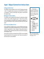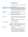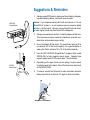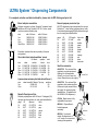
1
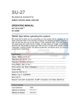
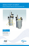
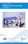
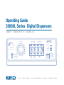
Operating Guide
2000XL Series Digital Dispensers
2000XL
•
2000XL-PR5-15
•
2000XL-CA
®
Pressure
Cell Select
Time Set
Fast
Slow
A NORDSON COMPANY
STEADY
RUN
SETUP
Vacuum
CYCLE
Vacuum
Pressure
Run
Setup
Steady
Teach
Fast
Slow
Time Set
Pressure
Time
STOP
®
In the US: 800-556-3484
A NORDSON COMPANY
In the UK: 0800 585733
In Mexico: 001-800-556-3484
Introduction
The 2000XL Series dispensers provide years of trouble-free,
productive service. This Operating Guide will help you maximize the
usefulness of your new dispenser.
Please spend a few minutes to become familiar with the controls and
features of your new dispenser. Follow our recommended testing
procedures. Review the helpful information we have included based
on over 30 years of industrial dispensing experience.
Most questions you will have are answered in this guide. However,
if you need assistance, please do not hesitate to contact EFD or your
authorized EFD distributor.
☎
In the US, call 800-556-3484.
In Mexico, call 001-800-556-3484.
In the UK, ring free 0800 585733.
The EFD Pledge
We pledge that you will be completely satisfied with our products.
We endeavor to ensure that every EFD product is produced to our
no-compromise quality standards.
If you feel that you are not receiving all the support you require, or if
you have any questions or comments, I invite you to write or call me
personally.
Our goal is to build not only the finest equipment and components,
but also to build long-term customer relationships founded on
superb quality, service, value and trust.
Randall Richardson, President
Contents
Getting Started ............................................................................. 4
Specifications
First Steps .................................................................................... 5
Unpacking the dispenser & Activating your Ten Year No-fault Warranty
Features and Controls .............................................................. 6-7
Indicator Lamps ....................... 7
Setup ..................................................................................... 8-10
Setup procedures .................. 8-9
Diagram ................................. 10
Final checklist ........................ 10
Testing the 2000XL .............................................................. 11-12
Programming deposit size ..... 12
Operational Features ................................................................. 13
ULTRA Dispensing System .................................................. 14-15
How to Use the Vacuum Control .......................................... 16-17
Loading the Barrel Reservoirs .............................................. 18-19
Memory Function ................................................................. 20-21
Input and Output Connection Instructions ................................. 22
Schematic and Replacement Parts List ..................................... 23
Troubleshooting ......................................................................... 24
Suggestions and Reminders ...................................................... 25
Reordering Components ............................................................ 26
Ten Year No-fault Warranty ....................................................... 27
This manual is for the express and sole use of EFD
dispenser purchasers and users, and no portion of
this manual may be reproduced in any form.
EFD, ULTRA System, LV Barrier and SmoothFlow
are trademarks of EFD Inc. ©2002 EFD Inc.
Meets applicable CSA and CE requirements.
Getting Started
The 2000XL Series automatic fluid dispensers are designed to
provide complete process control using advanced microprocessor
circuitry. All microprocessor functions are accessed by push button.
Microprocessor features include:
• Push-button time setting input or one-touch time programming.
• Floating decimal, providing dispense time ranges of 0.001 to 9.999
and 00.01 to 99.99 seconds.
• Backlit LCD displays time settings, dispensing pressure and
vacuum pressure.
• Dispensing pressure display is programmable for either psi or bar
scale.
• Memory with storage for up to eight separate time settings.
Intelligent technology makes the 2000XL Series easy to set up and
use. With one-touch setup, just press the pedal to determine the
proper amount. The microprocessor remembers the time and
repeats this amount with each cycle until you are ready to change it.
From microdeposits to volumetric filling, the 2000XL provides the
ultimate in control and versatility for time/pressure-based fluid
dispensing.
5.570"
14.1 cm
Pressure
Cell Select
Time Set
Fast
Slow
2000XL
A NORDSON COMPANY
STEADY
Specifications
Cabinet size:
7.470 x 5.570 x 2.700"
(19.0 x 14.1 x 6.9 cm)
Weight
3 lb 3 oz
1.44 kg
Input voltage:
Selectable 100/120/220 VAC
50/60 Hz 10/9 VA
End-of-cycle feedback circuits:
5 to 24 VDC N.C. solid-state switch
250mA maximum (details page 23)
Initiate circuit: Foot pedal or
5 to 24 VDC signal
Air consumption: Approximately 1.5
SCFM at 400 cycles per minute
Cycle rate: Exceeds 600 per minute
Time range: Programmable 0.001 to
9.999, or 00.01 to 99.99 seconds
2000XL
air input:
80 to 100 psi (5.5 bar to 6.9 bar)
air output:
0 to 100 psi (0 to 6.9 bar)
2000XL-PR5
air input:
10 to 50 psi (0.7 bar to 3.4 bar)
air output:
0 to 5 psi (0 to .34 bar)
2000XL-CA
air input:
80 to 100 psi (5.5 bar to 6.9 bar)
air output:
0 to 15 psi (0 to 1.0 bar)
RUN
2.700"
6.9 cm
SETUP
3.380"
8.6 cm
CYCLE
Vacuum
Vacuum
Pressure
Run
Setup
Steady
Teach
7.470"
19.0 cm
Fast
Slow
Time Set
Pressure
Time
STOP
Note: Specifications and technical
details are subject to engineering
changes without prior notification.
First Steps
First: Unpack and use the checklist enclosed with the Dispenser Kit
to identify all items. If there is any discrepancy, please call us
immediately.
Second: Power and compressed plant air should be available where
the dispenser is to be set up. Input air should be set between 80 and
100 psi (5.5 and 6.9 bar). For model 2000XL-PR5, input air should
be set between 10 and 50 psi (0.7 and 3.4 bar). If you are not using
an EFD five-micron filter regulator #2000F755, be certain your
plant air is properly filtered and dry and a regulated, constant
air pressure is supplied to the dispenser.
Note: Model 2000XL-CA is supplied with an EFD five-micron filter
regulator with coalescing filter (#2000F756).
Bottled nitrogen can be used.
Warning: If high pressure bottled air or nitrogen is used, a high
pressure regulator must be installed on the bottle and set at 100 psi
maximum. The 2000F755 filter regulator is not required.
Check the voltage label to be certain it is set to the available power.
Third: Now is a good time to ACTIVATE your extended Ten Year
No-fault Warranty. Please fill in and return the postage paid
Warranty card. Or if you prefer, call the appropriate toll-free number
listed below, provide the serial number of your dispenser and
respond to a few short questions.
☎
In the US, call 800-556-3484.
In Mexico, call 001-800-556-3484.
In the UK, ring free 0800 585733.
Features and Controls
Barrel vacuum
control
®
Pressure
Cell Select
Time Set
Fast
Slow
2000XL
A NORDSON COMPANY
STEADY
Function
Indicator
Lamps
RUN
C
Vacuum
Vacuum
Pressure
Vacuum
toggle switch
Run
Setup
E
Steady
Teach
L
1
SETUP
Fast
Slow
Time Set
Pressure
Time
CYCLE
STOP
Air pressure
regulator
Digital Time, Air Pressure and
Vacuum Pressure LCD Display
in a TEACH mode (refer to page 12 for TEACH
procedures).
• Programmable floating decimal provides time range
readout from 0.001 to 99.99 seconds.
• Air pressure readout can be programmed in either
psi or bar.
• Vacuum pressure readout is displayed by holding
the vacuum toggle switch in the "up" position.
In RUN mode, pressing STEADY/TEACH will override the
timer and dispense for as long as the foot pedal is
pressed. The dispenser display will read "----" in the
STEADY mode.
Time Set ▼ (down)
▲ (up)
Can store up to eight Time settings. (See page 20.)
In SETUP mode, use the TIME SET buttons to change
time settings. Left buttons scroll digits quickly; right
buttons scroll digits slowly.
Run/Setup
Pressure/Time
1. The RUN mode allows access to all eight cells. Cell
numbers are displayed as CEL1, CEL2....CEL8. Changing the cell number will change the time setting corresponding to that cell.
The SETUP mode provides access to selected cell
TEACH and TIME SET functions. Only in the SETUP mode
can cell time values be viewed, cleared, or changed.
2. In the RUN mode, the functions are inoperative.
Press to change display values from TIME to PRESSURE
or PRESSURE back to TIME.
Memory
In SETUP mode, pressure readings may be changed
from PSI to BAR and BAR to PSI by pressing and
holding the PRESSURE/TIME button for four seconds.
STOP
This button stops the dispenser immediately.
Barrel Vacuum Control
Steady/Teach
In SETUP mode, pressing STEADY/TEACH will clear
the currently displayed cell setting, reset the cell
display to blinking "0000", and place the dispenser
Refer to page 16 for operation.
Air Pressure Regulator
Refer to page 11 for operating instructions.
Voltage selector
and fuse cartridge
Air output
quick-connect
Fuse T 125mA 250V
100/120/220VAC
50/60Hz 10/9VA
Power
switch
Foot pedal
receptacle
Exhaust
Indicator Lamps
Exhaust
Air
Output
Foot
Pedal
®
Air
Input
t
Slow
2000XL
A NORDSON COMPANY
STEADY
1. Initiate +
5-24 VDC
2. Initiate 3. Output + 5-24 VDC
4. Output - 250mA
5. Contact Closure
6. Chassis Ground
7. Contact Closure
8. Not Used
9. Not Used
RUN
SETUP
CYCLE
Power input
receptacle
I/O 9 pin interface
connector
Air input
Power Input Receptacle with Voltage Selector and Fuse Cartridge
Three input voltages can be used: 100 VAC, 120 VAC and 220 VAC. To
change input voltage, remove fuse cartridge and position the selected
voltage marked on the cartridge so that it shows through the window.
(Details on page 8.)
Input/Output 9 Pin Interface Connector
The input/output features are used when the dispenser is interfaced with
external control circuits.
• An End-of-Cycle signal, in the form of a solid-state switch, closes upon
completion of the dispense cycle. Maximum load is 250mA from 5 to
24 VDC.
• The 2000XL can be initiated using a 5 to 24 VDC signal.
• Contact Closure.
(For more details, refer to page 22.)
Slow
t
Pressure
Time
STOP
In the upper right corner of the
front panel are four indicator
lamps. These lamps indicate
the mode of operation.
STEADY - Indicates that the
timing feature has been
overridden and that the output
is controlled by the length of
time the foot pedal is pressed.
RUN - Indicates that the
dispenser is in the RUN mode
ready to be initiated through a
dispense cycle. In this mode,
time settings cannot be
changed.
SETUP - Indicates that the
dispenser is in the SETUP
mode. In this mode, time
settings can be changed.
CYCLE - This lamp is on during
the dispense cycle.
Setup
Power switch should be off.
❶ Mounting
Check the input power cord receptacle. To change
voltage, remove the voltage selector from the cartridge, rotate it and position the correct voltage to
show through the cartridge window. Replace the
cartridge into the power cord receptacle and insure
that both sides snap securely into position.
❷
Spare fuse
22
0
120
❷ Input power
❶
10
0
Included is a universal mounting bracket. Mounting
hardware is installed into the four 10-32 mounting
holes on the sides of the cabinet. The bracket can be
mounted either over or under the cabinet and will
allow the dispenser to pivot up or down 30° from a
horizontal position. The bracket may be permanently
mounted, or attach the rubber feet included and use
the bracket as a bench-top tilt stand. Four rubber feet
on the console are provided if the bracket is not used.
Voltage value
Cartridge window
Note: Check voltage indicated
Install the power cord.
❸ Initiate connection
The 2000XL is normally operated using the foot pedal
supplied. Plug the foot pedal into the connector
located on the rear panel. An alternate method is to
apply a 5 to 24 VDC pulse to terminals 1 and 2.
❹ Air input connection
A 6 ft. air input hose kit is supplied. Connect the input
hose to filtered, dry plant air. For models 2000XL and
2000XL-CA, set plant air supply within 80 to 100 psi
(5.5 to 6.9 bar). For model 2000XL-PR5, input air
should be set within 10 to 50 psi (0.7 to 3.4 bar).
Attach the air input hose coupling to the dispenser.
Pull back metal ring to attach to dispenser.
❻
Fuse T 125mA 250V
100/120/220VAC
50/60Hz 10/9VA
❺ ❸
Exhaust
Foot
Pedal
Air
Output
Air
Input
1. Initiate +
5-24 VDC
2. Initiate 3. Output + 5-24 VDC
4. Output - 250mA
5. Contact Closure
6. Chassis Ground
7. Contact Closure
8. Not Used
9. Not Used
❹
Note: If filtered, dry air is not available, order an
EFD five-micron filter regulator #2000F755.
(2000XL-CA units are supplied with a five-micron
coalescing filter regulator.)
❾
Pressure
Cell Select
Time Set
Fast
Slow
®
2000XL
A NORDSON COMPANY
STEADY
RUN
Vacuum
Vacuum
Pressure
❿
C
E
Run
Setup
Steady
Teach
1
SETUP
Fast
Slow
Time Set
Pressure
Time
L
CYCLE
❽ Setting the pressure readout
The dispenser is shipped with pressure display
programmed in psi.
STOP
❽❼
Note: On models with 5 psi and 15 psi regulators,
the pressure is adjustable in 0.1 psi increments.
❺ Power on/off
If bar is desired, change as follows:
Press the Power Switch located on the rear panel
to the "ON" position. The dispenser will power up
in the RUN, STEADY, or PRESSURE mode and indicate which cell was selected last. (Dispenser is
shipped with CEL1 selected in RUN mode).
Press RUN/SETUP and place the dispenser into the
SETUP mode. Press and hold the PRESSURE/TIME
button for 4.0 seconds. The display will change
from psi to bar. To change back to psi, press and
hold PRESSURE/TIME for 4.0 seconds.
❻ Air output
❾ Vacuum control
Vacuum is turned off (clockwise) during testing
procedures. (Refer to page 16 for operation.)
Push in and twist lock the 10cc adapter assembly
(part # 1000Y5150). The number 5150 is molded
on the side of the yellow head.
❼ Setting the decimal
The dispenser is shipped with the decimal set at
hundredths of a second (00.00). The decimal can
be moved to show thousandths of a second (0.000)
as follows:
Press RUN/SETUP to place the dispenser in SETUP
mode.
To move the decimal, press and hold the STOP
button. After approximately 4.0 seconds, the
decimal will move to the thousandths position. To
return to the hundredths position, press and hold
the STOP button again.
Note: Changing the decimal place changes the
current time setting by a factor of 10. For example,
5.35 seconds becomes 53.50; 15.00 seconds
becomes 1.50.
❿ Vacuum toggle switch
To read vacuum pressure, hold toggle switch in
the "up" position. Readout will appear on the
digital display pad, then return to air pressure
readout when toggle is released.
Continue to page 11 for test procedures.
❹
Note: Plant air, 125 psi maximum to regulator. Output from
regulator should be a minimum of 80 psi, maximum 100 psi.
For model 2000XL-PR5, output from regulator should be
set at 30 psi.
❺
Air input hose
Barrel
adapter
assembly
Power cord
Male
quick-connect,
insert and twist
to lock.
Check voltage label
on dispenser.
Foot pedal
assembly
®
Pressure
Cell Select
Time Set
Fast
Slow
2000XL
A NORDSON COMPANY
STEADY
RUN
SETUP
CYCLE
Vacuum
❸
Vacuum
Pressure
Run
Setup
Steady
Teach
❶ ❻
Fast
Slow
Time Set
Pressure
Time
❷
STOP
Note: For hookup purposes,
the connections for the 2000XL,
2000XL-PR5 and 2000XL-CA
models are identical.
Setup for Testing
Deposit size is controlled by TIME, PRESSURE and
TIP SIZE.
Attach the barrel containing the test material to the
adapter assembly ❹ as shown.
Please follow these instructions in order to test
each function. Use the convenient Dot Test
sheet included in your Test Kit.
Remove the orange tip cap from the end of the
dispensing barrel and attach the green 18 gage
tapered tip ❺ found in the Dot Test Kit. Place the
barrel in the barrel stand.
Setup for Testing
Press RUN/SETUP ❶ to set the dispenser into the
RUN mode (RUN indicator light on).
Press STEADY/ TEACH ❻ to place the 2000XL into
STEADY mode. (STEADY indicator light on.)
❷ and set display to
Rest the dispensing tip on the Dot Test sheet.
Press and hold the foot pedal until the tip fills with
test material.
Pull out air pressure regulator knob ❸ until it
"clicks" into the unlocked position. Turn clockwise to adjust the pressure to 20 psi (1.4 bar).
Go into TIME mode by pressing STEADY/ TEACH ❻
again (STEADY indicator light goes out) and time is
displayed.
Note: Dispensers with 5 psi or 15 psi gauges
should be tested with the clear test fluid, using a
lavender 30 gage tip and air pressure set at 5 psi.
Refer to "How to Use the Vacuum Control" on
page 16.
Press RUN/SETUP ❶ to place the 2000XL into the
SETUP mode (SETUP indicator light on). Press
STEADY/ TEACH ❻ to zero the display.
Press PRESSURE/TIME
pressure.
Always set the pressure desired by turning the air
regulator knob clockwise. To reduce the pressure, turn the knob counterclockwise until the air
gauge reads a lower pressure than desired.
Then increase and stop at desired pressure.
Push knob in to lock.
Dispensers with air pressure gauges higher than
15 psi are tested using the nontoxic blue fluid
supplied in the Dot Test kit. This fluid is representative of thick, non-leveling fluids such as
sealants, pastes and greases and is used to
demonstrate the different control settings.
Continue to page 12 for tests which will demonstrate the ease at which deposit sizes can be
established using the foot pedal or TIME SET
feature.
Testing (continued)
Program (TEACH) the Deposit Time with the Foot Pedal
When a specific time value is not known, as when first
dispensing an amount, the time may be programmed using the
foot pedal.
Press RUN/SETUP to set the dispenser into RUN mode (RUN
indicator light on). Select the memory cell you wish to program,
e.g. CEL1, CEL2....CEL8.
Return the dispenser to SETUP mode and clear cell memory by
pressing STEADY/TEACH. The dispenser displays a blinking
"0000" to indicate that it is in TEACH mode and ready for
programming.
Holding the barrel as shown, rest the tip on the Dot Test sheet.
Press the foot pedal for about one second. Notice that the
display now shows the length of time the foot pedal was
pressed.
Correct angle for consistent deposits.
Keeping the tip in the same place, press the pedal again for
about two seconds and add to the first deposit. Now the display
shows the total time for both deposits.
You can build up to the desired amount by simply pressing the
foot pedal repetitively until the deposit is the proper size. If the
deposit becomes too large, press STEADY/TEACH and start
again. Press RUN/SETUP to save the setting and return to the
RUN mode.
Program the Deposit Time with a Specified Time Setting
Set the dispense time when the desired time SET buttons
below the display to scroll up and TIME SET buttons above the
display to scroll down. The button on the right scrolls slowly
for single digit setting; the one to the left scrolls fast.
Press STEADY/TEACH, then set the time to 1.15 seconds using
the TIME SET buttons. Press RUN/SETUP to return to the RUN
mode. Press the pedal and make a 1.15 second deposit.
Remember - always bring the tip in
contact with the work surface at
the illustrated angle. After the tip
is in position, press the foot pedal.
Release pedal and remove tip by
lifting straight up.
Note: The pedal needs only to be pressed momentarily. The complete time cycle will run once
the dispenser is initiated.
Don’t Forget!
✓ Changes to the time settings can be
made only when the mode of operation
is SETUP.
Press RUN/SETUP and toggle back to the SETUP
mode. Press the TIME SET buttons and change
the time to 2.30 seconds. Go back to RUN, press
the foot pedal, and the dispenser will make a
deposit approximately twice the size of the first one.
✓ RUN mode locks out TIME SET and TEACH
control buttons. Use this to protect the
setup from inadvertent changes.
Pressure—changes deposit size.
✓ Pressing STEADY/TEACH in SETUP mode
will clear all time settings within cell.
The dispenser should be in the RUN mode, the
TIME setting should be 2.30 seconds and the
dispensing pressure should be 20 psi (1.4 bar).
✓ STOP immediately terminates the current
dispense cycle.
Increasing the pressure will result in larger deposits, decreasing the pressure will result in smaller
deposits. Try this now and observe the results.
✓ Use only dry, clean, filtered air.
Tip Size—changes deposit size.
Tip size also affects deposit size. Without changing the TIME or PRESSURE setting, try different tips
and observe the results.
☎
If you have any questions at this point, please call us now.
In the US, call 800-556-3484
(Between 8:30 am and 6:00 pm eastern time.)
In Mexico, call 001-800-556-3484.
In the UK, ring free 0800 585733.
Advanced Dispensing System
TM
If you dispense thick fluids, several problems may
occur. First, the repetitive air cycles can bore
tunnels through non-leveling fluids, causing
spitting and inconsistent deposits. Second, thick
fluids contain trapped air that leads to drooling
and oozing.
For Thick Fluids
Air Pressure
ON
Air Pressure
OFF
These problems are eliminated by using the
SmoothFlow™ piston. That's because the white
pistons prevent tunneling by providing a barrier to
the pulsed-air cycles, and prevent oozing by
responding to the pressure of trapped air with a
slight suck-back movement after the dispense
cycle.
The white piston is used for most fluids.
However, if you are applying RTV silicone and
find that the piston bounces and causes stringing,
switch to the orange, flat wall piston.
The SmoothFlow™ pistons make barrel filling
easier, too. As you load the fluid in, air is trapped
in the bottom and throughout the fluid. Simply
insert a SmoothFlow™ piston and gently press
down on the fluid as far as possible. This action
forces out most of the air and results in consistent
deposits.
No drip
or ooze.
If you use low to medium viscosity fluids, the white
SmoothFlow™ piston has several advantages.
First, vacuum adjustment is much less sensitive.
Second, the piston prevents fumes from the fluid
being exhausted into the work environment. Third,
the piston prevents fluid backflow into the dispenser if the barrel is inadvertently turned upside
down. Fourth, using the piston makes it easy and
safe to change tips without dripping.
Note: If you use watery-thin fluids such as solvents,
cyanoacrylates and anaerobics, specify the ULTRA
System™ with the blue LV Barrier™. Available in
3cc and 10cc sizes.
For Cyanoacrylates
or Watery-thin Fluids
For Thinner Fluids
SmoothFlow™ piston
prevents fluid backflow.
Fumes cannot escape.
No air gap when using the
SmoothFlow™ piston.
Blue LV Barrier™ for improved
control of very low viscosity fluids.
Maximum
1/2 fill
Note: The LV Barrier ™ works best
with an air gap between the barrier
and fluid.
Note: If you choose not to use the piston,
please refer to page 17 for instructions.
How to use the Vacuum Control
The vacuum control allows low viscosity fluids, even water, to be
consistently dispensed without dripping between cycles. The vacuum
exerts a negative pressure on the liquid in the barrel and prevents
dripping.
For these tests, you will use the test barrel with the clear fluid.
1. While holding the barrel upright in one hand, remove the orange
end cap and insert the blue LV Barrier™. Allow an air gap as
shown.
Remove
orange
end cap.
Insert
blue LV
Barrier™
2. Attach the barrel to the 10cc adapter. Snap the safety clip tightly
closed to prevent any dripping or bubbling. Remove the tip cap
and attach the 30 gage (lavender) tip.
3. Set air pressure at 5 psi.
4. Press RUN/SETUP to go into SETUP mode and set TIME for 00.05
seconds. Press RUN/SETUP to return to RUN mode.
5. Press STEADY/TEACH (STEADY indicator light on).
6. With the barrel pointing downward over a container, unsnap the
safety clip and press the foot pedal to fill the tip.
7. If a drop begins to form at the end of the tip, slowly turn the
vacuum control knob counterclockwise to stop the drop from
growing. Wipe the tip and adjust vacuum as necessary.
8. To read vacuum pressure, press PRESSURE/TIME so that system
air pressure is displayed. Hold toggle switch in the "up" position
to view vacuum pressure. Release toggle to return display to
system air pressure readout.
9. Press STEADY/TEACH (STEADY indicator light off).
10. Take the barrel and place the tip on the test sheet. Press the foot
pedal and release. Check the dot size. Increase or decrease by
adjusting pressure or time.
Remove
tip cap.
If you choose not
Three things to remember
If you do not use the piston when
dispensing thin fluids:
+to use the piston, please follow these instructions carefully:
1. While holding the barrel upright in one hand, twist on an orange
tip cap. Using the small funnel, fill about 2/3 full with your fluid.
2. Open the safety clip and attach the barrel to the 10cc adapter.
3. Close the safety clip as tight as possible.
Do not tip the barrel upside down
or lay flat. This will cause the
liquid to run into the dispenser.
Open
Closed
When changing tips
or attaching a tip cap,
snap the safety clip
completely closed to
prevent any dripping
or bubbling.
Use an EFD filter trap
(#1000FLT-Y). This
filter trap will impede
the flow should the
low viscosity liquid be
sucked back towards
the dispenser.
4. Slightly increase vacuum by turning vacuum control knob
counterclockwise.
5. Then, without tipping the barrel upside down, remove the tip cap
and attach the 30 gage (lavender) tip.
6. Open the safety clip. Your material may begin to bubble. Reduce
vacuum by turning vacuum control knob clockwise.
7. If a drop begins to form at the end of the tip, slowly turn the vacuum
control knob counterclockwise to stop the drop from growing.
Wipe the tip and adjust vacuum as necessary.
Now the fluid is in proper balance. It does not bubble or drip.
Repeat tests as before, keeping the air pressure low and adjusting
the time for different deposit sizes.
☎
In the US, call 800-556-3484.
In Mexico, call 001-800-556-3484.
In the UK, ring free 0800 585733.
Loading the Barrel Reservoirs
Caution: Do not completely fill barrels. The optimum fill is a maximum
2/3 of the barrel capacity and 1/2 of the barrel capacity when using
the LV Barrier™.
If the fluid you are dispensing is pourable, take the barrel, twist on a
tip cap and pour your fluid in. If appropriate, insert the SmoothFlow™
piston (see page 14). Carefully press the piston down until it contacts
the fluid. The barrel is now ready for use.
If you are dispensing watery solvents, cyanoacrylates or anaerobics,
use the LV Barrier™. Place barrier in the top of the barrel reservoir.
Allow air between barrier and fluid. Do not contact the barrier to the
fluid.
If your fluid is thick or non-leveling, you can spoon it into the barrel with
a spatula. Or, if the fluid comes packed in a 1/10 gallon cartridge, try
loading the barrel with a caulking gun. Then, press in the SmoothFlow™
piston to move the fluid to the bottom of the barrel and to remove
trapped air.
2/3
maximum
fill
Fill procedure for
pourable fluids
Fill procedure for thick fluids
(shown: caulking gun)
LV Barrier™
Air gap
1/2 maximum fill
2/3
maximum
fill
Fill procedure for cyanoacrylates
or watery-thin fluids
White
SmoothFlow™
piston
EFD offers productive alternatives to traditional barrel loading methods. Here are a few suggestions that can help keep your work area
clean, save time and reduce the chance of entrapped air in the fluid.
1. You could use the EFD #920BL barrel loader. Pack the fluid into
the 12 ounce cartridge as shown. Then place the prefilled
cartridge into the barrel loader. Using air pressure, the barrel
loader fills the barrel (with piston) from the bottom up.
If the fluid comes packed in a 1/10 gallon (300 ml.) caulking type
cartridge, use the EFD #940BL barrel loader.
2. If you receive frozen epoxies or other fluids in medical type
syringes with a manual plunger, request our luer-to-luer fitting
#2160 to transfer the material.
Filling the cartridge
for the barrel loader.
Please call an EFD Fluid Application Specialist
for additional assistance.
2/3
Maximum
Fill
EFD #920BL Barrel Loader
(Specify #940BL for prefilled 1/10 gallon caulking tubes)
Barrel Rack
#905BR for 3cc and 5cc barrels
#910BR for 10cc, 30cc and 55cc barrels
#2160 Luer-to-luer fitting
Memory
The memory feature enables storage of up to eight different time
settings that can be recalled and used at the push of a button. Time
settings are saved even with power removed and will remain in
storage unless changed or erased intentionally. Memory cells are
identified as CEL1 through CEL8.
Viewing MEMORY cells
C
E
L
3
Before saving a time setting in memory, view the memory cells to see
which cells are empty or, if all cells are used, which time can be
replaced.
Figure 1
To prevent accidental data loss, review the contents of each cell
before selecting and storing a new time setting into memory.
3.
Figure 2
2
5
1. Press RUN/SETUP to place the dispenser in RUN mode (RUN
indicator light on). The current cell number will be displayed. e.g.,
CEL3. (Figure 1)
2. Press CELL SELECT (up) (down) to select the cell you wish to use.
3. Press RUN/SETUP again to return the dispenser to SETUP mode
(SETUP indicator light on). The time setting stored in the selected
cell will be displayed. (Figure 2)
NOTE: To avoid unintentional loss of stored settings, do not press
STEADY/TEACH in SETUP mode (doing so will clear the previously
stored cell setting). Always return the dispenser to RUN mode after
viewing or changing contents.
Saving a time in a MEMORY cell
1. Determine the cell in which a new time value is to be stored, e.g.,
CEL1, CEL2... (Refer to "Viewing MEMORY cells" on page 20).
2. Press RUN/SETUP to place the dispenser in SETUP mode (SETUP
indicator light on).
Note: Once cell value s are cleared, they canot be recalled.
3. Press STEADY/TEACH to clear cell contents.
4. Enter the desired time setting by using the TIME SET button or the
TEACH function and foot pedal (refer to page 12).
5. Press RUN/SETUP to place the dispenser in RUN mode (RUN
indicator light on) and save the setting in cell memory.
The dispenser is now ready to use the preset value you just stored.
To recall and use a time in MEMORY
In the RUN mode, press CELL SELECT (up) (down) to step through the
cells until you locate the desired cell. The dispenser is now ready to
use the time stored in the selected cell.
Input / Output Connection Instructions
Voltage Initiate Circuit
The 2000XL may be initiated with a 5 to 24 VDC signal across pins
1 and 2. The signal can be momentary (no less than 0.001 seconds)
or maintained. A new cycle will begin once power is removed and
then applied again.
Mechanical Contact Initiate
The 2000XL can be initiated via the closure of mechanical contacts
such as a relay or switch using pins 5 and 7. Closure of the contacts
can be momentary (no less than 0.001 seconds) or maintained. A
new cycle will begin once the contacts are opened and then closed
again.
End-of-Cycle Feedback Circuit
Upon completion of a dispense cycle, an open collector circuit closes
and remains closed until the next dispense cycle. This circuit can be
utilized to signal back to a host computer, start another device in
sequence or other operations that need to be tied into the completion
of the dispense cycle.
Upon closure, power from an external 5 to 24 VDC source is allowed
to pass through the circuit to operate a load. Power consumption of
the load must not exceed 250mA.
I/O Connection
The 9 pin D connector and
internal circuitry provide
external initiate and endof-cycle feedback signal.
The pin connections are
shown below.
5 4 3 2 1
9 8 7 6
Pin
1.
2.
3.
4.
5.
6.
7.
8.
9.
Function
Initiate +
5-24 VDC
Initiate
Output + 5-24 VDC
250mA Max
Output
Contact Closure
Chassis Ground
Contact Closure
Not Used
Not Used
]
]
Note: A 9-pin male connector
assembly is available from EFD.
Order part no. 7154.
Schematic & Parts
1. 7104B
Display board assembly
2. 7109
3. 7105B
Power switch
Power supply
board assembly, 100 psi
7105C
4. 7123
5. 2-7125-VR
2-2003LF-PR
6. 2004B
7. 7131
7132
8. 2015A
9. 7111
10. 7106D
11. 2084-1
12. 2085
13. 2087
14. 2094
15.
16.
17.
18.
19.
20.
21.
22.
23.
24.
25.
2024-160
2009-A24
7143-01
2-2002A-VR
2-2002-VR
2-2002LP-PR
2081A
1000INP-AKIT
2170
2-2176-P
2-2017-2000
2-2010
2079
* Not Shown
10
Power supply
board assembly
5 and 15 psi
Transformer
Solenoid assembly*
Solenoid assembly*
(2000XL-PR5)
Air quick-connect
Pressure sensor, 100 psi
Pressure sensor, 15 psi
Foot pedal assembly*
Fuse
Fuse holder
Restrictor fitting
1/8 NPT male - 1/4 barb
elbow low profile
1/8 NPT male 1/4 barb elbow
1/8 NPT male 1/16 barb 60°
Tubing .170 x 1/4
Power cord*
Output circuit fuses
Regulator 0-15 psi*
Regulator 0-100 psi*
Regulator 0-5 psi*
Air input
Input hose assembly*
Vacuum transducer
Flow control
Foot pedal receptacle
Air toggle switch
1/8 NPT male x .170 V barb
9
19
6
7
23
2
21
17
5
3
4
15
12
13
25
11
22
14
1
24
18
Input air
Regulated air
Vacuum
Troubleshooting
If you encounter a problem that you cannot readily solve, call EFD.
Trouble
Possible cause and correction
No power.
Be sure that there is power at the wall receptacle. Check the input
power fuse. If the fuse has failed, check the voltage value in the fuse
cartridge window. Be sure that it matches the input voltage.
Auxiliary output is not
functioning.
Insure that the external voltage to the circuit is between 5 and 24 VDC
and that the load does not exceed 250mA.
If the output has been overloaded, the fuse may be open. See schematic on page 23 and replace if necessary.
Inconsistent dots.
1. Check dispensing tip, barrel and material for possible clogging.
2. Check dispenser air pressure reading to be sure air pressure is
not varying.
3. Air bubbles in the material can cause inconsistency. For best
results, remove all air bubbles.
Timer seems inoperative.
Check to be sure STEADY mode is off.
Note: The EFD timer is very reliable. Any failure will be total, so that
no inconsistency is possible. Most questions regarding the timer are
resolved by simply turning the STEADY mode off.
Material suck-back.
1. Use SmoothFlow™ pistons or LV Barriers™ to prevent this (see
pages 14 and 15).
2. If it occurs, attach an empty barrel, put in STEADY mode, place
the barrel in a cup then press the pedal to expel the fluid.
3. If problem cannot be corrected, contact an EFD Product Specialist
for assistance. Dispensers can be returned to EFD for repair.
Suggestions & Reminders
1. Always use an EFD piston to make your barrel loading, dispensing and handling cleaner, safer and more accurate.
#DS1200
DispenStand™
Caution: If you dispense watery-thin fluids and choose not to use
SmoothFlow™ pistons – do not increase vacuum pressure rapidly
and do not tip the barrel. Vacuum may pull liquid into the air hose;
or when tipped, liquid may flow back into the dispenser.
2. Always use new barrels and tips. Carefully dispose of after use.
This procedure ensures maximum cleanliness, prevents contamination and provides proper safety.
3. Do not completely fill the barrel. For most fluids, optimum fill is
a maximum 2/3 of the barrel capacity. For cyanoacrylates or
watery-thin fluids, optimum fill is 1/2 of the barrel capacity.
4. Use the EFD #DS1200 DispenStand™ (supplied with model
2000XL-CA) to help organize bench space. Adapter hose
support keeps hose off of the work area. See illustration.
#7300A
Barrel Stand
5. Depending on the type of work you are doing, it may be easier
to bring the work to the barrel. Mount the barrel on a stand such
as the EFD #7300A.
6. To ensure smooth fluid flow and to make consistent deposits,
always have the tip at about a 45° angle to the work surface.
ULTRA System™ Dispensing Components
For complete selection and technical details, please refer to EFD Catalog and price list.
Barrel adapter assemblies
General purpose precision tips
Molded one-piece, yellow, SnapLok™ adapter head
with Buna N O-ring, flexible 5/32" O.D. hose, male
quick-connect and safety clip.
All EFD dispensing tips incorporate the unique
SafetyLok™ color-coded polypropylene hubs.
Conveniently packaged (50) tips per see-through
box for easy part identification.
size
with 3-ft hose
with 6-ft hose
3cc
5cc
10cc
30cc/55cc
1000Y5148
1000Y5149
1000Y5150
1000Y5152
1000Y5148-6
1000Y5149-6
1000Y5150-6
1000Y5152-6
gage
14
15
18
20
21
22
23
25
27
30
Each box contains the same quantity of barrels
and pistons.
Thin to thick fluids (white SmoothFlow™ piston)
size
clear
UV-block
amber
opaque
black
sets/
box
3cc
5cc
10cc
30cc
55cc
5109CP-B
5110CP-B
5111CP-B
5112CP-B
5113CP-B
5109AP-B
5110AP-B
5111AP-B
5112AP-B
5113AP-B
5109UP-B
5110UP-B
5111UP-B
5112UP-B
n/a
50
40
30
20
15
Cyanoacrylates and watery-thin fluids (blue LV Barrier )
clear barrel/LV Barrier™/tip cap
5109LV-B
5111LV-B
sets/box
50
30
Smooth-flow tapered tips
Molded polyethylene with UV block. Packaged (50)
tips per see-through box for easy part identification.
gage
14
16
18
20
22
25
ID
.063"
.047"
.033"
.023"
.016"
.010"
tapered
color
5114TT-B
5116TT-B
5118TT-B
5120TT-B
5122TT-B
5125TT-B
olive
grey
green
pink
blue
red
.061"
.054"
.033"
.024"
.020"
.016"
.013"
.010"
.008"
.006"
1/2" length
hub color
5114-B
5115-B
5118-B
5120-B
5121-B
5122-B
5123-B
5125-B
5127-B
5130-B
olive
amber
green
pink
purple
blue
orange
red
clear
lavender
Useful accessories
™
size
3cc
10cc
ID
#2000F755: Five micron filter
regulator provides proper air
filtering for all dispensers.
Order if you do not have dry,
clean, filtered factory air supply.
#2000F756: Five micron filter
regulator with coalescing filter.
Removes liquid aerosols from
air supply for cyanoacrylate
applications. (Supplied with
the 2000XL-CA dispenser.)
#7300A: Barrel stand, fully
adjustable three axes.
#DS1400: DispenStand™
holds dispenser
vertically.
#DS1200: Horizontal
stand tilts dispenser at
a 14° angle for convenient
viewing and operation.
2000F755
2000F756
7300A
DS1400
Don't Forget
Now is a good time to ACTIVATE your extended Ten Year No-fault
Warranty. Please fill in and return the postage paid Warranty card.
Or if you prefer, call the appropriate toll-free number listed below,
provide the serial number of your dispenser and respond to a few
short questions.
☎
In the US, call 800-556-3484.
In Mexico, call 001-800-556-3484.
In the UK, ring free 0800 585733.
EFD Ten Year No-fault Warranty
All components of EFD dispensers are warranted to the original end user
for ten years from date of purchase.
Within the period of this warranty, EFD will repair or replace free of charge
any defective component, regardless of fault, on return of the part, or the
complete dispenser, prepaid to the factory.
In no event shall any liability or obligation of EFD arising from this warranty
exceed the purchase price of the equipment. Before using, user shall
determine the suitability of the product for his intended use, and user
assumes all risk and liability whatsoever in connection therewith. This
warranty is valid only when clean, dry, filtered air is used.
EFD makes no warranty whatsoever of merchantability or fitness for
a particular purpose. In no event shall EFD be liable for incidental or
consequential damages.
®
A NORDSON COMPANY
Headquarters: 977 Waterman Avenue, East Providence, RI 02914-1378 USA
Toll Free: 800-556-3484 Mexico: 001-800-556-3484
Telephone: (401) 434-1680 Fax: (401) 431-0237
e-mail: [email protected] www.efd-inc.com
Sales and service of EFD dispensers and
dispensing components is available through
EFD authorized distributors in over 30 countries. Please contact EFD U.S.A. for specific
names and addresses.
Unit 14, Apex Business Centre, Boscombe Road
Dunstable, Bedfordshire LU5 4SB UK
Freephone: 0800 585733 From Ireland: 00800 8272 9444
Telephone: 01582 666334 Fax: 01582 664227
e-mail: [email protected] www.efd.co.uk
Printed on
recycled paper
©2002 EFD Inc. 2000XL-MAN
EFD International Inc. is incorporated with limited liability in the U.S.A.