1
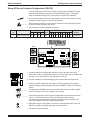
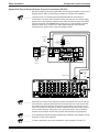
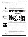
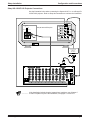
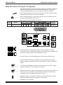
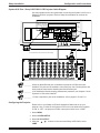
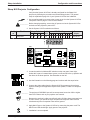
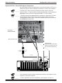
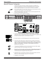
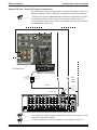
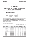
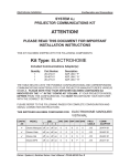
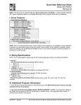
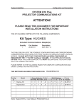
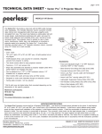
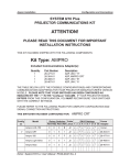
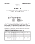
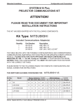
Sharp Installation
Configuration and Connections
SYSTEM 8/10 Plus
PROJECTOR COMMUNICATIONS KIT
ATTENTION!
PLEASE READ THIS DOCUMENT FOR IMPORTANT
INSTALLATION INSTRUCTIONS
THIS KIT HAS BEEN SHIPPED WITH THE FOLLOWING COMPONENTS:
Kit Type: SHARP
Included Communications Adapter(s):
Quantity
1
1
Part Number
26-426-01
26-467-01
Description
ADP, SHARP IR
ADP, UNV, “A”
THE TABLE BELOW LISTS THE POSSIBLE CONFIGURATION(S) AND CORRESPONDING
COMMUNICATIONS ADAPTER(S) FOR YOUR PROJECTOR MANUFACTURER’S VARIOUS
MODELS. PLEASE NOTE THAT YOUR SWITCHER HAS BEEN CONFIGURED AS
INDICATED BY THE “✔” IN THE “Config as” COLUMN. IF YOUR PROJECTOR MODEL
DIFFERS FROM THIS CONFIGURATION, YOU MUST RECONFIGURE YOUR SWITCHER
WITH THE CORRECT SETTINGS.
PLEASE REFER TO THE FOLLOWING PAGES FOR COMPLETE CONFIGURATION AND
SIGNAL CONNECTION INSTRUCTIONS.
THIS SWITCHER HAS BEEN CONFIGURED FOR:
Config
as
✔
Model
SHARP XG (RS-232)
Rotary Switches Cable
SW15 Settings
Comm
RS1 RS2 RS3 RS4 J2/J3 1 2 3 4 5 6 7 8 9 10 Adapter
XG (RS-232)
0
0
F
9
J2
↓ ↓ ↑ ↓ ↑ ↓ ↓ ↓ ↑ ↓ 26-467-01
XG-E1200U
1
0
F
3
J2
↑ ↓ ↑ ↓ ↑ ↓ ↓ ↓ ↑ ↓ 26-426-01
XG-1000/E1100
0
0
F
3
J2
↑ ↓ ↑ ↓ ↑ ↓ ↓ ↓ ↑ ↓ 26-426-01
XG-NV6/NV2U/NV5
2
0
F
9
J2
↑ ↓ ↑ ↓ ↑ ↓ ↓ ↓ ↑ ↓ 26-467-01
XG-NV3
1
0
F
9
J2
↑ ↓ ↑ ↓ ↑ ↓ ↓ ↓ ↑ ↓ 26-467-01
XG-P10XU
2
0
F
9
J2
↑ ↓ ↑ ↓ ↑ ↓ ↓ ↓ ↑ ↓ 26-467-01
PG-C30XU
2
0
F
9
J2
↑ ↓ ↑ ↓ ↑ ↓ ↓ ↓ ↑ ↓ 26-467-01
XG-P20XU
1
0
F
9
J2
↑ ↓ ↑ ↓ ↑ ↓ ↓ ↓ ↑ ↓ 26-467-01
Extron • System 8/10 PLUS • User’s Manual • P/N 68-409-01 Rev. C
Page 1
Sharp Installation
Configuration and Connections
Sharp XG Series Projector Configuration (RS-232)
Verify that the System 8/10 Plus is already configured for the Sharp XG Series
projector by following the procedure and switch settings below. The general
setup is explained on page 3-4 of your System 8/10 Plus User’s Manual.
1. Use a small screwdriver to remove the access cover from the System 8/10 Plus
front panel. Refer to page 3-3 of the User’s Manual.
_________ Before changing anything, remove the AC power cord to the System 8/10 Plus
and also turn the projector’s power OFF.
2. Set the System 8/10 Plus switches as follows:
Config
Model
Rotary Switches Cable
as
RS1 RS2 RS3 RS4 J2/J3
Sharp XG (RS-232)
0
0
F
9
SW15 Settings
1 2
3
4
5
6
↓ ↓ ↑ ↓ ↑ ↓
J2
Comm
7 8
9 10
↓ ↓ ↑ ↓
4
Adapter
26-467-01
¯
ON
1
2
3
4
5
6
7
8
9
10
SW15 DIP Switch
RS2
RS3
RS5 RS2 RS1
RS1
RS3 RS4
RS4
Configured For:
RS-232
3. Locate the switcher’s Address DIP switches on the rear panel, lower right.
Unless this is part of a master/slave system, set #3 and #5 to the up position and
the others in the down position. See illustration on the left.
4. Use the illustration on the following page and continue with the steps below.
5. Connect the BNC cables from the System 8/10 Plus outputs to the projector
inputs according to the application requirements (RGBS, S-Video or Composite
Video).
________ The projector’s RGB BNC input will not accept rates lower than VGA or higher
than XGA. Please refer to your projector user manual.
________ Some Sharp projectors will only select S-Video when connected to an S-Video
source. You should not input S-Video and Composite Video sources
simultaneously on these models. Consult your Sharp manual to determine if
your model supports CVID and SVID simultaneously.
6. Apply Main Power to the System 8/10 Plus by connecting the power cord. The
Main Power LED should light. Apply power to the projector.
7. Installation is now completed.
Extron • System 8/10 PLUS • User’s Manual • P/N 68-409-01 Rev. C
Page 2
Sharp Installation
Configuration and Connections
System 8/10 Plus to Sharp XG Series Projector Connections (RS-232)
Use the illustration below as a guide when connecting the System 8/10 Plus to a
Sharp projector. Refer to Sharp documentation to continue the installation.
________ Important note! For Sharp projectors which do not allow simultaneous
connections to S-Video and Composite Video (see last note on previous page),
please refer to the following diagram where either S-Video or Composite Video
may be connected, but not both at the same time. For those Sharp projectors
which will allow you to connect to S-Video and Composite Video sources
simultaneously - please refer to the inset diagram below.
Composite
Video
or
Universal
CommAdapter
26-467-01
S-Video
VIDEO INPUT
VIDEO INPUT
S-VIDEO
S-VIDEO
VIDEO
DO NOT
CONNECT
HERE
IN
2
9-Pin Female
AUDIO INPUT
PC CONTROL
MOUSE
FOR PC98
WIRED
REMOTE
VIDEO
L
IN
1
9-Pin Male
R
VIDEO OUTPUT
COMPUTER RGB
INPUT 1
OUTPUT
CONNECT
HERE
FILTER
R
INPUT 2
R
G
B
H
COMPUTER
AUDIO IN
AUDIO OUTPUT
L
V
DC5V OUTPUT
MAX CURRENT 1A
-
ON
Composite
Video
+
OFF
and
S-Video
Composite
Video
RGBHV 5 BNC
15-Pin
Male
or
S-Video
________ When RS-232 control of the projector is used, the projector’s IR remote can be
used. However, because the projector’s IR remote does not communicate with
the System 8/10 Plus switcher, the projector and switcher can become out-ofsync if the projector’s IR remote is used to change the projector’s input, picture
mute or power settings. Should this occur, press the power, mute or channel
buttons on the switcher to allow the projector and switcher to resynchronize.
________ If the installation includes looping (master/slave) switchers, see Chapter 5 of the
System 8/10 Plus User’s Manual.
________ If Video Loop Back is part of the installation, refer to pages 2-10 and 2-11.
Extron • System 8/10 PLUS • User’s Manual • P/N 68-409-01 Rev. C
Page 3
Sharp Installation
Configuration and Connections
Sharp XG-1000/E1100 Projector Configuration
Verify that the System 8/10 PLUS is already configured for the Sharp projector.
The general setup is explained on page 3-4 and the switch settings for the Sharp
projector are repeated below.
1. Use a small screwdriver to remove the access cover from the System 8/10 PLUS
front panel. See bottom of page 3-3. The label on the back of the access cover
also has the configuration information.
__________ Before changing anything, remove the AC power cord to the System 8/10 PLUS
to verify that the main power is OFF; also turn the projector power OFF.
2. Set the switches as follows:
Config
Model
as
Rotary Switches Cable
RS1 RS2 RS3 RS4 J2/J3
Sharp XG
0
0
F
3
SW15 Settings
1 2
3
4
5
6
↑ ↓ ↑ ↓ ↑ ↓
J2
Comm
7 8
9 10
↓ ↓ ↑ ↓
4
Adapter
26-426-01
¯
ON
1
2
3
4
5
6
7
8
9
10
SW15 DIP Switch
RS2
RS3
_ RS5 is for
RGB switching
delay. See
page 3-4 for
more
information.
RS5 RS2 RS1
RS1
RS3 RS4
RS4
Configured For:
RS-232
3. Use a grease pencil (or other rub-off marker) to mark the space on the label next
to “Sharp XG”.
4. Locate the switcher’s Address DIP switches on the rear panel, lower right.
Unless this is part of a master/slave system, set #3 and #5 to the up position and
the others down. See picture to the left.
Use the illustration on the next page to do the following steps.
5. Connect the Comm Adapter’s miniphone connector to the “Wired Remote” input
jack and the power plug to the Aux power port on the rear panel of the projector.
6. Connect the CC-50' (or CC-100') cable from the 9-pin male connector of the
Comm Adapter to the 15-pin HD “Projector Control” port located on the rear
panel of the System 8/10 PLUS. (If you wish to make your own communications
cable, see page 3-2.)
______ Secure the screws on all D connectors.
7. Connect the BNC cables from the System 8/10 PLUS outputs to the Sharp
projector inputs according to the application requirements.
8. Apply Main Power to the System 8/10 PLUS by connecting the power cord. The
Main Power LED should light. Apply power to the projector.
9. Return System 8/10 PLUS and projector to normal operation.
Extron • System 8/10 PLUS • User’s Manual • P/N 68-409-01 Rev. C
Page 4
Sharp Installation
Configuration and Connections
Sharp XG-1000/E1100 Projector Connections
Use the illustration below when connecting the System 8/10 PLUS to a Sharp XG1000/E1100 projector. Refer to Sharp documentation to continue the installation.
Filter
ON
ANALOG
OFF
Sharp XG-1000 or E1100 Projector
DIGITAL
INPUT
1
AUDIO
R
L
VIDEO
S-VIDEO
WIRED
REMOTE
INPUT
2
COMPUTER RGB INPUT
C-SYNC
OUTPUT
COMPUTER RGB OUTPUT
RGB INPUT
15-Pin
AUDIO
R
G
15.75kHz/15.625kHz
B
ANALOG RGB
DC12V
OUTPUT
MAX CURRENT
200mA
-
+
red
cable
Sharp COM
Adapter
26-426-01
9-Pin
CC 50'
15-Pin
________ If the installation includes looping (master/slave) switchers, see Chapter 5.
If Video Loop Back is part of the installation, see pages 2-10 and 2-11.
Extron • System 8/10 PLUS • User’s Manual • P/N 68-409-01 Rev. C
Page 5
Sharp Installation
Configuration and Connections
Sharp XG-E1200U LCD Projector Configuration
Verify that the System 8/10 Plus is already configured for the Sharp XG-E1200U
projector by following the procedure and switch settings below. The general
setup is explained on page 3-4 of your System 8/10 Plus User’s Manual.
1. Use a small screwdriver to remove the access cover from the System 8/10 Plus
front panel. Refer to page 3-3 of the User’s Manual.
___________ Before changing anything, remove the AC power cord to the System 8/10 Plus
and also turn the projector’s power OFF.
2. Set the System 8/10 Plus switches as follows:
Config
Model
Rotary Switches Cable
as
SW15 Settings
RS1 RS2 RS3 RS4 J2/J3
Sharp XG-E1200U
0
0
F
3
4
1 2
3
4
5
6
↑ ↓ ↑ ↓ ↑ ↓
J2
ON
1
2
3
4
5
6
7
8
Comm
7 8
9 10
↓ ↓ ↑ ↓
9
Adapter
26-426-01
¯
10
SW15 DIP Switch
RS2
RS3
RS5 RS2 RS1
RS1
RS3 RS4
RS4
Configured For:
RS-232
3. Locate the switcher’s Address DIP switches on the rear panel, lower right.
Unless this is part of a master/slave system, set #3 and #5 to the up position and
the others in the down position. See illustration on the left.
4. Use the illustration on the following page and continue with the steps below.
5. Connect the BNC cables from the System 8/10 Plus outputs to the projector
inputs according to the application requirements (RGBS, S-Video or Composite
Video).
________ The projector’s RGB BNC input will not accept rates lower than VGA or higher
than XGA. Please refer to your projector user manual.
________ Because the projector’s video port will only select S-Video when connected to an
S-Video source, you should not input S-Video and Composite Video sources
simultaneously since Composite Video will be ignored.
6. Apply Main Power to the System 8/10 Plus by connecting the power cord. The
Main Power LED should light. Apply power to the projector.
7. Installation is now completed.
Extron • System 8/10 PLUS • User’s Manual • P/N 68-409-01 Rev. C
Page 6
Sharp Installation
Configuration and Connections
System 8/10 Plus - Sharp XG-E1200U LCD Projector Cable Diagram
Use the illustration below as a guide when connecting the System 8/10 Plus to a
Sharp XG-E1200U projector. Refer to Sharp documentation to continue the
installation.
VIDEO INPUT
S-VIDEO
VIDEO
AUDIO INPUT
L
PC CONTROL
MOUSE
FOR PC98
WIRED
REMOTE
R
COMPUTER
INPUT 1
VIDEO OUTPUT
RGB
AUDIO OUTPUT
OUTPUT
L
ON
R
OFF
G
B
COMPUTER
AUDIO IN
R
DC5V OUTPUT
MAX CURRENT 1A
INPUT 2
FILTER
See first
note below
➶
➶
To S-Video source or
BNC-to-S-Video adapter
(26-353-01, male-to-male)
H
V
-
+
➶
Power Plug
Adapter (26-446-01)
SHARP COM
ADAPTER 26-426-01
VIDEO INPUT
VIDEO
➶
S-VIDEO
To Composite Video source (see last note on previous page)
________ When the Wired Remote jack is installed, the projector’s IR Receivers are
disabled. This jack can be installed or removed at any time. Please perform the
basic projector setup before installing the Wired Remote jack.
________ If the installation includes looping (master/slave) switchers, see Chapter 5 of the
System 8/10 Plus User’s Manual.
________ If Video Loop Back is part of the installation, refer to pages 2-10 and 2-11.
Configuring the Projector
Please refer to your Sharp XG-E1200U Operations Manual to set up your
projector. Also, in order for the System 8/10 Plus to know whether the projector
is “ON” or “OFF”, the projector’s 5VDC output jack must be set to “LAMP”.
1. Select MENU.
2. Select SYSTEM SETUP.
▲
4. Using the
LAMP.
▲
3. Select DC 5V OUTPUT.
buttons on the rear of the Sharp XG-E1200U, select
Extron • System 8/10 PLUS • User’s Manual • P/N 68-409-01 Rev. C
Page 7
Sharp Installation
Configuration and Connections
Sharp NV6 Projector Configuration
Verify that the System 8/10 Plus is already configured for the Sharp NV6
projector by following the procedure and switch settings below. The general
setup is explained on page 3-4 of your System 8/10 Plus User’s Manual.
1. Use a small screwdriver to remove the access cover from the System 8/10 Plus
front panel. Refer to page 3-3 of the User’s Manual.
__________ Before changing anything, remove the AC power cord to the System 8/10 Plus
and also turn the projector’s power OFF.
2. Set the System 8/10 Plus switches as follows:
Config
Model
as
Rotary Switches Cable
SW15 Settings
RS1 RS2 RS3 RS4 J2/J3
Sharp NV6
2
0
F
9
1 2
3
4
5
6
↑ ↓ ↑ ↓ ↑ ↓
J2
4
Comm
7 8
9 10
↓ ↓ ↑ ↓
Adapter
26-467-01
¯
ON
1
2
3
4
5
6
7
8
9
10
SW15 DIP Switch
RS2
RS3
RS5 RS2 RS1
RS1
RS3 RS4
RS4
Configured For:
RS-232
3. Locate the switcher’s Address DIP switches on the rear panel, lower right.
Unless this is part of a master/slave system, set #3 and #5 to the up position and
the others in the down position. See illustration on the left.
4. Use the illustration on the following page and continue with the steps below.
5. Connect the video cables from the System 8/10 Plus outputs to the projector
inputs according to the application requirements (RGBS, S-Video or Composite
Video).
________ The projector’s RGB BNC input will not accept rates lower than VGA or higher
than XGA. Please refer to your projector user manual.
________ Because the projector’s video port will only select S-Video when connected to an
S-Video source, you should not input S-Video and Composite Video sources
simultaneously since Composite Video will be ignored.
6. Apply Main Power to the System 8/10 Plus by connecting the power cord. The
Main Power LED should light. Apply power to the projector.
7. Installation is now completed.
Extron • System 8/10 PLUS • User’s Manual • P/N 68-409-01 Rev. C
Page 8
Sharp Installation
Configuration and Connections
System 8/10 Plus - Sharp NV6 Projector Connections
Use the illustration below as a guide when connecting the System 8/10 Plus to a
Sharp NV6 projector. Refer to Sharp documentation to continue the installation.
________ Important note! When connecting the Switcher’s BNC output to either the
projector’s BNC or 15-pin input (but not both simultaneously), set the projector’s
input type selector switch to the appropriate “BNC” or “15-pin” setting.
○
○
○
○
○
○
________ The Sharp NV6 projector does not allow simultaneous connections to S-Video
and Composite Video (see last note on previous page), please refer to the
following diagram where either S-Video or Composite Video may be connected,
but not both at the same time.
○
○
○
○
○
○
○
○
○
○
○
○
input type
selector switch
Sharp NV6 Connect.eps
Universal
CommAdapter
26-467-01
○
○ ○
○
○
○ ○
○
○
○ ○
○
○
○
○
○
Sharp RS-232C cable
Important note!
Composite Video and S-video
output to the projector may not
be connected simultaneously
9-Pin Female
9-Pin Male
CC cable
Composite
Video
15-Pin
Male
or
S-Video
RGBHV 5 BNC
________ If the installation includes looping (master/slave) switchers, see Chapter 5 of the
System 8/10 Plus User’s Manual.
________ If Video Loop Back is part of the installation, refer to pages 2-10 and 2-11.
Extron • System 8/10 PLUS • User’s Manual • P/N 68-409-01 Rev. C
Page 9
Sharp Installation
Configuration and Connections
Sharp NV3 Projector Configuration
Verify that the System 8/10 Plus is already configured for the Sharp NV3
projector by following the procedure and switch settings below. The general
setup is explained on page 3-4 of your System 8/10 Plus User’s Manual.
1. Use a small screwdriver to remove the access cover from the System 8/10 Plus
front panel. Refer to page 3-3 of the User’s Manual.
__________ Before changing anything, remove the AC power cord to the System 8/10 Plus
and also turn the projector’s power OFF.
2. Set the System 8/10 Plus switches as follows:
Config
Model
as
Rotary Switches Cable
SW15 Settings
RS1 RS2 RS3 RS4 J2/J3
Sharp NV3
1
0
F
9
4
1 2
3
4
5
6
↑ ↓ ↑ ↓ ↑ ↓
J2
ON
1
2
3
4
5
6
7
8
9
Comm
7 8
9 10
↓ ↓ ↑ ↓
10
Adapter
26-467-01
¯
SW15 DIP Switch
RS2
RS3
RS5 RS2 RS1
RS1
RS3 RS4
RS4
Configured For:
RS-232
3. Locate the switcher’s Address DIP switches on the rear panel, lower right.
Unless this is part of a master/slave system, set #3 and #5 to the up position and
the others in the down position. See illustration on the left.
4. Use the illustration on the following page and continue with the steps below.
5. Connect the video cables from the System 8/10 Plus outputs to the projector
inputs according to the application requirements (RGBS, S-Video or Composite
Video). One end of the Universal Comm adapter plugs into the IOIOI port of the
Sharp PC Control adapter. The Sharp PC Control adapter plugs into the
projector’s PC Control port 1.
________ The projector’s RGB BNC input will not accept rates lower than VGA or higher
than XGA. Please refer to your projector user manual.
________ Because the projector’s video port will only select S-Video when connected to an
S-Video source, you should not input S-Video and Composite Video sources
simultaneously since Composite Video will be ignored.
6. Apply Main Power to the System 8/10 Plus by connecting the power cord. The
Main Power LED should light. Apply power to the projector.
7. Installation is now completed.
Extron • System 8/10 PLUS • User’s Manual • P/N 68-409-01 Rev. C
Page 10
Sharp Installation
Configuration and Connections
System 8/10 Plus - Sharp NV3 Projector Connections
Use the illustration below as a guide when connecting the System 8/10 Plus to a
Sharp NV3 projector. Refer to Sharp documentation to continue the installation.
________ The Sharp NV3 projector does not allow simultaneous connections to S-Video
and Composite Video (see last note on previous page), please refer to the
following diagram where either S-Video or Composite Video may be connected,
but not both at the same time.
○
○
○
PC Control port 1
Sharp PC Control adapter
Universal
CommAdapter
26-467-01
○ ○ ○ ○ ○ ○ ○ ○ ○ ○ ○ ○ ○ ○ ○ ○ ○ ○ ○ ○ ○ ○ ○ ○ ○ ○ ○ ○ ○ ○ ○ ○ ○ ○ ○
○
○ ○ ○ ○ ○ ○ ○ ○ ○ ○ ○ ○ ○ ○ ○ ○ ○ ○ ○ ○ ○ ○ ○ ○ ○ ○ ○ ○ ○ ○ ○ ○ ○
○ ○ ○ ○ ○ ○ ○ ○ ○ ○ ○ ○ ○ ○ ○ ○ ○
○ ○ ○ ○ ○ ○ ○ ○ ○ ○ ○ ○ ○ ○ ○ ○ ○ ○ ○ ○ ○ ○ ○ ○ ○ ○ ○ ○ ○ ○ ○ ○ ○ ○ ○ ○ ○ ○ ○ ○ ○
9-Pin Female
See
note
above
9-Pin Male
CC cable
Composite
Video
15-Pin
Male
or
S-Video
RGBHV 5 BNC
________ If the installation includes looping (master/slave) switchers, see Chapter 5 of the
System 8/10 Plus User’s Manual.
________ If Video Loop Back is part of the installation, refer to pages 2-10 and 2-11.
Extron • System 8/10 PLUS • User’s Manual • P/N 68-409-01 Rev. C
Page 11