1
RM2351 RM2510 DM2662
RM2354 RM2551 DM2663
RM2410 RM2554 RM3762
RM2451 RM2620 RM2820
RM2454 DM2652 DM2852
FOR YOUR SAFETY
DM2862
RM3962
NDM1062
RM1350
NDA1402
If you smell gas:
1. Open windows.
2. Don’t touch electrical switches.
3. Extinguish any open flame.
4. Immediately call your gas supplier.
INSTALLATION
INSTRUCTIONS
PAR MESURE DE SÉCURITÉ
Si on détecte une odeur de gaz :
1.Ouvrir les fenêtres.
2.Ne pas toucher les commutateurs
électriques.
3.Éteindre toute flamme nue.
4.Contacter immédiatement le fournisseur
de gaz.
FOR YOUR SAFETY
PAR MESURE DE SÉCURITÉ
Do not store or use gasoline or other flammable vapors and liquids in the vicinity of
this or any other appliance.
Ne pas entreposer ou utiliser de l’essence
ou autre vapeur ou liquide inflammable au
voisinage de cet appareil ou de tout autre
appareil ménager.
Improper installation, adjustment,
alteration, service or maintenance can cause
injury or property damage. Refer to this manual. For assistance or additional information
consult a qualified installer, service agency
or the gas supplier.
If the refrigerator stops cooling - or - if
it emits an ammonia smell, immediately
turn the refrigerator off and contact a
Service Center.
! AVERTISSEMENT
Une installation, un réglage, une modification,
un dépannage ou un entretien effectués
incorrectement, peuvent provoquer des
blessures ou des dommages matériels.
Se reporter à ce manuel. Pour obtenir une
aide ou des informations complémentaires,
consulter un installateur qualifié, une
entreprise de dépannage ou le fournisseur
de gaz.
! AVERTISSEMENT
Si le réfrigérateur cesse de refroidir - ou - s’il
s’en dégage une odeur d’ammoniac, arrêter
immédiatement le réfrigérateur et contacter
un centre de service après-vente.
3313238.036
REVISION
Form No. 3313238.036 7/11
(Replaces 3313238.028)
(French 3313239.034)
©2011 Dometic, LLC
LaGrange, IN 46761
USA
Dometic, LLC
Service Office
2320 Industrial Pkwy.
Elkhart, IN 46516
Phone: 574-294-2511
CANADA
Dometic, LLC
48 Zatonski, Unit 3
Brantford, ON N3T 5L8
CANADA
Phone: 519-720-9578
Corporate Office
2320 Industrial Parkway
Elkhart, IN 46516
For Service Center
Assistance
Call: 800-544-4881
NOTES
-2-
CONTENTS
CERTIFICATION AND CODE REQUIREMENTS................................................................................. 4
INSTALLATION PREPARATION.......................................................................................................... 5
VENT APPLICATION TYPES............................................................................................................. 8
INSTALLATION PROCEDURE.......................................................................................................... 13
REFRIGERATOR REMOVAL............................................................................................................. 27
APPENDIX A - OVERALL & ROUGH IN DIMENSIONS FOR ENCLOSURE..................................... 28
APPENDIX B - MINIMUM VENTILATION HEIGHTS......................................................................... 29
APPENDIX C - APPROVED VENTS.................................................................................................. 30
APPENDIX D - VENT INSTALLATION PROCEDURES..................................................................... 34
APPENDIX E - REARVIEW EQUIPMENT.......................................................................................... 35
APPENDIX F - WIRING DIAGRAMS................................................................................................. 42
SYMBOLS
The following symbols are used throughout this manual:
This is the safety alert symbol. It is used to alert you to personal injury hazards. Obey all safety
messages that follow this symbol to avoid possible injury or death.
WARNING indicates a hazardous situation which, if not avoided, could result in death or serious injury.
CAUTION, used with the safety alert symbol, indicates a hazardous situation which, if not avoided,
could result in minor or moderate injury. NOTICE is used to address practices not related to personal injury.
Information
Step-by-step instructions
-3-
INTRODUCTION
The installation should be performed by qualified personnel only and must conform to all relevant local authorities. Be aware of possible safety hazards when seeing alert symbols on the refrigerator as well as in this manual.
To ensure safe and efficient operation, the refrigerator and vents must be installed as identified in this manual
without modification. The installer must affix the refrigerator model’s user manual to the refrigerator.
Any modifications or deviations:
• Can lead to carbon monoxide leaking into the
living area.
• Can reduce cooling performance and/or result in
damage to the refrigerator.
• Will void agency certifications.
• Will void refrigerator warranty.
Any deviation from the prescribed installation
instructions in this manual must have prior written
approval and safety certification verification from
Dometic, LLC.
CERTIFICATION AND CODE REQUIREMENTS
This appliance is certified under the latest edition of ANSI Z21.19•CSA 1.4 Refrigerators using gas fuel. The installation must
conform with local codes, or in absence of local codes, the following standards as applicable.
In the U.S. the installation must conform with:
•National Fuel Gas Code, ANSI Z223.1/NFPA 54
(latest edition).
•Recreational Vehicles Code, ANSI A119.2 (latest edition).
•Manufactured Home Construction and Safety Standard,
Title 24 CFR, Part 3280.
In CANADA, the installation must conform with:
•Natural Gas and Propane Installation Code, CSA B149.1
•CSA Z240 RV Series, Recreational Vehicles.
•Current CSA Z240.4, Gas-equipped Recreational Vehicles
and Mobile Housing.
If an external electrical service is utilized, the refrigerator,
when installed, must be electrically grounded in accordance
with local codes or, in the absence of local codes, the Canadian Electrical Code CSA C22.1, Parts Ι and ΙΙ - (latest edition).
If an external electrical source is utilized, the refrigerator,
when installed, must be electrically grounded in accordance
with local codes or, in the absence of local codes, the National
Electrical Code, ANSI/NFPA 70 - (latest edition).
-4-
INSTALLATION PREPARATION
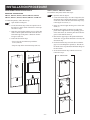
ASSEMBLING THE
REFRIGERATOR ENCLOSURE
-- OEM installed components inside of the refrigerator
enclosure are contained outside of the ventiliation compartment by means of permanently securing them (e.g.
behind paneling, behind batt-type insulation, inside of
paneled storage space above refrigerator) in such a manner that OEM installed components will not come into
contact with the refrigerator.
-- Applications for which there are no alternatives except
to have these OEM installed components pass through
the ventilation compartment the following requirements
must be met: 1) current carrying conductors (120V and
12V) and conductor routing - except for those required
to supply the refrigerator - must be protected by conduit,
raceway, covering boards or equilvalent and in all cases
must meet or exceed the requirements of the current
publication of NFPA70 and article 551 of the NEC, 2)
all OEM installed components shall maintain a minimum clearance of 1/2" clearance from the cooling unit
to ensure that they will not come into contact with the
heated boiler or tubing, 3) the routing of OEM installed
components shall not impede the ventilation path for
proper operation or combustion, 4) OEM installed components must not come into contact with the refrigerator
mounting rails or frame and the refrigerator should not
be modified in any way to accommodate the location or
routing of OEM installed components.
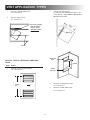
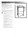
The ventilation compartment is part of the product
safety certification and must not be used for any other
purpose than securing air for combustion and ventilation of flue gases and warm air.
Ventilation
Compartment
Enclosure
Refrigerator
FIG 1 - ENCLOSURE
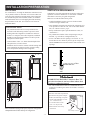
Read and follow these points:
•The refrigerator must be level and installed in a substantial
enclosure, see “APPENDIX A”.
•The floor must be solid and level and able to support the
weight of the refrigerator and its contents.
•Ensure that any adjacent heat sources, (e.g. furnace exhaust
vent) do not affect the ventilation of the refrigerator.
•All joints in the enclosure must be sealed to prevent gas
leakage into the living area.
•The enclosure must be free of exposed materials that may
potentially damage the refrigerator, e.g. screw tips, staples,
etc.
•A wood strip must be in place across the upper opening
of the enclosure. The top frame of the refrigerator will be
anchored to the wood strip with screws, see FIG 2.
•The refrigerator must not be installed directly on
carpeting:
-- Carpeting must be removed or protected by a metal or
wood panel beneath the appliance, which extends at least
full width and depth of the appliance.
-- If the refrigerator is sitting on a wood floor, the exposed
portion behind the refrigerator will need to be painted
with an anti-wicking paint to protect against water or
moisture that comes in through the side or roof vent.
•It is required that OEM installed components such as
current-carrying conductors (i.e. wiring), plumbing, etc. except for those required to supply the refrigerator - shall
not pass through the refrigerator enclosure except where:
Failure to adhere to the above installation criteria could create a combustion hazard.
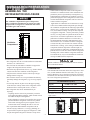
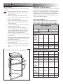
CLEARANCES
CSA International certification allows the refrigerator to have
zero (0) inch minimum clearance at the sides, rear, top, and
bottom. While there are no maximum clearances specified for
certification, the maximum clearances specified are necessary
for correct refrigerator performance.
CLEARANCES (FIG 2)
Top (G)
Side (K)
Bottom (L)
Rear (M1)
1
0” Min to 1/4” Max
0” Min to 1/4” Max
0” Min to 0” Max
0” Min to 1” Max
The distance between the refrigerator cooling unit and the wall or
baffle behind it.
FIG 2 - CLEARANCES
G
K
Wood
Strip
K
M
L
-5-
INSTALLATION PREPARATION
VENTILATION REQUIREMENTS
TOP AND SIDES
See “APPENDIX A” for rough in dimensions. Dimensions will
vary by model. If there is more than 1/4” between either side
or the top of the refrigerator and the inside of the refrigerator
box, then fill the space with insulation, baffles, or non-flammable fabricated seals to avoid trapping heat and sacrificing
the performance of the unit. See Insulation note below for
additional details.
Ventilation is one of the requirements for proper cooling unit
operation. Clearances and the use of vents ensure a natural
draft which is necessary for good refrigeration.
Make sure to read and follow these points:
•Certified installation requires one lower fresh air intake
vent and one upper exhaust vent.
•Vents should be centered to the back of the refrigerator. If it
is not possible to center the vent, refer to the offset installation, see “OFFSET VENTS”, page 8.
•Safety certification requires specified Dometic vents, see
“APPENDIX C”.
•Any obstruction of either of the vent openings is not permissible, e.g. roof rafters, roofing materials, etc.
•Lower vent: Make sure the opening is even with - or - below the floor level to allow any raw LP gas to escape to the
outside. NOTE! Floor must not interfere with or block vent
openings.
INSULATION NOTE!
-- Any insulation used must be securely attached to the
enclosure walls and ceiling in order to prevent it from
shifting when the refrigerator is installed in enclosure.
-- If there is a void space above the refrigerator, insulation
should be secured with spray adhesive to the top of the
refrigerator to fill the space.
-- Trim insulation. Cut it 2-3” shorter than the depth of the
refrigerator box, see FIG 3 below.
-- Insulation must not come in contact with the cooling unit!
Loose insulation can obstruct air flow creating cooling
issues and possible damage to the refrigerator.
FIG 3 - INSULATION
FIG 4 - LOWER VENT
2” - 3”
Floor
Weep
hole
Side
wall
COMBUSTION HAZARD. Unburned “Raw” LP
gas is heavier-than-air and can collect at floor level
creating a combustion hazard.
•For vents installed above floor level, additional holes are
required to vent these gases to the out-of-doors. Use FIG 5
for details.
FIG 5 - VENT ABOVE FLOOR LEVEL
When lower vent frame is positioned
higher than the refrigerator compartment floor, the following is required:
•2 holes with a diameter of 1-3/4”
1 in2 / hole free area.)
2” - 3”
•Cover holes with a screen
(min. 14 x 14 per inch)
•Holes must be clear of any
obstruction.
Place insulation filling in the space between refrigerator
compartment and sides and top of refrigerator.
-6-
1-3/4”
Covered by a screen
INSTALLATION PREPARATION
•The flow of combustion and ventilating air must not be
obstructed, e.g. by an open RV door.
•Do not install an awning too close to the upper side vent.
Allow a distance of approx. 6-12”.
•The minimum vent height requirements, listed in “APPENDIX B”, are part of the safety certification and must be
complied with.
If there is more than 1” between the inside of the ventilation compartment and cooling unit, it is required to add box
baffle(s) starting above the lower access vent and running perpendicular to the side wall. The baffle should extend up to the
ceiling (in board roof vent vent applications) or up to within
1/2” lower than the condenser fins (roof vent applications). For
upper and lower side wall vent applications the baffle should
come within 1/2" lower than the condenser fins. This will
ensure more efficient operation in warm temperatures. Make
sure the baffle is of the same width as the ventilation compartment, see FIG 7.
RECESS DEPTH
Spaces of more than 1”, see FIG 6, from rear wall to the refrigerator may create performance problems. Fresh air will not
pass through the cooling unit which will reduce the efficiency.
It is important to check the recess depth and add baffle(s) to
increase the movement of air across the coil.
FIG 7 - BOX BAFFLE
Roof Vent Applications
Inboard Roof Vent
Applications
FIG 6 - RECESS DEPTH
BOX BAFFLE
BOX BAFFLE
1/2" Below
Fins
Max 1”
(without
baffle)
WATER SUPPLY CONNECTION
REFRIGERATOR MODELS EQUIPPED WITH ICE MAKER, ICE
AND WATER DISPENSERS
The water supply system must have a minimum pressure of
15 pounds per square inch gauge (psig). A 1/4” diameter water
line to the water valve should be used at the rear of the refrigerator. The water line must have a manual shutoff valve placed
where it is easily accessible.
-7-
INSTALLATION PREPARATION
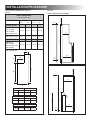
OFFSET VENTS
If vents must be offset due to interference of building
materials the vent must always be offset towards the flue side
of the cooling unit. The vent should be centered over the cooling unit so that the air can flow up and out of the compartment
creating a chimney effect. For offset vent applications, prior
written approval and safety certification must be obtained from
Dometic, LLC.
FIG 9 - OFFSET VENT
SIDE AND ROOF VENT
FIG 8 - OFFSET VENT
UPPER AND LOWER SIDE VENT
CENTER OF
REFRIGERATOR
CENTER OF
REFRIGERATOR
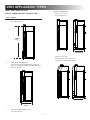
VENT APPLICATION TYPES
CHOOSING TYPE OF VENT APPLICATION
There are four types of applications:
•ROOF VENT APPLICATION
Recommended for typical installations. Check the enclosure depth, see “INSTALLATION PREPARATION > ENCLOSURE DEPTH” and add a baffle if required. Roof vent installations can also be used when vents are inboard or offset
due to radius roof or interference with building materials.
•ISLAND APPLICATION
Intended for refrigerators installed on an inside wall and
must be vented through the floor to the ceiling.
•CORNER APPLICATION
Intended for refrigerators installed in the rear corner of the
vehicle or in an angled cabinet. The refrigerator must be
equipped with fan(s).
•UPPER AND LOWER SIDE VENT APPLICATION
Choose this type of installation when a roof vent installation is not possible. Baffle should be added. The refrigerator must be equipped with fan(s).
Please refer to page 30, some fans are optional and not
required.
-8-
VENT APPLICATION TYPES
ROOF VENT APPLICATION
4
Step
See “APPENDIX D”.
Action
CHECK VENTILATION HEIGHT.
See “APPENDIX B”.
BOX BAFFLE
1
INSTALL ROOF VENT
•Option 1 - Typical
INSTALL LOWER SIDE VENT AND ROOF VENT
Minimum
Ventilation
Height
RECESS DEPTH
•Option 2 - Inboard
BOX BAFFLE
CHECK RECESS DEPTH.
See “INSTALLATION PREPARATION > RECESS
DEPTH”. If required, install a box baffle above the
lower access vent.
BOX BAFFLE
2
Inboard installs due to radius roof or
interference with building material.
RECESS DEPTH
RECESS
DEPTH
3
INSTALL LOWER SIDE VENT
See “APPENDIX D”.
-9-
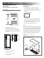
VENT APPLICATION TYPES
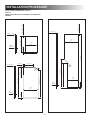
UPPER AND LOWER SIDE VENT
APPLICATION
ISLAND APPLICATION
ACCESS PANEL
•A sealed access panel is required when using this
system in conjunction with below floor ventilation.
Access is necessary to complete gas connections, gas leak
tests, and periodic service requirements at the rear of the
refrigerator.
INSTALL UPPER AND LOWER SIDE VENTS
Step
1
Action
CHECK VENTILATION HEIGHT.
See “APPENDIX B”.
Access panel dimensions
14”
22”
Minimum
Ventilation
Height
Fan(s)*
•If the refrigerator is located within the vehicle interior it
must be completely sealed to prevent products of combustion or raw gas leakage within the living space! If it
is placed alongside the sidewall and floor ventilation is
provided, rear access is still required.
•The door or panel should prevent water entry.
DUCT
An air duct extends downwardly from the refrigerator through
a floor of the vehicle. If the refrigerator is not equipped with
a fan, a fan must be installed in the duct to aid air circulation.
Air for cooling the condenser and absorber is drawn up the
duct from outside the vehicle and exhausted outside the vehicle through an upper duct and vent in a roof of the vehicle.
The duct must be centered horizontally on the back of the
refrigerator and should have the following dimensions:
* Fan(s) position may vary by model.
2
CHECK RECESS DEPTH.
See “INSTALLATION PREPARATION >
RECESS DEPTH”. If required, install a box baffle above the lower access vent extending within
1/2” lower than the condenser fins as shown in the
picture below.
Length (L): 11-34” min - max values
Width (W): 6.5”
Depth (D): 4-54” min - max values
FIG 10 - DUCT DIMENSIONS
BOX BAFFLE
L
Center Fan
Horizontally
Min 3”
Max 8”
D
RECESS
DEPTH
3
4
INSTALL UPPER SIDE VENT.
See “APPENDIX D”.
W
1/4
INSTALL LOWER SIDE VENT.
See “APPENDIX D”.
”x
- 10 -
0.0
25
me
tal
me
sh
VENT APPLICATION TYPES
ISLAND APPLICATION CONT'D
INSTALL DUCT AND ROOF VENT
Step
1
Action
CHECK VENTILATION HEIGHT.
See “APPENDIX B”.
3
INSTALL ACCESS PANEL
4
INSTALL DUCT
5
INSTALL ROOF VENT
See “APPENDIX D”.
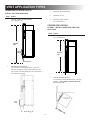
CORNER APPLICATION
OPTION 1 - INSTALL LOWER SIDE VENT AND
ROOF VENT
Step
1
Action
CHECK VENTILATION HEIGHT.
See “APPENDIX B”.
Minimum
Ventilation
Height
{
Minimum
Ventilation
Height
ACCESS
PANEL
DUCT AND FAN
2
CHECK RECESS DEPTH.
See “INSTALLATION PREPARATION > RECESS
DEPTH”. If required, install a box baffle above the
lower access vent. Box baffle must be positioned no
lower than access panel.
2
CHECK RECESS DEPTH.
See “INSTALLATION PREPARATION > RECESS
DEPTH”. A box baffle is required above the
lower access vent.
ACCESS
PANEL
DUCT
AND
FAN
RE
DE CES
PT S
H
RECESS DEPTH
- 11 -
VENT APPLICATION TYPES
3
INSTALL LOWER SIDE VENT.
See “APPENDIX D”.
4
INSTALL ROOF VENT
See “APPENDIX D”.
2
CHECK RECESS DEPTH.
See “INSTALLATION PREPARATION > RECESS DEPTH”. A box baffle is required above
the lower access vent.
Roof vent opening
must be a minimum of 110 in2
unobstructed free
area.
RE
DE CES
PT S
H
Rafters
UPPER SIDE
VENT
OPTION 2 - INSTALL UPPER AND LOWER SIDE
VENTS
Step
1
BAFFLE
Action
CHECK VENTILATION HEIGHT.
See “APPENDIX B”.
Minimum
Ventilation
Height
LOWER
SIDE VENT
3
Fan*
4
* Fan position may vary by model.
- 12 -
INSTALL LOWER SIDE VENT.
See “APPENDIX D”.
INSTALL UPPER SIDE VENT.
See “APPENDIX D”.
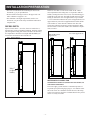
INSTALLATION PROCEDURE
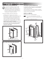
INSTALLING THE REFRIGERATOR
SECURING THE REFRIGERATOR
It is important to follow the sequence in securing refrigerator
in enclosure since failure in doing so can cause leakage between the frame and cabinet.
After the refrigerator is put in place (ensuring a combustion
seal at the front frame), the refrigerator is to be secured in the
enclosure with screws (not included).
Be careful when installing the refrigerator model
NDM1062. It is equipped with the latest vacuum
insulated panel technology. The insulating panels are
located on the top, back, bottom, sides and doors. If
the surface is punctured, loss of insulation will occur,
resulting in poor refrigerator performance.
RM2351 & RM2354
For a proper installation, follow these instructions:
Install the five screws in the following order:
•Carefully place the refrigerator in the enclosure.
1. Four screws installed through the front frame.
(To cover the screw heads, use the plugs in the parts
bag.)
2. One screw installed in the rear base.
•Verify that there is a complete seal between the front frame
of the refrigerator and the top, sides and bottom of the
enclosure. A length of sealing strip is applied to the rear
surface of the front frame for this purpose. The sealing
strip should provide a complete isolation of the appliance’s
combustion system from the vehicle interior.
RM2351, RM2354, RM2410 and RM2510: Apply a sealing strip to the foremost floor of the enclosure, see FIG 11.
Be careful not to damage the sealing strip when the
refrigerator is put in place!
FIG 13 - SECURING RM2351 & RM2354
FIG 11 - RM2351, RM2354, RM2410 & RM2510
2
1
Apply sealing strip along floor here.
Sealing strip must be width of enclosure.
Sealing
Strip
FIG 12 - RM2451, RM2454, RM2551, RM2554, DM2652, DM2662,
DM2663, DM2852, DM2862, NDM1062, RM1350 & NDA1402
General view. Features may vary by model.
- 13 -
INSTALLATION PROCEDURE
RM2410 & RM2510
RM2620 & RM2820
Install the six screws in the following order:
1. Two screws installed through the front base.
2. Two screws installed in the top frame.
3. Two screws installed in the rear base.
Install the screws in the following order:
1. Two screws installed through the front base.
2. Two screws installed in the top frame.
3. Two screws installed in the rear base.
4. Attach lower front strip after the refrigerator is set
into the cutout opening.
FIG 14 - SECURING RM2410 & RM2510
FIG 15 - SECURING RM2620 & RM2820
2 nd.
3 rd.
3 rd.
2 nd.
1 st.
1 st.
Sealing
Strip
4 th.
- 14 -
INSTALLATION PROCEDURE
RM2451, RM2454, RM2551, RM2554,
DM2652, DM2662, DM2663, DM2852,
DM2862, RM3762, RM3962, RM1350,
NDA1402 & NDM1062
b) Secure the refrigerator and the lower front
strip with two screws.
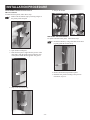
Install the screws in the following order:
1. TWO SCREWS INSTALLED THROUGH THE
FRONT BASE.
The refrigerator is provided with a lower front strip
(shipped as a loose part). Attach the front strip after
the refrigerator is set into the cutout opening.
a) Install the lower front strip by sliding it under the
bottom hinge plate(s).
Models with 1 Hinge Plate
One screw through the hinge and
on the opposite side and then, one
screw through the lower front strip.
Models with 1 Hinge Plate
The hinge plate can be located on
the left or right side depending
on the door swing. Slip under the
hinge and swing into place.
Models with 2 Hinge Plates
One screw through each hinge.
Models with 2 Hinge Plates
- 15 -
INSTALLATION PROCEDURE
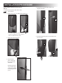
2. TWO SCREWS INSTALLED IN THE TOP
FRAME.
3. ONE SCREW INSTALLED IN THE REAR BASE.
OPTIONAL SCREW MAY BE ADDED.
RM2451, RM2454, RM2551, RM2554, DM2652,
DM2662, DM2663, DM2852, DM2862 & NDM1062
RM2451, RM2454, RM2551, RM2554, DM2652,
DM2662, DM2663, DM2852, DM2862, RM3762,
RM3962 & NDM1062
a) Gently push the tabs out of the hole in the hinge
with a flat blade screwdriver (both sides).
Optional
Screw
2
General view. Features may vary by model.
RM1350 & NDA1402
1
Ice Maker
Cord
(optional)
b) Carefully tilt the top decoration panel and lift to
remove from top frame. Be careful not to damage the circuit board and wires.
c) Install the two screws in the top frame, the holes
are accessible from underneath.
d) Seal the opening for the screws with aluminum
tape.
e) Replace the top decoration panel. Be careful not
to pinch the wires behind the panel. Make sure
the tabs snap back into the holes in the hinge
plate.
General view. Features may vary by model.
DRAIN WATER HOSE
•Hose must not contact the boiler casing.
•Hose must not be kinked.
•Hose must not be routed uphill at any point.
•Perforated plug must be present at end of hose.
RM3762, RM3962, RM1350 & NDA1402
Fasten the refrigerator with two screws through the
holes underneath the top decoration panel.
OPTION 1 - THROUGH FLOOR
Drill hole through flooring, see FIG 16. Seal around hole.
Check to make sure the supplied hose is long enough – if not,
installer will have to supply extra length of hose.
FIG 16 - DRAIN WATER HOSE
Hose
Boiler
casing
Hole for drain
water hose
- 16 -
General view. Features may vary by model.
INSTALLATION PROCEDURE
OPTION 2 - THROUGH VENT FRAME (PLASTIC
VENTS ONLY)
Pull end of hose through louvers in vent door. Cut hose
to length. Reinstall perforated plug.
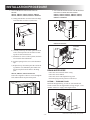
ELECTRICAL CONNECTION
120 VAC CONNECTION
The refrigerator is equipped with a grounded three-prong plug
for protection against shock hazards. It should be plugged directly into a properly grounded three-prong receptacle. Do not
cut or remove the grounding prong from this plug!
The free length of the cord is 2 feet. To allow easy access
through the vent door, it is recommended to install the receptacle on the opposite side of the burner assembly and approx.
3-6” above the refrigerator mounting floor.
OPTION 3 - HANGING CLIP (PLASTIC VENTS ONLY)
Install clip (part number 3106559.xxx) during vent installation. Insert hose into “j” portion of clip. Cut hose to length.
Reinstall perforated plug. Hose should be positioned to drain
into uppermost row of louvers in vent door.
FIG 17 - 120 VAC CONNECTION
OPTION 4 - THROUGH VENT DOOR (SIDE-BY SIDE
PLASTIC VENT ONLY)
Drill a 5/8” hole in vent frame directly above floor line. Route
drain hose through hole and cut to length. Reinstall perforated
plug on the outside of the vent frame. Apply sealant around
plug to ensure water does not seep into enclosure.
120 VAC
Receptacle
CONNECTIONS
3-6”
All connections should be routed to avoid direct
contact with boiler casing, burner cover, or any
other components of refrigerator.
General view. Features may vary by model.
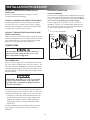
GAS CONNECTION
Hook up to the gas supply line is accomplished at the manual
gas valve, which is furnished with a 3/8” SAE (UNF 5/8” -18)
male flare connection. ALWAYS use a back-up wrench when
loosening and tightening gas connections. All completed connections should be examined for leaks using an approved leak
detection solution.
EXPLOSION HAZARD. Never use an open flame
to check for gas leaks. Failure to obey this warning could cause an explosion resulting in death or
severe personal injury.
The gas supply system must incorporate a pressure regulator
to maintain a supply pressure of not more than 11 inches water
column. When testing the gas supply system at test pressures:
•> 1/2 psi - the refrigerator and its individual shutoff valve
must be disconnected from the gas supply piping system.
•≤ 1/2 psi - the appliance must be isolated from the gas
supply piping system by closing its individual manual
shutoff valve.
If detailed instructions on the installation and connection to
the gas supply are required, please contact your dealer or
distributor.
- 17 -
INSTALLATION PROCEDURE
12 VDC CONNECTION
ALTERNATOR (D+) CONNECTION
RM2451, RM2551, DM2652, DM2852, RM3762, RM3962,
RM1350 & NDA1402: These refrigerator models are not de-
RM3762, RM3962 & RM1350 (with the automatic door
locking system)
signed for 12V DC operation of the cooling system. However,
12V DC must be supplied to operate the controls.
The refrigerator requires the connection of a signal wire from
the alternator (D+) in order to maintain the automatic door
travel latch for RM1350 and the temporary gas lockout function. The gas operation will automatically be locked out for
a period of 15 minutes when the engine is switched off. This
will prevent gas operation e.g. when stopping at a refueling
station.
Connect the vehicles alternator (D+) to the D+ on
the terminal block.
RM2354, RM2454, RM2554, DM2662, DM2663, DM2862 &
NDM1062: These refrigerator models require a continuous 12
VDC supply to maintain the automatic energy system.
The connection is made to the positive (+) and negative (-)
terminals of the terminal block on back of the refrigerator.
Correct polarity must be observed when connecting to the DC
supply. Do not use the chassis or vehicle frame as one of the
conductors. Connect two wires at the refrigerator and route to
the DC supply. Ensure the connections are clean, tight and free
from corrosion.
For 3-way models, the voltage drop affects the wattage output
of the 12 V cartridge heater and the refrigerator performance.
The 12 VDC heater is fused with a 30 amp. in-line blade fuse.
Ensure that the wires from the battery to the refrigerator are
able to handle the load. Recommended wire sizes are displayed in the table below.
D+ (Alternator signal wire)
Valid for refrigerator models
with the automatic door locking system.
FIG 18 - ALTERNATOR CONNECTION
Ignition switch
MAXIMUM WIRE LENGTH
WIRE
MODEL
RM2351, RM2451
RM2551, DM2652
DM2662, DM2852
DM2862, RM3762
RM3962, NDM1062
RM1350, NDA1402
RM2354, RM2454
RM2554, DM2663
Size
Length
AWG
ft
14
17
12
27
Charge light
Alternator signal wire to the refrigerator
D+
B+
Battery
ALTERNATOR
10
17
8
27
Example: If the distance between the refrigerator and the
12 VDC supply is 20 ft., the total wire length is 40 ft. and
a wire size of 10 AWG should be used.
- 18 -
INSTALLATION PROCEDURE
DOOR AND HANDLE MOUNTING
INSTRUCTIONS
FIG 19 - RM2410 & RM2510, REVERSING THE DOOR SWING
REVERSING THE DOOR SWING
RM2351, RM2354, RM2451, RM2454, DM2652, DM2662,
DM2663, RM2551, RM2554, RM3762, DM2852, DM2862,
RM3962, NDM1062 & NDA1402
A special hinge kit must be used in order to change the door
swing. For conversion kit number, please contact service
point or distributor service department.
RM2410 & RM2510
The refrigerator is equipped with hinges that make it possible
to change the direction the door opens by moving the hinges
to the opposite side. To change the door hinges from one side
to the other, follow these steps:
1. Open the door and remove the two screws holding the top decoration. (The screws are accessible
from beneath.)
2. Remove the top hinge pin and lift out the door.
3. Unscrew the bottom hinge pin.
4. Remove the plastic cap from the opposite lower
hinge and place it in the hole just “left empty” by
the lower hinge pin.
5. Screw the lower hinge pin in the hole from which
the plastic cap was removed.
6. Before replacing the door on the refrigerator,
remove the catches and move them to the opposite
side of the cabinet.
7. The holes are covered with plastic caps that must
be removed and inserted in the holes that previously held the catches.
8. Unscrew the handle and move it to the opposite
side of the door.
9. Insert the plastic caps into the holes left open on
the door. (Plastic caps for empty holes are in the
parts bag inside the refrigerator.)
10. Remount the door and hinge pins in the reverse
order of their removal.
11. Before the top decoration is refitted, check that the
door closes easily and the gasket seals well on all
sides.
- 19 -
INSTALLATION PROCEDURE
INSTALLING THE DOOR PANEL(S)
Before starting the mounting work, read this section thoroughly. Make sure the panel dimensions are in compliance with
those given in “PANEL DIMENSIONS”. After having mounted
the panel(s) as described in “MOUNTING INSTRUCTIONS”,
install the handles. For installation instructions for RM3762
& RM3962 (stainless steel doors) and for NDM1062, see “INSTALLING THE DOOR HANDLES”.
RM2620 & RM2820
To change the door hinges from one side to the other, follow
these steps:
1. Open the upper door and remove the two screws
holding the top decoration. (The screws are accessible from beneath.)
2. Remove the top hinge pin and lift out the door.
3. Remove center hinge pin and lift out the lower door.
4. Unscrew the bottom hinge pin.
5. Remove the plastic cap from the opposite lower
hinge and place it in the hole just “left empty” by
the lower hinge pin.
6. Screw the lower hinge pin in the hole from which
the plastic cap was removed.
7. Before replacing the doors on the refrigerator,
remove the catches and move them to the opposite
side of the cabinet. The holes are covered with
plastic caps that must be removed and inserted in
the holes that previously held the catches.
8. Unscrew the handles and move them to the opposite
side of the door.
9. Insert the plastic caps into the holes left open on the
doors. (Plastic caps for empty holes are in the parts
bag inside the refrigerator.)
10. Remount the doors and hinge pins in the reverse
order of their removal.
11. Before the top decoration is refitted, check that the
door closes easily and the gasket seals well on all
sides.
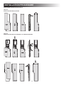
DOOR PANEL DIMENSIONS
RM2351, RM2354, RM2410, RM2451, RM2454, RM2510,
RM2620, DM2652, DM2662, DM2663, RM2551, RM2554,
RM3762, RM2820, DM2852, DM2862, RM3962 & NDM1062
PANEL DIMENSIONS
MAX. THICKNESS 5/32”
HEIGHT
MAX
WIDTH
MIN
MAX
MIN
UPPER DOOR
DM2652
DM2662
DM2663
DM2852
DM2862
NDM1062
15-27/32
15-25/32
20-3/4
20-5/8
RM2620
12-3/64
11-31/32
20-9/32
20-13/64
RM2820
14-7/8
14-51/64
22-11/64
22-3/32
RM3762
RM3962
17-3/64
16-31/32
23-25/32
23-11/16
LOWER DOOR / SINGLE DOOR
FIG 20 - RM2620 & RM2820, REVERSING THE DOOR SWING
- 20 -
RM2351
RM2354
26-17/64
26-3/16
19-5/8
19-17/32
RM2410
27-7/16
27-23/64
20-9/32
20-13/64
RM2510
35-5/16
35-15/64
20-9/32
20-13/64
RM2620
32-1/4
32-5/32
20-9/32
20-13/64
RM2820
RM2451
RM2454
DM2652
DM2662
DM2663
RM2551
RM2554
DM2852
DM2862
NDM1062
RM3762
35-5/16
35-15/64
22-11/64
22-3/32
32-9/16
32-1/2
20-3/4
20-5/8
38-11/16
38-5/8
20-3/4
20-5/8
32-7/16
32-23/64
23-25/32
23-11/16
RM3962
41-39/64
41-9/16
23-25/32
23-11/16
INSTALLATION PROCEDURE
DOOR PANEL DIMENSIONS CONT'D
NDA1402
RM1350
Freezer door
MODELS EQUIPPED
WITH ICE MAKER
PANEL DIMENSIONS
HEIGHT
WIDTH
MIN
MAX
MIN
.197(2x) (5)(2x)
+5
+ .197
.394 – .098 (10 –2.5)
FIG 21 - PANEL DIMENSIONS FOR THE FREEZER DOOR
MAX. THICKNESS 5/32"
MAX
Refrigerator doo
.197 (2x) (5)(2x)
UPPER DOOR
RM1350M
RM1350MIM
RM1350WIM
RM1350WID (left)
16
(42
19-7/32 19-9/64 15-43/64 15-19/32
11.181
(284)
9-13/64 15-43/64 15-19/32
59.842 (1520)
LOWER DOOR
RM1350M
RM1350MIM
40-1/32 39-31/32 15-43/64 15-19/32
RM1350WIM (right)
RM1350WID
45˚
27.224 (691.5)
(31.279 (794.5))
a
(32.106 (815.5))
RM1350WIM (left)
45˚
b
c
MAX 1.00
(MAX 25)
Freezer door
.295 (7.5)
15.237
(387)
MAX 1.00
(MAX 25)
Refrigerator door
.197(2x) (5)(2x)
+5
+ .197
.394 – .098 (10 –2.5)
f
d
+5
+ .197
.394 – .098 (10 –2.5)
FIG 22 - PANEL DIMENSIONS FOR THE FRIDGE DOOR
.197 (2x) (5)(2x)
16.811
(427)
9-49/64
min
max
9-11/16
d
11-55/64 11-49/64 28-17/64
max
e
min
15-43/64 15-19/32
max
40-1/32
min
45˚
45˚
min
28-3/16
f
MAX 1.00
(MAX 25)
39-31/32
12.756
(324)
15.237
(387)
min
MAX 1.00
(MAX 25)
- 21 -
.295 (7.5)
c
5-29/32
b
(32.106 (815.5))
max
max
28.051 (712.5)
5-63/64
min
27.224 (691.5)
(31.279 (794.5))
a
.295 (7.5)
max
59.842 (1520)
e
59.842 (1520)
11.181
(284)
28.051 (712.5)
RM1350WID (right) 9-9/32
INSTALLATION PROCEDURE
DOOR PANEL DIMENSIONS CONT'D
NDA1402
MODELS EQUIPPED WITH ICE DISPENSER / ICE & WATER DISFreezer door
PENSERS
Refrigerator door
Freezer door
Refrigerator door
Freezer door
Refrigerator door
MAX 1.00
(MAX 25)
11.181
(284)
11.181
11.181
(284) (284)
59.842 (1520)
.913 (23.2)
9.370 (238)
(32.106 (815.5))
59.842 (1520)
45˚
45˚
.295 (7.5)
28.051 (712.5)
(32.106 (815.5))
12.756
(324)
28.051 (712.5)
(32.106 (815.5))
28.051 (712.5)
27.224 (691.5)
27.224 (691.5)
MAX 1.00
(MAX 25)
12.756
(324)
.295 (7.5)
MAX 1.00
(MAX 25)
MAX 1.00
(MAX 25)
- 22 -
.295 (7.5)
12.756
(324)
15.237
(387)
.295 (7.5)
.295 (7.5)
15.237
(387)
MAX 1.00
(MAX 25)
59.842 (1520)
45
45
˚
45
15.237
(387)
27.224 (691.5)
+ .197
.394 – .098
29.921 (760)
+5
(10 –2.5)
+5
(10 –2.5)
+ .197
.394 – .098
29.921 (760)
MAX 1.00
(MAX 25)
45˚
˚
+ .197
.394 – .098
9.370 (238)
.197(2x) (5)(2x)
29.921 (760)
˚
+5
(10 –2.5)
9.370 (238)
.913 (23.2)
.295 (7.5)
.913 (23.2)
MAX 1.00
(MAX 25)
+ .197
.394 – .098
16.811
(427)
16.811
(427)
.197(2x) (5)(2x)
.197(2x) (5)(2x)
+5
(10 –2.5)
+5
(10 –2.5)
16.811
(427)
.295 (7.5)
14.960 (380)
.197 (2x) (5)(2x)
+ .197
.394 – .098
+5
(10 –2.5)
.197 (2x) (5)(2x)
.197 (2x) (5)(2x)
.295 (7.5)
MAX
1.00
MAX
1.00
(MAX
(MAX
25)25)
+ .197
.394 – .098
+ .197
.394 – .098
+5
(10 –2.5)
+ .197
.394 – .098
+ .197
.394 – .098
14.960 (380)
.197(2x) (5)(2x)
.295 (7.5)14.960 (380)
.197(2x) (5)(2x)
.197(2x) (5)(2x)
FIG 24 - PANEL DIMENSIONS FOR THE FRIDGE DOOR
+5
(10 –2.5)
+5
(10 –2.5)
FIG 23 - PANEL DIMENSIONS FOR THE FREEZER DOOR
INSTALLATION PROCEDURE
DOOR PANEL INSTALLATION CONT'D
RM2410, RM2510, RM2620 & RM2820
To install the door panel, follow these steps:
MOUNTING INSTRUCTIONS
1. Open the door 90 degrees.
2. Locate decoration strips. On some refrigerators, the
decoration strip is taped inside the door; if installed
on the door, remove the door decoration strip (2) by
removing its two screws (1).
3. Insert one vertical edges into the groove of the door
frame (3).
4. Bend the panel gently so that the free side of the
panel can be slipped into the corresponding groove
of the door frame (4). Slide the panel down into the
groove of the bottom frame (5).
5. Between the upper edge of the panel and the door
frame there is a gap which should be covered by the
decoration strip.
6. Put the decoration strip across the door so that the
gap is covered and push it upward (6). The tabs on
the inside of the strip should fit behind the flange of
the door frame.
7. Secure the decoration strip with the two screws
removed in step 1.
RM2351, RM2354, RM2451, RM2454, DM2652, DM2662,
DM2663, RM2551, RM2554, DM2852, DM2862 & NDM1062
To install the panel(s), follow these steps:
1. Open the door 90 degrees.
2. Locate decoration strips. These are taped to one of
the shelves or to the inside of the door. Loosen tape
and remove strips.
3. Insert the vertical edges into the grooves of the door
frame. Push the panel downwards so that the lower
horizontal edge of the panel is fitted into the bottom grove (FIG 25).
1
1
1
4. Fasten the decoration strips:
-- Screws: Secure decoration strip with three
2
screws (FIG 26).
-- Snap-in: Snap in the decoration strips (FIG 27).
FIG 25
FIG 26
1
1
1
FIG 28 - DOOR PANEL
1
3
3
2
1
2
1
FIG 27
4
2
5
4
3
5
6
1
- 23 -
1
INSTALLATION PROCEDURE
DOOR PANEL INSTALLATION CONT'D
5. Snap on the handle.
RM3762 & RM3962
To install the door panels, follow these steps:
1
2
1. Remove the decoration strip by inserting a finger in
the plastic profile and pull.
REPLACING THE DOOR PANELS
To replace a mounted door panel, follow these steps:
1. Detach the handle by using a flat blade screwdriver
to gently push the two tabs away.
2. Open the door 90 degrees.
3. Insert the door panel’s edges into the grooves of the
door frame. Push the panel sideways until the edge
of the panel is fitted into the opposite side groove.
2. Remove decoration strip and door panel.
3. Install the new panel according to the previous
instruction, steps 3-5.
4. Snap on the decoration strip.
- 24 -
INSTALLATION PROCEDURE
5. Put back the decoration strip. Slide (A) or
snap (B) into place.
DOOR PANEL INSTALLATION CONT'D
RM1350
To install the door panels, follow these steps:
1. Open the door.
2. Remove the screw (A). Slide off the handle (B).*
A
B
B
A
* For RM1350WID it is not necessary to
remove the right freezer door handle in
order to mount the door panel.
6. Slide the handle into place (A) and attach with
the screw (B).
3. Slide off the decoration strip.
A
B
4. Insert the door
panel’s edges into
the grooves of the
door frame.
Push the panel sideways until the edge
of the panel is fitted
into the opposite side
groove.
- 25 -
INSTALLATION PROCEDURE
DOOR PANEL INSTALLATION CONT'D
NDA1402
MODELS EQUIPPED WITH ICE MAKER
Freezer door
NDA1402
Freezer door
MODELS EQUIPPED WITH ICE DISPENSER / ICE & WATER DISPENSERS
Refrigerator door
Refrigerator door
- 26 -
INSTALLATION PROCEDURE
INSTALLING THE DOOR HANDLES
NDM1062
To install the door handles, follow these steps:
RM3762 & RM3962 - Stainless steel doors
To install the door handles, follow these steps:
1. Locate the plastic bag containing the handles and
screws.
2. Open freezer door.
3. Position handle. Align the holes in the
handle with the holes in the frame.
1. Snap on the handle by inserting its two tabs in the
slot and slide into place.
Door insert panels Stainless steel doors
2. Attach the handle with two screws.
4. While holding handle firmly against the door, fasten
screws with a Phillips screwdriver. Close the door.
5. Open fridge door and repeat steps 3 and 4 to install
the second handle.
REFRIGERATOR REMOVAL
Door insert panels Stainless steel doors
Before removing the refrigerator:
1. Verify that the 120 VAC power cord is disconnected at the rear of the refrigerator.
2. Verify that the 12 VDC leads are disconnected
and capped at the rear of the refrigerator.
3. Shut off the gas supply.
4. Disconnect and cap the LP gas line at rear of
refrigerator.
To replace the refrigerator:
1. Make sure the sealing strips (isolating the appliance combustion system from the vehicle
interior) are properly positioned for a complete
seal.
2. Slide the refrigerator back into the compartment.
3. Replace the screws anchoring the refrigerator
to the enclosure.
4. Reconnect the LP gas supply line at the rear of
the refrigerator.
Always use a backup wrench when loosing
and tightening LP gas connections.
Always use a backup wrench when loosing
and tightening LP gas connections.
Refrigerator removal and installation should be
performed by a qualified service technician.
To remove the refrigerator:
1. Remove the screws anchoring the refrigerator
to the enclosure.
2. Slide the refrigerator out of the compartment.
- 27 -
5. Check all connections for LP gas leaks.
6. Reconnect the 12 VDC leads at rear of refrigerator.
7. Reconnect the 120 VAC power cord at rear of
refrigerator.
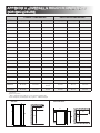
APPENDIX A - OVERALL & ROUGH IN DIMENSIONS
FOR ENCLOSURE
OVERALL DIMENSIONS
MODEL
Height (A)
Width (B)
ENCLOSURE DIMENSIONS
Depth (C)
Height (H)
Width (W)
Depth (D)
RM2351
30-5/32
21-7/8
22-22/32
29-3/4
20-1/2
21-1/2
RM2354
30-5/32
21-7/8
22-22/32
29-3/4
20-1/2
21-1/2
RM2410
33-1/2
22-53/64
24-7/8
32-7/16
21-13/16
24-7/32
RM2451
37-3/8
24-7/8
24-11/16
36-1/2
23-11/16
24
RM2454
37-3/8
24-7/8
24-11/16
36-1/2
23-11/16
24
RM2510
40-29/32
22-53/64
24-7/8
40-5/16
21-13/16
24-7/32
RM2551
43-1/2
24-7/8
24-11/16
42-5/8
23-11/16
24
RM2554
43-1/2
24-7/8
24-11/16
42-5/8
23-11/16
24
RM2620
51-31/32
22-23/32
24-9/16
49-17/32
21-13/16
24-7/32
DM2652
54-21/32
24-7/8
26-1/32
53-3/4
23-11/16
243
DM2662
54-21/32
24-7/8
26-1/32
53-3/4
23-11/16
243
DM2663
54-21/32
24-7/8
26-1/32
53-3/4
23-11/16
243
RM3762
54-3/4
25-5/64
26-1/16
53-3/4
23-11/16
243
RM2820
57-7/8
24-39/64
24-9/16
55-7/16
23-11/16
243
DM2852
60-51/64
24-7/8
26-1/32
59-15/16
23-11/16
243
DM2862
60-51/64
24-7/8
26-1/32
59-15/16
23-11/16
243
RM3962
63-15/16
25-5/64
26-1/16
62-61/64
23-11/16
243
NDM1062
60-54/64
24-7/8
26-5/8
59-15/16
23-11/16
243
RM1350
64-17/64
33-11/16
28-1/161 ,
29-1/22
63-3/16
32-3/4
26-1/164
NDA1402
64-17/64
33-11/16
29-5/8
63-3/16
32-3/4
26-1/164
1
Steel doors
Door insert panels
3
Add 1” depth for units with one or two optional ventilator fans.
4
Units with factory installed fans may require 1” additional depth.
2
SIDE VIEW
VIEW FROM ABOVE
C
C
D
D
A
A
H
- 28 -
B
W
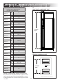
APPENDIX B - MINIMUM VENTILATION HEIGHTS
B1
ROOF VENT & LOWER SIDE VENT
MINIMUM VENTILATION HEIGHTS
B1 = ROOF VENT & LOWER SIDE VENT
B2 = UPPER & LOWER SIDE VENT
RM2351
RM2354
RM2410
RM2451
RM2454
RM2510
RM2551
RM2554
RM2620
DM2652
DM2662
DM2663
RM3762
RM2820
DM2852
DM2862
RM3962
NDM1062
B1
B2
31
34
B1
31
B2
34
B1
34
B2
38
B1
37-3/4
B2
36
B1
37-3/4
B2
36
B1
42
B2
38
B1
44-1/2
B2
42
B1
44-1/2
B2
42
B1
57-3/4
B2
49
B1
57-3/4
B2
56
B1
57-3/4
B2
56
B1
57-3/4
B2
56
B1
57-3/4
B2
56
B1
63-3/4
B2
57
B1
63-3/4
B2
61
B1
63-3/4
B2
61
B1
66-13/16
B2
63
B1
63-3/4
B2
61
RM1350
NDA1402
Minimum
Ventilation
Height
B2
UPPER & LOWER SIDE VENT
Minimum
Ventilation
Height
63
B1
B2
Fan(s)*
69-1/8
63
NOTE! Ventilation height should be measured from
the seam between the frame and door of the lower side
wall vent to the top of the roof opening (B1) or to top
of the uppermost row of louvers on the upper side wall
vent (B2).
* Fan(s) position may vary by model.
- 29 -
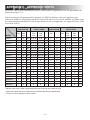
APPENDIX C - APPROVED VENTS
Refer to the table below for information on which vents and fans (if applicable) to use. The part numbers are
displayed on pages 31-33.
Start by locating the refrigerator model in question, e.g. RM2351 and then, select vent application type.
In this case, numbers 1 and 2 indicate that Roof Vent (1) and Side Vent (2) could be installed. As another example, when selecting model DM2652 with an upper and lower side vent application, use Upper Side Vent (2) and
Lower Side Vent (2).
INST. TYPE
MODEL
ROOF VENT
APPLICATION
Roof Lower
Vent Side
Vent
UPPER & LOWER SIDE
APPLICATION
ISLAND
APPLICATION
CORNER
APPLICATION
Fan
Upper
Side
Vent
Lower
Side
Vent
Fan
Roof
Vent
Fan
Roof
Vent
Upper
Side
Vent
Lower
Side
Vent
Fan
RM2351
1
2
8**
7, 3*, 4*
7, 5*
8**
1
8
1
7, 4**
7, 5*
8
RM2354
1
2
8**
7, 3*, 4*
7, 5*
8**
1
8
1
7, 4**
7, 5*
8
RM2410
1
2
8**
2, 7*, 4*
2, 7*, 5*
8**
1
8
1
2, 7*, 4* 2, 7*, 5*
8
RM2451
1
2
8**
2, 7*, 4*
2, 7*, 5*
8**
1
8
1
2, 7*, 4* 2, 7*, 5*
8
RM2454
1
2
8**
2, 7*, 4*
2, 7*, 5*
8**
1
8
1
2, 7*, 4* 2, 7*, 5*
8
RM2510
1
2
8**
2, 7*, 4*
2, 7*, 5*
8**
1
8
1
2, 7*, 4* 2, 7*, 5*
8
RM2551
1
2
8**
2, 7*, 4*
2, 7*, 5*
8**
1
8
1
2, 7*, 4* 2, 7*, 5*
8
RM2554
1
2
8**
2, 7*, 4*
2, 7*, 5*
8**
1
8
1
2, 7*, 4* 2, 7*, 5*
8
RM2620
1
2
9**
2
2
9
1
9
1
2
2
9
DM2652
1
2
9**
2
2
9
1
9
1
2
2
9
DM2662
1
2
9**
2
2
9
1
9
1
2
2
9
DM2663
1
2
9**
2
2
9
1
9
1
2
2
9
RM3762
1
2
9**
2
2
9
1
9
1
2
2
9
RM2820
1
2
9**
2
2
9
1
9
1
2
2
9
DM2852
1
2
9**
2
2
9
1
9
1
2
2
9
DM2862
1
2
9**
2
2
9
1
9
1
2
2
9
RM3962
1
2
9**
2
2
9
1
9
1
2
2
9
NDM1062
1
2
9**
2
2
9
1
9
1
2
2
9
RM1350
1
6
***
6
6
***
1
***
1
6
6
***
NDA1402
1
6
***
6
6
***
1
***
1
6
6
***
*Optional vents may be used in applications where the preferred vent cannot be used.
**Optional fan. Note that some models can be purchased with factory installed fan(s).
***Fan(s) are factory installed on these models.
- 30 -
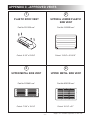
APPENDIX C - APPROVED VENTS
1
2
PLASTIC ROOF VENT
UPPER & LOWER PLASTIC
SIDE VENT
Part No 3311236.xxx*
Part No 3109350.xxx*
Cutout: 6-1/2” x 23-3/4”
Cutout: 13-3/4” x 21-9/16”
3
4
UPPER METAL SIDE VENT
UPPER METAL SIDE VENT
Part No 3100451.xxx*
Part No 8030122.xxx*
Cutout: 7-3/4” x 19-1/4”
Cutout: 10-1/4” x 21”
- 31 -
*Suffix “xxx” should be replaced by a color code
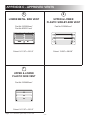
APPENDIX C - APPROVED VENTS
5
6
LOWER METAL SIDE VENT
UPPER & LOWER
PLASTIC SIDE-BY-SIDE VENT
Part No 3102364.xxx*
Part No 8030211.xxx*
Part No 3109349.xxx*
Cutout: 9-11/16” x 19-1/4”
Cutout: 13-5/8” x 28-5/8”
7
UPPER & LOWER
PLASTIC SIDE VENT
Part No 3109492.xxx*
Cutout: 9-11/16” x 19-1/4”
*Suffix “xxx” should be replaced by a color code
- 32 -
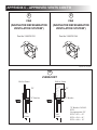
APPENDIX C - APPROVED VENTS CONT'D
8
9
FAN
FAN
(INNOVATOR REFRIGERATOR
VENTILATION SYSTEM*)
(INNOVATOR REFRIGERATOR
VENTILATION SYSTEM*)
Part No 3108705.751
Part No 3108705.744
*
Patent #5,355,693
10
Z-BRACKET
Wall or Frame
Wall or Frame
"D"
"D"
"Z" Bracket
"Z" Bracket
Vent
Frame
Vent
Frame
- 33 -
"Z" Bracket 3103812.
XXX
Use appropriate "D"
XXX = 016 = .62"
XXX = 024 = .81"
XXX = 040 = .19"
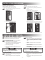
APPENDIX D - VENT INSTALLATION PROCEDURES
Reference “APPENDIX C” for Approved Vents.
All fasteners referenced herein are to be provided by the installer. The screw types selected should be appropriate for
the application for which they are being used. For example; wood screw thread type for wood engagement, self tapping screw thread type for metal engagement, and plastic screw thread type for plastic engagement. Unless otherwise
noted, minimize lengths to fit applications appropriately. Rivets are acceptable for use only where noted.
•APPLY SEALANT AROUND THE THREAD OR RIVET BODY OF ALL FASTENERS.
•APPLY DRY SEALANT AROUND SURFACE MOUNTING FACE OF ALL VENT FRAMES OR VENT
BASES PRIOR TO INSTALLATION.
•APPLY WET SEALANT AROUND PERIMETER OF ALL VENT FRAMES OR VENT BASES AFTER
INSTALLATION. ENSURE THAT SEALANT DOES NOT BLOCK THE MOLDED WEEP TRACKS IN
THE VENT FRAME.
1
ROOF VENT (CAP & BASE) PART # 3311236.XXX
5
a)Place vent over 9 11/16”x 19 ¼” cutout.
b)Secure frame using sixteen #10 screws.
- Alternate use of rivets is acceptable.
a) Center the base over the 6 ½” x 23 ¾” cutout.
b)Secure using ten #10 screws.
c) Place cap on top of base.
d)Secure cap to base using four #10 screws.
These screws must be a minimum of 1 ¼”
long to provide proper engagement.
e) Apply sealant over all the screws.
2
6
UPPER & LOWER SIDE VENT PART # 3109350.XXX
7
UPPER METAL SIDE VENT PART # 3100451.XXX
UPPER & LOWER PLASTIC SIDE VENT PART # 3109492.XXX
a)Place frame into 9 11/16” x 19 ¼” cutout.
b)Secure the frame with seven Z-brackets
(see APPENDIX C”) using #10 screws.
c)Install the vent door into frame using
upper tabs as a guide.
d)Lock the vent door into place by fully
seating and twisting the black latches in
the bottom corners of the vent door.
a)Place vent over 7 ¾“ x 19 ¼” cutout.
b)Secure frame using fourteen #10 screws.
- Alternate use of rivets is acceptable.
4
UPPER & LOWER PLASTIC SIDE-BY-SIDE
VENT - PART # 3109349.XXX
a)Place frame into 13 5/8” x 28 5/8” cutout.
b)Secure the frame with five Z-brackets (see
“APPENDIX C”) using #10 screws.
c)Install six #10 screws through the front
frame (three each end) to further secure
frame.
d)Remove screw cap plugs from the vent
frame and install over the six screws in
the front frame.
e)Install the vent door into frame using
upper tabs as a guide.
f) Lock the vent door into place by fully
seating and twisting the black latches in
the bottom corners of the vent door.
a) Place frame into 13 ¾” x 21 9/16” cutout.
b)Secure frame using ten #10 screws through
inside flange of frame.
- Alternatively, use seven Z-brackets (see
“APPENDIX C”) if the cutout is not framed
or the wall is laminate construction. Use #10
screws to secure the frame via the Z-brackets.
c) Install the vent door into the frame using the
upper tabs as a guide.
d)Lock the vent door into place by fully seating
and twisting the black latches in the bottom
corners of the vent door.
3
LOWER METAL SIDE VENT PART # 3102364.XXX / PART # 8030211.XXX
UPPER METAL SIDE VENT PART # 8030122.XXX
a)Place vent over 10 ¼” x 21” cutout.
b)Secure frame using sixteen #10 screws.
- Alternate use of rivets is acceptable.
- 34 -
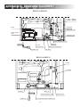
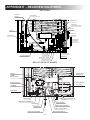
APPENDIX E - REARVIEW EQUIPMENT
RM2351 & RM2354
1 heater - RM2351
2 heaters - RM2354
Relay
Flue baffle
Drain water hose
Power module
cover
Protection cover
Screw for protection cover
12 V DC
Terminal block
Burner jet
Manual gas shutoff valve
Inlet fitting
Flexible cord
RM2410 & RM2510
Heater
Flue baffle
Inlet fitting
Burner jet
Screw for protection cover
Flexible cord
12 volt DC terminal block - RM2510 only
- 35 -
Protection cover
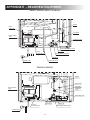
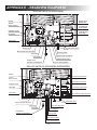
APPENDIX E - REARVIEW EQUIPMENT
RM2451, RM2454, RM2551 & RM2554
Heater
Relay,
3-way only
Flue baffle
Power module
cover
Protection cover
12V DC
Screw for protection cover
Burner jet
12 volt
Terminal block
Manual gas shutoff valve
Inlet fitting
Flexible cord
Drain water hose
RM2620 & RM2820
Heater
Thermofuse
Flue baffle
Power module
cover
Protection
cover
Drain water hose
12V DC
12 volt
terminal block
Inlet fitting
Burner jet
Manual gas shutoff valve
Flexible cord
- 36 -
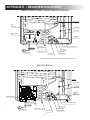
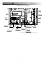
APPENDIX E - REARVIEW EQUIPMENT
DM2652, DM2662, DM2663, DM2852, DM2862 & NDM1062
Heater(s)
Relay,
3-Way only
Thermofuse
Flue baffle
Power module
cover
Protection
cover
12V DC
Screw for protection cover
12 volt DC
Terminal block
Burner jet
Drain water hose
Flexible cord
Inlet fitting
Manual gas
shutoff valve
Shown without Secondary Burner Housing for illustrative purposes only.
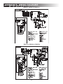
RM3762 & RM3962
Heater
Thermofuse
Flue baffle
385 13 31−01
HVT
J3
J2
F3 (5A)
Power module
J1
SWITCHED
12V
LAMP
F4 (5A)
TEST
LINE
AC HTR AC HTR
NEUT
LINE
Protection
cover
NEUT
5
12V DC
12 volt
Terminal block
Screw for protection cover
D+
Burner jet
Flexible cord
Drain water hose
Inlet fitting
- 37 -
Manual gas
shutoff valve
APPENDIX E - REARVIEW EQUIPMENT
RM1350M
Heaters
Drain Water Hose
Protection Plate
385 13 31−01
HVT
J2
F3 (5A)
J3
J1
SWITCHED
12V
LAMP
F4 (5A)
TEST
LINE
AC HTR AC HTR
NEUT
LINE
NEUT
12V DC
D
Flexible Cord
Power Module
Terminal Block, 12V DC
LP - Gas Connection
RM1350IM, RM1350MIM & RM1350WIM
Water Hose
Icemaker
Heating Cable
Drain Water Hose
Water Hose
Water in the Door
(RM1350WIM Only)
Heaters
Flexible Cord
Icemaker
Protection Plate
Flexible Cord
Refrigerator
385 13 31−01
HVT
J2
F3 (5A)
J3
J1
SWITCHED
12V
LAMP
F4 (5A)
TEST
LINE
AC HTR AC HTR
NEUT
LINE
NEUT
12V DC
D
LP - Gas Connection
Water Valve
Terminal Block, 12V DC
Alternator Signal Wire *
Thermostat
*
Heating Cable
(RM1350WIM Only)
Power Module
*Valid for refrigerators equipped with the automatic door locking system.
- 38 -
APPENDIX E - REARVIEW EQUIPMENT
RM1350WID
Water Hose
Icemaker
Heating Cable
Drain Water Hose
Water Hose
Water Dispenser Door
Control Unit
Heaters
Protection Plate
Flexible Cord
Ice Dispenser
WARNING !
PART No. 385 13 78−01
DISCONNECT 120 V AC
BEFORE SERVICING
J5
J4
5A
CHECK FUSE
BEHIND COVER
J6
J3
J2
J1
Flexible Cord
Refrigerator
385 13 31−01
HVT
J3
J2
F3 (5A)
12V DC
J1
SWITCHED
12V
LAMP
F4 (5A)
TEST
LINE
AC HTR AC HTR
NEUT
LINE
NEUT
5
D
Water Valve
LP - Gas Connection
Heating Cable
Thermostat
Power Module
Terminal Block, 12V DC
Alternator Signal Wire
NDA1402 (WITH ICE MAKER)
Heaters
Flexible Cord
Refrigerator
12V DC
Burner Control
Protection Cover
Power Module
and Fuses
Flue Baffle
12V DC
12V DC
Thermofuse
Burner Jet
Drain Water Hose
Manual Gas Shut Off Valve
Heating Cable
Inlet Fitting
Water Hose (Icemaker)
Thermostat
Water Solenoid Valve
12 V DC Terminal Block
Flexible Cord Icemaker
- 39 -
APPENDIX E - REARVIEW EQUIPMENT
NDA1402 (WITH ICE DISPENSER)
Heaters
Flexible Cord
Refrigerator
12V DC
Burner Control
Ice Dispenser
Power Switch
Protection Cover
Power Module
and Fuses
Flue Baffle
12V DC
12V DC
Thermofuse
Burner Jet
Drain Water Hose
Manual Gas Shut Off Valve
Heating Cable
Inlet Fitting
Water Hose (Icemaker)
Thermostat
Water Solenoid Valve
Flexible Cord
Icemaker, Ice Dispenser
12 V DC Terminal Block
NDA1402 (WITH ICE AND WATER DISPENSERS)
Heaters
Flexible Cord Refrigerator
12V DC
Burner Control
Dispenser Power Switch
Protection Cover
Flue Baffle
Power Module and Fuses
12V DC
12V DC
Thermofuse
90° Connection, Water Dispenser
Burner Jet
Drain Water Hose
Manual Gas Shut Off Valve
Inlet Fitting
Thermostat
Flexible Cord
Icemaker, Ice Dispenser
Hose, Water Dispenser
Hose, Icemaker
Heating Cable
Water Solenoid Valve
12 V DC Terminal Block
- 40 -
APPENDIX E - REARVIEW EQUIPMENT
NDM1062 (WITH ICE MAKER)
Heater
Relay
Thermofuse
Power
Module
Cover
Flue Baffle
Protection
Cover
12V DC
Flexible Cord
12V DC
Terminal Block
Manual Gas
Shutoff Valve
Flexible Cord
(Icemaker)
Thermostat
Burner Jet
Inlet Fitting
Drain Water Hose
Shown without Secondary Burner Housing for illustrative purposes only.
- 41 -
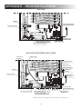
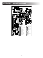
APPENDIX F - WIRING DIAGRAMS
RM2351, RM2451 & RM2551
RM2354, RM2454 & RM2554
- 42 -
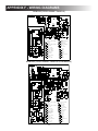
APPENDIX F - WIRING DIAGRAMS
RM2410
385 13 76
120 VOLTS AC
N
L
5a
4L
4a
3
3a
2
2a
1
1a
D
C
D
A
120 VOLTS AC
B
1
A
1
3
N
L
5N
1
5N
5a
2
4L
4a
SWITCH
A
3
3a
2
2a
1
1a
B THERMOSTAT
JUNCTION BLOCK
C
D HEATER
2
WHITE
1
2
C
B
3
BLACK
GREEN
RM2510
293 00 92 2
12 VOLTS DC
N
L
E
12 VOLTS DC
F
D
C
D
2
100/120 VOLTS AC
1
A
3
N
L
100/120 VOLTS AC
G
B
A
A
1
1
5
2
A
F
2
1
5
1
2
6
G
2
4
B
3
5
C
- 43 -
WHITE
2 BLACK
GREEN
4 GREEN/YELLOW
RED
6 GREY
C
E
G
SWITCH
B THERMOSTAT
JUNCTION BLOCK
D HEATER
TERMINAL BLOCK
F REIGNITER
PILOT LAMP
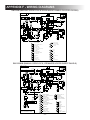
APPENDIX F - WIRING DIAGRAMS
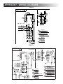
RM2620 & RM2820
385 14 81
T
GREEN
ORANGE
BLUE
RED
BROWN
BLACK
9
A
P2−1
P2−2
E
J8
J5
J4
J2
GROUND
L
N
9
8
C
B
+12V
4
J10
9
P3−4
P3−3
P3−2
P3−1
J7
M
P1−1
P1−4
P1−2
P1−5
P1−6
P1−3
J6
D
N
3A
J4
J6
J5
3
3
J7
5A
J2
1
H
P2
1234
123456
12
3
G
J
J10
P1
J
1
1
J8
P3
1
1
K
F
9
1
P
5
S
L
6
T
L
M
DISPLAY
BOARD
O
N
12V DC
E
A
CIRCUIT BOARD POWER
FUSE 3A
FUSE 5A
CIRCUIT BOARD DISPLAY
ELECTRODE
THERMOFUSE
LAMP
SWITCH LAMP
HEATER 120V AC
HEATING CABLE
TERMINAL BLOCK
THERMISTOR
SOLENOID VALVE
RETAINER
B
C
D
N
E
F
G
H
F
J
H
K
G
L
M
N
K
O
PROTECTIVE EARTH
CHASSIS GROUND
TEST POINT
P
S
T
1
BLACK
BROWN
RED
YELLOW
GREEN
GREEN/YELLOW
BLUE
GREY
WHITE
2
3
4
5
6
7
8
9
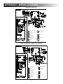
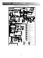
DM2652, DM2662, DM2852 & DM2862
385 14 82
T
GREEN
ORANGE
BLUE
RED
BROWN
BLACK
9
A
P2−1
P2−2
J10
J5
J4
GROUND
L
N
9
E
J2
+12V
4
8
C
B
J8
9
P3−4
P3−3
P3−2
P3−1
J7
M
P1−1
P1−4
P1−2
P1−5
P1−6
P1−3
J6
D
N
J4
3A
J6
J5
J2
3
J7
5A
3
1
J8
3
H
P1
P2
1234
123456
12
G
J
U
K
F
1
9
1
P
5
L
T
DISPLAY
BOARD
L
M
P
B
C
D
E
F
G
H
F
H
J
G
K
L
M
N
K
6
12V DC
A
U
S
N
E
N
J
1
1
J10
P3
1
O
CIRCUIT BOARD POWER
FUSE 3A
FUSE 5A
CIRCUIT BOARD DISPLAY
ELECTRODE
THERMOFUSE
LAMP
SWITCH LAMP
HEATER 120V AC
HEATING CABLE
TERMINAL BLOCK
THERMISTOR
SOLENOID VALVE
RETAINER
- 44 -
S
T
U
1
2
3
4
5
6
7
8
9
PROTECTIVE EARTH
CHASSIS GROUND
TEST POINT
THERMAL FUSE
BLACK
BROWN
RED
YELLOW
GREEN
GREEN/YELLOW
BLUE
GREY
WHITE
O
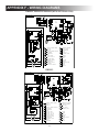
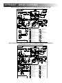
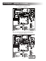
APPENDIX F - WIRING DIAGRAMS
DM2652, DM2852 & DM2862 (WITH OPTIONAL FAN)
385 14 84
T
GREEN
ORANGE
BLUE
RED
BROWN
BLACK
9
P2−1
P2−2
J6
J5
J4
GROUND
L
N
9
E
J2
+12V
4
8
C
B
J8
9
P3−4
P3−3
P3−2
P3−1
A
J10
M
P1−1
P1−4
P1−2
P1−5
P1−6
P1−3
J7
D
U
V
N
3
3A
J4
J6
J5
X
3
3
J7
5A
J2
3
J8
1
1
1
1
1
J
J10
P3
P1
P2
1234
123456
12
H
Y
F
9
1
K
1
P
5
S
L
6
T
L
M
DISPLAY
BOARD
A
CIRCUIT BOARD POWER
FUSE 3A
FUSE 5A
CIRCUIT BOARD DISPLAY
ELECTRODE
THERMOFUSE
LAMP
SWITCH LAMP
HEATER 120V AC
HEATING CABLE
TERMINAL BLOCK
THERMISTOR
SOLENOID VALVE
RETAINER
PROTECTIVE EARTH
B
C
D
E
N
F
G
H
F
J
K
V
U
L
M
3A
H
O
N
12V DC
E
Y
J
3
G
N
G
O
P
S
T
U
V
X
Y
1
2
3
4
5
6
7
8
9
K
CHASSIS GROUND
TEST POINT
THERMOFUSE
FAN
FUSE 3A
THERMAL FUSE
BLACK
BROWN
RED
YELLOW
GREEN
GREEN/YELLOW
BLUE
GREY
WHITE
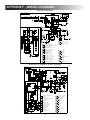
DM2663
385 14 83
9
A
P2−1
P2−2
J2
7
O
9
J10
J8
J7
J5
J2
3
3
J7
5A
4
W
J6
J5
30
E
N
3A
86
8
C
B
GROUND
J4
7
P3−4
P3−3
P3−2
P3−1
J6
9
P1−1
P1−4
P1−2
P1−5
P1−6
P1−3
J4
N
L
87
P
GREEN
ORANGE
BLUE
RED
BROWN
BLACK
+12V
85
X
D
1
1
3
J8
3
1
3
1
K
J10
P3
P1
P2
1234
123456
12
G
L
X
1
3
H
Y
F
1
9
1
S
5
M
L
U
6
N
DISPLAY
BOARD
J
K
R
N
12V DC
E
Y
85
87
86
30
F
J
A
B
C
D
P
W
E
F
G
H
J
O
K
H
G
L
M
N
O
L
P
R
CIRCUIT BOARD POWER
FUSE 3A
FUSE 5A
CIRCUIT BOARD DISPLAY
ELECTRODE
THERMOFUSE
LAMP
SWITCH LAMP
HEATER 12V DC
HEATER 120V AC
HEATING CABLE
TERMINAL BLOCK
THERMISTOR
SOLENOID VALVE
RELAY
RETAINER
- 45 -
S
U
W
X
Y
1
2
3
4
5
6
7
8
9
PROTECTIVE EARTH
CHASSIS GROUND
FUSE 30A
TEST POINT
THERMAL FUSE
BLACK
BROWN
RED
YELLOW
GREEN
GREEN/YELLOW
BLUE
GREY
WHITE
APPENDIX F - WIRING DIAGRAMS
RM3762 & RM3962
385 14 95 1
N
CIRCUIT BOARD POWER
A
BROWN
BLACK
RED
B
G
P1−1
P1−2
P1−3
C
9
H
9
9
3
P2−1
P2−2
J
4
7
E
J3
F
P2
P4
P3
P1
P7
P5
D
J1
P6
J2
7
F3
F
P2
1
10
GROUND
N L
3
1
P4
1
E
P3
P1
9
10
1
9
1
6
5
M
S
J2
D
F3
R
8
12V DC
L
D+
H
DISPLAY
C
BUTTONS
D
J
E
F
T
G
G
H
J
K
L
S
M
N
O
P
SWITCH LAMP
LAMP
HEATING CABLE
S
T
CONTROL BOARD
CIRCUIT BOARD DISPLAY
THERMISTOR
FUSE 5A MINI AUTO
FUSE 5A GLASS
SOLENOID VALVE
ELECTRODE
THERMAL FUSE
THERMO FUSE
HEATER 120V AC
PROTECTIVE EARTH
RETAINER
BURNER HOUSING
CHASSIS GROUND
TERMINAL BLOCK
B
N
R
1
A
C
O
P
+
J1
J3
T
P6
P5
K
L
3
P7
1
K
1
BLACK
BROWN
RED
YELLOW
GREEN
GREEN/YELLOW
BLUE
GREY
WHITE
LIGHT BLUE
2
3
4
5
6
7
8
9
10
NDM1062 (STAINLESS STEEL DOORS)
385 14 04
D
T
GREEN
ORANGE
BLUE
RED
BROWN
BLACK
1
8
J4
J10
C
B
M
N
3
3
+12V
GROUND
L
N
J4
3A
J2
V
3
J6
J5
H
Y
J10
P1
P2
1234
123456
12
U
H
1
8
F
G
L
9
5
S
6
P
12V DC
A
+12V
LAC
GND
CLC
B
C
D
F
M
G
H
E
J
K
J
N
L
M
N
G
F
U
R
K
L
E
Y
1
N
T
DISPLAY
BOARD
3A
1
1
3
J8
P3
3
1
1
1
1
J7
5A
O
9
E
1
J5
8
3
4
P2−1
P2−2
J2
3
9
J8
9
P3−4
P3−3
P3−2
P3−1
A
J7
L
P1−1
P1−4
P1−2
P1−5
P1−6
P1−3
J6
+12V
LAC
GND
CLC
J
O
P
CIRCUIT BOARD POWER
FUSE 3A
FUSE 5A
CIRCUIT BOARD DISPLAY
ELECTRODE
LAMP
SWITCH LAMP
HEATER 120V AC
HEATING CABLE
TERMINAL BLOCK
THERMISTOR
THERMOFUSE
FANS
SOLENOID VALVE
RETAINER
O
- 46 -
R
S
T
U
V
Y
1
2
3
4
5
6
7
8
9
PROTECTIVE EARTH
CHASSIS GROUND
TEST POINT
THERMOFUSE
FUSE 3A
THERMAL FUSE
BLACK
BROWN
RED
YELLOW
GREEN
GREEN/YELLOW
BLUE
GREY
WHITE
APPENDIX F - WIRING DIAGRAMS
NDM1062 (STAINLESS STEEL DOORS & ICE MAKER)
385 14 44
D
T
GREEN
ORANGE
BLUE
RED
BROWN
BLACK
1
E
J10
J4
M
N
3
3
+12V
GROUND
L
3
N
J4
3A
J2
V
3
1
H
3
J8
Y
F
P3
P1
P2
1234
123456
12
L
87
+12V
LAC
GND
CLC
AD
C
G
F
D
E
O
F
Y
G
H
86
J
85
K
87
30
AD
L
AA
M
3A
N
O
AE
M
B4
L N
P
R
S
AB
C°
T
GROUND
9
U
6
M
5
B4
AA
AB
9
C
AF
B
6
6
AC
E
U
9
1
1
A
P
12V DC
AG
°
N
6
2
AE
J
N
1
M
S
K
5
3
30
3
1
9
86
85
L
R
1
G
T
DISPLAY
BOARD
1
U
8
H
1
AF
1
J7
5A
J10
AG
3
1
1
1
1
J6
J5
O
9
8
C
B
J5
3
4
P2−1
P2−2
J2
3
8
9
1
J8
9
P3−4
P3−3
P3−2
P3−1
A
J7
L
P1−1
P1−4
P1−2
P1−5
P1−6
P1−3
J6
+12V
LAC
GND
CLC
J
L
N
120 V AC
CIRCUIT BOARD POWER
FUSE 3A
FUSE 5A
CIRCUIT BOARD DISPLAY
ELECTRODE
LAMP
SWITCH LAMP
HEATER 120V AC
HEATING CABLE
TERMINAL BLOCK
THERMISTOR
THERMOFUSE
FANS
SOLENOID VALVE
RETAINER
PROTECTIVE EARTH
CHASSIS GROUND
TEST POINT
THERMOFUSE
- 47 -
V
Y
AA
AB
AC
AD
AE
AF
AG
1
2
3
4
5
6
7
8
9
PROTECTIVE EARTH
CHASSIS GROUND
ICEMAKER
WATER VALVE
TERMINAL BLOCK
RELAY
HEATING CABLE
THERMOSTAT
FUSE 4A
BLACK
BROWN
RED
YELLOW
GREEN
GREEN/YELLOW
BLUE
GREY
WHITE
APPENDIX F - WIRING DIAGRAMS
NDM1062 (DOOR INSERT PANELS)
385 14 05
Z
GREEN
ORANGE
BLUE
RED
BROWN
BLACK
9
E
J8
J5
J4
J2
J
8
C
M
GROUND
L
N
3A
J4
T
3
3
1
1
J7
5A
J2
J8
1
R
P1
P2
123456
12
W
U
G
L
F
6
P
N
S
C
D
E
F
F
M
G
H
U
J
K
L
J
M
N
T
N
O
P
W
R
O
PROTECTIVE EARTH
SWITCH
SWITCH L.A.C
THERMOFUSE
CHASSIS GROUND
FUSE 3A
TEST POINT
T
CIRCUIT BOARD POWER
FUSE 3A
FUSE 5A
CIRCUIT BOARD DISPLAY
ELECTRODE
LAMP
SWITCH LAMP
HEATER 120V AC
HEATING CABLE
TERMINAL BLOCK
THERMISTOR
THERMOFUSE
FANS
SOLENOID VALVE
RETAINER
THERMAL FUSE
B
E
R
X
K
12V DC
A
G
S
5
L
DISPLAY
BOARD
1
8
Z
3A
9
1
1
H
3
H
J10
P3
3
1
1
1
1
3
3
8
1234
N
3
3
Y
J6
J5
O
9
P2−1
P2−2
B
+12V
4
J10
9
P3−4
P3−3
P3−2
P3−1
A
J7
L
P1−1
P1−4
P1−2
P1−5
P1−6
P1−3
J6
D
U
W
X
Y
Z
1
BLACK
BROWN
RED
YELLOW
GREEN
GREEN/YELLOW
BLUE
GREY
WHITE
2
3
4
5
6
7
8
9
NDM1062 (DOOR INSERT PANELS & ICE MAKER)
385 14 52
D
Z
GREEN
ORANGE
BLUE
RED
BROWN
BLACK
1
L
9
9
E
8
C
J5
J2
J4
8
U
M
N
3
GROUND
L
3
Y
3
N
3A
J4
1
5A
R
F
J10
P3
P1
P2
123456
12
H
1
L
DISPLAY
BOARD
L
85
86
87
30
AD
B
N
J
C
D
E
R
F
G
O
H
J
86
85
30
87
K
L
M
AA
N
3A
O
P
AE
M
AF
B4
L N
R
S
T
AB
C°
9
1
2
U
GROUND
W
6
9
6
6
M
5
B4
AA
AB
9
C
AF
A
P
12V DC
1
°
U
6
AC
M
T
N
1
F
X
K
5
3
AE
1
9
AG
3
E
G
1
S
1
G
Z
AD
1
W
8
AG
1
H
J8
1234
1
1
3
J7
W
3
1
J6
J5
J2
3
3
+12V
O
9
P2−1
P2−2
B
3
4
J10
3
P3−4
P3−3
P3−2
P3−1
A
J8
1
P1−1
P1−4
P1−2
P1−5
P1−6
P1−3
J7
T
J6
J
L
N
120 V AC
CIRCUIT BOARD POWER
FUSE 3A
FUSE 5A
CIRCUIT BOARD DISPLAY
ELECTRODE
LAMP
SWITCH LAMP
HEATER 120V AC
HEATING CABLE
TERMINAL BLOCK
THERMISTOR
THERMOFUSE
FANS
SOLENOID VALVE
RETAINER
THERMAL FUSE
PROTECTIVE EARTH
SWITCH
SWITCH L.A.C
THERMOFUSE
- 48 -
X
CHASSIS GROUND
FUSE 3A
TEST POINT
ICEMAKER
WATER VALVE
TERMINAL BLOCK
RELAY
HEATING CABLE
THERMOSTAT
FUSE 4A
Y
Z
AA
AB
AC
AD
AE
AF
AG
1
2
3
4
5
6
7
8
9
BLACK
BROWN
RED
YELLOW
GREEN
GREEN/YELLOW
BLUE
GREY
WHITE
APPENDIX F - WIRING DIAGRAMS
RM1350M (MANUAL DOOR LOCK & DOOR INSERT PANELS OR STEEL DOORS)
385 14 90
BROWN
BLACK
RED
B
C
K
9
FAN
9
9
P2
P4
P1
P7
P5
E
J1
P6
L
7
F3
1
3
3
1
10
3
3
1
1
1
1
N
C°
1
M
10
1
3
3
3
3
RELAY
87
1
9
1
U
R
5
V
1
U
+
85
T
3
O
30
1
9
1
86
P
G
J3
J2
1
F
3
3
4
7
D
3
J
P2−1
P2−2
10 10
FAN
H
CIRCUIT BOARD POWER
P1−1
P1−2
P1−3
P3
A
12V DC
4A
3
D+
3
120 VAC
CHASSIS GROUND
U
CIRCUIT BOARD DISPLAY
B
RETAINER
X
HEATING CABLE
D
PROTECTIVE EARTH
V
THERMISTOR
C
HEATER 120V AC
T
CONTROL BOARD
A
X
L N
SOLENOID VALVE
E
FUSE 5A MINI AUTO FUSE
F
FUSE 5A GLASS
G
BLACK
1
ELECTRODE
H
BURNER HOUSING
J
RED
3
HEATING CABLE GIRDER
K
GREEN
5
THERMOSTAT
M
BLUE
7
SWITCH LAMP
O
WHITE
9
TERMINAL BLOCK
R
GREY
8
THERMO FUSE
P
GREEN/YELLOW
6
LAMP
N
YELLOW
4
DOOR CONTACT
L
BROWN
2
LIGHT GREEN
10
RM1350MIM (MANUAL DOOR LOCK, ICE MAKER & DOOR INSERT PANELS)
385 14 91
A
BROWN
BLACK
RED
B
K
C
FAN
9
H
CIRCUIT BOARD POWER
P1−1
P1−2
P1−3
9
9
G
3
1
10
1
10
P
RELAY
87
1
P2
P4
P3
P1
3
1
1
Y
4A
3
U
9
1
5
Z
S
1
Y
1
9
3
+
85
1
1
3
1
30
P7
1
3
3
86
7
1
3
M
E
J1
F3
3
N
C°
P5
F
1
3
J3
J2
P6
1
L
3
R
7
D
3
3
4
10 10
FAN
J
P2−1
P2−2
12V DC
3
V
L N
D+
120 VAC
3
A
WATER VALVE
O
C°
X
B
C
D
E
GREEN
BROWN
BLACK
WHITE
F
ICEMAKER
9
G
H
J
K
9
1
5
L N
L
Z
120 VAC
IN OPERATION THE ICEMAKER
WILL ADD 1.4 A TO THE
TOTAL REFRIGERATOR DRAW
M
N
O
P
R
S
CONTROL BOARD
CIRCUIT BOARD DISPLAY
THERMISTOR
HEATING CABLE
SOLENOID VALVE
FUSE 5A MINI AUTO FUSE
FUSE 5A GLASS
ELECTRODE
BURNER HOUSING
HEATING CABLE GIRDER
DOOR CONTACT
THERMOSTAT
LAMP
HEATING CABLE
SWITCH LAMP
THERMO FUSE
TERMINAL BLOCK
- 49 -
U
HEATER 120V AC
RETAINER
THERMOSTAT
CHASSIS GROUND
PROTECTIVE EARTH
V
X
Y
Z
1
2
3
4
5
6
7
8
9
10
BLACK
BROWN
RED
YELLOW
GREEN
GREEN/YELLOW
BLUE
GREY
WHITE
LIGHT GREEN
APPENDIX F - WIRING DIAGRAMS
RM1350IM (AUTOMATIC DOOR LOCK, ICE MAKER & STEEL DOORS)
385 14 92
BROWN
BLACK
RED
B
K
9
9
9
4
E
P2
P1
J1
P7
P5
F
7
F3
1
3
J3
J2
P6
1
L
3
10
3
1
3
3
1
1
1
1
N
C°
1
M
10
1
3
3
3
3
RELAY
87
1
3
1
12V DC
4A
3
C
C°
D
F
G
ICEMAKER
GREEN
BROWN
BLACK
WHITE
H
J
K
9
5
L
M
Z
L N
V
N
120 VAC
O
P
IN OPERATION THE ICEMAKER
WILL ADD 1.4 A TO THE
TOTAL REFRIGERATOR DRAW
L N
120 VAC
CONTROL BOARD
CIRCUIT BOARD DISPLAY
THERMISTOR
HEATING CABLE
SOLENOID VALVE
FUSE 5A MINI AUTO FUSE
FUSE 5A GLASS
ELECTRODE
BURNER HOUSING
HEATING CABLE GIRDER
DOOR CONTACT
THERMOSTAT
LAMP
HEATING CABLE
SWITCH LAMP
THERMO FUSE
TERMINAL BLOCK
B
E
9
5
Z
D+
3
A
O
X
1
1 2 3
T
WATER VALVE
1
Y
S
1
Y
3
U
9
+
85
1
3
P
30
9
1
9
1
86
R
G
D
3
3
7
10 10
FAN
J
P2−1
P2−2
P4
FAN
C
H
CIRCUIT BOARD POWER
P1−1
P1−2
P1−3
P3
A
R
S
T
U
V
X
Y
Z
1
2
3
4
5
6
7
8
9
10
DOOR IGNITION LOCK
HEATER 120V AC
RETAINER
THERMOSTAT
CHASSIS GROUND
PROTECTIVE EARTH
BLACK
BROWN
RED
YELLOW
GREEN
GREEN/YELLOW
BLUE
GREY
WHITE
LIGHT GREEN
RM1350WIM (AUTOMATIC DOOR LOCK, ICE MAKER, WATER DISPENSER &
DOOR INSERT PANELS OR STEEL DOORS)
385 14 93
BROWN
BLACK
RED
B
K
9
9
9
4
P2
P1
P5
E
J1
P7
F
7
F3
1
3
J3
J2
P6
1
L
3
3
1
10
3
3
1
1
1
1
N
C°
M
1
10
1
3
3
3
P
RELAY
87
3
Y
3
1
C°
1 2 3
C
F
G
H
J
K
9
1
B
D
X
GREEN
BROWN
BLACK
WHITE
9
L
5
L N
1 2 3
Z
M
N
O
120 VAC
IN OPERATION THE ICEMAKER
WILL ADD 1.4 A TO THE
TOTAL REFRIGERATOR DRAW
D+
5
Z
J
L N
3
E
ICEMAKER
3
12V DC
A
O
V
9
Y
S
4A
3
W2
120VAC
U
9
1
T
1
WATER VALVE
W1
12VDC
1
1
1
3
9
1
3
+
85
30
3
9
1
86
R
G
D
3
3
7
10 10
FAN
J
P2−1
P2−2
P4
FAN
C
H
CIRCUIT BOARD POWER
P1−1
P1−2
P1−3
P3
A
P
R
S
120 VAC
CONTROL BOARD
CIRCUIT BOARD DISPLAY
THERMISTOR
HEATING CABLE
SOLENOID VALVE
FUSE 5A MINI AUTO FUSE
FUSE 5A GLASS
ELECTRODE
RETAINER
HEATING CABLE GIRDER
DOOR CONTACT
THERMOSTAT
LAMP
HEATING CABLE
SWITCH LAMP
THERMO FUSE
TERMINAL BLOCK
- 50 -
T
U
V
X
Y
Z
1
2
3
4
5
6
7
8
9
10
DOOR IGNITION LOCK
HEATER 120V AC
WATER DISPENSER
THERMOSTAT
CHASSIS GROUND
PROTECTIVE EARTH
BLACK
BROWN
RED
YELLOW
GREEN
GREEN/YELLOW
BLUE
GREY
WHITE
LIGHT GREEN
APPENDIX F - WIRING DIAGRAMS
RM1350WID (AUTOMATIC DOOR LOCK, ICE MAKER, WATER AND ICE DISPENSERS & DOOR
INSERT PANELS OR STEEL DOORS)
385 14 94
BROWN
BLACK
RED
B
K
C
9
9
9
P2−1
P2−2
E
P4
P1
P7
J1
P6
F
7
F3
1
3
J3
J2
L
3
3
1
10
3
3
1
1
1
1
N
C°
M
1
10
1
3
3
3
3
1
85
87
3
1
9
1
Y
S
12V DC
4A
D+
A
B
C
C°
9
9
D
U4
U3
X
E
F
V
3
1
9
G
U1−1
U1−2
H
J7−1
J7−2
I
J
K
L
J8−1
J8−3
J8−2
J8−4
M
5A
N
O
P
J1
J2
J3
J4
J5
J6
CONTROL MODULE
WATER & ICE
Q
R
4
S
9
T
U
V
9
X
1
5
Q
Y
Z
9
5
1
ICEMAKER
5
Z
J
L N
I
W2
120VAC
1
120 VAC
O
2
1 2 3
3
2
WATER VALVE
3
U
T
3
3
W1
12VDC
1
1
Y
3
9
1
9
+
30
1
9
3
P
RELAY
86
R
G
1
P5
3
3
4
D
FAN
J
7
10 10
P2
FAN
H
CIRCUIT BOARD POWER
P1−1
P1−2
P1−3
P3
A
CONTROL BOARD
CIRCUIT BOARD DISPLAY
THERMISTOR
HEATING CABLE
SOLENOID VALVE
FUSE 5A MINI AUTO FUSE
FUSE 5A GLASS
ELECTRODE
HEATING CABLE DOOR
RETAINER
HEATING CABLE GIRDER
DOOR CONTACT
THERMOSTAT
LAMP
HEATING CABLE
SWITCH LAMP
AUGER
THERMO FUSE
TERMINAL BLOCK
DOOR IGNITION LOCK
HEATER 120V AC
WATER & ICE DISPENSER
THERMOSTAT
CHASSIS GROUND
PROTECTIVE EARTH
5
L N
Z
1
2
120 VAC
3
IN OPERATION THE ICEMAKER
WILL ADD 1.4 A TO THE
TOTAL REFRIGERATOR DRAW
4
5
- 51 -
BLACK
BROWN
RED
YELLOW
GREEN
6
7
8
9
10
GREEN/YELLOW
BLUE
GREY
WHITE
LIGHT GREEN
APPENDIX F - WIRING DIAGRAMS
NDA1402*
385 13 24
2
A
CIRCUIT BOARD POWER
CIRCUIT BOARD DISPLAY
12V DC BURNER CONTROL
SWITCH FREEZER
LAMP FREEZER
SWITCH FRIDGE
LAMP FRIDGE
FAN FRIDGE
THERMISTOR FRIDGE AIR
THERMISTOR FRIDGE FLANGE
THERMISTOR FREEZER AIR
THERMISTOR FREEZER FLANGE
CHASSIS GROUND
B
C
D
E
F
G
H
J
K
L
M
N
O
P
Q
R
S
T
U
V
W
X
Y
Z
K
FUSES
Fuses (from left to right) protect
the following components.
P
O
M
J
H
ELECTRODE
SOLENOID VALVE
THERMOSTAT
FAN FREEZER
HEATING ELEMENT DRAIN TRAY
HEATING ELEMENT FRIDGE
TERMINAL BLOCK
THERMOFUSE
HEATING CABLE FRONT FRAME
HEATING ELEMENT FREEZER
PROTECTIVE EARTH
HEATER 120V AC
L
GREY
N
G
2
7
3
8
4
9
5
E
10
D
DISPLAY
FAN
2
3
1
4
P3
2
3
4
YELLOW
GREY
BLUE
P2 BLUE
A
RED
BLACK
WHITE
YELLOW
RED
BLACK
1
1
3
3
2
WHITE
YELLOW
GREY
BLUE
2
4
4
1 2
C
6
3
5
2
4
1
GREEN
Type of component
3A
A, B, C, E, G, H, P, R
7.5A
S, T
3A
W*
7.5A
X
5A
Z
* Optional ice maker heat-kit
TEST
PORT
J9
J10
J11
5A
7.5A
J6
J7
J8
6
BLACK
ORANGE
RED
BROWN
J3
J4
J5
4
5
3A
7.5A
3A
2
3
J1
J2
B
FAN
1
1
RED
BLACK
BLACK
RED
RED
BLACK
YELLOW
WHITE
BLACK
RED
WHITE
YELLOW
1
6
P5 BLUE
F
Fuse
R
S
T
BLACK
BLACK
BLACK
WHITE
RED
WHITE
BLACK
RED
BLACK
BLACK
C°
RED
N
3A
Q
W
WHITE
U
+ −
12V DC
BLACK
RED
RED
RED
BLACK
V
RED
Y
BLACK
Z
X
N L
3A inline fuse for the power vent fans
NDA1402 (WITH ICE MAKER)
3851324 (2) + 3850699 (2)
*NDA1402 has two wiring diagrams:
•Models with ice maker
3851324 (2) + 3850699 (2)
•Models with ice dispenser
3851324 (2) + 3850897 (3)
•Models with ice and water dispensers
3851324 (2) + 3851112
- 52 -
APPENDIX F - WIRING DIAGRAMS
NDA1402 (WITH ICE DISPENSER)
3851324 (2) + 3850897(3)
NDA1402 (WITH ICE AND WATER DISPENSERS)
3851324 (2) + 3851112
- 53 -