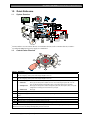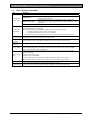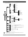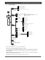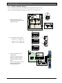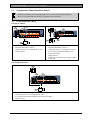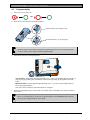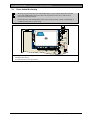
1
Easy Series (ICP-EZM2)
Installer Guide
EN
Intrusion Control Panel
Easy Series (ICP-EZM2) | Installer Guide | Contents
Contents
1.0
Quick Reference .................................................... 3
1.1 System Overview .................................................3
1.2 Control Center Overview ...................................3
1.3 Basic Operation Information..............................4
1.4 System Setup (Wired and Wireless) ..............5
1.5 Installer Phone Menu...........................................6
1.6 User Phone Menu ................................................7
2.0
Installation................................................................. 8
2.1 Enclosure Installation (Step 1)..........................8
2.2 Control Panel Board Installation (Step 2) ......9
2.3 Control Center Installation (Step 3) ............. 10
2.4 DX2010 Installation (Step 4) ......................... 12
2.5 Wireless Hub Installation (Step 5)................ 13
2.6 Supervised Point Connections (Step 6) ..... 14
2.6.1 Fire Point Wiring........................................ 14
2.6.2 Intrusion Point Wiring............................... 15
2.6.3 Keyswitch Wiring ...................................... 15
2.7 Programmable Output Connections (Step 7)
............................................................................... 16
2.7.1 Programmable Output 1 Wiring ............ 16
2.7.2 Programmable Outputs 2 to 4 Wiring . 17
2.8 Phone Line Connections (Step 8) ................ 18
2.9 Insert Voice Module (Step 9) ......................... 18
2.10 EZTS Connections (Step 10) ........................ 18
2.11 Power Supply Installation (Step 11)............. 19
2.11.1 EZPS Wire-in Power Supply.................. 19
2.11.2 Plug-in Power Supply............................... 21
2.11.3 12 VDC Standby Battery ........................ 21
2.12 Secure the Enclosure (Step 12) ................... 22
2.13 Program the Control Panel (Step 13).......... 22
2.14 Test the System (Step 14) ............................. 22
3.0
Point Expansion ...................................................23
3.1 Establishing the Wireless Network and
Configuring Wireless Devices ....................... 23
3.1.1 Discover New System.............................. 23
3.1.2 Establish and Configure the Wireless
Network ....................................................... 23
3.1.3 Configure Devices .................................... 24
3.1.4 Test Devices............................................... 24
3.2 Wireless Maintenance ..................................... 26
3.2.1 Wireless Configuration Menu ................ 26
3.2.2 Assigning Points 1 to 8 as Wireless
Points ........................................................... 27
3.2.3 DX2010 Input Expanders and Wireless
Points ........................................................... 27
3.2.4 Recovering the Wireless Network ........ 27
3.3 Wireless System Messages........................... 28
2
4.0
Programming ........................................................29
4.1 Enter Programming........................................... 29
4.2 Basic Programming .......................................... 30
4.2.1 Points ........................................................... 31
4.2.2 Report Configuration................................ 32
4.2.3 Outputs ....................................................... 33
4.2.4 Country Code ............................................ 34
4.3 Expert Programming......................................... 36
4.3.1 ROM Firmware Version Items ................ 37
4.3.2 System Programming Items ................... 37
4.3.3 Communicator Programming Items...... 41
4.3.4 Report Routing Programming Items..... 43
4.3.5 Point Programming Items........................ 46
4.3.6 Output Programming Items .................... 51
4.3.7 Control Center Programming Items ..... 52
4.3.8 User Programming Items......................... 53
4.3.9 Factory Default .......................................... 53
4.4 Exit Programming.............................................. 53
4.5 Programming Key.............................................. 54
4.6 Remote Programming Software (RPS) ....... 55
4.6.1 Installer Calls RPS .................................... 55
4.6.2 RPS Calls the Control Panel.................. 55
5.0
System Test...........................................................56
6.0
Maintenance ..........................................................56
7.0
Reference Materials...........................................57
7.1 Enclosure Wiring Label ................................... 57
7.2 Power-limited Wire Routing ........................... 58
7.3 Standby Battery Calculation .......................... 59
7.4 Event Report Codes......................................... 60
7.5 Display States.................................................... 62
7.6 Frequently Asked Questions (FAQ) ............. 64
7.6.1 Programming Questions ......................... 64
7.6.2 System Operation Questions................. 65
7.6.3 Control Center Questions ...................... 67
7.6.4 Passcode Questions................................ 67
7.7 Agency Approvals and Requirements.......... 68
7.7.1 Certifications and Approvals .................. 68
7.7.2 FCC.............................................................. 68
7.7.3 Industry Canada ........................................ 69
7.7.4 SIA................................................................ 69
7.7.5 Underwriters Laboratories (UL) ............. 71
7.7.6 EN50131-1 ................................................ 72
7.7.7 PD6662 and DD243 Requirements .... 73
7.7.8 INCERT ....................................................... 73
7.7.9 cUL ............................................................... 73
7.8 Specifications .................................................... 74
7.9 Compatible Options......................................... 76
Bosch Security Systems, Inc. | 10/06 | F01U025147C
Easy Series (ICP-EZM2) | Installer Guide | 1.0 Quick Reference
.
1.0 Quick Reference
1.1
System Overview
C=
C =12V
C =0V
2
3
4
5
6
7
8
NC C NO
1
12 VDC
2
1
Connect either a two-wire smoke detector or an intrusion detector, such as a motion detector, to Point 1.
2
Use either the EZPS wire-in power supply or a transformer.
1.2
Control Center Overview
9
1
2
8
3
4
5
7
6
Callout
1
2
3
Description
Press and hold [1] for two sec to start a fire alarm.
For an emergency alarm, press and hold [1] and [2] for two sec.
Press and hold [2] for two sec to start a panic alarm.
For an emergency alarm, press and hold [1] and [2] for two sec.
1
Press and hold [3] for 2 sec to enter User Menu, and then present token or enter passcode. Select an option :
Press [1]. Use this option to add a new user. You must assign a passcode. You can
• Add User:
also record a description and assign a token or key fob. Follow all voice prompts.
Press [2]. Use this option to add or change the passcode, description, token, or key fob
• Change User:
assigned to an existing user. Follow all voice prompts.
Press [3].
• Delete User:
4
5
Press and hold [4] for 2 sec to turn Chime Mode on or off.
Press and hold [5] for 2 sec to enter Volume Menu, and then press again to select a level: low, medium, high, or
quiet2.
6
Press [i] to turn the system on or off. Follow all voice prompts.
7
Speak into the audio interface to talk to someone on the telephone during a two-way voice session.
8
Present token to control center to turn the system on or off.
9
Control center display. Refer to Section 7.5 Display States on page 62 for more information.
1
Master user token or passcode required to access these options. Other users can change only their own passcodes.
2
Quiet Control Center: Exit Delay and Entry Delay tones are silenced.
Bosch Security Systems, Inc. | 10/06 | F01U025147C
3
Easy Series (ICP-EZM2) | Installer Guide | 1.0 Quick Reference
1.3
Basic Operation Information
Item
Description
House phone:
Press [#] three times, and enter a passcode.
Dial the house phone number, and press [*] three times when the call is
answered. Enter a passcode.
Connect a test telephone to the control panel’s test posts or telephone
Installer quick connect:
terminals. Press and hold the system test button for approximately 15 sec. Enter
a passcode.
Press [#] repeatedly until the system says “goodbye.”
End a phone session:
Start a phone session (refer to options above).
Enter installer passcode when prompted.
From the Installer Menu, press [3] for basic programming, or [4] for expert programming.
For Basic Programming, refer to Section 4.2 on page 30.
- For Expert Programming, refer to Section 4.3 on page 36.
To exit programming, press [#] repeatedly until you hear the system announce the Installer Menu options.
Options are four digits or six digits. Selection affects all passcode lengths.
Expert programming →Expert Programming Item Number 861.
Outside phone:
Start and end a
phone session
Enter and exit
programming
Passcode length
Installer
passcode
Master user
passcode
Factory default
Add or change
users
System Test
“Call for
Service” Details
4
Four-digit default = 5432; six-digit default = 543211 (Expert Programming Item Number 7011).
Four-digit default = 1234; six-digit default = 123455. (Expert Programming Item Number 7001).
In expert programming, enter Expert Programming Item Number 9999. Doing this restores all factory default
values. All programming items, except for the country code, are reset when you restore the factory default
values. All recorded speech items are unaffected.
Start a phone session, or press and hold [3] on the control center (refer to Section 1.2 Control Center
Overview on page 3).
Enter the master user passcode.
Press [4] to select the User Menu.
Press [1] to add a new user, or press [3] to change an existing user. Follow all voice prompts.
When you add a new user or change an existing user, you can also assign a token or key fob.
On the control panel board, press the System Test button once to start the System Test.
Enter the installer passcode when you hear the “Call for Service” message.
The system announces the system trouble condition and then asks you to select a menu option.
Bosch Security Systems, Inc. | 10/06 | F01U025147C
Easy Series (ICP-EZM2) | Installer Guide | 1.0 Quick Reference
.
1.4
System Setup (Wired and Wireless)
After the system is installed and configured, add key fobs when you add users.
Wireless support is not investigated by UL.
To install an Easy Series Intrusion Control Panel with wireless devices:
1.
Follow all instructions in the wLSN Reference Guide (P/N: F01U009440) to verify adequate signal strength
exists at each device location.
2.
Install all hard-wired devices, such as the control panel, control center, input and output devices, DX2010
Input Expanders, and the wireless hub.
Refer to the installation instructions supplied with each device for specific installation and configuration
instructions.
The control panel assigns wireless point numbers based on whether or not one or more DX2010
Input Expanders are connected to the control panel.
3.
Install the bases for all wireless devices.
4.
Apply power to the control panel.
5.
Start the System Test:
- From Phone:
1. Start a phone session.
Refer to Section 1.3 Basic Operation Information on page 4 for instructions.
2. From the Installer Phone Menu, press [1] for System Maintenance.
3. Press [2] for Full System Test.
Refer to Section 1.5 Installer Phone Menu on page 6.
- From Control Panel: To start the full system test, press and hold the System Test button for one
second. Refer to Section 5.0 System Test on page 56 for more information.
6.
When the system announces “Install all batteries,” install the batteries or remove the battery tabs from all
wireless devices. Mount the device covers on the bases.
7.
When all batteries are installed and device covers are mounted, press [1] on the phone or control center to
continue.
The system identifies (discovers) new wireless devices on the system. This process takes up to 4 min to
complete. When the discovery process is complete, the system announces the number of devices
discovered.
8.
When the system announces “Test all points,” test each device (fault and restore), including wireless inputs
and outputs.
Refer to Section 3.1.4 Test Devices on page 24 for more information.
Point numbers are assigned to wireless devices in the order that the devices are tested (tampered
or faulted and restored). If specific point numbers are preferred for wireless devices, ensure that the
wireless devices are tested in the appropriate order. Otherwise, the system assigns the lowest
available point number to the first tested wireless device.
9.
As you test each device, complete Section 4.3.5 Point Programming Items on page 46, and Section 4.3.6 Output
Programming Items on page 51.
When you restore the device, the system announces the assigned device number.
Complete Sections 4.3.5 and 4.3.6 as you test the inputs and outputs. Otherwise, you cannot cross-reference
point numbers to point descriptions in the event of a point trouble.
The control panel completes the remaining system tests and notifies you when they are complete.
10. When the control panel completes all system tests, enter Basic Programming. You can also use RPS to
program the control panel.
Bosch Security Systems, Inc. | 10/06 | F01U025147C
5
Easy Series (ICP-EZM2) | Installer Guide | 1.0 Quick Reference
1.5
Installer Phone Menu
1
Set date and time
1
Warning device test
2
Full system test
2
Battery test
3
Communication test
4
Control center test
3
System test menu
5
Point test
6
Operate Outputs
#
Exit system test menu
1
Most recent events
2
Events by date
3
Last alarm event
4
Last 10 events
#
Exit event history
1
System
Maintenance
4
Event history
5
Reset system
6
#
2
Installer
Phone
Menu
Exit system maintenance
1
Change installer passcode
2
Change master user (User 1) passcode
#
Exit user menu
1
Points
2
4
3
1
Record point description
2
Set point type
#
Exit points
Report Configuration
3
Basic
Programming
1
Select output function
5
6
Custom
Messages
7
Programming
Key
#
=
6
2
Add a device
3
Delete a device
4
Transfer wireless data
(control panel-to-hub)
5
Transfer wireless data
(hub-to-control panel)
6
Erase and discover
#
Exit Wireless configuration
1
Enter account number
2
Configure report destinations
#
Exit report configuration
#
Exit outputs
Outputs
4
Country Code
#
Exit basic programming
Enter programming item, enter selection.
Expert
Programming
Two-Way
Voice Session
Replace a device
Wireless configuration
Installer passcode
4-digit default: 5432
6-digit default: 543211
User Menu
1
}
}
1
Talk to person at control center
2
Listen to person at control center
#
End voice session
1
Record site description
2
Record call for service message
#
Exit custom messages
1
Send data from key to control panel (key position =
)
2
Send data from control panel to key (key position =
)
#
Exit programming key
The voice session only lasts 90 seconds.
To reset the timer, press [1] on the phone during talk mode, or
[2] during listen mode.
Only the person on the phone can switch between talk and listen
modes.
Custom messages are stored in the voice module, and are not
saved with the control panel's programming data.
Exit installer menu and end phone session.
The system’s arming status (on or off) and Expert Programming Item Number 142’s setting of (0 or 1)
determines the availability of these menu items.
Bosch Security Systems, Inc. | 10/06 | F01U025147C
Easy Series (ICP-EZM2) | Installer Guide | 1.0 Quick Reference
.
1.6
User Phone Menu
1
Turn System On or Off
Only use this option
on non-UL systems.
2
Enter user
passcode1
Two-Way
Voice Session
Phone
Menu
1
Turn system on and stay inside
2
Turn system on and leave
3
Turn on custom protection
#
Exit
To hear this option, custom protection must be enabled.
1
Talk to person at control center
2
Listen to person at control center
#
End voice session
1
Set date and time
2
Full system test
3
System test menu
3
System
Maintenance2
4
4
User Menu3
}
The voice session only lasts 90 seconds.
To reset the timer, press [1] on the phone during talk mode,
or [2] during listen mode.
1
Warning device test
2
Battery test
3
Communication test
4
Control center test
5
Point test
6
Operate outputs
OR
Expert Programming (Enable Installer Access)4
#
Exit system test menu
1
Most recent events
2
Events by date
3
Last alarm event
4
Last 10 events
#
Exit
Event history
5
Reset system
#
Exit
1
Add new user
2
Change user
3
Delete user
#
Exit
}
To add or change a user:
1
Change token
2
Record description
3
Change passcode
4
Change key fob
#
Exit
Only the Master User can
access the full User Menu.
Users 2 to 21 can only change
their own passcode.
5
Operate Outputs
To turn an output on or off, press the
corresponding number key on the phone.
#
Exit
End phone session.
1
Only a user passcode (Users 1 to 21) can access the User Menu.
2
If the system is on, the System Maintenance option is not available.
3
Only the master user can add, change, or delete users. Users 2 to 21 can only change their own passcodes.
User voice descriptions are stored in the voice module and are not transferred to the control panel with
programming data.
4
Option 6 allows the master user (User 1) to enable the Installer Passcode. Refer to Expert Programming Item
Number 142 on page 39 for more information.
Availability of the menu items shown above depends on the system’s status.
Bosch Security Systems, Inc. | 10/06 | F01U025147C
7
Easy Series (ICP-EZM2) | Installer Guide | 2.0 Installation
2.0 Installation
Only use authorized service personnel to install this system.
Because the control panel is permanently connected equipment, a readily accessible disconnect
device must be included into the building installation wiring.
Follow anti-static procedures when handling the control panel board.
Touch the earth ground terminal on the control panel board to discharge any static charge before
working on the control panel board.
To aid in system installation, this section is divided into sub-sections and labeled in a step-by-step format. Each
sub-section, or major step, might consist of several minor steps that must be completed before proceeding to
the next sub-section or major step.
2.1
Enclosure Installation (Step 1)
Use proper anchor and screw sets when installing the enclosure on non-load-bearing surfaces,
such as drywall.
1.
Mount the optional EZTS Tamper Switch.
If a wall tamper is required, insert the round plastic wall plug
before mounting the enclosure.
Refer to the EZTS Cover or Wall Tamper Switch Installation
Guide (P/N: F01U003734) for complete installation
instructions.
Refer to Programming Item 137 on page 39 for enclosure
tamper options.
2.
8
Mount the enclosure. Screws not supplied.
Bosch Security Systems, Inc. | 10/06 | F01U025147C
Easy Series (ICP-EZM2) | Installer Guide | 2.0 Installation
.
2.2
Control Panel Board Installation (Step 2)
1.
Place the mounting clips on the enclosure
standoffs.
2.
Place the top edge of the control panel board
between the enclosure retaining slots, and then
set the control panel board on the mounting
clips.
3.
Secure the control panel board to the mounting
clips using the supplied screws.
=
Bosch Security Systems, Inc. | 10/06 | F01U025147C
9
Easy Series (ICP-EZM2) | Installer Guide | 2.0 Installation
2.3
Control Center Installation (Step 3)
For complete control center installation instructions, refer to the EZ1 Control Center Installation Guide
(P/N: F01U003737) included with the control center.
To ensure proper RF ID reader operation, mount the control center only on a non-metallic surface.
If you install more than one control center, ensure that there is at least 1.2 m (4 ft) of space between each
control center.
1.
Set the address on the control center.
The control panel supports up to four
control centers.
Each control center must have a different
address. Valid addresses are 1 to 4.
The address switch is located on the inside
of the control center.
BGYR
2.
Connect the control center data bus
terminals to the control panel data bus
terminals.
3.
Connect the control center audio bus
terminals to the control panel audio bus
terminals.
Twisted pair wiring is recommended for
audio bus connections.
If CAT5 cable is used, refer to the following
CAT5 figure.
+ -
10
Bosch Security Systems, Inc. | 10/06 | F01U025147C
Easy Series (ICP-EZM2) | Installer Guide | 2.0 Installation
.
CAT5 Cable Connections
1
7
+
R
Y
G
B
4
5
3
6
2
1234-
Control center audio bus terminals
Control center data bus terminals
CAT5 cable
Blue and blue-and-white-striped
conductors (twisted pair)
8
5678-
Bosch Security Systems, Inc. | 10/06 | F01U025147C
Solid color conductors
White striped conductors
Control panel board audio bus terminals
Control panel board data bus terminals
11
Easy Series (ICP-EZM2) | Installer Guide | 2.0 Installation
2.4
DX2010 Installation (Step 4)
The control panel supports up to three DX2010 Input Expanders for Points 9 to 32.
Refer to the DX2010 Installation Instructions (P/N: 49533) for more information.
1.
Mount the DX2010 into the
control panel’s enclosure, or other
suitable enclosure.
=
102
2.
Set the DX2010’s DIP switches.
-
Points 9 to 16 = Address 102
-
Points 17 to 24 = Address 103
-
Points 25 to 32 = Address 104
ON
103
OFF
104
3.
Connect the DX2010 to the
control panel.
Connect a wire jumper to the
TMPR and COM terminals to
disable the DX2010’s tamper
input.
For point wiring options, refer to
Section 2.6 Supervised Point
Connections on page 14.
12
+OUT-
TMPR
R
B
G
Y
B
1 COM
G
Y
R
Bosch Security Systems, Inc. | 10/06 | F01U025147C
Easy Series (ICP-EZM2) | Installer Guide | 2.0 Installation
.
2.5
Wireless Hub Installation (Step 5)
Before installing the wireless hub or any wireless devices, refer to Section 3.0 Point Expansion on
page 23, the ISW-BHB1-WX Installation Instructions (P/N: F01U500915), the wLSN Reference
Guide (P/N: F01U009440), and the installation instructions supplied with each wireless device.
1.
Perform a site test as described in the
wLSN Reference Guide.
2.
Set the S1 switch on the wireless hub to
Address 50 (Position 1).
The control panel supports one wireless
hub.
Switches S2 and S3 are not used for device
addressing.
S1
S2
S3
5
5
5
0
0
0
R B G Y
3.
Connect the hub to the control panel.
4.
Put the cover on the wireless hub and lock
the cover to the hub.
5.
Install the wireless device bases as
described in their installation instructions.
Bosch Security Systems, Inc. | 10/06 | F01U025147C
13
Easy Series (ICP-EZM2) | Installer Guide | 2.0 Installation
2.6
Supervised Point Connections (Step 6)
Separate primary AC power and standby battery wires from all power-limited wiring. Refer to
Section 7.2 Power-limited Wire Routing on page 58 for more information.
2.6.1
Fire Point Wiring
Supervised Point 1 supports two- and four-wire smoke detectors.
Supervised Points 2 to 32 support only four-wire smoke detectors.
To program supervised points as fire points, refer to Section 4.2.1 Points on page 31.
For intrusion point configuration, refer to Section 2.6.2 Intrusion Point Wiring on page 15.
1
2
3
1
2
1
2
4
5
6
4
3
3
3
4
5
6
7
8
Two-wire smoke detector wiring
1 - Power-in terminal
2 - Power-out terminal
3 - Common (negative) terminal
4 - 2.2 k Ω end-of-line resistor (P/N: 25899)
Four-wire smoke detector wiring
1 - Supervised Points 1 to 32
(Point 8 shown in figure)
2 - Programmable Output (PO)
(PO 2 shown in figure)
3 - Power-in terminal
4 - Power-out terminal
5 - Alarm terminals
6 - Common (negative) terminal
7 - End-of-line resistor (P/N: 25899)
8 - Bosch EOL200 End-of-Line Module
Refer to the Easy Series Smoke Detector Compatibility List (P/N: F01U004853) for compatible two-wire smoke
detectors.
When using an output to supply power to a four-wire smoke detector, program the output function
for System Reset. Refer to Section 4.2.3 Outputs on page 33.
14
Bosch Security Systems, Inc. | 10/06 | F01U025147C
Easy Series (ICP-EZM2) | Installer Guide | 2.0 Installation
.
2.6.2
Intrusion Point Wiring
Refer to the figures below to wire Supervised Points 1 to 32 as wired or wireless intrusion points.
To program Supervised Points 1 to 32 as intrusion points, refer to Section 4.2.1 Points on page 31.
For fire point configuration, refer to Section 2.6.1 Fire Point Wiring on page 14.
1
1
1
5
2
5
4
4
6
3
4
2
Single 2.2 kΩ EOL resistor
1 - Supervised point
(on-board, DX2010, or
wireless input)
2 - 2.2 kΩ EOL resistor
3 - Alarm terminals
(Normally Open)
4 - Alarm terminals
(Normally Closed)
2.6.3
3
Dual 2.2 kΩ Resistors
(Point Tamper*)
1 - Supervised point
(on-board, DX2010, or
wireless input)
2 - Alarm terminals
(Normally Closed)
3 - Tamper terminals
(Normally Closed)
4 - 2.2 kΩ EOL resistor
5 - 2.2 kΩ alarm resistor
* This option is not allowed by UL.
2
3
Dual 2.2 kΩ Resistors
(Point Tamper*)
1 - Supervised point (on-board,
DX2010, or wireless input)
2 - Alarm terminals
(Normally Closed)
3 - Tamper terminals
(Normally Closed)
4 - 2.2 kΩ end-of-line resistor
5 - 2.2 kΩ alarm resistor
6 - Additional devices
(up to 4 maximum)
* This option is not allowed by UL.
Keyswitch Wiring
Refer to the figure below to wire Supervised Points 1 to 32 as keyswitch points (Point 2 shown in figures).
To program Supervised Points 1 to 32 as keyswitch points, refer to Section 4.2.1 Points on page 31.
1
1
2
2
3
3
Single 2.2 kΩ end-of-line resistor option
1 - Supervised point
(on-board, DX2010, or wireless device)
2 - 2.2 kΩ resistor
3 - Normally-open momentary or maintained
keyswitch
Bosch Security Systems, Inc. | 10/06 | F01U025147C
Dual 2.2 kΩ resistors (point tamper option)
1 - Supervised point
(on-board, DX2010, or wireless device)
2 - 2.2 kΩ resistor
3 - Normally-closed momentary or
maintained keyswitch
15
Easy Series (ICP-EZM2) | Installer Guide | 2.0 Installation
2.7
Programmable Output Connections (Step 7)
Separate primary AC power and standby battery wires from all power-limited wiring. Refer to
Section 7.2 Power-limited Wire Routing on page 58 for more information.
2.7.1
Programmable Output 1 Wiring
Switched 12 V Option
1
2
1
2
3
(+)
(-)
(+) (-)
4
+ -
5
3
Warning device (without battery)
1 - Programmable Output 1 (PO 1)
2 - Jumper plug position for switched 12 V option
3 - Warning device
Warning device (with battery)
1 - Programmable Output 1 (PO 1)
2 - Jumper plug position for switched 12 V option
3 - Control panel board white auxiliary power
terminals (12 VDC)
4 - Warning device
5 - Warning device activates when trigger voltage
is removed
Switched Ground Position
3
2
1
(+) (-)
4
1234-
16
Programmable Output 1 (PO 1)
Jumper plug position for switched ground option
Control panel board white auxiliary power terminals (12 VDC)
Warning device
Bosch Security Systems, Inc. | 10/06 | F01U025147C
Easy Series (ICP-EZM2) | Installer Guide | 2.0 Installation
.
Dry Contact Option
1
2
3
(+)
(-)
4
1234-
2.7.2
Programmable Output 1 (PO 1)
Jumper plug position for dry contact option (no jumper)
Warning device (normally-open option)
Power source
Programmable Outputs 2 to 4 Wiring
2
3
4
1
2
3
4
7
(+)
(-)
(+) (-)
5
1
+ -
8
6
5
Warning device (without battery)
1 - Warning device (PO 2, 3, or 4)
2 - Programmable Output 2 (PO 2)
3 - Programmable Output 3 (PO 3)
4 - Programmable Output 4 (PO 4)
5 - 8 Ω speaker (PO 4 option only)
Warning device (with battery)
1 - Programmable Output 2 (PO 2)
2 - Programmable Output 3 (PO 3)
3 - Programmable Output 4 (PO 4)
4 - Control panel board white auxiliary power
terminals (12 VDC)
5 - Warning device (PO 2, 3, or 4)
6 - Trigger voltage
7 - 10 k Ω resistor
(Refer to warning device instructions for
recommended resistor value)
8 - Warning device activates when the
programmable output activates
If you program PO 4 as a supervised speaker driver, connect an 8 Ω speaker to prevent speaker
supervision troubles. Refer to Expert Programming Item Number 642 on page 51 for more
information.
For a UL-approved installation, only connect a UL listed, 85 dB sounding device to PO 4.
Bosch Security Systems, Inc. | 10/06 | F01U025147C
17
Easy Series (ICP-EZM2) | Installer Guide | 2.0 Installation
2.8
Phone Line Connections (Step 8)
Connect the incoming phone line and the house
phone to the control panel board.
2.9
Insert Voice Module (Step 9)
The voice module is required for system
operation.
2.10
EZTS Connections (Step 10)
If the optional EZTS Tamper Switch was
installed in Step 1 on page 8, connect its cable to
the two-pin connector on the control panel.
18
Bosch Security Systems, Inc. | 10/06 | F01U025147C
Easy Series (ICP-EZM2) | Installer Guide | 2.0 Installation
.
2.11
Power Supply Installation (Step 11)
This system uses either the EZPS wire-in power supply, OR a plug-in power supply. Both power
supplies require the enclosure ground wire and a standby battery.
Follow the instructions below for the power supply used in your installation.
The EZPS is not investigated by UL.
2.11.1 EZPS Wire-in Power Supply
1.
Mount the EZPS on the enclosure using
the screws supplied with the EZPS.
2.
Connect the earth ground wire from the
EZPS to the enclosure stud.
3.
EZPS
L
N
Connect AC power to the EZPS.
EZPS
100-240 V
0.5 A MAX
47-62 Hz
Bosch Security Systems, Inc. | 10/06 | F01U025147C
L
N
19
Easy Series (ICP-EZM2) | Installer Guide | 2.0 Installation
4.
Connect the EZPS wires to the
control panel board.
5.
Insert the door hinges onto the
enclosure.
6.
Push the enclosure ground wire
connector onto the unpainted
part of the door’s top hinge.
5
7.
Connect the enclosure ground
wire to the threaded enclosure
stud.
8.
Connect the enclosure ground
wire to the control panel
board’s earth ground terminal.
6
8
7
EZPS
20
Bosch Security Systems, Inc. | 10/06 | F01U025147C
Easy Series (ICP-EZM2) | Installer Guide | 2.0 Installation
.
2.11.2 Plug-in Power Supply
1.
Connect a ground wire from the enclosure to a good
earth ground source.
2.
Connect the enclosure ground wire.
For instructions, refer to Steps 5 to 8 in Section 2.11.1
EZPS Wire-in Power Supply on page 19.
3.
Connect the plug-in power supply to the control panel
board.
3
2
1
2.11.3 12 VDC Standby Battery
When all system wiring is complete, apply AC and standby
battery power to the control panel.
(+)
(-)
12 VDC
Bosch Security Systems, Inc. | 10/06 | F01U025147C
21
Easy Series (ICP-EZM2) | Installer Guide | 2.0 Installation
2.12
Secure the Enclosure (Step 12)
To secure the enclosure door:
•
Install the enclosure door lock, or
•
Secure the door with screws.
Screws not supplied.
OR
2.13
Program the Control Panel (Step 13)
When installation is complete, you can program the control panel.
Refer to Section 4.0 Programming on page 29 for more information.
2.14
Test the System (Step 14)
When programming is complete, you must test the system for proper operation.
Refer to Section 5.0 System Test on page 56 for more information.
22
Bosch Security Systems, Inc. | 10/06 | F01U025147C
Easy Series (ICP-EZM2) | Installer Guide | 3.0 Point Expansion
.
3.0 Point Expansion
For complete wireless installation and configuration information, refer to the wLSN Reference Guide
(P/N: F01U009440) supplied with the wireless hub, and the installation instructions supplied with each wireless
device.
Wireless support is not investigated by UL.
3.1
Establishing the Wireless Network and Configuring Wireless Devices
In order for the wireless network to operate properly, the following process must occur as shown below.
Inputs and Outputs
(Point Test)
Discover
Devices
Establish
Network
Configure
Network
Configure
Devices
Key Fobs
(Add/Change User Menu)
3.1.1
Discover New System
Discovery is the process through which the wireless hub identifies and includes new (undiscovered)
devices into the system.
You can only perform the new system discovery process once. To update an existing wireless
system, refer to Section 3.2 Wireless Maintenance on page 26.
There are three ways to start the discovery process on a new system:
•
System Test Button:
1. Ensure that all devices have exited RFSS Mode.
2. Press and hold the System Test button for one second.
The device discovery process automatically starts at the beginning of the Point Test.
•
Wireless Configuration Menu:
1. Start a phone session.
Refer to Section 1.3 System Setup on page 5 for phone session options.
2. From the Installer Menu, select System Maintenance, and then select Wireless Configuration.
The device discovery process automatically starts.
•
Point Test:
1. Start a phone session.
Refer to Section 1.3 System Setup on page 5 for phone session options.
2. From the Installer Menu:
- Press [1] to select System Maintenance, and then press [2] to select Full System Test.
The discovery process starts at the beginning of the Point Test.
OR
- Press [1] to select System Maintenance, and then press [3] to select System Test Menu. From the
System Test Menu, press [5] to select Point Test.
The discovery process starts at the beginning of the Point Test.
3.1.2 Establish and Configure the Wireless Network
The wireless hub automatically establishes and configures the wireless network.
The wireless hub evaluates each available radio frequency (RF) for noise, RF signal strength, and other
adjacent wireless systems. The wireless hub then selects the frequency with the lowest amount of noise and
least amount of traffic for network operation.
To configure the wireless network, the wireless hub selects the best channel for broadcasting. Once a channel
is selected, the wireless hub then configures all discovered devices to operate on the selected frequency. This
process takes several minutes.
Bosch Security Systems, Inc. | 10/06 | F01U025147C
23
Easy Series (ICP-EZM2) | Installer Guide | 3.0 Point Expansion
3.1.3
Configure Devices
Input and Output Devices
The ISW-BMC1-S135X Door/Window Contact and the ISW-BIN1-S135X Inertia Detector have a
magnetic switch as an input. If the magnetic switch is not used, remove the magnet from the device
before starting the Point Test.
Once the network is established and configured, the system announces “Test all points.” Test the wireless
devices in this order: input devices, output devices, and relay modules.
Do not exit the Point Test until all intended wireless devices are tested. Otherwise, you must
manually add devices to the system.
If extra wireless devices not intended for installation are within the wireless hub’s range, the hub
might also discover these devices. To exclude any unused devices from the system, press [#] (or [5]
from the control center) to exit the Point Test. The wireless hub returns all unused devices to the
undiscovered state.
As you test each device, complete Section 4.3.5 Point Programming Items on page 46, and Section 4.3.6 Output
Programming Items on page 51.
When you restore the device, the system announces the assigned device number.
3.1.4
Test Devices
Point numbers are assigned to wireless devices in the order that the devices are tested (tampered
or faulted and restored). If specific point numbers are preferred for wireless devices, ensure that the
wireless devices are tested in the appropriate order. Otherwise, the system assigns the lowest
available point number to the first tested wireless device.
Refer to the following table for instructions on testing each wireless device.
Device
Motion Detectors
Smoke Detector
Relay Module
Inertia Detector
Glass Break Detector
Mini Door/Window Contact
Recessed Door/Window Contact
Door/Window Contact
Siren
To Test:
Walk across the detector’s coverage pattern.
•
Press and release the detector’s test button, or
•
Blow smoke into the detector’s chamber to cause an alarm. Restore the
alarm.
•
Input: Fault and restore the supervised loop.
•
Output: Tamper the device.
Perform both tests only if both the input and output are used.
•
Magnetic Switch: Open and then close the switch.
1
•
Inertia Only: Cause an alarm and then restore the alarm , or tamper the
3
detector.
2
3
Cause an alarm and then restore the alarm , or tamper the detector.
Open and then close the magnetic switch.
•
Open and then close the magnetic switch, or
•
Fault and then restore the supervised loop.
Perform both tests only if both the magnetic switch and supervised loop are
used.
Tamper the device.
1
To test the inertia detector, create a shock to cause an inertia alarm, and then restore alarm.
2
To test the glass break detector, use a special tool to cause a glass break alarm, and then restore the alarm.
3
If you tamper the detector, the control panel enrolls the detector, but does not test it. You must create the
appropriate alarm and restore the alarm to test the detector.
24
Bosch Security Systems, Inc. | 10/06 | F01U025147C
Easy Series (ICP-EZM2) | Installer Guide | 3.0 Point Expansion
.
Key Fobs
Add key fobs after all other wireless devices (inputs and outputs) are discovered and configured.
1.
After the last wireless device is configured and the Point Test ends, press [#] repeatedly until you exit the
Installer Menu and end the phone session.
2.
Start a new phone session, or press and hold [3] on the control center, and enter the master user (User 1)
passcode.
3.
Press [4] to select the User Menu.
4.
Press [1] to add a new user.
5.
Enter a passcode.
6.
Re-enter the passcode.
7.
Press [4] to add a key fob.
Token assignment and voice description are optional.
8.
Repeat Steps 4 to 7 to add more users and key fobs, or press [#] repeatedly to end the phone session.
To create a key fob-only system (no wireless input or output devices installed), start at Step 2.
In a key fob-only system, adding the first key fob might take several minutes to complete as the wireless
network is established and configured. Subsequent key fob additions take less time.
Bosch Security Systems, Inc. | 10/06 | F01U025147C
25
Easy Series (ICP-EZM2) | Installer Guide | 3.0 Point Expansion
3.2
Wireless Maintenance
3.2.1
Wireless Configuration Menu
Use the Wireless Configuration Menu to:
•
Add new wireless devices to an existing wireless system
•
Add wireless devices that were not discovered when the wireless network was first discovered
•
Replace or delete wireless devices from an existing wireless system
To access the Wireless Configuration menu:
1.
Start a phone session.
Refer to Section 1.3 System Setup on page 5 for phone session options.
2.
From the Installer Menu, press [1] for System Maintenance.
3.
From System Maintenance, press [6] for Wireless Configuration.
Refer to the following table for menu options and descriptions. Menu options are only available after the
initial device discovery and point test is completed.
Button Press
[1]
Menu Option
Replace a Device
Description
Use this option to replace a known device with a new device.
1. Press [1] to replace a point, or [3] to replace an output.
For a relay module, select either the input or output, and then enter
the appropriate number in Step 2.
2. Enter the desired point number or output number.
The device discovery process starts.
3. When the system announces “Test all points,” activate the new
device.
The new device replaces the current device. If other devices were
discovered in Step 2, they are returned to the undiscovered state.
[2]
Add a Device
Use this option to add more devices to the wireless network.
When you press [2] to select this option, the device discovery process
starts. When the system announces “Test all points,” activate all of the
new devices.
If other devices were discovered but not activated, they are returned to
the undiscovered state.
[3]
Delete a Device
Use this option to delete a known device from the system.
1. Press [1] to delete a point, or [3] to delete an output.
2. Enter the desired point number or output number.
If the selected point number corresponds with a relay module, both
the input and output are deleted from the system. If you only want
to delete the input or the output, you must disable the
corresponding function through programming.
3. Press [1] to delete the device.
The wireless hub deletes the device from the system, and the point
type or output function is set to 0 (Disabled).
[4]
[6]
Transfer Wireless Data
(control panel-to-hub)
Transfer Wireless Data
(hub-to-control panel)
Erase and Discover
[#]
Exit Wireless Configuration
If you replace a hub, select this option to send wireless data from the
control panel to the wireless hub.
If you replace the control panel, select this option to send wireless data
from the wireless hub to the control panel. This option deletes key fobs.
If the wireless data in the control panel does not match the wireless data
in the hub (Bus Device Trouble 50), use this option to erase the
wireless data in both the control panel and hub, and rediscover all
devices.
This option is only available if the wireless data does not match in the
control panel and hub.
Select this option to return to the System Maintenance options.
[5]
26
Bosch Security Systems, Inc. | 10/06 | F01U025147C
Easy Series (ICP-EZM2) | Installer Guide | 3.0 Point Expansion
.
3.2.2
Assigning Points 1 to 8 as Wireless Points
To assign an on-board point (1 to 8) as a wireless point, disable the point in programming before starting the
device discovery process.
You can individually assign Points 1 to 8 as wireless points.
3.2.3
DX2010 Input Expanders and Wireless Points
If Points 9 to 32 contain wired and wireless points, install all required DX2010 Input Expanders
before adding any wireless points to the system.
Adding a DX2010 Before Adding Wireless Points
The control panel supports up to three DX2010 modules. Each module occupies a group of eight points.
The DX2010’s DIP switch address determines which group of points the DX2010 occupies:
•
Address 102: DX2010 occupies Points 9 to 16
•
Address 103: DX2010 occupies Points 17 to 24
•
Address 104: DX2010 occupies Points 25 to 32
Refer to Section 2.4 DX2010 Installation on page 12 for more DIP switch settings.
As each DX2010 module is added to the system, it occupies the next available group of points.
For Points 9 to 32, wireless points also occupy points in the same groups of eight as the DX2010 modules:
•
If you add a DX2010 module using Address 102 (Points 9 to 16), wireless points can only occupy
Points 17 to 32.
•
If you add two DX2010 modules using Addresses 102 (Points 9 to 16) and 103 (Points 17 to 24),
wireless points can only occupy Points 25 to 32.
•
If you add three DX2010 modules, wireless points can only occupy Points 1 to 8.
Adding a DX2010 After Adding Wireless Points
If you add a DX2010 module after wireless points are added, based on its DIP switch address, the DX2010
replaces the conflicting group of wireless points.
For example, if wireless points occupy Points 9 to 24, and you need Points 17 to 24 as wired points, a DX2010
module with Address 103 replaces the wired points occupying Points 17 to 24.
If the next point grouping is available, for this example, Points 25 to 32, the control panel retains all point
programming except for voice descriptions, and moves the conflicting wireless points to the next point
grouping. You must re-record voice descriptions for the points that were moved.
If the next point grouping is not available, the control panel deletes the conflicting wireless points from the
system.
3.2.4
Recovering the Wireless Network
Expert Programming Item Number 9999 restores the control panel to its factory default settings. All wireless
network data in the control panel is lost, but is retained in the wireless hub.
To recover wireless network data from the wireless hub:
1.
Start a phone session.
2.
Press [1] to select System Maintenance.
3.
Press [6] to select the Wireless Configuration Menu.
4.
Press [5] to transfer wireless data from the hub to the control panel.
This option deletes key fob assignments. You must reassign all key fobs.
Bosch Security Systems, Inc. | 10/06 | F01U025147C
27
Easy Series (ICP-EZM2) | Installer Guide | 3.0 Point Expansion
3.3
Wireless System Messages
Refer to the following table for a description of system messages that pertain to the wireless network.
System Message
“Wireless devices not configured.”
“Extra device ignored.”
“Point x was tested.”
“Point x low.”
“Please wait.”
“Wireless error.”
“Wireless devices x.”
“Wireless devices not tested x.”
“Point x not tested.”
28
Description
Point Test was exited before all wireless points were tested.
An attempt was made to add a device to a system that already contains
the maximum number of points or outputs.
A point was tested. RFSS is acceptable.
A point was tested. RFSS is unacceptable.
The wireless network is busy, or the control panel is waiting for the
wireless network to respond.
The control center might show a single rotating segment of the circle of
protection with this message.
The wireless hub is jammed, missing, or experiencing a trouble
condition.
“x” = the number of devices that are discovered, but not tested.
“x” = the number of devices that are discovered, but not yet configured.
The control panel assigned a point number to the device, but the device
was not tested (faulted, or tampered, and restored).
“x” = the voice description.
By default, the system announces the point number.
Bosch Security Systems, Inc. | 10/06 | F01U025147C
Easy Series (ICP-EZM2) | Installer Guide | 4.0 Programming
.
4.0 Programming
4.1
Enter Programming
Select one of the following methods to enter the Installer Menu:
Method
House Phone
Outside Phone
Steps
1. Press [#][#][#].
2. Listen for the voice prompt to enter a passcode.
3. Enter the installer passcode.1
4. Press [3] for basic programming, or [4] for expert programming.
1. Call the premises phone number.
2. After the call is answered by either a person or a telephone answering device, press [*][*][*] to
disconnect the answering party and access the system.
If the phone is not answered by a person or telephone answering device, the system answers
after a programmed number of rings. Refer to Expert Programming Item Number 222 on page
42.
3. Listen for the voice prompt to enter a passcode.
4. Enter the installer passcode.1
5. Press [3] for basic programming, or [4] for expert programming.
Installer Quick
2
Connect
1.
Connect a phone set to either
the test posts or the phone
terminals.
2.
Press and hold the System
Test button for approximately
15 sec.
OR
15 s
3. Listen for the voice prompt to enter a passcode.
4. Enter the installer passcode.1
5. Press [3] for basic programming, or [4] for expert programming.
RPS
Refer to Section 4.6 Remote Programming Software (RPS) on page 55 for more information.
1
If the passcode length = four digits, the default installer passcode is 5432. If the passcode length = six digits, the default
installer passcode is 543211. Refer to Section 4.3.8 User Programming Items on page 53 to change the passcode
length and the installer passcode.
2
Select the installer quick connect method if a phone line is not available, or a local connection is required. The system
must be off to use this method.
First Time Programming
1. Set the country code to the appropriate code for your installation before making any other
programming changes.
This selection sets control panel’s defaults to the appropriate country-specific values. Refer to
Section 4.2.4 Country Code on page 34.
2. Set the time and date. Refer to Section 1.5 Installer Phone Menu on page 6.
Bosch Security Systems, Inc. | 10/06 | F01U025147C
29
Easy Series (ICP-EZM2) | Installer Guide | 4.0 Programming
4.2
Basic Programming
Basic programming consists of a voice menu that contains the essential programming items. Generally,
finishing this programming section is usually all that is required for a complete system
1
System
Maintenance
2
User Menu
1
2
Points
Basic
Programming
3
Record point description
2
Set point type
#
Exit points
Report Configuration
3
Installer passcode
4-digit default: 5432
6-digit default: 543211
1
1
Select output function
#
Exit outputs
1
Enter account number
2
Configure report destinations
#
Exit report configuration
Outputs
4
Country Code
#
Exit basic programming
4
Installer
Phone
Menu
Expert
Programming
5
Two-Way
Voice Session
6
Custom
Messages
7
Programming
Key
#
30
Exit installer menu and end phone session.
Bosch Security Systems, Inc. | 10/06 | F01U025147C
Easy Series (ICP-EZM2) | Installer Guide | 4.0 Programming
.
4.2.1
Points
You cannot program any wireless points without first completing the steps in Section 1.4 System
Setup on page 5.
Points
Enter a point number from 1 to 32.
1
Record Point Description
For example, if Point 1 is located at the building’s front door, say “Front Door” at the tone.
Press [1] to continue programming the selected point.
Press [2] to re-record your current point description.
2
Set Point Type
Press [1] to select the current option.
Press [2] to hear more options.
Press [#] to exit Point Type.
Point Type
Disabled
Perimeter
(Entry or Exit)*
Interior (Follower)*
Perimeter Instant*
24-Hour
Fire Verified
Fire Instant
Silent Panic
Interior Walkthrough*
Perimeter Exit
Cancel*
Momentary Keyswitch
Maintained Keyswitch
#
Description
Point is disabled.
If faulted and the system is on, Entry Delay starts. An alarm occurs if the system is
not turned off when Entry Delay ends.
If the system is on occupied, it ignores these points. If the system is on
unoccupied, a faulted interior point starts an alarm. These points are ignored
during Exit and Entry Delay times.
If faulted when the system is on, a local alarm occurs.
If faulted, an alarm always occurs. To restore a 24-hour point, turn the system off if
it is on, or acknowledge the alarm if the system is off.
If faulted, fire verification occurs. If a second fire event occurs during the two-min.
wait period, a fire alarm occurs. If no second fire event occurs, the system returns
to normal.
If faulted, a fire alarm always occurs.
If faulted, an alarm always occurs. There is no visual or audio indication of the
alarm.
If faulted and the system is on custom protection, Entry Delay starts. If the system
is on occupied or unoccupied, this point functions as an interior point.
If faulted and restored during Exit Delay, Exit Delay stops and the system
immediately turns on.
Turn the system on or off using a momentary keyswitch.
Turn the system on or off using a maintained keyswitch.
Exit Points
Return to the Installer Menu.
* An alarm report is not sent to the central station if the system is turned off within the abort window.
Record point programming entries in the Point Programming Entry Tables starting on page 47.
Bosch Security Systems, Inc. | 10/06 | F01U025147C
31
Easy Series (ICP-EZM2) | Installer Guide | 4.0 Programming
4.2.2
Report Configuration
Report
Configuration
[1]
Account Number
[2]
Report Destination
[1]
Route 1 Primary
[2]
Route 1 Backup
[3]
Route 2 Primary
[4]
Route 2 Backup
Format
Format
Format
Format
Phone Number
Phone Number
Phone Number
Phone Number
[#] Exit
[#] Exit
[#] Exit
[#] Exit
Route 1
Route 2
[#] Exit
To configure reports:
1.
2.
3.
4.
Enter a four- or six-digit account number.
The account number applies to all report
destinations.
Select a report destination.
[1] = Route 1 Primary
[2] = Route 1 Backup
[3] = Route 2 Primary
[4] = Route 2 Backup
Select a format option for the report
destination.
[1] = Select first option.
[2] = Hear next option.
Enter a phone number for the report
destination.
5.
Repeat Steps 2 to 4 for additional report
destinations.
6.
Refer to Section 4.3.4 Report Routing
Programming Items on page 43 to enable
or disable reports.
Account Number Entries:
Entry
0 to 9
B
C
D
E
F
Key Press
[0] to [9]
[*][1]
[*][2]
[*][3]
[*][4]
[*][5]
Phone Number Entries:
Entry
Key Press
0 to 9
[0] to [9]
*
[*][*]
#
[*][#]
Pause
[*][1]
Exit with Save
[#]
1
Exit without Save
[#][#]
Disable phone number
[0][#]
1
Press [#] twice within two
seconds to exit without saving your
entry.
Format Options:
• Disabled (default)
• Contact ID
• SIA
• Voice
• SMS Text (TAP)*
• Fast Format
* SMS Text Messages:
• Intrusion Alarm
• Fire Alarm
• System On
• System Off
• Point Trouble
• System Trouble
• Test Report
• Restoral
• Keypad
SMS providers do not
guarantee delivery of SMS
text messages.
Record report configuration programming entries in Section 4.3.3 Communicator Programming
Items on page 41.
32
Bosch Security Systems, Inc. | 10/06 | F01U025147C
Easy Series (ICP-EZM2) | Installer Guide | 4.0 Programming
.
4.2.3
Outputs
You cannot program any wireless outputs without first completing the steps in Section 1.4 System
Setup on page 5
Output devices consist of horns, bells, or strobes.
Outputs
1
Enter an output number from 1 to 8.
Output Function
Press [1] to
select the current
option.
Press [2] to hear
more options.
Press [#] to exit
Output Function.
Output Function
Disabled
Intrusion
Intrusion Latching
Fire
Fire Latching
Intrusion and Fire
Intrusion and Fire
Latching
System Reset
System On
System Ready
Key Fob On/Off
Key Fob 2-sec
Pulse
User Controlled
#
Description
Output is disabled.
Output turns on when intrusion alarm occurs. To turn off output,
turn off system, or wait until end of intrusion bell cut-off time.
Output turns on when intrusion alarm occurs. To turn off output,
turn off system.
Output turns on when a fire alarm occurs. To turn off output, turn off
system if it is already on, or wait until end of fire bell cut-off time.
Output turns on when a fire alarm occurs. To turn off output, turn off
system if it is already on, or acknowledge alarm if system is off.
Output turns on when an intrusion or fire alarm occurs. To turn off
output, turn off system, or wait until end of bell cut-off time. Fire
alarms take priority over intrusion alarms.
Output turns on when an intrusion or fire alarm occurs. To turn off
output, turn off system if it is already on, or acknowledge alarm if
system is off. Fire alarms take priority over intrusion alarms.
Output is normally on. Output turns off for approximately 10 sec
when system is reset. Use this function to supply power to devices
such as four-wire smoke detectors that require power interruption
to reset a latching alarm condition.
Output turns on when the system is turned on, and remains on until
system is turned off.
Output turns on when the system is ready to turn on (no faulted
points or system troubles exist).
Output turns on or off when the user presses the key fob’s
or
key.
Refer to Expert Programming Item Numbers 616 and 626 on page
40 for more information.
Output turns on for two seconds when the user presses the key
or
key.
fob’s
Refer to Expert Programming Item Numbers 616 and 626 on page
40 for more information.
Output turns on or off when a user or the installer uses the Operate
Outputs option from the phone menus.
Exit Outputs
Return to the Installer Menu.
Record output programming entries in Section 4.3.6 Output Programming Items on page 51.
Bosch Security Systems, Inc. | 10/06 | F01U025147C
33
Easy Series (ICP-EZM2) | Installer Guide | 4.0 Programming
4.2.4
Country Code
Select the appropriate country code for your installation. This code sets the control panel to the appropriate
country-specific defaults.
A
C
Country
Afghanistan
Albania
Algeria
American Samoa
Andorra
Angola
Antigua
Argentina
Armenia
Australia
Austria
Azerbaijan
Code
65
65
63
65
65
65
65
01
62
02
03
65
Country
Bahamas
Bahrain
Bangladesh
Barbados
Barbuda
Belarus
Belgium
Belize
Benin
Bhutan
Bolivia
Bosnia
Botswana
Brazil
Brunei
Bulgaria
Burkina Faso
Burma (Myanmar)
Burundi
Code
65
63
65
65
65
62
04
65
65
65
65
65
65
05
65
65
65
65
65
Country
Cambodia
Cameroon
Canada
Cape Verde
Central African
Republic
Chad
Chile
China
Colombia
Comoros
Congo (Brazzaville)
Congo (Kinshasa)
Costa Rica
Croatia
Cuba
Cyprus
Czech Republic
B
G
Code
65
65
07
65
65
65
65
08
09
65
65
65
65
10
65
11
12
Code
13
65
65
65
Country
East Timor
Ecuador
Egypt
El Salvador
Equatorial Guinea
Eritrea
Estonia
Ethiopia
Code
65
65
14
65
65
65
15
65
Country
Fiji
Finland
France
French Polynesia
Code
65
16
17
63
34
Country
Haiti
Herzegovina
Holy See
Honduras
Hong Kong
Hungary
Code
65
65
65
65
20
21
Country
Iceland
India
Indonesia
Iran
Iraq
Ireland
Israel
Italy
Ivory Coast
Code
63
22
23
65
65
24
63
25
65
Country
Jamaica
Japan
Jordan
Code
65
26
62
I
E
F
Code
65
65
62
18
65
19
65
65
65
65
65
65
H
D
Country
Denmark
Dijibouti
Dominica
Dominican
Republic
L
Country
Gabon
Gambia
Georgia
Germany
Ghana
Greece
Greenland
Grenada
Grenadines
Guatemala
Guinea
Guinea-Bissau
J
K
Country
Kazakstan
Kenya
Kiribati
Korea, North
Korea, South
Kuwait
Kyrgystan
Code
62
65
65
65
27
65
62
Country
Laos
Latvia
Lebanon
Lesotho
Liberia
Libya
Liechtenstein
Lithuania
Luxembourg
Code
65
28
63
65
65
65
63
29
30
M
Country
Macedonia
Madagascar
Malawi
Malaysia
Maldives
Mali
Malta
Marshall Islands
Mauritania
Mauritius
Mexico
Micronesia
Moldova
Monaco
Mongolia
Montenegro
Morocco
Mozambique
Code
31
65
65
32
65
65
33
65
65
65
34
65
62
65
65
46
63
65
N
Country
Namibia
Nauru
Nepal
Netherlands
Nevis
New Zealand
Nicaragua
Niger
Nigeria
Norway
Code
65
65
65
35
65
36
65
65
37
38
O
Country
Oman
Code
62
Bosch Security Systems, Inc. | 10/06 | F01U025147C
Easy Series (ICP-EZM2) | Installer Guide | 4.0 Programming
.
P
T
Country
Pakistan
Palau
Panama
Papua New
Guinea
Paraguay
Peru
Philippines
Poland
Portugal
Principe
Code
62
65
65
65
Country
Taiwan
Tajikistan
Tanzania
Thailand
Togo
Tonga
Trinidad and
Tobago
Tunisia
Turkey
Turkmenistan
Tuvalu
65
39
40
41
42
65
Q
Country
Qatar
Code
62
Code
43
44
65
Country
St. Kitts
St. Lucia
St. Vincent
San Marion
Sao Tome
Saudi Arabia
Senegal
Serbia
Seychelles
Sierra Leone
Singapore
Slovakia
Slovenia
Soloman Islands
South Africa
Spain
Sri Lanka
Sudan
Suriname
Swazilands
Sweden
Switzerland
Syria
Code
65
65
65
65
65
45
65
46
65
65
47
48
49
65
50
51
65
65
65
65
52
53
62
65
56
65
65
U
Country
Uganda
Ukraine
United Arab
Emirates
United Kingdom
United States
Uruguay
Uzbekistan
R
Country
Romania
Russian Federation
Rwanda
Code
54
65
65
55
65
65
65
S
Code
65
62
65
57
58
65
65
V
Country
Vanuatu
Venezuela
Vietnam
Code
65
59
60
Y
Country
Yemen
Code
65
Country
Zambia
Zimbabwe
Code
63
65
Z
Bosch Security Systems, Inc. | 10/06 | F01U025147C
35
Easy Series (ICP-EZM2) | Installer Guide | 4.0 Programming
4.3
Expert Programming
Only use expert programming if you have a special programming requirement.
To comply with specific agency requirements, refer to Section 7.7 Agency Approvals and
Requirements on page 68 for any necessary programming changes.
Expert programming allows access to all programming categories for full system configuration:
• System
• Communicator
• Report routing
• Points
• Outputs
• Control centers
• Users
Each category consists of several related programming items. Each programming item is assigned a three- or
four-digit number.
1
System
Maintenance
2
User Menu
3
Basic
Programming
4
Expert
Programming
Installer passcode
4-digit default: 5432
6-digit default: 543211
Installer
Phone
Menu
1.
Enter an expert programming item number.
For example, 201, Phone Line Supervision.
2.
Enter the desired value using your phone’s keypad.
For example, press [1] to enable phone line supervision.
3.
Repeat Steps 1 and 2 to configure other programming items, or press [#] to exit
Expert Programming.
5
Two-Way
Voice Session
6
Custom
Messages
7
Programming
Key
#
36
Exit installer menu and end phone session.
Bosch Security Systems, Inc. | 10/06 | F01U025147C
Easy Series (ICP-EZM2) | Installer Guide | 4.0 Programming
.
4.3.1
ROM Firmware Version Items
Programming Item
Control Panel Firmware Version
Item Number
090
Control Center 1 Firmware Version
Control Center 2 Firmware Version
Control Center 3 Firmware Version
Control Center 4 Firmware Version
091
092
093
094
4.3.2
Description
System announces the installed firmware version.
This item is read-only.
System announces the installed firmware version for the selected
control center. These items are read-only.
System Programming Items
Programming Item
Country Code
Item
Number
102
Enclosure Tamper
Enabled
103
Fire Bell Cut-Off Time
107
Intrusion Bell-Cut off
Time
Intrusion Abort
Window
Intrusion Cancel
Window
Chime Tone Select
108
Chime Mode
Operation After
System Off
115
Automatic Test Report
Frequency
116
RPS Passcode
118
Daylight Saving Time
Operation
121
Default
110
112
114
Description (Range)
Entry
Select the appropriate code for country-specific operation and
programming defaults (00 to 65).
0 = Enclosure tamper input disabled
1 = Enclosure tamper input enabled
58
Enter how long the fire alarm sounds at bell outputs and at the control
center (0 to 90 min).
Enter how long the intrusion alarm sounds at bell outputs and at the
control center (0 to 90 min).
Enter how long the control panel waits to send an alarm report after
an alarm occurs (15 to 45 sec).
Enter how long a user has to cancel an intrusion alarm report after the
system sends the report to the central station (5 to 10 min).
Select a Chime tone:
1 = Chime door bell
2 = Single chime
3 = Standard door bell
Determines Chime Mode operation after the system is turned off.
0 = Off
1 = On
2 = Follows previous setting (either on or off)
5
Determines how often the control panel sends the automatic test
report.
0 = No automatic test report
1 = Daily (refer to Programming Items 143 and 144 on page 40)
2 = Weekly (refer to Programming Item 145 on page 40)
3 = Monthly (refer to Programming Item 146 on page 40)
Enter the 6-digit passcode that allows access to the control panel
from RPS. Use digits 0 to 9 and A to F.
0
0 = No time adjustment
1 = North America
(prior to 2007)
2 = Europe and Asia
3 = Tasmania, Australia
4 = Rest of Australia
5 = New Zealand
6 = Cuba
7 = South America and
Antarctica
8 = Namibia, Africa
9 = USA after 2006
1
5
30
5
1
0
123456
1
= Country-specific default. Select this programming item to hear the updated default value.
Bosch Security Systems, Inc. | 10/06 | F01U025147C
37
Easy Series (ICP-EZM2) | Installer Guide | 4.0 Programming
Programming Item
Installer Passcode
Override Enabled
Item
Number
122
Description (Range)
Entry
0 = Override disabled
1 = Override enabled
To override the installer passcode prompt, short solder pads together
for approximately 5 sec (see below).
1
5s
Programming Key
Auto Transfer
123
Point Alarm
Verification
124
Pick up phone to hear Installer Menu options.
0 = Installer must activate the programming key from the Installer
Menu.
1 = Programming key automatically sends or receives stored
programming data.
Refer to Section 4.5 Programming Key on page 54 for more
information.
Determines the level of alarm verification required by point before
generating an intrusion alarm condition.
0 = None
Point generates an alarm as soon as the condition is detected.
1 = Cross zone
To cause an alarm, two or more Cross Zone points must be
faulted within the time set in Expert Programming Item Number
134 (refer to page 39).
Cross Zone Enabled must = 1 for at least two interior or
perimeter points. Refer to Section 4.3.5 Point Programming
Items on
page 46.
2 = Intelligent threat assessment
Protection levels, point types and conditions, and system event
timing are used to assess a potential threat. If the threat reaches
a specific threshold, the system sends a verified alarm report.
1
0
3 = Confirmed alarms
Opening the initial entry door disables all means of alarm
confirmation.
4 = Confirmed alarms
Use a token, key fob, or key from a keyswitch to turn the system
off.
125
Faulted Points
Allowed Threshold
Exit Delay
126
Entry Delay
127
Exit Time Restart
128
Recent Close Enabled
129
Default
38
Determines the maximum number of faulted points that are disabled
while the system is on (0 to 8).
Enter how long the user has to exit the building before the system
turns on (45 to 255 sec).
Enter how long the user has to enter the building and turn off the
system before an alarm condition occurs (30 to 255 sec).
0 = User cannot reset Exit Delay timer.
1 = User can reset Exit Delay timer once while system is on. If the
system is in Exit Delay, and a Perimeter point faults, restores, and
faults again, the Exit Delay timer resets.
0 = Recent Close report not sent.
1 = Recent Close report sent within two min of turning on the system.
3
60
30
1
1
= Country-specific default. Select this programming item to hear the updated default value.
Bosch Security Systems, Inc. | 10/06 | F01U025147C
Easy Series (ICP-EZM2) | Installer Guide | 4.0 Programming
.
Programming Item
Swinger Bypass
Count
Item
Number
131
Description (Range)
Entry
1 = One alarm report allowed from point while system is on before point
is bypassed.
2 = Two alarm reports allowed from point while system is on before point
is bypassed.
3 = Three alarm reports allowed from point while system is on before
point is bypassed.
0 = System always turns on (unoccupied) when selected.
1 = System only turns on (unoccupied) if a perimeter point is faulted
during Exit Delay. If no point is faulted, the system turns on
(occupied).
Determines the order that system-on options are announced to the user.
1
2
3
1 = “Stay ,” “Leave ,” “Custom ”
2 = “Stay,” “Custom,” “Leave”
3 = “Leave,” “Stay,” “Custom”
4 = “Leave,” “Custom,” “Stay”
5 = “Custom,” “Leave,” “Stay”
6 = “Custom,” “Stay,” “Leave”
1
“Stay” = System On Occupied
2
“Leave” = System On Unoccupied
3
“Custom”: Only announced if points are programmed as Custom
Protection points. Refer to Section 4.2.1 Point Programming Items on
page 46 to assign Custom Protection points.
Enter how long the system waits for at least two Cross Zone points to be
faulted before the control panel sends a Verified Alarm report to the
central station (60 to 3600 sec).
If only one Cross Zone point is faulted during this time, the control panel
sends an Unverified Alarm report to the central station.
The cross zone timer is also used as the confirmed alarm timer.
0 = Any user can clear the alarm memory.
1 = Only the master user can clear the alarm memory.
1
Auto Protection Level
132
System On Order
Options
133
Cross Zone Timer
134
Restricted Alarm
Memory
136
Latching Point and
Enclosure Tamper
137
0 = Any user token or passcode can clear a point or enclosure tamper
condition.
1 = Only the installer passcode can clear a point or enclosure tamper
condition.
0
Latching System
Device Tamper
138
0 = Any user token or passcode can clear a tamper condition from a
system device (control center, DX2010, or wireless hub).
1 = Only the installer passcode can clear a tamper condition from a
system device.
0
Verbose System Test
Enabled
139
0 = Internal tests are conducted silently, and the control center
announces the entire test status when all tests are complete.
1 = The control center announces tests as they are performed.
1
Demo Mode
140
0 = The system only announces all telephone menu messages over the
phone.
1 = The system announces all telephone menu messages over the
phone and at all control centers connected to the system.
0
Restrict Installer
Passcode
142
0 = Master user passcode or token not needed to enable Installer
Passcode.
1 = Master user must present token or enter passcode before installer
enters Installer Passcode. Installer passcode is enabled until a user
turns the system on.
The master user can also enable installer access from the User
Phone Menu ([3] System Maintenance → [6] Expert Programming).
Refer to page 7 for more information. This setting also restricts the
availability of certain Installer Menu options.
0
Default
1
1
120
0
= Country-specific default. Select this programming item to hear the updated default value.
Bosch Security Systems, Inc. | 10/06 | F01U025147C
39
Easy Series (ICP-EZM2) | Installer Guide | 4.0 Programming
Programming Item
Test Report Hour
Test Report Minute
Test Report Day of
Week
Item
Number
143
144
145
Test Report Day of
Month
146
Restrict Confirmed
Alarm Memory
147
Arming
Beeps/Graduated
Annunciation
148
Description (Range)
Entry
Enter the hour that the control panel sends the test report (0 to 23).
Enter the minute that the control panel sends the test report
(0 to 59).
Select the day that the control panel sends the test report.
Program Item 116 must = 2 (Weekly).
8
0
0 = Sunday
4 = Thursday
1 = Monday
5 = Friday
2 = Tuesday
6 = Saturday
3 = Wednesday
Enter the day of the month that the control panel sends the test
report (1 to 28). Expert Programming Item Number 116 must = 3
(Monthly).
0 = User passcode can clear a confirmed alarm.
1 = Only installer passcode can clear a confirmed alarm.
0 = No arming beeps from control center and no outputs activation
during Entry Delay.
1 = No arming beeps from control center, but outputs activate during
Entry Delay.
0
1
0
0
2 = Control center sounds arming beeps, but outputs do not activate
during Exit Delay.
3 = Control center sounds arming beeps and outputs activate during
Entry Delay.
Wireless Jam Detect
Level
Key Fob Arming
150
Configure the jam detect level of the wireless devices (0 to 15).
12
153
0 = Do not turn system on if there are faulted points
1 = Force arm faulted points if the number of faulted points is within
the range set in Expert Programming Item Number 125 (refer to
page 38)
2 = Force arm faulted points even if the number of faulted points
exceeds the range set in Expert Programming Item Number 125
0 = Allow two-way voice session to occur at any time
1 = Restrict two-way voice session to occur only during alarm
conditions
0 = All faulted points must be force armed before the system can be
turned on
1 = Exit Delay starts with faulted points
0 = Control center only speaks “Call for Service” when a fault occurs
1 = Control center speaks fault condition
0 = No signal attenuation
1 = 3 dB attenuation for EN 50131 Security Grade 1
2 = 6 dB attenuation for EN 50131 Security Grade 2
3 = 9 dB attenuation for EN 50131 Security Grade 3
4 = 12 dB attenuation for EN 50131 Security Grade 4
0 = Status request only
1 = Turn system on (occupied)
2 = Turn system on (custom protection)
3 = Turn output on or off
4 = Turn output on for 2 sec.
0 = Status request only
1 = Turn system on (occupied)
2 = Turn system on (custom protection)
3 = Turn output on or off
4 = Turn output on for 2 sec.
0
Two-Way Voice
Session Configuration
158
Start Arming with
Faulted Points
159
Speak Active Faults
160
Wireless Transmission
Attenuation
161
Key Fob Button
Configuration
616
Key Fob Button
Configuration
626
Default
40
0
1
0
0
0
0
= Country-specific default. Select this programming item to hear the updated default value.
Bosch Security Systems, Inc. | 10/06 | F01U025147C
Easy Series (ICP-EZM2) | Installer Guide | 4.0 Programming
.
4.3.3
Communicator Programming Items
To enable reporting, configure the following programming items:
•
•
•
•
•
•
•
•
•
Account Number (Expert Programming Item Number 100)
Route 1 Primary Destination (Expert Programming Item Number 206)
Route 1 Backup Destination (Expert Programming Item Number 207) – optional
Route 2 Primary Destination (Expert Programming Item Number 208) – optional
Route 2 Backup Destination (Expert Programming Item Number 209) – optional
Format for Route 1 Primary Destination (Expert Programming Item Number 211)
Format for Route 1 Backup Destination (Expert Programming Item Number 212) – optional
Format for Route 2 Primary Destination (Expert Programming Item Number 213) – optional
Format for Route 2 Backup Destination (Expert Programming Item Number 214) – optional
To enable or disable reports, refer to Section 4.3.4 Report Routing Programming Items on page 43.
Programming Item
Account Number
Item
Number
100
Description (Range)
Entry
Enter a 4- or 6-digit account number (0000 to FFFFFF).
Valid digits are 0 to 9 and B to F. Do not use “A.”
000000
Phone Line
Supervision
201
0 = Phone line is not supervised.
1 = Phone line is supervised.
0
Voice Format Repeat
Count
Voice Format Message
Delivery Attempts
203
3
Dial Tone Detect
205
Enter the number of times the system repeats a voice report
during the phone call (1 to 15).
Enter how many times the system attempts to deliver a voice
format message (1 to 5).
The time delay between delivery attempts increases by 5 sec.
0 = Do not wait for dial tone before dialing central station.
1 = Wait for dial tone before dialing central station.
Route 1 Primary
Destination
206
0
Route 1 Backup
Destination
207
Route 2 Primary
Destination
208
Route 2 Backup
Destination
209
Enter a phone number for each destination (up to 32 digits):
0 to 9 = [0] to [9]
* = [*][*]
# = [*][#]
Pause = [*][1]
Exit with save = [#]
Exit without save = [#][#]
Press [#] twice within two seconds to exit without saving your
entry.
SMS Service Provider
Number
210
Format for Route 1
Primary Destination
Format for Route 1
Backup Destination
Format for Route 2
Primary Destination
Format for Route 2
Backup Destination
211
Default
204
212
213
214
Disable phone number = [0][*]
Enter your cellular phone service provider’s phone number for
text messaging (up to 32 digits).
For SMS providers that support TAP protocol, contact your
cellular provider, or visit www.notepager.com/tap-phonenumbers.htm
0 = Disabled
1 = Contact ID
2 = SIA
3 = Voice
4 = SMS Text (TAP)*
5 = Fast Format
* Refer to page 32 for SMS text messages.
1
1
0
0
0
0
0
0
0
0
SMS providers do not guarantee delivery of SMS text
messages.
= Country-specific default. Select this programming item to hear the updated default value.
Bosch Security Systems, Inc. | 10/06 | F01U025147C
41
Easy Series (ICP-EZM2) | Installer Guide | 4.0 Programming
Programming Item
Call Waiting Disable
Item
Number
215
Description (Range)
Entry
Enter a 3-digit string. Dial this first before dialing the premises
phone number.
* = [*][*]; # = [*][#]
Dialing a call waiting sequence on a non-call waiting phone
line prevents the system from successfully contacting the
central station.
0
Enter a 3-digit emergency number, such as 911. If a user
dials this number, the system waits the amount of time
entered in Expert Programming Item Number 217 before
sending reports.
Enter the amount of time the system waits before sending
reports if an emergency number is dialed (0 to 60 min).
000
Emergency Call Override
Number
216
Emergency Call Override
Number Delay
217
Auto Detect Pulse Dial
218
0 = Tone dialing only
1 = Auto Detect Pulse or Tone
0
Phone Answer Ring Count
222
Enter the number of rings before the system answers an
incoming call (1 to 255 rings).
10
Bell Test
223
This programming item applies to all Intrusion output types
and to all arming modes.
0 = No closing ring-back or bell test
1 = Enabled
If closing reports are disabled, the outputs turn on for 1
sec at the end of Exit Delay.
0
5
If closing reports are enabled, the outputs turn on for 1
sec. when the control panel receives a closing report
acknowledgement from the central station.
Default
42
= Country-specific default. Select this programming item to hear the updated default value.
Bosch Security Systems, Inc. | 10/06 | F01U025147C
Easy Series (ICP-EZM2) | Installer Guide | 4.0 Programming
.
4.3.4
Report Routing Programming Items
Point Report and Restoral Routing
Programming Item
Item Number
Point Reports and Restorals (all)
301
Intrusion Alarm
Intrusion Alarm Verified
Intrusion Alarm Unverified
Intrusion Alarm 24-hr
Intrusion Alarm 24-hr Restoral
Intrusion Alarm Restoral
Duress
Fire Alarm
Fire Alarm Unverified
Fire Alarm Restoral
Panic
Cancel
Intrusion Trouble
Intrusion Trouble Restoral
Intrusion Zone Bypass
Intrusion Zone Bypass Restoral
Fire Trouble
Fire Trouble Restoral
Point Missing
Point Missing Restoral
Wireless Point Tamper
Wireless Point Tamper Restoral
Wireless Point Low Battery
Wireless Point Low Battery Restoral
Point Tamper
Cross Zone Trouble
Alarm Recent Close
Panic Restoral
Cross Zone Trouble Restoral
Swinger Shunt Bypass
Swinger Shunt Restoral
307
308
309
310
311
312
313
315
316
317
318
323
324
325
326
327
328
329
333
334
335
336
360
361
388
393
394
399
400
401
402
Bosch Security Systems, Inc. | 10/06 | F01U025147C
Description
Enter a value in Expert Programming Item
Number 301 to globally set all of the
following Point reports and Point Restoral
reports to the same entry.
To modify only a specific report, enter a
value in that report’s item number.
0 = Neither route
1 = Route 1 only
Primary and Backup (if programmed)
2 = Route 2 only
Primary and Backup (if programmed)
3 = Both routes
Primary and Backup (if programmed)
Entry
3
3
3
3
3
3
3
3
3
3
3
3
3
3
3
3
3
3
3
3
3
3
3
3
3
3
3
3
3
3
3
3
43
Easy Series (ICP-EZM2) | Installer Guide | 4.0 Programming
System On and Off Report Routing
Programming Item
Item Number
System On and Off
(open and close) Reports (all)
302
Exit Error
Recent Closing
Close (System On) Unoccupied
Close (System On) Occupied
Close Keyswitch
Close Remote
Open
Open Keyswitch
Open Remote
Close (System On) Custom
Partial Close (System On)
314
330
337
338
339
340
341
342
343
344
403
Description
Enter a value in Expert Programming Item
Number 302 to globally set all of the
following Point reports and Point Restoral
reports to the same entry.
To modify only a specific report, enter a
value in that report’s item number.
0 = Neither route
1 = Route 1 only
Primary and Backup (if programmed)
2 = Route 2 only
Primary and Backup (if programmed)
3 = Both routes
Primary and Backup (if programmed)
Entry
Description
Enter a value in Expert Programming Item
Number 303 to globally set all of the
following Point reports and Point Restoral
reports to the same entry.
To modify only a specific report, enter a
value in that report’s item number.
0 = Neither route
1 = Route 1 only
Primary and Backup (if programmed)
2 = Route 2 only
Primary and Backup (if programmed)
3 = Both routes
Primary and Backup (if programmed)
Entry
3
3
3
3
3
3
3
3
3
3
3
3
System Report and Restoral Routing
Programming Item
Item Number
System Reports and Restorals (all)
303
User Emergency*
User Fire*
User Fire Restoral
User Panic*
AC Fail
AC Fail Restoral
Auto System Test Normal
Auto System Test Off-Normal
Auxiliary Power Fault
Auxiliary Power Restoral
Communication Fail
Communication Restoral
Control Center Supervision Fail
Control Center Supervision
Restoral
Control Center Tamper
Control Center Tamper Restoral
319
320
321
322
345
346
347
348
349
350
351
352
353
354
355
356
3
3
3
3
3
3
3
3
3
3
3
3
3
3
3
3
3
* To enable the control center’s emergency buttons, ensure that the following programming items are set
accordingly:
Programming Item
User Emergency
Medical Button Alarm
User Fire
Fire Button Alarm
User Panic
Panic Button Alarm
Item Number
319
889
320
888
322
890
Setting
1, 2, or 3 (refer above for descriptions)
1 (refer to Global Control Center Items on page 52 for descriptions)
1, 2, or 3 (refer above for descriptions)
1 (refer to Global Control Center Items on page 52 for descriptions)
1, 2, or 3 (refer above for descriptions)
1 or 2 (refer to Global Control Center Items on page 52 for descriptions)
Check the appropriate box in the Easy Series User Guide (P/N: F01U025111) to identify which buttons are
enabled.
44
Bosch Security Systems, Inc. | 10/06 | F01U025147C
Easy Series (ICP-EZM2) | Installer Guide | 4.0 Programming
.
System Report and Restoral Routing (continued)
Programming Item
Local Programming Success
Low Battery
Low Battery Restoral
Communication Test Manual
Phone Line Fault
Phone Line Fault Restoral
Remote Programming Failure
Remote Programming Success
Wireless Receiver Jammed
Wireless Receiver Jammed Restoral
Bus Device Tamper
Bus Device Tamper Restoral
Bus Device Trouble
Bus Device Trouble Restoral
ROM Fault
Bell Trouble
Bell Restoral
Walk Test End
Walk Test Start
Bus Device Missing
Bus Device Missing Restoral
Battery Missing
Battery Missing Restoral
RAM Checksum Failed
Item Number
357
358
359
362
363
364
365
366
367
368
369
370
373
374
375
376
377
378
379
380
381
382
383
384
Description
To modify only a specific report, enter a
value in that report’s item number.
0 = Neither route
1 = Route 1 only
Primary and Backup (if programmed)
2 = Route 2 only
Primary and Backup (if programmed)
3 = Both routes
Primary and Backup (if programmed)
Entry
3
3
3
3
3
3
3
3
3
3
3
3
3
3
3
3
3
3
3
3
3
3
3
3
Global Report Routing Items
Communicator Disable
Item
Number
304
Route Attempts
305
Send Reports During Walk
Test
306
Programming Item
Default
Description (Range)
Entry
0 = Enable reporting
1 = Disable reporting (local-only system)
0
Enter the number of times the system attempts each
destination in the selected route if the first attempt fails
(1 to 20).
The system alternates between the primary and backup
destinations. If both destinations are programmed for the
selected route group, the number of attempts is doubled.
For example, if this item is set to 10, the system tries the
primary destination 10 times and the backup destination 10
times for a total of 20 attempts.
0 = No reports are sent during Walk Test
1 = Only Walk Test Start and Walk Test End reports are
sent during Walk Test
10
0
= Country-specific default. Select this programming item to hear the updated default value.
Bosch Security Systems, Inc. | 10/06 | F01U025147C
45
Easy Series (ICP-EZM2) | Installer Guide | 4.0 Programming
4.3.5
Point Programming Items
Refer to the Point Programming Entry Tables, starting on page 47, for expert programming item numbers, default
values, and programming entry cells.
Programming Item
Point Type
Circuit Style
Include in Custom Protection
Cross Zone Enabled
Description (Range)
Refer to Section 4.2.1 Points on page 31 for point type descriptions.
0 = Disabled
6 = Fire Instant
1 = Perimeter
7 = Silent Panic
2 = Interior
8 = Interior Walkthrough
3 = Perimeter Instant
9 = Perimeter Exit Cancel
4 = 24-Hour
11 = Momentary Keyswitch
5 = Fire Verified*
12 = Maintained Keyswitch
* This option is not available for wireless smoke detectors.
0 = Dual 2.2 kΩ alarm and tamper circuit
2 = Single 2.2 kΩ alarm circuit
0 = Point not included in Custom Protection
1 = Point included in Custom Protection
Regardless of which protection mode is selected, 24-Hour, Fire Verified, Fire
Instant, and Panic points always create alarm conditions if faulted.
0 = Cross zoning disabled
1 = Cross zoning enabled
Do not change this item number’s setting unless Expert Programming Item
Number 124 = 1.
Refer to page 38 for more information.
Response Time
Sets the point’s response time in 50 ms increments (1 to 10).
The value entered is multiplied by 50. For example, 6 x 50 = 300 ms response
time.
Wireless Detector Sensitivity
46
Determines how long the detector must detect motion before generating an
alarm. The lower this level is set, the longer the detector must detect motion
before generating an alarm. This applies to the wireless motion detectors (PIR
and dual) and inertia detector. This item also determines the inertia detector’s
pulse setting.
Motion Detector (PIR and dual)
0 = Standard
4 = Intermediate
Inertia Detector
Gross Attack Options
0 = Tap off, low sensitivity
1 = Tap off, low/medium sensitivity
2 = Tap off, medium/high sensitivity
3 = Tap off, high sensitivity
Minor Attack Options
8 = Tap on, 8 taps, low sensitivity
9 = Tap on, 8 taps, low/medium sensitivity
10 = Tap on, 8 taps, medium/high sensitivity
11 = Tap on, 8 taps, high sensitivity
12 = Tap on, 4 taps, low sensitivity
13 = Tap on, 4 taps, low/medium sensitivity
14 = Tap on, 4 taps, medium/high sensitivity
15 = Tap on, 4 taps, high sensitivity
Bosch Security Systems, Inc. | 10/06 | F01U025147C
Easy Series (ICP-EZM2) | Installer Guide | 4.0 Programming
Entry
Programming Item (Item Number)
Entry
Point Type (9011)
6
Point Type (9051)
1
Circuit Style (9012)
2
Circuit Style (9052)
2
Include in Custom Protection (9013)
0
Include in Custom Protection (9053)
0
Cross Zone Enabled (9014)
1
Cross Zone Enabled (9054)
1
Response Time (9015)
6
Response Time (9055)
6
Wireless Detector Sensitivity (9018)
Voice Description
0
Wireless Detector Sensitivity (9058)
Voice Description
0
Point 1
Wired
Wireless
Wired
Wireless
Entry
Programming Item (Item Number)
Entry
Point Type (9021)
1
Point Type (9061)
2
Circuit Style (9022)
2
Circuit Style (9062)
2
Include in Custom Protection (9023)
0
Include in Custom Protection (9063)
0
Cross Zone Enabled (9024)
1
Cross Zone Enabled (9064)
1
Response Time (9025)
6
Response Time (9065)
6
Wireless Detector Sensitivity (9028)
Voice Description
0
Wireless Detector Sensitivity (9068)
Voice Description
0
Point 6
Programming Item (Item Number)
Point 2
Wired
Wireless
Wired (On-board)
Wireless Point (Wireless Hub)
Point 3
Point 5
Wired (On-board)
Wireless Point (Wireless Hub)
Point 6
Wired
Wireless
Wired (On-board)
Wireless Point (Wireless Hub)
Programming Item (Item Number)
Entry
Programming Item (Item Number)
Entry
Point Type (9031)
1
Point Type (9071)
2
Circuit Style (9032)
2
Circuit Style (9072)
2
Include in Custom Protection (9033)
0
Include in Custom Protection (9073)
0
Cross Zone Enabled (9034)
1
Cross Zone Enabled (9074)
1
Response Time (9035)
6
Response Time (9075)
6
Wireless Detector Sensitivity (9038)
0
Wireless Detector Sensitivity (9078)
0
Voice Description
Point 3
Voice Description
Point 7
Point 7
Point 2
Wired (On-board)
Wireless Point (Wireless Hub)
Wired
Wireless
Wired (On-board)
Wireless Point (Wireless Hub)
Point 4
Point 5
Programming Item (Item Number)
Wired
Wireless
Wired (On-board)
Wireless Point (Wireless Hub)
Programming Item (Item Number)
Entry
Programming Item (Item Number)
Entry
Point Type (9041)
1
Point Type (9081)
2
Circuit Style (9042)
2
Circuit Style (9082)
2
Include in Custom Protection (9043)
0
Include in Custom Protection (9083)
0
Cross Zone Enabled (9044)
1
Cross Zone Enabled (9084)
1
Response Time (9045)
6
Response Time (9085)
6
Wireless Detector Sensitivity (9048)
0
Wireless Detector Sensitivity (9088)
0
Voice Description
Point 4
Voice Description
Point 8
Wired (On-board)
Wireless Point (Wireless Hub)
Point 8
Point 1
.
Point Programming Entry Tables
Wired
Wireless
Wired (On-board)
Wireless Point (Wireless Hub)
Wired
Wireless
Default
= Default value.
Default
= Country-specific default. Select this programming item to hear the updated default value.
Bosch Security Systems, Inc. | 10/06 | F01U025147C
47
Entry
Programming Item (Item Number)
Entry
Point Type (9091)
0
Point Type (9131)
0
Circuit Style (9092)
2
Circuit Style (9132)
2
Include in Custom Protection (9093)
0
Include in Custom Protection (9133)
0
Cross Zone Enabled (9094)
1
Cross Zone Enabled (9134)
1
Wireless Detector Sensitivity (9098)
Voice Description
0
Wireless Detector Sensitivity (9138)
Voice Description
0
Point 9
Wired
Wireless
Wired
Wireless
Entry
Programming Item (Item Number)
Entry
Point Type (9101)
0
Point Type (9141)
0
Circuit Style (9102)
2
Circuit Style (9142)
2
Include in Custom Protection (9103)
0
Include in Custom Protection (9143)
0
Cross Zone Enabled (9104)
1
Cross Zone Enabled (9144)
1
Wireless Detector Sensitivity (9108)
Voice Description
0
Point 10
Wireless Detector Sensitivity (9148)
Voice Description
0
Point 14
Point 14
Programming Item (Item Number)
Wired
Wireless
Wired (DX2010 Address 102)*
Wireless Point (Wireless Hub)*
Point 11
Point 13
Wired (DX2010 Address 102)*
Wireless Point (Wireless Hub)*
Wired
Wireless
Wired (DX2010 Address 102)*
Wireless Point (Wireless Hub)*
Programming Item (Item Number)
Entry
Programming Item (Item Number)
Entry
Point Type (9111)
0
Point Type (9151)
0
Circuit Style (9112)
2
Circuit Style (9152)
2
Include in Custom Protection (9113)
0
Include in Custom Protection (9153)
0
Cross Zone Enabled (9114)
1
Cross Zone Enabled (9154)
1
Wireless Detector Sensitivity (9118)
0
Wireless Detector Sensitivity (9158)
0
Voice Description
Point 11
Voice Description
Point 15
Point 15
Point 10
Wired (DX2010 Address 102)*
Wireless Point (Wireless Hub)*
Wired
Wireless
Wired (DX2010 Address 102)*
Wireless Point (Wireless Hub)*
Point 12
Point 13
Programming Item (Item Number)
Wired
Wireless
Wired (DX2010 Address 102)*
Wireless Point (Wireless Hub)*
Programming Item (Item Number)
Entry
Programming Item (Item Number)
Entry
Point Type (9121)
0
Point Type (9161)
0
Circuit Style (9122)
2
Circuit Style (9162)
2
Include in Custom Protection (9123)
0
Include in Custom Protection (9163)
0
Cross Zone Enabled (9124)
1
Cross Zone Enabled (9164)
1
Wireless Detector Sensitivity (9128)
0
Wireless Detector Sensitivity (9168)
0
Voice Description
Point 12
Voice Description
Point 16
Wired (DX2010 Address 102)*
Wireless Point (Wireless Hub)*
Point 16
Point 9
Easy Series (ICP-EZM2) | Installer Guide | 4.0 Programming
Wired
Wireless
Wired (DX2010 Address 102)*
Wireless Point (Wireless Hub)*
Wired
Wireless
* These options apply to the entire point range. These points cannot be individually configured.
Default
= Default value.
Default
= Country-specific default. Select this programming item to hear the updated default value.
48
Bosch Security Systems, Inc. | 10/06 | F01U025147C
Easy Series (ICP-EZM2) | Installer Guide | 4.0 Programming
Entry
Programming Item (Item Number)
Entry
Point Type (9171)
0
Point Type (9211)
0
Circuit Style (9172)
2
Circuit Style (9212)
2
Include in Custom Protection (9173)
0
Include in Custom Protection (9213)
0
Cross Zone Enabled (9174)
1
Cross Zone Enabled (9214)
1
Wireless Detector Sensitivity (9178)
Voice Description
0
Wireless Detector Sensitivity (9218)
Voice Description
0
Point 17
Wired
Wireless
Wired
Wireless
Entry
Programming Item (Item Number)
Entry
Point Type (9181)
0
Point Type (9221)
0
Circuit Style (9182)
2
Circuit Style (9222)
2
Include in Custom Protection (9183)
0
Include in Custom Protection (9223)
0
Cross Zone Enabled (9184)
1
Cross Zone Enabled (9224)
1
Wireless Detector Sensitivity (9188)
Voice Description
0
Point 18
Wireless Detector Sensitivity (9228)
Voice Description
0
Point 22
Point 22
Programming Item (Item Number)
Wired
Wireless
Wired (DX2010 Address 103)*
Wireless Point (Wireless Hub)*
Point 19
Point 21
Wired (DX2010 Address 103)*
Wireless Point (Wireless Hub)*
Wired
Wireless
Wired (DX2010 Address 103)*
Wireless Point (Wireless Hub)*
Programming Item (Item Number)
Entry
Programming Item (Item Number)
Entry
Point Type (9191)
0
Point Type (9231)
0
Circuit Style (9192)
2
Circuit Style (9232)
2
Include in Custom Protection (9193)
0
Include in Custom Protection (9233)
0
Cross Zone Enabled (9194)
1
Cross Zone Enabled (9234)
1
Wireless Detector Sensitivity (9198)
0
Wireless Detector Sensitivity (9238)
0
Voice Description
Point 19
Voice Description
Point 23
Point 23
Point 18
Wired (DX2010 Address 103)*
Wireless Point (Wireless Hub)*
Wired
Wireless
Wired (DX2010 Address 103)*
Wireless Point (Wireless Hub)*
Point 20
Point 21
Programming Item (Item Number)
Wired
Wireless
Wired (DX2010 Address 103)*
Wireless Point (Wireless Hub)*
Programming Item (Item Number)
Entry
Programming Item (Item Number)
Entry
Point Type (9201)
0
Point Type (9241)
0
Circuit Style (9202)
2
Circuit Style (9242)
2
Include in Custom Protection (9203)
0
Include in Custom Protection (9243)
0
Cross Zone Enabled (9204)
1
Cross Zone Enabled (9244)
1
Wireless Detector Sensitivity (9208)
0
Wireless Detector Sensitivity (9248)
0
Voice Description
Point 20
Voice Description
Point 24
Wired (DX2010 Address 103)*
Wireless Point (Wireless Hub)*
Point 24
Point 17
.
Wired
Wireless
Wired (DX2010 Address 103)*
Wireless Point (Wireless Hub)*
Wired
Wireless
* These options apply to the entire point range. These points cannot be individually configured.
Default
= Default value.
Default
= Country-specific default. Select this programming item to hear the updated default value.
Bosch Security Systems, Inc. | 10/06 | F01U025147C
49
Entry
Programming Item (Item Number)
Entry
Point Type (9251)
0
Point Type (9291)
0
Circuit Style (9252)
2
Circuit Style (9292)
2
Include in Custom Protection (9253)
0
Include in Custom Protection (9293)
0
Cross Zone Enabled (9254)
1
Cross Zone Enabled (9294)
1
Wireless Detector Sensitivity (9258)
Voice Description
0
Point 25
Wireless Detector Sensitivity (9298)
Voice Description
0
Point 29
Wired
Wireless
Entry
Programming Item (Item Number)
Entry
Point Type (9261)
0
Point Type (9301)
0
Circuit Style (9262)
2
Circuit Style (9302)
2
Include in Custom Protection (9263)
0
Include in Custom Protection (9303)
0
Cross Zone Enabled (9264)
1
Cross Zone Enabled (9304)
1
Wireless Detector Sensitivity (9268)
Voice Description
0
Wireless Detector Sensitivity (9308)
Voice Description
0
Point 30
Programming Item (Item Number)
Point 26
Wired
Wireless
Wired (DX2010 Address 104)*
Wireless Point (Wireless Hub)*
Point 27
Wired
Wireless
Wired (DX2010 Address 104)*
Wireless Point (Wireless Hub)*
Point 30
Wired
Wireless
Wired (DX2010 Address 104)*
Wireless Point (Wireless Hub)*
Programming Item (Item Number)
Entry
Programming Item (Item Number)
Entry
Point Type (9271)
0
Point Type (93011)
0
Circuit Style (9272)
2
Circuit Style (9312)
2
Include in Custom Protection (9273)
0
Include in Custom Protection (9313)
0
Cross Zone Enabled (9274)
1
Cross Zone Enabled (9314)
1
Wireless Detector Sensitivity (9278)
Voice Description
0
Wireless Detector Sensitivity (9318)
Voice Description
0
Point 31
Point 26
Wired (DX2010 Address 104)*
Wireless Point (Wireless Hub)*
Point 27
Wired
Wireless
Wired (DX2010 Address 104)*
Wireless Point (Wireless Hub)*
Point 28
Point 29
Programming Item (Item Number)
Point 31
Wired
Wireless
Wired (DX2010 Address 104)*
Wireless Point (Wireless Hub)*
Programming Item (Item Number)
Entry
Programming Item (Item Number)
Entry
Point Type (9281)
0
Point Type (9321)
0
Circuit Style (9282)
2
Circuit Style (9322)
2
Include in Custom Protection (9283)
0
Include in Custom Protection (9323)
0
Cross Zone Enabled (9284)
1
Cross Zone Enabled (9324)
1
Wireless Detector Sensitivity (9288)
Voice Description
0
Point 28
Wireless Detector Sensitivity (9328)
Voice Description
0
Point 32
Wired (DX2010 Address 104)*
Wireless Point (Wireless Hub)*
Wired
Wireless
Point 32
Point 25
Easy Series (ICP-EZM2) | Installer Guide | 4.0 Programming
Wired (DX2010 Address 104)*
Wireless Point (Wireless Hub)*
Wired
Wireless
* These options apply to the entire point range. These points cannot be individually configured.
Default
= Default value.
Default
= Country-specific default. Select this programming item to hear the updated default value.
50
Bosch Security Systems, Inc. | 10/06 | F01U025147C
Easy Series (ICP-EZM2) | Installer Guide | 4.0 Programming
.
4.3.6
Output Programming Items
Use Outputs 5 to 8 only for wireless output devices.
Programming Item
Fire Output Cadence
Item
Number
600
Description
Entry
0 = Temporal Code 3 cadence
0
1 = Pulse cadence
(two-sec on, two-sec off)
Output 1 Type
Output 2 Type
Output 3 Type
Output 4 Type
Supervised speaker driver
option. Refer to Expert
Programming Item Number
642.
Output 5 Type (wireless)
Output 6 Type (wireless)
Output 7 Type (wireless)
Output 8 Type (wireless)
Output 4 Function
611
621
631
641
651
661
671
681
642
Refer to Section 4.2.3 Outputs on page 33 for output function
descriptions.
0 = Output disabled
7 = System Reset
1 = Intrusion
8 = System On
2 = Intrusion Latching
9 = System Ready
3 = Fire
10 = Key Fob On/Off
4 = Fire Latching
11 = Key Fob 2-sec Pulse
5 = Intrusion and Fire
13 = User Controlled
6 = Intrusion and Fire Latching
0 = Supervised 8 Ω speaker driver
5
5
7
5
0
0
0
0
0
1 = Unsupervised open collector
(voltage level)
Default
= Country-specific default. Select this programming item to hear the updated default value.
When programming a wireless output (for example, a siren or relay module), do not select an
output function that requires the output to activate for an extended period (for example System
Ready).
Bosch Security Systems, Inc. | 10/06 | F01U025147C
51
Easy Series (ICP-EZM2) | Installer Guide | 4.0 Programming
4.3.7
Control Center Programming Items
Speech Configuration Items
Programming Item
Alarm Message
Minimum Repeat Time
Item
Number
880
Description (Range)
Entry
Enter how long the control center waits between alarm message
announcements before repeating the message even if the control
center’s proximity sensor detects motion (1 to 255 hrs).
0 = No announcement for aborted alarms.
1 = Control center announces “No alarm report sent” for aborted
alarms.
12
“No Alarm Report
Sent” Announcement
883
“Cancel Report Sent”
Announcement
884
0 = No announcement for canceled alarms.
1 = Control center announces “Cancel report sent” for cancelled
alarms.
1
Time Format
887
0 = Determined by voice module
1 = Always use 12-hr mode
2 = Always use 24-hr mode
0
1
Global Control Center Items
These programming items affect all control centers connected to the control panel.
To send a user fire, emergency (medical) or panic report, the appropriate control center button and report
must be enabled. Refer to Section 4.3.4 Report Routing Programming Items on page 43 to enable reports.
Check the appropriate box in the Easy Series User Guide (P/N: F01U025111) to identify which buttons are
enabled.
Fire Button Alarm
Item
Number
888
Medical Button Alarm
889
0 = Item disabled.
1 = Press and hold [1] and [2] for 2 sec to start a medical alarm.
System announces medical alarm message once every minute
for five min.
0
Panic Button Alarm
890
0 = Item disabled.
1 = Press and hold [2] for 2 sec to start an audible panic alarm.
0
One Button Arming
891
0 = Token or passcode is required to turn the system on.
1 = Press [i] to start Exit Delay for the first available system-on
option. No token or passcode is needed.
0
Invalid Passcode
Attempt Limit
892
Enter the number of times a user can enter an invalid passcode, or
present an invalid token, before the user is locked out (3 to 8).
3
Control Center
Lockout Time
893
Enter the number of minutes that a user is locked out when the
Invalid Passcode Attempt Limit is reached (1 to 30).
3
Programming Item
Description (Range)
Entry
0 = Item disabled.
1 = Press and hold [1] for 2 sec to start a fire alarm.
0
2 = Press and hold [2] for 2 sec to start a silent panic alarm.
52
Bosch Security Systems, Inc. | 10/06 | F01U025147C
Easy Series (ICP-EZM2) | Installer Guide | 4.0 Programming
.
Individual Control Center Items
These programming items are set independently for each control center connected to the control panel.
Programming
Item
Control Center
Brightness
Control Center
Backlight
Extinguish Mode
Default
4.3.8
Item Number
Description
Entry
Control Center 1: 811
Control Center 2: 821
Control Center 3: 831
Control Center 4: 841
5 = Brightest display (1 to 5)
Control Center 1:
Control Center 2:
Control Center 3:
Control Center 4:
5
5
5
5
Control Center 1: 814
Control Center 2: 824
Control Center 3: 834
Control Center 4: 844
0 = Display is always on
1 = Display is dim until presence is
detected or button is pressed
2 = Display is off until presence is
detected or button is pressed
3 = Display is off until a valid token is
presented or passcode is entered
Control Center 1:
Control Center 2:
Control Center 3:
Control Center 4:
0
0
0
0
= Country-specific default. Select this programming item to hear the updated default value.
User Programming Items
Programming Item
Passcode Length
Item
Number
861
Description (Range)
Entry
Set the length of all passcodes
(4 or 6 digits).
Four-digit Range: 1111 to 5555
Six-digit Range: 111111 to 555555
4
Installer Passcode
(User 0)
7001
Master User
Passcode (User 1)
7011
Four-digit Range: 1111 to 5555
Six-digit Range: 111111 to 555555
1234
123455
Duress User
(User 22) Enabled
862
0 = Duress user disabled
1 = Duress user enabled
Duress User passcode:
Six digits: 111111
Four digits: 1111
0
RFID Token
Password
863
Use this item to prevent unauthorized copying of tokens
(00000000 to FFFFFFFF).
12345678
5432
543211
Do not change this item once tokens
are added to the system.
Default
4.3.9
= Country-specific default. Select this programming item to hear the updated default value.
Factory Default
Programming Item
Factory Default
Item Number
9999
Description
Enter 9999 to restore all factory default values. All programming items, except
for the country code, are reset when you restore the factory default values.
This item also deletes all wireless data, but does not default the wireless hub.
4.4
Exit Programming
Press [#] repeatedly until the system says “goodbye.” This ends the phone session.
Bosch Security Systems, Inc. | 10/06 | F01U025147C
53
Easy Series (ICP-EZM2) | Installer Guide | 4.0 Programming
4.5
1.
Programming Key
If the system is on, turn it off.
OR
2.
Place the key’s lock switch in the desired position.
Send data from control panel to key.
Send data from key to control panel.
Verify the switch position before inserting the programming key into the control panel board. An
incorrect switch position might overwrite programming data.
3.
Insert the key into the control panel board.
- Auto Transfer: If Expert Programming Item Number 123 = 1 (refer to Programming Key Auto Transfer on
page 38), the programming key automatically transfers data depending on the position of the lock
switch.
- Manual Transfer: If Expert Programming Item Number 123 = 0, you must use the Installer Menu to
access the programming key.
The control center announces when data transfer is completed.
4.
When the √ LED flashes green, data transfer is successful. If the √ LED flashes red, the data transfer is
unsuccessful.
Bosch recommends that you transfer the programming data to the ICP-EZPK Programming Key
when you finish programming the control panel.
54
Bosch Security Systems, Inc. | 10/06 | F01U025147C
Easy Series (ICP-EZM2) | Installer Guide | 4.0 Programming
.
4.6
Remote Programming Software (RPS)
There are two methods to start a session with the remote programming software (RPS): the installer calls RPS,
or RPS calls the control panel.
Select the method that best meets the system’s needs for remote programming.
RPS-to-control panel communication not investigated by UL.
At any time during a voice phone session between the installer and RPS operator, the RPS operator
can start the remote programming session by selecting Direct as the connection method and
clicking Connect on the RPS Panel Communication window.
4.6.1 Installer Calls RPS
1. From the house phone, the installer dials the RPS phone number.
2.
At the site where the RPS PC is located, the RPS operator clicks Answer on the Panel Communication
window. The control panel seizes the phone line, and the remote programming session starts.
4.6.2
RPS Calls the Control Panel
RPS can use either the public switched telephone network (PSTN) or a direct connection to call the control
panel.
PSTN Option
1. The RPS operator selects Modem as the connection method in the Panel Communication window, and
then clicks Connect.
2.
When the incoming call is answered, RPS sends the connection tone and the remote programming session
starts.
Direct Connection
1. Connect the RPS PC or laptop to
the control panel’s house phone
terminals.
It might be necessary to connect
a 270 Ω to 330 Ω, ¼ W resistor.
OR
2.
Press and hold the control panel’s
System Test button for
approximately 15 seconds, or
until the relay clicks.
3.
From the RPS Panel
Communication window, select
Direct as the connection method
and click Connect. The remote
programming session starts.
4.
At the end of the remote
programming session, reconnect
the PSTN line if it was
disconnected in Step 1.
Bosch Security Systems, Inc. | 10/06 | F01U025147C
15 s
55
Easy Series (ICP-EZM2) | Installer Guide | 5.0 System Test
5.0 System Test
When the installation and programming of the control panel is complete, test the control panel and all devices
for proper operation. Test the control panel after you first program it, and after any subsequent programming.
If you test a device and the control panel does not respond, check the device, its wiring, and any related
settings or programming for potential errors.
To conduct a full system test, use either option:
Installer Menu
1. Start a phone session. Refer to Section 1.3 Basic Operation Information on page 4 for instructions.
2.
When prompted, enter the installer passcode.
3.
Press [1] for System Maintenance.
4.
Press [2] for Full System Test.
One-Button System Test
Press the System Test button on the control panel board once.
The system performs the same tests available on the Installer
Menu.
√ LED green flash = test successful
√ LED red flash = test unsuccessful
6.0 Maintenance
Bosch recommends testing the system regularly, and inspecting it according to local code or law.
56
Bosch Security Systems, Inc. | 10/06 | F01U025147C
Easy Series (ICP-EZM2) | Installer Guide | 7.0 Reference Materials
.
7.0
Reference Materials
7.1
Enclosure Wiring Label
IUI-EZ1 Control Center
Audio Bus (+)
Audio Bus (-)
Twisted pair wire (recommended)
Test posts for phone set
connection
ICP-EZM2 Control Panel
BGY R
Current Draw:
Voltage:
Total Alarm Power:
Auxiliary Power Current:
*
3 m (10 ft) minimum
distance from control
panel to control center
85 mA standby; 160 mA alarm (all outputs activated)
12.0 VDC nominal (11.2 VDC to 12.3 VDC)*
1.4 A (AC and battery; intrusion applications only)
1.0 A for all auxiliary devices
Auxiliary power devices 11.2 to 12.3 VDC. The ICP-EZM2 stops processing point faults when the voltage drops
below 9.5 VDC.
Auxiliary Power
ICP-EZPS (wire-in power supply)
12 VDC, 1 A maximum.
Subtract 110 mA for each control center
connected to the system.
AC Input Voltage:
Line Voltage Frequency:
Maximum Input Current:
Power Factor:
Powered sensor point suitable for two-wire smoke detectors.
2.2 k Ω resistor (P/N: 25899) required at End-of-Line.
For compatible smoke detectors, refer to the Easy Series
Intrusion Control Panel Smoke Detector Compatibility List
(P/N: F01U004853). This loop also supports four-wire smoke
detectors, such as the Bosch Security Systems F220 Series.
This loop can also be used as a supervised point.
100 to 240 VAC
47 to 63 Hz
0.5 A
Approximately 0.65 at full load
Plug-in or Wire-in Power Supply
Use an 18 V Class 2 Transformer
22 VAC, VA 50/60 Hz (TDC Power,
model DA-22-18; 18 VAC, 22 VA), or the
ICP-EZPS power supply.
Do not connect to a receptacle controlled
by a switch.
Earth Ground
Jumper (J) Placement Selections
= dry contact
= switched ground
Battery Lead (Red)
= switched 12 V
Battery Lead (Black)
12 VDC Battery
System Test Button
Maximum charging current is
1.7 A. Replace every 3 to 5 years. Use a
D126 7 AH or D1218 18 AH sealed, lead
acid battery for burglary or combination
fire and burglary systems. For additional
load or standby power, refer to the battery
calculation sheet in installation manual
(P/N: F01U003731).
Power-limited Wiring
All wiring except primary AC power and standby battery is power-limited.
Separate primary AC power and standby battery wires from other wires by at
least 6.4 mm (¼ in.), and secure to enclosure to prevent movement.
Primary AC power and standby battery wiring cannot share the same
conduit, conduit fittings, or conduit knockouts with any other wiring.
Power-limited fire alarm circuit conductors that extend beyond the cable
jacket must be separated a minimum of 6.4 mm (¼ in.), or by non-conductive
tubing or by a non-conductive barrier from all other conductors.
NAC
NAC
NAC
NAC
Supervised Points (Single EOL)
2.2 kΩ Resistor (P/N: 47819) required at End-of-Line
Point Tamper Wiring (Dual Resistor Supervision)
Programmable Outputs (PO) 2 to 4
Open-collector outputs. 400 mA (not to exceed the maximum current of the control
panel).
PO 4 can also be programmed and used as a supervised speaker driver.
Connect an approved 8 Ω speaker.
Tamper Contact
2.2 kΩ
alarm
resistor
Programmable Output (PO) 1
Contact Rating:
Jumper installed:
Alarm
Contact
2A
Current rating = 1.2 A*
* When using the supply power to source or sink from the control
panel. Not to exceed the maximum current of the control panel.
Refer above for jumper placement selections.
2.2 kΩ EOL resistor
Bosch Security Systems, Inc. | 10/06 | F01U025147C
57
Easy Series (ICP-EZM2) | Installer Guide | 7.0 Reference Materials
7.2
Power-limited Wire Routing
All wiring except primary AC power and standby battery is power-limited. Separate primary AC
power and standby battery wires from other wires by at least 6.4 mm (¼ in.), and secure to
enclosure to prevent movement.
Primary AC power and standby battery wiring cannot share the same conduit, conduit fittings, or
conduit knockouts with any other wiring.
1
6.4 mm
(¼ in.)
2
6.4 mm
(¼ in.)
3
1 - Primary 18 VAC power wiring.
2 - Standby battery wiring.
3 - Power-limited point and output wiring.
58
Bosch Security Systems, Inc. | 10/06 | F01U025147C
Easy Series (ICP-EZM2) | Installer Guide | 7.0 Reference Materials
.
7.3
Standby Battery Calculation
Use the following formula to calculate standby battery capacity for 24 hr of standby power and 4 to 30 minutes
of alarm power:
(Total B _____ x 24 hr) + (Total C _____ x Y hr*) + 10% reserve = Total battery Ah required
* Y hr =
- For UL-approved residential applications (household), Y = 0.067 (4 minutes)
- For UL-approved commercial applications, Y = 0.25 (15 minutes)
- For ULC-approved commercial applications, Y = 0.50 (30 minutes)
If the Column C total exceeds 1.4 A, use an external power supply.
Model Number
Quantity
Used
Control Panel
Control Center
Wireless Hub
(IWT-WSN-N1-86)
DX2010
A
AC Power On
Normal Current
Each
Total
Unit
(mA)
(mA)
85
x1
= 85
110
x Qty =
B
AC Power Off
Minimum Current
Each
Total
Unit
(mA)
(mA)
85
x1
= 85
110
x Qty =
C
In Alarm
Maximum Current
Each
Total
Unit
(mA)
(mA)
160
x1
= 160
165
x Qty
=
30
x1
=
30
x1
=
30
x1
=
35
x Qty
=
35
x Qty
=
35
x Qty
=
0
x Qty
=
330
x Qty
=
x Qty
x Qty
x Qty
x Qty
x Qty
x Qty
=
=
=
=
=
=
x Qty
x Qty
x Qty
x Qty
x Qty
x Qty
=
=
=
=
=
=
Total
B
=
Total
C
=
30
30
30
Sounders Connected to PO 4
0
x Qty = 0
D118 8 Ω Speaker
Ratings of other devices in system that are not shown above
x Qty =
x Qty =
x Qty =
x Qty =
x Qty =
x Qty =
Total
A
=
Bosch Security Systems, Inc. | 10/06 | F01U025147C
0
59
Easy Series (ICP-EZM2) | Installer Guide | 7.0 Reference Materials
7.4
Event Report Codes
Event
Intrusion Alarm
Intrusion Alarm Verified
Intrusion Alarm Unverified
Intrusion Alarm 24-hr
Intrusion Alarm 24-hr Restoral
Intrusion Alarm Restoral
Duress
Exit Error
Fire Alarm
Fire Alarm Unverified
Fire Alarm Restoral
Panic
Panic Restoral
User Emergency (Medical)
User Fire
User Fire Restoral
User Panic
Cancel
Intrusion Trouble
Intrusion Trouble Restoral
Intrusion Point Bypass
Intrusion Point Bypass Restoral
Fire Trouble
Fire Trouble Restoral
Recent Closing
Close (System On) Unoccupied
Close (System On) Occupied
Close (System On) Custom
Close (System On) Partial
Close (System On) Keyswitch
Open (System Off)
Open (System Off) Keyswitch
AC Fail
AC Fail Restoral
Auto System Test (Normal)
Auto System Test (Off-Normal)
SIA Report
BA Burglary Alarm
BV Burglary Alarm Verified
BG Unverified Event Burglary
BA Burglary Alarm
BH Burglary Alarm Restore
BR Burglary Restoral
HA Hold Up Alarm
EA Exit Alarm
FA Fire Alarm
FG Unverified Event-Fire
FH Fire Alarm Restore
HA Holdup Alarm
HH Holdup Alarm Restore
QA Emergency Alarm
FA Fire Alarm
FH Fire Alarm Restore
HA Holdup Alarm
BC Burglary Cancel
BT Burglary Trouble
BJ Burglary Trouble Restore
BB Burglary Bypass
BU Burglary Unbypass
FT Fire Trouble
FJ Fire Trouble Restore
CR Recent Closing
CL Closing Report
CL Closing Report
CL Closing Report
CL Closing Report
CS Closing Keyswitch (User 255)
OP Opening Report
OS Opening Keyswitch (User 255)
AT AC Trouble
AR AC Restoral
RP Automatic Test
RY Test Off Normal
Auxiliary Power Fault
Auxiliary Power Restoral
Communication Fail
Communication Restoral
Control Center Supervision Fail
Control Center Supervision Restoral
Control Center Tamper
Control Center Tamper Restoral
IA Equipment Failure Condition
IR Equipment Fail Restoral
YC Communications Fail
YK Communications Restoral
EM Expansion Device Missing
EN Expansion Missing Restore
ES Expansion Device Tamper
EJ Expansion Device Tamper
Restore
LX Local Programming Ended
YT System Battery Trouble
YR System Battery Restoral
RX Manual Test
LT Phone Line Trouble
LR Phone Line Restoral
Local Programming
Low Battery
Low Battery Restoral
Communication Test
Phone Line Fault
Phone Line Fault Restoral
60
Contact ID Report
1 130 Burglary
1 139 Burglary
1 130 Burglary
1 133 24 Hour (Safe)
3 133 Restoral
3 130 Burglary
1 121 Duress
1 374 Exit Error (zone)
1 110 Fire
1 110 Fire
3 110 Fire
1 120 Panic
3 120 Panic
1 101 Personal Emergency
1 110 Fire
3 110 Fire
1 120 Panic
1 406 Cancel
1 380 Sensor Trouble
3 380 Sensor Trouble
1 570 Zone/Sensor bypass
3 570 Zone/Sensor bypass
1 373 Fire Trouble
3 373 Fire Trouble
1 459 Recent Closing
3 401 Unoccupied Arm by User
3 441 Occupied Arm by User
3 441 Custom Arm by User
3 456 Partial Arm by User
3 409 Keyswitch O/C (User 255)
1 401 O/C by User
1 409 Keyswitch O/C (User 255)
1 301 AC Loss
3 301 AC Loss
1 602 Period Test Report (User 0)
1 608 Period Test Report, System Trouble
Present
1 310 Ground Fault
3 310 Ground Fault
1 354 Failure to communicate event
3 354 Failure to communicate event
1 333 Expansion module failure
3 333 Sensor Trouble
1 341 Expansion Device Tamper
3 341 Expansion Device Tamper
1 628 Program mode exit
1 302 Low System Battery
3 302 Low System Battery
1 601 Manual trigger test report
1 351 Telco 1 fault
3 351 Telco 1 fault
Bosch Security Systems, Inc. | 10/06 | F01U025147C
Easy Series (ICP-EZM2) | Installer Guide | 7.0 Reference Materials
.
Event
ROM Fault
Bell Trouble
Bell Restoral
Walk Test End
Walk Test Start
Bus Device Missing
Bus Device Missing Restoral
Battery Missing
Battery Missing Restoral
RAM Checksum Failed
Point Tamper
Point Tamper Restoral
Cross Zone Trouble
Cross Zone Trouble Restoral
Point Missing
Point Missing Restoral
Wireless Point Low Battery
Wireless Point Low Battery Restoral
Wireless Receiver Jammed
Wireless Receiver Jammed Restoral
Bus Device Tamper
Bus Device Tamper Restoral
Bus Device Trouble
Bus Device Trouble Restoral
Remote Programming Success
Remote Programming Failure
SIA Report
YF Parameter Checksum Fail
YA Bell Fault
YH Bell Restored
TE Test End
TS Test Start
EM Expansion Device Missing
EN Expansion Missing Restore
YM System Battery Missing
YR System Battery Restoral
YF Parameter Checksum Fail
TA Tamper Alarm
TH Tamper Alarm Restoral
BG Unverified Event - Burglary
BR Burglary Restoral
UY Untyped Missing Trouble
UJ Untyped Trouble Restore
XT Transmitter Battery Trouble
XR Transmitter Battery Restoral
XQ RF Interference
XH RF Interference Restoral
XS RF Receiver Tamper
XJ RF Receiver Tamper Restoral
ET Expansion Trouble
ER Expansion Restoral
RS Remote Program Success
RU Remote Program Fail
Contact ID Report
1 304 ROM Checksum Bad
1 320 Sounder/ Relay
3 320 Sounder/ Relay
3 607 Walk Test Mode
1 607 Walk Test Mode
1 333 Exp. Module Failure
3 333 Exp. Module Failure
1 311 Battery Missing/Dead
3 311 Battery Missing/Dead
1 303 RAM Checksum bad
1 137 Tamper
3 137 Tamper Restoral
1 378 Cross-zone Trouble
3 378 Cross-zone Trouble
1 381 Loss of Supervision – RF
3 381 Loss of Supervision – RF
1 384 RF Low Battery
3 384 RF Low Battery
1 344 RF Receiver Jam Detect
3 344 RF Receiver Jam Detect
1 341 Exp Module Tamper
3 341 Exp Module Tamper
1 330 System Peripheral Trouble
3 330 System Peripheral Trouble
1 628 Program mode exit
1 628 Program mode exit
The following table shows:
•
Non-standard event messages that appear in the history log, and
•
Event messages for SMS Text and Voice formats
Event
Tamper Enclosure
Duress
Quick Arm
Keyswitch On
Keyswitch Off
Recent Close
History Log Entry
Tamper 0
Duress; System Off User 22
System On Occupied User 0
System On Unoccupied User 0
System On Custom User 0
System On Unoccupied 255
System Off 255
Recent Close User X
SMS Text Format
Point Trouble 0
Intrusion Alarm System Off
System On User 0
System On User 255
System Off User 255
Intrusion Alarm
Bosch Security Systems, Inc. | 10/06 | F01U025147C
Voice Format
Tamper 0
Duress System Off User 22
System On Occupied User 0
System On Unoccupied User 0
System On Custom User 0
System On Unoccupied 255
System Off 255
Recent Close User X
61
Easy Series (ICP-EZM2) | Installer Guide | 7.0 Reference Materials
7.5
Display States
Display
Color
Description
Green circle
No alarm or trouble conditions exist.
You can turn on the system.
Flashing green circle
Flashing amber circle
Broken green circle
System Off
Broken amber circle
62
System trouble exists. You can still turn on the system.
Alarm memory active.
System trouble exists. You cannot turn on the system.
Alarm memory active.
Wired point(s) are faulted.
Turn on the system to bypass faulted point(s).
Chime point faulted. Chime tone sounds.
Wired point(s) are faulted. You cannot turn on the system.
Broken red circle;
flashing red icons
Fire or intrusion alarm occurred.
Single rotating segment
Alarm memory announcement.
Add or change user token.
Waiting for information from wireless network.
Green circle and icons
Add or change user passcode.
Outside icon appears for first passcode entry.
Inside icon appears for second passcode entry.
Green or amber
Point walk test.
Green single circle segments represent tested points.
Green flashing icons
Control center test. Icons alternately flash.
Bosch Security Systems, Inc. | 10/06 | F01U025147C
Easy Series (ICP-EZM2) | Installer Guide | 7.0 Reference Materials
.
System On (Unoccupied)
System On (Occupied or Custom Protection)
Display
Color
Description
Flashing red icon
Exit Delay in progress.
Circle segments turn on, one at a time, to provide a visual status
of Exit Delay.
Red
System is on (occupied or custom protection).
Flashing icon
(amber then red)
Entry Delay in progress.
Circle segments turn off, one at a time, to provide a visual status
of Entry Delay.
Amber icon: First half of Entry Delay
Red icon: Second half of Entry Delay
Broken red circle;
flashing red icons
Fire or intrusion alarm occurred.
Flashing red circle
Active alarm memory (if system is on).
Single red rotating
segment
Alarm memory announcement (if system is on).
Flashing red icon
Exit Delay in progress.
Red
System is on (unoccupied).
Flashing icon
(amber then red)
Entry Delay in progress.
Amber icon: First half of Entry Delay
Red icon: Second half of Entry Delay
Broken red circle;
flashing red icons
Fire or intrusion alarm occurred.
Flashing red circle
Active alarm memory (if system is on).
Single red rotating
segment
Alarm memory announcement (if system is on).
Bosch Security Systems, Inc. | 10/06 | F01U025147C
63
Easy Series (ICP-EZM2) | Installer Guide | 7.0 Reference Materials
7.6
Frequently Asked Questions (FAQ)
7.6.1
Programming Questions
Can I program the control panel if I do not have a phone line connected to it?
Yes. Follow these steps:
1. Connect a phone set to the phone set posts on the control panel board.
2. Press and hold the system test button for approximately 15 sec.
3. Enter the installer passcode when prompted.
The emergency buttons on the control center do not work. How do I activate them?
By default, the emergency buttons are turned off. Follow these steps to turn them on:
1. Start a phone session. Refer to Section 1.3 Basic Operation Information on page 4 for instructions.
2. Enter the installer passcode.
3. Press [4] to select Expert Programming.
4. Enter the following expert programming item numbers, and change the setting for each button:
•
888 = fire alarm (0 = disabled, 1 = fire alarm)
•
889 = medical alarm (0 = disabled, 1 = medical alarm)
•
890 = panic alarm (0 = disabled, 1 = audible panic alarm, 2 = silent panic alarm)
5. Ensure that the following reports are enabled:
•
319 = user emergency (1 = Route 1 only, 2 = Route 2 only, 3 = both routes)
•
320 = user fire (1 = Route 1 only, 2 = Route 2 only, 3 = both routes)
•
322 = user panic (1 = Route 1 only, 2 = Route 2 only, 3 = both routes)
6. Press [#] repeatedly until you hear the system say “goodbye.” The buttons are now active.
How do I program a duress passcode?
Follow these steps:
1. Start a phone session. Refer to Section 1.3 Basic Operation Information on page 4 for instructions.
2. Enter the installer passcode.
3. Press [4] to select Expert Programming.
4. Press [8][6][2] to select Expert Programming Item Number 862, and then press [1] to enable the duress user (User
22).
By default, the duress passcode is “1111” if the passcode length = 4 digits, or “111111” if the passcode length = 6
digits.
5. Press [#] until you hear the system say “goodbye.”
6. Start a new phone session.
7. Enter the master user passcode.
8. Press [4] to select the User Menu.
9. Press [2] to change a user.
10. Press [2] repeatedly to scroll through all available users until you reach User 22.
11. Press [1] to select User 22.
12. Press [3] to enter a new passcode.
13. Enter a new passcode. Only digits 1 through 5 are allowed.
You cannot assign a token to User 22.
14. Press [1] to return to User Menu selections.
15. Press [#] repeatedly until you hear the system say “goodbye.”
The duress user (User 22) is now active.
64
Bosch Security Systems, Inc. | 10/06 | F01U025147C
Easy Series (ICP-EZM2) | Installer Guide | 7.0 Reference Materials
.
I want to use the Custom Protection feature. How do I turn it on?
Follow these steps:
1. Start a phone session. Refer to Section 1.3 Basic Operation Information on page 4 for instructions.
2. Enter the installer passcode.
3. Press [4] to select Expert Programming.
4. Enter the appropriate expert programming item number.
Use Expert Programming Item Numbers 9013 to 9323 to set the Custom Protection option for each desired point.
The middle digits = the point number. For example, “01” = Point 1, and “32” = Point 32.
•
For Point 1, press [9][0][1][3].
•
For Point 2, press [9][0][2][3].
•
For Point 3, press [9][0][3][3].
•
For Point 10, press [9][1][0][3].
•
For Point 20, press [9][2][0][3].
•
For Point 32, press [9][3][2][3].
5. Press [1] to include the point in Custom Protection.
24-Hour, Fire Verified, Fire Instant, and Panic points always create alarm conditions regardless of the selected
protection mode.
6. Repeat Steps 4 and 5 to include additional points in Custom Protection.
7. Press [#] repeatedly until you hear the system say “goodbye.”
Custom Protection is now an active protection mode selection. Only the points selected in Steps 4 and 5 turn on
when you turn on the system in Custom Protection mode.
Custom protection points also turn on when you turn on the system as either Occupied or Unoccupied.
7.6.2
System Operation Questions
Will the system work if the voice module is different than the programmed country code?
Yes. The voice module operates independently from the programmed country code.
How do I add a user or token or key fob?
Only the master user can add a user or token or key fob.
From the control center:
1. Press and hold [3].
2. When asked, present the master user token or enter the master user passcode.
3. Press [1] to add a new user.
4. Enter a passcode. Re-enter the new passcode when asked.
The system announces that the passcode was added.
5. Press [1] to add a token to the new user.
6. Present the token to the control center when asked.
The system announces that the token was added.
7. Press [2] to record a user description (optional).
8. Press [4] to add a key fob (optional).
9. Repeat Steps 3 to 8 to add more users and tokens, or press [5] to exit.
From a phone:
1. Start a phone session. Refer to Section 1.3 Basic Operation Information on page 4 for instructions.
2. When asked, enter the master user passcode.
3. Press [4] to select the User Menu.
4. Follow Steps 3 to 8 above to add users and tokens, or press [#] to exit.
If you are the master user and you cannot enter the User Menu when you present your token, you must assign your token
as the master user token. Use the master user passcode to enter the User Menu, and then assign a token to yourself.
My token does not work when I present it to the control center. How do I fix this?
Your token is not assigned to you. If you are not the master user, see the master user.
If you are the master user, refer to the previous question for instructions on adding a token to a user.
Bosch Security Systems, Inc. | 10/06 | F01U025147C
65
Easy Series (ICP-EZM2) | Installer Guide | 7.0 Reference Materials
How do I delete a user?
Only the master user can delete a user.
From the control center:
1. Press and hold [3].
2. When prompted, present the master user token or enter the master user passcode.
3. Press [3] to delete a user.
4. To select the first available user (not the master user), press [1]. To select a different user, press [2].
Repeat this step until you select the desired user.
5. Press [1] to delete the user.
The system announces that the user was deleted.
The voice description is not deleted. Record a new description for a user that replaces the deleted user.
6. Repeat Steps 4 and 5 to delete more users, tokens, and key fobs, or press [5] to exit.
From a phone:
1. Start a phone session. Refer to Section 1.3 Basic Operation Information on page 4 for instructions.
2. When prompted, enter the master user passcode.
3. Press [4] to select the User Menu.
4. Follow Steps 3 to 5 above to delete users and tokens, or press [#] to exit.
To delete only a token:
1. Delete the user (follow either procedure shown above).
2. Add the user, but skip the step to assign a token or key fob.
Follow either procedure shown in “How do I add a user or token or key fob?” on page 65.
I assigned a token to User 1 (Master User). Can I delete this token?
No. Once a token is assigned to User 1, User 1 always requires a token. The token cannot be deleted.
How do I replace a user’s lost token or key fob?
1. Save the user’s passcode (record it elsewhere).
2. Access the User Menu from either the control center or the User Phone Menu.
Refer to Section 1.2 Control Center Overview on page 3, or Section 1.3 Basic Operation Information on page 4, for
more information.
3. Delete the user.
4. Re-enter the user (use saved passcode).
5. Add the new token or key fob.
How do I reset a fire point?
1. To silence the alarm, present your token to the control center, or enter your passcode.
2. Repeat Step 1 to reset the fire point.
This procedure applies to any fire point type, such as a smoke detector, heat detector, or pull station.
How do I configure a four-wire smoke detector?
Connect the smoke detector’s power wires to any programmable output. Then select “System Reset” for the output’s
function.
Can I reset an emergency alarm?
No. When an emergency alarm starts (press and hold both [1] and [2] keys on control center), the system announces an
emergency alarm message once every minute for five minutes.
Can I turn the system on if there is a malfunction, such as a loss of main power?
Yes. Present your token twice to the control center.
Why do I hear the siren beep during Entry Delay?
Graduated Annunciation (Expert Programming Item Number 148) is enabled. If this item is enabled, the outputs
periodically activate during Entry Delay to remind you to turn your system off.
Why does the siren activate during a Panic alarm?
Panic alarm is programmed for audible alarm.
In expert programming, change Expert Programming Item Number 890 from 1 (audible alarm) to 2 (silent alarm).
My history log and central station report show Point 0 and User 0. What are these?
Point 0 = on-board input for EZTS tamper switch.
User 0 = installer.
66
Bosch Security Systems, Inc. | 10/06 | F01U025147C
Easy Series (ICP-EZM2) | Installer Guide | 7.0 Reference Materials
.
7.6.3
Control Center Questions
How do I set the control center’s address?
On the control center’s printed circuit board, turn the rotary switch to the desired position (1 to 4). Each control center
must have a unique address.
The control center does not initialize. All I see is a flashing amber circle.
Ensure that the rotary address switch on the control center’s printed circuit board is properly set and not halfway between
two numbers. Also, ensure that each control center has a unique address from 1 to 4.
The control center does not recognize any of my tokens.
If you have more than one control center, they are mounted too close to each other.
Ensure that there is at least 1.2 m (4 ft) between each control center.
Ensure that you do not run two or more sets of control center wiring together. Also, ensure that you do not coil extra
control center wiring inside of the control panel’s enclosure.
If you have more than one token on a keychain, separate the tokens. Tokens that are too close to one another interfere
with control center operation.
The control center beeps when I present a token, but nothing else happens.
Your token is unassigned. If you are the master user, enter the master user passcode, select the User Menu, and assign a
token to yourself. For all other users with this problem, the master user must enter the User Menu and assign a token to
the appropriate user(s).
7.6.4
Passcode Questions
What are the default installer and master user passcodes?
•
Default installer passcode: 5432 when passcode length = four digits; 543211 when passcode length = six digits
•
Default master passcode: 1234 when passcode length = four digits; 123455 when passcode length = six digits
I cannot enter the Installer Menu using the installer passcode.
Expert Programming Item Number 142, Restrict Installer Passcode, is enabled. The master user must first present his or
her token, or enter his or her passcode, before you enter the installer passcode. The Installer Passcode is enabled until a
user turns the system on.
Bosch Security Systems, Inc. | 10/06 | F01U025147C
67
Easy Series (ICP-EZM2) | Installer Guide | 7.0 Reference Materials
7.7
Agency Approvals and Requirements
7.7.1
Certifications and Approvals
Compliance with specific standards, such as SIA CP-01 and DD243, reduces false alarms and is required in
many locations.
The Easy Series Intrusion Control Panel is designed to comply with the following certifications, approvals, and
standards:
•
•
•
•
•
•
•
ANSI/SIA CP-01 False Alarm Immunity
•
*
EN50131-1 Security Grade 2,
Environmental Class II*
DD243*
PD6662*
CCC*
UL Standards:
- UL365, Police Station Burglar Alarm Units and
Systems
- UL609, Local Burglar Alarm Units and Systems
- UL985, Household Fire Warning System Units
- UL1023, Household Burglar-alarm System Units
- UL1076, Proprietary Burglar Alarm Units and
Systems
•
•
•
•
•
•
•
•
cUL Standards:
- CAN/ULC-S304-M88, Central and
Monitoring Station Burglar Alarm Units
- CAN/ULC-S545, Residential Fire Warning
System Control Units
- C1023, Household Burglar Alarm Units
- CAN/ULC-S303, Local Burglar Alarm Units
and Systems
- C1076, Proprietary Burglar Alarm Units and
Systems
FCC
Industry of Canada (IC)
A-Tick*
C-Tick*
TBR21 for PSTN*
INCERT (Belgium) *
CSFM Listing – Control Unit Household
Japan Approvals Institute for
Telecommunications Equipment (JATE) *
* Not investigated by Underwriters Laboratories, Inc.
7.7.2
FCC
Part 15
This equipment was tested and found to comply with the limits for a Class B digital device, pursuant to Part 15
of the FCC rules. These limits are designed to provide reasonable protection against harmful interference when
the equipment is operated in a commercial environment.
This equipment generates, uses, and can radiate radio frequency energy. If this equipment is not installed and
used according to this document, it might cause harmful interference to radio communications.
Operation of this equipment in a residential area is likely to cause harmful interference, in which case the user
must correct the interference.
68
Bosch Security Systems, Inc. | 10/06 | F01U025147C
Easy Series (ICP-EZM2) | Installer Guide | 7.0 Reference Materials
.
Part 68
This equipment complies with Part 68 of FCC rules. A label contains, among other information, the FCC
registration number and ringer equivalency number (REN). If requested, this information must be provided to
the telephone company.
The Bosch Security Systems Easy Series Intrusion Control Panel is registered for connection to the public
telephone network using an RJ38X or RJ31X jack.
The REN determines the number of devices that can be connected to the telephone line. Excessive REN’s on
the telephone line might result in the devices not ringing in response to an incoming call. In most, but not all
areas, the sum of the REN’s should not exceed five. To determine the number of devices that can be
connected to the telephone line, contact the telephone company for the maximum REN for the calling area.
The telephone company notifies you if this equipment harms the telephone network. If advance notice is not
practical, the telephone company notifies the customer as soon as possible. Also, you are advised of your right
to file a complaint with the FCC if you believe it is necessary to do so.
The telephone company might make changes in its facilities, equipment, operation, or procedures that could
affect the operation of this equipment. If this happens, the telephone company provides advance notice so you
can make the necessary modifications for maintaining uninterrupted service.
If you experience trouble with the Easy Series Intrusion Control Panel, contact Bosch Security Systems
Customer Service for repair and warranty information. If the trouble harms the telephone network, the
telephone company might request that you remove the equipment from the network until the problem is
resolved. User repairs must not be made, and doing so voids the user’s warranty.
This equipment cannot be used on public coin service provided by the telephone company. Connection to
party line service is subject to state tariffs. Contact your state public utilities commission for more information.
•
FCC Registration Number: US:ESVAL00BEZ1; Ringer Equivalence: 0.0B
•
Service Center: Contact your Bosch Security Systems representative for the location of your service
center.
7.7.3 Industry Canada
This product meets the applicable Industry Canada technical specifications.
The ringer equivalence number (REN) for this terminal equipment is 0.0. The REN assigned to each terminal
equipment indicates the maximum number of terminals allowed to be connected to a telephone interface. The
termination of an interface can consist of any combination of devices subject only to the requirement that the
sum of the REN of all devices does not exceed five.
7.7.4
SIA
Programming Requirements
To comply with ANSI/SIA CP-01 False Alarm Reduction, set these programming items as follows:
Programming Item
Intrusion Abort Window
Intrusion Cancel Window
Exit Delay
Entry Delay
Exit Time Restart
Swinger Bypass Count
Auto Protection Level
Item Number
110
112
126
127
128
131
132
Default
30 sec
5 min
60 sec
30 sec
1
1
1
Page Reference
37
37
38
38
38
39
39
* The middle digits = the point number. For example, “01” = Point 1, and “32” = Point 32.
To comply with ANSI/SIA CP-01 False Alarm Reduction, by default, this system:
•
Sends Intrusion Alarm Verified and Exit Error reports
•
Sends a Recent Closing report for any alarm that occurs within two min of the end of Exit Delay
•
Includes a Fire Verified point type option that is disabled by default
Bosch Security Systems, Inc. | 10/06 | F01U025147C
69
Easy Series (ICP-EZM2) | Installer Guide | 7.0 Reference Materials
Quick Reference
Refer to the following table for programmable features, shipping defaults, and recommended programming
that comply with the ANSI/SIA CP-01 False Alarm Reduction standard.
The system test button tests all points, all outputs, the control panel, and the communicator. Refer to Section 5.0
System Test on page 56 for more information.
Paragraph
Number in
ANSI/SIA CP-01
4.2.2.1
4.2.2.2
4.2.2.3
4.2.2.5
4.2.4.4
4.2.3.1
4.2.5.1
Feature
Exit Time
Progress
Annunciation/
Disable for Silent Exit
Exit Time Restart
Auto Stay Arm on
Unvacated Premises
Exit Time and
Progress
Annunciation/
Disable for Remote
Arm
Entry Delay(s)
Shipping
Default
60 sec
Recommended
1
Programming
60 sec
All control
centers enabled.
For re-entry during Exit Time
If no exit after full arm
All control
centers
enabled.
Enabled
Enabled
Enabled
Enabled
Can be disabled for remote arm
Enabled
Enabled
30 sec to 4 min
30 sec
At least 30 sec
Can be disabled by zone or zone
type
2
15 sec to 45 sec
Enabled
30 sec
Enabled
(all zones)
2
At least 15 sec
Enabled
Enabled
Enabled
Enabled
Disabled
Disabled
Disabled
Enabled and two
or more zones
programmed
Per walk path in
protected
premises
One fault
Requirement
Required
(programmable)
Allowed
Range
For full or auto arming: 45 sec to
2 min (255 sec max)
Individual control centers can be
disabled.
Required option
Required option
(except for
remote arm)
Allowed option
(for remote arm)
Required
(programmable)
Required option
2
4.2.5.1.2
Abort Window for
Non-fire Zones
Abort Window Time
for Non-fire Zones
Abort Annunciation
Required
(programmable)
Required option
4.2.5.4.1
Cancel Annunciation
Required option
4.2.6.1 and
4.2.6.2
Duress Feature
Allowed option
4.3.1
Cross Zoning
Required option
Annunciate that no alarm was
transmitted
Annunciate that a Cancel was
transmitted
No 1+ derivative of another user
code; no duplicates of other user
codes
Programming needed
4.3.1
Programmable Cross
Zoning Time
Allowed
Can program
Per
manufacturer
4.3.2
Swinger Shutdown
Swinger Shutdown
Disable
Fire Alarm
Verification
For all non-fire zones, shut down at
one or two faults
For non-police response zones
One fault
4.3.2
Required
(programmable)
Allowed
Required option
Depends on control panel and
sensors
Disabled
Required option
Depends on user phone line
Disabled
4.2.5.1
4.3.3
4.5
Call Waiting Cancel
Enabled
Enabled
(all zones)
Enabled unless
sensors can selfverify
Enabled if user
has call waiting
1
Programming at installation site might be subordinate to other UL requirements for the intended application.
Combined Entry Delay and Abort Window should not exceed 1 minute.
3
If the cross zone timer ends and a second cross zone point is not faulted, the system sends an intrusion alarm unverified report.
2
70
2
Bosch Security Systems, Inc. | 10/06 | F01U025147C
Easy Series (ICP-EZM2) | Installer Guide | 7.0 Reference Materials
.
7.7.5
Underwriters Laboratories (UL)
Household Fire Warning System
•
Install at least one UL Listed four-wire latching type smoke detector rated to operate over the voltage
•
•
•
•
•
range of 11.2 VDC to 12.3 VDC. The maximum smoke detector load is 50 mA.
Install one UL Listed 85 dB audible device rated to operate over the range of 11.2 VDC to 12.3 VDC
as required for this application. Program the bell cut-off time for at least four minutes. Refer to
Programming Item 107 on page 37.
Install end-of-line resistor P/N: 47819 after last smoke detector.
Do not use a printer interface module.
Where two-wire addressable devices are used, do not place fire and intrusion devices on the same zone.
The system must be able to operate for at least 24 hr, and generate a full alarm output for at least 4 min
without AC power.
Grade A Household Burglar Alarm Unit
•
Install at least one UL Listed 85 dB audible device rated to operate over the voltage range of 11.2 VDC
•
•
•
•
•
•
•
to 12.3 VDC.
Install at least one IUI-EZ1 Control Center.
Program all zones to use end-of-line supervision.
Install intrusion initiating devices rated to operate over the voltage range of 11.2 VDC to 12.3 VDC.
Program all intrusion zones for audible notification.
Do not exceed 60 sec when programming Exit Delay. Refer to Programming Item 126 on page 38. Do
not exceed 45 sec when programming Entry Delay. Refer to Programming Item 127 on page 38.
Program the bell cut-off time for at least of four minutes. Refer to Programming Item 108 on page 37.
The system must be able to operate for at least 24 hr, and generate a full alarm output for at least 4 min
without AC power.
Commercial Burglary, Grade A Local, Mercantile
•
Use the D8108A Attack Resistant Enclosure with the D2402 Mounting Skirt.
•
Install at least one UL Listed 85 dB audible device rated to operate over the voltage range of 11.2 VDC
•
•
•
•
•
•
•
•
to 12.3 VDC. All wiring connections between the control panel and device must be in conduit.
Do not exceed 60 sec when programming Exit Delay. Refer to Programming Item 126 on page 38. Do
not exceed 60 sec when programming Entry Delay. Refer to Programming Item 127 on page 38.
Install a tamper switch to protect the enclosure door.
Set Programming Item 116 to 1 (Daily) to ensure the automatic test report is sent on a daily basis. Refer to
page 37.
Ensure that the integrated communicator is enabled (Programming Item 304 = 0; refer to page 45). Ensure
that the system can send low battery reports (Programming Item 358 = 1, 2, or 3; refer to page 45).
Install at least one IUI-EZ1 Control Center.
Program the bell cut-off time for at least 15 minutes. Refer to Programming Item 108 on page 37.
This system was not evaluated for Bank Safe and Vault applications.
The system must be able to operate for at least 24 hr, and generate a full alarm output for at least 15
min without AC power.
Commercial Burglary, Grade A Police Station Connected Protected Premises*
•
Refer to Commercial Burglary, Grade A Local, Mercantile for installation requirements.
•
Ensure that the integrated communicator is enabled (Programming Item 304 = 0; refer to page 45). The
system provides basic line security.
Commercial Burglary, Grade B Central Station, Protected Premises*
Refer to Commercial Burglary, Grade A Local, Mercantile on page 71 for installation requirements.
Commercial Burglary, Grade C Central Station*
Refer to Commercial Burglary, Grade A Local, Mercantile for installation requirements. Bell and bell housing are not
required.
Commercial Burglary, Grade A Proprietary*
•
The integrated communicator is enabled (Programming Item 304 = 0; refer to page 45).
•
The system has one owner.
•
The system must be able to operate without AC power for at least 24 hours. The central station receiver
must be able to receive reports without AC power for at least 24 hours.
* Systems are approved for Encrypted Line Security when used in conjunction with the C900V2 Conettix IP
Dialer Capture Module and communicating over a packet-switched data network (PSDN).
Bosch Security Systems, Inc. | 10/06 | F01U025147C
71
Easy Series (ICP-EZM2) | Installer Guide | 7.0 Reference Materials
7.7.6
EN50131-1
The Easy Series Intrusion Control Panel is designed to comply with EN50131-1 Security Grade 2,
Environmental Class II.
Installation, Programming, and Maintenance
•
Installation: Refer to Section 2.0 Installation on page 8.
•
Programming: Refer to Section 4.0 Programming on page 29.
•
Testing: Refer to Section 5.0 System Test on page 56.
•
Maintenance: Refer to Section 6.0 Maintenance on page 56.
Power Supply (AC and Standby Battery)
•
AC Power Supply: Refer to EZPS Power Supply Requirements on page 75.
•
Standby Battery: Refer to Control Panel Power Requirements on page 75.
Automatic Inhibit
•
Intruder Alarm and Fault Signal or Message: Set Expert Programming Item Number 131 to a value
•
between 1 and 3.
Refer to page 39 for more information.
Authorization Code: Set Expert Programming Item Number 892 to a value between 3 and 8.
Refer to page 52 for more information.
Logical and Physical Keys
•
Minimum Number of Combinations per User:
•
- Passcodes: 15,625 (passcode length must be six digits)
- Tokens: 42,000,000,000
- Key Fobs: 2,800,000,000,000,000
Method Used to Determine Number of Combinations:
- Passcodes: Digits 1 to 5 are allowed. For a six-digit passcode, all combinations are allowed.
- Tokens: 32 bits. All combinations are allowed.
- Key Fobs: 56 bits (48 serialized during manufacturing, 8 remain static)
Operating Temperature Range
Refer to Environmental Considerations on page 74.
Control Panel and Control Center Current Consumption
•
Control Panel: Refer to Control Panel Power Requirements on page 75.
•
Control Center: Refer to Control Center on page 74.
Output Current Rating
Refer to Programmable Outputs on page 74.
To comply with EN50131-1, set these programming items as follows:
Programming Item
Entry Delay
Swinger Bypass Count
Restrict Installer Passcode
Passcode Length
72
Item Number
127
131
142
861
Setting
Set to 45 sec or less
Select Option 3
Select Option 1
Set passcode length to six digits
Page Reference
38
39
39
53
Bosch Security Systems, Inc. | 10/06 | F01U025147C
Easy Series (ICP-EZM2) | Installer Guide | 7.0 Reference Materials
.
7.7.7
PD6662 and DD243 Requirements
To comply with PD6662 and DD243, you must meet all of the EN50131-3 requirements and the following
requirements:
Maintenance
A qualified technician must check the system at least twice a year.
AC Power Supply
•
Type: A
•
Rated Voltage: 230 V
•
Rated Input Frequency: 50 Hz
•
Rated Input Current: 250 mA maximum
•
Fuse Rating: 0.25 A, 250 V Slow Blow
Construction Material
Enclosures and housings for the control panel, control center, DX2010, wireless hub, and wireless devices are made from
materials that are durable, secure, and resistant to attack by hand-held tools.
Confirmed Alarms
Set Expert Programming Item Number 124 to either Option 3 or 4. Refer to page 38 for more information.
The Easy Series Intrusion Control Panel is designed to comply with PD6662:2004 as a Grade 2 system that
supports Notification Options A, B, C, or X with the appropriate notification devices installed (devices not
included with system).
7.7.8
INCERT
To comply with INCERT, set these programming items as follows:
Programming Item
Restrict Installer Passcode
Passcode Length
Invalid Passcode Attempt
Control Center Lockout Time
Item Number
142
861
892
893
Default
1
6 digits
3*
3*
Page Reference
39
53
52
52
* To comply with INCERT, set these programming items to 3 or higher.
7.7.9
cUL
For Canadian installations, install systems according to ULC-S302. Systems that use the C900V2 Conettix IP
Dialer Capture Module meet Level 3 Line Security when communicating over a packet-switched data network
(PSDN).
Bosch Security Systems, Inc. | 10/06 | F01U025147C
73
Easy Series (ICP-EZM2) | Installer Guide | 7.0 Reference Materials
7.8
Specifications
Enclosure
Dimensions (H x W x D):
Construction Material:
Environmental Considerations
Relative Humidity:
Operating Temperature:
Storage Temperature:
Supervised Points
On-board Hardwire:
Programmable Outputs (PO)
On-board:
PO 1 Relay Rating:
PO 2 to PO 4 Rating:
Control Center
Dimensions (H x W x D):
Total Number Supported:
Recommended Mounting Surface:
Minimum Mounting Distance:
Current Draw:
Minimum Wire Length:
Maximum Wire Length:
37 cm x 31.8 cm x 8.5 cm (14.5 in. x 12.5 in. x 3.4 in.)
Cold-rolled steel, zinc seal, 0.36 mm thick (20 Ga.)
93% at 32°C ± 2°C (+90°F ± 2°F)
-10°C to +49°C (+14°F to +120°F)
•
UL: 0°C to +49°C (+32°F to +120°F)
•
CE: -10°C to +40°C (+14°F to +104°F)
-10°C to +55°C (+14°F to +130°F)
8
•
•
•
•
Single or dual end-of-line (EOL) tamper point support
Point 1 supports two-wire smoke detectors
All points support four-wire smoke detectors
Enclosure tamper input (does not reduce point capacity)
4
•
•
•
PO 1 only: Configurable relay
PO 2 to PO 4: Configurable solid state
PO 4 only: Internal supervised speaker driver option
•
Contacts: 2 A with no jumper installed; resistive loads only
•
Output: 1.2 A with jumper installed; resistive loads only
•
Operating Voltage: 30 VDC maximum
400 mA current sink
12 cm x 17.7 cm x 2.5 cm (4.7 in. x 7 in. x 1 in.)
4
Non-metallic surface
1.2 m (4 ft) between each control center
110 mA standby; 165 mA alarm
3 m (10 ft)
Total: 400 m (1312 ft) using using 0.8 mm (#22 AWG) wire;
Single run: 100 m (328 ft) using 0.8 mm (#22 AWG) wire
Data Bus Wire Type Options:
•
Audio Bus Wire Type Options:
•
CAT5 Wire Requirements:
Number of...
Users:
Events:
Tokens and Key Fobs:
74
1 four-conductor, power-limited 1.2 mm (#18 AWG) or 0.8 mm (#22 AWG)
wire
•
At least 0.6 mm (#24 AWG) twisted pair CAT5 wire
UL installations require power-limited wiring.
1 two-conductor or 1 four-conductor, power-limited 1.2 mm (#18 AWG) or 0.8
mm (#22 AWG) wire. Only two conductors are used.
•
At least 0.6 mm (#24 AWG) twisted pair CAT5 wire
UL installations require power-limited wiring.
Unless using CAT5 cable, audio bus connections require a dedicated wire.
Refer to Section 2.3 Control Center Installation on page 10.
22
•
User 1: Master user
•
Users 2 to 21: System users
•
User 22: Duress user
500 history events, stamped with time and date
One per user (User 22 does not receive a token or key fob)
Bosch Security Systems, Inc. | 10/06 | F01U025147C
Easy Series (ICP-EZM2) | Installer Guide | 7.0 Reference Materials
.
Phone Line
Phone line trouble voltage:
Trouble condition occurs when the phone line voltage is between 1.10 V and 4.75 V
Control Panel Power Requirements
AC Input Line Voltage
Use a UL Listed 18 V Class 2 transformer (22 VAC, VA 50/60 Hz), or the EZPS
Power Supply (not investigated by UL).
Total Alarm Power:
1.4 A (AC power and standby battery; intrusion applications only).
With a 7.0 Ah battery, the following current draws apply to all outputs and devices
connected to the system:
•
Up to 170 mA for 24 hr for fire and combined fire/burglary applications
•
Up to 400 mA for 4 hr for UL burglary applications
•
Up to 1.2 A for other applications (not investigated by UL)
Auxiliary Power:
Current Draw:
Voltage:
Battery:
12 VDC, 1.0 A maximum. Includes 110 mA for each control center connected to the
system, and up to 400 mA for the programmable outputs.
85 mA standby; 160 mA alarm with all outputs activated
12 VDC nominal (11.2 VDC to 12.3 VDC)
The control panel stops processing point faults when the voltage drops below
9.5 VDC.
•
•
•
•
•
D126 (7 Ah) or D1218 (18 Ah) sealed, lead acid rechargeable
1.7 A maximum recharging current
Low battery condition occurs when battery drops below 12 VDC
If AC power fails and the battery drops below 9.5 VDC, the control panel stops
processing point faults. Disconnect the battery under these conditions.
Maximum auxiliary current to recharge standby battery within 72 hours:
-
12 V, 7 Ah Battery: 400 mA
-
12 V, 18 Ah Battery: 900 mA
EZPS Power Supply Requirements (not investigated by UL)
AC Input:
•
AC Input Voltage: 100 VAC to 240 VAC
DC Output:
DX2010 Input Expander
Operating Voltage:
Current Draw:
Outputs:
Sensor Loop Terminal Wire Size:
•
•
•
Line Voltage Frequency: 47 Hz to 63 Hz
Maximum Input Current: 0.5 A
Power Factor: Approximately 0.65 at full load
•
•
•
•
•
Nominal Output Voltage under AC line input: 18 VDC
Output Voltage Range under AC line input: 16 VDC to 20 VDC
Continuous Rated Output Current: 1.25 A
Output Current Limit: Approximately 1.75 A to 2.5 A
Periodic and Random Deviation (PARD): Less than 250 mV
8 VDC to 14 VDC
35 mA standby; 135 mA maximum with connected accessories
100 mA, 12 VDC supervised output for accessories
0.8 mm (#22 AWG) to 1.8 mm (#14 AWG)
•
Wire Length:
Operating Temperature:
Relative Humidity:
Sensor Loop Resistance:
Sensor Loop:
Control panel to DX2010 (DX2010 auxiliary output not used):
- 0.8 mm (#22 AWG) = 305 m (1000 ft)
- 1.2 mm (#1.2 mm) = 610 m (2000 ft)
•
Control panel to DX2010 (DX2010 auxiliary output supplying 100 mA):
- 0.8 mm (#22 AWG) = 30 m (100 ft)
- 1.2 mm (#1.2 mm) = 76 m (250 ft)
+0°C to +50°C (+32°F to +122°F)
5% to 85% @ +30°C (+86°F)
60 Ω maximum
Up to eight inputs; input contacts can be normally open (NO) or normally closed
(NC) with appropriate EOL resistors for supervision.
Bosch Security Systems, Inc. | 10/06 | F01U025147C
75
Easy Series (ICP-EZM2) | Installer Guide | 7.0 Reference Materials
Wireless Hub (ISW-BHB1-WX)
Wire Gauge:
Power/Voltage:
Wire Length:
Compliance:
7.9
Compatible Options
Model Number
C900V2
CX4010
D132A
DX2010
ICP-EZPK
ICP-EZPS*
ICP-EZPS-FRA*
ICP-EZRU2
ICP-EZTS
ICP-TR1822-CAN
ISW-BHB1-WX*
ITS-300GSM*
IUI-EZ1
IUI-EZT-5
RPS-INTL*
TF008*
0.14 mm (#18 AWG) to 1.5 mm (#24 AWG)
12 VDC nominal, 7 to 14 VDC
100 m (328 ft)
EN50131-1 Security Grade 2 Type C, Environmental Class II
Description
Conettix IP Dialer Capture Module
Links the digital dialer to the Public Switched Telephone Network
(PSTN), the digital dialer’s telephone interface, and an Ethernet
network.
Plug-in Transformer
For use in North America. 110 VAC primary voltage input.
18 VAC, 22 VA secondary input.
Smoke Detector Reversing Relay Module
Allows the control panel to sound all smoke detectors connected to
Point 1 when one smoke detector on the loop goes into alarm.
Input Expander
Provides hard-wired expansion for an additional eight input points.
Programming Key
Blue key for transferring information to and from Easy Series
Intrusion Control Panels.
Wire-in Power Supply
For use in Europe, the Middle East, Asia Pacific, Central and South
America.
100 VAC to 240 VAC primary voltage input (AC).
AFNOR Power Supply
For use in France. Provides 14 VDC and isolated auxiliary power
outputs.
ROM Update Key
Green key for performing Flash upgrades.
Dual Tamper Switch
Combination tamper switch with a wire loop for additional tamper
outputs.
Plug-in Transformer
For use in Canada. 110 VAC primary voltage input.
18 VAC, 22 VA secondary input.
wLSN Hub
Provides wireless expansion for up to 32 input points. It is the
interface to wLSN devices.
GSM Network Communicator
Enables backup transmission from a control panel’s telephone
dialer over the GSM network if telephone transmission is not
working. Transmits reports and audio.
Oval Control Center
Includes a speaker, microphone, function buttons, and a bubble
level.
Easy Series Token Package
Five Easy Series proximity tokens.
Remote Programming Software
Account management and control panel programming utility.
Plug-in Transformer
For use in Australia and New Zealand. 240 VAC primary voltage
input. 18 VAC, 1.3 A secondary input.
Documentation Reference
F01U003472
N/A
35567
49533
F01U004832
F01U003732
F01U008729
F01U025887
F01U003734
N/A
F01U009440
F01U027641
F01U003737
N/A
4998141259
N/A
* Not investigated by UL.
76
Bosch Security Systems, Inc. | 10/06 | F01U025147C
Easy Series (ICP-EZM2) | Installer Guide | Index
.
Index
A
E
Account Number.......................................................................41
Arming Beeps............................................................................40
Auto Detect Pulse Dial ............................................................42
Auto Protection Level ..............................................................39
Emergency Call Override Number .......................................42
Emergency Call Override Number Delay............................42
Enclosure
Installation................................................................................ 8
Specifications .......................................................................74
Entry Delay .................................................................................38
Environmental Considerations...............................................74
Exit Delay ....................................................................................38
Exit Time Restart.......................................................................38
EZPS ...........................................................................................19
EZTS............................................................................................18
B
Battery
Standby Battery Specifications........................................75
Bell Test ......................................................................................42
C
Call Waiting Disable ................................................................42
CAT5
Recommended Wiring .......................................................11
Chime
Default on Disarm ................................................................37
Tone Select ...........................................................................37
Communicator Disable............................................................45
Confirmed Alarms
Programming Options ........................................................38
Timer .......................................................................................39
Control Center
Address Setting ...................................................................10
Alarm Message Minimum Repeat Time..........................52
Cancel Report Sent Announcement...............................52
Fire Button Alarm .................................................................52
Firmware Version .................................................................37
Individual Control Center Items........................................53
Installation..............................................................................10
Latching System Device Tamper .....................................39
Lockout Time.........................................................................52
Medical Button Alarm .........................................................52
No Alarm Report Sent Announcement...........................52
One Button Arming .............................................................52
Panic Button Alarm .............................................................52
Specifications .......................................................................74
Time Format ..........................................................................52
Control Panel
Firmware Version .................................................................37
Control Panel Board
Installation................................................................................ 9
Country Code ............................................................................37
Country Code ............................................................................34
Cross Zone
Cross Zone Enabled ...........................................................46
Cross Zone Timer ................................................................39
Point Alarm Verification ......................................................38
Custom Protection ...................................................................46
D
Daylight Saving Time Operation ...........................................37
Demo Mode ...............................................................................39
Device
Configure ...............................................................................24
Test..........................................................................................24
Dial Tone Detect .......................................................................41
Duress
Duress User Enabled..........................................................53
DX2010
And Wireless Points ...........................................................27
Installation..............................................................................12
Latching System Device Tamper .....................................39
Bosch Security Systems, Inc. | 10/06 | F01U025147C
F
Factory Default ..........................................................................53
FCC
Part 15....................................................................................68
Part 68....................................................................................69
Registration Number...........................................................69
First Time Programming..........................................................29
G
Graduated Annunciation.........................................................40
I
Installer
Installer Passcode ...............................................................53
Menu Tree................................................................................ 6
K
Key Fob
Arming ....................................................................................40
Configure ...............................................................................25
Output Functions.................................................................33
Sun Button Configuration..................................................40
Trapezoid Button Configuration.......................................40
Keyswitch
Wiring .....................................................................................15
M
Maintenance ..............................................................................56
Menu
Installer ..................................................................................... 6
User........................................................................................... 7
Menus
Wireless Configuration Menu...........................................23
O
Open and Close Reports .......................................................44
Outputs
Fire Output Cadence..........................................................51
Output 1 to 4 Type..............................................................51
Output 4 Function ...............................................................51
Output Function...................................................................33
PO 1 Wiring Options .........................................................16
PO 2 to PO4 Wiring Options ..........................................17
Overview
of control center..................................................................... 3
of system.................................................................................. 3
77
Easy Series (ICP-EZM2) | Installer Guide | Index
P
R
Passcode
Control Center Lockout Time ...........................................52
Installer Passcode ...............................................................53
Installer Passcode Override Enabled .............................38
Invalid Passcode Attempt Limit ........................................52
Master User Passcode .......................................................53
Passcode Length.................................................................53
Restrict Installer Passcode................................................39
RPS Passcode .....................................................................37
Phone
Connections..........................................................................18
Phone Answer Ring Count................................................42
Phone Line Supervision......................................................41
Phone Line Trouble Voltage..............................................75
Points
Cross Zone Enabled ...........................................................46
Custom Protection ..............................................................46
Faulted Points Allowed Threshold...................................38
Fire Bell Cut-Off Time.........................................................37
Fire Point Wiring ..................................................................14
Intrusion Abort Window .....................................................37
Intrusion Bell Cut-Off Time................................................37
Intrusion Cancel Window ..................................................37
Intrusion Point Wiring .........................................................15
Keyswitch Wiring.................................................................15
Latching Point and Enclosure Tamper ...........................39
Point Alarm Verification ......................................................38
Point Description .................................................................31
Point Reports and Restorals .............................................43
Point Type..............................................................................31
Start Arming with Faulted Points .....................................40
Power Supply
Pulg-in Option.......................................................................21
Specifications .......................................................................75
Wire-in Option ......................................................................19
Power-Limited Wiring
Restrictions ...........................................................................58
Programmable Outputs
Specifications .......................................................................74
Programming
Basic .......................................................................................30
Enter........................................................................................29
Exit ...........................................................................................53
Expert......................................................................................36
First Time ...............................................................................29
Programming Key
Auto Transfer ........................................................................54
Auto Transfer Enabled........................................................38
Manual Transfer....................................................................54
Recent Close Enabled ............................................................38
Report Configuration ...............................................................32
Report Routing
Backup Destination Programming...................................41
Backup Format Programming...........................................41
Primary Destination Programming...................................41
Primary Format Programming ...........................................41
Report Routing Route Group Attempts..............................45
Restrict Confirmed Alarm Memory.......................................40
Restricted Alarm Memory .......................................................39
Ringer Equivalence ..................................................................69
RPS
Control Panel Calls RPS ...................................................55
Passcode...............................................................................37
RPS Calls Control Panel ...................................................55
Q
Quick Reference ......................................................................... 3
S
SIA
Quick Reference..................................................................70
SMS Service Provider Number.............................................41
Speak Active Faults .................................................................40
Standby Battery
Installation..............................................................................21
Standby Battery Calculation .............................................59
Supervised Points
Specifications .......................................................................74
Swinger Bypass Count ...........................................................39
System
Basic Operation Information ............................................... 4
Discover New System ........................................................23
Setup Quick Start.................................................................. 5
Test Button............................................................................56
System On Order Options.....................................................39
System Reports and Restorals .............................................44
T
Tamper
Enclosure Tamper Enabled ...............................................37
Latching Point Tamper .......................................................39
Latching System Device Tamper.....................................39
Tamper Switch
Installation......................................................................... 8, 18
Test
Automatic Test Report Frequency ..................................37
Send Reports During Walk Test......................................45
Test Report Day of Month .................................................40
Test Report Day of Week ..................................................40
Test Report Hour .................................................................40
Test Report Minute..............................................................40
Verbose System Test Enabled .........................................39
Two-Way Voice
Configuration ........................................................................40
U
UL
Installation Requirements ..................................................71
User
Duress User Enabled..........................................................53
Master User Passcode.......................................................53
Menu Tree................................................................................ 7
Passcode Length.................................................................53
RFID Token Password........................................................53
Specifications .......................................................................75
78
Bosch Security Systems, Inc. | 10/06 | F01U025147C
Easy Series (ICP-EZM2) | Installer Guide | Index
V
W
Voice Format
Message Delivery Attempts ..............................................41
Repeat Count .......................................................................41
Voice Module
Installation..............................................................................18
Wireless
Assigning Points 1 to 8 As Wireless Points.................27
Configuration Menu.............................................................23
Device Configuration ..........................................................24
DX2010 and Wireless Points ..........................................27
Hub Installation.....................................................................13
Jam Detect Level..................................................................40
Key Fob Configuration........................................................25
Latching System Device Tamper.....................................39
Network..................................................................................23
Recovering the Wireless Network...................................27
System Setup Quick Start .................................................. 5
Wireless Configuration Menu...........................................26
Bosch Security Systems, Inc. | 10/06 | F01U025147C
79
Bosch Security Systems, Inc.
www.boschsecuritysystems.com
© 2006 Bosch Security Systems, Inc.
F01U025147C