1
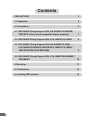
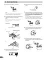
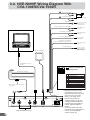
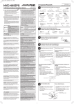
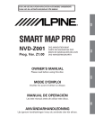
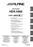
PRECAUTIONS
■ GUIDE FOR INSTALLATION AND CONNECTIONS
FOR AUTHORIZED ALPINE DEALERS
• Please read this GUIDE FOR INSTALLATION
AND CONNECTIONS FOR AUTHORIZED
ALPINE DEALERS and the OWNER’S MANUAL
thoroughly to familiarize yourself with each control
and function. We at ALPINE hope that your new
NVE-N099P will give you many years of
enjoyment.
In case of problems when installing your unit, please
contact your authorized ALPINE dealer.
Points to Observe for Safe Usage
• For safe operation of this system, please read this
manual carefully. We cannot be responsible for
problems resulting from failure to observe the
instructions in this manual.
• Pictorial displays are used to point out safety tips
to prevent harm to yourself or others and property
damage. Here is what these pictorial displays
mean. Knowing them is important to understand
this manual.
• Meaning of displays
This symbol means important
Warning instructions. Failure to heed them
can result in serious injury or
death.
This symbol means important
instructions. Failure to heed them
Caution can result in injury or material
property damage.
Warning
DO NOT DISASSEMBLE OR ALTER.
Doing so may result in an accident, fire or electric
shock.
KEEP SMALL OBJECTS SUCH AS BOLTS OR
SCREWS OUT OF THE REACH OF CHILDREN.
Swallowing them may result in serious injury. If swallowed, consult a physician immediately.
USE THE CORRECT AMPERE RATING WHEN
REPLACING FUSES.
Failure to do so may result in fire or electric shock.
USE ONLY IN CARS WITH A 12 VOLT NEGATIVE
GROUND.
(Check with your dealer if you are not sure.) Failure to
do so may result in fire, etc.
2
BEFORE WIRING, DISCONNECT THE CABLE FROM
THE NEGATIVE BATTERY TERMINAL.
Failure to do so may result in electric shock or injury
due to electrical shorts.
DO NOT ALLOW CABLES TO BECOME ENTANGLED IN SURROUNDING OBJECTS.
Arrange wiring and cables in compliance with the
manual to prevent obstructions when driving. Cables or
wiring that obstruct or hang up on places such as the
steering wheel, shift lever, brake pedals, etc. can be
extremely hazardous.
DO NOT SPLICE INTO ELECTRICAL CABLES.
Never cut away cable insulation to supply power to
other equipment. Doing so will exceed the current
carrying capacity of the wire and result in fire or electric
shock.
DO NOT INSTALL IN LOCATIONS WHICH MIGHT
HINDER VEHICLE OPERATION, SUCH AS THE
STEERING WHEEL OR SHIFT LEVER.
Doing so may obstruct forward vision or hamper
movement etc. and results in serious accident.
DO NOT DAMAGE PIPE OR WIRING WHEN
DRILLING HOLES.
When drilling holes in the chassis for installation, take
precautions so as not to contact, damage or obstruct
pipes, fuel lines, tanks or electrical wiring. Failure to
take such precautions may result in fire.
DO NOT USE BOLTS OR NUTS IN THE BRAKE OR
STEERING SYSTEMS TO MAKE GROUND
CONNECTIONS.
Bolts or nuts used for the brake or steering systems (or
any other safety-related system), or tanks should
NEVER be used for installations or ground connections.
Using such parts could disable control of the vehicle
and cause fire etc.
DO NOT INSTALL THE MONITOR NEAR THE
PASSENGER SEAT AIR BAG.
If the unit is not installed correctly the air bag may not
function correctly and when triggered the air bag may
cause the monitor to spring upwards causing an
accident and injuries.
MAKE THE CORRECT CONNECTIONS.
Failure to make the proper connections may result in
fire or product damage.
Caution
ARRANGE THE WIRING SO IT IS NOT CRIMPED OR
PINCHED BY A SHARP METAL EDGE.
Route the cables and wiring away from moving parts
(like the seat rails) or sharp or pointed edges. This will
prevent crimping and damage to the wiring. If wiring
passes through a hole in metal, use a rubber grommet
to prevent the wire’s insulation from being cut by the
metal edge of the hole.
HAVE THE WIRING AND INSTALLATION DONE BY
EXPERTS.
The wiring and installation of this unit requires special
technical skill and experience. To ensure safety, always
contact the dealer where you purchased this product to
have the work done.
USE SPECIFIED ACCESSORY PARTS AND INSTALL
THEM SECURELY.
Be sure to use only the specified accessory parts. Use
of other than designated parts may damage this unit
internally or may not securely install the unit in place.
This may cause parts to become loose resulting in
hazards or product failure.
DO NOT INSTALL IN LOCATIONS WITH HIGH
MOISTURE OR DUST.
Avoid installing the unit in locations with high incidence
of moisture or dust. Moisture or dust that penetrates into
this unit may result in product failure.
Precautions
IMPORTANT
Please record the serial number of your unit in the
space provided on the back cover of Owner’s
Manual and keep it as a permanent record. The
serial number plate is located on the bottom of the
unit.
• For installation of the main unit, avoid areas with a
high incidence of dust or moisture. Installing the
unit in such locations may result in contamination
of the DVD ROM making it unreadable.
• Do not install the navigation system near a CD
player that may interfere with GPS signal
reception.
• The optimum locations for installing the GPS aerial
are:
– on the dashboard where no metal piece (such
as the defogger wire or aerial wire) is located on
the windshield.
– where no metal cover is located.
• Route the Speed Pulse Sensor cable away from
the audio cables in order to avoid picking up
noises.
3
Contents
4
PRECAUTIONS
2
1. Preparation
5
2. Connections
6
3-1. NVE-N099P Wiring Diagram With IVA-D300R/IVA-D300RB/
TME-M770 (Touch panel-compatible Alpine products)
7
3-2. NVE-N099P Wiring Diagram With CVA-1004R/CVA-1003R
8
3-3. NVE-N099P Wiring Diagram With IVA-D900R/IVX-C806/
IVA-C800R/IVX-M706/IVA-M700R/CVA-1006R/CVA-1005R/
TME-M760/TME-M750/TME-M580
9
3-4. NVE-N099P Wiring Diagram With CVA-1000R/TME-M006SP/
TME-M005P
10
4. Mounting
11
5. Confirmation
12
6. Installing TMC antenna
13
1. Preparation
1
Check accessory parts.
GPS aerial
(5 m)
Aerial
mounting plate
(2.5 m)
Power cables
7 Flanged hex
nut (M6)
Remote
control
Battery (AAA)
4 Hex bolt (M6 × 50)
×4
5 Flanged self-tapping
screw (M5 × 15)
×4
×4
8 Wing nut (M6) 9 Velcro fastener ! Velcro tape
×4
Remote control
holder
×2
3 Screw with double
washer (M4 × 8)
×2
One each for left and right
×4
×2
Solderless
connector
Extension cables
2 Floor base
6 Spring
washer (M6)
Parking brake
aux. cord
13P RGB extension cable (6 m)
(4.5 m)
1 Bracket
×3
Cable clamp
" Self-tapping screw
(M3 × 12)
×2
×4
×4
Note:
• For further details about accessory parts for the TMC antenna, refer to “6. Installing TMC antenna”(page 13).
2
Prepare tools and mounting information.
Screwdriver
Spanner
3
4
5
Electrical tape
Pliers
Mounting the aerial inside the vehicle.
1. Clean the mounting location.
2. Put on the aerial mounting plate.
3. Mount the aerial.
Pencil and eraser
Park the vehicle in a safe and level location.
Aerial
Notes:
• Mount the aerial on a flat plane of the dash board or
rear tray.
• Some thermal reflection type or thermal absorption
type glass may interrupt high frequency waves. If
reception is poor with the aerial installed inside the
car, try to mount the aerial outside the car.
Apply the brake and remove the ignition key.
Mount the aerial on the roof.
Clean dust and oil at the mounting location and
mount the aerial.
Aerial
Notes:
• The magnet of the aerial is very strong. Proceed
cautiously to prevent any damage to the vehicle’s body.
Keep the magnet away from articles susceptible to
magnetic fields such as credit cards, watches, etc.
• Do not paint the aerial. Reception sensitivity may be
decreased.
6
Routing the aerial cable.
1. Route the cable using the provided cable clamps
to take up the cable’s slack.
2. Use the waterproof pad when running the cable
under the vehicle’s rubber gasket.
3. Attach the cable at several points using the
remaining cable clamps.
Water
proof pad
Cable clamp
5
2. Connections
1
Disconnect the battery (–) terminal.
Note:
Some vehicles contain a vehicle control computer etc. in
this case, contents of the computer memory may be
erased when the battery (–) lead is disconnected.
2
4
5
Cut terminal leads as required, and attach the
solderless connectors to the leads.
Note:
For leads which need branching to the speed sensor,
dimmer, parking brake, etc., use the solderless
connectors.
Wrap electrical tape around end of leads not
used.
Connect the battery (–) terminal and turn the
ignition key to the ACC or ON position. Check
to see if operation can be performed properly.
(Is the power turned on? Is the illumination
turned on?)
You can check the language selection menu with
the monitor. (Refer to the Owner’s Manual for
details.) Go to step 6 after checking is completed.
ON
Preparation
6
Navigation side lead
1
Turn the ignition key to the OFF position to
turn off the power after completion of the
check.
Solderless connector
(supplied with the unit)
Vehicle lead
OFF
Navigation
side lead
Stopper
2
Pliers
3
6
Connect the power lead to this unit.
Insert until a click sound is heard.
7
Pull out the ignition key and remove the
battery terminal (–) again to begin installation
procedure.
3-1. NVE-N099P Wiring Diagram With IVA-D300R/IVA-D300RB/
TME-M770 (Touch panel-compatible Alpine products)
Battery Lead (Yellow)
(5A)
BATTERY
ACC (Ignition) (Red)
To the Acc power lead
(5A)
Ground (Black)
Dimmer In (Illumination) (+) (White/Blue)
Parking Brake (Yellow/Blue)
Reverse (+) (Orange/White)
To the Illumination
signal line
To the parking brake
signal line
To reverse lights
(+12V signal)
Speed Sensor (Green/White)*1
Connect to VSS (Digital or Analog 0V - 3V)
SUBW.
PRE IN/OUT
Connect to a metal
part of classis
body with screw
To the vehicle speed
pulse line
REAR
L
R
FRONT
POWER SUPPLY
Ai-NET
REMOTE IN / OUT
Mute (Pink/Skyblue)
EXT.OUT
NAVIGATION IN
DISPLAY OUT
AV.SELECTOR
GPS Aerial (Included)
Use this to connect
a device having the
IN-INT function (-)
output for Audio Mute
CAMERA IN
AUX OUT
VIDEO
(MONO)
L
AUDIO
R
AUX IN
RADIO ANTENNA IN
13P RGB Extension Cable Included
A
1 2 3 4 5
6 7 8 9 10
TMC Antenna (Included)*2
1
2
3
4
5
6
7
8
9
10
Attach to a bare metal chassis part of
your vehicle.
A
5
1
10
ANT.
EX-1
EX-2
System expansion ports
Power Connector
Pin Configuration
DISP.
GPS
6
POWER
Ground (Black)
ACC (Ignition) (Red)
Mute (Pink/Skyblue)
Open
Open
Battery (Yellow)
Dimmer In (Illumination) (White/Blue)
Speed Sensor (Green/White)
Parking Brake (Yellow/Blue)
Reverse (Orange/White)
*1 Improper connection of the
speed pulse line may cause
important safety features of the
vehicle to fail (such as the
brakes or air bags). Such
failures may result in an
accident and loss of life. We
strongly recommend that the
installation be performed by a
trained, authorized Alpine
dealer.
*2 For further details about the
installation of the TMC antenna,
refer to “6. Installing TMC
antenna.”(page 13)
7
3-2. NVE-N099P Wiring Diagram With
CVA-1004R/CVA-1003R
Battery Lead (Yellow)
(5A)
BATTERY
ACC (Ignition) (Red)
To the Acc power lead
(5A)
Ground (Black)
Dimmer In (Illumination) (+) (White/Blue)
Parking Brake (Yellow/Blue)
Reverse (+) (Orange/White)
Speed Sensor (Green/White)*1
Connect to VSS (Digital or Analog 0V - 3V)
Mute (Pink/Skyblue)
GPS Aerial (Included)
Connect to a metal
part of classis
body with screw
To the Illumination
signal line
To the parking brake
signal line
To reverse lights
(+12V signal)
To the vehicle speed
pulse line
Use this to connect
a device having the
IN-INT function (-)
output for Audio Mute
13P RGB Extension Cable
Included
A
Power Connector Pin
Configuration
1
2
3
4
5
6
7
8
9
10
Ground (Black)
ACC (Ignition) (Red)
Mute (Pink/Skyblue)
Open
Open
Battery (Yellow)
Dimmer In (Illumination) (White/Blue)
Speed Sensor (Green/White)
Parking Brake (Yellow/Blue)
Reverse (Orange/White)
1 2 3 4 5
6 7 8 9 10
TMC Antenna (Included)*2
Attach to a bare metal chassis part of
your vehicle.
A
5
1
10
ANT.
EX-1
EX-2
System expansion ports
8
DISP.
GPS
6
POWER
*1 Improper connection of the
speed pulse line may cause
important safety features of the
vehicle to fail (such as the
brakes or air bags). Such
failures may result in an
accident and loss of life. We
strongly recommend that the
installation be performed by a
trained, authorized Alpine
dealer.
*2 For further details about the
installation of the TMC antenna,
refer to “6. Installing TMC
antenna.”(page 13)
3-3. NVE-N099P Wiring Diagram With IVA-D900R/IVX-C806/
IVA-C800R/IVX-M706/IVA-M700R/CVA-1006R/CVA-1005R/
TME-M760/TME-M750/TME-M580
Battery Lead (Yellow)
(5A)
BATTERY
ACC (Ignition) (Red)
To the Acc power lead
(5A)
Ground (Black)
Dimmer In (Illumination) (+) (White/Blue)
Parking Brake (Yellow/Blue)
Reverse (+) (Orange/White)
REAR
To the parking brake
signal line
To reverse lights
(+12V signal)
To the vehicle speed
pulse line
R
L
FRONT
POWER SUPPLY
To the Illumination
signal line
Speed Sensor (Green/White)*
Connect to VSS (Digital or Analog 0V - 3V)
SUB W.
PREOUT
Connect to a metal
part of classis
body with screw
Ai-NET
REMOTE IN/OUT
VIDEO
L
AUX OUT
NAVIGATION IN
Mute (Pink/Skyblue)
AUDIO
1
2
R
DISPLAY OUT
VIDEO
AUX IN 1/2
(MONO)
L
AUDIO
1
GPS Aerial (Included)
3
2
R
Use this to connect
a device having the
IN-INT function (-)
output for Audio Mute
CAMERA IN
VIDEO
(MONO)
L
AUX IN 3
AUDIO
R
RADIO ANTENNA IN
13P RGB Extension Cable Included
A
1 2 3 4 5
6 7 8 9 10
TMC Antenna (Included)*2
1
2
3
4
5
6
7
8
9
10
Attach to a bare metal chassis part of
your vehicle.
A
5
1
10
ANT.
EX-1
EX-2
System expansion ports
Power Connector
Pin Configuration
DISP.
GPS
6
POWER
Ground (Black)
ACC (Ignition) (Red)
Mute (Pink/Skyblue)
Open
Open
Battery (Yellow)
Dimmer In (Illumination) (White/Blue)
Speed Sensor (Green/White)
Parking Brake (Yellow/Blue)
Reverse (Orange/White)
*1 Improper connection of the
speed pulse line may cause
important safety features of the
vehicle to fail (such as the
brakes or air bags). Such
failures may result in an
accident and loss of life. We
strongly recommend that the
installation be performed by a
trained, authorized Alpine
dealer.
*2 For further details about the
installation of the TMC antenna,
refer to “6. Installing TMC
antenna.”(page 13)
9
3-4. NVE-N099P Wiring Diagram With CVA-1000R/
TME-M006SP/TME-M005P
Blue
(Modulator Control)
Battery Lead (Yellow)
Not Connected
White/Brown
(Remote Output)
(White/Brown)*3
(White/Brown)*3
(White/Green)
(White/Green)
(5A)
BATTERY
ACC (Ignition) (Red)
White/Green
(Guide Control Input)
To the Acc power lead
(5A)
Yellow/Red
(Display Control Input)
(Yellow/Red)
Yellow/Blue
(Parking Brake Input)
Extension Cables
Included
(Yellow/Red)
Ground (Black)
Connect to a metal
part of classis
body with screw
Dimmer In (Illumination) (+) (White/Blue)
To the Illumination
signal line
White/Blue
(Dimmer)
Parking Brake (Yellow/Blue)
Red
(Ignition)
Yellow
(Battery)
To the parking brake
signal line
Reverse (+) (Orange/White)
Speed Sensor (Green/White)*
Connect to VSS (Digital or Analog 0V - 3V)
Black
(Ground)
To reverse lights
(+12V signal)
1
To the vehicle speed
pulse line
TFT COLOR LCD
Mute (Pink/Skyblue)
GPS Aerial (Included)
Use this to connect
a device having the
IN-INT function (-)
output for Audio Mute
SYSTEM CONTROL
MONITOR / RECEIVER 35Wx4 CVA-1000R
VOLUME
V.SEL
SET UP
SOURCE
FUNC
MUTE
RDS
EON
A
POWER SUPPLY
Ai-NET
1 2 3 4 5
DISPLAY OUTPUT
Power Connector
Pin Configuration
6 7 8 9 10
VIDEO OUTPUT
(Yellow)
(Yellow)
AUX1
1
2
3
4
5
6
7
8
9
10
AUX1
(White)
(White)
SYSTEM CONTROL
MONITOR / RECEIVER CVA-1000R
TMC Antenna (Included)*2
Attach to a bare metal chassis
part of your vehicle.
Optional KCE-030N
RCA to 13-Pin DIN
Adaptor
A
5
1
10
ANT.
EX-1
EX-2
System expansion ports
10
DISP.
GPS
6
POWER
Ground (Black)
ACC (Ignition) (Red)
Mute (Pink/Skyblue)
Open
Open
Battery (Yellow)
Dimmer In (Illumination) (White/Blue)
Speed Sensor (Green/White)
Parking Brake (Yellow/Blue)
Reverse (Orange/White)
*1 Improper connection of the
speed pulse line may cause
important safety features of the
vehicle to fail (such as the
brakes or air bags). Such
failures may result in an
accident and loss of life. We
strongly recommend that the
installation be performed by a
trained, authorized Alpine
dealer.
*2 For further details about the
installation of the TMC antenna,
refer to “6. Installing TMC
antenna.”(page 13)
*3 When the TME-M006SP/TMEM005P is connected, this lead is
not used.
4. Mounting
Note:
The main unit must be mounted within ±5 degrees of the
horizontal plane, left to right, and 30 degrees of the
horizontal plane, back to front.
2
Attach the unit on the rear tray.
Attach the unit securely with hex bolts (M6×50)
4, flanged hex nuts (M6) 7, spring washers
(M6) 6, and wing nuts (M6) 8.
Continued to step 5 "Securing leads, etc."
Less than 30°
4
a When mounting using Velcro fastener
1
2
Place Velcro fasteners.
Place two pieces of Velcro fasteners onto the
mounting surface. The rough side should be
facing the navigation unit.
7
(Bottom
side)
Press the Navigation unit onto the Velcro
fastener at the mounting position.
Remove the backing to the adhesive on the
Velcro strips. Press the Navigation unit onto the
mounting location.
Continued to the step 5 "Securing leads, etc."
6
8
a When mounting the unit directly on
the floor
1
Mount the brackets 1 on the unit.
Mount the brackets at both sides of the unit with
screws with double washer (M4×8) 3.
Floor
3
Velcro fasteners
1
Depending on the
locations of the mounting
screw holes, the mounting
brackets (for the left and
right) can be used on
either side.
1
a When mounting on the rear tray
1
Mount the brackets 1 on the unit.
Mount the brackets at both sides of the unit with
screws with double washer (M4×8) 3.
1
3
3
2
Mount the unit on the floor.
Mount the unit on the floor with flanged selftapping screws (M5×15) 5 and spring washers
(M6) 6.
Warning: Do not damage pipe or wiring when
drilling holes.
(Bottom side)
Depending on the
locations of the
mounting screw holes,
the mounting brackets
(for the left and right)
can be used on either
side.
Continued to step 5 "Securing leads, etc."
3
5
6
11
3
a When mounting with floor base
brackets
1
Mount the brackets 1.
Mount the brackets 1 at both sides of the unit
with screws with double washer (M4×8) 3.
Depending on the
locations of the mounting
screw holes, the
mounting brackets (for
the left and right) can be
used on either side.
1
3
Cut the carpet in "x" shape with a cutter and
insert the floor bases 2 from under side of
the carpet.
2
4
Mount the unit on the carpet with spring
washers (M6) 6 and wing nuts (M6) 8.
Continued to step 5 "Securing leads, etc."
1
8
3
2
6
Determine mounting position of the floor
bases 2 for placement under the carpet.
5
8
6
6
Securing leads, etc.
Make sure leads are not pinched by moving parts
such as the seat rail, etc. Also check for damaged from sharp edges or protrusion.
Connect the battery (−) terminal.
2
5. Confirmation
1
Turn on the engine key. Make sure the unit is
operating correctly by referring to the Owner’s Manual.
a Remote control holder mounting method
•
•
ON
If the remote control is in direct sunlight, remove
it from the holder and keep it in the glove box.
When the holder cannot be mounted securely
with double-sided adhesive tape !, mount it by
using screws ".
Reinforcement screws "
2
Remote control
Remote
control
holder
Make sure all factory components such as the
brake lamps, etc. work correctly.
!*
Protective
Paper
Console box, etc.
*
12
Double-sided adhesive tape. (Before attaching
the tape, make sure the mounting location is free
from dust or dirt.)
6. Installing TMC antenna
1
Check accessory parts.
Antenna cable
(3.5 m)
Film Antenna
2
×8
Cable clamp
Work spatula
Ground plate
JASO/ISO
Antenna
Adaptor
Attaching the film antenna to the front window
10 mm or less
;;
;;;;;;;;;;;;;;;;;;;;;;;;;;;;;;;;;;;;;;;;;;;
;;;;;;;;;;;;;;;;;;;;;;;;;;;;;;;;;;;;;;;;;;;
;;;;;;;;;;;;;;;;;;;;;;;;;;;;;;;;;;;;;;;;;;;
;;;;;;;;;;;;;;;;;;;;;;;;;;;;;;;;;;;;;;;;;;;
;;;;;;;;;;;;;;;;;;;;;;;;;;;;;;;;;;;;;;;;;;;
;;;;;;;;;;;;;;;;;;;;;;;;;;;;;;;;;;;;;;;;;;;
;;;;;;;;;;;;;;;;;;;;;;;;;;;;;;;;;;;;;;;;;;;
metallic part
;;;;;;;;;;;;;;;;;;;;;;;;;;;;;;;;;;;;;;;;;;;
;;;;;;;;;;;;;;;;;;;;;;;;;;;;;;;;;;;;;;;;;;;
;;;;;;;;;;;;;;;;;;;;;;;;;;;;;;;;;;;;;;;;;;;
;;;;;;;;;;;;;;;;;;;;;;;;;;;;;;;;;;;;;;;;;;;
;;;;;;;;;;;;;;;;;;;;;;;;;;;;;;;;;;;;;;;;;;;
;;;;;;;;;;;;;;;;;;;;;;;;;;;;;;;;;;;;;;;;;;;
;;;;;;;;;;;;;;;;;;;;;;;;;;;;;;;;;;;;;;;;;;;
1. Clean the window surface to which you wish to
attach the film antenna.
2. Spray the window glass with detergent solution
(approximately 500 ml. water and one or two
drops of synthetic detergent) thoroughly.
3. Remove the clear sheet from the adhesive side
of film antenna, then attach it to the window.
When attaching the film, be sure to break any
trapped air bubbles using the supplied work
spatula. Wipe off the moisture with paper, etc.,
being careful not to move the film antenna.
• Keep the metallic part of the film antenna within 25 mm of
the ceramic line when attaching.
• Do not place the metallic part of film antenna on the
ceramic line.
3
Installing the antenna cable
Power connection
• Attach the power connection to the antenna by
aligning the two protrusions of the case with the 8
mark of the film.
• Remove the clear sheet from the inner-facing side of
film antenna and the moisture protection sheet on the
metallic part of the film antenna.
1
2
3
4
5
To Antenna Receptacle
1 Film Antenna
2 Ground Connector
Connect this lead to a good chassis ground on the vehicle.
Attach the Ground connector to the ground plate after removing
the protective paper.
3 Ground Plate
Remove the protective paper and attach to a bare metal chassis
part of your vehicle. Before attaching, clean the surface.
4 JASO Antenna Plug
5 JASO/ISO Antenna Adaptor (Included)
Notes:
• Be sure to install the antenna cable only after the film has entirely dried.
• Ensure to follow the instructions below to avoid poor reception.
• Fix the Ground connector to a bare metal chassis part of your vehicle securely using the ground plate.
• Install the cable securely after attaching to a bare metal chassis part of your vehicle with the included cable clamps.
• Attach the power connection to the film securely.
13