1
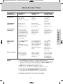
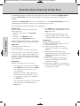
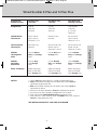
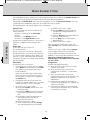
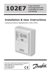
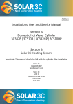
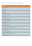
21958 Honeywell Issue 16_11394 Honeywell Issue 14 26/04/2011 09:04 Page FC1
Wiring Guide
Issue 16
21958 Honeywell Issue 16_11394 Honeywell Issue 14 26/04/2011 09:04 Page IFC1
Contents
Section
Title
Introduction
Contact
Page
1
2
Wiring plans
System wiring notes
Sundial S Plan
Sundial S Plan Plus
Sundial Y Plan
Sundial C Plan
Sundial C Plan Plus
Sundial W Plan
Sundial U Plan
Training
Boiler wiring
Programmer wiring
Valve wiring
Sundial RF² wiring
Smartfit
Frost thermostats
Wiring centre
3
4-5
6-7
8-9
10 - 11
12
13
14
15
16
17
18
19
20 - 21
22
23
Fault finding
Wired
Wired
Wired
Wired
24 - 25
26 - 27
28 - 29
30 - 31
Product selection
Energy saving
Product selection
32 - 33
34 - 37
Further information
Website
Training
38
39
Sundial
Sundial
Sundial
Sundial
Y Plan
S Plan and S Plan Plus
C Plan
W Plan
21958 Honeywell Issue 16_11394 Honeywell Issue 14 26/04/2011 09:04 Page 1
Introduction
Domestic energy consumption
24% Hot water
60% Heating
3%
3%
3%
3%
2%
2%
Lighting
Cooking
Consumer electronics
Cold appliances
Other
Wet appliances
Source : BERR
© 2009 Honeywell International Inc. All rights reserved.
A huge amount of energy is used to heat homes. Much of it is either wasted or used inefficiently.
Heating controls help to reduce waste reduce demand and use fuel more sparingly.
Honeywell has been manufacturing heating controls for over 100 years and is the UK leader for
quality, efficiency and reliability.
This book contains wiring advice to assist with installing Honeywell heating controls in a variety of
systems. Always try to upgrade a system to the best efficiency. This would normally be a fully
pumped system with a high efficiency boiler using S, Y or S Plan Plus controls.
All wiring should be carried out by a competent installer or electrician.
These wiring diagrams are for guidance only and at the time of printing represent the latest information available to
us from other manufacturers. Honeywell reserve the right at any time and without notice to change any product,
specification or any other information contained in this publication and cannot accept any responsibility for loss or
damage arising out of any errors that may inadvertently be contained herein.
Whilst Honeywell takes all reasonably practical steps to design and manufacture its products to comply with the
requirements of the Health and Safety at Work Act 1974, all products must be properly used and purchasers are
reminded that their obligations under the Act are to ensure that the installation and operation of such products at a
place of work should be safe and without risk to them.
1
21958 Honeywell Issue 16_11394 Honeywell Issue 14 26/04/2011 09:04 Page 2
Contact
Sales Enquiries
Tel: 01344 656172
Email: [email protected]
Installer Training
Tel: 01344 656352
Email: [email protected]
Web: www.honeywelluk.com (see Training page under Support Services menu)
Product Literature
Tel: 0800 521121
Email: [email protected]
Web: www.honeywelluk.com (see Downloads menu)
Technical Support
Tel: 08457 678999
Email: [email protected]
Web: www.honeywelluk.com (see FAQ section)
To help in dealing with your technical support enquiry efficiently (whether via phone or email) please
supply the part code, product name and date code. Please only call our technical support
number if you are an installer. End user support literature such as user guides and brochures is
available for download on our website.
All phone lines are open Monday to Thursday 9am to 5pm and Friday 9am to 4pm. Closed all bank
holidays.
2
21958 Honeywell Issue 16_11394 Honeywell Issue 14 26/04/2011 09:04 Page 3
System wiring notes
Wiring plans
The Sundial Plan diagrams in this guide are designed
for ease of wiring to a 10 way junction box (Honeywell
part number 42002116-001). Where three plans are
illustrated there is one for wired, wireless and wireless
enabled controls.
Connect the controls, pump, boiler and 230 Volt fused
supply to the junction box terminals indicated by the
arrows in the diagrams next to each control, other
electrical device or circuit. These diagrams should be
read in conjunction with product installation instructions.
A list of boilers can be found on page 16. Boilers with
built in programmers must be wired in accordance with
the manufacturers instructions.
10 way junction box
42002116-001
ALL WIRING MUST BE IN ACCORDANCE WITH IEE & BUILDING REGULATIONS AND IN
SOME CASES, NOTIFIABLE TO BUILDING CONTROL.
A list of programmers can be found on page 17. The room thermostat and programmer are for use
with fixed wiring only; the cylinder thermostat may be used with fixed wiring or flexible cable; the
motorised valves are supplied fitted with a one metre length of heat resistant cable.
A switch (having contact separation of at least 3mm in all poles) must be incorporated in the fixed
wiring as a means of disconnecting the mains supply.
The heating system must be appropriately fused for gas appliances. The diagrams refer only to 3
amp fuses for gas appliances throughout. Use a 5 amp fuse for oil where appropriate. The T6360B
room thermostat, L641A cylinder thermostat and Honeywell range of programmers are Class II
(double insulated) devices. Earth terminals, where provided, are for earth parking purposes only. All
earth conductors inside the programmer and room thermostat must be appropriately sleeved. The
zone valves are Class I devices and must be connected to a suitable earth.
3
21958 Honeywell Issue 16_11394 Honeywell Issue 14 26/04/2011 09:04 Page 4
Sundial S Plan
A
Fully Pumped System only
Brown
5
1
Blue
2
2
Grey
5
**
A
5
B
4
DT90E
Room
Thermostat
**
1
3
5
2
2
T6360B
Room
Thermostat
or
B
1
3
Orange
10
4
Green/
Yellow
3
5
1
4
CM901
CM907
Wireless
Thermostats
Available
or
6
V4043H
Heating
Valve
7
8
9
1
C
2
Brown
8
Blue
2
Grey
1
6
Orange
10
Not Used
Green/
Yellow
3
8
L641A
Cylinder
Thermostat
10
V4043H
Hot Water
Valve
L
1
N
2
E
3
10 Way junction
box. Honeywell
part no:
42002116-001
230 Volt
Mains Input
For list of central heating boilers to attach to this circuit - see page 16.
For list of programmers to attach to this circuit - see page 17.
When circuit is wired as above: Completed wiring will be as line drawing below.
Wired
NOTE:
GREY
BLUE
MOTOR
**
L641A
CYLINDER
STAT.
2 1 3
1
C
ORANGE
T6360B
ROOM STAT.
ORANGE
G/YELLOW
L N E
BROWN
3. For wiring other room thermostats
see above**.
230V
50Hz
3A RATED
V4043H
ZONE VALVE
HW
MOTOR
BROWN
G/YELLOW
2. If using the V4043H1080 (1” BSP) or
V4043H1106 (28mm), the white wire
must be electrically isolated.
GREY
V4043H
ZONE VALVE
HTG
1. It is recommended that either the 10
way junction box or Sundial Wiring Centre
should be used to ensure first time, fault
free wiring.
BLUE
Wiring plans
If using a 6 wire 28mm or 1" BSP V4043H on either circuit, the white wire is not needed and must
be made electrically safe.
Pump overrun
1
7
8
9
2
3
4
5
6
7
8
9
10
10
N L
N EL
PUMP
SL
PL
L
E
N
BOILER
N EL
ST9400A/C
HW HTG
PUMP
L
E
N
BOILER
For Frost Protection information - see page 22
4
21958 Honeywell Issue 16_11394 Honeywell Issue 14 26/04/2011 09:04 Page 5
Sundial S Plan
Wireless room thermostat
BLUE
230V
50Hz
3A RATED
V4043H
ZONE VALVE
HW
BLUE
MOTOR
BROWN
G/YELLOW
GREY
2. If using the V4043H1080 (1” BSP) or
V4043H1106 (28mm), the white wire
must be electrically isolated.
GREY
V4043H
ZONE VALVE
HTG
1. It is recommended that either the 10
way junction box or Sundial Wiring Centre
should be used to ensure first time, fault
free wiring.
MOTOR
L641A
L
N A B
CYLINDER
STAT.
1
C
ORANGE
RECEIVER
BDR91
BROWN
L N E
ORANGE
G/YELLOW
3. The same terminal numbers are used
on the receiver for both the DT92E and
Y6630D Wireless Room Thermostats.
Pump overrun
1
7
8
9
2
3
4
5
6
7
8
9
10
10
N L
N EL
DT92E
WIRELESS ROOM
THERMOSTAT
SL
PL
L
E
N
N EL
PUMP
PUMP
HW HTG
ST9400A/C
L
E
N
BOILER
BOILER
For Frost Protection information - see page 22
Wireless enabled room thermostat (Sundial RF² Pack 2)
NOTE:
V4043H
ZONE VALVE
HTG
L641A
CYLINDER
STAT.
1
C
ORANGE
G/YELLOW
ORANGE
L N E
3. If replacing an old wired
thermostat remove cabling and
add a link between terminals 4
and 5 as shown.
MOTOR
BROWN
G/YELLOW
230V
50Hz
3A RATED
MOTOR
BROWN
GREY
2. If using the V4043H1080 (1”
BSP) or V4043H1106 (28mm),
the white wire must be
electrically isolated.
V4043H
ZONE VALVE
HW
BLUE
GREY
DT92E
WIRELESS ROOM
THERMOSTAT
BLUE
1. It is recommended that the
10 way junction box should be
used to ensure first time, fault
free wiring.
LINK
Pump overrun
HEATING
R
HOT WATE
EXTRA
1
HOUR
2
3
4
5
6
7
8
9
10
OVERRIDE
EXTRA
7
8
N EL
PUMP
9
10
HOUR
OVERRIDE
SL
PL
L
E
N
BOILER
CONT
ONCE
AUTO
OFF
CONT
ONCE
AUTO
OFF
ST9420
PROGRAMMER
L
N
E
3
4
N EL
For Frost Protection information - see page 22
5
PUMP
L
E
N
BOILER
Wiring plans
NOTE:
21958 Honeywell Issue 16_11394 Honeywell Issue 14 26/04/2011 09:04 Page 6
Sundial S Plan Plus
Fully Pumped System only
**
A
5
B
4
DT90E
Room
Thermostat
or
1
** 4
3
5
2
2
Brown
5
1
Blue
2
2
Grey
1
3
Orange
10
Green/
Yellow
3
T6360B
Room
Thermostat
4
10 Way junction
box. Honeywell
part no:
42002116-001
V4043H
Heating
Valve 1
5
6
7
8
9
Brown
8
Blue
2
Grey
1
1
C
6
Not
Used
8
2
L641A
Cylinder
Thermostat
Orange
A
7
Blue
2
Grey
1
B
1
Orange
10
Green/
Yellow
Brown
7
CM901
CM907
3
10
10
Green/
Yellow
Wireless
Thermostats
Available
V4043H
Hot Water
Valve
3
V4043H
Heating
Valve 2
L
1
N
2
E
3
230 Volt
Mains Input
For list of central heating boilers to attach to this circuit - see page 16.
For list of programmers to attach to this circuit - see page 17.
When circuit is wired as above: Completed wiring will be as line drawing below.
Wired
V4043H
ZONE VALVE
HTG1
BLUE
230V
50Hz
3A RATED
CM900 SERIES
PROGRAMMABLE
STAT.
L641A
T6360B
ROOM STAT.
**
CYLINDER
STAT.
2 1 3
1
C
ORANGE
L N E
A
1
8
9
2
3
4
5
6
7
8
9
10
10
N L
NEL
N EL
PUMP
SL
PL
L
E
N
BOILER
ST9400A/C
PUMP
HW HTG
L
E
N
BOILER
For Frost Protection information - see page 22
6
B
ORANGE
G/YELLOW
G/YELLOW
BLUE
MOTOR
Pump overrun
7
V4043H
ZONE VALVE
HTG2
MOTOR
ORANGE
3. For wiring other room
thermostats see above**.
BLUE
MOTOR
BROWN
G/YELLOW
2. If using the V4043H1080
(1” BSP) or V4043H1106
(28mm), the white wire must
be electrically isolated.
V4043H
ZONE VALVE
HW
BROWN
1. It is recommended that the
10 way junction box should
be used to ensure first time,
fault free wiring.
BROWN
NOTE:
GREY
GREY
GREY
Wiring plans
If using a 6 wire 28mm or 1" BSP V4043H on either circuit, the white wire is not needed and must
be made electrically safe.
21958 Honeywell Issue 16_11394 Honeywell Issue 14 26/04/2011 09:04 Page 7
Sundial S Plan Plus
Wireless room thermostat
V4043H
ZONE VALVE
HTG1
BLUE
G/YELLOW
CM900 SERIES
PROGRAMMABLE
STAT.
L641A
RECEIVER
BDR91
CYLINDER
STAT.
L
N A B
2
3
4
1
5
6
C
7
8
ORANGE
L N E
1
9
A
7
NEL
PUMP
HW HTG
7
8
9
10
L
E
N
BOILER
For Frost Protection information - see page 22
B
Pump overrun
10
N L
DT92E
WIRELESS ROOM
THERMOSTAT
ORANGE
BROWN
G/YELLOW
BLUE
MOTOR
230V
50Hz
3A RATED
ST9400A/C
V4043H
ZONE VALVE
HTG2
MOTOR
ORANGE
3. The same terminal
numbers are used on the
receiver for both the DT92E
and Y6630D Wireless
Room Thermostats.
BLUE
MOTOR
BROWN
G/YELLOW
2. If using the V4043H1080
(1” BSP) or V4043H1106
(28mm), the white wire
must be electrically isolated.
V4043H
ZONE VALVE
HW
BROWN
GREY
GREY
GREY
1. It is recommended that
the 10 way junction box
should be used to ensure
first time, fault free wiring.
N EL
PUMP
SL
PL
L
E
N
BOILER
Wiring plans
NOTE:
21958 Honeywell Issue 16_11394 Honeywell Issue 14 26/04/2011 09:04 Page 8
Sundial Y Plan
Fully Pumped System only
Wiring plans
A
5
**
A
3
5
4
2
2
or
L
1
N
2
E
3
230 Volt
Mains Input
T6360B
Room
Thermostat
C
1
4
5
B
DT90E
Room
Thermostat
**
1
B
or
2
Wireless
Thermostats
Available
4
3
5
6
White
5
Blue
2
Grey
7
8
Orange
8
7
Green/
Yellow
3
1
2
1
CM901
CM907
6
L641A
Cylinder
Thermostat
7
8
9
10
10 Way junction
box. Honeywell
part no:
42002116-001
V4073A
Mid.Pos.
Valve
For list of central heating boilers to attach to this circuit - see page 16.
For list of programmers to attach to this circuit - see page 17.
When circuit is wired as above: Completed wiring will be as line drawing below.
Wired
2. For wiring other room
thermostats see above**.
ORANGE
WHITE
230V
50Hz
3A RATED
GREY
V4073A
G/YELLOW
1. It is recommended that the 10
way junction box should be used to
ensure first time, fault free wiring.
BLUE
NOTE:
L641A
CYLINDER
STAT.
**
L N E
T6360B
1
ROOM STAT.
2 1 3
1
2
3
4
MID POSITION
ZONE VALVE
C 2
5
6
7
8
9
10
Pump overrun
C
7
8
9
10
ST9400A/C
HW OFF
HW ON
HTG
LINK 8 TO 10
L
E
N
N L
N EL
PUMP
BOILER
SL
PL
L
E
N
BOILER
NEL
PUMP
For Frost Protection information - see page 22
8
21958 Honeywell Issue 16_11394 Honeywell Issue 14 26/04/2011 09:04 Page 9
Sundial Y Plan
Wireless room thermostat
L641A
L N E
CYLINDER
STAT.
RECEIVER
BDR91
1
L
N A B
DT92E
WIRELESS ROOM
THERMOSTAT
1
2
3
4
MID POSITION
ZONE VALVE
ORANGE
GREY
WHITE
230V
50Hz
3A RATED
2. The same terminal numbers are used on
the receiver for both the DT92E and
Y6630D Wireless Room Thermostats.
V4073A
G/YELLOW
BLUE
1. It is recommended that the 10 way
junction box should be used to ensure first
time, fault free wiring.
Wiring plans
NOTE:
C 2
5
6
7
8
9
10
Pump overrun
LINK 8 TO 10
7
8
9
10
ST9400A/C
HW OFF
HW ON
HTG
C
L
E
N
N L
BOILER
SL
PL
L
E
N
N EL
PUMP
NEL
PUMP
For Frost Protection information - see page 22
BOILER
Wireless enabled room thermostat (Sundial RF² Pack 2)
NOTE:
ORANGE
WHITE
230V
50Hz
3A RATED
GREY
V4073A
G/YELLOW
BLUE
It is recommended that the 10 way junction
box should be used to ensure first time, fault
free wiring.
L641A
MID POSITION
ZONE VALVE
CYLINDER
STAT.
L N E
1
C 2
DT92E
WIRELESS ROOM
THERMOSTAT
1
R
HOT WATE
C
EXTRA
3
4
5
6
7
8
9
10
HOUR
OVERRIDE
EXTRA
LINK 8 TO 10
7
2
HEATING
Pump overrun
8
N EL
PUMP
9
HOUR
OVERRIDE
CONT
ONCE
AUTO
OFF
CONT
ONCE
AUTO
OFF
10
SL
PL
L
E
N
BOILER
ST9420
PROGRAMMER
L
N
E
1
3
4
L
E
N
BOILER
NEL
PUMP
For Frost Protection information - see page 22
9
21958 Honeywell Issue 16_11394 Honeywell Issue 14 26/04/2011 09:05 Page 10
Sundial C Plan
A
5
**
A
**
1
3
5
4
2
2
or
T6360B
Room
Thermostat
L
1
N
2
E
3
230 Volt
Mains Input
or
C
1
1
4
5
B
DT90E
Room
Thermostat
B
2
CM901
CM907
3
4
Wireless
Thermostats
Available
5
1
6
Not Used
2
8
L641A
Cylinder
Thermostat
Brown
8
6
Blue
2
7
Grey
1
8
Orange
10
9
Green/
Yellow
White
3
10
9
Hot Water
Valve
10 Way junction
box. Honeywell
part no:
42002116-001
For list of central heating boilers to attach to this circuit - see page 16.
For list of programmers to attach to this circuit - see page 17.
When circuit is wired as above: Completed wiring will be as line drawing below.
Wired
NOTE:
V4043H
28mm
ZONE VALVE
1. It is recommended that the 10
way junction box should be used to
ensure first time, fault free wiring.
BLUE
2. For wiring other room thermostats
see above**.
GREY
MOTOR
G/YELLOW
230V
50Hz
3A RATED
T6360B
ORANGE
L641A
L N E
CYLINDER
STAT.
ROOM STAT.
2 1 3
1
C
BROWN
Wiring plans
Gravity Hot Water, Pumped Central Heating
Link terminals 5 - 9 in the 10 way junction box.
WHITE
LINK
1
2
3
4
5
6
7
8
9
10
N L
NEL
ST9400A/C
HW HTG
PUMP
L
E
N
BOILER
For Frost Protection information - see page 22
10
L
I
N
K
21958 Honeywell Issue 16_11394 Honeywell Issue 14 26/04/2011 09:05 Page 11
Sundial C Plan
Wireless room thermostat
V4043H
28mm
ZONE VALVE
BLUE
2. The same terminal numbers are used on
the receiver for both the DT92E and
Y6630D wireless room thermostats.
GREY
1. It is recommended that the 10 way
junction box should be used to ensure first
time, fault free wiring.
MOTOR
G/YELLOW
230V
50Hz
3A RATED
L
N A B
1
C
BROWN
CYLINDER
STAT.
RECEIVER
BDR91
DT92E
WIRELESS ROOM
THERMOSTAT
ORANGE
L641A
L N E
WHITE
LINK
1
2
3
4
5
6
7
8
9
10
N L
NEL
ST9400A/C
PUMP
HW HTG
L
E
N
BOILER
For Frost Protection information - see page 22
Wireless enabled room thermostat (Sundial RF² Pack 2)
NOTE:
V4043H
28mm
ZONE VALVE
BLUE
2. The same terminal numbers are used
on the receiver for both the DT92E and
Y6630D Wireless Room Thermostats.
GREY
1. It is recommended that the 10 way
junction box should be used to ensure
first time, fault free wiring.
MOTOR
G/YELLOW
230V
50Hz
3A RATED
2
3
4
5
HEATING
R
EXTRA
CONT
ONCE
AUTO
OFF
CONT
ONCE
AUTO
OFF
6
7
8
9
10
NEL
HOUR
OVERRIDE
HOUR
OVERRIDE
WHITE
LINK
1
HOT WATE
C
BROWN
1
DT92E
WIRELESS ROOM
THERMOSTAT
EXTRA
ORANGE
L641A
CYLINDER
STAT.
L N E
ST9420
PROGRAMMER
L
N
E
3
4
PUMP
L
E
N
BOILER
For Frost Protection information - see page 22
11
Wiring plans
NOTE:
21958 Honeywell Issue 16_11394 Honeywell Issue 14 26/04/2011 09:05 Page 12
Sundial C Plan Plus
Gravity Hot Water, Pumped Central Heating
**
A
5
B
4
DT90E
Room
Thermostat
**
1
or
5
1
Blue
2
2
1
Grey
1
3
Orange
9
4
Green/
Yellow
3
5
4
3
5
2
2
T6360B
Room
Thermostat
Brown
5
B
CM901
CM907
Wireless
Thermostats
Available
or
6
V4043H
Heating
Valve
7
8
9
C
1
6
Not Used
2
8
L641A
Cylinder
Thermostat
Brown
8
Blue
2
Grey
1
Orange
10
Green/
Yellow
White
3
10
9
V4043H Hot
Water Valve
28mm or 1” BSP
L
1
N
2
E
3
10 Way junction
box. Honeywell
part no:
42002116-001
230 Volt
Mains Input
For list of central heating boilers to attach to this circuit - see page 16.
For list of programmers to attach to this circuit - see page 17.
When circuit is wired as above: Completed wiring will be as line drawing below.
Wired
V4043H
22mm
ZONE VALVE
HTG
NOTE:
G/YELLOW
T6360B
ROOM STAT.
2 1 3
L641A
CYLINDER
STAT.
1
2
3
4
5
6
C
7
8
ORANGE
L N E
1
MOTOR
G/YELLOW
ORANGE
230V
50Hz
3A RATED
MOTOR
BROWN
2. For wiring other room
thermostats see above**.
V4043H
28mm
ZONE VALVE
HW
BLUE
BROWN
1. It is recommended that the
10 way junction box should be
used to ensure first time, fault
free wiring.
GREY
GREY
BLUE
Wiring plans
A
WHITE
9
10
N L
NEL
ST9400A/C
HW HTG
For Frost Protection
information - see page 22
PUMP
L
E
N
BOILER
12
21958 Honeywell Issue 16_11394 Honeywell Issue 14 26/04/2011 09:05 Page 13
Sundial W Plan
Fully Pumped System only (hot water priority)
A
**
1
DT90E
Room
Thermostat
** 4
5
3
7
7
2
2
B
T6360B
Room
Thermostat
or
B
1
CM901
CM907
Wireless
Thermostats
Available
or
L
1
1
N
2
2
E
3
3
4
230 Volt
Mains Input
5
6
7
8
Brown
5
9
6
Blue
2
10
5
Green/
Yellow
3
1
C
2
7
L641A
Cylinder
Thermostat
10 Way junction
box. Honeywell
part no:
42002116-001
V4044C
Diverter
Valve
For list of central heating boilers to attach to this circuit - see page 16.
For list of programmers to attach to this circuit - see page 17.
When circuit is wired as above: Completed wiring will be as line drawing below.
Wired
DIVERTER
VALVE
BROWN
230V
50Hz
3A RATED
V4044C
G/YELLOW
1. It is recommended that the 10
way junction box should be used
to ensure first time, fault free
wiring.
BLUE
NOTE:
L641A
CYLINDER
STAT.
L N E
2. For wiring other room
thermostats see above**.
T6360B
1
ROOM STAT.
2 1 3
C 2
Pump overrun
6
7
8
N EL
PUMP
9
10
1
SL
PL
L
E
N
2
3
4
5
6
7
8
9
10
N L
ST9400A/C
HW HTG
L
E
N
BOILER
BOILER
NEL
PUMP
For Frost Protection information - see page 22
13
Wiring plans
7
A
21958 Honeywell Issue 16_11394 Honeywell Issue 14 26/04/2011 09:05 Page 14
Sundial U Plan
Wiring plans
Typical Multi-Manifold Schematic Wiring Diagram Using M100 - BG Actuators
A
B
L
L
BROWN
N
HALL MASTER CONTROL
CM900 SERIES THERMOSTAT
LOUNGE
M100-BG MOTOR
BROWN
BLUE N
KITCHEN
M100-BG MOTOR
BROWN
BLUE N
BLUE
ROOM 2
DT90E
B A
GREY
MOTOR
ORANGE
V4043H
MANIFOLD 1
ZONE VALVE
N
N
ROOM 3
T6360B
2 1 3
N
L
MANIFOLD 1
PUMP
L
L
L
MASTER CONTROL
L BEDROOM 1
N
N
A
B
N
L
BROWN
N
BLUE
TYPICAL
SPST
RELAY
GREY
MOTOR
ORANGE
BDR91
BROWN
BLUE N
MOTOR
B
V4043H
MANIFOLD 2
ZONE VALVE
A
N
BED 2
M100-BG
BED 2
DT90E
N
N
L
L
BROWN
MOTOR
TYPICAL
SPST
RELAY
G/YELLOW
2 1 3
L641A
CYLINDER
STAT.
1
2
3
4
5
6
C
7
8
ORANGE
T6360B
ROOM STAT.
ORANGE
L N E
1
MANIFOLD 2
PUMP
MOTOR
BROWN
G/YELLOW
230V
50Hz
3A RATED
V4043H
ZONE VALVE
DHW
BLUE
GREY
BLUE
GREY
V4043H
ZONE VALVE
HTG
9
10
N L
NEL
HW HTG
TIME
CONTROLLER
PUMP
L
E
N
BOILER
Some earths
omitted for
clarity
Linking Underfloor Heating Manifold(s) to a standard ‘S Plan’ system
14
21958 Honeywell Issue 16_11394 Honeywell Issue 14 26/04/2011 09:05 Page 15
Training
Installer Training courses
Wiring plans
Expand your knowledge of heating and water controls with expert training on our one day Installer
courses, all for £30.
•
•
•
•
•
Hands on wiring
Fault finding
Learn about the latest products
Energy conservation
Part L Building Regulations
•
•
•
•
•
•
Available across UK and Ireland.
Tel: 01344 656352
Email: [email protected]
Web: www.honeywelluk.com
15
Wireless controls
Zoning
Smartfit
Sundial plans
Frost protection
Control selection
21958 Honeywell Issue 16_11394 Honeywell Issue 14 26/04/2011 09:05 Page 16
Boiler Wiring
Wiring plans
Terminal Block
S Plan
S Plan Plus
Y Plan
C Plan
C Plan Plus
W Plan
BOILER
9
9
9
9
9
9
10
10
8
10
10
7
3
3
3
3
3
3
2
2
2
2
2
2
1
1
1
1
1
1
9
9
9
9
9
9
10
10
8
10
10
7
2
2
2
2
2
2
Terminal Block
3
3
3
3
3
3
PL
4
PL
Potterton Osprey 2 CFL
Potterton Prima C
PL
PL
Potterton Profile 40-80eL
PL
L
SL
SL
SL
SL
SL
SL
2
Sw
L
SL
Ls
SL
SL
1
1
L2
Sw
L
SL
Sw
L
Sw
L
E
E
E
E
E
E
E
E
E
N
N
N
N
N
N
N
N
N
L
L
L
L
L
L
E
E
E
E
3
4
E
E
N L L
N
N L
N L 7
2
L
2
L
N L3 L
N L L
E
E
N
N
L
L
E
N
L
L
L
N
N
N
N
N
N
N
N
N
E
E
E
E
E
E
E
E
E
N
N
E
E
8
N
N
N
N
E
E
E
E
E
L
L
N
N
E
E
L
N
E
L
L
L
L
Alpha CB24/28
Baxi Combi 130HE
Baxi Combi 80Eco
Baxi Combi 80 Maxflue
Baxi Combi Instant
Boulter Camray 5 (Oil)
Ferroli Arena
Ferroli Domina
Ferroli Optima
Glow-Worm Compact
Grant Combi MK11
Ideal C80/C95FF
Ideal Response
Potterton Combi 80
Potterton Flowsure+
Potterton Performa
Potterton Puma
Range Powermax
Valliant Turbomax
Worcester CDI
Worcester Greenstar
Worcester Highflow
Terminal Block
SYSTEM
BOILERS
PF SL E
PF SL E
L2 E
L2 E
SL E
PF SL E
Lr E
N
L
N L L
N L3
N L3
N PL
N L L
N L
L
L
N
N
N
N
E
E
E
E
N
E
S Plan
S Plan Plus
Y Plan
C Plan
C Plan plus
W Plan
2
2
2
2
1
1
1
1
1
1
1
1
5
7
5
7
E
E
E
E
E
E
E
E
E
E
4
E
E
E
E
E
E
E
E
E
E
E
N
N
N
N
N
N
N
N
N
N
2
N
N
N
N
N
2
N
N
N
N
N
L
L
L
L
L
L
L
L
L
L
1
L
L
L
L
L
1
L
L
L
L
L
1
3
1
1
1
4
1
4
4
1
13
Bk
R1
3
3
1
3
10
3
Ls
Ls
2
4
2
2
2
5
2
5
5
2
14
R
R2
4
4
2
4
9
4
Lr
Lr
L
10
1
L
Blk
PL Sw
L
E
E
4
E
E
E
N
3
2
N
N
N
L
L
L
L
L
L
L
L
N
N
N
N
N
N
BOILER
9
9
9
9
9
9
10
10
8
10
10
7
3
3
3
3
3
3
2
2
2
2
2
2
PUMP
1
1
1
1
1
1
9
9
9
9
9
9
10
10
8
10
10
7
2
2
2
2
2
2
3
3
3
3
3
3
N
E
CONDENSING
BOILER
Baxi 35/60 & 60/100
Baxi Solo 3 PFL
Boulter Bonus (Oil)
Ferroli Tempra
Glow-Worm Compact 60
Glow-Worm HXI
Grant Multipass (Oil)
Ideal Icos
Outdoor Modules 50/70
Valliant Ecotec
Valliant Thermocompact
OIL BOILERS
Boulter Bonus
Esse 60, 80, 100
Grant Multi Pass 50/70
Potterton Statesman
Rayburn 368K Range
Rayburn Heatranger
3
3
3
3
COMBI
BOILERS
Glow-Worm Energy 60
PL
Glow-Worm Micron FF
Glow-Worm Ultimate 60FF P
Glow-Worm Ultimate 70FF 7
Grant Euroflame 50/70
Grant Multipass 50/70
Ideal Istor
Potterton Kingfisher 50-100 PL
Baxi 100HE
Baxi Barcelona
Ideal Icos
Ideal Isar
Keston Celsius
Potterton Promax
Worcester Greenstar
COMBI
S Plan
S Plan Plus
Y Plan
W Plan
REGULAR
BOILER
Basic Boiler
Baxi 45/4 & 57/4
Baxi Bermuda
Baxi Inset 2-50/4e
Baxi Bermuda Inset 3
Baxi Boston 2
Baxi Solo 2 RS
Ferroli Roma 55FF
Ferroli Sigma
CM901
CM907
STAT
PUMP
E
E
E
E
E
E
16
SL E
PL SL E
E
SL E
Ls E
2 E
1 4
L2 E
1
4
4 E
4 E
N L
N L L
N L
N L
N Lp
N L
2
N L3
3 2
N L
N L
21958 Honeywell Issue 16_11394 Honeywell Issue 14 26/04/2011 09:05 Page 17
Programmer Wiring
Connect onto terminal block numbers
7
4
HW OFF HW ON CH ON
3
2
1
E
N
L
Honeywell ST9400, ST9420, ST9500
1
3
4
E
N
L
Honeywell ST6450, ST6400, ST6300
1
3
4
E
N
L
3
4
E
N
L
Honeywell ST6200
Honeywell ST699B, ST799A, (Link L-5-8)
7
6
3
N
L
Honeywell ST7100
7
8
5
E
N
L
ACL Drayton LS522, LS722, LP112, LP241
1
3
4
E
N
L
Danfoss CP15, CP75, FP15, FP75, MP15, MP75, CP715, FP715
1
3
4
E
N
L
3
4
N
L
Glow-Worm Mastermind
Horstmann C21, C27, C121 & C127
1
3
4
E
N
L
Landis RWB2, RWB9, RWB20, 40, 102, 270
1
3
4
E
N
L
Landis RWB20, RWB200
1
3
4
E
N
L
Landis RWB252, Microgyr
1
3
4
E
N
L
Potterton Miniminder
1
3
4
E
N
L
Potterton EP2000/3000/6000 EP2001/3001 (Link L-5)
1
3
4
E
N
L
Sunvic Select 207
1
3
4
E
N
L
E
Horstmann 425, 525, 527, H21, H27, H121, Tiara, (Link L-2-5)
3
1
4
Randall 922, 972, (Link L-2-5)
1
3
6
Randall 4033 (Link 1-6)
5
N
L
N
L
4
2
E
7
6
Randall 102, 102E, 102E5, 102E7, (Link 3-6)
1
2
E
5
6
Randall 701, 702, (Link L-6-5)
4
2
E
N
L
Sangamo M5, (Link 1-6)
1
8
E
N
L
Sangamo Form 1, (Link 3-6)
1
8
E
N
L
1
4
N
L
3
1
N
L
N
L
Switchmaster Symphony
3
Switchmaster 400, 600, (No connection to terminal 4 on 600)
Switchmaster 805, 900, 905, 9001
4
3
1
Sunvic SP50, SP100, (Link L-3)
1
2
5
E
N
L
Sunvic ET1451, (Link 2-3-6)
8
7
4
E
1
2
Sunvic DHP2201
8
6
3
E
1
2
Towerchron FP, (Link 1-5 / 4-7-9)
8
6
10
N
L
6
10
N
L
Towerchron MP, (Link 1-4 / 6-11)
Danfoss Randall 3020P, 3060
4
2
E
7
6
Danfoss Randall SET2, SET2E, SET3EM, FP975, SET5, (Link L-2-5)
3
1
4
E
N
L
Grasslin Towerchron DP72, QE2
1
3
4
N
L
Myson Microtimer, (Link L-5-8)
7
6
3
N
L
Sunvic SP50, SP100, (Link L-3)
1
3
4
N
L
17
Wiring plans
Programmer Interchange
6
21958 Honeywell Issue 16_11394 Honeywell Issue 14 26/04/2011 09:05 Page 18
Wiring plans
Valve Wiring
Replacement Wiring Guide for the old V4073A1005 to all new V4073A models
The old valve had 6 wires and a relay plugged into one end.
When replacing this old model with the newer model, wire the new valve colour for colour apart from
the Brown wire which is missing from the new valve.
ON SINGLE CHANNEL TIME SWITCHES
Omit Brown wire and reverse C & 1 on the cylinder thermostat.
ON DOUBLE CHANNEL PROGRAMMERS i.e. separate switching outputs for Heating and
Hot Water circuits.
Omit Brown wire and reverse C & 1 on the cylinder thermostat.
1. For programmers capable of selecting heating only: Run extra cable from the Grey wire on
the valve to the HOT WATER OFF terminal on the programmer.
2. For programmers NOT capable of selecting heating only: This extra cable is NOT required
and MUST NOT be included.
EXCEPT:
1. ON RANDALL 4033 PROGRAMMER
Remove wire that connects to cylinder thermostat 1 at JUNCTION BOX end and re-connect to
Orange wire connection of mid-position valve. Disconnect wire at Terminal 1 on programmer, isolate
and make safe. Add link in programmer back plate between Terminals 1 and 6.
NB. If the Randall 4033 has been used as a junction box, any wires going into terminal 1 should be
removed and re-connected into a spare terminal connector (not supplied by Honeywell).
2. ON SANGAMO 410 FORM 1 PROGRAMMER
Follow instructions for Randall 4033, except on programmer base plate, disconnect wire on Terminal
3 and add link between 3 and 6 on baseplate of Programmer.
MOTORISED VALVE INTERCHANGEABILITY GUIDE
E
N
CH
ON
HW
OFF
MODEL
V4073A
GY
BL
OR
WH
GR
ACL
679H340
GY
BL
OR
WH
GR
ACL
679B340
GY
BL
OR
WH
GR
Danfoss/Randall
DVM-3M
GY
BL
OR
WH
GR
Danfoss/Randall
HSA3
GY
BL
OR
BR
GR
Drayton
MODEL
HONEYWELL
Drayton Flowshare
No.
S/L
HW
ON
E
N
S/L Motor PL
V4043H
GY
BL
OR
BR
ACL
679H308-30L1
GY
BL
OR
BR
GR
ACL
679B308-30L1
GY
BL
BK
BR
WH
Danfoss/Randall
DVM-2C
GY
Danfoss/Randall
HP2A
HONEYWELL
2
GY
BL
OR
WH
GR
Landis & Gyr
Grasslin/Tower
MP 22C
GY
BL
OR
WH
GR
Pegler/Sunvic
Landis & Gyr
MAV322
GY
BL
OR
WH
GR
Potterton/Myson
GR
RE
WH
GR
Auto Z
GY
BL
OR
BR
GR
MV2-22C
GY
BL
OR
BR
GR
Sunvic V*203
GY
BL
(White wire - make electrically safe)
Connect Grey wire on V4043H to permanent live.
OR
YE
GR
Switchmaster
Potterton/Myson
PMV3
GY
BL
OR
BR
GR
Tower/Grasslin
Potterton/Myson
MSV322
BL
OR
WH
GR
Sopac
ZV20-EB
BL
RE
WH
GR
WH
WH
ADD LINK
GY = Green/Yellow
YE = Yellow
BK = Black
GR
BL
BR
YE
BR
GY
OR
YE
OR
ZV20-2-EB
Sopac
BL
OR
GR
BL
SZV 1212
GR
GY
OR
GR
BR
BR
SD1701
RE
BR
OR
BR
Pegler/Sunvic
RE
OR
BL
OR
Randall
GR
BL
BL
GY
OR
GR
WH
BL
GY
BL
WH
OR
GY
GR
GR
BL
OR
BL
GY
BR
BR
GY
BL
GY
MIDI
OR
OR
GY
GY
SDV2211
Danfoss Heatshare
BL
BL
HPA2
SD2701
Pegler/Sunvic
Switchmaster
ZAV222
GR
PMV43
Pegler/Sunvic
GY
No.
BL = Blue
BR = Brown
RE = Red
18
OR = Orange
WH = White
GR = Grey
21958 Honeywell Issue 16_11394 Honeywell Issue 14 26/04/2011 09:05 Page 19
Sundial RF2 Wiring
Simply replace the programmer and the thermostat works automatically
Supplier
ACL-Drayton
ACL-Drayton
ACL-Drayton
ACL-Drayton
ACL-Drayton
ACL-Drayton
ACL-Drayton
ACL-Drayton
ACL-Drayton
ACL-Drayton
ACL-Drayton
ACL-Drayton
ACL-Drayton
ACL-Drayton
ACL-Drayton
Barlo
Boss Therm
Boss Therm
British Gas
British Gas
British Gas
Danfoss
Danfoss
Danfoss
Danfoss
Danfoss
Danfoss
Danfoss
Danfoss
Danfoss
Danfoss
Glowworm
Homexpert
Honeywell
Honeywell
Honeywell
Honeywell
Horstmann
Horstmann
Horstmann
Horstmann
Programmer
SM2
LP112
LP241
LP522
LP722
LP241Si
LP522Si
LP722Si
Tempus 3
Tempus 4
Tempus 6
Tempus 7
LS241
LS522
LS722
EPR1
RPF7
RP24
EMP1
EMP2
UP1
CP15
CP75
CP715
CP715Si
FP15
FP75
FP715
FP715Si
MP15
MP75
Mastermind
THR860S
ST6400A
ST6400C
ST9400A
ST9400C
Centaurplus C21
Centaurplus C27
Centaurplus C121
Centaurplus C127
Supplier
Iflow
Landis & Gyr
Landis & Gyr
Landis & Gyr
Landis & Gyr
Landis & Gyr
Landis & Gyr
Landis & Gyr
Landis & Gyr
Landis & Gyr
Landis & Gyr
Landis & Gyr
Landis & Gyr
Landis & Gyr
Landis & Gyr
Landis & Staefa
Landis & Staefa
Microgyr
Microgyr
Microgyr
Microgyr
Microgyr
Microgyr
Microgyr
Microgyr
Microgyr
Microgyr
Microgyr
Potterton
Potterton
Sankey
Siemens
Siemens
Sunvic
Thorn
Wickes
Wickes
Wickes
Wickes
Wickes
Programmer
Iflow PR
RWB40
RWB102
RWB200
RWB200cw
RWB252
RWB252cw
RWB270
RWB1
RWB Mk1
RWB2
RWB2 Mk2
RWB2.9
RWB9
RWB-XP
RWB9
RWB2E
1
102
2
40
200
200cw
252
252cw
270
9
XP
Miniminder
Miniminder E
Sunline
RWB29
RWB270
Select 207
Miniminder
RWB2/6832
RWB200.cw
RWB252.cw
RWB2E.cw
RWB9.cw
This information is based on the backplate supplied with the original programmer.
19
Wiring plans
ST9420 fits on the following programmer backplates directly:
21958 Honeywell Issue 16_11394 Honeywell Issue 14 26/04/2011 09:05 Page 20
Smartfit
230V 50Hz
3A RATED
ROOM UNIT
L N E
N
MAINS
Wiring plans
Smartfit S Plan System connected for pump overrun boiler
FROST
STAT
A
L
ROOM
UNIT
L
SL
SL
E
PL
BOILER
L
POLARITY
FREE
B
PL
N
N
Y PLAN
S PLAN
BOILER
PUMP
N
HW
VALVE
(S)
L
CH
VALVE
(S)
ACCESSORY
PORT
3 PORT
VALVE
(Y)
CYLINDER
SENSOR
NEL
PUMP
HW
VALVE
CH
VALVE
CYLINDER
SENSOR
Cylinder Sensor for unvented
systems R42010326-003
Smartfit Y Plan System connected for basic boiler
230V 50Hz
3A RATED
ROOM UNIT
L N E
MAINS
N
FROST
STAT
A
L
ROOM
UNIT
L
E
BOILER
L
N
SL
POLARITY
FREE
B
PL
N
PUMP
NEL
Y PLAN
S PLAN
BOILER
N
L
HW
VALVE
(S)
CH
VALVE
(S)
3 PORT
VALVE
(Y)
ACCESSORY
PORT
CYLINDER
SENSOR
NOT
USED
PUMP
3 - PORT
VALVE
CYLINDER
SENSOR
20
Cylinder Sensor for unvented
systems R42010326-003
21958 Honeywell Issue 16_11394 Honeywell Issue 14 26/04/2011 09:05 Page 21
Smartfit
Fault Codes
Fault Code
Description
Action
Blank display
No display
a) Switch system off then on again
b) Check that power is supplied to the base unit
c) Check room unit connections at base unit and room unit
F1
Room Sensor Fault
a) Replace room unit
F2
S Plan - Central heating valve open circuit
Y Plan - 3 Port valve open circuit
a) Check valve connections at base unit and valve
b) Check valve cable for open circuit
c) Change actuator
F3
S Plan - Central heating valve short circuit
Y Plan - 3 Port valve short circuit
a)
b)
c)
d)
F4
S Plan - Central heating valve jammed
Y Plan - 3 port valve jammed
a) Check actuator is fitted to the valve
b) Check actuator drives valve full travel. If not, remove actuator and
check actuator will drive for at least 10 seconds
c) Use manual lever on actuator to free valve
d) Check valve for blockage and clear
F5
S Plan - Hot water valve open circuit
a) See F2 corrective action
F5
Y Plan - Incorrect system selection switch position
a) Ensure system selection switch in base unit is set to Y Plan
position*
F6
S Plan - Hot water valve short circuit
a) See F3 corrective action
F6
Y Plan - Incorrect system selection switch position
a) Ensure system selection switch in base unit is set to Y Plan
position*
F7
S Plan - Hot water valve jammed
a) See F4 corrective action
F7
Y Plan - Incorrect system selection switch position
a) Ensure system selection switch in base unit is set to Y Plan
position*
F8
Cylinder sensor short circuit
a) Ensure cylinder sensor is plugged into correct socket
b) Change cylinder sensor
F9
Cylinder sensor open circuit
a) Ensure cylinder sensor is plugged into correct socket
b) Change cylinder sensor
F10
Valve in cylinder sensor socket
a) Reconnect valve to correct socket
F11
Valve or cylinder sensor in accessory port
a) Reconnect valve or cylinder sensor to correct socket
F12
Communication fault between room unit and base unit
a)
b)
c)
d)
F13
Configuration fault
a) Replace room unit
F14
System selection switch fault
a) Check system selection switch in base unit is set to Y or S Plan
position depending on the plan you have*
b) Move switch across to plan you don’t want then back to correct
plan*
c) Replace base unit
F15
Plug in hot water socket
a) Remove plug in hot water socket and connect to correct socket
F16
Remote room unit fault
a) Check remote room unit wiring
b) Replace remote room unit
F17
Outside sensor short circuit
a) Check outside sensor wiring
F18
Outside sensor open circuit
a) Check outside sensor wiring
F19 to F22
Not used in S or Y Plan systems
Not used in S or Y Plan systems
F23
No automatic time set (ATS) signal for 5 days
a) Check ATS module is attached correctly
b) De-select and then re-select ATS in Installer Mode
c) Refer to ATS installer guide for detailed fault finding
F24
Internal fault
a) Replace room unit
Ensure valve is plugged into correct socket
Check valve connections at base unit and valve
Check valve cable for short circuit
Change actuator
Check room unit wiring
Switch system off then on again
Replace room unit
Replace base unit
*When changing the system selection switch the power must be off.
21
Wiring plans
In the event of a problem, a fault code will be displayed on the Room Unit display. Before removing
Base Unit cover, isolate mains.
21958 Honeywell Issue 16_11394 Honeywell Issue 14 26/04/2011 09:05 Page 22
Wiring plans
Frost Thermostats
T4360 Frost Thermostat and
L641B Pipe Thermostat
To reduce the risk of frozen pipework during
severe cold weather, Frost Protection can be
installed to protect either the whole central
heating system or the boiler and localised
pipework. These controls are designed to
override the Programmer and Room Thermostat
controls whether wired, wireless or wireless
enabled.
If a Frost Thermostat only is to be installed to protect the whole central heating system, it must be
sited where a rise and fall in heated air temperature can be detected, i.e. in a room with a radiator,
and set to 12-16°C. This function is built in to programmable thermostats and Sundial RF².
If the Frost Thermostat is installed outside the heated area, i.e. in a boiler room, garage or attic
space, it is strongly recommended that a Pipe Thermostat be used as well to ensure that
overheating of the property does not occur. The Frost Thermostat should be set to 5°C. The Pipe
Thermostat will sense a rise in water temperature in the pipework and then switch the system off. It
should be sited on the boiler return, set at 25°C and wired as below.
Mains Voltage Frost Kit: K42008628-001
T4360 Frost Thermostat and L641B Low-Limit
Pipe Thermostat
(Recommend 1mm 2 240Vac rated cable)
T4360A1009
FROST
THERMOSTAT
L641B1004
PIPE
THERMOSTAT
5
WHITE
V4043H
28MM
5
BROWN
V4043H
5
WHITE
V4073A
7
LIVE TO
BOILER
& PUMP
NOT USED
1
PERMANENT
LIVE
C PLAN /
C PLAN PLUS
S PLAN /
S PLAN PLUS
Y PLAN
2
3
1
C
ONTO 10-WAY JUNCTION
BOX, TERMINNAL...
(Mains Voltage Frost Kit cannot be
used on Smartfit)
W PLAN
BOILER
Smartfit Frost Kit: K42009706-001
(Only suitable for Smartfit)
T8630B Frost Thermostat and
T8675A Low-Limit Pipe Thermostat
(Recommend 2-core doorbell
10Vdc rated wire)
T8360B FROST
THERMOSTAT
FROST
PROTECTION
1
ROOM
UNIT
W4672A1009
SMARTFIT BASE UNIT
T8675A PIPE
THERMOSTAT
3
C
1
TO ROOM
UNIT
When a Frost Thermostat is installed on a central heating system, the fused spur should only be
switched off for servicing and maintenance. If the heating system is to be switched off for any other
reason, eg. holiday, then switching must only be carried out at the Programmer or Timeswitch,
otherwise the Frost Protection is disabled.
22
21958 Honeywell Issue 16_11394 Honeywell Issue 14 26/04/2011 09:05 Page 23
Wiring Centre
IN
K
L1
L
L6
CYL STAT
PROGRAMMER
BOILER
PUMP
L2
E
HW
1
ROOM STAT
OFF ON ON E
{
1
N
L
L
L S/L N E P/L
E N
GRN/YEL
CH
BROWN
E
GREY
2
BLUE
3
ORANGE
HONEYWELL SUNDIAL PLAN
WIRING CENTRE
WHITE
L3
LINKS
2
MID POSITION or H/W VALVE
C
L4
L5
BROWN
BLUE
MAINS
GRN/YEL
ORANGE
{
L
2 AMP
HTG VALVE
GREY
N
E
COMPONENTS LAYOUT
If using Programmer (not basic Time Clock) Cut link 1.
FOR FULLY PUMPED SYSTEMS
FOR S PLAN (two zone valves) Cut links L2 and L4.
If boiler requires pump overrun Cut link L3 also.
If using a 28mm or 1" BSP V4043H the WHITE wire must be isolated
and made safe. Do not connect to a terminal.
FOR Y PLAN (mid position valve) Cut links L4 and L5.
If boiler requires pump overrun Cut link L6 also.
FOR GRAVITY PRIMARY SYSTEMS
FOR C PLAN (one 28mm zone valve) Cut links L2 and L3.
If Room Thermostat is not being used, link terminals 1 and 3
at the ROOM STAT connector block.
BOILER CONNECTIONS
Pump Overrun Boilers
Permanent Live
Switch Live
Neutral
Earth
Pump Live
Wiring Centre
Basic Boilers
L
Switch Live
Neutral
Earth
S/L
N
E
P/L
23
For frost protection connect
the FROST THERMOSTAT
T4360A as follows:
S Plan
Frost thermostat Terminal 1 to
HW OFF on programmer
block. Frost thermostat
Terminal 3 to WHITE on MID
POS/HW VALVE terminal
block.
Y Plan
Frost thermostat Terminal 1 to
GREY and frost thermostat
Terminal 3 to BROWN on HTG
VALVE terminal block.
C Plan
Frost thermostat Terminal 1 to
GREY and Frost thermostat
Terminal 3 to ORANGE on
HTG VALVE terminal block.
Wiring plans
A simple alternative to using this guide and a conventional junction box, is the Honeywell Sundial
Plans Wiring Centre (Part number 42005748-001). This provides a clearly marked terminal block for
each component in the system with each wire having its own terminal.
21958 Honeywell Issue 16_11394 Honeywell Issue 14 26/04/2011 09:05 Page 24
Wired Sundial Y Plan
The table opposite gives guidance on a quick electrical check for installed wired Sundial Y Plans to
help in commissioning and to pin-point the source of any electrical problems.
Remember the Golden Rule when you have a problem. First of all check your wiring. Only start
suspecting faulty components after you are satisfied all wiring is correct.
The following notes will help to identify faulty components.
Fault finding
Cylinder Stat
First of all, make sure you have wired to the
correct terminals.
Terminal C (common) is the Left Hand
terminal.
Terminal 1 is the Middle terminal.
Terminal 2 is the Right Hand terminal.
Valve open for DHW only
3. Switch off mains supply. The valve should
now automatically return to open DHW
Port B and close Heating Port A.
4. Isolate Grey and White wires and make
safe. Remove cylinder stat wire from
Terminal 6 in junction box and connect to
permanent live. Switch on fused spur,
cylinder thermostat must be set to call
for heat, pump and boiler should start.
Suspect the cylinder thermostat is faulty only if
Terminal 1 does not become live when calling
for Hot Water, or Terminal 2 does not become
live when satisfied. (Make sure that Terminal C
is live in both cases). While checking,
disconnect Terminals 1 and 2 to prevent false
readings due to backfeed.
Valve open for both DHW and Heating
5. Switch off mains supply. Replace cylinder
stat wire to Terminal 6. Isolate and make
safe Grey wire and connect White wire to
permanent live. Switch on mains supply,
motor should now move to mid-position
and stop automatically. Cylinder thermostat
must be set to call for heat. Both ports A &
B are now open for Hot Water and
Heating. Boiler and pump should start.
Double check by feeling that pipe outlets from
ports A & B become progressively warmer.
Room Stat
1) Remove wire from Terminal 3.
2) Live to Terminal 1.
3) Turn stat to call, if no live on 3 then faulty.
Suspect the room stat is faulty only if Terminal
3 is not live when calling for heat. (Make sure
Terminal 1 is live). While checking, disconnect
wiring from Terminal 3 to prevent false readings
due to backfeed.
6. Switch off mains supply, reconnect White
and Grey wires to junction box terminals.
If this check completes satisfactorily, the
problem is not the valve, but elsewhere in the
circuit.
Mid-Position Valve
Suspect the V4073A valve is faulty only if the
valve does not operate as specified in the
following checks (these should be done in
order 1, 2, 3, 4, 5 and 6).
Programmer
Suspect the programmer only:
(a) After you have made sure that any links
required are in place,
(b) After you have made sure that the
Programmer has power – to the correct
terminal,
(c) After you have made sure that the
Programmer timing is set up correctly (see
individual Programmer User Guide as
appropriate),
(d) If live does not appear at Heating ON
Terminal when Heating only is selected on
continuous or timed,
(e) If live does not appear at Hot Water ON
Terminal when Hot Water only is selected
on continuous or timed,
(f) If live does not appear on Hot Water OFF
terminal with Hot Water OFF on
programmer.
Valve open for Heating only
1. Switch off mains supply. Disconnect
Grey and White wires from appropriate
junction box terminals. Reconnect both
Grey and White wires to permanent live
terminal in junction box.
2. Switch on mains supply. Valve motor
should now move to fully open heating
Port A. The motor should stop
automatically when Port A is open, and
stay in this position as long as power is
applied to White and Grey wires. When
Port A is fully open, the Orange wire
becomes live, to start pump and boiler.
Double check by feeling that Port A outlet is
getting progressively warmer.
24
21958 Honeywell Issue 16_11394 Honeywell Issue 14 26/04/2011 09:05 Page 25
Wired Sundial Y Plan
Heating only
selected
Hot Water only
selected
Hot Water and
Heating selected
Programmer
Live on both
‘CH ON’ &
‘HW OFF’ Terminals.
Live on
‘HW ON’
Terminal.
Live on both
‘CH ON’
& ‘HW ON’
Terminals.
T6360B Room
Thermostat
Set to call for
Heat. Live on
Terminals 1 & 3.
No live on any
terminal. (See note 2
for Terminal 3).
Set to call for
Heat. Live on
Terminals 1 & 3.
L641A Cylinder
Thermostat
Nominal 90 volts.
Live on Terminals
1 & 2 (Note Terminal
1 only becomes 240
volt live after V4073A
valve opens and
Boiler fires). (See
notes below).
Set to call for Hot
Water. Live on
Terminals C & 1.
(See note 2 for
Terminal 2)
Set to call for
Hot Water. Live on
Terminals C & 1.
(See note 2 for
Terminal 2)
V4073A 3 Port
Mid-Position
Valve
Live on Grey, White
and Orange
wires.
Valve opens to Port
A for Central Heating
(CH).
Live on Orange wire
only (See note 2 for
Grey and White wires)
Valve not energised.
Port B open for
Domestic Hot Water
(DHW).
Live on White
wire and
Orange wire.
(See note 2
for Grey wire).
Valve in mid
position for CH
and DHW.
Boiler and Pump
Boiler and pump
fired via live feed
from Orange wire.
Boiler and pump
fired via live feed
from Terminal 1 on
cylinder stat.
Boiler and pump
fired via live feed
from Terminal 1
on cylinder stat
and Orange wire.
NOTES
1. Check must only be made by a suitably qualified electrician.
2. Low A.C. voltage may appear on specified wire or terminals due to back
feed from V4073A valve. If in doubt, disconnect Grey or White wire as
appropriate, or check with meter for full 240V.
3. Blue wire on valve must be connected to neutral.
4. Terminal 2 on room thermostat must be connected to neutral.
5. Ensure that any links required in programmer are in place.
6. Earth connection (Green/Yellow) must be made on valve.
7. Earth connection not needed on room stat or cylinder stat.
SEE NOTES OPPOSITE IF YOU HAVE A PROBLEM
25
Fault finding
Programmer
Switch Position
21958 Honeywell Issue 16_11394 Honeywell Issue 14 26/04/2011 09:05 Page 26
Wired Sundial S Plan and S Plan Plus
The table opposite gives guidance on a quick electrical check for installed wired Sundial S Plan
and wired S Plan Plus to help in commissioning and to pin-point the source of any electrical
problems.
Remember the Golden Rule when you have a problem. First of all check your wiring. Only start
suspecting faulty components after you are satisfied all wiring is correct.
The following notes will help to identify faulty components.
2. The Orange wire only becomes live after
the valve has fully opened (Make sure the
Grey wire is live).
Fault finding
Cylinder Stat
First of all, make sure you have wired to the
correct terminals.
Terminal C (common) is the Left Hand
terminal.
Terminal 1 is the Middle terminal.
Terminal 2 is the Right Hand terminal.
3. If the boiler and pump continues to run
when the cylinder stat and room stat is
satisfied and the clock is in OFF position.
Programmer
Suspect the programmer only:
(a) After you have made sure that any links
required are in place.
(b) After you have made sure that the
Programmer has power – to the correct
Terminal.
(c) After you have made sure that the
Programmer timing is set up correctly (see
individual Programmer User Guide as
appropriate).
(d) If live does not appear at Heating ON
Terminal when Heating is selected on
continuous or timed.
(e) If live does not appear at Hot Water ON
Terminal when Hot Water only is selected
on continuous or timed.
Suspect the cylinder thermostat is faulty only if
Terminal C not live when calling for Hot Water.
Room Stat
1) Remove wire from Terminal 3.
2) Live to Terminal 1.
3) Turn stat to call, if no live on 3 then faulty.
Suspect the room stat is faulty only if Terminal
3 is not live when calling for heat. (Make sure
Terminal 1 is live). While checking, disconnect
wiring from Terminal 3 to prevent false readings
due to backfeed.
Zone Valves
Suspect a motorised valve is faulty only:
1. If the motor fails to rotate with live applied
to the Brown wire and neutral to the Blue
wire. (Motor can be viewed with valve
cover removed).
Note that the motor stops automatically
when the valve is fully open and stays in
this condition as long as live is applied to
the Brown wire.
The valve automatically closes under spring
return when live is removed from the
Brown wire.
26
21958 Honeywell Issue 16_11394 Honeywell Issue 14 26/04/2011 09:05 Page 27
Wired Sundial S Plan and S Plan Plus
Heating only
selected
Hot Water only
selected
Hot Water and
Heating selected
Programmer
Live on
‘CH ON’
Terminal.
Live on
‘HW ON’
Terminal.
Live on both
‘HW ON’
& ‘CH ON’
Terminals.
T6360B Room
Thermostat
Set to call for
Heat. Live on
Terminals 1 & 3.
No live on any
terminal.
Set to call for
Heat. Live on
Terminals 1 & 3.
L641A Cylinder
Thermostat
No live on any
terminal.
Set to call for Hot
Water. Live on
Terminals C and 1.
Set to call for Hot
Water. Live on
Terminals C and 1.
V4043H
Heating Zone
Valve
Live on Brown,
Grey and Orange
wires.
Live on Grey and
Orange wires.
Live on Brown,
Grey and Orange
wires.
V4043H
Hot Water
Zone Valve
Live on Grey
and Orange
wires.
Live on Brown,
Grey and Orange
wires.
Live on Brown,
Grey and Orange
wires.
Boiler and Pump
Boiler and pump
fired via live feed
from Orange wire.
Boiler and pump
fired via live feed
from Orange wire.
Boiler and pump
fired via live feed
from Orange wire.
NOTES
1. Check must only be made by a suitably qualified electrician.
2. Grey wire on both Heating and Hot Water zone valves must be
connected to permanent live.
3. Blue wire on both Heating and Hot Water zone valves must be
connected to neutral.
4. Terminal 2 on room thermostat must be connected to neutral.
5. Ensure that any links required in programmer are in place.
6. Earth connection (Green/Yellow) must be made on valve.
7. With 28mm or 1 inch V4043H valves the White wire is not used and
must be made electrically safe.
SEE NOTES OPPOSITE IF YOU HAVE A PROBLEM
27
Fault finding
Programmer
Switch Position
21958 Honeywell Issue 16_11394 Honeywell Issue 14 26/04/2011 09:05 Page 28
Wired Sundial C Plan
Fault finding
The table opposite gives guidance on a quick electrical check for installed wired Sundial C Plans to
help in commissioning and to pin-point the source of any electrical problems.
Remember the Golden Rule when you have a problem. First of all check your wiring. Only start
suspecting faulty components after you are satisfied all wiring is correct.
The following notes will help to identify faulty components.
Cylinder Stat
First of all, make sure you have wired to the
correct terminals.
Terminal C (common) is the Left Hand
terminal.
Terminal 1 is the Middle terminal.
Terminal 2 is the Right Hand terminal.
Suspect the cylinder thermostat is faulty only if
Terminal C is not live when calling for Hot
Water.
Room Stat
1) Remove wire from Terminal 3.
2) Live to Terminal 1.
3) Turn stat to call, if no live on 3 then faulty.
Suspect the room stat is faulty only if Terminal
3 is not live when calling for Heat. (Make sure
Terminal 1 is live). While checking, disconnect
wiring from Terminal 3 to prevent false readings
due to backfeed.
Zone Valve
Suspect the valve is faulty only:
1. If the motor fails to rotate with live applied
to the Brown wire and neutral to the Blue
wire. (Motor can be viewed with valve
cover removed).
Note that the motor stops automatically
when the valve is fully open and stays in
this condition as long as live is applied to
the Brown wire.
2. If the boiler continues to run when the
cylinder stat and/or room stat is satisfied
and/or the clock is in OFF position.
3. (a) SWITCH OFF mains supply.
(b) Disconnect Brown wire to valve, and
terminate safely.
(c) Disconnect White wire and re-connect
to permanent live terminal at junction
box.
(d) Disconnect pump live connection at
junction box and re-connect to
permanent live terminal.
(e) SWITCH ON mains supply.
(f) Valve should remain closed, Orange
wire should become live to fire boiler.
4. (a) SWITCH OFF mains supply.
(b) Restore White wire and pump live
connections to original positions at
junction box.
(c) Connect Brown wire to permanent live
terminal at junction box.
(d) Ensure Grey wire is connected to
permanent live.
(e) SWITCH ON mains supply.
Valve should now motor open. When fully
open, Orange wire should become live to fire
Boiler.
SWITCH OFF mains supply. Restore Brown
wire to original Terminal on junction box.
If these checks complete satisfactorily, the
problem is not on valve but elsewhere in circuit.
Note that a V4043H1106 (28mm) or
V4043H1080 (1 inch BSP) valve is required
for the C Plan.
Programmer
Suspect the programmer only:
(a) After you have made sure that any links
required are in place.
(b) After you have made sure that the
Programmer has power – to the correct
terminal.
(c) After you have made sure that the
Programmer timing is set up correctly (see
individual Programmer User Guide as
appropriate).
(d) If live does not appear at Heating ON
Terminal when Heating only is selected on
continuous or timed.
(e) If live does not appear at Hot Water ON
Terminal when Hot Water only is selected
on continuous or timed.
28
21958 Honeywell Issue 16_11394 Honeywell Issue 14 26/04/2011 09:05 Page 29
Wired Sundial C Plan
Heating only
selected
Hot Water only
selected
Hot Water and
Heating selected
Programmer
Live on
‘CH ON’
Terminal.
Live on
‘HW ON’
Terminal.
Live on both
‘HW ON’
& ‘CH ON’
Terminals.
T6360B Room
Thermostat
Set to call for
Heat. Live on
Terminals 1 & 3.
No live on any
terminal.
Set to call for
Heat. Live on
Terminals 1 & 3.
L641A Cylinder
Thermostat
No live on any
Terminal.
Set to call for Hot
Water. Live on
Terminals C & 1.
Set to call for Hot
Water. Live on
Terminals C & 1.
V4043H
Hot Water
Zone Valve
Live on Grey, White
and Orange
wires.
Live on Brown,
Grey and Orange
wires.
Live on Brown,
White, Grey and
Orange wires.
Boiler and Pump
Boiler fired via
Orange wire,
room stat Terminal
3 runs pump.
Boiler fired via
Orange wire.
Boiler fired via
Orange wire,
room stat
Terminal 3 runs
pump.
NOTES
1. Check must only be made by a suitably qualified electrician.
2. Grey wire on both Heating and Hot Water zone valves must be
connected to permanent live.
3. Blue wire on both Heating and Hot Water zone valves must be
connected to neutral.
4. Terminal 2 on room thermostat must be connected to neutral.
5. Ensure that any links required in programmer are in place.
6. Earth connection (Green/Yellow) must be made on valve.
7. With 28mm or 1 inch V4043H valves the White wire is not used and
must be made electrically safe.
SEE NOTES OPPOSITE IF YOU HAVE A PROBLEM
29
Fault finding
Programmer
Switch Position
21958 Honeywell Issue 16_11394 Honeywell Issue 14 26/04/2011 09:05 Page 30
Wired Sundial W Plan
The table opposite gives guidance on a quick electrical check for installed wired Sundial W Plans
to help in commissioning and to pin-point the source of any electrical problems.
Remember the Golden Rule when you have a problem. First of all check your wiring. Only start
suspecting faulty components after you are satisfied all wiring is correct.
The following notes will help to identify faulty components.
Diverter Valve V4044C
Suspect the V4044C valve is faulty only if the
valve does not operate as specified in the
following checks (these should be done in
order 1, 2, 3 and 4).
Fault finding
Cylinder Stat
First of all, make sure you have wired to the
correct terminals.
Terminal C (common) is the Left Hand
terminal.
Terminal 1 is the Middle terminal.
Terminal 2 is the Right Hand terminal.
Valve open for Heating only
1. Switch off mains supply. Disconnect
Brown wire from appropriate terminal and
connect to permanent live Terminal in
junction box.
2. Switch on mains supply. Valve motor
should now rotate to fully open heating
Port A.
Suspect the cylinder thermostat is faulty only if
Terminal 1 is not live when calling for Hot
Water, or Terminal 2 is not live when satisfied.
(Make sure that Terminal C is live in both
cases). While checking, disconnect Terminals 1
and 2 to prevent false readings due to
backfeed.
Valve opens for DHW only
3. Switch off mains supply. The valve should
automatically spring return to open DHW
Port B and close Port A.
4. Reconnect Brown wire to Terminal 5.
Room Stat
1) Remove wire from Terminal 3.
2) Live to Terminal 1.
3) Turn stat to call, if no live on 3 then faulty.
Programmer
Suspect the programmer only:
(a) After you have made sure that any links
required are in place.
(b) After you have made sure that the
Programmer has power – to the correct
terminal.
(c) After you have made sure that the
Programmer timing is set up correctly (see
individual Programmer User Guide as
appropriate).
(d) If live does not appear at Heating ON
Terminal when Heating is selected on
continuous or timed.
(e) If live does not appear at Hot Water ON
Terminal when Hot Water only is selected
on continuous or timed.
Suspect the room stat is faulty only if Terminal
3 is not live when calling for heat. (Make sure
Terminal 1 is live). While checking, disconnect
wiring from Terminal 3 to prevent false readings
due to backfeed.
30
21958 Honeywell Issue 16_11394 Honeywell Issue 14 26/04/2011 09:05 Page 31
Wired Sundial W Plan
Hot Water only
selected
Hot Water and
Heating selected
Programmer
Live on ‘HW ON’
Terminal.
Live on both ‘CH ON’
and ‘HW ON’ Terminals.
T6360B Room
Thermostat
No live on Terminals 1 or 3.
Set to call for Heat.
Live on Terminals 1 & 3.
L641A Cylinder
Thermostat
Set to call for Hot Water.
Live on Terminals C & 1.
Set to call for Hot Water.
Live on Terminals C & 1.
V4044C
Diverter Valve
Valve not energised Port B
open for Domestic Hot Water.
Live on Brown wire only.
When D.H.W. satisfied.
Boiler and Pump
Boiler and pump fired via
live feed from Terminal C
on cylinder stat.
Boiler and pump fired via
live feed from Terminal C
on cylinder stat and 3 on
room stat.
NOTES
1.
2.
3.
4.
5.
Check must only be made by a suitably qualified electrician.
Blue wire on diverter valve must be connected to neutral.
Terminal 2 on room thermostat must be connected to neutral.
Ensure that any links required in programmer are in place.
Earth connection (Green/Yellow) must be made on valve.
SEE NOTES OPPOSITE IF YOU HAVE A PROBLEM
31
Fault finding
Programmer
Switch Position
21958 Honeywell Issue 16_11394 Honeywell Issue 14 26/04/2011 09:05 Page 32
Energy Saving
On/Off Control
On/Off control is the method of control used by
most heating systems in the UK. The controls
simply switch the current supplied to the boiler
on or off at different times.
OpenTherm
OpenTherm provides more precise control on
the boiler than TPI through the control of the
gas valve. It allows the amount of heat
provided by the boiler to be controlled to
match the varying demand signal. By reducing
the flow temperature to a minimum as it leaves
the boiler, the return temperature is kept below
the dew point (55°C) whenever possible, thus
allowing the boiler to operate in condensing
mode.
Temperature variation with a traditional
On/Off room thermostat
Set point
Temperature
OpenTherm control temperature variation with
a modulating room thermostat.
Set point
Temperature
TPI Control
Time Proportional and Integral (TPI) control is a
method of calculating the demand from a room
thermostat, controlling the boiler so that it fires
for shorter periods as the temperature
approaches the set point. This can offer
savings of up to 10% of energy consumption
(in a single cycle steady state test).
Time
Optimisation
Optimistation is a series of optional features
that save energy while making the user as
comfortable as possible. It does not apply to
hot water, only heating.
Temperature variation with a TPI
room thermostat
Set point
Optimum Start
To save energy, let the controls work out when
to come on to suit when you want to be warm.
Every day the boiler will start at the latest
possible moment depending on the weather.
Temperature
Product selection
Time
Time
32
21958 Honeywell Issue 16_11394 Honeywell Issue 14 26/04/2011 09:05 Page 33
Energy Saving
Delayed Start
Once you have programmed your earliest start
time, the controls will delay the boiler firing time
on warmer days, when it is possible to save
energy.
T6360 Classic room
thermostat
Optimum Stop
Saves energy and money by switching off
before the normal programme time whenever
possible.
Energy saving with room thermostats
Turning a room thermostat down by 1°C can
reduce heating bills by 10% (Government
statistic on www.energysavingtrust.org.uk). In
general the average human body is insensitive
to a band of temperature of 3°C. Therefore
your customer won’t feel the difference in
temperature, but will notice a difference in their
pocket.
DT90E Digital room
thermostat
CM927 Wireless
programmable room
thermostat
Product selection
Energy saving technology in Honeywell thermostats
Product
Standard On/Off
T6360
TPI
Wired
Y6630D
DT90E
DT92E
CM907
CM927
4
4
4
4
4
4
4
4
4
Wireless
4
4
4
4
Wireless 2 way
Optimum start
4
4
1 day / 7 day
1
7
Battery life yrs
Temperature range (°C)
10 - 30
2
4
2
2
2
10 - 30
5 - 35
5 - 35
5 - 35
5 - 35
33
21958 Honeywell Issue 16_11394 Honeywell Issue 14 26/04/2011 09:05 Page 34
Product Selection
On the following pages are highlights of the Honeywell products available, for the full list see
www.honeywelluk.com
ST9000 Programmers and Timeswitches
Classic Programmers
ST9100A1008
ST9100C1006
ST9400A1002
ST9400C1000
ST9100S1007
ST9400S1001
ST9500C1015
ST699B1002 1 day programmer
ST799A1003 7 day programmer
1 day Timeswitch
7 day Timeswitch
1 day Full programmer
7 day Full programmer
1 day Service timeswitch
1 day Service programmer
7 day Two zone programmer
Motorised Valves
Product selection
Sundial RF² Wireless Enabled Packs
V4043H1056 Two port motorised zone valve
with 22mm compression
V4044C1288 Three port motorised diverter
valve with 22mm compression
V4073A1039 Three port motorised midposition diverter valve with 22mm compression
Y9120H1009 Pack 1
(wireless enabled timeswitch and wireless room
thermostat)
Cylinder Thermostat
Y9420H1008 Pack 2
(wireless enabled programmer and wireless
room thermostat)
Y9420S1005 Pack 3
(wireless enabled programmer, wireless room
thermostat and cylinder thermostat)
L641A1039 Cylinder thermostat
34
21958 Honeywell Issue 16_11394 Honeywell Issue 14 26/04/2011 09:05 Page 35
Product Selection
Classic Room Thermostat
Wireless Analogue Room Thermostat
T6360B1028
T6360B1069
T6360B1036
T6360B1085
T4360B1015
Y6630D1007
Wireless room thermostat
Room thermostat
Tamperproof room thermostat
Room thermostat with indicator
Room thermostat with 1-5 dial
Room thermostat 16A rated
Digital Room Thermostat
CM900 Programmable Thermostat Range
DT92E1000
Wireless digital room thermostat
CMT901A1044
CM901 1 day Programmable thermostat
CMT907A1041
CM907 7 day Programmable thermostat
Smartfit
CMT921A1042
CM921 1 day Wireless programmable
thermostat
CMT927A1049
CM927 7 day Wireless programmable
thermostat
Y4610A1002
Y4610A1010
Y4610A1028
Y4610A1036
35
Y plan 1 day
Y plan 7 day
S plan 1 day
S plan 7 day
Product selection
DT90E1012
Wired digital room thermostat
21958 Honeywell Issue 16_11394 Honeywell Issue 14 26/04/2011 09:05 Page 36
Product Selection
Wireless Zoning System
Radiator Thermostats
YZ667A1060
CM Zone Wireless zoning system contains six
wireless thermostatic radiator valves, one
wireless programmable room thermostat and
one receiver.
VT117 Traditional radiator thermostat
VT200 Classic radiator thermostat
Wireless Radiator Thermostats
Product selection
VH117E Manual radiator valve
HR80UK Wireless radiator thermostat
controller (fits standard radiator valve bodies as
shown)
Underfloor heating
VTL120 Radiator thermostat and lockshield
valve
Most TRVs available as angled or straight.
For full catalogue numbers, refer to our product
catalogue.
HCE80 Wireless underfloor heating controller
36
21958 Honeywell Issue 16_11394 Honeywell Issue 14 26/04/2011 09:05 Page 37
Product Selection
Automatic Air vent
Pressure Reducing Valves
EA122 – AB Automatic air vent
D04FS Pressure reducing valve
D05 Pressure reducing valve
D06F Pressure reducing valve
Automatic Bypass Valves
Balancing Valves
DU144A1001 Straight automatic bypass valve
DU145 - 3/4 B Angled automatic bypass valve
Thermostatic Mixing Valves
Filling Valves
TM200VP TMV3 scheme approved
thermoststic mixing valve
TM300 TMV2 scheme approved thermoststic
mixing valve
VF06 Sealed system filling valve
37
Product selection
Kombi 4 Circulation throttle and balancing
valve
Kombi 3 Plus flow regulating and balancing
valve
21958 Honeywell Issue 16_11394 Honeywell Issue 14 26/04/2011 09:05 Page 38
Website
www.honeywelluk.com
More information
A vast amount of information is available on our websites including:
•
•
•
•
•
•
•
•
•
Full range of Honeywell heating and water products
Past products
Download literature; installer guides, user guides, sales literature and catalogue
FAQs; wiring diagrams, energy saving, TPI control, OpenTherm and Optimisation
Installer training courses; find a course in your area and booking form
Building regulations; how to comply with building regulations
Spare parts - sensors for programmable room thermostats and heads for motorized zone valves
Energy saving advice - how to maximise energy saving in a central heating system
News - product launches, Government schemes and change in regulations
See also www.honeywellukwater.com
38
21958 Honeywell Issue 16_11394 Honeywell Issue 14 26/04/2011 09:05 Page 39
Training
Installer Training courses
Expand your knowledge of heating and water controls with expert training on our one day Installer
courses, all for £30.
Hands on wiring
Fault finding
Learn about the latest products
Energy conservation
Part L Building Regulations
•
•
•
•
•
•
Available across UK and Ireland.
Tel: 01344 656352
Email: [email protected]
Web: www.honeywelluk.com
39
Wireless controls
Zoning
Smartfit
Sundial plans
Frost protection
Control selection
More information
•
•
•
•
•
21958 Honeywell Issue 16_11394 Honeywell Issue 14 26/04/2011 09:05 Page 40
Notes
40
21958 Honeywell Issue 16_11394 Honeywell Issue 14 26/04/2011 09:05 Page IBC1
Notes
41
21958 Honeywell Issue 16_11394 Honeywell Issue 14 26/04/2011 09:05 Page BC1
Helping you control your world
Honeywell has been manufacturing central
heating controls for over 100 years and is the
UK leader for quality, efficiency and reliability.
Honeywell
Honeywell House,
Bracknell,
Berkshire RG12 1EB
Tel: 01344 656000
Fax: 01344 656240
Email: [email protected]
www.honeywelluk.com
This brochure was produced on total chlorine-free
paper from cultivated forests.
EN3H-2393 UK01 R0511