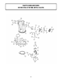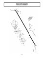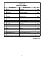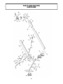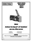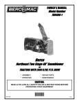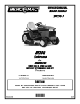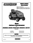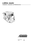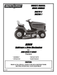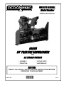
1
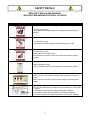
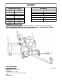
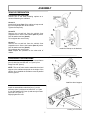
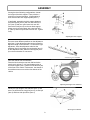
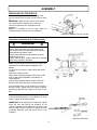
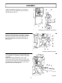
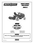
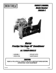
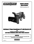
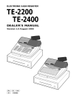
OWNER’S MANUAL
Model Number
700360-9 Snowblower
BERCO
54’’ PRESTIGE SNOWBLOWER
for
ALL TERRAIN VEHICLES
* ASSEMBLY
* REPAIR PARTS
* OPERATION
* MAINTENANCE
CAUTION:
READ & FOLLOW ALL SAFETY RULES & INSTRUCTIONS BEFORE
OPERATING YOUR EQUIPMENT
106250_EN
*106250*
1
M-01
LIMITED WARRANTY
Conditions and Products Covered:
BERCOMAC guarantees any part of the product or accessory
manufactured by BERCOMAC and found in the reasonable
judgment of BERCOMAC to be defective in material and or
workmanship will be repaired or replaced, at its option, by an
authorized dealer without charge up to our maximum labor rates
and pre-established times. For replacement parts only standard
ground freight services are covered. This warranty applies to
the products bought and used in North America.
NOTE: All warranty work must be performed by an
authorized BERCO dealer using original (manufacturer)
replacement parts.
Owner’s Responsibilities:
BERCO’s defective equipment or part must be returned to an
authorized BERCO dealer within the warranty period for
repairs. In the event that defective merchandise must be
returned to manufacturer for repairs, freight fees are prepaid
and a written authorization either BERCOMAC or KIMPEX
must be obtained prior to the shipment. This warranty extends
only to equipment operated under normal conditions. To
validate a warranty claim, it is the user’s responsibility to
maintain and service the unit as specified in the owner’s
manual or to have the unit serviced at their dealer at their
expense.
Warranty Period
(from date of the original retail purchase)
• Residential use: 1 year
• Semi-commercial, professional or rental use: 90 days
Exceptions Noted Below; Despite the fact that the following
items are considered wear parts, they have a different
coverage condition and limited time:
• Tire Chains:
• 90 days, residential use
• No warranty for semi-commercial, professional or
rental use
Engines: Will vary as per the manufacturer
Please refer to the engine manufacturer’s warranty
statement included with the unit. BERCOMAC is not
authorized to handle warranty adjustments on engines.
General Conditions:
The sole liability of BERCOMAC with respect to this warranty
shall be strictly and exclusively repair and replacement as
mentioned herein. BERCOMAC shall not have any liability for
any other costs, loss or damage, including but not limited to,
any incidental or consequential loss or damage.
Taking advantage of the warranty does not in any way extend
the length or renewal of the warranty.
Items and Conditions NOT Covered:
This warranty does not cover the following:
•
•
•
•
•
•
•
In particular, without being limited to, BERCOMAC shall have
no liability or responsibility for:
Pick-up or delivery charges or in-home services fees.
Any damage or deterioration of the unit, parts and or finish
of these due to normal use, wear and tear, or exposure.
Cost of regular use or maintenance service or parts, such as
gas, oil, lubricants, tune-up parts, and adjustments.
Any part or accessory which has been altered, modified,
misused, neglected, accidentally damaged or not properly
installed, improperly maintained, vandalism, theft, fire, water
or damage because of other peril or natural disasters,
stored or repaired not in accordance with the instructions in
the owner’s manual.
Repair due to normal wear and or any wear items include
but are not limited to items, such as shear pins, bolts, belts,
winch cable, cutting edge, skid shoes, etc.
Expedited freight fee services for replacement parts.
Shear bolts and shear pins are to be considered as a
preventive measure not as an assured protection, any
damages resulting from the lack of shear bolts breakage are
not covered.
• Travel time, overtime, after hour time or other extraordinary
repair charges or relating to repairs and or replacements
outside of normal business hours.
• Rental of like or similar replacement equipment during the
period of any, repair or replacement work.
• Any communicating or travel charges.
• Loss or damage to person or property other than that
covered by the terms of this warranty.
• Any claims for lost revenue, lost profit or any similar costs
as a result of damage or repair.
• Attorney’s fees.
BERCOMAC’s responsibility in respect to claims is limited to
making the required repairs or replacement without charge up
to our maximum labour rates and pre-established times and
no claim of breach of warranty shall be cause for cancellation
or rescission of the contract of sale of any product or
accessory. In no event shall recovery of any kind be greater
than the amount of the purchase price of the product sold.
This warranty gives you specific legal rights. You may also
have other rights, which vary from country to country.
NOTE: Bercomac reserves the right to change or improve the design of any part or accessory without assuming any obligation to modify
any product previously manufactured.
Instructions for Obtaining Warranty Services:
Revised 09-28-2011
Contact the BERCO dealer where equipment was purchased or any other authorized service dealer to arrange service at
their dealership. Requests for warranty claims must be carried out through the same distribution network used to
purchase the product. Don’t forget to bring your proof of purchase (sales receipt) to the authorized dealer.
2
TABLE OF CONTENTS
PAGE
INTRODUCTION ...................................................................................................................................................
2
SAFETY PRECAUTIONS .....................................................................................................................................
3
SAFETY DECALS .................................................................................................................................................
5
ASSEMBLY
Conversion Table, Glossary, Tools Required ........................................................................................
Vehicle Preparation .................................................................................................................................
Preparing the Subframe ..........................................................................................................................
Installing on the Vehicle ..........................................................................................................................
Engine Preparation ..................................................................................................................................
Saddle Preparation ..................................................................................................................................
6
7
7
9
11
11
OPERATION
Operating the Snowblower ......................................................................................................................
Electric Controls ......................................................................................................................................
Burnishing Procedure ..............................................................................................................................
Snowblowing Technique ..........................................................................................................................
Skid Shoe Adjustment .............................................................................................................................
12
12
12
13
13
MAINTENANCE
Maintenance ............................................................................................................................................
Adjustments .............................................................................................................................................
Clearing a Clogged Chute .......................................................................................................................
Lubrication ...............................................................................................................................................
Auger and Fan Shear Bolt Replacement ...............................................................................................
Belt Replacement ....................................................................................................................................
Replacing the Augers, Fan and the Gear Box .......................................................................................
14
14
14
15
15
16
16
DISMOUNTING & STORAGE ..............................................................................................................................
18
TROUBLESHOOTING .........................................................................................................................................
19
TORQUE SPECIFICATION TABLE .....................................................................................................................
21
PARTS BREAKDOWN AND PARTS LIST
Rotation System with Chute ....................................................................................................................
Saddle Assembly .....................................................................................................................................
Subframe .................................................................................................................................................
Snowblower .............................................................................................................................................
22
24
26
28
OPTIONS
32
.....................................................................................................................................................
1
INTRODUCTION
TO THE PURCHASER
This new accessory was carefully designed to give years of dependable service. This manual has been provided to
assist in the safe operation and servicing of your attachment.
NOTE: All photographs and illustrations in the manual may not necessarily depict the actual models or attachment, but
are intended for reference only and are based on the latest product information available at the time of publication.
Familiarize yourself fully with the safety recommendations and operating procedures before putting the machine to
use. Carefully read, understand and follow these recommendations and insist that they be followed by those who will
use this attachment.
THIS SAFETY ALERT SYMBOL IDENTIFIES AN IMPORTANT SAFETY MESSAGE IN THIS
MANUAL THAT HELPS YOU AND OTHERS AVOID PERSONAL INJURY OR EVEN DEATH.
DANGER, WARNING, AND CAUTION ARE SIGNAL WORDS USED TO IDENTIFY THE LEVEL OF
HAZARD. HOWEVER, REGARDLESS OF THE HAZARD, BE EXTREMELY CAREFUL.
DANGER:
Signals an extreme hazard that will cause serious injury or death if recommended precautions
are not followed.
WARNING:
Signals a hazard that may cause serious injury or death if the recommended precautions are
not followed.
CAUTION:
Signals a hazard that may cause minor or moderate injury if the recommended precautions are
not followed.
Record your attachment serial number and purchase date in the section reserved below (there is no serial number on
the subframe). Your dealer requires this information to give you prompt, efficient service when ordering replacement
parts. Use only genuine parts when replacements are required.
If warranty repairs are required please present this registration booklet and original sales invoice to your selling dealer
for warranty service.
This manual should be kept for future reference.
Please check if you have received all the parts for your kit with the list of the
bag and the list of the box.
SERIAL NUMBER :
___________________________
(IF APPLICABLE)
MODEL NUMBER:
___________________________
PURCHASE DATE :
___________________________
2
SAFETY PRECAUTIONS
Careful operation is your best insurance against an accident. Read this section carefully before operating the vehicle
and accessory. This accessory is capable of amputating hands and feet and throwing objects. Failure to observe the
following safety instructions could result in serious injury. All operators, no matter how experienced they may be,
should read this and other manuals related to the vehicle and accessory before operating. It is the owner's legal
obligation to instruct all operators in safe operation of the accessory.
GLOSSARY:
4. Handle fuel with care, it is highly flammable.
a) Use approved fuel container.
b) Never add fuel to a running engine or hot engine.
c) Fill fuel tank outdoors with extreme care. Never fill
fuel tank indoors.
d) Never fill containers inside a vehicle, or on a
truck or a trailer bed with a plastic liner. Always
place containers on the ground, away from your
vehicle, before filling.
e) When
practical,
remove
gas-powered
equipment from the truck or trailer and refuel it
on the ground. If this is not possible, then refuel
such equipment on a trailer with a portable
container, rather than from a gasoline
dispenser nozzle.
f) Keep the nozzle in contact with the rim of the
fuel tank or container opening at all times, until
refueling is complete. Do not use a nozzle lockopen device.
g) Replace fuel cap securely and wipe up spilled
fuel.
h) If fuel is spilled on clothing, change clothing
immediately.
In this manual, right and left sides are determined by
sitting on the seat of the vehicle facing forward.
In this manual, "accessories" means attachments
(snowblower, rotary broom, blade etc.) that you install
on the vehicle (lawn tractors, A.T.V. s etc).
TRAINING:
This symbol, "Safety Alert Symbol", is used
throughout this manual and on the
accessory’s safety labels to warn of the
possibility of serious injury. Please take
special care in reading and understanding
the safety precautions before operating the
vehicle and accessory.
1. Read this owner's manual carefully. Be thoroughly
familiar with the controls and proper use of the
vehicle and accessory. Know how to stop the unit
and disengage the controls quickly.
2. Never allow children to operate the vehicle nor the
accessory. Never allow adults to operate the vehicle
nor the accessory without proper instructions.
3. No one should operate the vehicle nor the
accessory while intoxicated or while taking
medication that impairs the senses or reactions.
5.
Never attempt to make any adjustments while the
engine (motor) is running (except when specifically
recommended by manufacturer).
6.
Let the vehicle and accessory adjust to outdoor
temperatures before using.
7.
Never use an accessory without proper guards,
plates, or other safety protective devices in place
8.
Always make sure to wear the appropriate safety
equipment required (glasses, muffs, mask…) for
each type of product. See operation section.
9.
Always make sure of having safe traction on the
vehicle by using the recommended accessories
(chains, A.T.V. tracks, counterweights…). See
operation section.
4. Keep the area of operation clear of all people,
particularly small children and pets.
PREPARATION:
1. Thoroughly inspect the area where the accessory
is to be used and remove door mats, all foreign
objects and the like.
2. For motorized accessories, disengage all clutches
and shift into neutral before starting engine.
10. Always make sure the all components are correctly
installed. (driveline securely attached and locked at
both ends, belts properly installed…)
3. Do not operate the accessory without wearing
adequate winter outer garments. Avoid loose fitting
clothing that can get caught in moving parts. Wear
footwear that will improve footing on slippery
surfaces.
11. Always handle the winch cable with thick leather
gloves.
12. Never modify the accessory or any part without
the written consent from the manufacturer.
3
SAFETY PRECAUTIONS
OPERATION:
MAINTENANCE AND STORAGE
1.
Do not put hands or feet near, under or inside rotating
parts.
2.
Exercise extreme caution when operating on or
crossing gravel drives, walks or roads. Stay alert for
hidden hazards or traffic. Do not carry passengers.
3.
After striking a foreign object, stop the engine (motor),
disconnect the wire from the spark plug(s) and keep
wire away to prevent accidental starting. Thoroughly
inspect the accessory for any damage and repair
damage before restarting and using the accessory.
4.
If the unit should start to vibrate abnormally, stop the
engine (motor) and check immediately for the
cause. Vibration is generally a warning of trouble.
5.
Take all possible precautions when leaving the
vehicle unattended. Disengage the power take-off,
lower the attachment, place the transmission into
neutral, set the parking brake, stop the engine and
remove the contact key.
6.
Do not run the engine indoors, except when starting
the engine and for transporting in or out of the
building. Do not operate or let motor run in a storage
area without ventilation because gas contains
carbon monoxide which is odorless, colorless and
can cause death.
7.
Never use the accessories across the face of
slopes, go from top to bottom. Exercise extreme
caution when using equipment on slopes. Do not
attempt to clear a steep slope.
8.
Never tolerate bystanders in the working zone.
Never use an accessory in the direction of
bystanders, it might throw gravel or debris that can
hurt people or damage property.
9.
Never operate the accessory at high transport
speeds on slippery surfaces. Use care when
backing up.
1.
When cleaning, repairing or inspecting the vehicle
and accessory, make certain that all moving parts
have stopped. For gasoline engine, disconnect wire
from the spark plug(s) and keep wire away to
prevent accidental starting.
2.
Check all the bolts and components at frequent
intervals to make sure that they are properly
tightened.
3.
Never store a motorized accessory with fuel in the
fuel tank inside a building where ignition sources are
present such as hot water and space heaters,
clothes dryers, and the like. Allow the engine to cool
before storing in any enclosure.
4.
Always refer to the owner’s manual when you store
the accessory and vehicle for a prolonged or an
unspecified length of time.
5.
Maintain or replace safety and instruction labels, as
necessary.
6
For winter accessories, (if applicable), let the engine
run for a few minutes after clean snow in order to
prevent the rotary parts from freezing.
7.
Inspect the vehicle’s and accessory’s air filter (if
applicable) every day. Clean it or replace it as
necessary. Change the oil more often when working
in dusty conditions. See the vehicle’s and
accessory's owner’s manual.
10. Do not carry passengers.
11. Disengage power to the accessory when it is
transported or not in use.
THIS SYMBOL MEANS
DANGER !
BECOME ALERT !
YOUR SAFETY IS INVOLVED !
12. Never operate the accessory without good visibility
or light.
13. Keep the accessory away from heat sources or
flames.
14. Never handle the winch cable or hook while in
tension.
4
SAFETY DECALS
REPLACE IF DECALS ARE DAMAGED
SEE PARTS BREAKDOWN FOR DECAL LOCATION
Symbol
Decal #105126
Description
To avoid serious injury:
Keep hands, feet & clothing away from rotating auger while engine is
running.
Decal #105127
To avoid serious injury:
Keep hands out of this discharge chute while engine is running.
Decal #105128
To avoid serious injury:
Keep hands, feet & clothing away.
Do not attempt to install or remove drive belt without reading owner’s
manual.
Decal #105130
Before installing or using:
Locate, read and make sure to understand all of the owner’s manual.
Decal #105131
Refer to owner’s manual about wearing safety glasses, ear muffs and
mask.
Refer to owner’s manual for use of counter weights, cat tracks and tire
chains.
1-Do not drive faster than 3 KM/H when the snowblower is in operation.
2-Do not drive faster than 10 KM/H when the snowblower is in the raised
position.
3-The head of the snowblower weighs 96 kg (without engine).
4-The engine wattage (See specification of the engine installed).
5-The sound pressure level (See specification of the engine installed).
5
ASSEMBLY
GLOSSARY
CONVERSION TABLE
Quad = V.T.T., A.T.V.
1’’ (po, in)
25.4 mm
1’ (pi, ft)
0.3 m
1 psi (lb/in2)
6.89 kPa
1 lb
0.45 kg
1 lbf
4.4 N
Power take-off
(P.T.O)
1 m/h (mi/h)
1.61 km
Prise de force
(P.D.F)
1 hp (cv)
0.75 kW
Véhicule tout terrain
V.T.T.
All terrain vehicle
A.T.V.
P.T.O. = P.D.F
ASSEMBLY INSTRUCTIONS
IMPORTANT: UNLESS OTHERWISE SPECIFIED TORQUE ALL BOLTS ACCORDING TO TORQUE
SPECIFICATION TABLE (SEE TABLE OF CONTENTS) WHEN STATED: TIGHTEN FIRMLY. REFER TO
PARTS BREAKDOWN SECTION FOR PART IDENTIFICATION.
TOOLS REQUIRED
Overall view
3 Wrenches 9/16’’, 1/2’’, 3/4’’
1 Ratchet
3 Sockets 9/16’’, 1/2’’, 3/4’’
1 Wrench (for the nuts on the vehicle’s battery
posts)
1 Wooden block
6
ASSEMBLY
VEHICLE PREPARATION
FASTENING THE SUBFRAME
Choose one of the three following options as a
means of fastening the subframe.
OPTION A:
Install the lift strap (item 1) by making a loop around
the front suspension arm of the vehicle.
Tighten the loop firmly.
OPTION B:
Remove the nut and bolt from the vehicle’s front
suspension arm. Secure the bracket (item 3) with a
bolt, flat washer and nut (item 2).
Do not tighten the nut too firmly.
OPTION C:
Remove the nut and bolt from the vehicle’s front
suspension arm. Secure the bracket (item 4) with a
bolt, flat washer and nut (item 2).
Do not tighten the nut too firmly.
NOTE: Repeat the operation on the other side of
vehicle.
Install the lift strap or the brackets
PREPARING THE SUBFRAME
Assemble the wheel support (item 1) on the subframe
(item 2) with four hex bolts 3/8" x 1" (item 3) four
flange nuts 3/8" (item 4).
NOTE: The set of holes used to assemble the wheel
support to the subframe depends on the height of the
vehicle. Once installed the subframe must be parallel
with the ground.
Install the wheel support
Install the assembled turnbuckles (item 1) on the
subframe (item 2) with two hex bolts 5/16" x 1" (item
3), two flat washers 3/8" (item 4) and two nylon insert
lock nuts 5/16" (item 5).
Slightly tighten the nuts.
Installing the turnbuckles
7
ASSEMBLY
Among the three following configurations, choose
the height of the hitch support. There must be a
maximum of ground clearance. (Configuration A)
does not have the hitch support plates (item 1).
If applicable, assemble the hitch support plates on
the hitch support (item 2) with four hex bolts 3/8" x
3/4" (item 3) and four nylon insert lock nuts 3/8".
Secure the hitch (item 4) on the two hitch support
plates or on the hitch support with a hex bolt 3/8" x
3" (item 5) and one nylon insert lock nut 3/8". Tighten
firmly
Adjusting the hitch support
There are seven different positions on the adjustment
tube (item 1) (the adjustment tube can be inverted) to
adjust the length of the subframe. To choose the right
adjustment, insert the adjustment tube into the
subframe (item 2) and insert the rear bracket (item 3)
on the adjustment tube. Slide the hitch support (item
4) on the rear bracket. Do not secure.
Assembling the subframe
Drive the vehicle over the subframe,
Place the hitch under the tow hitch ball and make
sure there is at least 7" (180 mm) between tube on
the wheel support (item 1) and the most advance part
of the front of the vehicle. Furthermore, the wheels of
the subframe must not touch the front wheels of the
vehicle.
Adjusting the length of the subframe
Identify the right length of the subframe (item 1) and
secure in place with two long pins (item 2), a short pin
(item 3) and three hair pins 3mm (item 4).
Securing the subframe
8
ASSEMBLY
INSTALLING ON THE VEHICLE
Place the hitch (item 1) on the tow hitch ball and
secure in place with a pin (item 2) and a hair pin (item
3).
IMPORTANT: Make sure the vehicle never comes
into contact with the subframe even when the
vehicle’s suspensions are compressed to the
maximum.
NOTE: It is possible to turn the hitch support to
facilitate driving the vehicle over the subframe.
Installing the subframe on the tow hitch ball
Operation instructions for hitch coupler:
WARNING
TO PREVENT INJURIES:
Always check that ball is completely inserted into
hitch coupler socket and that under jaw is securely
closed around the bottom of ball.
Always check that hitch coupler handle is properly
locked before its use.
Always examine hitch coupler and ball for damage
before using, replace if damaged.
NOTE: Correct adjustment will allow the handle to be
released with moderate pressure applied to the
handle.
To open, pull up on hitch coupler handle and rotate
forward.
Place hitch coupler on ball.
When ball is completely nested in ball socket, rotate
hitch coupler handle backward until handle is in
locked position.
Always check tightness before using the tow hitch.
Be sure hitch coupler handle is in locked position.
Lock the handle (item 1) into position over the ball in
the hitch coupler. Tighten the lock nut (item 2) against
the spring so that the hitch coupler is not loose on the
ball.
Hook the turnbuckles (item 1) in the brackets or the lift
straps. Tighten the turnbuckles firmly.
IMPORTANT: After adjusting the turnbuckles, tighten
firmly the nuts that secure the brackets on the
vehicle’s suspension arms. Make sure to lock the nuts
with the original locks. Furthermore, tighten firmly the
turnbuckle assembly nuts that secure them to the
subframe.
Install the turnbuckles
9
ASSEMBLY
Install the snowblower hitch (item 1) on the wheel
support (item 2) of the subframe with a pin (item 3)
and hair pin 4mm (item 4).
Assembling the snowblower to the subframe
Secure the winch hook (item 1) in the lift eye on the
hitch (item 2). Place the winch cable (item 3) between
the engine support (item 4) and the pulley (item 5).
Secure the pulley with a pin (item 6) and a hair pin
3mm (item 7).
Install the snowblower lift system
In the case that the winch is not strong enough to lift
the snowblower, it is possible to install the lift system
as follows:
Attach the lift strap (optional) (item 1) to a well
anchored part of the vehicle. Secure the winch hook
(item 2) in the lift strap. Place the winch cable around
the pulley (item 3). Secure the pulley in place with a
pin (item 4) and a hair pin (item 5).
Lift system
10
ASSEMBLY
ENGINE PREPARATION:
CAUTION
Oil must be added to this motor.
Please refer to motor’s owner’s manual for
instructions and proper winter oil recommendations.
Connecting the wire assembly:
The kit is equipped with a connector which will permit
you to remove the snowblower quickly without having
to remove the wiring.
Place and tie the wires in an appropriate place under
the A.T.V. since they will stay there permanently.
Connect the red wire (positive) to the ATV battery.
Connect the black wire (negative) on a bolt that is on
the A.T.V. frame (scrape away any paint to make sure
the contact is good) and retighten the bolt.
Wire assembly
Fill the gas tank with unleaded gasoline. Wipe off any
spilled gasoline.
SADDLE PREPARATION:
NOTE: All the electrical system is already installed
and connected
components.
to
the
various
snowblower
Place the saddle assembly on the A.T.V. seat.
Place and tie the wire protector in an appropriate
place so the wire protector does not interfere with any
hot or moving parts
Item 1: P.T.O. Switch
Item 2: Ignition & Light Switch
Item 3: Switch (deflector)
Item 4: Throttle Control
Item 5: Switch (chute rotation)
Item 6: Choke Control
Item 7: Safety Switch
11
Saddle controls
OPERATION
WARNING
WARNING
Read the vehicle's owner’s manual carefully. Be
thoroughly familiar with the controls & proper
use of the attachment. Know how to stop the
Never touch with your hands or feet the
snowblower’s fan, auger or the chute because
this is the most frequent cause of accidents
associated with snowblowers.
unit & disengage the controls quickly.
WARNING
WARNING
TO PREVENT INJURIES:
Start the engine, engage and disengage the
clutch to be sure it functions normally. Make
sure the emergency switch is working perfectly.
Make sure all the controls are working well.
To prevent accidents :
-Always use the snowblower in well lighted
areas.
-It is essential to install and use a light on the
front of the snowblower for night use or in
shadowy conditions.
DANGER
Never let the snowblower motor run without the
belt guard in place.
WARNING
To prevent injuries and for more traction when
using the snowblower:-Do not drive faster than 3 km/hr (2 m/hr) with
snowblower on the ground.
-Do not drive faster than 10 km/hr (6 m/hr) with
the snowblower in raised position.
-Always disengage the electromagnetic clutch
when the snowblower is in the raised position.
-Do not operate on a slope greater than 10%.
-Vehicle manufacturer approved tire chains are
required.
-Maximum drawbar pull provided for at the hitch
ball coupling: 3560N (800 lbs)
-Maximum vertical load provided for on the
hitch ball coupling: 360N (80 lbs).
-Ear
muffs
and
safety
glasses
are
recommended.
OPERATING THE SNOWBLOWER
You must be sitting on the saddle in order to
start the snowblower engine.
a) Make sure the snowblower is clear of snow
before engaging the snowblower.
b) Make sure that the auger and fan operate freely.
c) Start the snowblower engine.
d) Before engaging the snowblower drive, always
have the engine running at medium R.P.M.
e) Operate the snowblower at maximum engine
R.P.M.
IMPORTANT: USE FULL ENGINE R.P.M. WHEN
REMOVING WET, STICKY SNOW. LOW R.P.M.
POWER WILL TEND TO PLUG THE CHUTE.
ELECTRIC CONTROLS
See saddle preparation for identification of the saddle
controls.
BURNISHING PROCEDURE
The burnishing procedure must be performed before
the first time use and after each prolonged period of
inactivity. Burnishing the engaging system will ensure
a proper performance and will help avoid damages.
1. Make sure the fan and the augers are free of any
obstruction. Start the motor.
2. Engage electric clutch.
3. Disengage electric clutch and wait for all moving
parts to stop.
4. Repeat procedure (steps 2 & 3) 10 times at 30
seconds intervals to avoid overheating the clutch
which will damage it.
RAISING AND LOWERING THE SNOWBLOWER:
Use the winch switch control to raise and lower the
snowblower.
IMPORTANT: To prolong the subframe’s life, release
the switch immediately when the attachment hits the
stopper in the highest position.
TURNING THE CHUTE AND DEFLECTOR:
Use the switches on the saddle to turn the chute and
to raise or lower the deflector.
ENGAGING
AND
DISENGAGING
THE
SNOWBLOWER:
Engage the snowblower when the engine is running
at medium R.P.M. by pulling the P.T.O. switch.
12
OPERATION
ADJUSTING THE PRESSURE OF THE
SUBFRAME TIRES ON THE GROUND
SNOWBLOWING TECHNIQUE
When removing snow, do not use the snowblower as
a dozer blade to push snow. Allow snowblower to
ingest snow at its own speed. If the speed of your
A.T.V. is too fast, the snowblower may become
overloaded and plug.
When the ground is soft, the vehicle may lose some
of its manoeuvrability because the tires on the
subframe have a tendency to dig into the ground.
In order to avoid this problem, it is possible to install
the pulley assembly 106140 (item 1) supplied with the
snowblower.
Thread the winch cable through the pulley assembly.
Join the pulley to the eye on the subframe (item 2)
with the chain (item 3) two shackles (item 4).
DANGER
DANGER ZONE
It is the snowblower operator’s obligation to make
sure there are no people or objects that can be
thrown in this zone when the snowblower is running.
Danger zone
Adjusting the pulley assembly
SKID SHOE ADJUSTMENT
NOTE: The closer the pulley assembly is to the
subframe, less the wheels will dig into the ground;
therefore it will be easier to manoeuvre.
NOTE: Make sure you do not compress the vehicle’s
suspension too much when transferring the weight of
the snowblower.
CAUTION: Make sure the subframe does not come
into contact with the vehicle.
Level paved surface: Adjust skid shoes to allow 3/16”
to 1/4" or 5 mm to 7 mm clearance (A) between
cutting edge and surface.
Uneven or gravel surface: Adjust skid shoes to allow
1/2” to 5/8" or 13 mm to 16 mm clearance (A)
between cutting edge and surface.
Skid shoe adjustment
13
MAINTENANCE
WARNING
WARNING
Before doing any snowblower maintenance,
assembling or dismounting:
Apply parking brakes of the vehicle.
Stop the snowblower engine and remove the
ignition key
Disconnect the wire from the spark plug(s) and
keep away from spark plug(s) to prevent
accidental starting.
-Do not attempt to clear plugged chute, auger or
fan of snow while the snowblower's engine is
running.
-Disengage snowblower.
-Lower snowblower onto ground.
-Set the parking brake.
-Stop engine, remove the ignition key, disconnect
the wire from spark plug(s) and keep away from
spark plug(s) to prevent accidental starting.
-Make sure all moving parts have stopped.
-Do not use hand to unplug chute, use the chute
shovel supplied with the snowblower.
WARNING
If the snowblower is in the raised position,
always make sure to provide adequate blocking
before working under the snowblower.
CLEANING
CHUTE
ENGINE MAINTENANCE
SNOWBLOWER MAINTENANCE
Check mounting bolts at frequent intervals for proper
tightness in order to prevent costly repairs. Make sure
your snowblower is in safe working condition.
THE
TIRES
ON
CLOGGED
DISCHARGE
Whether it is the snowblower auger, the fan or the
chute that clogged, it is essential to follow these
instructions to the letter.
1. Disengage the electromagnetic clutch
2. Lower the snowblower to the ground and apply
the vehicle’s hand brake;
3. Stop the snowblower engine, remove the key and
wait for all the rotating parts to stop turning.
4. Disconnect the wire from the spark plug(s) and
keep away from spark plug(s) to prevent
accidental starting;
Maintain the engine according to the instruction in the
engine’s owner’s manual.
PRESSURE OF
SUBFRAME
A
WARNING: Always use the chute shovel supplied with
the snowblower in order to unclog the snowblower,
never use your feet or hands.
THE
Verify and adjust the pressure of the tires of the
subframe at 50 psi.
The tire pressure must be even on both sides.
SNOWBLOWER PULLEY REPLACEMENT
OR ALIGNMENT
Clean the parts before aligning or replacing the pulley.
Apply some "Locktite" 2760 on the key and the set
screws. Tighten firmly.
CUTTING EDGE MAINTENANCE
Verify from time to time the wearing on the cutting
edge to make sure you do not wear out the base of
the snowblower’s chassis. This cutting edge is
reversible. Unscrew the bolts and turn the cutting
edge,
Reinstall with new carriage bolts 5/16’’ x 3/4’’ grade 5
and new lock nuts 5/16’’.
14
MAINTENANCE
LUBRICATION
AUGER
AND
REPLACEMENT
SUBFRAME WHEELS: Grease the wheel axles, the
fork pivots after every sixteen hours of use.
Apply oil at all pivot points.
SHEAR
BOLT
IMPORTANT: The shear bolts are to be considered a
preventive measure and not an assured protection.
Operator vigilance is required. Thoroughly inspect the
areas where the snowblower is to be used and remove
all foreign objects.
CHUTE ROTATION SYSTEM: Oil the base of the
chute every sixteen hours of operation.
GEAR BOX :
Check the oil annually. If necessary, add AGMA 4 EP or
SAE 90 oil.
The gear box should have a total of 275ml of oil or filled
to the rim of the bolt hole when installed on the
snowblower.
TO AVOID DAMAGE TO THE SNOWBLOWER:
Use only the original shear bolts
(#103999 for the fan et #104000 for the auger).
The use of any other shear bolt will not insure any
protection and may void the warranty.
IMPORTANT: When replacing the auger shear bolts it is
very important to replace the augers in the same
position as shown to avoid damage to the snowblower
and to ensure maximum efficiency.
Oil level in the gear box
Shear bolt
15
MAINTENANCE
CAUTION
BELT TENSION ADJUSTMENT
If the spring becomes too stretched, it is possible to
the change the position of the spring on the tensioner.
Just move the carriage bolt (item 1), the sleeve (item
2) the flat washer (item 3) and nut (item 4) to position
B instead of position A.
Never use the snowblower without the belt guard.
BELT REPLACEMENT
Use a BX-55 (#106110) as a replacement belt.
1. Remove the belt guard (item 1) by removing the
three hex bolts 1/4" x 1/2" (item 2) and the three
spring washers 1/4" (item 3);
2. Remove the hair pin (item 4) and pin (item 5);
3. Raise the tensioner (item 6) to remove the tension
on the belt (item 7);
4. Remove the old belt and install the new one;
5. Reapply the tension on the belt by lowering the
tensioner;
6. Make sure the flat idler tensioner pulley is properly
aligned on the pulley.
7. Secure the tensioner with the pin and hair pin;
8. Reinstall the belt guard and secure it with three
bolts and three spring washers;
9. Make sure the electromagnetic clutch pulley does
not rub on the belt guard.
Adjusting the tension on the belt
Too much tension on the belt will
considerably reduce the belt’s life span.
Ideally, 7 lbs (30N) of force are needed to obtain a
7/32" (5mm) deflection (see picture below).
WARNING:
Measure the tension on the belt
Belt replacement
16
MAINTENANCE
6. Loosen the two set screws (item 1) from ball
bearing behind the snowblower (it may be
necessary to heat the set screw and the center of
the bearing around the shaft to soften the Loctite).
REPLACING THE AUGERS, FAN AND /
OR THE GEAR BOX
To identify the part numbers, refer to the snowblower
parts breakdown.
NOTE: The snowblower must be disconnected and
removed from the vehicle before replacing the auger
or the gear box.
1. If applicable, remove the gas tank from the support
and place it on the ground (to prevent any risks of
spills);
2. Remove the belt guard & belt (see belt
replacement section);
3. Remove the hex bolts 7/16’’ x 1 1/4’’ (item 1) and
the hex bolts 1/4’’ x 3/4’’ (item 2). Remove the hitch
from the snowblower.
Loosen the set screws from the ball bearing
7. Remove all the bolts (item 3) and nuts supporting
the gear box, it’s support and augers.
8. Remove the assembly (the gear box, its support,
fan, the snowblower augers keeping the nylon
bushings and the bearings;
9. Replace the appropriate parts making sure to
reassemble the parts as shown in figure below.
10 Reinstall the parts.
IMPORTANT: Clean the parts and apply some Loctite
2760 on the key of the pulley and on the set screws of
the bearings and those of the pulley. Firmly tighten
the set screws.
Remove the V pulley
4. Loosen the two set screws (item 1) from the V
pulley (it may be necessary to heat the set screw
and the center of the pulley around the shaft to
soften the Loctite).
5. Remove the V pulley with a puller.
Remove the bolts
Remove the V pulley
17
DISMOUNTING AND STORAGE
DISMOUNTING
STORAGE
1. Select a level surface, set the parking brake, stop
the engine and remove the ignition key to prevent
accidental starting.
2. Lower the accessory to the ground
3. Disconnect the electrical wiring on the front of the
vehicle.
4. Unhook the winch hook and remove the winch
cable from the pulley.
5. Unhook the turnbuckles from the front of the
vehicle. (Tip: loosen one of the turnbuckles in
order to keep the adjustment) and the hitch from
the rear of the vehicle.
6. Remove the vehicle.
1. Clean the snowblower and subframe thoroughly.
2. Paint all the parts wear the paint has worn out.
3. List the parts that will be needed to be replaced
next season.
4. Follow the instructions in the lubrication section.
5. Follow the instructions in the engine owner’s
manual
6. Store the snowblower and subframe in a dry place.
18
TROUBLESHOOTING
* Please refer to parts breakdown section for parts identification.
PROBLEM
Snowblower vibrates or is
abnormally noisy or bouncing.
POSSIBLE CAUSES
CORRECTIVE ACTION
Damaged pulley
Replace pulley
Damaged bearing
Replace the bearing
Fan or the augers are damaged
Remove and straighten or replace the
parts
Fan or auger bushings are worn
Replace with new bushings
Augers are not positioned properly
Position the augers at 180 degrees
from one another. See shear bolt
replacement in manual.
Fan stops turning
Shear bolt is probably broken
Replace shear bolt (see maintenance
section).
Auger stops turning
Shear bolt is probably broken
Replace shear bolt (see maintenance
section).
Snowblower stops turning.
Belt is probably damaged or broken
Check and replace damaged belt
Belt is snapping, shredding,
burning or worn in a specific
place
Snowblower was engaged when
plugged
Make sure the auger and the fan are
not frozen or plugged before
engaging
Lack of tension on the belt
Adjust the tensioner spring or replace
spring if stretched.
Not the original belts
Always use the original belts
Worn belt, Belt may be worn causing
a slack.
Inspect the belt. Replace if required.
Not the original shear bolts
Always replace the shear bolts with
an original bolt.
Imperfections in the pulleys
Verify if the pulleys are damaged.
Verify that the pulleys are smooth
without rust spots. Sand down the
pulleys or replace them.
Interference
Make sure that the belt does not
come into contact with any other part,
bolts, guides etc… when engaged.
Dirt or ice may be underneath chute.
Dismount chute. Clean the base of
chute and the rotation ring. Lubricate
& re-install.
Belt shows premature wear
Chute rotation is difficult
19
TROUBLESHOOTING
* Please refer to parts breakdown section for parts identification.
PROBLEM
Chute plugs easily.
POSSIBLE CAUSES
CORRECTIVE ACTION
Snowblower engine running too
slowly.
Run engine at full R.P.M. during
snow blowing operation.
Advancing too quickly with vehicle.
Reduce vehicle’s speed..
Allow snowblower to ingest snow at
its own speed.
Snowblower digs into ground.
Ground is not frozen or too soft.
Adjust skid shoes lower so they may
better support the snowblower. If
problem persists, change skid shoes
for heavy duty skid shoes (option
#700243) which cover more surface
and prevents snowblower from
digging.
The engine does not start
The P.T.O. switch is pulled up.
The P.T.O. switch must be pushed
down to start the engine of the
snowblower. You must be seated on
the saddle to start the engine.
Other reasons.
See owner’s manual
Overheating of the motor.
These motors are equipped with an
internal protector. Wait 10 minutes
before using.
Frozen motor or chute.
Slap the chute or wiggle from side to
side.
Defective control box or broken wire
harness.
Replace control box or wire harness.
Loose connectors or oxidation on
connectors or motor.
Retighten or clean connectors. Or
replace connector part # 106201.
Snowblower does not rise
evenly.
Pressure of the subframe tires is
uneven from one side to another.
Tire pressure must be even on both
sides. 50 p.s.i.
Electric clutch slips
Insufficient electrical current.
Recharge vehicle’s battery.
Electrical current is cut off.
Replace damaged wiring.
Clutch basket is contaminated.
Clean plates with brake cleaner.
Electric chute motor does not
work.
Electric clutch is noisy or vibrates Mounting bolts are loose.
abnormally.
Certain clutch components may be
damaged.
20
Tighten or replace bolts.
Repair or replace damaged
components.
TORQUE SPECIFICATION TABLE
GENERAL TORQUE SPECIFICATION TABLE
USE THE FOLLOWING TORQUES WHEN SPECIAL TORQUES ARE NOT GIVEN
NOTE: These values apply to fasteners as received from supplier, dry or when lubricated with normal oil. They do not
apply if special graphited or moly disulphide greases or other extreme pressure lubricants are used. This applies to
both UNF and UNC threads.
* Thick nuts must be used with grade 8 bolts
SEE Grade No.
BOLT HEAD
IDENTIFICATION
MARKS AS PER GRADE
NOTE MANUFACTURING
MARKS W ILL VARY
BOLT SIZE
Inches
2
5
8*
TORQUE
TORQUE
TORQUE
FOOT POUNDS
Millimetre
NEW TON-METERS
FOOT POUNDS
NEW TON-METERS
FOOT POUNDS
NEW TON-METERS
Min.
Max.
Min.
Max.
Min.
Max.
Min.
Max.
Min. Max.
Max.
Min. Max.
Max.
1/4"
6.35
5
6
6.8
8.13
9
11
12.2
14.9
12
15
16.3
30.3
5/16"
7.94
10
12
13.6
16.3
17
20.5
23.1
27.8
24
29
32.5
39.3
3/8"
9.53
20
23
27.1
31.2
35
42
47.5
57
45
54
61
73.2
7/16"
11.11
30
35
40.7
47.4
54
64
73.2
86.8
70
84
94.9
113.9
1/2"
12.7
45
52
61
70.5
80
96
108.5
130.2
110
132
149.2
179
9/16"
14.29
65
75
88.1
101.6
110
132
149.2
179
160
192
217
260.4
5/8"
15.88
95
105
128.7
142.3
150
180
203.4
244.1
220
264
298.3
358
3/4"
19.05
150
185
203.3
250.7
270
324
366.1
439.3
380
456
515.3
618.3
7/8"
22.23
160
200
216.8
271
400
480
542.4
650.9
600
720
813.6
976.3
25.4
250
300
338.8
406.5
580
696
786.5
943.8
900
1080
1220.4
1464.5
1"
METRIC BOLT TORQUE SPECIFICATIONS
Size Screw
Grade No.
Pitch (mm )
M6
4T
7T
8T
4T
7T
8T
4T
7T
8T
4T
7T
8T
4T
7T
8T
4T
7T
8T
4T
7T
8T
4T
7T
8T
1.00
M8
M10
M12
M14
M16
M18
M20
1.25
1.50
1.75
2.00
2.00
2.00
2.50
COARSE THREAD
Foot Pounds
Newton-Meters
3.6
5.8
7.2
7.2
17
20
20
34
38
28
51
57
49
81
96
67
116
129
88
150
175
108
186
213
-
5.8
9.4
10
14
22
26
25
40
46
34
59
66
56
93
109
77
130
145
100
168
194
130
205
249
4.9
7.9
9.8
9.8
23
27.1
27.1
46.1
51.5
37.9
69.1
77.2
66.4
109.8
130.1
90.8
157.2
174.8
119.2
203.3
237.1
146.3
252
288.6
-
21
7.9
12.7
13.6
19
29.8
35.2
33.9
54.2
62.3
46.1
79.9
89.4
75.9
126
147.7
104.3
176.2
196.5
136
227.6
262.9
176.2
277.8
337.4
Pitch (mm )
FINE THREAD
Foot Pounds
Newton-Meters
-
1.00
1.25
1.25
1.50
1.50
1.50
1.50
12
19
22
20
35
40
31
56
62
52
90
107
69
120
140
100
177
202
132
206
246
-
17
27
31
29
47
52
41
68
75
64
106
124
83
138
158
117
199
231
150
242
289
16.3
25.7
29.8
27.1
47.4
54.2
42
75.9
84
70.5
122
145
93.5
162.6
189.7
136
239.8
273.7
178.9
279.1
333.3
-
23
36.6
42
39.3
63.7
70.5
55.6
92.1
101.6
86.7
143.6
168
112.5
187
214.1
158.5
269.6
313
203.3
327.9
391.6
PARTS BREAKDOWN
ROTATION SYSTEM WITH CHUTE
22
PARTS LIST
ROTATION SYSTEM WITH CHUTE
Ref.
Réf.
English description
Description française
Qty.
Qté.
Part #
Pièce #
1
Chute
Goulotte
1
106172
2
Bracket
Support
1
103971
3
Reinforcement plate
Plaque de renforcement
1
103972
4
Spacer
Espaceur
3
103368
5
Rotation ring
Anneau de rotation
1
103974
6
Spacer
Espaceur
6
103361
7
Bracket
Support
1
103375
8
Electric motor
Moteur électrique
2
106147
9
Lever
Levier
1
103365
10
Oil lite bushing
Coussinet imprégné d'huile
1
103362
11
Plate
Plaque
1
103363
12
Arm
Bras
1
103364
13
Nylon flat washer 11/32"
Rondelle plate de nylon 11/32"
2
102009
14
Nylon flat washer 7/16"
Rondelle plate de nylon 7/16"
2
102011
15
Rotation ring
Anneau de rotation
1
103943
16
Hand guard
Fourche protectrice
1
102012
17
Protective plate
Plaque protectrice
1
105404
18
Hex. bolt 1/4" n.c. x 3/4" GR5
Boulon hex. 1/4" n.c. x 3/4" GR5
4
O/L
19
Hex. bolt 1/4" n.c. x 1" GR5
Boulon hex. 1/4" n.c. x 1" GR5
4
O/L
20
Hex. bolt 1/4" n.c. x 1 1/2" GR5
Boulon hex. 1/4" n.c. x 1 1/2" GR5
3
O/L
21
Hex. bolt 1/4" n.c. x 1 3/4" GR5
Boulon hex. 1/4" n.c. x 1 3/4" GR5
3
O/L
22
Carriage bolt 1/4" n.c. x 1 " GR5
Boulon à carrosserie 1/4" n.c. x 1 " GR5
2
O/L
23
Carriage bolt 5/16" n.c. x 3/4 " GR5
Boulon à carrosserie 5/16" n.c. x 3/4 " GR5
2
O/L
24
Machine screw T.H. 1/4" n.c. x 1/2"
Vis mécanique T.H. 1/4" n.c. x 1/2"
3
O/L
25
Nylon insert lock nut 1/4" n.c. (thin)
Écrou à garniture de nylon 1/4" n.c. (mince)
15
O/L
26
Nylon Insert lock Nut 5/16" n.c.
Écrou à garniture de nylon 5/16" n.c.
2
O/L
27
Flange nut 1/4" n.c.
Écrou à bride 1/4" n.c.
4
O/L
28
Flat washer 5/16" hole
Rondelle plate 5/16" trou
3
O/L
29
Danger decal chute
Décalque danger goulotte
1
105127
O/L = Obtain Locally
23
PARTS BREAKDOWN
SADDLE ASSEMBLY
24
PARTS LIST
SADDLE ASSEMBLY
Ref.
Réf.
English description
Description française
Qty.
Qté.
Part #
Pièce #
1
Seat cover
Couvre-siège
1
103987
2
Control board
Tableau de contrôle
1
104011
3
Switch support
Support de commutateur
1
104012
4
Safety switch ass'y
Commutateur de sécurité ass'é
1
104014
5
Ignition switch
Commutateur d'ignition
1
104015
6
P.T.O. switch
Commutateur de p.d.f.
1
104016
7
Switch
Commutateur
2
103381
8
Rubber boot
Capuchon de caoutchouc
2
103379
9
Throttle control
Contrôle de l' accélérateur
1
104008
10
Choke control
Contrôle de l' étrangleur
1
104009
11
Wire assembly
Fil assemblé
1
104017
12
Wire assembly
Fil assemblé
1
104018
13
Wire assembly (Incl. 103382)
Fils assemblés (Incl. 103382)
1
104295
14
Shim
Cale
1
104013
15
Breaker
Disjoncteur
1
103382
16
Cap
Capuchon
2
105407
17
Pop-rivet 3/16" no AD-66BS
Rivet pop 3/16 no.AD-66BS
4
O/L
18
Carriage bolt 5/16" n.c. x 1"
Boulon à carrosserie 5/16" n.c. x 1"
2
O/L
19
Flange nut 5/16" n.c.
Écrou à bride 5/16" n.c.
2
O/L
20
Tie wrap 8"
Attache de nylon 8"
12
O/L
O/L = Obtain Locally
25
PARTS BREAKDOWN
SUBFRAME
26
PARTS LIST
SUBFRAME
Ref.
Réf.
English description
Description française
Qty.
Qté.
Part #
Pièce #
1
Subframe
Sous-châssis
1
104957
2
Wheel support
Support de roue
1
104770
3
Rear bracket
Fixation arrière
1
104956
4
Hitch support
Support d'attache
1
104958
5
Adjustment tube
Tube d'ajustement
1
104959
6
Hitch
Attache
1
104639
7
Hitch Ball Support
Support de boule d'attache
1
106214
8
Hitch support plate
Plaque de support d'attache
2
104641
9
Pin
Goupille
1
104642
10
Caster wheel assembly
Roue pivotante assemblée
2
105679
11
Inner tube 250-4
Chambre à air 250-4
1
102675
12
Tire 280/250-4
Pneu 280/250-4
1
102674
13
Chain
Chaîne
3
104633
14
Shackle Ptd Z
Clevis Pqé Z
4
102343
15
Turnbuckle
Tendeur
2
104634
16
Bracket
Fixation
2
104632
17
Bracket
Fixation
2
105194
18
Lift strap
Sangle de relevage
2
103613
19
Hair pin 3mm
Goupille à ressort 3mm
4
102617
20
Hair pin 4mm
Goupille à ressort 4mm
1
102054
21
Pin
Goupille
2
104961
22
Pin
Goupille
1
104999
23
Pin
Goupille
1
104759
24
Pulley assembly
Poulie assemblée
1
106140
25
Hex. bolt 5/16" n.c. x 1" GR5
Boulon hex. 5/16" n.c. x 1" GR5
2
O/L
26
Hex. bolt 3/8" n.c. x 1" GR5
Boulon hex. 3/8" n.c. x 1" GR5
4
O/L
27
Hex. bolt 3/8" n.c. x 3/4" GR5
Boulon hex. 3/8" n.c. x 3/4" GR5
12
O/L
28
Hex. bolt 3/8" n.c. x 3" GR5
Boulon hex. 3/8" n.c. x 3" GR5
1
O/L
29
Nylon Insert lock Nut 5/16" n.c.
Écrou à garniture de nylon 5/16" n.c.
2
O/L
30
Nylon Insert lock Nut 3/8" n.c.
Écrou à garniture de nylon 3/8" n.c.
1
O/L
31
Flange nut 3/8" n.c.
Écrou à bride 3/8" n.c.
16
O/L
32
Flat washer 3/8" hole
Rondelle plate 3/8" trou
4
O/L
O/L = Obtain Locally
27
PARTS BREAKDOWN
SNOWBLOWER
28
PARTS LIST
SNOWBLOWER
Ref.
Réf.
English description
Description française
Qty.
Qté.
Part #
Pièce #
1
Frame 54"
Châssis 54"
1
106161
2
Hitch
Attache
1
106162
3
Bender
Tendeur
1
106163
4
Guard
Garde
1
106164
5
Belt guard
Garde-courroie
1
106166
6
V-belt, BX-55
Courroie en V, BX-55
1
106110
7
Engine support
Support moteur
1
106168
8
Guard
Garde
2
106169
9
Rod end assembly
Embout assemblé
1
106184
10
Bender
Tendeur
1
106175
11
Auger 54" left
Vis 54" gauche
1
104747
12
Auger 54" right
Vis 54" droite
1
104748
13
Shear plate
Plaque de cisaillement
1
103933
14
Fan
Éventail
1
103932
15
Gear box left rotation
Boîte d'engrenage rotation gauche
1
104718
16
Rotation bushing
Coussinet de rotation
4
103946
17
Shear bolt / N.I.L.N. (auger) pkg-10
Boulon de séc. / É.G.N. (vis) pqt-10
2
104000
18
Bearing with set screw
Roulement à billes avec vis à pression
3
102755
19
Shear bolt / N.I.L.N. (fan) pkg-10
Boulon de séc./ É.G.N. (éven.) pqt-10
1
103999
20
V pulley with set screw
Poulie en V avec vis pression
1
105423
21
Flat pulley
Poulie plate
1
102765
22
Flangette
Flangette
2
102680
23
Oil lite bushing
Coussinet imprégné d'huile
2
102784
24
Cutting edge 54"
Racloir 54"
1
104427
25
Key 1/4" x 1/4" x 1 3/4"
Clé 1/4" x 1/4" x 1 3/4"
1
102327
26
Flangette
Flangette
2
102213
27
Gear box support
Support de boîte d'engrenage
1
104746
28
Shaft 54"
Arbre 54"
1
104722
29
Key 1/4" x 1/4" x 2"
Clé 1/4" x 1/4" x 2"
1
102922
30
Spring
Ressort
1
102592
31
Flange washer
Rondelle à bride
1
102081
32
Chute shovel support
Support de pelle à goulotte
1
105701
O/L = Obtain Locally
29
PARTS LIST
SNOWBLOWER
Ref.
Réf.
English description
Description française
Qty.
Qté.
Part #
Pièce #
33
Chute shovel
Pelle à goulotte
1
105700
34
Pin
Goupille
1
105365
35
Hair pin 2mm
Goupille à ressort 2mm
1
102430
36
Spacer
Espaceur
1
103361
37
Pulley
Poulie
1
106138
38
Pin
Goupille
1
103070
39
Skid shoe
Patin
2
103188
40
Hair pin 3mm
Goupille à ressort 3mm
1
102617
41
Electrical Clutch
Embrayage électrique
1
106143
42
Clutch support
Support d'embrayage
1
106277
43
Engine 23 HP (Kohler)
Moteur 23 CV (Kohler)
1
104003
44
Light assembly
Lumière assemblée
1
104973
45
Light bracket
Fixation de la lumière
1
104791
46
Knob
Bouton
1
103027
47
Gasoline tank assembly
Réservoir d'essence assemblé
1
104005
48
Tank support
Support de réservoir
1
104792
49
Wire assembly
Fil assemblé
1
106228
50
Heat shield
Pare-chaleur
1
104621
51
Left drift cutter
Couteau à neige gauche
1
102821
52
Right drift cutter
Couteau à neige droit
1
102822
53
Clutch spacer
Expaceur d'embrayage
1
106216
54
Hex. bolt 1/4" n.c. x 1/2" GR5
Boulon hex. 1/4" n.c. x 1/2" GR5
3
O/L
55
Hex. bolt 1/4" n.c. x 3/4" GR5
Boulon hex. 1/4" n.c. x 3/4" GR5
4
O/L
56
Hex. bolt 1/4" n.c. x 1" GR5
Boulon hex. 1/4" n.c. x 1" GR5
4
O/L
57
Hex. bolt 5/16" n.c. x 3/4" GR5
Boulon hex. 5/16" n.c. x 3/4" GR5
2
O/L
58
Hex. bolt 5/16" n.f. x 3/4" GR5
Boulon hex. 5/16" n.f. x 3/4" GR5
4
O/L
59
Hex. bolt 5/16" n.c. x 2 1/4" GR8
Boulon hex. 5/16" n.c. x 2 1/4" GR8
1
O/L
60
Hex. bolt 3/8" n.c. x 3/4" GR5
Boulon hex. 3/8" n.c. x 3/4" GR5
4
O/L
61
Hex. bolt 3/8" n.c. x 1" GR5
Boulon hex. 3/8" n.c. x 1" GR5
4
O/L
62
Hex. bolt 3/8" n.c. x 1 1/4" GR5
Boulon hex. 3/8" n.c. x 1 1/4" GR5
2
O/L
O/L = Obtain Locally
30
PARTS LIST
SNOWBLOWER
Ref.
Réf.
English description
Description française
Qty.
Qté.
Part #
Pièce #
63
Hex. bolt 3/8" n.c. x 1 3/4" GR5
Boulon hex. 3/8" n.c. x 1 3/4" GR5
4
O/L
64
Hex. bolt 3/8" n.c. x 2 3/4" GR5
Boulon hex. 3/8" n.c. x 2 3/4" GR5
1
O/L
65
Hex. bolt 7/16" n.c. x 1 1/4" GR5
Boulon hex. 7/16" n.c. x 1 1/4" GR5
4
O/L
66
Hex. bolt 7/16" n.f. x 1 1/2" GR5
Boulon hex. 7/16" n.f. x 1 1/2" GR5
1
O/L
67
Carriage bolt 1/4" n.c. x 1 1/4" GR5
Boulon à carrosserie 1/4" n.c. x 1 1/4" GR5
1
O/L
68
Carriage bolt 5/16" n.c. x 3/4 " GR5
Boulon à carrosserie 5/16" n.c. x 3/4 " GR5
12
O/L
69
Socket Head Cap Screw M5 x 0.80 x 10
Vis six PC tête ronde M5 x 0.80 x 10
2
O/L
70
Machine screw T.H. 1/4" n.c. x 1/2"
Vis mécanique T.H. 1/4" n.c. x 1/2"
6
O/L
71
Machine screw Pan head no.10 x 32 x 1 1/2''
Vis mécanique tête pan no.10 x 32 x 1 1/2''
2
O/L
72
Nylon insert lock nut 3/8" n.f.
Écrou garniture de nylon 3/8" n.f.
1
O/L
73
Nylon Insert lock Nut 1/4" n.c.
Écrou à garniture de nylon 1/4" n.c.
9
O/L
74
Nylon Insert lock Nut 5/16" n.c.
Écrou à garniture de nylon 5/16" n.c.
1
O/L
72
Nylon Insert lock Nut 3/8" n.c.
Écrou à garniture de nylon 3/8" n.c.
11
O/L
76
Nylon Insert lock Nut 7/16" n.c.
Écrou à garniture de nylon 7/16" n.c.
4
O/L
77
Flange nut 1/4" n.c.
Écrou à bride 1/4" n.c.
6
O/L
78
Flange nut 5/16" n.c.
Écrou à bride 5/16" n.c.
9
O/L
79
Flange nut 3/8" n.c.
Écrou à bride 3/8" n.c.
4
O/L
80
Stover lock nut 5/16" n.c.
Écrou de blocage 5/16" n.c.
6
O/L
81
Flat washer 5/16" hole
Rondelle plate 5/16" trou
5
O/L
82
Flat washer 3/8" hole
Rondelle plate 3/8" trou
2
O/L
83
Flat washer 7/16" hole
Rondelle plate 7/16" trou
10
O/L
84
Lock washer 1/4"
Rondelle de blocage 1/4"
3
O/L
85
Berco decal
Décalque Berco
1
102471
86
Decal danger auger
Decalque danger vis
1
105126
87
Decal warning safety
Decalque avertissement sécurité
1
105131
88
Decal danger belts
Decalque danger courroies
1
105128
89
Decal read instructions
Decalque lire instructions
1
105130
90
Made in Canada decal
Décalque Fabriqué au Canada
1
REF
91
Specifications decal
Décalque spécifications
1
REF
92
Serial number
Numéro de série
1
REF
O/L = Obtain Locally
31
OPTIONS
EXTENSION AND SIDE WIDENING
ANGLE KIT
#700461 .
Widens the snowblower by
6’’ (15cm)
and adds about 7’’ (18cm) to the
height.
EXTENSION PANEL
#700473
Adds about 10’’ (25cm) to the height
of the snowblower
32
SUBFRAME EXTENSION
#700485
For bigger vehicles
NOTES
33
BY
WHEN PERFORMANCE
& DEPENDABILITY
ARE NON NEGOTIABLE !
Ber comac Limitée
92, For t in Nor t h, Adstock, Quebec, Canada, G0N 1S0
WWW.BERCOMAC.COM
PRINTED IN CANADA
(ORIGINAL NOTICE)
34