1
Operator's
Manual
12"
MINI LATHE
Model No.
351.221060
CAUTION:
Read and follow all Safety
Rules and Operating
Instructions before First
Use of this Product. Keep
this Manual with Tool.
Sears, Roebuck
V_N.
sear
S. CO rn]cra_t
and Co., Hoffman Estates, IL 60179 U.S.A.
s ma n
23139,00 Draft (01/03/05)
I
• Work area should be properly lighted.
Warranty .........................................
2
Safety Rules ....................................
2-3
Unpacking .......................................
3
Assambl_; ........................................
Installation ......................................
Operation .....................................
Maintenance ....................................
• Keep visitors at a safe distance from work area,
- Keep chtidren out of workplace. Make workshop childproof.
Use padlocks, master switches or remove switch keys to
prevent any unintentional use of power tools.
• Keep power cords from coming in contact with sharp
objects, oil, grease, and hot surfaces.
3
TOOL SHOULD
4-5
BE MAINTAINED
• Always unplug tool prior to inspection.
5-13
14
•
Consult manual for specific maintaining and adjusting prccaduFeS,
Troubleshooti ng ..................................
Parts Illustration and List ........................
FULL
ONE YEAR
15
16-17
Keep tool lubricated and clean for safest operation.
Keep all parts in working order. Check to determine that
the guard or other parts will operate property and perform
their intended function.
• Check for damaged parts. Check for alignment of moving
parts, binding, breakage, mounting and any other condition
that may affect a toots operation.
WARRANTY
If this product fails due to a defect in material or workmanship
within one year from the date of purchase, Sears will at its
option repair or replace it free of charge. Contact your nearest
Sears Service Center (1-800-4-MY-HOME) to arrange for
product repair, or return this product to place of purchase for
replacement.
•
A guard or other part that is damaged should be properly
repaired or replaced. Do not perform makeshift repairs.
(Use parts list provided to order replacement parts.)
•
If this product is used for commercial or rental purposes, this .
warranty will appty for 90 days from the date of purchase.
Never adjust attachments while running. Disconnect power
to avoid accidental start-up.
Have damaged or worn power cords replaced immediately
•
Keep cutting tools sharp for effidant and safest operation.
This warranty applies only while this product is used in the
United States.
KNOW
This warranty gives you specific legal rights and you may also
have other fights which vary from state to state.
Sears, Roebuck and Co., Dept. 817WA, Her[man Estates,
IL 60179
•
Avoid ar_.cidentalstart-up. Make sure that the tool is in the
=oil_ position before plugging in, turning on safety disconnect orac_vatingbreakers.
Do not force fool. It will work most eff]cientty at the rate for
which it was designed.
Keep hands away fromchuck,centersand othermoving parts
WARNING:
For your own safety, read all of the instructions
and precautions before operating tool.
Never leavetoctrunningunattendedTurnthepower off
and do not leave tool until
it comes to a complete stop.
Do not overreach. Keep proper footing and balance.
CAUTION: Always follow proper operating procedures as
defined in this manual -- even if you are familiar with usa of
this or similar tools. Remember that being careless for even a
fraction of a second can result in severe personal injury.
BE PREPARED
HOW TO USE TOOL
Use right tool for job. Do not force tool or attachment to do
a job for which it was not designed.
Disconnect tool when changing attachments.
Never stand on tool. Serious injury could occur if tool is
tipped or ff centers are unintentionally contacted.
Know your tool. Learn the tool's operation,
application and
specific limitations.
Handle workplace correctly. Mount firmly in holding
devices. Protect hands from possible injury.
FOR JOB
Wear proper apparel. Do not wear loose clothing, gloves,
nab<ties, rings, brecelets or other jewelry which may get
caught in moving parts of machine,
• Turn machine off if workplace splits or besomes loose.
Wear protective hair covedng to contain fang hair.
Use cuing tools as recommended in =Operation.=
WARNING: For your own safety, do not operate your wood
lathe unUl it is completaly assembled and installed accordingto
instruc'dons.
Wear safety shoes with non-slip soles.
Wear safety glasses complying with United States ANSI
Z87.1. Everyday glasses have only impact resistant lenses.
They are NOT safety glasses.
PROTECTION:
Wear face mask or dust mask if operation is dusty,
EYES, HANDS,
FACE, BODY,
EARS
If any part of your lathe is missing, malfunctioning, or has
been damaged or broken, cease operating immedlataly
until the particular part is properly repaired or replaced.
Be alert and think dearly Never operate power fools when
tired, intoxicated or when taking medications that cause
drowsiness.
•
Keep work area clean. Cluttered work areaa invite accidents.
Wear safety goggles that cornpfy wi_ United States ANSI
Z87.1 and a face shield or dust mask if operation is dusty
Wear ear plugs or muffs during extended periods of operation.
Do not use power tools in dangerous environments. Do not
use power tocts in damp or wet locations. Do not expose
power tools to rain,
Small loose pieces of wood or other objects that contact a
spinning workplace can be propelled at very high speed.
This can be avoided by keeping the lathe clean.
PREPARE WORK AREA FOR JOB
© Seam, Roebuck and Co.
2
N_ver turn the lathe ON before clearing the bed, head and
taifaiock of all tools, wood scraps, etc., except the workplece
and related support devices for the operation planned.
Never perform any operation with this lathe where theworkpiece is hand-held. Do not mount a reamer, milling cutter, drill
bit, wire wheel or buffing wheel to the headstock spindle.
Never place your face or body in line with the chuck or
faceplate.
Never place your f_ngers or hands in path of cutting tools,
When hand-sanding faceplate or between-centers mounted workpieces, complete all sanding BEFORE removing
the workplace from the lathe.
Never nJn the spindle in the wrong direction, The cutting
tool couid be pulled from your hands. The workplace
should always turn towards the operator.
Never reach in beck of the work.piece with either hand to
support the piece, remove wood scraps, or for any other
reason. Avoid awkward operations and hand positions
where a sudden slip could cause fingers or hand to move
into a spinning workpiece.
For spindle turning, ALWAYS poaitior) Me tool rest above the
cente_ne of the werkpiece and spindle (approximately '/R").
Shut the lathe OFF and disconnect power source when
removing the faceplate, changing the center, adding or
removing an auxiliary device, or making adjustments.
WARNING:
Some dust created by power sanding, sawing,
grinding, drilling and other construction activities contains
chemicals known to cause cancer, birth defects or other
reproductive harm.
Turn key lock switch to °off" and remove key when too! is
not in use.
Some examples of these chemicals are:
If the workplace sp£ts or is damaged in any way, turn lathe
OFF and remove the workplace from the holders. Discard
damaged workplace and start with a new piece of wood.
Use extra care when turning wood with twisted grain or
wood that is twisted or bowed -- it may cut unevenly or
wobble excessively.
• Lead from lead-based paints.
• Crystalline silica from bricks and cement and other
masonry products,
• Arsenic and chromium from chemically-treated lumber.
Your risk from these exposures vary, depending on how often
you do this type of work. To reduce your exposure to these
chemicals: work in a well ventilated area and work with
approved aafety equipment. Always wear MSHA/NIOSH
approved, properly fitting face mask or respirator when using
such tools.
KNOW YOUR CUTTING TOOLS
Dull, gummy, improperly
sharpened or set cutting tools can
cause vibration and chatter during cutting operations.
Minimize potential injury by proper care of tools and regu-
tar machine maintenance.
THINK
SAFETY
Safety is a combination
ness at all times when
of operator common sense and alertthe lathe is being uaed.
For your own safety,
operator's
manual
read all rules and precautions
before
Check for shipping damage. If damage has occurred, a claim
must be filed with CaTTier, Check for completeness.
Immediately
repo,-[ missing
in the
using this tool
For eye protection, wear safety glasses
United States ANSI ZB7.1.
parts of machine
or workpiece.
Wear
protective
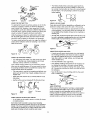
Mounting
attempt
any workpieces
to remount
Guard Assembly
Pen Mandrel
by hand to make sure
turning
the Lathe,
Place two M6 x 12 socket head bolts and fiat washers (Key
Nos. 9 and 25) into a mounting plate (Key No. 26).
•
Thread bolts into the square nuts secureIF
Repeat for other mounting plate.
a between-centers
Insert guard support (Key No. 45) into tool rest base (Key
No. 39). Secure in position with set screw (Key No. 36).
turning
to the faceplate, or a faceplate turning to between-centers,
for aecondary operations. Make sure that the speed is at
the lowest setting
to assemble
Slide a square nut (Key No. 27) into the front and rear
channels of the lathe bed (Key No. 28).
for start-up.
when mounting
do not attempt
Refer to Figure 42.
to the face-
When remounting
a between-centers
turning that has nonaltered original centers, make sure that the speed is at the
Use extra caution
(1), Key No. 50
piece of
Never attempt to remount a between-centers
turning ff the
original centers on the turning have been altered or removed.
lowest setting
(1), Key Nos. 8, 48 and 49
System
plug in the power cord, or turn the _witch on until the missing
parts are obtained and properly installed.
that have splits or knots.
a faceplate
Bolt (4), Key No. 25
ff any parts are mieeing,
plate for any reason.
•
(4), Key No. 9
Support Rod (1), Key No. 46
that there is adequate
clearance. Start the machine on
lowest speed setting to verify that the workplace is secure.
Never
(2), Key No. 26
M6 x 12 Socket Head
For large pieces, create a rough shape on another
equipment before installing on faceplate.
in one carton. Additional
Nut (4), Key No. 27
M6 Flat Washer
hair cover-
Tighten all clamps, tixturee end tailstock before applying
power. Check to make sure that all tools and wrenches
have been removed.
Do not mount
Plate
M6 Square
long hair.
With switch off, rotate workplace
complete
parts which need to be assembled to lathe, should be located
and accounted for before assembly. Refer to Figure 42.
with
Do not wear loose clothing, gloves, neckties, rings,
bracelets or other jewelry that could get caught in moving
ing to contain
parts to dealer.
Ycur wood lathe is shipped
complying
M
•
for start-up.
3
Attach guard assembly to support Secure in posi_on with
wing nut (Key No. 49). Position guard over work.
U
LOCATION
OF WOOD
LATHE
•
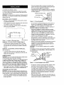
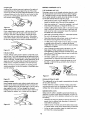
This tool is equipped with an approved 3-conductor cord
rated at 150V and a 3-prong grounding type plug (see F]gure
2) for your protection against shock hazards.
•
Grounding plug should be plugged directly into a properly
installed and grounded 3-prong grounding-type receptacle,
as shown (Figure 2).
The lathe should be positioned so that neither the operator
nor a casual observer is forced to stand in line with the spinning chuck or workpiece.
WARNING: The lathe must be damped mrbolted securely to
work bench. An unbalanced workplace will cause the lathe to
shake and tip over.
MOUNTING
•
•
•
LATHE
Propedy Grounded Outlet
Grouodingprong
4@11
TO BENCH
3-Prong Plug
Dr!l[ four %" holes through the top of the bench as shown
in the following illustration:
Position lathe over the holes and feed 31_,,"
f_at head screws
(not supplied) through holes in lathe bed.
Figure 2 - 3-Prong Receptacle
•
Secure from underneath with fiat washera, lock washers
and hex nuts (not supplied).
_....,e--
Plug must be plugged into matching outtat that is properly
installedand grounded in accordancewith nillocal codes and
ordinances. Do not modify plug provided. If it will not fit in
ou_et, have proper outtat installed by a qualiSed electrician.
Inspect tool coeds periodically and if damaged, have them
repaired by an authorized service fectldy.
I
Rtnt
Figure 1 - Location of Mounting Holes
Green (or green and yellow) conductor in cord is the
grounding wire. If repair or replacement of the electric cord
or plug is necessary, de not connect the green (or green
and yellow) wire to a live terminal
Of Bench
-
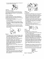
REMOVAL OF SPUR CENTER FROM SPINDLE
•
To remove spur center from spindle, insert a Y4"wood
dowel or brass rod through the hole in the spindle. Hold
the center with one hand and tap the dowel or rod with a
OF BEARING
CENTER
FROM QUILL
This work should be performed by a qualified
A temporary 3-prong to 2-prong grounding adapter (see Figure
3) is available for connecting plugs to a two pete outlet ff it is
properly grounded.
Refer to Figure 42:
•
Where a 2-prong wall receptacle is encountered, it must be
replaced with a properly grounded 3-prong receptacle
installed in accordance with National Etacfric Code and
local codes and ordinances.
WARNING:
etact]ictan.
hammen
REMOVAL
Do not remove or alter grounding prong in any manner. In
the event of a malfunction or breakdown, grounding provides a path of least reeistance for elec'o-ical shock.
WARNING:
Do net permit fingers to touch the terminals of
plug when installing or removing from outlet.
173/="maXl---a,.-___
5V[I l'l
_-'------_'_
To remove bearing center from tai! stoc_kqunl, loosen
handle (Key No. 34) and turn adjustment nut (Key No. 44)
t_vcardsfront of lathe bed.
Grounding Lug
Adapter
Make Sure
Donnected
To
POWER SOURCE
Ground
WARNING:
Do notconnectwood lathe to the power source
until all assernb!y steps have been completed.
The motor is designed for opera,on on the voltage and frequency
specil_ed.Normal loads will be handled safely on voifages not
more than 10% above or below specked voltage.Running the
unit
on voltageswhich are not within range may cause overheating andmotor burn-out. Heavy loads require that voltage at motor
terminals be no less than the voltage specified on nameplate.
• F_:_versupply to the motor is con_'olledby a single pole locking
roci<erswitch.Remove the key to prevent unauthorizeduse.
GROUNDING
Figure 3 - 2-Prong
•
INSTRUCTIONS
WARNING:
Improper connection of equipmentgroundingconductor can result in the dsk of elec_icel shock.Equipment should
be groundedwhile in use to protect operator from elec#'icefshock.
•
Check with a qualified electrician if grounding instruclJons
are not understood or if in doubt as to whether the tool is
properly grounded.
4
2-Prong Receptacle
Receptacle with Adapter
Do not use a 3-prong to 2-prong grounding adapter unless
permitted by local end national codes and ordinances.
(A 3-prong to 2-prong grounding adapter is not permitted
in Canada.) Where permitted, the rigid green tab or terminal
on the side of the adapter must be securely connected to a
permanent electrical ground such as a properly grounded
water pipe, a properly grounded outlet box or a properly
grounded wire system.
Many cover plate screws, water pipes and outlet boxes are
not properly grounded. To ensure proper ground, grounding
means must be tested by a qualified electrician.
EXTENSION
•
•
CORDS
The use of any extension cord will cause some drop in
voltage and loss of power.
Wires of the extension cord must be of sufficientsize to
carry the current and maintain adequate voltage.
Use the table to determine the minimum wire size (A.W.G.)
extension cord.
•
Use only 3-wire extension cords having 3-prong grounding
type plugs and 3-pole receptacles which accept the too_plug.
•
If the extension cord is worn, cut, or damaged in any way,
replace it immediately.
Extension
Refer to Figures 5 - 42.
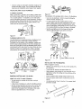
DESCRIPTION
Craftsman 12" 3-speed wood lathe provides capability to turn
wooden workpieces up to 12" long and 4" diameter. The motor
rotates at 3450 RPM and the spindle speeds range from 1350
to 3500 RPM.
Lathe includes 2'/="face plate, spur and bearing centers, safety
guard and pen mandrel system.
SPECIFICATIONS
Cord Length
Turning length (max.) .............................
Wire Size A.W.G.
Up to 25 ft........................................
Swing over bed ...................................
18
235t_," '
5%"
Height .........................................
Spindle speed ......................
8';t,"
1350 to 3500 RPM
Spindle thread ................................
_1,"-'16
Spindle taper .................................
#1MT
Tailstock taper .................................
#1 MT
Tailstock quill travel ..............................
Switch ....................................
_=-S_
Motor ..........................
1'/_"
120V, SP
3450 RPM, 1.2 AMPS
Weight ......................................
_j_Green
GRD
The 120 Vo!t AC motor has the following specifications:
Horsepower (Maximum Developed) ...................
't_
Voltage ........................................
120
Amperes .......................................
Hertz ..........................................
1.2
60
Phase .......................................
Single
RPM .........................................
3450
14 ]bs
WARNING: Operation of any power tool can result in foreign
objects being thrown into the eyes, which can result in severe
eye damage. Always wear safety goggles complying with
Unites States ANSi Z87.1 (shown on package) before commencing power tool operation. Safety goggles are available at
Sears retail stores or catalog.
CAUTION: Always observe the following safety precautions:
Figure 4 -Wiring Schematic
Rotation (viewed from left side) ................
2't7"
Length .......................................
Width .........................................
MOTOR
The wood lathe is assembled with motor and wiring installed
as an integral part of the tool. The electrical wiring schematic
is shown in Figure 4 below.
Black
"
Whita
4"
Swing over toolrest base ..........................
NOTE: Using extension cords over 25 ft. long is not
recommended.
1/O:rl
12"
SAFETY
•
PRECAUTIONS
Whenever adjusting or replacing any parts on the tool, turn
switch OFF and remove the plug from power source.
Recheck all Iod{ing handles.They must be tightened securely
Clockwise
ELECTRICAL
CONNECTIONS
WARNING:
Make sure unit is off and disconnected from
power source before inspecting any wiring.
The motor is installed and wiring connected as illustrated in
the wiring schematic (see Figure 4).
The motor is assembled with an approved three conductor cord
to be used on 120 volts as indicated. The power supp)y to the
motor is controlled by a slngle pole rocker switch.
The power lines are inserted directly onto the switch. The
green ground line must remain securely fastened to the frame
to properly protect against electrical shock.
5
•
Make sure all guards are properly attached. All guards
should be securely _stened.
-
Make sure all moving parts are free and clear of any
interference.
•
Make sure all fasteners are tight and have not vibrated loose.
•
With power disconnected, test operation by hand for clearance and adjust if necessary.
•
Always wear eye protection or face shield.
•
After turning switch on, always allow the spindle to come
up to full speed before turning.
•
Be sure motor runs clockwise when viewing spindle extension from the left end (outboard side of headstock).
•
Keep hands clear of spindle, centers, pulleys and other
moving parts of machine.
•
For optimum performance, do not stall motor or reduce
speed. Do not force the tool into the work.
m
CHANGING
SPEEDS
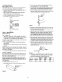
3. On one end, make a saw cut approx'_mately l/,s" deep on
each diagonal line. This is for the spur center.
Refer to Figures 5 and 42.
CAUTION:
Make sure the power cord is removed from the
outlet before attempting to change the belt post_on.
4, The other end uses the bearing center. Place the point of the
beating center on the wood where the _agonal lines cross.
5. Drive the bearing center into the wood, Use a wooden
mstlet or a plastic hammer, but put a piece of wood on the
end of the bearing center to protect it from harm.
Remove socket head bolt and open pultey cover (Fig. 42,
Key Nos. t5 and 16).
Refer to F3gure 5 for desired epthdle speed. Lift belt to
required pulley step on the spindle pulley.
Li_ belt to required pulley step on the motor pulley.
Close pulley cover and secure with bolt.
ASC
SpindlePulley
f
- 3000 RPM
B2 - 2000 RPM
C3 - 1300 RPM
Figure 7
6. Remove the beadng center and drive the spur center into
the other end of the wood. Make sure the spura are in the
saw cuts. Remove the spur center.
Motor Pulley
123
Figure 5 - Spindle Speeds
ON/OFF
7. Make sure the centers and the hole in the spindle and the
tailstock quill are clean. Insert the spur center into the
headstock and the bearing center into the tel]stock. Tap
them in lightly with a piece of wood. Do not drive them in.
8. Place the wood between the centers and lock the tailstock,
SWITCH
Refer to Figure 42.
-
The ON/OFF switch (Key No. 29) is located on the front of
the rathe bed, To turn lathe ON, pull switch to the up position.
To turn lathe OFF, push switch to the down pceitic)n.
9. Move the beating center into the wocd by turning the hand
wheel Make sure that the bearthg center and spur center
are =seated" into the wood in the holes made in steps 5 and
6. Rotate the wood by hand while turning the hand wheel.
The lathe can be locked from unauthorized use by locking the
switch, To lock the switch:
•
10. Adjust the tool rest approximately 1,t,"away from the corners of the wood and V," above the center llne. Note the
angled position of the tool rest base. Lock the tool rest
base and thetool rest.
Turn the switch to OFF positionand disconnect lathe from
power
•
V
source.
Pull the key out. The switch cannot be 0Jrnedon with the key
removed.
NOTE: Should the key be removed from the switch at the ON
position, the switch can be turned to OFF position, but cannot
be turned to ON position,
•
To replace key, slide key into the slot on switchuntil it snaps.
SPINDLE
TOOL
REST
TURNING
Figure 8
11. Observe the speed chart. Move the V-belt on the pulleys
to the slowest speed, Rotate the wood by hand to make
sure that the corners do not s_ike the tcol rest_
If y_u have never done any amount of wood turning, we suggest that you prac'dce using the various wood turning tools.
Start with a small spindle turning.
Be sure to study the following pages of this manual They
explain and iIlusthate the correct use of the turning tools, the
positioning of the tool rest, and other information to help you
gain experience.
1. Select a piece of wood _/_"x 1/_,x 4".
2. Draw diagonal lines on each end to locate the centers,
Diagonal Unes on
Both Ends
Figure
wOOD
6
6
SQUARE
LENGTH
ROUGH
RPM
FINISH
RPM
SAND
RPM
upto 1"
1" to 3"
1 to 12"
1 to 12"
1350
2250
2250
3500
3500
3500
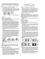
USING WOODWORKING
When You Can Cut and When You Must Scrape
There are two different approaches:
CHISELS
SELECTION OF CHISELS
Sharp tools are essential for clean, easy work. Select tools that
will
takeand holdkeen edges.
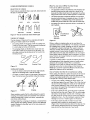
GOUGE
SKEW
nd
SPEAR POINT
Figure
g -The
PARTING
Six Commonly
ROUND
Used Chisel
•
The second approach is toward the diameter of a workpiece
(as when turning the face of a facaplate turning, or the side of
a large shoulderon a spindle turning). In this approach, the
surface being turned rotates like a disc under the chisel edge.
•
Sometimes the optimum approach will be a combination of
both methods.
TOOL
f14
FLATNI_E
• One approach is toward a drcumfarence of the workplace (br
example turning down the outer surface of a cylinder or the
inner wall of a hollow round box), In this approach, the surface
being turned l_-avelsunder the chisel edge like an endless bell
t
; 272
NOSE
Types
onoa
Diameter
Approach
THEORY OF TURNING
The two classes of chisels are those intended primarily for
cutting, end chisels used only for scraping.
Figure 12
•
Either e cutting or scraping action can be used when the
approach is toward a circumference -the shavingis removed
like a peeling from a potato, Scraping can only be used when
the approach is toward a diameter. The reason is obvious
when you consider that faceplate turning practically always
requires removal of wood across the grain. Wood does not
peel easily across the grain and attempts to use any inappropriate cutting methods will fiksiy result in damage to the workpiece. There is also danger that the tool could be pulled from
the hands of the operator.
The cutting chisels are the gouge, skew and parting tool.
These are the most used. They are commonly sharpened
to a razor edge by honing on both sides.
The scraping chisels ere the f_at nose, round nose and
spear point. These are not honed on the f_atsides - the
wire edges produced by grinding ere lef_ on to aid in the
scraping process.
Cutting
Figure
Chisel
Scraping
Chisel
10
Cutting and Scraping
To cut, the chisel is held so that the sharp edge actually
digs into the revolving work to peel off shavings.
To scrape, the chisel is held at a right angle to the work surface. This tool removes fine particles instead of shavings.
In general, a cutting action is used for the majority of spindle
turning operations while faceplate turning is usually accomplished by the scraping method. When a combination
approach is to be used, the operator will have to judge, by the
feel of the work, when to stop cutting and start scraping.
Never try to cut when it becomes difficult to hold the chisel
against the roughness of the wood grain.
How to Position Tool Rest for Circumference Cutting
When cutting, the object is to pierce the outer skin of wood to
a certain desired depth and then to hold the chisel steady
with the bevel edge parallel to the work circumference so that
it will peel off a shaving at this desired depth.
•
Figure 11
Cutting
Scraping
Many operations require that the cutting chisels be used for
scraping, but scraping chisels are practically never used for
cutting. Scraping dulls a chisel much faster, especially the
razor sharp cutting chisels.
Cutting is faster than scraping end produces a smoother finish
which requires less_sanding. However, it is far more difficult to
master. Scraping, on the other hand, is far more precise and
easier to control
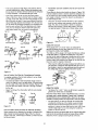
The only sure method of holding the chisel steady is to
rest the bevel against the work (Figure 13A). When the tool
rest is at the proper height, the chisel can be held with the
bevel pressed against the work, and the tool rest will act
as a fulcrum to support the chisel against the downward
force of the revolving work.
If the rest is placed too low, so that the chisel is held with
the bevel out from the work (Figure 13B), the cutting edge
will continue to dig deeper into the work. It will dig in until
the "bite" becomes so deep that your hands have diMcuffy
holding the chisel - then the improperly supported chisel
will begin to bounce or chatter against the workpiece.
ff the rest is placed too low, the chisel must be held
extremely high to position the bevel against the work
(Figure 13C). Then the rest loses most of its value as a fulcrum and the downward force of therevolving workpiece
tends to kick the chisel back out of your hands.
If the rest is placed too high (Figure
• Alldiameter approach operations must be done at the left
of center.
13D) and the chisel is
corre_y
positioned for cutting, it strikes the workpiece near
the top where the direction of fome exerted bythe workpiece
is neady horizontal
If the rest is placed
- and kickback
Three different chisel contact points are shown in Figure 15B.
It will be noted that when a chisel i_ above the work.piece center (or below it) the work surface sweeps past the chisel edge
at an angle and tends to carry the chisel in one direction or
the other along the rest.
will again result.
too far out from the work surface
(Figure 13E), then, when con'ectiy held, the chisel is again
too high on the work. Also, you have lees leverage on your
aide of the tool rest and it is even more difficult to hold the
chisel. With
large diameter
work
can be above the workpiece
(Figure
centerline,
Only when the chisel contacts the work on the centerline,
doe_ the work surface pass squarely under the chisel
edge. This, then, is the position in which it is easiest to
hold the chisel steady. To obtain this position, place the
rest approximately %" (thickness of chisel) below center.
'13F), the tool rest
and somewhat
out
from the work surface. With small diameter work (Figure
13G), the rest should be ¢_oser to the work surface. As
work grows
smaller,
Fie. 13A
the rest should
be repositioned.
Fig. '_3a
Fig. 15A
Fig. '13C
Fig. 15B
No ._u_port
_,_,J D_
Bell
_haller
6
t j'
I:=oirll
Rest
Ch_]
CLlt_ri_
PtOp_T_
Ch_e
I T_
Hor_Dr)_l
_
Figure 15
TO 0 H_h
USING THE
Fig. 13E
GOUGE
Three gouges, the V,, % and 3/," sizes, are adequate for
general homeshop turning, Other sizes _-om % to 2" can be
purchased to provide more flexibility.
The chief use of the gouge is for rough circumference cutting
of raw etock down to a cylinder of working size. It is best to
use this tool for rapid cutting away of large areas of the workpiece. When the tool is used this way, it does not produce a
smooth surface.With practice, the gouge can be used for cutting coves and the shaping of long cuts.
When used for cutting, the gouge is alwaysheld with the convex side do_,n. It should be rolled approx,imatety 30_ to 45° in
the direc_
in which it is being advanced along the rest and
the cut_ng edge should be elightly ahead of the handle.
Cutting Edge
Advanced
Wrong
How to Position Tool Rest for Circumference Scrapmg
In scraping operations, the tool rest position is not as critical
as it is for cutting operations.
•
The chisel generally is held horizontally, though it car] be
held at an angle to reach into tight places. Considering that
thewire edge of thechisel does the scraping, Figures 14B
and 14C show the results of too tow or too high a position
for the reel
Figure 16
USING THE SKEW
Figure 14A shows the chisel action with therest correctly
positioned.
Fig. 14A
Fig. 14B
Right
-
Fig. 14C
Two skews, the '/_
and 1" sizes, are all that are needed for
general use. Other sizes are available.
This ted is nearly always used to make finishedcuts,to cut vees
and bead_, and to square shoulders. Propedy used, it produces
the best _nish that can be obtainedwith a chisel. It is not recommended for scraping because the edge tends to dull more quickJy.
For finish cutting, the skew is held with the cutting edge
considerably in advance of the handle, bevel side down.
Keep the base of the bevel against the work. It is good
practice is to place the skew well over the work, pull it back
until the edge begins to cut, then swing the handle into
position to advance the cut.
Figure 14
How to Position
Chisel and Rest for Diameter Scraping
When scraping on the diameter, that portion of surface to the
right of center is moving upward (Figure 15A). If a chisel is
placed in this area, it will simply be carried up off the rest and
out of your hands.
Both the toe and the heel of the skew can be used for takinglight
cuts, but do not peneb'ate the wood too deeply wi_out cutting
clearances. There is dangerofburningthetip of the tool,
8
•
The holder should pray'tale s shoulder against which the
butt end of the knife can be firmly seated.The knife must
be securely mounted, either by means of a screw threaded
into the ho_der, or by compressing it between two prongs
bolted together.
Figure 20
_
_
Figure 17
USING THE PARTING TOOL
USING A BLOCK PLANE
The parting fool has just one primary purpose: to cut into the
workplace as deeply as desired, or all the way through to
make a cut-off. It is, therefore, a very narrow tool ('6" wide)
and shaped to cut its own clearance so that be edge wil! not
be burned. When used for scraping, however, the parting tool
should be backed off regularly to prevent overheating.
Clear, glass-smooth finishes (especially on softwoods) can be
obtained by using a block plane set to take a fine shaving.
• The tool rest should be raised up approximately to the top
of the workplace - and the plane should be horlzontal, but
turned slightly in the direction of travel so that it will take s
shearing cut,
Unlike the gouge and skew, the parfing tcol is seldom held
with the bowl against the work. Since the amount of stock
removal is small, a support for the bevel is not necessary
•
Two tool rests, one in frontand the other behind the work, can
be used to advantage in positioning the plane so as to exactly
1imitthe depth of cut (and finished size of the work.piece).
The tool is simply fed into the work at an angle (for cutting), or
pointed at the workpiece center (for scraping). It can be held
easily in one hand.
Cutting
Scraping
4--,,
Figure 21
USING WOOD
A I/Z wide spear point chisel, a _h"wide round nose chisef,
and a 1" wide fiat nose chisel complete the list of tools
ordinarily used by craftsmen and hobbyists.
Each of these scraping chisels can be purchased in various
other sizes for special purposes. AJf are very usefof for diameter scraping operations and for circumference scraping when
cutting methods cannot be employed.
•
The spear point is used for fine scraping and delicate operations such as the forming of beads, parallel gram/as and
shallow yeas.
•
Edges and bowl contours can be rounded with the round
nose chisel.
FILES
A wood rasp will remove stock quickly when held against
the revolving wcrkpiece. Care should be taken to support
the rasp firmly against the tool rest. An improperly held
rasp, when used on a rough surface, can kick back and
caus e operator injury.
•
The rasp will leave a very rough finish.
•
Finer finishes (similar to those produced by scraping) can
be obtained by using files in the same manner. Various
types of files can be used for shaping vees, beads, coves,
etc. If pressed too hard into the wood, soma files can burn
the workplace.
USING THE SCRAPING CHISELS
•
RASPS AND
•
Keep the file clean to keep it cutting uniformly, Files work
best on hardwoods.
Any fiat surface can be scraped with the fiat nose chisel.
Figure 22
HAND POSITIONS
Spear
Point
Round
Nose
When using any of the chisels, the hand takes a natural position
on the tool handle.This pos_on may be near the middle of the
handle or towards the end, depending upon the amount of
leverage required. The position of the hand near the tool rest is a
matter of individual preference, but there are three generally
accepted positions, each best for certain types of operations.
Fiat nose
Figure lg
USING SHAPER OR MOULDING KNIVES
An old chisel can be made to serve as a holder for shaper
or moulding knives.
Such knives make it possible to scrape many interesting
shapes intothe workpiece surface using one or two operations
instead of the many operations required with standard chisels.
It is generally not practical to use cut_ng methods with special
shape tools.Scraping methods should be used instead.
9
MAKING STANDARD CUTS
Roughing Off
Roughing off and other heavy work requires a firm grip and
solid positioning of the chisel against the rest. This is best
obtained by the tool-rest hand positioned illustrated, The wrist
is dropped down so that the heel of the hand below the little
finger acts as a sliding guide against the rest The handle
hand controls chisel position.
,THE ROUGHING OFF-CUT
Reducing a square orodd shaped workplace down to a cylinder of approximate size for finish turning is called "roughing
off". Faceplate turnings and large diameter spindles should
first be partly reduoed by sawing, but small spindles are easily
turned down entirely with the large (el,.) gouge.
• Start the first cut about 1" from tailsfock end - then run it
toward the ta_stock and off the end of the workpieca.
Next. start another cut 1" nearer the headstock- and run it
back towards the tailstock, to merge with the firsl cut.
•
Figure 23
•
Continue cutting in this manner until 1 to 2" from the headstock is left uncut. Reverse the direction of tool travel and
work one or two cuts in succession toward theheadstock
and off this end of the workplace.
•
Never start a cut directly at the end - if the chisel catches
the end, it will damage the workplace.
•
Never take tong cuts while corners remain on the work, as
this tends to tear long sliversfTom the corners.
•
The first sedan of cuts should not be too deep. It is better
to partially reduce the work to a c!lieder all along its
length. After that, start a second series of cuts to complete
reducing it to a cylinder.
•
Once a cylinder has been formed, step lathe up to next
faster speed. Further reductions in size can now be
accomplished by cutting as deeply as desired at any spot
along the work. At this stage, long cuts san be made from
the center to either end.
Finish Cut@ng
Finish cuing requires more contro_ - with less force. Finish
cutting is better done with the palm of the tool-rest hand
turned up.The wdst is still held down, and the side of the
index finger acts as a guide along the rest In this position,
control of the chisel is shared by both hands. The fingers of
the tool-rest hand are free to assist in positioning the too[.
Figure 24
Intricate Cutting
Intricate, delicate cutting requires extreme control with prsddcalty no force. This is best accomplished by guiding the chisel
with the fingers of the tool-rest hand. The hand is held palm up
with the vcdst high. The little finger is placed against the rest to
steady the hand, The chisel does not touch the rest and the
handle hand is completely secondary to the food-rest hand.
Generally, roughing off is continued until the cylinder is
approximately V." larger than the desired finished size.
Roundness cen be tested by laying the gouge on top of
the work - it will not ride up and down when cytinder is
perfectly round.
NOTE: The first and second positions are equally good for
scraping operations, but the third position is practically never
used for scraping.
Figure 27
Figure 25
Testing Roundness
"
ROUGH-CUTTING TO SIZE
The roughing-off cut can be made to acouratefy size the cylinder to e g'rcen diameter.
Cuffing to Depth
Many scraping operations and cutting to depth with the parting tc_4 can be easily accomplished with the one hand. The
chisel is grasped firmly with theindex finger on top to press it
down against the reel It is thrust straight into the work.
Holding the tool in this manner leaves the other hand free to
hold a pattern or calipers, etc., to check work in progress.
Another method is to make a number of sizing cuts at intervals along the work, then use the gouge to reduce the whole
cyfinder down to the diameter indicated by these cuts.
MAKING SIZING CUTS
Sizing cuts are useful to establish approximate finished size
diameters at various points along a workplace. The work can
then be turned down to the diameters indicated and be ready
for finishing.
•
Figure 26
•
10
Diameters for sizing cuts should be planned to be about 1/_,,
greater than the desired finish diameters. A sizing cut is
made with the parting too[.
Hold the tool in one hand, and use the other hand to hold
an outside caliper preset to the desired sizing-cut diameter.
/ks the cut nears completion, lower the chisel point more
and more into a scraping position.
When the calipers slip over the workpiece at the bottom of
the groove, then the cut is finished.
Wrong
Right
Figure 28
SMOOTHING A CYUNDER
Figure 30
The final _/_"can be removed in two ways. Either use the 1"
skew, working from the center toward both ends and taking
lighter and lighter cuts until finished, or use a block plane as
illustrated in Figure 21.
CU]q-ING
CUTTING VEES
Vee grooves
When the toe is used, the cutting action is exactly the
same as when trimming a shoulder except that the skew is
tilted to cut at the required bevel Light cuts should be
A SHOULDER
A shoulder can be the side of a square portion left in the
workpieca, the side of a turned section, or the end of the
workpieca. Most shoulders are perpendicular to the work axis,
but a shoulder can be at any ang}e.
taken on first one side and then the other, gradually
enlarging the yea to the required depth and width.
When the heel is used, the skew is rotated
Second, make a sizing cut with the parting tod, plating
this cut about %," outside the shoulder position and cutting
b within about '/="of the depth desired for the area outside
of the shoulder.
is shaltow,
down into the
work, using the rest as a pivot. Otherwise,
cutting position
and sequence of cuts are the same./ks when using the
toe, it is important that cutting be done only by extreme
First, mark position of the shoulder with a pencil held to
the revolving workpiece.
If shoulder
can be cut with either the toe or heel of the skew.
end of cutting
edge,
If deep vees are planned,
making
Vees can also be scraped
three-sided file.
the toe of the skew can be used to
make the sizing cut. Do not go in deeper than _/," with the
skew unless wider and wider yeas are cut to provide clearance for this too!.
Jr'is quicker
to start them by
a sizing cut at the center of each yea.
with the spear point chisel or a
Figure 31
CUTTING BEADS
This operation
Figure 29
requires
considerable
practice.
•
First, make a pencil line to locate
of two or more adjoining beads,
the tops (highest
•
Then, make a yea groove at the exact center between
points)
two
Use the gouge to remove any waste stock outside of shoulder. Smooth this section, up to within '/="of shoulder, in the
usual manner. Finishing of the shoulder, unless it is more
than 1" high, is best done with the V_"skew,
lines and down to the desired depth of the separation
between the beads. Be careful not to make the groove too
wide or you will remove portions of the desired beads. The
•
The toe of the skew is used to remove the shavings from
the side of the shoulder - down to finished size.
the skew. Use a Vz"skew, unless beads are very large.
•
Hold skew so the bottom edge of bevel next to the shoutder will be very nearly parallel to side of shoulder - but
with cutting edge turned away at the top so that only the
extreme toe will do the cutting, if cutting edge is fiat
against shoulder, the chisel will run.
•
£tart with handle low, and raise handle to advance toe into
the work.
•
Cut down to finished diameter of outside area. Then, dean
out the corner by advancing heel of the skew into it along
the surface of the outside area,
•
sides of the two adjcining
•
beads are now cut with the heel of
Place skew at right angles with the work a.,ds, f_at against the
surface, and well up near the top. The extreme heel should
be just inside the pencil line that marks the top of the bead.
•
Now, draw skew
straight
back while
raising
handle
slowly - until edge of the heel at the pencil line starts to
cut.
• As edge begina to cut, roll skew in the direction of the vee
so that the exact portion of the edge which started cutting
will travel in a 90° arc down to bottom of the vee.
•
Upon reaching bottom of the yea, the skew should be on edge.
•
Reverse the movements to cut side of the adjacent bead.
Tilt the cutting edge, with handle raised up so that only the
extreme heel does this cutting.
If shoulder is at end of work, the process is called squaring
the end. In this case, reduce outer portion to a diameter
about '/4"larger than tool canter diameter.Then, later, sew
_Swing
off the waste stock.
Figure 32 - Cutting Beads
11
Tool
t is important that only the extreme heel should do the ¢ut:ing. This means that the bottom edge of the bevel next to the
cee must at all times be tangent to the arc of the bead being
formed.
Easier beads can be ehaped with the spear point chisel.
•
Figure 35 - Chisel Inclined in Direction
Use pencil marks and sizing cuts as before.
Push the chisel stzaight into each cut and rotate horizontally to round oft the adjacent edges. It must be moved slightly in the direction of rotation at the same time to keep the
point from digging into the adjacent bead.
of Cut
If gouge is used, make cut in the same direction. Start with
the handle well back o# point - _,vinging handle in the
direction of tool travel to overtake the point, if necessary,
when the steep part of the curve is reached. Object is to
have the extzeme point doing the cutting throughout with
the bevel as tangent to curve as possible.
MAKING LONG TAPER CUTS
Start
Long taper cuts are made like long convex cuts, with theskew
or gouge. However, the angle between the cutting edge and
handle is kept constant dudng the entire cut The handle is
not swung around.
Finish
Figure 33
Always cut downhill. Do not cut too deeply at the center of
the taper.
CLrFI-ING COVES (CONCAVES)
This is the most difficult single cut to master - but one of the
most important in good wood turning.
• First, use pencil marks to indicate the edges.
•
•
SPINDLE TURNINGS
PLO'FRNG THE SHAPE
Then, rough out the cove, to within about 1/_,of the desired finished surface, by scrapingwith the gouge or round nose chisel. tfthe cove is to be very'wide, sizing cuts can be made to
plot the roughing out. Once it is roughed out, _e covecan be
finished in two cuts, one from each side to the bottom canter.
Once the basic cuts have been mastered, you are ready to
turn out finished work.
The first step is to prepare a plan f_r the proposed turning.
This can be laid out on a suitable sheet of paper. The layout should be to full size.
At the start of either cut, gouge is held with handle high
and the two sides of blade held between the thumb and
forefinger of tool rest hand, just behind the be/at.
Next, prepare the turning stockby squadng it up to the
size of the largest square or round section in your plan.
The stock can be cut to the exact length of the proposed
turning. However, in most casee, it is best to leave the
stock a little long at one or both ends to allow for trimming.
Mount the stock in the lathe and rough it offto a maximumsize cylinder.
Now, project your plan onto the turning by pencil marking
the various critical dimensions along the length of the spindle. These dimensions can be laid out with an ordinary
ruler or by using a template. Make the pencil marks about
'/2" long so they will be visible when the work is revolved
under power. The lines can be quickly traced around the
spindle by touching each line with the pencil.
Diameters
11/,"
2" 11k." 2_L"1_I,"1%"2_A,"
1=1,'1fl¢1_1_'1"
Position the fingers so that they are ready to roll the blade
into cove.
Hold blades so that bevel is at 90_ angle to the work axis
with point touching the pencil line and pointed intowork axis.
From this start, depress poir_t sfighfiy to start cut, then continue to move point down in an are toward the bottom center cove - at the same time rolling chisel uniformly so that,
at the end of the cut, it will be fiat at the bottom of the
cove.The o_Ject is to keep the extJ'eme point of gouge
doing the cutting trom start to finish. Reverse these movements to cu! the opposite side.
Penci Mark
FigLire
S_Jng Cuts
34
Coves also can be scraped to finish using the round nose
chisel or a rattail file, These methods do not generally produce perfectly curved coves.
MA_NG
•
....
__
Figure 36
• After marking, use the parting tool to make sizing cuts at
all of the important shoulders. When learning, you will find
it best to make sizing cuts to accurately p!ot the various
diameters. Experienced wood workers can manage with
fewer such cuts at the important shoulders.
LONG CONVEX CUTS
First, turn work down to approximate size, using sizing cuts
(as required) to determine various diameters. Finish cuts
can then be made with either skew or gouge.
If the skew is used, the principles of the operation are the
same as those employed in cutting a bead - except that
the curve is longer and may be irregular. Use the extreme
heel throughout - start at longer end of curve (if curve is
irregular) and progress toward steeper end.
•
12
Plan each sizing cut so that it is in waste stock and make
each cut deep enough so that there will be just enough
wood left under the cut for the finishing process.
•
Once the sizingcute have been completed, rough-out the
excess wood with a gouge• Then, proceed with the finishing process by making the various types of cuts required.
FACEPLATE AND CHUCK TURNINGS
PLANNING THE WORK
Figure 39
Make a layout first,.to provide a visual pattern to follow while
working the turning. Pattern can be taid out in the same manner as epindie patterns - or templates can be made which
can be held against the work for visual comparison. Circles to
IDeate the various critical points (at which the contours of the
faceplate take distinct form) can be quickly scribed on the
rotating work by using the dividers.
The applicatlon of the sandpaper strip is shown in the illustrations.
•
Care must be exercised in order to prevent dubbing the
corners of beads, shculders, etc.
It is good practice to finish sanding with the work in
reverse rotation (remount work exchanging end for end).
This is particularly true when sanding basswood, white
pine and mahogany. These woods are hard to sand clean
since sanding packs the surface fuzz down to the wood.
Sanding very lightly,and not too long, with the lathe
reversed, will lift the fibers and cut them off clean.
Figure 37
PLANNING VARIOUS CUTS
The circumference of a faceplate turning is Foughed-out and
finished in the same manner that a spindle is worked.
Pra_cally all of the balance of the operations, however, are
done by using scraping methods. A few of the standard contours which must often be tuned are illustrated in the accompanying sketch which also shows the proper chisels for shaping these contours. Any roughing out to depth is generally
accomplished with the gouge held in the scraping position.
Wood Fibers
Sandpaper
-_bers Lifted and Cut Off
Use of Template
Square
Nose
Round
Nose
Figure 40
INSTALLING
THE PEN MANDREL
Refer to Figures 41 and 42.
Remove spur center (Fig. 42, Key No. 2) from spindle (Fig.
42, Key No. 3).
Measuring
Depth
•
Thread shaft (B) securely into tapered sleeve (A).
Slide workpiece and bushings (C) onto the shaft, Use an
appropriate number of bushings so that workpieca will be
held securely,
Figure 38
SANDING, BUFFING AND POLISHING
• Secure workpieca and bushings using knutied nut (D).
USINGTHE
•
Insert the tapered sleeve of the mandrel firmly into the
spindle.
•
Use beating center (Fig. 42, Key No. 41) to support shaft
end of the mandrel.
•
•*
•
LATHE TO SANDTURNINGS
Turnings should be sanded with the lathe running in
highest speed.
A large sheet of sandpaper is useful for smoothing cylinders.
All o_er sanding operations are done with a narrow strip
of abrasive paper. The best finishing grit is 3/0 for softwood, 4/0 for hardwoods. Worn 2/0 paper is often used,
and is the equivalent of 3/0 or 410 new papec
Figure 41
13
C
WARNING:
Make certain that the unit is disconnected from
power source before attempting to service or remove any
c6mponenL
CLEANING
Keep machine and workshop clean. Do not allow sawdust to
accumulate on the tool. Keep centers clean. Check inside belt
guard to make sure that saw dust has not accumulated.
Be certain motor is kept clean end is frequentJy vacuumed
free of dusL
Use soap and water to dean painted parts, rubber parts and
plastic guards.
LUBRICATION
The shielded ball b_adngs in this tool are permanently lubricated at the factory They require no further lubrication.
KEEP TOOL IN REPAIR
If power cord is worn, cut, or damaged in any way, have it
replaced immediately,
Replace any damaged or miasing parts. Use parts list to
order parts.
Any attempt to repair motor may create a hazard unless
repair is done by a qualified service technician. Repair service
is available at your nearest Sears store.
14
_YMPTOM
POSSIBLE CAUSE(S)
CORRECTIVE ACTION
vlotor will not start
!. Low voltage
2. Open circuit in motor or loose
connections •
1. Check power line for proper voltage
2. Inspect all lead connections on motor
for loose or open connection
_otor will not start; fuses blown or circuit
_reakers are tripped
1. Shor_ circuit in line cord or plug
1,
2. Short circuit in motor
connections
2. Inspect al! lead connections on motor
for loose or shorted terrninals or
worn insulation on wires
3. Install correct fuses or circuit breakers
or loose
3. incorrectfuses or circuit breakers
in power line
_otor falls to develop full power (power
)utput of motor decreases rapidly with
Jecrease in voltage at motor terminals)
1. Power line ovedoaded with lights,
app]icances and other motors
2. Undersize wires or circuits too long
Inspect line cord or plug for damaged
insulation and shorted wires
1. Reduce the load on the power iine
3. General overloading of power
company's facilities
2. Increase wire sizes or reduce length
of wiring
3. Request a voltage check from the
power company
vlotor overheats
Motor overloaded
Reduce load on motor
_otor stalls (resulting in blown fuses or
ripped circuit breakers
1, Short circuit in motor or loose
connections
1. Inspect connections
in motor for
loose or shorted terminals or
worn insulation on lead wires
2. Low voltage
3. Incorrect fuses
2. Oorrect
or circuit breakers
3. Install
the tow line voltage
correct fuses
conditions
or circuit breakers
in power line
4. Motor overloaded
4. Reduce load on motor
Vlachine slows down while operating
Applying too much pressure to workpiece
Ease up on pressure
Foot "chatters" during turning operation
1. Workpieee is too far out-of-round
I True up the roundness of the
2. Workpiece
2. Establish new center
to reduce wobble
workpiece
3. Operator
Norkpiece splits or "breaks up" during
:urning operation
has too much wobble
using bad technique
before
turning
operation
marks on ends
3. Read instructions
and take lighter
to minimize chatter
cut_
4. Cutting motion is against the grain _.f
the workpiece
5. Workpiece is too long and thin workpiece is deflected by tc,¢_pressure
4. Use cutting
Workpiece contained defects before
mounting
Select or assemb]e a workpiece that is
free of defects
15
motion
that is with
the grain
5. Install a steady rest in the middle,
behind the workpiece
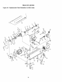
Model
351.221060
Figure 42 - Replacement Parts Illustration for Mini Lathe
5O
5
4
\
8
12
14
4
15
\
52
_-
L "-..
51
ss...
--"_""_.
33
'1
21
31
20
30
12
28
v
~25
16
KEY
NO.
1
PART NO.
22964.00
DESCRIPTION
Face Plate
2
3
23018,00
#1MT Spur Center
22993.00
4
STD863506
22982.00
Spindle
5-0.6 X 6ram Pan Head Screw*
5
6
STD315225
Headstock Cover
KEY
NO.
27
28
QTY
1
1
PART NO.
22996,00
NIA
DESCRIPTION
5-1.0ram Square Nut
Bed
QTY.
4
1
1
16
29
16080. O0
Switch
1
30
22999.00
Bed Cover
1
1
31
23000.00
Strain Relief
1
2
1
32
33
23001.00
22979.00
Line Cord
Plate
1
3
7
22981,00
6202z.z Ball Bearing*
Headstock
8
STD833020
6-1.0 x 20ram Hex Head Bolt*
2
34
22985.00
6-1.0 x 10ram Handle
2
9
ST0851006
6ram Flat Washer*
5
10
06369.00
Clamping Bracket
5-1.0 x 6mm Set Screw
1
1
00533.00
37
09845.00
3CMI-6 E-Ring
1
12
01210.00
1
1
2
22992.00
00964.00
11
3 x 10ram Spring Pin
3AMI-Retaining Ring
5-0.8 x 5ram Set Screw
35
36
13
22980.00
Tool Rest Assembly
Tool Rest Base
1
1
22977.00
1
1
22987.00
22966.00
14
Spindle Pulley
Drive Belt
38
39
40
22991.00
Locking Bar
1
15
16
22976,00
21634.00
Pulley Cover
6-1.0 x 55turn Socket Head Bolt
1
1
17
22976.00
#1MT Bearinq Center
QuiU
Tailstock
1
1
1
STD863510
1
4
23019.00
22969.00
22988.00
18
Motor Pulley
5-0.8 x 10mm Pan HeadScrew*
41
42
43
44
22995.00
Adjustment Nut
1
19
Z3157.00
4-0.7 x 130ram Pan Head Screw
1
2O
23002.00
22975.00
Motor Bracket
1
45
46
22997.00
22990.00
Guard Support
6-1.0 x 15ram Handle
1
1
Motor Assembly
1
47
STD851005
5mm Flat Washer*
1
46
22998.00
Guard
1
Capacitor Mount
1
49
ST0644610
6-1.0ram Wing Nut"
!
21
(incl. Key Nos. 4, 22 and 23)
22
22994.00
23
22993.00
24
23003,00
Capacitor
Switch Cord
1
1
50
51
23133.00
ST0640508
Pen Mandrel Assembiy
5-0.6rnm Hex Nut*
1
3
25
STD663612
6-1.0 x 12ram Hex Head Bolt*
5
52
23173.00
Hinge
1
26
22974,00
Mounting Plate
2
&
23139.00
Operator's Manual
1
Standard hardware item available locally
N/A Not available as replacement part
Z_ Not Shown
Recommended
A
17
Accessories
Turning Tools - 3 Piece Set
Model
9-29818
No.
NOTES
18
NOTES
19
Your
Home
For the replacement parts, accessories and
owner's manuals that you need to do-it-yourself.
For Sears
professional
and
like garage
items
installation
door
of home
openers
1-800-4-MY-HOME
Call anytime,
_
appliances
and Water
heaters.
(1-8004694663)
day or night (U.S.A. and Canada)
www.sear_.cor'N
"o_/ww.s_a
rs. ca
Our Home
_
For
repair
of carry-in
and electronics,
items
like vacuums,
call or go on-line
Sears
Parts
lawn
for the location
& Repair
equipment,
of your
nearest
Center.
1-800-488-1222
Call anytime, day or night (U.S.A. only)
www.sears.coiTi
To purchase
a protection
or maint_._ance agreement
1-800
827-6655
(Canada)on
(U.S.A.).
1-888-SU-HOGAR
Trademark
/
Trademark
!
Servi_e
de cornmeme / =D Marque
depos6e
(Canada)
Au Canada pour service en fran£_ais:
1-800-LE-FOYER "c
(1-800-533-6937)
Sears
Mark of Seam,
® Mama Reg_strada 1TM Mama de F6bdca / sM Marca de Servicio
Me Marque
a product serviced by Sears:
s_
(1-888-784-6427)
(U.S.A.)
, -800-361-6665
Pard pedir servicio de reparacion
a domicilio, y pard ordenar plazas:
® Registered
agreement
www.sears.ca
Rc,ebuck and Co.
de Seam. Roebuck
de Sears, Roebuck and CD.
and Co.
© Sears, Roebuck and Co.