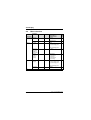
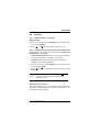
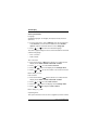
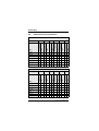
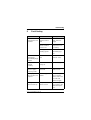
1
Users Instructions and
Customer Care Guide
R 30/35/40 HE combi plus Condensing boiler
6 720 610 598 - 00.2O
6 720 610 598 GB (03.11) TD
ZWBR 7-30 R 30 GC-Number: 47 311 79
ZWBR 11-35 R 35 GC-Number: 47 311 80
ZWBR 11-40 R 40 GC-Number: 47 311 81
Contents
Contents
Excellence comes as standard
4
Safety precautions
5
1
General notes
7
2
Controls
11
3
3.1
3.2
3.3
3.4
3.5
3.6
3.7
3.8
3.9
Operating the Appliance
Preparation
Switching the Appliance On/Off
Switching on the Central Heating
Controlling Central Heating
Combination Boilers: Setting Hot Water Temperature
System boiler with Storage Tank
Summer Mode, Hot Water Only (Combi Appliances)
Frost protection (Combi Appliances)
Fault Condition
12
12
14
15
15
16
17
18
19
19
4
4.1
4.2
4.2.1
4.2.2
4.3
4.4
4.4.1
4.4.2
4.5
Text Display
General Description
Programming
Deleting a setting
Resetting all parameters to their original settings
Menu structure
Setting the time/day
Setting the time and day
Holidays
Heating
20
20
20
23
23
24
25
25
25
27
2
6 720 610 598 GB (03.11)
Contents
4.5.1
4.5.2
4.5.3
4.6
4.6.1
4.6.2
4.7
4.8
4.8.1
4.8.2
4.8.3
4.9
Heating program
27
Setting the Economy temperature (if TR2 is connected) 28
Manual operating mode (if TR2 is not connected)
29
Hot water
30
Hot water program
31
Hot water immediately (System models)
31
i Info
32
Settings
33
Heating (if TR 2 is connected)
33
Hot Water (Storage Tank, System boiler models only) 33
Service
33
Individual timer programmes
36
5
Fault finding
37
6
Tips on saving energy
38
7
General Information
39
8
Maintaining your appliance
40
9
Service
40
10
Fault or breakdown
41
11
Your guarantee
42
12
Guarantee registration
43
13
Operating Instructions Quick Reference
44
6 720 610 598 GB (03.11) TD
3
Excellence comes as standard
Excellence comes as standard
Thank you for purchasing an R 30/R 35/R 40 condensing appliance.
The R 30/R 35/R 40 Series has been developed by the Heat Systems Ltd. Group and the strictest quality control standards are
demanded throughout every stage of production.
Indeed, the Heat Systems Ltd. Group have led the field in innovative appliance design and performance for many years.
The result is that your new R 30/R 35/R 40appliance offers you
the very best of everything – quality, efficiency, economical running costs, proven reliability and value for money.
What’s more, you also have the assurance of our no nonsense
2 year parts and labour guarantee.
And it’s backed up by Worcester Heat Systems Ltd. - Offering a
complete maintenance scheme to keep your boiler operating at
peak condition and efficiency.
No wonder that more and more people are agreeing that when it
is gas, it has to be a Worcester Heat Systems Ltd. Condensing
appliance.
Benchmark
The “Benchmark” initiative is the new code of practice to encourage the correct installation, commissioning and servicing of
domestic central heating boilers and system equipment.
The “log-book” is a vital document that must be completed by the
installer at the time of installation. It confirms that the boiler has
been installed and commissioned according to the manufacturers
instructions.
Without the completion of the “log-book”, manufacturers may
refuse to respond to a call–out from a householder, who will be
advised that he or she must call back the installer, who has not fulfilled his obligations to record the information required by the initiative.
4
6 720 610 598 GB (03.11)
Safety precautions
Safety precautions
Gas Safety (Installation and Use) Regulations 1998
It is the law that all gas appliances are installed by a competent
person in accordance with the above regulations. Failure to install
appliances correctly could lead to prosecution. It is in your interest, and that of safety, to ensure compliance with the law.
If you smell gas:
B Turn off gas service cock at the meter.
B Open all doors and windows.
B Do not operate any electrical switches.
B Do not smoke.
B Extinguish any naked flames.
B Call your gas company.
If you smell fumes from the appliance:
B Switch off appliance.
B Open windows and doors.
B Inform your heating engineer.
Fitting and modifications
B Fitting of the appliance or any modifications to the appliance
may only be carried out by a competent person.
B Flue systems must not be modified in any way.
Maintenance
B We recommend that you take out a maintenance contract
with a competent installer and have the appliance serviced at
regular intervals.
B Ensure that your Service Engineer uses only genuine spare
parts!
6 720 610 598 GB (03.11) TD
5
Safety precautions
Combustible materials
B Do not store or use any combustible materials (paper, thinners, paints etc.) in the vicinity of the appliance.
Health and safety
B This appliance contains no asbestos products.
B There is no potential hazard due to the appliance being electrically unsafe.
B There are no substances used in the construction that are a
potential hazard in relation to the COSHH Regulations (Control of Substances Hazardous to Health Regulations 1988).
Ventilation Air/Ambient Air
B Keep ventilation air/ambient air free of corrosive substances
(e. g. halogenated hydrocarbons which contain chlorine or fluorine compounds). In this way corrosion can be prevented.
6
6 720 610 598 GB (03.11)
General notes
1
General notes
To get the best from your appliance please read these instructions
carefully.
Sealed heating systems
The appliance is fitted to a sealed heating system which is prepressurised. Your installer will tell you of the minimum and maximum pressure which must be indicated on the pressure gauge.
Check regularly that the pressure is maintained and contact your
installer or maintenance engineer if there is a permanent significant drop in the pressure. If the system loses pressure it should
be repressurised and the cause of the fall investigated.
Central heating systems
During the first few hours of operation of the central heating system, check that all radiators are being heated at an even rate. If the
top of a radiator is at a lower temperature than the bottom then it
should be vented by releasing air through the venting screw at the
top of the radiator. Ask your installer to show you how this is done.
Repeated venting will reduce the quantity of water in the system
and this must be replenished for safe and satisfactory operation
of the appliance.
Should water leaks be found in the system or excessive venting is
required then a service engineer must be contacted to inspect the
installation and rectify any fault.
Only additives that are compatible with aluminium may be used in
the system. Any incompatible additive used will invalidate the
guarantee.
Condensate drain
This is a condensing appliance and the terminal will, at times, give
out a plume of water vapour. This is quite normal.
The appliance produces quantities of condense which is discharged regularly through the siphon.
6 720 610 598 GB (03.11) TD
7
General notes
Clearances
Your installer will have provided adequate space around the appliance for safety and servicing access. Do not restrict this space
with the addition of cupboards, shelves etc. next to the appliance.
Left-hand side
Right-hand side
In Front
Above Casing (Vert. Flue)
Above Flue Turret
Below
10 mm
10 mm
600 mm
200 mm
30 mm
200 mm
Table 1
Room thermostat
A room temperature controller may be fitted to control the central
heating. Refer to the instructions supplied with the thermostat for
information of siting and setting.
Cylinder thermostat - System boilers
The cylinder thermostat should be set to 60°C which will be satisfactory for bathing/washing in normal circumstances.
Thermostatic radiator valves
It is recommended that this type of valve is fitted to all the radiators
except one, usually the radiator where the room temperature controller is fitted. They should conform to the requirements of
BS2767:10.
Showers, bidets, taps and mixing valves – Combination
Boilers
Standard hot and cold taps and mixing valves must be suitable for
operating at mains pressure. Thermostatically controlled or pressure equalising shower valves will guard against the flow of water
at too high a temperature.
Hot and cold mains fed water can be supplied directly to an overrim flushing bidet subject to local water company requirements.
8
6 720 610 598 GB (03.11)
General notes
With all mains fed systems the flow of water from individual taps
will vary with the number of outlets operated simultaneously and
the cold water mains supply pressure to the property.
Flow balancing using “ball-o-fix” type valves is recommended to
avoid an excessive reduction in flow to individual outlets.
For further information contact Worcester Heat Systems Ltd.
Technical Services Department.
Hot and cold flow – Combination Boilers
The flow of water demanded from both hot and cold service outlets is dependent upon the mains supply, it may not be possible in
some installations to operate all outlets simultaneously.
Water mains failure – Combination Boilers
If there is a failure of the mains water supply then no water will be
available at a tap or shower until the mains supply is restored. The
appliance will still operate in the central heating mode.
Use in hard water areas – Combination Boilers
In exceptionally hard water areas a device to prevent scale formation may be fitted. Installation of a scale inhibitor assembly should
be in accordance with the requirements of the local water company. An isolating valve should be fitted to allow for servicing.
Alternatively the maximum temperature of the domestic hot water
may be reset to about 45 °C which will reduce the risk of scale
formation in these hard water areas.
Ventilation
This is a room sealed appliance and does not require any air for
combustion from inside the house. If the appliance is fitted into a
cupboard or a compartment is built around the appliance after
installation then the compartment must be separated from the
boiler space by a perforated non-combustible partition as
described in BS 6798.
Notwithstanding the requirements of BS 6798, there is no need
for ventilation openings to be provided in the compartment
because of the low heat loss from the casing.
6 720 610 598 GB (03.11) TD
9
General notes
Do not allow the flue terminal fitted on the outside wall to become
obstructed or damaged.
Pump
The pump is a fully modulating type to which the parameters have
been set by the manufacturer and must not be adjusted.
10
6 720 610 598 GB (03.11)
Controls
2
Controls
136 365 61 317 366 367 363 310 400
ECO
364
8.1
135
295
170
171
172
173
170
6 720 610 598 - 01.2O
Fig. 1
8.1
61
135
136
170
171
172
173
295
310
317
363
364
365
366
367
400
System Pressure gauge
Reset button
Master switch
Central heating temperature control
Service valves in CH flow and return
Hot water
Gas isolation valve (open)
Cold water inlet
Identification sticker
Hot water temperature control
Display
Indicator lamp for “burner on”
Indicator lamp for “off/on”
“Chimney sweep” button
Service button
“ECO” button
Text Display
6 720 610 598 GB (03.11) TD
11
Operating the Appliance
3
Operating the Appliance
3.1
Preparation
Turn on the gas cock (172).
B Press in the handle and turn it anti-clockwise as far as the stop
(when handle is in line with direction of flow, the cock is open).
Central heating system valves (170)
B Using a spanner, turn square nut until groove is in line with
direction of flow (see detail).
Groove at right angles to direction of flow = off.
Cold water inlet valve (173)
B Turn handle so that it is in line with direction of flow.
When handle is at right angles to direction of flow, the valve is
closed.
170
172
173
6 720 610 598-02.2O
Fig. 2
12
6 720 610 598 GB (03.11)
Operating the Appliance
Check the central heating system pressure
B The pointer on the pressure gauge (8.1) should be about 1 bar.
B If the pointer is below 1 bar (when the system is cold), top up
the system with water until the pointer is 1 bar. Your installer
will have shown you how to do this.
B The maximum operating pressure of 2.5 bar at maximum
central heating flow temperature must not be exceeded. If the
pressure increases to 3 bar then the relief valve (15) opens.
2
3
1
4
0
bar
8.1
15
170
171
172
173
170
6 720 610 598 - 03.2O
Fig. 3
6 720 610 598 GB (03.11) TD
13
Operating the Appliance
3.2
Switching the Appliance On/Off
Switching on
B Switch on the appliance at the master switch (I).
The indicator lamp shows green and the display will show the
central heating flow temperature, when the appliance is operating in the central heating mode.
6 720 610 333-04.1O
Fig. 4
i
If the display alternates between -II- and the central heating flow temperature, the trap filling programme is active.
The trap filling programme ensures that the condensation trap is
filled after the appliance has been installed or after the appliance
has been out of use for a long period. For that reason, the appliance remains at minimum heating output for 15 minutes.
Switching off
B Switch off the appliance at the master switch (0).
The green indicator lamp goes out. The optional timer will continue running until the emergency supply is exhausted.
14
6 720 610 598 GB (03.11)
Operating the Appliance
3.3
Switching on the Central Heating
B Turn the central heating temperature control
level:
to the desired
– “Min” setting: 35°C
– Low-temperature heating: setting “E” (approx. 75°C)
– “Max” setting: 88°C
When the burner is lit, the red indicator lamp is illuminated.
6 720 610 333-05.1O
Fig. 5
3.4
Controlling Central Heating
B Set the timer to the correct time.
B Set room thermostat to the desired room temperature.
B Set temperature driven control unit, if fitted. Refer to the
instructions with the control.
B Set the thermostatic radiator valves to the desired settings.
6 720 610 598 GB (03.11) TD
15
Operating the Appliance
3.5
Combination Boilers: Setting the Hot Water
Temperature
Hot water temperature
On combi models, the hot water temperature can be set to
between approx. 40°C and 60°C using the temperature
control
.
The domestic hot water temperature is not shown on the display.
6 720 610 333-07.1O
Fig. 6
Control Setting
Water Temperature
Anti-clockwise limit
approx. 40°C
approx. 55°C
Clockwise limit
approx. 60°C
Table 2
“ECO” button
By pressing and holding the “ECO” button
, until the display
lights, you can switch between Comfort mode and Economy
mode.
Comfort mode: button is not lit (factory setting)
The appliance is held constantly at the set temperature. This
means that hot water is available almost instantaneously at the
tap. Consequently the appliance will switch on at intervals, even if
no hot water is being drawn.
16
6 720 610 598 GB (03.11)
Operating the Appliance
ECO mode with demand detection, button is lit
The demand detection function enables maximum gas and water
economy.
Briefly turning a hot water tap on and then off again signals
demand to the appliance which then heats up the water to the set
temperature.
Hot water is thus available in about 1 minute.
ECO mode, button is lit
Water is not heated up until hot water is drawn. This means that
there is a longer waiting period before hot water is available.
3.6
System boiler with Storage Tank
B Do not set the temperature higher than
60°C for normal operation.
B Only use temperatures of up to 70°C temporarily for thermal disinfection purposes.
i
With the text display you can additional set hot
water charging times or times and temperatures.
B Set the hot water temperature by means of the temperature
control
on the appliance.
6 720 610 333-07.1O
Fig. 7
6 720 610 598 GB (03.11) TD
17
Operating the Appliance
Control Setting
Water Temperature
Anti-clockwise limit
approx. 10°C
(frost protection)
l
approx. 60°C
Clockwise limit
approx. 70°C
Table 3
ECO button
Pressing and holding the ECO button
, until it lights up
switches from Comfort mode to ECO-mode.
Comfort mode, ECO button is not lit (factory setting)
In Comfort mode the hot water tank has priority. The hot water cylinder is first heated up to the set temperature. The appliance then
switches to central heating mode.
ECO mode, button is lit
In ECO mode the appliance switches between central heating
mode and cylinder charging mode every 12 minutes.
3.7
Summer Mode, Hot Water Only
(Combi Appliances)
With room temperature controller
B Turn temperature control
on the appliance anti-clockwise
as far as the stop.
The central heating is now turned off. The hot water function
and the mains power supply for the heating programmer and
timer remain switched on.
18
6 720 610 598 GB (03.11)
Operating the Appliance
3.8
Frost protection (Combi Appliances)
B Leave master switch switched on.
If the appliance is to be left for long periods switch the central
heating on and set the room temperature controller at 6°C.
B Add a suitable anti-freeze fluid to the water in the central heating system.
Suitable products are available from Betz-Dearborn Tel.: 0151
4209563, Fernox Tel.: 01799 550811 and Salamander Tel.:
0121 378 0952.
3.9
Fault Condition
In the unlikely event of a fault occurring while the appliance is in
operation:
The display and the text display then shows a fault code and the
button
may also flash.
If the button
flashes:
B Press and hold the button
until the display shows “– –”.
The appliance will then start up again and the display will show
the central heating flow temperature.
If the button
does not flash:
B Switch the appliance off and then on again at the master
switch.
The appliance will start up again and the central heating flow
temperature will be displayed.
If the fault remains and can not be cleared:
B Call Worcester Heat Systems Ltd. for assistance, giving a
description of the fault and, if possible, the fault code from the
facia display.
6 720 610 598 GB (03.11) TD
19
Text Display
4
Text Display
4.1
General Description
• The text display is used to display information about the appliance and the system and to alter the settings displayed.
• Once the appliance has been in operation for one day, the text
display module has a power buffer period of about 10 hours
during which it will run without the mains power supply. After
that period has elapsed, the clock function shuts down but all
other settings are retained.
4.2
Programming
a
b
c
C
6 720 610 337-08.1R
f
Fig. 8
a
b
c
d
e
f
e
d
Controls
Display
“Up”/“More” button
“Down”/“Less” button
“Back” button
“Next” button
“Delete” button
The standard display shows the following information:
• Time
• Room temperature (if TR 2 connected)
• CH flow temperature
20
6 720 610 598 GB (03.11)
Text Display
• Domestic Hot Water temperature (System boiler if a Storage
Tank is accorded).
Additional indication if a special programme is active:
• x holidays
• Hot water immediately
• Constant on (comfort, if TR2 is not connected)
• Constant off (economy, if TR2 is not connected).
Other special operating modes may be displayed during commissioning, servicing, etc.
The programming procedure is described in detail below using
the clock function as an example:
B To start programming, press any button, e. g.
.
The display lighting switches on and the main menu is displayed:
T
/holidays
6 720 610 598-04.2O
Fig. 9
Main menu
B Use the
or
button to move the cursor arrow on the
left of the menu so that it points to the desired menu item.
In this example, the cursor is positioned next to the menu item
Time/day/holidays.
6 720 610 598 GB (03.11) TD
21
Text Display
B Confirm the selection by pressing the
The corresponding submenu is displayed:
button.
T
6 720 610 598-05.2O
Fig. 10
Submenu: Time/day
In the submenus, the top line indicates what action is required.
The bottom line shows the previous menu level, if applicable (see
Fig. 10).
B Use the
or
button to select Time/day.
B Confirm the selection by pressing the
The corresponding submenu is displayed:
button.
H
T
6 720 610 598-06.2O
Fig. 11
Setting the hour
When settings are being entered, the setting to be altered is indicated on the top line. In addition, the setting being altered is displayed with a dark background.
B Use the
or
button to set the hour.
– Press and release to change the display by one unit at a
time
– Press and hold to change the display rapidly
B Confirm the setting by pressing the
22
button.
6 720 610 598 GB (03.11)
Text Display
B Use the
or
button to set the minutes.
B Confirm the setting by pressing the
B Use the
or
button.
button to set the day of the week.
B Press the
button to confirm the setting. The cursor then
returns to the top line.
-orB Press the
button to confirm the setting and return to the
previous menu (Fig. 9 page 22).
-orB Do not press any other buttons for 15 minutes.
4.2.1
Deleting a setting
Either over write the setting or press the C button to delete it.
B Find the setting to be deleted.
B Press and release the C button.
The display shows --:-4.2.2
i
Resetting all parameters to their original settings
The hours of service can not be reset to 0.
B Press and hold the C button for more than 15 seconds.
After about 5 seconds, the following message appears on the
display:
ATTENTION
Delete all parameters
in x seconds
Once the reset has been completed, the following message is
displayed:
Please wait... Initialising
6 720 610 598 GB (03.11) TD
23
Text Display
4.3
Menu structure
Main menu 1.
Time/day/hol- Time/day
idays
Heating
Hot water
Info
24
2.
-
3.
-
-
-
Set econ- omy temp.
(if TR2 is
connected)
Manual
(if TR2 is
not connected)
-
Hot water
program
-
-
Hot water immediately
-
Holidays
Heating
program
-
Parameters to
change/select
- Hours
- Minutes
- Day of week
Days holiday
- Day
- 1st operating mode
- 1st switching point
...
- 6th switching point
5...30°C
Page
Submenu
25
25
27
28
29
-
- Automatic
- Constant on
(comfort)
- Constant off
(economy)
- Day
- 1st operating mode
- 1st switching point
...
- 6th switching point
Off/On
-
-
32
31
31
6 720 610 598 GB (03.11)
Text Display
Main menu
Settings
1.
Heating
Hot water
(System
boiler-models)
Service
Page
Submenu
2.
-
3.
-
Parameters to
change/select
Optimum Start Off/On 33
Only charging times/
30
times and temperatures
Display
service
param.
Further
options
-
-
33
Language
-English/
-Français/
-Deutsch
-Time correction
-LCD contrast
-
34
-
35
Operating
times
Fault
history
4.4
Setting the time/day
4.4.1
Setting the time and day
34
34
34
For details of how to set the time and day, refer to page 21.
i
4.4.2
Changing winter and summer time:
B Only adjust the clock! Do not alter the switching
points (for heating, economy, etc.).
Holidays
In the Holiday programme, the central heating runs in Economy
mode and the hot water is switched off (frost protection function
remains active).
B From the main menu, select Time/day/holidays, and from the
first submenu select Holidays.
B Enter the number of days holiday by pressing
or
(max. 99 days holiday).
After the set number of days, the text display module automat-
6 720 610 598 GB (03.11) TD
25
Text Display
ically cancels Economy mode at midnight on the last day and
returns to Automatic mode.
i
The day on which you enter the days holiday
counts as the first day of the holiday, i.e. the unit
starts the holiday program immediately. Only include the day on which you are returning if you
don’t want the heating to return to the normal program on that day!
To cancel Holiday mode early:
B In the Holidays submenu:
Press the C button until the display shows 0 .
26
6 720 610 598 GB (03.11)
Text Display
4.5
Heating
4.5.1
Heating program
Basic setting (Automatic mode)
• The appliance switches automatically between normal heating,
Economy mode and Frost protection mode according to the
timer settings entered.
• Basic setting:
– Heating starts at 6:00 am
– Economy starts at 10:00 pm
Setting options
• Maximum of six switching points per day with three different
operating modes (Heating, Economy, Frost protection).
• Same times for Monday to Friday.
• Same times for Saturday and Sunday.
• Different times for every day.
Setting switching times and operating mode
B From the main menu select Heating and then from the first
submenu, select Heating program.
B Select Monday - Friday, Saturday and Sunday or an individual
day of the week.
– Monday - Friday: to have “Heating” and “Economy” or
“Frost protection” switching on at the same times every
weekday.
– Saturday - Sunday: to have “Heating” and “Economy” or
“Frost protection” switching on at the same times Saturday
and Sunday.
– Individual day of the week (e. g. Thursday): to have the relevant program always switching on at the specified time on
that day of the week, i.e. “Heating”, “Economy” or “Frost
protection” at the same time every Thursday.
6 720 610 598 GB (03.11) TD
27
Text Display
B Press
. The display shows Set 1. operating mode.
B Set the desired first operating mode (Heating, Economy or
Frost protection).
B Press
. The display shows Set 1. time period.
B Set the desired first time period.
B Press
. Set the following operating modes and time periods as described for the first.
B If necessary: select the next day and enter the operating
modes and timer periods as described above.
i
If the settings for a particular day of the week
are different from the settings for the other
days, then if Monday -Friday or Saturday
and Sunday is selected, the display shows
--:--, i.e. there are no common switching points
for those options.
Timer periods and operating modes are you do not wish to
change can be skipped by pressing
.
4.5.2
Setting the Economy temperature (if TR2 is connected)
This option allows you to set the room temperature for Economy
mode (Off (Economy)).
This function is only active if:
• Automatic mode or Economy mode is set on the TR 2 room
thermostat.
B From the main menu, select Heating and then from the first
submenu, select Set Economy temp..
B Use the
and 30 °C.
28
or
button to set a temperature between 5
6 720 610 598 GB (03.11)
Text Display
4.5.3
Manual operating mode (if TR2 is not connected)
For selecting an operating mode that is different from the one set
in the heating programme (Automatic mode).
• You can choose between Automatic, Constant on (comfort)
and Constant off (economy).
• The manually selected operating mode starts immediately.
• Constant off (economy) and Constant on (comfort) are automatically reset at 00.00 (midnight).
• To cancel the manually selected operating mode:
– select the relevant menu and then press the C button,
– or select a different operating mode,
– or set Holiday.
B From the main menu select Heating and then from the first
submenu Manual select required mode.
6 720 610 598 GB (03.11) TD
29
Text Display
4.6
Hot water
General description
• Combi models only: The basic settings provide a straightforward timer programme: enabled from 5:00 am, disabled from
10:00 pm. The ECO button must not be lit (Comfort mode).
• System models (with Storage Tank): The basic settings provide a timer programme: enable from 5:00 am, disable from
10:00 pm. With the menu Hot water (see page 33) you can
choose a timer-/temperature programme with the basic settings: 60°C from 5:00 am, 10°C from 10:00 pm.
30
6 720 610 598 GB (03.11)
Text Display
4.6.1
Hot water program
• Up to six switching points per day can be set.
• There are two operating modes: Blocked and Released.
B From the main menu, select Hot water and then from the first
submenu, select Hot water program.
B Set the days of the week, Blocked/Released (operating mode)
in the same way as for the switching points and modes for
heating as described on page 27.
4.6.2
Hot water immediately (System models)
• Hot water immediately ON:
– Comfort mode is active for 2 hours.
• Comfort mode is active for 2 hours: normal automatic program (Hot water mode according to timer programme
entered).
B From the main menu, select Hot water and then from the first
submenu, select Hot water immediately.
B Press
or
to switch Hot water immediately on or off.
6 720 610 598 GB (03.11) TD
31
Text Display
4.7
i Info
B Select Info from the main menu.
You can view the following information:
Display text
Description
Room temperature
(if TR 2 connected)
Current temperature in the room
where TR 2 is installed
Required room temperature (if TR 2 connected)
Required temperature in room where
TR 2 is installed
Operating mode
(if TR 2 connected)
E. g. Heating, Economy in Automatic
mode
or
Economy, Heating, Frost protection in
manual mode
Max. flow temp.
Maximum CH flow temperature set on
the temperature control for CH flow
Actual flow temp.
Actual CH flow temperature
Required flow temp.
Required CH flow temperature
Max HW temp.
Maximum permissible hot water outflow temperature
Required HW temp.
Required hot water temperature
Actual HW temp.
Actual hot water outflow temperature
Storage Tank charge
released or blocked
Shows, if hot water is released or
blocked
Storage Tank charge on
or off or Storage Tank
charge afterrunning
Shows, if hot water is on or off, or if
the pump for the Storage Tank afterrunning is on
Boiler operat. mode
winter/ summer
Indicates which mode the CH flow
temperature control is set to
Burner on/off
Indicates whether the burner is alight
or not
Pump on/off
Indicates whether the integral pump is
switched on or off
32
6 720 610 598 GB (03.11)
Text Display
4.8
Settings
4.8.1
Heating (if TR 2 is connected)
Optimum Start
B From the main menu, select Settings and from the first submenu, select Heating.
B Press
4.8.2
or
to switch Optimum Start on or off.
Hot Water (Storage Tank, System boiler models only)
The text display can control the hot water either with Times and
temperatures or only times.
• Times and temperatures: One can choose up to six different
times with temperatures, see page 30 “Hot water”.
• Only times: During that times the Storage Tank will be
charged to the chosen temperature.
B From the main menu, select Settings and from the first submenu select hot water.
B Press
times.
i
4.8.3
or
to switch Times and temperatures or only
Turn the hot water temperature control
always higher than the temperature at the text
display is chosen.
Service
Displaying service functions
This option displays various current settings and the status of the
electrically controlled appliance and system components for the
benefit of the heating engineer.
6 720 610 598 GB (03.11) TD
33
Text Display
Service parameters
Language
Available languages are: English, Français (French), Deutsch
(German).
B From the main menu, select Settings, from the first submenu
select Service, from the Second submenu select Further
options, and from the third submenu select Language.
B Press
or
to select the desired language.
Two other supplementary functions can be selected from the third
submenu Language:
• Time correction
• LCD contrast.
Time correction:
B Press and hold the
button (about 5 seconds) until the
display shows Time correction and LCD contrast.
B Press
or
B Press the
B Press
to select Time correction.
button. The display shows Change value.
or
to set the number of seconds in 24 hours.
Basic setting: “+ 0 s”
LCD contrast:
B Press and hold the
button (about 5 seconds) until the
display shows Time correction and LCD contrast.
B Press
or
B Press the
B Press
to select LCD contrast.
button. The display shows Change value.
or
to adjust the LCD contrast.
Basic setting: e. g. “47”
Operating times
This option shows the hours of service (appliance, burner and hot
34
6 720 610 598 GB (03.11)
Text Display
water) since commissioning.
B From the main menu, select Settings, from the first submenu
select Service, from the Second submenu select Further
options, and from the third submenu select Operating times.
Fault history
This option displays any faults that have occurred for the information of the service engineer. The first fault displayed may still be
active. Any other faults displayed are no longer active.
B From the main menu, select Settings, from the first submenu
select Service, from the Second submenu select Further
options, and from the third submenu select Fault history.
6 720 610 598 GB (03.11) TD
35
Text Display
4.9
Individual timer programmes
Heating periods for central heating
Time
Operating mode
6.
Time
Operating mode
Time
5.
Operating mode
4.
Time
Operating mode
3.
Time
Operating mode
2.
Time
Status
1.
Operating mode
Switching point
Monday
Tuesday
Wednesday
Thursday
Friday
Saturday
Sunday
Enable/disable hot water function
Time
Operating mode
6.
Time
Operating mode
Time
5.
Operating mode
4.
Time
Operating mode
3.
Time
Operating mode
2.
Time
Status
1.
Operating mode
Switching point
Monday
Tuesday
Wednesday
Thursday
Friday
Saturday
Sunday
36
6 720 610 598 GB (03.11)
Fault finding
5
Fault finding
Problem
Cause
Remedy
Desired room
temperature is not
reached
Thermostatic
valve(s) set too
low
Increase thermostatic valve setting(s)
Temperature control for CH flow
set too low
Increase CH flow
temperature control setting
Air trapped in
heating system
Bleed radiators
and heating system
Desired room
temperature
exceeded by large
amount
Radiators are too
hot
Turn down thermostatic valves
Temperature rises
instead
of falling
Clock is incorrectly set
Check setting
Room temperature too high in
Economy mode
Building retains
heat well
Start Economy
mode sooner
No display or display unit does not
respond
Momentary power
failure
Switch off appliance at master
switch, wait a few
seconds and
switch on again
Storage Tank
doesn’t warm up
Temperature control is too low
Turn the temperature control to the
desired temperature
6 720 610 598 GB (03.11) TD
37
Tips on saving energy
6
Tips on saving energy
Heating economically
The boiler is designed to provide a high level of comfort while
keeping gas consumption and the resulting environmental effect
as low as possible. The gas supply to the burner is controlled
according to the level of demand for heat. The boiler continues to
operate with a low flame if the demand for heat reduces. The technical term for this process is modulating control. Modulating control keeps temperature fluctuations small and provides even
distribution of heat throughout the home. This means that the
boiler may stay on for relatively long periods but will use less gas
than an appliance that continually switches on and off.
Central heating systems with room thermostats/thermostatic
radiator valves
The central heating control on the boiler should be set to the maximum rated temperature of the central heating system or to position “E”, when the maximum central heating water temperature
obtained is 75°C.
The temperature can be set individually in each room (except primary room with the room thermostat) using the thermostatic radiator valves. If you wish to have a lower temperature in the primary
room than in the other rooms, leave the room thermostat at the set
temperature and turn down the radiator using the radiator valve.
Reduced-output operation
Considerable fuel savings can be made by slightly reducing the
room temperature. Lowering the temperature by 1 °C can bring
about energy savings of up to 5%. However, it is not advisable to
allow any room temperature to fall below +15 °C. The room temperature for reduced-output mode can be set separately on the
room thermostat. Instructions are given in the control unit operating instructions.
38
6 720 610 598 GB (03.11)
General Information
Hot water
A lower setting on the hot water temperature control can result in
considerable energy savings.
For combi appliances:
The on-demand activation using the ECO-button makes possible the maximum savings of gas and water.
Now you know how to heat your home economically with the R
30/R 35/R 40 gas condensing boiler. If you have any other questions, please contact your installer – or write to us.
7
General Information
Cleaning the Outer Case
Wipe down the outer case with a damp cloth. Do not use abrasive
or caustic cleaning agents.
Appliance details
If you ever need to call Customer Service it helps us a great deal
if you can provide precise details of your appliance.
The information is printed on the appliance identification plate/
sticker (see page 11, item 295).
Your installer will have completed the Benchmark “log-book” giving details of the boiler together with name, address and registration number. Have the “log-book” to hand when calling a Service
Engineer.
6 720 610 598 GB (03.11) TD
39
Maintaining your appliance
8
Maintaining your appliance
Your new R 30/R 35/R 40 gas-fired appliance represents a longterm investment in a reliable, high quality product.
In order to realise its maximum working life, and to ensure it continues to operate at peak efficiency and performance, it is essential that your boiler receives regular, competent servicing and
maintenance checks beyond the initial 2 year guarantee period.
If you would like to know more about a Worcester Bosch service
contract, please tick the appropriate box on your warranty registration card.
9
Service
If your R 30/R 35/R 40appliance should fail to operate correctly
or requires servicing, please call Worcester Heat Systems Ltd.
on: 08457 256206.
40
6 720 610 598 GB (03.11)
Fault or breakdown
10
Fault or breakdown
This product is supported in the UK by Worcester Heat Systems
Ltd. – part of the Bosch Group.
A specialist factory trained field SERVICE ENGINEER is available
to attend a breakdown or manufacturing fault occurring on this
appliance.
No charge will be made for parts and/or labour providing:
• An appliance fault is found and the appliance has been
installed within the past 24 months. Reasonable evidence of
this must be supplied on request.
A call-out charge will be made where:
• The appliance has been installed for over 24 months.
OR
• Our Field Service Engineer finds no fault with the appliance
(see NOTE).
OR
• The cause of breakdown is misuse or with other parts of your
plumbing/heating system, or with equipment not supplied by
Worcester.
NOTE: No appliance fault is found on over 30 % of all service call
outs.
If in doubt contact our Worcester Heat Systems Ltd. on 08705
266241.
IN THE EVENT OF AN APPLIANCE FAULT OR BREAKDOWN
please contact your Service Centre (see over). Your service
administrator will arrange for an engineer to call with the minimum
of delay; under normal circumstances this will be within the period
1-3 working days (excluding weekends) for priority breakdown situations (no hot water and/or heating service).
INVOICES FOR ATTENDANCE AND REPAIR WORK CARRIED
OUT ON THIS APPLIANCE BY ANY THIRD PARTY WILL NOT
BE ACCEPTED.
6 720 610 598 GB (03.11) TD
41
Your guarantee
11
Your guarantee
This appliance is guaranteed against faulty material or workmanship for a period of 24 calendar months from the date of installation subject to the following conditions and exceptions.
• That during the currency of this guarantee any components of
the unit which are proved to be faulty or defective in manufacture will be exchanged or repaired free of material charges and
free of labour charges by Worcester Heat Systems Limited.
• That the householder may be asked to prove the date of installation, that the appliance was correctly commissioned and,
where appropriate, the first 2 year service has been carried out
to the satisfaction of Worcester Heat Systems Limited when
requested.
• That any product or part thereof returned for servicing under
the guarantee must be accompanied by a claim stating the
Model, Serial Number, Date of Installation.
• That Worcester Heat Systems Limited will not accept responsibility for damage caused by faulty installation, neglect, misuse
or accidental damage, the non observance of the instructions
contained in the Installation and Users Instructions Leaflets.
• That the appliance has been used only for normal domestic
purposes for which it was designed.
• That this guarantee applies only to equipment purchased and
used in Great Britain.
This guarantee is given in addition to all your normal statutory
rights.
42
6 720 610 598 GB (03.11)
Guarantee registration
12
Guarantee registration
You should complete and return the postpaid Guarantee Registration Card within 14 days of purchase.
The card will register you as the owner of your new R 30/R 35/R
40 appliance and will assist us in maintaining an effective and efficient customer service by establishing a reference and permanent
record for your boiler.
This will not affect your statutory rights in any way.
Important:
For your own record:
Model
.......................................................................................................................
Serial number:.............................................................................................
(See identity label inside appliance casing)
Type/size:.....................................................................................................
Date of installation:....................................................................................
Check that the Benchmark “log-book” has been completed by
your installer or service engineer.
EXCELLENCE COMES AS STANDARD
Worcester Heat Systems Limited, Cotswold Way, Warndon, Worcester WR4 9SW.
Telephone: (01905) 754624 Fax: (01905) 754619
SERIAL NUMBER. Copy the number off the Guarantee Card.
6 720 610 598 GB (03.11) TD
43
13
Operating Instructions Quick Reference
Switching on
Text Display
Fault Condition
Set switching times and operating
mode within the text display.
Refer to page 19.
Switching off
Hot water temperature – Combination boiler only
6 720 610 333-11.1O
6 720 610 333-04.1O
6 720 610 333-07.1O
Switching the central heating on
“ECO”-button lit –
Economy mode.
“ECO”-button not lit –
Comfort mode
6 720 610 333-05.1O