1
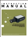
I N S T R U C T I O N
M A N U A L
D&N Network Camera 540TV Lines
Please read this manual thoroughly before use, and keep it handy for future reference.
Design and specifications are subject to change without notice.
WARNINGS AND CAUTIONS:
TO REDUCE THE RISK OF FIRE OR ELECTRIC SHOCK, DO NOT EXPOSE THIS PRODUCT TO RAIN OR
MOISTURE. DO NOT INSERT ANY METALLIC OBJECTS THROUGH THE VENTILATION GRILLS OR
OTHER OPENINGS ON THE EQUIPMENT.
CAUTION:
CAUTION
RISK OF ELECTRIC SHOCK
DO NOT OPEN
CAUTION: TO REDUCE THE RISK OF ELECTRIC SHOCK,
DO NOT REMOVE COVER(OR BACK).
NO USER-SERVICEABLE PARTS INSIDE.
REFER SERVICING TO QUALIFIED SERVICE PERSONNEL.
EXPLANATION OF GRAPHICAL SYMBOLS
The lightning flash with arrowhead symbol, within an equilateral triangle, is
intended to alert the user to the presence of uninsulated "dangerous voltage"
within the product's enclosure that may be of sufficient magnitude to constitute a
risk of electric shock to persons.
The exclamation point within an equilateral triangle is intended to alert the user to
the presence of important operating and maintenance (servicing) instructions in the
literature accompanying the product.
PRECAUTIONS
Safety ----------------------------------- Installation ------------------------------Do not install the unit in an extremely hot or
humid place or in a place subject to excessive
dust, mechanical vibration.
Should any liquid or solid object fall into the
cabinet, unplug the unit and have it checked by
the qualified personnel before operating it any
further.
The unit is not designed to be waterproof.
Unplug the unit from the wall oulet if it is not
Exposure to rain or water may damage the unit.
going to be used for several days or more. To
disconnect the cord, pull it out by the plug. Never Cleaning --------------------------------pull the cord itself.
Clean the unit with a slightly damp soft cloth.
Allow adequate air circulation to prevent internal Use a mild household detergent. Never use
strong solvents such as thinner or benzine as
heat build-up. Do not place the unit on surfaces
they might damage the finish of the unit.
(rugs, blankets, etc.) or near materials(curtains,
draperies) that may block the ventilation holes.
Retain the original carton and packing
materials for safe transport of this unit in the
future.
Height and vertical linearity controls located at
the rear panel are for special adjustments by
qualified personnel only.
ii
FCC COMPLIANCE STATEMENT
FCC INFORMATION : THIS EQUIPMENT HAS BEEN TESTED
AND FOUND TO COMPLY WITH THE LIMITS FOR A CLASS A DIGITAL
DEVICE, PURSUANT TO PART 15 OF THE FCC RULES. THESE
LIMITS ARE DESIGNED TO PROVIDE REASONABLE PROTECTION
AGAINST HARMFUL INTERFERENCE WHEN THE EQUIPMENT IS
OPERATED IN A COMMERCIAL ENVIRONMENT. THIS EQUIPMENT
GENERATES, USES, AND CAN RADIATE RADIO FREQUENCY
ENERGY AND IF NOT INSTALLED AND USED IN ACCORDANCE WITH
THE INSTRUCTION MANUAL, MAY CAUSE HARMFUL INTERFERENCE
TO RADIO COMMUNICATIONS. OPERATION OF THIS EQUIPMENT IN
A RESIDENTIAL AREA IS LIKELY TO CAUSE HARMFUL
INTERFERENCE IN WHICH CASE THE USER WILL BE REQUIRED TO
CORRECT THE INTERFERENCE AT HIS OWN EXPENSE.
CAUTION : CHANGES OR MODIFICATIONS NOT EXPRESSLY
APPROVED BY THE PARTY RESPONSIBLE FOR COMPLIANCE
COULD VOID THE USER'S AUTHORITY TO OPERATE THE EQUIPMENT.
THIS CLASS A DIGITAL APPARATUS COMPLIES WITH CANADIAN
ICES-003.
NORME NMB-003 DU CANADA.
CE COMPLIANCE STATEMENT
WARNING
This is a Class A product. In a domestic environment this product
may cause radio interference in which case the user may be required
to take adequate measures.
iii
IMPORTANT SAFEGUARDS
1. Read these instructions.
2. Keep these instructions.
3. Heed all warnings.
4. Follow all instructions.
5. Do not use this apparatus near water.
6. Clean only with dry cloth.
7. Do not block any ventilation openings. Install in accordance with the
manufacturer's instructions.
8. Do not install near any heat sources such as radiators, heat
registers, stoves, or other apparatus (including amplifiers) that
product heat..
9. Do not defeat the safety purpose of the polarized or grounding-type
plug. A polarized plug has two blades with one wider than the other.
A grounding type plug has two blades and a third grounding prong.
The wide blade or the third prong are provided for your safety. If the
provided plug does not fit into your outlet, consult an electrician for
10. replacement of the obsolete outlet.
Protect the power cord from being walked on or pinched particularly
at plugs, convenience receptacles, and the point where thy exit from
11. the apparatus.
12. Only use attachments/accessories specified by the manufacturer.
Unplug this apparatus during lightning storms or when unused for
13. long periods of time.
Refer all servicing to qualified service personnel. Servicing is
required when the apparatus has been damaged in any way, such
as power-supply cord or plug is damaged, liquid has been spilled or
objects have fallen into the apparatus, the apparatus has been
14. exposed to rain or moisture, does not operate normally, or has been
dropped.
CAUTION - THESE SERVICING INSTRUCTIONS ARE FOR USE
BY QUALIFIED SERVICE PERSONNEL ONLY. TO REDUCE THE
RISK OF ELECTRIC SHOCK DO NOT PERFORM ANY
SERVICING OTHER THAN THAT CONTAINED IN THE
15. OPERATING INSTRUCTIONS UNLESS YOU ARE QUALIFIED TO
DO SO.
Use Certified/Listed Class 2 power supply transformer only.
iv
TABLE OF CONTENTS
1. Production Introduction ................................................................................. 1
1.1
1.2
1.3
1.4
Contents of Package ................................................................................................... 1
Introduction .................................................................................................................. 2
Camera Overview ........................................................................................................ 3
Function Description .................................................................................................... 4
2. Network Camera Installation ......................................................................... 5
2.1 Connection ................................................................................................................... 5
2.1.1 Power Input Terminal ............................................................................................ 5
2.1.2 Video Out Connector ............................................................................................ 5
2.1.3 Network Connector ............................................................................................... 5
2.1.4 Video Auto Iris Installation & Adjustment .............................................................. 6
2.1.5 DC Auto Iris Lens Installation & Adjustment ......................................................... 8
2.1.6 Manual Iris Lens Adjustment ................................................................................ 9
2.2 Back Focus Adjustment ............................................................................................. 10
2.3 Zoom lens Back Focus Adjustment ............................................................................ 11
3. Operating Camera (Analog Mode) .............................................................. 12
3.1 Settings ...................................................................................................................... 12
3.1.1 Main Menu .......................................................................................................... 12
3.1.2 WB ...................................................................................................................... 14
3.1.3 AE ....................................................................................................................... 16
3.1.4 BLC .................................................................................................................... 20
3.1.5 CAM SET ........................................................................................................... 21
3.1.6 SPECIAL ............................................................................................................ 23
3.1.7 D & N .................................................................................................................. 26
3.1.8 DNR .................................................................................................................... 27
3.1.9 MOTION DET ..................................................................................................... 28
3.1.10 END .................................................................................................................. 29
4. Operation by Web Browser ......................................................................... 30
4.1 Accessing the Network Camera by Web Browser ..................................................... 30
4.2 Real-Time Monitoring ................................................................................................ 31
4.3 Network Camera Setting ............................................................................................ 32
4.3.1 Video Setting ...................................................................................................... 32
4.3.2 Alarm Setting ...................................................................................................... 35
4.3.3 System Setting ................................................................................................... 39
4.4 Help ........................................................................................................................... 53
v
5. Operating e-Video Client 4CH .................................................................... 54
5.1 Introduction of Program ............................................................................................. 54
5.2 Preparations before Operating .................................................................................. 54
5.2.1 Minimum System Requirements ........................................................................ 54
5.2.2 Installing e-Video Client 4CH ............................................................................. 55
5.3 Running e-Video Client 4CH For the First Time ........................................................ 56
5.3.1 User Interface ..................................................................................................... 56
5.4 Network Camera Management .................................................................................. 58
5.4.1 Registering Network Camera ............................................................................. 58
5.4.2 Connecting Network Camera ............................................................................. 59
5.5 Real-time Observation ............................................................................................... 60
5.5.1 Operating Network Camera ................................................................................ 61
5.5.2 Screen Selection ................................................................................................ 64
5.5.3 Screen Split ........................................................................................................ 64
5.5.4 Full Screen ......................................................................................................... 65
5.5.5 Sequence Mode ................................................................................................. 65
5.5.6 HDD Space Information ..................................................................................... 66
5.5.7 Operating PTZ Camera ...................................................................................... 67
5.6 Record/Search/Replay Video .................................................................................... 69
5.6.1 Record ................................................................................................................ 69
5.6.2 Search ................................................................................................................ 71
5.6.3 Replay ................................................................................................................ 72
5.7 Setup ......................................................................................................................... 74
5.7.1 Setting up Network Cameras ............................................................................. 74
5.7.2 Setting up e-Video Client 4CH ........................................................................ 86
5.8 Log ........................................................................................................................... 87
5.8.1 System Log ...................................................................................................... 87
5.8.2 Event Log ......................................................................................................... 88
5.9 Viewing Information ................................................................................................. 88
6. Appendix ................................................................................................... 89
6.1
6.2
6.3
6.4
Troubleshooting .........................................................................................................
Preventive Maintenance ............................................................................................
Product Specifications .............................................................................................
Network Camera IP Assignment ..............................................................................
vi
89
89
90
91
1. Production Introduction
1.1 CONTENTS OF PACKAGE
Installation of the camera must be performed by qualified service personnel
in accordance with all local and national electrical and mechanical codes.
Carefully remove the color camera and its accessories from the carton
and verify that they were not damaged in shipment.
The contents of the package includes:
1. Color CCD camera
2. Mini-DIN connector (for video-or dc-type auto-iris lens)
-1-
1.2 INTRODUCTION
The camera provides high-quality images using SONY CCD technology
especially designed for closed-circuit television (CCTV) and security
surveillance applications. The NETWORK CAMERA supports the operation
through the network.
Features:
High resolution and high performance 1/3" SONY Super HAD CCD technology.
Full frame rate up to D1 (25fps@720x576, 30fps@720x480) resolution compatible
with MPEG4 standard.
Superior image quality (540 TV Lines).
0.3 Lux(Color) @ F1.2 Sensitivity.
C/CS, backfocus cam for easy adjustment.
Auto electronic shutter [1/60(1/50) ~ 1/120,000] and manual electronic shutter modes.
Full control via the OSD menu key on the rear of the camera.
Auto and manual white balance modes .
BLC (Back Light Compensation)
Day&Night (Auto / Color / B/W)
AGC (Auto Gain Control)
Incredible noise reduction for picture quality & file size.
Sens-up (x2 ~ x128)
Privacy Zone 4point.
MIRROR
VIDEO OUT(BNC)
Motion Detection 4point.
Internal / AC line lock.
Built-in network interface (10Base-T/100Base-TX) for remote monitoring by PC.
Interface protocol : TCP/IP, HTTP, UDP, DHCP, RTP, RTSP, SMTP, DDNS.
Compatible with video- or DC-type lenses with OSD select.
Quick connect for video or DC lens with 4-pin connector.
Supports pre & post alarm record in client PC
Notify events via e-mail
Quick & Easy set up with user friendly GUI
Operates in 12VDC.
Use Certified / Listed Class 2 power supply only.
IMPORTANT : The user of this camera is responsible for
checking and complying with local, state, and federal laws
and statutes concerning the recording and monitoring of
audio signals.
-2-
1.3 CAMERA OVERVIEW
C Mount Ring
134.5mm
(C MOUNT LENS)
(CS MOUNT LENS)
[ SIDE VIEW ]
32.0mm
56.0mm
1-32UNEF
18.0mm
69.0mm
1/4-20UNC
[ FRONT VIEW ]
[ TOP VIEW ]
-3-
1.4 FUNCTION DESCRIPTION
[ SIDE VIEW ]
2
1
1
Focus Adjusting Fixing Screw
2
Auto Iris Lens Connector
[ REAR VIEW ]
3
4
5
6
1
Down Button
2
Left Button
3
Enter Button
4
Up Button
5
Right Button
6
Power Indicator
7
Video Out Connector
POWER
VIDEO OUT
2
7
ENTER
1
NETWORK
8
9
DC 12V
-4-
8
Network Connector
9
DC 12V Compatible Input Terminal
2. Network Camera Installation
2.1 CONNECTIONS
2.1.1 POWER INPUT TERMINAL
Power input terminal
Receives DC12V from the power supply.
Use Certified / Listed Class 2 power supply only.
CLASS 2
+ DC 12V -
2.1.2 VIDEO OUT CONNECTOR
BNC : This BNC connector provides a 1.0Vp-p/75
ohms composite video signal.
VIDEO OUTPUT
2.1.3 NETWORK CONNECTOR
NETWORK
Network Connector : The Network Camera
supports the operation through the network.
Therefore, it is necessary to connect a standard
RJ-45 cable to it. Generally a cross cable is used
for directly connection to PC, while a direct cable
is used for connection to a hub.
-5-
2.1.4 VIDEO AUTO IRIS INSTALLATION & ADJUSTMENT
The camera supports video-type auto iris lenses which adjust to changing
light levels. Perform the following steps to install and adjust a video-type
auto iris lens.
1. If necessary, solder the lens control wires to the connector supplied with
the camera.
Connector
Cover
Rib
Pin 3
Automatic
Iris Lens
Pin 1
Heat
Pin 4
Shrinkable
Tubes
Iris Control
Pin 2
Cable
Connector
PIN
NAME
WIRE COLOR
1
Voltage +
2
Open
Red
_
3
Video
White
4
Ground
Black
2. Attach the video-type auto iris lens to the lens mount on the front of the
camera.
3. IMPORTANT: The minimum Plug the connector from the lens into the
auto iris jack on the back of the camera. The connector is polarized and
can only be inserted into the jack one way.
4. Apply power to the camera.
5. The OSD AE menu in the lens select should be in the “VIDEO ”.
6. Adjust the focus ring on the lens for an optimum picture. If a picture is
not visible, set the lens for proper exposure by adjusting the ALC
(Automatic Level Control) and the level on the lens. The ALC setting
can range between AVG (average) or PK (peak). A midrange setting is
appropriate for most applications.
-6-
For ALC adjustments:
AVG To slow the reaction of the lens to changing light, set the range to
the AVG setting to average the video level from the camera. Use when
there are bright spots in the picture such as lights or glare from the sun.
PK To increase the speed of the lens reaction to the changing light, set
the lens adjustment to PK so the lens will adjust to the brightest or peak
object in the video. Use this setting if you want to see the brightest
object and not the background objects.
For Level adjustments:
Adjust the level control for the best picture during the day. A night
adjustment may not provide the proper setting for controlling the light
during the day.
7. Set the back focus of the camera before the final adjustment of the
video level.
8. If the auto iris has a gain adjustment and the picture oscillates between
open and closed under bright lights, slowly turn the gain adjustment
counter clockwise until the oscillating stops. Increase the light getting to
the camera by adjusting the level control and re-adjusting the gain
control.
-7-
2.1.5 DC AUTO IRIS LENS INSTALLATION & ADJUSTMENT
The camera supports DC-type auto iris lenses. Perform the following
steps to install and adjust a DC-type auto iris lens.
1. Solder the lens control wires to the connector supplied with the camera.
Connector
Cover
Rib
Pin 3
Automatic
Iris Lens
Pin 1
Heat
Pin 4
Shrinkable
Tubes
Iris Control
Pin 2
Cable
Connector
NAME
WIRE
COLOR
1
Damp Coil -
Blue
2
Damp Coil +
Red
3
Drive Coil +
White
4
Drive Coil -
Green
PIN
2. Attach the DC-type auto iris lens to the
lens mount on the front of the Camera.
3. Plug the connector into the auto iris
jack on the back of the camera. The
connector is polarized and can only be
Inserted into the Jack one way.
4. Apply power to the camera.
5. The OSD AE menu in the lens select should be in the "DC ".
6. Adjust the auto iris lens for an optimum picture using the LEVEL control
on the "DC " of the OSD AE MENU.
-8-
2.1.6 MANUAL IRIS LENS ADJUSTMENT
When using a manual iris lens, turn the iris ring on the lens to the OPEN
position and adjust the manual iris for the appropriate range. Adjust
during the brightest conditions, opening the lens to the minimum f-stop
yielding a good picture under the brightest scene conditions. Do not
saturate the picture.
The manual iris is used in indoor applications where lighting from windows
can considerably affect the light level of the room.
-9-
2.2 BACK FOCUS ADJUSTMENT
For best results, perform back focus adjustments at night or while using a #6
or #8 welder's glass in front of the lens. The focus of the camera will
change slightly if the camera iris was adjusted on a light scene, then
changes to a dark scene. However, the camera will remain in focus if the
iris was focused on a dark scene and the scene lightens.
1. The lens should be mounted on the camera before applying power.
2. If a picture is visible, focus on the picture. If the picture is not visible,
open the iris on the lens. Open the lens as wide as possible by placing
the welder's glass in front of the lens and forcing the lens to automatically
open.
3. When the iris is open to the widest point, re-adjust the focus for clear
picture. If a clear picture is not possible, set the focus ring to midrange.
4. Loosen the back focus lock screw.
5. Adjust the back focus ring for a clear picture.
6. Tighten the back focus lock screw.
7. Fine tune the focus with the focus ring on the lens.
8. Remove the welder's glass from in front of the lens.
9. Adjust the iris of the lens for the best picture quality.
- 10 -
2.3 ZOOM LENS BACK FOCUS ADJUSTMENT
The objective of back focusing a zoom lens is similar to that of a fixed focal
length camera except the back focus is also adjusted to maintain the focus
when "zooming" the lens in and out on a scene.
1. Choose an object at the farthest range set for viewing with a zoom lens.
2. Make sure the iris of the lens is wide open. Do this by adjusting the
camera at night or use a welders glass in front of the lens.
3. Adjust the focus to the stop on the far range.
4. Adjust the zoom on the lens to obtain the widest picture.
5. Loosen the back focus lock screw.
6. Adjust the back focus ring for the clearest picture.
7. Tighten the back focus lock screw.
8. Adjust the zoom on the lens to the far telephoto position.
9. Adjust the back focus ring for the clearest picture.
10. Adjust the zoom on the lens back to the widest picture.
11. Loosen the back focus screw.
12. Re-adjust the back focus for the clearest picture.
13. Tighten the back focus lock screw.
14. Repeat the previous steps as necessary to maintain a clear picture
throughout the entire zoom range.
- 11 -
3. OPERATING CAMERA (Analog Mode)
3.1 SETTINGS
Settings can be made using the 5 buttons located on the back of the camera.
<MAIN MENU>
WB
AE
BLC
CAM SET
SPECIAL
D&N
DNR
MOTION DET
END
OFF
3.1.1 Main Menu
1)
The MAIN MENU is displayed on the monitor when press the
ENTER button.
2)
Please select any function you wish to activate by using the UP and
DOWN buttons.
The arrow can be moved up or down by using the UP and DOWN
buttons. Please position the arrow to point to the function you
wish to operate.
<MAIN MENU>
Select any function
you wish to operate
by using the
UP and DOWN buttons.
WB
AE
BLC
CAM SET
SPECIAL
D&N
DNR
MOTION DET
END
- 12 -
If appears at the mode
you wish to operate,
it means that there is a
sub menu which can be
selected by pressing the
ENTER button.
OFF
Modes can be changed
using the LEFT or RIGHT
buttons.
3)
Press the LEFT or RIGHT button if you wish to change mode.
When the LEFT or RIGHT button is pressed, available values and
modes are displayed in order. Please keep pressing the button
until you get to the mode you wish to operate.
4)
To finishing the setting without save, select 'END' and then press
the ENTER button. But if you want to keep the setting, enter the
CAM SET menu, select 'SAVE' and then press the ENTER button.
NOTE : If ' - - -' appears at the mode item, it means that is no mode
available to be selected.
- 13 -
3.1.2 WB
Press the MENU button to access the "WB" mode.
WHITE BAL.
MODE
ATW / AWC
/ MANUAL
R GAIN
1 ~ 70
B GAIN
1 ~ 70
END
1)
MODE
- ATW (Auto Tracking White Balance)
This mode can be used within the color temperature range 1,800OK
~ 10,500OK
- AWC (Auto White Balance Control)
Please press the MENU button while the camera is directed at a
piece of white paper to obtain the optimum state under current
illumination. If the environment including the light source is
changed, you have to adjust the white balance again.
- MANUAL
The manual adjustment mode enables finer adjustment. You can
adjust the RED and BLUE color values while monitoring the color
changes on the object at the 'R GAIN' or 'B GAIN' menu. The 'R
GAIN' and 'B GAIN' is available only at the MANUAL mode.
- 14 -
NOTE : Under the following conditions the WHITE BALANCE function
may not operate properly. In such cases, please select the AWC
mode.
- When the object's surroundings have a very high color
temperature. (eg. A clear sky and sunset)
- When the object's surroundings are dark
- If the camera directly faces a fluorescent light or is installed in a
place where there are considerable changes in illumination, the
WHITE BALANCE function may become unstable.
2)
R GAIN
Adjust the R GAIN by using the LEFT or RIGHT button.
(This is effective only in case of selecting the MANUAL MODE)
0 ~ 100
3)
B GAIN
Adjust the B GAIN by using the LEFT or RIGHT button.
(This is effective only in case of selecting the MANUAL MODE)
0 ~ 100
4)
END
RETURN to MAIN MENU.
- 15 -
3.1.3 AE
Press the MENU button to access the "AE" mode.
AUTO EXPOSURE
MODE
-AUTO
BRIGHTNESS
END
-SHUTTER
SHUTTER
END
1 ~ 70
X128~1/120,000
-FLK
AGC
-HIGH
BRIGHTNESS
END
1 ~ 70
-MORMAL
BRIGHTNESS
END
1 ~ 70
-OFF
LENS
-MANUAL
-DC
BRIGHTNESS
END
-VIDEO
SENS-UP
-OFF
-AUTO
AUTO
END
1 ~ 70
X2~X128
END
- 16 -
1)
MODE
- AUTO
Auto control of the shutter speed can be achieved. When AUTO
mode is on, the speed is controlled automatically according to the
brightness of the screen.
BRIGHTNESS
LEVEL
Adjust the "BRIGHTNESS" to the desired
by using LEFT or RIGHT button.
END
RETURN to AE MENU
- SHUTTER
The shutter speed can be controlled manually.
X128 ~ 1/120,000
- FLK
Please select 'FLK' mode when flickering occurs on the screen, due
to an imbalance between illumination and frequency.
NTSC Model : 1/100, PAL Model : 1/120
NOTE :
- When selecting DC/VIDEO lens, you can choose 'FLK' or '1/60 or
1/50'. The 'FLK' functions FLICKLESS OFF and the '1/60 or 1/50'
functions E/I OFF.
- While using the internal system, if the shutter setting is on 'AUTO'
and the camera is directly facing a bright fluorescent light, the image
on the screen can be adversely affected. Therefore please choose
the installation location with care.
- When 'SHUTTER' mode is on, the SENS UP function does not
operate.
2)
AGC (Auto Gain Control)
Adjust the AGC GAIN to the desired mode by using LEFT or RIGHT
button. As the level of gain increases, the screen gets brighter and
the level of noise also increases.
- HIGH / MORMAL / OFF
BRIGHTNESS
Adjust the "BRIGHTNESS" to the desired
LEVEL by using LEFT or RIGHT button.
1 ~ 70
END
RETURN to AE MENU
- 17 -
3)
LENS
Automatic control of the brightness level through the intensity of
radiation.
- MANUAL
Available by using manual lens.
- DC
LEVEL
Adjust the brightness level by pressing the LEFT or
RIGHT button at the DC's submenu. Level setting
is available only by using the DC IRIS lens.
Then put the A/I LENS selection switch on the side
of the camera in the "DC" position.
END
RETURN to the AE MENU
- VIDEO
NOTE :
- When using an auto iris lens, the setting of the auto iris lens selection
switch, located on the back of the camera, must be on DC or VIDEO
depending on the type of the lens which is being used.
- The brightness of the screen can be adjusted in DC mode. The
brightness can be adjusted within the range of 0~70. The optimum
level of brightness for the user can be achieved by adjustment.
When using Auto Iris Lens with Video type
1) Adjust ALC volume on the lens properly. Normally ALC volume
should be turned all the way to Av(Average).
2) According to the type of the lens used, the lens may not perform
properly. In such a case, adjust the volume level on the lens.
3) For adjusting the Volume Level, enter the submenu at the
‘VIDEO LENS’ mode. And then adjust it to the desired state.
NOTES
When the auto iris is mounted, you have to set the DC/Video
selection switch on the side of the camera properly according to
status of this selection switch.
- 18 -
4)
SENS-UP (Low illuminance)
SENS UP helps maintain a bright, clear screen image by
automatically detecting changes in the level of light in low light
level conditions.
- OFF
The function does not operate.
- AUTO
Low light level auto mode.
X2 ~ X128
NOTE :
- When SHUTTER is in the manual mode, SENS UP does not operate.
- When AGC is turned off. SENS UP does not operate.
NOTE :
- The maximum storage magnification in low light level movement
situations can be adjusted by pressing the ENTER button in 'AUTO'
mode. (x2 ~ x128)
- As the magnification increase, the screen gets brighter; however the
after image also increases.
- If storage magnification is increased while SENS UP is operating, it
may cause noise, and spots may appear; however this is normal.
5)
END
RETURN to the MAIN MENU.
- 19 -
3.1.4 BLC
Press the MENU button to access the "BLC" mode.
BLC
LEVEL
LOW / MIDDLE / HIGH / OFF
END
Prevents such a back light effect to secure a clear image under all
illumination environments.
1)
LEVEL
LOW / MIDDLE / HIGH / OFF
2)
END
RETURN to MAIN MENU.
- 20 -
3.1.5 CAM SET
Press the MENU button to access the "CAM SET" mode.
CAM SET
TITLE
DISPLAY ON / OFF
DEFAULT
SAVE
END
1)
TITLE
Select the camera TITLE that may be composed of letters,
numbers, special texts, or a combination of these up to 15
digits.
-
Move to left
-
Move to right
- CLR
Erase all character
- POS
Change the position of the title
(If you want to change the position of the title, press
ENTER button at the POS. Find the position you
wish to display the title by using the 4 directional
buttons, and then press the ENTER button.)
- END
End
NOTE :
- If the wrong name has been input....
If you press the ENTER button after moving the cursor the CLR, all
the letters will be erased. If you want to correct a letter, please
move the cursor to the arrow at the bottom left of the screen and
press 'ENTER'.
Please position the cursor above the letter you wish to correct, and
then move the cursor onto the letter you wish to choose and press
the ENTER button.
- 21 -
2)
DISPLAY
ON : Display TITLE in the monitor.
OFF : Disappear TITLE in the monitor.
3)
DEFAULTS
The factory setting of the Camera is selected.
4)
SAVE
The changed Baud Rate is saved.
5)
END
- 22 -
3.1.6 SPECIAL
Press the MENU button to access the "SPECIAL" mode.
SPECIAL
SHARPNESS
-OFF
-ON
LEVEL
END
MIRROR
0 ~ 31
OFF / ON
SYC
-INT
PRIVACY
-OFF
-ON
AREA SEL
AREA1 / AREA2 / AREA3 / AREA4
AREA STATE OFF / ON
AREA TONE
1 ~ 100
TOP
1 ~ 62
DOWN
1 ~ 62
LEFT
1 ~ 96
RIGHT
1 ~ 96
END
END
1)
SHARPNESS
The outline of the video image becomes cleaner and more distinctive
as the level of SHARPNESS increases. If the level goes up
excessively, however, it may affect the video image and generate
noise.
- LEVEL
Adjust the SHARPNESS of the screen by using the LEFT or RIGHT
button.
0 ~ 31
- END
RETURN to SPECIAL MENU
- 23 -
2)
MIRROR
ON: Sets a horizontal image inversion.
OFF: Cancels the inversion.
3)
SYNC
Two SYNCHRONIZATION modes are available INTERNAL and
EXTERNAL LINE-LOCK. In LINE-LOCK mode, it synchronizes the
video signal between cameras without a synchronous generator. The
line-lock synchronization is only used in the areas of 60Hz(NTSC
Models) / 50Hz(PAL Models)
- INT
This mode is necessary for using the internal synchronization.
NOTE :
- When the power frequency is 50Hz, you can not use line-lock
mode (NTSC Models).
- When the power frequency is 60Hz, you can not use line-lock
mode (PAL models).
- 'Sync' mode is fixed to 'INT' in DC 12V input power.
- 24 -
4)
PRIVACY
Conceals the areas you do not wish to appear on the screen.
OFF : Cancels the PRIVACY mode.
ON : Operates the PRIVACY mode. To adjust PRIVACY MASK, press
'ENTER' button.
- AREA SEL
Select the AREA you want to adjust.
- AREA STATE
Select 'ON' to display the selected AREA, and select 'OFF' to
conceal the selected AREA.
- AREA TONE
Adjust the tone of the selected AREA.
1 ~ 100
- TOP
Adjust the TOP of the selected AREA by using the LEFT or RIGHT
button.
- DOWN
Adjust the DOWN of the selected AREA by using the LEFT or
RIGHT button.
- LEFT
Adjust the LEFT of the selected AREA by using the LEFT or RIGHT
button.
- RIGHT
Adjust the RIGHT of the selected AREA by using the LEFT or
RIGHT button.
- END
RETURN to SPECIAL MENU.
5)
END
RETURN to MAIN MENU
- 25 -
3.1.7 D&N
Press the MENU button to access the "D&N" mode.
D&N
MODE
AUTO / BW / COLOR
END
1)
D&N
- AUTO
The COLOR / BW menu turns the IR(infrared) Filter to on or off. In
low illumination environments, the BW mode will turn off the IR
Filter and the sensitivity will be as high as that of BW cameras.
Otherwise, the BW mode will turn on the IR Filter and the sensitivity
will return to normal to recover the normal screen.
- BW
In this mode, the camera outputs the video image only in black and
white.
- COLOR
In this mode, the camera outputs the video image only in color.
2)
END
RETURN to MAIN MENU.
NOTE :
- When the AGC is turned off. AUTO does not operate.
- When an infrared light is used, there may be a problem with
focusing.
- 26 -
3.1.8 DNR
Press the MENU button to access the "DNR" mode.
DNR
LEVEL
LOW / MIDDLE / HIGH / OFF
END
The background noise in the low light level decreases automatically as the
level of gain changes.
1)
LEVEL
- OFF
There is no reduction in noise level.
- LOW
There is a small reduction in noise level with almost no ghost
image.
- MIDDLE
The most effective mode. There is a sufficient reduction in noise
levels without causing much ghost imaging.
- HIGH
The level of noise is reduced greatly, however there is an increase
in ghost imaging.
2)
END
RETURN to MAIN MENU.
NOTE :
- When AGC is turned off. DNR does not operate.
- 27 -
3.1.9 MOTION DET
Press the MENU button to access the "MOTION DET" mode.
MOTION DETECTION
AREA SEL
AREA1 / AREA2 / AREA3 / AREA4
AREA STATE OFF / ON
TOP
1 ~ 62
DOWN
1 ~ 62
LEFT
1 ~ 96
RIGHT
1 ~ 96
END
This product has a feature that allows you to observe movements of
objects in 4 different areas on the screen, and the words 'MOTION
DETECTED' is appeared on the screen when movement is detected;
hence a single individual can conduct supervision efficiently. The camera
detects an object's movement by sensing disparity of outline, and level of
brightness and color.
OFF : MOTION DETECTION mode is cancelled.
ON : Any motion in the selected areas is observed.
1)
AREA SEL
Select the AREA you want to adjust.
2)
AREA STATE
Select 'ON' to display the selected AREA, and select 'OFF' to conceal
the selected AREA.
3)
TOP
Adjust the TOP of the selected AREA by using the LEFT or RIGHT
button.
4)
DOWN
Adjust the DOWN of the selected AREA by using the LEFT or RIGHT
button.
- 28 -
5)
LEFT
Adjust the LEFT of the selected AREA by using the LEFT or RIGHT
button.
6)
RIGHT
Adjust the RIGHT of the selected AREA by using the LEFT or RIGHT
button.
7)
END
RETURN to MAIN MENU.
3.1.10 END
Terminate the MAIN MENU without save the changed preset parameter.
- 29 -
4. Operation by Web Browser
4.1 Connecting the Network Camera by Web Browser
Execute the Web Browser on the PC.
Enter the Network Camera address on the address window of
the Web Browser and execute it.
Ex) http://192.168.0.2/
(If the Network Camera has no IP address or its IP address
is wrong, users will fail to connect the Network Camera. In
this case, users will have to connect the Network Camera by
the Web Browser after entering the IP address with the IP
Utility.)
Refer to '6.3 Network Camera IP Assignment' section for detailed
information.
If a security window for the ActiveX Controller installation
appears, press the Confirm and install it.
If it is not connected in the Internet, from the CD-ROM install
the ActiveX Controller by manual operation.
- 30 -
4.2 Real-Time Monitoring
The monitoring screen comes in four screen modes like D1, 640 X
480, 320 X 240, and 160 X 120. Users are allowed to select the most
suitable one out of those modes. Please, adjust the mode in
accordance with your PC specifications and monitoring purposes.
In case of real-time monitoring with the Web Browser, one Network
Camera will be connected to just one Web Browser. However, this case
is not suitable for monitoring various screens at the same time. If users
are to monitor various images at the same time, please refer to the
“Chapter 5 Operation by e-Video Client 4CH.”
HTTP tunnel mode
When the screen is not indicated, check.
(Notice: "unicast mode" only it is applied.)
- 31 -
4.3 Network Camera Setting
Network Camera setting is divided into video, audio, alarm, PTZ
and system settings. And the detailed screen will be provided for
each setting.
4.3.1 Video Setting
The video setting is classified into Basic. The Basic menu
includes a setting menu for real-time monitoring. Its setting only is
enough to complete a setting for viewing the monitoring screen.
The detailed setting menu is able to perform screen sizing,
filtering, compressibility, and brightness control.
Basic Setting
Image Appearance
Resolution
It enables users to determine a basic screen size when having
an access through the Web Browser or PC program.
The screen size control comes in four modes like D1, 640 X 480,
320 X 240, and 160 X 128. Users can reset the selected screen
size anytime while monitoring the screen on a real-time basis.
Image filter
The image filter control enables users to reinforce the image
quality in a strong or weak way. The default is "disabled.”
- 32 -
Compression
When it is necessary to adjust a smooth transmission status
according to network situations, users can increase the
compressibility to carry out the network transmission stably.
On the other hand, when it is necessary to maintain a detailed
monitoring screen by enhancing the image quality, users can
do so by decreasing the compressibility. In ease case, please
adjust this function according to the network status and
monitoring purposes. The default is 2000(Kbps).
BCS Adjust
Brightness
The screen brightness can be adjusted from 0 to 255 stages,
and the default is 128. The brightness may differ depending on
the equipment and PC monitor status.
Contrast
The screen contrast can be adjusted from 0 to 127 stages, and
the default is 73. The contrast may differ depending on the
equipment and PC monitor status.
Saturation
The screen saturation can be adjusted from 0 to 127 stages, and
the default is 64. The saturation may differ depending on the
equipment and PC monitor status.
- 33 -
MPEG4 Video Stream
Frame rate
Upon the real-time play, users should select a frame refresh
rate per second. If the rate is high, the image will become
smooth. On the other hand, if the rate is low, the image will not
be natural but it can reduce a network load.
Bit-rate control
-Variable bit rate (VBR): It refers to the type of using a variable
bit rate (VBR). Increase a bit rate for the image with much
motion, and decrease a bit rate for the image with little motion.
The basic setting value is a VBR type.
-Constant bit rate (CBR): Using a constant bit rate (CBR) may
guarantee a stable play. However, if a large amount of data is
not required, it may cause the waste of a transmission rate. If a
large amount of data is required, it may cause the image quality
to be decreased.
Profile
SP (Simple Profile) is available up to the CIF resolution and
384kbit/s.
ASP (Advanced Simple Profile) is available up to the 4CIF
resolution and 8000kbit/s.
GOV size
Enter the GOV (group of VOP) size. If users want to have a high
quality of fast image one by one, please decrease the value.
For the purpose of general monitoring, please do not change a
basic value. Such act may cause a problem to the system
performance. For the details of GOV setting, please contact
the service center.
- 34 -
4.3.2 Alarm Setting
Alarm In Setting
This function enables users to conduct the alarm input/output setting
and event setting.
Motion Detection Setting
Motion information is processed by splitting the screen into 64 areas.
Each area can be selected by clicking with the mouse, and green
point shown in the selected area. The area which uses the motion
information as an event is shown green point, while the area which
does not use the information is indicated empty.
Enable
Check this item when using the motion information.
- Sensitivity
This sets up the sensitivity for the motion detection.
- 35 -
- Motion dwelling time
This sets up the event dwelling time when a motion occurs. This can
be set in the range of 0 ~ 6 seconds. When an event occurs, the
motion icon at the upper right blinks in red for the preset time period.
When another motion occurs during the motion event, the dwelling
time is extended on the basis of the occurring time of the second
event.
- Enable down FPS
This feature decreases frame rate to about 1 FPS when no motion
event occurs, while operates with the frame rate set in this item when
a motion event occurs.
Alarm Out Setting
Upon the alarm occurrence, this function enables users to receive a
text message or mailing service to the mail address designated by
users.
- 36 -
SMPT(eMail) Setting
Sender : Enter an eMail address to send a mail.
Receiver list: Enter up to 10 eMail addresses to receive a mail.
Email test: Enter an eMail address to test for sending a mail.
Tset button : Test for sending a mail with a value entered.
FTP & JPEG Setting
-FTP Settings
Enable
Checks to activate the FTP function.
Sender name or IP : Enters the FTP IP address or host name to be
received.
Port : Enters the port number of FTP to be received.
Remote Directory : Enters the location for saving the file of FTP to be
received.
Username : Enters the user's account when connecting to FTP.
Password : Enters the user password for connecting to FTP.
-JPEG Settings
Sets up the creation condition, screen size, color and name of JPEG
file to be sent to FTP.
Pre event : Creates the JPEG file of chapter 1~5 for 1~2 seconds
before the event is generated.
Post event : Creates the JPEG file of chapter 1~15 for 1~2 seconds
after the event is generated.
Image size : Selects the size of JPEG file to be created among
160X120 and 320X240.
Color : Selects the color or B&W of JPEG file to be created.
Base name : Write in the basic name of file to be created.
Except for the basic name, It is possible to add
supplementary names for discriminating multiple files.
Additional suffix : Selects one among date, time and the number of
sequence created.
-None : Do not add supplementary names.
-Date Time : Adds the date and time when the file was created behind
the basic name.
-Sequence : Adds the number in sequence of file creation behind the
basic name.
- 37 -
Event Setup
IN-OUT Mapping
By connecting the Alarm OUT operations to the events occurred from
the Alarm IN, users can send an eMail or FTP Server.
Alarm IN - Alarm IN comes in Motion.
Alarm OUT
- eMail : Send an eMail to events occurred from the Alarm IN.
- FTP : Sends the captured picture to FTP by the event which occurs
from Alarm input.
- 38 -
4.3.3 System Setting
Users Setting
This Network Camera 's Authority Policy
1. Anonymous User Access Permit Mode
This mode enables any anonymous users to have an access to
the Network Camera to monitor and set it.
2. Anonymous User Access Denial Mode
Upon selecting this mode, the Network Camera operates in two
authority groups. And it also requires a log-in process when users
are to have an access to the Network Camera to change a
screen monitoring or setting.
1) Administrator Authority Group (admin)
It enables administrators to change the screen monitoring and
setting of the Network Camera. In addition, this authority allows
only one user to have an access to the Network Camera at
once.
2) General User Authority Group (user)
It enables users to simply use a screen monitoring function. It
disables users to change the Network Camera setting but
allows them to have a multiple access at the same time.
- 39 -
User setting
Enable anonymous viewer login: Check it when users do not want to
use the Network Camera without the user account.
When using the user account, users have to try log-in at every access.
Admin Setting
User name: Enter a user name for the administrator use.
Password: Enter the password for the administrator use.
User List Setting
Show a registered user account.
- Add User
Enter a user name and password to be added, and register them by
pressing the Add button.
- 40 -
- Modify User Information
After selecting a user to be corrected and changing its name and
password, press the 'modify' button to reflect the corrected information.
- Delete User Account
After selecting a user to be deleted, delete it by pressing the
Remove button.
- 41 -
Date / Time Setting
Date & Time
- Current Time: Indicate a current time.
Date: Indicate a current day, month, and year.
Time: Indicate a current day, month, and year.
- Time Zone
Time Zone: Select a time zone to be used.
Automatically adjust for daylight saving time changes:
Check it if users are to apply the Summer Time.
- New Time
Synchronize with computer time: Synchronize the time with that of a
current user computer.
Synchronize with NTP server: Synchronize the time with that of the
NTP server.
Receive the time information from the NTP (RFC2030) server.
Synchronize with date server: Enter the Time Server address to be
synchronized. Receive the time
information from the Time Server that
complies with the Time protocol (RFC868).
Set manually: Users enter a current time directly.
Date: Enter a current day, month, and year.
Time: Enter a current day, month, and year.
- 42 -
Network Setting
Setting in regard to network can be executed. Settings for IP,
DNS, Host Name, Port, and Network traffic can be established,
along with setting for DDNS and RTP.
Basic Setting
Basic settings for IP, DNS, Host Name, and Port are possible,
and possibly works as a adjustment role in reducing the overload
of network bandwidth in use, by applying Network traffic
capability.
- 43 -
IP address Configuration
Obtain IP address via DHCP: Obtain an IP through the DHCP
automatically.
Use Following IP address: Users enter a Network Camera IP
directly.
DNS Configuration
Obtain DNS server address via DHCP: Obtain the DNS
information through the DHCP.
Use Following DNS server address: Users enter the DNS
information directly.
Domain name: Enter a domain name to be used.
Primary DNS server: Enter the first domain name server.
Secondary DNS server: Enter the second domain name server
address.
Host Name Configuration
Obtain Host Name via DHCP: Obtain a Network Camera name
from the DHCP automatically.
Use Following Host Name: Users enter a Network Camera name
directly.
Services
HTTP port: Enter a port to receive a service through the HTTP.
Default Port Number is '80'.
RTSP port: Enter a port to receive a service through the RTSP.
Default Port Number is '7070'.
Network traffic - Maximum bandwidth
Set a limitation on user network resources by designating the
maximum bandwidth.
Unlimited: Selected if not influenced by a network-related
program or equipment without a limitation on the network
bandwidth.
Limited to: In case of sharing other network programs or
equipment, it is possible to set a limitation on the maximum
bandwidth in the unit of Mbit/s or kbit/s.
- 44 -
DDNS Setting
Internet Dynamic DNS
When using the high-speed Internet with the telephone or cable network,
users can operate the Network Camera even on the floating IP
environment in which IPs are changed at every access.
Users should receive an account and password by visiting a DDNS
service like http://www.dyndns.com/.
Enable
Check to get DDNS service to be available.
Registered host: Enter an address of the DDNS server.
Username: Enter an ID to access to the DDNS server.
Password: Enter a password to be used for accessing the DDNS
server.
Confirm: Enter a password again to confirm it.
Maximum time interval: Set a time interval to synchronize with the
DDNS server.
Register local network IP address: Register a Network Camera IP
address to the DDNS server.
- 45 -
RTP Setting
Have a setting for sending and receiving an audio or video on a
real-time basis.
Stream RTP after Network Camera start-up
Enter a destination IP and Port to send movie data automatically through
the RTP while the Network Camera has booting.
Send to DHCP server IP: Send movie data to the DHCP server.
Send to (Client) IP: Send movie data to other certain destination
addresses.
Use RTP destination Port: Available from 1024 to 65532, and the
default is 5000.
Do not send: Do not send a stream to the FTP until it is requested
from a client.
- 46 -
Enable multi stream
Check it to send data for the purpose of saving them into an external
extension storage right after the Network Camera operates.
- Send to secondary client ip : Enter an IP address of the external
extension storage.
- Use RTP destination port : Enter a Port number of the external
extension storage. The Port number to be
used is [1024 ~ 65532].
- Frame rate : Indicate a frame rate that is sent to the external extension
storage when the multi stream works.
Once the multi stream function is checked, the MPEG profile setting will
be changed to the Advanced Simple Profile.
RTSP/RTP settings
Perform a multicast setting to send a video and audio to multiple users.
(Up to 10 users).
RTP destination IP
Disable Multicast : Do no use the multicast.
Enable Multicast : Use the multicast.
- Multicast destination IP : Enter an IP between 224.0.0.0 and
239.255.255.255. Although it is empty,
an IP will be entered automatically.
- RTP port : Enter a value between 1024 and 65532.
- RTP TTL : Enter a value between 1 and 255. If a network status is
smooth, enter a lower value. On the other hand, if a network
status is poor, enter a higher value. When there are many
Network Camera or users, a higher value may cause a
heavy load to the network. For a detailed setting, please
consult with a network manager.
- 47 -
Language
Language
It will be able to select a user language. The type of language it will be
able to select is the English, the French, the German and the Spanish.
- 48 -
Maintenance
Maintain Server
< Restart > Restart the Network Camera.
< Userset > Initialize a user setting value of audio/video, alarm, etc.
< Restore > Restore all the values except a network-related setting to a
basic value.
< Default > Restore all the setting values to a basic value.
Upgrade Server
Carry out the upgrade by importing an upgrade file and pressing the
'Upgrade' button. During the upgrade, do not turn off the power of the
Network Camera. And try an access again after waiting five minutes or
longer.
Backup
Save a setting value that users enter to the Network Camera, to a user
PC.
Restore
Import and apply a setting value saved to a user PC.
- 49 -
Program Support Information
Troubleshooting
When problems occur during operation, please consult with an
installer.
Server Report
If its support is requested, please attach a server report.
- 50 -
Log & Reporte
Users can check the system log and server report.
Logs
Users can check the log for Network Camera
operation by clicking the < Logs >.
Reports
Users can check a server report by clicking the < Server Report >.
Users can check a parameter by clicking the < Parameter List >.
- 51 -
Program Information
The following website will provide the support information for the
Network Camera system information and operation.
- 52 -
4.4 Help
The Help information window will be provided as a popup window so
that users can open and read it without a need for log-in. It will offer a
description on setting and Help page by which users can manipulate
the Network Camera without a reference to the manual.
- 53 -
5. Operating e-Video Client 4CH
5.1 Introduction of Program
The PC program is used for operating multiple Network Cameras. This
program can be installed from the supplied CD-ROM disk.
You can observe, record and playback up to four Network Cameras in
real-time, and there is no limit for the number of Network Cameras to be
managed. Registered Network Cameras are managed according to their
groups so that a number of Network Cameras can be operated with
efficiency. It also supports a variety of protocols for operating PTZ
cameras ad the device can be set through network. You can also use the
scheduled recording function with date, time, alarm event and motion
event, and playback recorded video in a fast and easy way searching by
date, time or event. The program also provides improved operating
conditions by utilizing intuitive and useful GUI configurations.
5.2 Preparations before operating
5.2.1 Minimum system requirements
CPU
RAM
VGA
HDD
LAN
Monitor
OS
DirectX
Pentium IV 2.0GHz or above
512MB or above
ATI Radeon 9200(nVidia MX 440) or above
80GB or above
10/100 base T or above
1024 X 768 or above
Windows XP or above
DirectX 9.0c
[ Minimum System Requirements ]
Referring to the recommended system requirements to operate e-Video
Client, check your operating PC system. If the system is less than the
minimum requirements, PC may become slow while operating the
program.
- 54 -
5.2.2 Installing e-Video Client 4CH
Double-Click 'Setup.exe' in the e-Video Client 4CH folder in the supplied
CD to start the installation.
Select 'Next' to continue to the next step.
Select 'install' to start the installation.
The installation may take a few minutes or more according to the
System performance.
After the installation, press 'finish' to finish the installation.
When required, reboot the system.
- 55 -
5.3 Running e-Video Client 4CH for the First Time
Double-click the 'e-Video Client 4CH' shortcut icon created on the desktop
to start the program.
Login window appears when execution is first
done. Enter the first ID admin, Password
admin. For an addition to user account and its
modification, please see 5.7.2 Setting up eVideo Client 4CH - Authorization.
5.3.1 User Interface
- 56 -
1 Date & Time
Displays current time and date for PC.
2 Minimize
Minimizes the window.
3 Close
Exits the program.
4 Tab Menu
Is the tab menu displaying functions required for the operation.
5 Splits
Is the split-screen window. Can be shown from one to four windows
simultaneously.
6 Screen
Is the window displaying video from the connected Network Camera.
7 HDD Info.
Displays the space and writing mode information of the hard disk drive.
8 Screens Selection
Is the button for selecting a certain screen instantly.
9 Splits Selection
This button is used for selecting 1-screen or 4-screen mode.
10 Full Screen
This button is used for viewing the monitoring screen only in Full
Screen. The monitoring screen is converted into full screen by
pressing the Full Screen button on the right bottom. Users can click the
right button of the mouse to return to basic monitoring mode.
11 Sequence
Used to see the first screen to sequent screens in a row. The
Sequence mode is applied to the full screen mode. For a dwell time
setting on each screen, please see the 5.7.2 Setting up e-Video Client
4CH.
12 Tab Control Panel
Is the control panel for the selected tab menu.
- 57 -
5.4 Network Camera Management
5.4.1 Registering Network Camera
1 Group Registration
Before registering Network Cameras,
register the group first.
Enter a group name to use, and press
the Add button to register a group to the
left window.
2 Network Equipment Registration
Register a Network Camera to be
operated to the registered group.
Click a group on the left window, enter a
network equipment name to be used, IP
address (or domain address), RTSP
Port, HTTP Port, etc. into the entry
window, and press the Add button to
register a network equipment to group.
*Enter a setting value correctly after checking it through a web browser.
If an IP address (or domain address), RTSP Port and HTTP Port values
are entered wrong, it cannot be connected to the network equipment
concerned. (Refer to '6.4 Network Camera IP Assignment' section for
detailed information.) * Default Port Number is '7070'.
HTTP tunnel mode
When the screen is not indicated, check.
(Notice: "unicast mode" only it is applied.)
- 58 -
5.4.2 Connecting Network Camera
If users double-click a group on the 'CAMERA LIST' window, a list
of registered network equipments will be displayed.
-Connecting Individual Network Equipment
Drag a network equipment to be connected and drop it on the
screen. Users can see the real-time screen by dragging each
network equipment and drop it on the desired screen.
-Connecting Group of Network Equipments
Put a mark on a checkbox of network equipment to be
connected, drag its folder to connect a range of checked
network equipments at once.
* In case of dragging network equipments, they can be connected
regardless of check marks. In case of dragging a group, only
the checked network equipments can be connected.
* For group connection, up to four network equipments can be
permitted.
- 59 -
5.5 Real-time Observation
If the Network Camera is connected properly, video is shown on the screen.
If video is not shown on the screen, check the registration information of the
Network Camera and make sure that accurate values are entered. If video
is now shown even with the accurate values, contact with the installation
dealer for solving the problem.
1 Camera Name
This is a name that users have set to distinguish network equipment.
2 Motion Event
This motion icon turns on and off, if a motion event occurs.
3 Alarm Event
This alarm icon turns on and off, if an alarm event occurs.
4 Freeze
Stop a real-time monitoring screen temporarily. Once pressed again, it
returns to a real-time screen.
5 Disconnection
Disconnect the network equipment under real-time monitoring, and stop
its real-time monitoring.
6 Recording
Record an image under real-time monitoring to the HDD of PC.
7 Audio Control (*not support.)
If users are to control the volume of a microphone and speaker
connected to a user PC, they should adjust the user PC volume
regardless of the microphone and speaker volume control set in
Network Cameras.
- 60 -
5.5.1 Operating Network Camera
1 Camera Name
This is a name entered when users register network equipment to
distinguish network equipment. A name of network equipment can be
edited by clicking the network equipment from the tap menu “Connect”
and press the “Edit” button.
2 Alarm Event
When an alarm input event occurs, the alarm icon, located at upper right
of the screen, blinks for the time period set in the Network Camera
setting. Refer to 5.7.1 Setting up Network Cameras 3 Alarm Setup, 4
Event Setup for details on the Alarm Event setting.
- 61 -
3 Motion Event
When a motion event occurs, the motion icon, located at upper right of
the screen, blinks for the time period set in the Network Camera setting.
Refer to 5.7.1 Setting up Network Cameras 2 Motion Setup for details
on the motion setting.
4 Freeze
When the “freeze” button is pressed, the real-time observation screen is
paused. To continue the observation, press the freeze button once
again.
- 62 -
5 Disconnection
In order to disconnect the Network Camera after finishing a real-time
observation, press the “disconnection” button.
6 Recording
In order to save the real-time observation video to PC, press the
“recording” button. The real-time observation video current shown is
recorded and saved to PC. For the method of recording, search and
playback, please see the 5.6 Record/Search/Replay Video.
- 63 -
5.5.2 Screen Selection
When clicking a certain screen in the 4-split screen mode, the screen is
selected. Also, the screen selection button corresponding to the screen is
turned on in red. In the 1-split screen mode, press the screen selection
button to change to the corresponding screen. The screen button is
available for both 1-split and 4-split modes.
5.5.3 Screen Split
For the efficient observation, the screen-split function is provided. Two
modes are provided for the screen-split, which are 1-screen and 4-screen
configurations. The mode can be selected in accordance with user's
observation method. Clicking the screen-split button at lower right of the
screen changes the observation screen configuration.
- 64 -
5.5.4 Full Screen
When you want to watch only the observation screen, you can select the
full screen mode. You have only to click the right button of the mouse to
return to the basic monitoring mode again.
5.5.5 Sequence Mode
In the 1-screen mode, you can watch the observation screens in
sequence. The sequence mode can also be selected in the full screen
mode. This function is activated when clicking the sequence mode button
at lower right of the screen. When clicking this button in the 4-screen
mode, the screen changes to the 1-screen mode. To stop the automatic
screen conversion mode, you can press the screen-partitioning button (1Screen View, 4-Screen View button). You can set a dwell time for each
screen at the automatic screen conversion mode, and skip a screen that
you do not want to monitor. For more detailed setting, please see the 5.7.2
Setting up e-Video Client 4CH.
- 65 -
5.5.6 HDD Space Information
You can check an HDD capacity for recording. It indicates a total HDD
capacity and a capacity used, and a remained capacity. It marks a currentrecorded drive and a write mode. This information is shown when the
mouse cursor is positioned over the HDD icon at lower left of the screen.
Refer to 5.7.1 Setting up Network Cameras 8 Record Setup for details
on a current-recorded drive and a write mode.
- 66 -
5.5.7 Operating PTZ Camera
PTZ Menu(*Not Support)
You can control and set up PTZ cameras with this function.
1 Pan/Tilt Control(*Not Support)
This is a button to adjust the PTZ camera in the four directions.
2 FOCUS/IRIS/ZOOM Control
This button is for focus/iris/zoom control.
3 Pan/tilt Speed Control
It sets a speed when adjusting the PTZ camera.
The higher a value is, the faster a speed will be.
4 Preset
Users can save a position and zoom value of a certain monitored
point into an address by pressing the " Save " button. Then, import
such value and press the " Go " button to move to the saved
coordinate immediately.
5 Auto Scan
Enter a coordinate value of the start and end points, and set each
zoom value to execute the Auto Scan from the start to end point
values.
6 Tour
Execute an automatic monitoring mode with the combination of
Preset and Auto scan values.
- 67 -
7 Pattern
This function can memorize all the paths of Pan/Tilt/Zoom operations
for a defined time, and import their saved patterns to display on the
screen again as they are.
8 Setup PTZ
Move to the page that users can set up the PTZ camera immediately.
For its setting, please see the 9 PTZ item of the 5.7.1 Setting up
Network Cameras.
OSD [On Screen Display] Menu(*Not Support)
Users can execute setup while seeing the PTZ camera menu on the
common CRT screen.
1 Used to move the menu.
2 Used to increase and decrease various setting values.
3 Execute the 'Menu', 'Esc', 'Home' and 'CTRL' buttons of the PTZ
camera keyboard.
4 Move to the setup screen for certain functions immediately.
5 Preset
Users can save a position and zoom value of a certain monitored
point into an address by pressing the " Save " button. Then, import
such value and press the " Go " button to move to the saved
coordinate immediately.
Refer to the user's manual corresponding to the PTZ camera or contact
with the dealer for details on how to use the PTZ camera.
- 68 -
5.6 Record/Search/Replay Video
5.6.1 Record
1 Manual Recording
When clicking the recording button during the real-time observation, the
color turns to red and the recording starts. When pressing the recording
button again, this recording process will stop.
2 Event Recording
*Motion Event Recording
If a motion event occurs, it can be recorded automatically through this
setting process. For motion event recording, execute the motion event
setting (See the "5.7.1 Setting up Network Cameras - 2 Motion Setup"),
and try the record setting (See the " 5.7.1 Setting up Network Cameras 8 Recording Setup ").
- 69 -
*Alarm Event Recording
If an alarm event occurs, it can be recorded automatically through this
setting process. For alarm event recording, execute the alarm event
setting (See the " 5.7.1 Setting up Network Cameras - 3 Alarm Setup "),
and try the record setting (See the " 5.7.1 Setting up Network Cameras 8 Recording Setup " ).
- 70 -
5.6.2 Search
Users can search and play the image that is recorded manually or by
events with date, time and recording conditions (manual, motion event,
alarm event).
If users select a date and move the recorded network equipment to the
screen, it will start playing the recorded image of the day from the
beginning. If users click a date and network equipment and press the
“GO to the first” button, it will move to the first recording date. If users
press the “Go to the end” button, it will move to the last recording date.
It support the 1-screen, 4-screen and full screen modes during playback.
The recording date and time of the current image will be displayed on
the left bottom of the screen, while the manual recording (green), motion
event recording (orange color) and alarm event recording (blue) will be
indicated on the right bottom of the screen. Users can select a desired
time zone from 00 to 23, search a more detailed time by clicking the
recording information bar, and move to a desired time zone easily and
quickly for playback.
- 71 -
1 Searching Manual Recording
Check the green “Manual” check box to search manually recorded
videos. Then, only manually recorded videos are displayed in the
record information window.
2 Searching Motion Event Recording
Check the orange “Motion” check box to search motion event
recordings. Then, only videos recorded with the motion event mode
are displayed in the record information window.
3 Searching Alarm Event Recording
Check the blue “Alarm” check box to search alarm event recordings.
Then, only videos recorded with the alarm event mode are displayed
in the record information window.
5.6.3 Replay
- 72 -
1 Network Camera Name
This is the name of the Network Camera for recorded video.
2 Play Speed
3
4
5
6
7
This indicates the speed of the current playing. The play speed
supports 1, 2, 4 and 8X speed for the reverse playing while 1, 2, 4
and 8X for the forward playing.
Fast Backward Play
This performs fast playing in the backward direction. Whenever the
button is pressed, the play speed changes to 1, 2, 4 and 8X speed.
When the forward button is pressed during the fast playing, the play
speed decreases.
Play
This performs the normal 1X speed playing. When pressing this
button in the forward-play, reverse-play or pause mode, the video
changes to the 1X playing mode.
Stop
This stops the currently playing video and removes the playing
Network Camera from the screen. In order to playback a recorded
video, you need to perform the searching again.
Pause
This pauses the currently playing video. In order to playback the
video, press the pause button once again or the play button.
Fast Forward Play
This performs fast playing in the forward direction. Whenever the
button is pressed, the play speed changes to 1, 2, 4 and 8X speed.
When the reverse button is pressed during the fast playing, the play
speed decreases.
Up to four videos can be played at one time and the videos can be
observed in the 1-screen or 4-screen split mode, or in the full screen
mode. You can easily move to the desired time position using the record
information bar.
- 73 -
5.7 Setup
5.7.1 Setting up Network Cameras
You can set up the Network Cameras currently connected. Video, Audio,
Event, Date & Time, Network, Maintenance items can be set up in the
same way with the Web setup. Refer to Chapter 4. Operation by Web
Browser for details.
1 Video Setup
This sets up the video-related items of a Network Camera.
Refer to '4.3.1 Video Setup' section for detailed information.
- 74 -
2 Audio Setup
*Not support.
- 75 -
3 Motion Setup
Motion information is processed by splitting the screen into 64 areas.
Each area can be selected by clicking with the mouse, and green point
shown in the selected area. The area which uses the motion information
as an event is shown in blue, while the area which does not use the
information is indicated empty.
Enable
Check this item when using the motion information.
Sensitivity
This sets up the sensitivity for the motion detection.
Motion dwelling time
This sets up the event dwelling time when a motion occurs. This can
be set in the range of 0 ~ 6 seconds. When an event occurs, the
motion icon at the upper right blinks in red for the preset time period.
When another motion occurs during the motion event, the dwelling
time is extended on the basis of the occurring time of the second
event.
Enable down FPS
This feature decreases frame rate to about 1 FPS when no motion
event occurs, while operates with the frame rate set in '5.7.1 Setting up
Network Cameras - 1 Video Setup' section when a motion event
occurs.
- 76 -
4 Alarm Setup
*Not support
This sets up items related with the alarm output of a Network Camera.
Refer to '4.3.2 Alarm Setting - Alarm Out' section for detailed
information.
- 77 -
5 Event Setup
This sets up the alarm events of a Network Camera.
Refer to '4.3.2 Alarm Setting - Event Setup' section for detailed
information.
- 78 -
6 Date & Time Setup
This sets up date and time of a Network Camera.
Refer to '4.3.3 System Setting - Date & Time' section for detailed
information.
- 79 -
7 Network Setup
Basic Setup
DDNS Setup
- 80 -
RTP/RTSP Setup
This sets up network settings of a Network Camera.
Refer to '4.3.3 System Setting - Network Setup' section for detailed
information.
- 81 -
8 Maintenance Setup
Maintain Server
< Restart > Restarts a Network Camera.
< Userset > Initializes user's setting values such as audio/video and alarm.
< Restore > Restores all the setting values except for the network-related
items to the default.
< Default > Returns all the setting values to the default.
Upgrade Server
After loading new firmware files by pressing the 'search' button, press the
'Upgrade' button to proceed the upgrade. During the upgrade, do not turn off
the Network Camera. After the message indicating the upgrade is finished,
reconnect the device.
Backup
Saves user's setting values for a Network Camera into the user's PC.
Restore
Press the 'Search' button to load the setting values saved on the user's PC,
and press the 'Restore' button to restore these values.
Maintenance settings can have critical effect on the operation of a Network
Camera, take special care for the settings.
Refer to '4.3.3 System Setting - Maintenance Setup' section for
detailed information.
- 82 -
9 Record Setup
Record
Sets up items related with recording or saving the real-time observation
video.
Recording Setting
Specifies a folder to store the recorded video. When pressing the
recording button, video is automatically created in the program folder by
default.
Event
Can record with a condition of alarm input or motion. Also, pre-record and
post-record can be set up. You can set up a value between 0~180
seconds for the post-record.
Apply to All Cameras
Applies the event setup to all the Network Cameras currently connected.
HDD Usage
Possibly set HDD write mode which saves image. The Once mode stop
the recording and allow no further storage, when HDD storage space is
not secured during the storage of real-time control image, while the
Overwrite mode doesn't stop the recording and delete the oldest file to
keep on saving, when HDD storage space is not secured during the
storage of real-time control image.
- 83 -
Schedule
Enable schedule record
Allow an automatic recording by time schedule. First, select a
recording condition among Manual, Alarm, and Motion, putting check
on the time per day. Implement an automatic recording by day and
time based on the conditions checked.
- 84 -
10 PTZ Setup(*Not support)
* Not support.
- 85 -
5.7.2 Setting up e-Video Client 4CH
Sequence View Setup
In the automatic screen change mode, the dwelling time for each screen
can be set up. For the screen not to be observed, enter '0' for the setting
value.
Authorization
Manage a user account to apply when a program runs. First, account is
automatically created, with first ID as admin and password as admin. To
register a new user, you should enter ID to use into User ID and password
to use into Password. You should enter the same password once again on
Confirm, before appointing a user Level. Administrator can get access to
all the program features, while User has SETUP feature inactivated.
Language
It will be able to select a user language. The type of language it will be
able to select is the English, the French, the German and the Spanish.
- 86 -
5.8 Log
5.8.1 System Log
This shows important events occurring during the program operation in
real-time. Up to 1000 system logs can be saved, and old-dated logs are
deleted from the program automatically. By using the 'Save' button, the
system log can be saved in the user's PC as a separate file.
- 87 -
5.8.2 Event Log
For the selected screen, logs recorded as alarm and motion events. The
event log can be saved in the user's PC as a separate file by using the
'Save' button. Old-dated logs are deleted from the program automatically.
5.9 Viewing Information
Shows the version and information on the e-Video Client. In addition,
information on the connected Network Camera, and hardware and firmware
versions are displayed. This information is used as a basis for solving any
problem during the operation or upgrading.
- 88 -
6. Appendix
6.1 TROUBLESHOOTING
If problems occur, verify the installation of the camera with the instructions in this
manual and with other operating equipment.
Isolate the problem to the specific piece of equipment in the system and refer to
the equipment manual for further information.
PROBLEM
AREA TO CHECK
No video
1. Verify power is applied to all pieces of the
equipment in the system.
The camera LED should be ON.
2. Verity that the video cables are connected correctly.
3. Verity that the lens cap has been removed from the
lens and the iris of the lens is open.
Video but no
control
Power down the system for one minute then re-apply
power.
Dark Video
1. Adjust iris.
2. Check A/I connections.
Frame rate
decrease
Change current value more lower resolution,
compression rate and frame rate.
A connection
is cut-off at
short intervals
Check network traffic and contact with network
administrator.
6.2 PREVENTIVE MAINTENANCE
Preventive maintenance allows detection and correction of minor that
faults before they become serious and cause equipment failure.
Every three-month, perform the following maintenance.
1. Inspect all connection cables for deterioration or other damage.
2. Clean components with a clean damp cloth.
3. Verify that all the mounting hardware is secure.
- 89 -
6.3 PRODUCT SPECIFICATIONS
MODEL
NTSC
Total Pixels
PAL
1/3" Sony Super-HAD Color CCD
Image sensor
811(H) x 508(V)
795(H) x 596(V)
2 : 1 interlace
Scanning system
Internal / Line lock
Sync System
Electronic shutter
1/60 ~ 1/120,000 sec.
0.3 lux(Color), 0.002 lux(Sens-up)
1.0Vp-p (75ohms ,composite)
Video output
50dB (AGC off)
S/N ratio
Display resolutions
1/50 ~ 1/120,000 sec.
540 TV lines (Color)
Resolution
Minimum illumination
D1(PAL: 720 x 576, NTSC: 720 x 480), 640x480, 320x240, 160x120
Maximum frame rate
30fps@ 720 x 480
Video compression format
MPEG-4 Part2(ISO/IEC 14496-2), Profile: SP and ASP
Alarm and event management
25 fps@720 x 576
Built-in motion detection, Adjustable sensitivity and dwelling time, Emailing
N
Protocols
TCP/IP, UDP, HTTP, RTP, RTSP, DHCP, SMTP, DDNS
E
Ethernet
10Base-T/100Base-T (RJ-45)
T
Pre/Post event
W
Image setting
O
Event recording / Email notification
R
K
Max. 180sec
Color, Brightness, Contrast
Remote upgrade / Time/Event search
Remote set-up/viewer / Access level
Yes
Multicasting capability
Bandwidth control
Alarm/Event/Time searching
Minimum Operation System
Microsoft Windows 2000/XP, Intel Pentium IV 2.0GHz or higher, 512MB or more
Microsoft Internet Explorer version 6.0
Web browser
F
U
N
C
T
I
White balance
ATW / AWC / Manual
Auto exposure
Auto / Manual shutter / Flickerless / AGC
Off / Low / Middle / High
AGC
Manual / DC / Video
Auto iris control
Off / Auto (x2 ~ x128)
Sens-up
Off / Low / Middle / High
BLC
Display title
Off / On
Mirror
Off / On
Privacy zone
O
Day & Night
N
DNR
Off / On (4 point)
Auto / Color / B/W
Off / Low / Middle / High
Preset
Default / Save / End
Power source
DC 12V
Power consumption
6.0 W
Power input
2-Pin terminal block
Video output
BNC connector
Auto iris output
Lens mount
4-Pin mini din jack (standard connection)
C/CS mount (selected through back focus)
1 /4"-20 UNC (top or bottom)
Mounting hole
0 oC ~ +45 oC
Operating temperature
Operating humidity
0 ~ 96% (non-condencing)
External dimension
66(W) x 56(H) x 120(D)mm
250 g
Weight
* Specifications are subject to change without notice *
- 90 -
6.4 Network Camera IP Assignment
Network Camera that is first connected to network basically has no IP
address. So, it is necessary to allocate the IP address of Network Camera
with an IP allocation program.
Open the program folder installed with the provided CD and execute “IP
Setting Utility”. Please see “5.2.2 Installing e-Video Client 4CH” for
program installation.
1. MAC Address
- Enter MAC address of the product for IP input.
2. IP Address
- Enter IP address to use.
3. Ethernet Adapter
- In case there are several network cards, select a card to use for the
operation of Network Camera.
4. Start
- Allocate input IP to the Network Camera to use. When a completion
message appears on 5 Status window in several seconds or minutes,
input completes its process. You can add additional IPs to other
devices continuously.
- 91 -
I N S T R U C T I O N
M A N U A L
540TV Lines Super High Resolution
Day and Night Color Network Camera
PRINTED IN KOREA
A