1
Cisco ATA 186 and Cisco ATA 188
Analog Telephone Adaptor
Administrator’s Guide for SCCP
(version 3.0)
Corporate Headquarters
Cisco Systems, Inc.
170 West Tasman Drive
San Jose, CA 95134-1706
USA
http://www.cisco.com
Tel: 408 526-4000
800 553-NETS (6387)
Fax: 408 526-4100
Text Part Number: OL-4652-01
THE SPECIFICATIONS AND INFORMATION REGARDING THE PRODUCTS IN THIS MANUAL ARE SUBJECT TO CHANGE WITHOUT NOTICE. ALL
STATEMENTS, INFORMATION, AND RECOMMENDATIONS IN THIS MANUAL ARE BELIEVED TO BE ACCURATE BUT ARE PRESENTED WITHOUT
WARRANTY OF ANY KIND, EXPRESS OR IMPLIED. USERS MUST TAKE FULL RESPONSIBILITY FOR THEIR APPLICATION OF ANY PRODUCTS.
THE SOFTWARE LICENSE AND LIMITED WARRANTY FOR THE ACCOMPANYING PRODUCT ARE SET FORTH IN THE INFORMATION PACKET THAT
SHIPPED WITH THE PRODUCT AND ARE INCORPORATED HEREIN BY THIS REFERENCE. IF YOU ARE UNABLE TO LOCATE THE SOFTWARE LICENSE
OR LIMITED WARRANTY, CONTACT YOUR CISCO REPRESENTATIVE FOR A COPY.
The following information is for FCC compliance of Class A devices: This equipment has been tested and found to comply with the limits for a Class A digital device, pursuant
to part 15 of the FCC rules. These limits are designed to provide reasonable protection against harmful interference when the equipment is operated in a commercial
environment. This equipment generates, uses, and can radiate radio-frequency energy and, if not installed and used in accordance with the instruction manual, may cause
harmful interference to radio communications. Operation of this equipment in a residential area is likely to cause harmful interference, in which case users will be required
to correct the interference at their own expense.
The following information is for FCC compliance of Class B devices: The equipment described in this manual generates and may radiate radio-frequency energy. If it is not
installed in accordance with Cisco’s installation instructions, it may cause interference with radio and television reception. This equipment has been tested and found to
comply with the limits for a Class B digital device in accordance with the specifications in part 15 of the FCC rules. These specifications are designed to provide reasonable
protection against such interference in a residential installation. However, there is no guarantee that interference will not occur in a particular installation.
Modifying the equipment without Cisco’s written authorization may result in the equipment no longer complying with FCC requirements for Class A or Class B digital
devices. In that event, your right to use the equipment may be limited by FCC regulations, and you may be required to correct any interference to radio or television
communications at your own expense.
You can determine whether your equipment is causing interference by turning it off. If the interference stops, it was probably caused by the Cisco equipment or one of its
peripheral devices. If the equipment causes interference to radio or television reception, try to correct the interference by using one or more of the following measures:
• Turn the television or radio antenna until the interference stops.
• Move the equipment to one side or the other of the television or radio.
• Move the equipment farther away from the television or radio.
• Plug the equipment into an outlet that is on a different circuit from the television or radio. (That is, make certain the equipment and the television or radio are on circuits
controlled by different circuit breakers or fuses.)
Modifications to this product not authorized by Cisco Systems, Inc. could void the FCC approval and negate your authority to operate the product.
NOTWITHSTANDING ANY OTHER WARRANTY HEREIN, ALL DOCUMENT FILES AND SOFTWARE OF THESE SUPPLIERS ARE PROVIDED “AS IS” WITH
ALL FAULTS. CISCO AND THE ABOVE-NAMED SUPPLIERS DISCLAIM ALL WARRANTIES, EXPRESSED OR IMPLIED, INCLUDING, WITHOUT
LIMITATION, THOSE OF MERCHANTABILITY, FITNESS FOR A PARTICULAR PURPOSE AND NONINFRINGEMENT OR ARISING FROM A COURSE OF
DEALING, USAGE, OR TRADE PRACTICE.
IN NO EVENT SHALL CISCO OR ITS SUPPLIERS BE LIABLE FOR ANY INDIRECT, SPECIAL, CONSEQUENTIAL, OR INCIDENTAL DAMAGES, INCLUDING,
WITHOUT LIMITATION, LOST PROFITS OR LOSS OR DAMAGE TO DATA ARISING OUT OF THE USE OR INABILITY TO USE THIS MANUAL, EVEN IF CISCO
OR ITS SUPPLIERS HAVE BEEN ADVISED OF THE POSSIBILITY OF SUCH DAMAGES.
CCIP, CCSP, the Cisco Arrow logo, the Cisco Powered Network mark, Cisco Unity, Follow Me Browsing, FormShare, and StackWise are trademarks of Cisco Systems, Inc.;
Changing the Way We Work, Live, Play, and Learn, and iQuick Study are service marks of Cisco Systems, Inc.; and Aironet, ASIST, BPX, Catalyst, CCDA, CCDP, CCIE,
CCNA, CCNP, Cisco, the Cisco Certified Internetwork Expert logo, Cisco IOS, the Cisco IOS logo, Cisco Press, Cisco Systems, Cisco Systems Capital, the Cisco Systems
logo, Empowering the Internet Generation, Enterprise/Solver, EtherChannel, EtherSwitch, Fast Step, GigaStack, Internet Quotient, IOS, IP/TV, iQ Expertise, the iQ logo, iQ
Net Readiness Scorecard, LightStream, MGX, MICA, the Networkers logo, Networking Academy, Network Registrar, Packet, PIX, Post-Routing, Pre-Routing, RateMUX,
Registrar, ScriptShare, SlideCast, SMARTnet, StrataView Plus, Stratm, SwitchProbe, TeleRouter, The Fastest Way to Increase Your Internet Quotient, TransPath, and VCO
are registered trademarks of Cisco Systems, Inc. and/or its affiliates in the U.S. and certain other countries.
All other trademarks mentioned in this document or Web site are the property of their respective owners. The use of the word partner does not imply a partnership relationship
between Cisco and any other company. (0304R)
Cisco ATA 186 and Cisco ATA 188 Analog Telephone Adaptor Administrator’s Guide for SCCP (version 3.0)
Copyright © 2003, Cisco Systems, Inc.
All rights reserved.
CONTENTS
Preface
xi
Overview
xi
Audience
xi
Organization
xi
Conventions
xii
Related Documentation
xvi
Obtaining Documentation xvi
Cisco.com xvi
Documentation CD-ROM xvii
Ordering Documentation xvii
Documentation Feedback xvii
Obtaining Technical Assistance xviii
Cisco.com xviii
Technical Assistance Center xviii
Cisco TAC Website xviii
Cisco TAC Escalation Center xix
Obtaining Additional Publications and Information
Cisco Analog Telephone Adaptor Overview
Overview of the Skinny Client Control Protocol
Hardware Overview
xix
1
2
3
Software Features 5
SCCP Version 5
Voice Codecs Supported 5
Additional Supported Signaling Protocols
Other Supported Protocols 6
Basic Services 6
Fax Services 7
Pre-call and Mid-call Services 7
Pre-call Services 7
Mid-call Services 8
Installation and Configuration Overview
6
9
Cisco ATA 186 and Cisco ATA 188 Analog Telephone Adaptor Administrator’s Guide for SCCP (version 3.0)
OL-4652-01
iii
Contents
Installing the Cisco ATA
1
Network Requirements
2
Safety Recommendations
2
What the Cisco ATA Package Includes
What You Need
2
3
Installation Procedure
Power-Down Procedure
3
6
Configuring the Cisco ATA for SCCP
Default Boot Load Behavior
1
2
Specifying a Preconfigured VLAN ID or Disabling VLAN IP Encapsulation
3
Steps Needed to Configure the Cisco ATA 5
Basic Configuration Steps in a Cisco CallManager TFTP Server Environment
Basic Configuration Steps in a Non-TFTP Server Environment 6
5
Configuring the Cisco ATA Using a TFTP Server 7
Setting Up the TFTP Server with Cisco ATA Software 7
Configurable Features and Related Parameters 8
Creating a Cisco ATA Default Configuration File 9
Creating a Configuration File for a Specific Cisco ATA 11
Using atapname.exe Tool to Obtain MAC Address 13
Using Encryption With the cfgfmt Tool 13
Examples of Upgrading to Stronger Encryption Key 16
Configuring the Cisco ATA to Obtain its Configuration File from the TFTP Server
Using a DHCP Server 18
Without Using a DHCP Server 21
Voice Configuration Menu 22
Using the Voice Configuration Menu 22
Entering Alphanumeric Values 24
Resetting the Cisco ATA to Factory Default Values
Cisco ATA Web Configuration Page
26
27
Adding the Cisco ATA to the Cisco CallManager
Device Type Information
24
25
Resetting the Cisco ATA Using Cisco CallManager
Upgrading the SCCP Signaling Image
18
1
2
Adding Cisco ATAs Manually
2
Cisco ATA 186 and Cisco ATA 188 Analog Telephone Adaptor Administrator’s Guide for SCCP (version 3.0)
iv
OL-4652-01
Contents
Using the Cisco Bulk Administration Tool (BAT)
Using Auto-Registration
3
4
Survivable Remote Site Telephony
5
Using the Cisco IP Telephony Network Locale Option 5
Cisco ATA Configuration Parameter 5
Cisco IP Telephony Locale Installer Installation and Configuration
Using the Gratuitous ARP Feature
Parameters and Defaults
6
6
1
Configuration Text File Template
2
User Interface (UI) Security Parameter
UIPassword 3
3
Parameters for Configuration Method and Encryption
UseTFTP 4
TftpURL 4
AlttftpURL 5
EncryptKey 6
EncryptKeyEx 7
4
Network Configuration Parameters 8
DHCP 8
StaticIp 9
StaticRoute 9
StaticNetMask 10
DNS1IP 10
DNS2IP 11
VLANSetting 11
CA0orCM0 and CA1orCM1 12
EPID0orSID0 and EPID1orSID1 13
LBRCodec 13
MediaPort 14
Domain 15
Audio Configuration Parameters
AudioMode 16
NumTxFrames 17
16
Operational Parameters 17
CallerIdMethod 17
Polarity 19
FXSInputLevel 20
Cisco ATA 186 and Cisco ATA 188 Analog Telephone Adaptor Administrator’s Guide for SCCP (version 3.0)
OL-4652-01
v
Contents
FXSOutputLevel 20
ConnectMode 21
SigTimer 23
OpFlags 24
TOS 25
Tone Configuration Parameters 26
Tone Parameter Syntax—Basic Format 27
Tone Parameter Syntax—Extended Formats
Extended Format A 28
Extended Format B 29
Recommended Values 33
Specific Tone Parameter Information 33
DialTone 33
DialTone2 34
BusyTone 34
ReorderTone 35
RingbackTone 35
CallWaitTone 36
AlertTone 36
Diagnostic Parameters
NPrintf 37
TraceFlags 38
SyslogIP 38
SyslogCtrl 39
28
37
CFGID—Version Parameter for Cisco ATA Configuration File
Parameters Not Used in SCCP that Appear on Web Page
Configuring and Debugging Fax Services
40
40
1
Using Fax Pass-through Mode 1
Configuring the Cisco ATA for Fax Pass-through mode 2
AudioMode 2
ConnectMode 3
Configuring Cisco IOS Gateways to Enable Fax Pass-through
Enable Fax Pass-through Mode 4
Disable Fax Relay Feature 6
Using FAX Mode 6
Configuring the Cisco ATA for Fax Mode 6
Configuring the Cisco IOS Gateway for Fax Mode
4
7
Cisco ATA 186 and Cisco ATA 188 Analog Telephone Adaptor Administrator’s Guide for SCCP (version 3.0)
vi
OL-4652-01
Contents
Debugging the Cisco ATA 186/188 Fax Services 7
Common Problems When Using IOS Gateways 7
Using prserv for Diagnosing Fax Problems 9
prserv Overview 9
Analyzing prserv Output for Fax Sessions 10
Using rtpcatch for Diagnosing Fax Problems 12
rtpcatch Overview 12
Example of rtpcatch 14
Analyzing rtpcatch Output for Fax Sessions 16
Using rtpcatch to Analyze Common Causes of Failure
rtpcatch Limitations 20
Upgrading the Cisco ATA Signaling Image
18
1
Upgrading the Signaling Image Via Cisco CallManager 2
Procedure for Upgrading all Cisco ATAs at Once 2
Procedure for Upgrading One Cisco ATA 3
Running the Executable 3
Procedure for Upgrading One Cisco ATA 3
Upgrading the Signaling Image Manually
Preliminary Steps 4
Running the Executable File 4
Upgrade Requirements 5
Syntax 5
Upgrade Procedure 6
4
Confirming a Successful Signaling Image Upgrade
Using a Web Browser 7
Using the Voice Configuration Menu 7
Troubleshooting
6
1
General Troubleshooting Tips
Symptoms and Actions
1
2
Installation and Upgrade Issues
3
Restarting the Cisco CallManager
4
Capturing Debugging Information
5
Using System Diagnostics
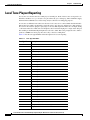
Local Tone Playout Reporting
6
10
Obtaining Network Status Prior to Getting IP Connectivity
11
Cisco ATA 186 and Cisco ATA 188 Analog Telephone Adaptor Administrator’s Guide for SCCP (version 3.0)
OL-4652-01
vii
Contents
Obtaining Network Status After Getting IP Connectivity
DHCP Status HTML Page
13
Real-Time Transport Protocol (RTP) Statistics Reporting
The nptcap Tool
13
14
Frequently Asked Questions
Contacting TAC
12
14
16
How to Use Pre-call and Mid-call Services
1
Procedures for Using Pre-call Services 1
Access Voicemail 2
Change Your Pre-Call Service Access Code
Activate Call-Forward-All 2
Cancel Call-Forward-All 2
Redial 2
Speed Dial 3
Call Pickup 3
Group Call Pickup 3
MeetMe Conference 4
2
Procedures for Using Mid-call Services 4
Bellcore Style 4
Bellcore Style Call Transfer Procedure 4
Bellcore Style Conference Call Procedure 5
Cisco VG248 Style 5
Cisco VG248 Style Three-way Calling Procedure 5
Cisco VG248 Call Transfer Procedure 5
Cisco VG248 Conference Call Procedure 6
Cisco ATA Style 6
Cisco ATA Style Call Hold/Resume Procedure 6
Cisco ATA Style Call Transfer Procedure 7
Cisco ATA Style Conference Calling Procedure 7
Voice Menu Codes
1
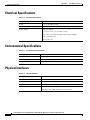
Cisco ATA Specifications
Physical Specifications
Electrical Specifications
1
1
2
Environmental Specifications
Physical Interfaces
2
2
Cisco ATA 186 and Cisco ATA 188 Analog Telephone Adaptor Administrator’s Guide for SCCP (version 3.0)
viii
OL-4652-01
Contents
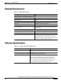
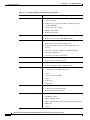
Ringing Characteristics
Software Specifications
3
3
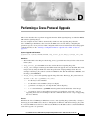
Performing a Cross-Protocol Upgrade
1
Recommended Cisco ATA Tone Parameter Values by Country
1
GLOSSARY
INDEX
Cisco ATA 186 and Cisco ATA 188 Analog Telephone Adaptor Administrator’s Guide for SCCP (version 3.0)
OL-4652-01
ix
Contents
Cisco ATA 186 and Cisco ATA 188 Analog Telephone Adaptor Administrator’s Guide for SCCP (version 3.0)
x
OL-4652-01
Preface
Overview
The Cisco ATA 186 and Cisco ATA 188 Analog Telephone Adaptor Administrator’s Guide for SCCP
(version 3.0) provides the information you need to install, configure and manage the Cisco ATA 186 and
Cisco ATA 188 on a Skinny Client Control Protocol (SCCP) network.
This guide does not cover information related to the implementation of an SCCP Voice over IP (VoIP)
network.
Note
The term Cisco ATA is used throughout this manual to refer to both the Cisco ATA 186 and the
Cisco ATA 188, unless differences between the Cisco ATA 186 and Cisco ATA 188 are explicitly
stated.
Audience
This guide is intended mainly for service providers and network administrators who administer VoIP
services using the Cisco ATA. Many of these tasks impact the ability of the Cisco ATA to function on
the network, and require an understanding of IP networking and telephony concepts. However, some
end-user procedures are included where necessary with instructions to the administrator about how to
provide the end user with the pertinent information.
Organization
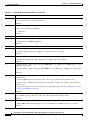
Table 1 provides an overview of the organization of this guide.
Table 1
Cisco ATA 186 and Cisco ATA 188 Analog Telephone Administrator’s Guide (SCCP) Organization
Chapter
Description
Chapter 1, “Cisco Analog Telephone Adaptor Overview”
Provides descriptions of hardware and software features of
the Cisco ATA Analog Telephone Adaptor along with a brief
overview of the Skinny Client Control Protocol (SCCP).
Chapter 2, “Installing the Cisco ATA”
Provides information about installing the Cisco ATA.
Cisco ATA 186 and Cisco ATA 188 Analog Telephone Adaptor Administrator’s Guide for SCCP (version 3.0)
OL-4652-01
xi
Preface
Conventions
Table 1
Cisco ATA 186 and Cisco ATA 188 Analog Telephone Administrator’s Guide (SCCP) Organization (continued)
Chapter
Description
Chapter 3, “Configuring the Cisco ATA for SCCP”
Provides information about how to configure the Cisco ATA
and the different configuration methods you can use.
Chapter 4, “Adding the Cisco ATA to the
Cisco CallManager”
Provides information about adding the Cisco ATA to the
Cisco CallManager environment.
Chapter 5, “Parameters and Defaults”
Provides information on the parameters and defaults that you
can use to configure the Cisco ATA.
Chapter 6, “Configuring and Debugging Fax Services”
Provides instructions for configuring both ports of the
Cisco ATA to support fax transmission.
Chapter 7, “Upgrading the Cisco ATA Signaling Image.”
Provides instructions for remotely upgrading Cisco ATA
software.
Chapter 8, “Troubleshooting”
Provides basic testing and troubleshooting procedures for the
Cisco ATA.
Appendix A, “How to Use Pre-call and Mid-call Services”
Provides end-user procedures on how to use pre-call services
and mid-call services that the Cisco ATA supports.
Appendix B, “Voice Menu Codes”
Provides a quick-reference list of the voice configuration
menu options for the Cisco ATA.
Appendix C, “Cisco ATA Specifications”
Provides physical specifications for the Cisco ATA.
Appendix D, “Performing a Cross-Protocol Upgrade”
Provides instructions on changing from SCCP to a SIP,
MGCP or H.323 signaling image.
Appendix E, “Recommended Cisco ATA Tone Parameter
Values by Country”
Provides tone parameters for various countries.
Glossary
Provides definitions of commonly used terms.
Index
Provides reference information.
Conventions
This document uses the following conventions:
Note
•
Alternative keywords are grouped in braces and separated by vertical bars (for example, {x | y | z}).
•
Arguments for which you supply values are in italic font.
•
Commands and keywords are in boldface font.
•
Elements in square brackets ([ ]) are optional.
•
Information you must enter is in boldface screen font.
•
Optional alternative keywords are grouped in brackets and separated by vertical bars (for example,
[x | y | z]).
•
Terminal sessions and information the system displays are in screen font.
Means reader take note. Notes contain helpful suggestions or references to material not covered in the
publication.
Cisco ATA 186 and Cisco ATA 188 Analog Telephone Adaptor Administrator’s Guide for SCCP (version 3.0)
xii
OL-4652-01
Preface
Conventions
Timesaver
Tip
Caution
Warning
Means the described action saves time. You can save time by performing the action described in the
paragraph.
Means the following information will help you solve a problem. The tips information might not be
troubleshooting or even an action, but could be useful information, similar to a Timesaver.
Means reader be careful. In this situation, you might do something that could result in equipment
damage or loss of data.
IMPORTANT SAFETY INSTRUCTIONS
This warning symbol means danger. You are in a situation that could cause bodily injury. Before you
work on any equipment, be aware of the hazards involved with electrical circuitry and be familiar
with standard practices for preventing accidents. Use the statement number provided at the end of
each warning to locate its translation in the translated safety warnings that accompanied this
device. Statement 1071
SAVE THESE INSTRUCTIONS
Waarschuwing
BELANGRIJKE VEILIGHEIDSINSTRUCTIES
Dit waarschuwingssymbool betekent gevaar. U verkeert in een situatie die lichamelijk letsel kan
veroorzaken. Voordat u aan enige apparatuur gaat werken, dient u zich bewust te zijn van de bij
elektrische schakelingen betrokken risico's en dient u op de hoogte te zijn van de standaard
praktijken om ongelukken te voorkomen. Gebruik het nummer van de verklaring onderaan de
waarschuwing als u een vertaling van de waarschuwing die bij het apparaat wordt geleverd, wilt
raadplegen.
BEWAAR DEZE INSTRUCTIES
Varoitus
TÄRKEITÄ TURVALLISUUSOHJEITA
Tämä varoitusmerkki merkitsee vaaraa. Tilanne voi aiheuttaa ruumiillisia vammoja. Ennen kuin
käsittelet laitteistoa, huomioi sähköpiirien käsittelemiseen liittyvät riskit ja tutustu
onnettomuuksien yleisiin ehkäisytapoihin. Turvallisuusvaroitusten käännökset löytyvät laitteen
mukana toimitettujen käännettyjen turvallisuusvaroitusten joukosta varoitusten lopussa näkyvien
lausuntonumeroiden avulla.
SÄILYTÄ NÄMÄ OHJEET
Cisco ATA 186 and Cisco ATA 188 Analog Telephone Adaptor Administrator’s Guide for SCCP (version 3.0)
OL-4652-01
xiii
Preface
Conventions
Attention
IMPORTANTES INFORMATIONS DE SÉCURITÉ
Ce symbole d'avertissement indique un danger. Vous vous trouvez dans une situation pouvant
entraîner des blessures ou des dommages corporels. Avant de travailler sur un équipement, soyez
conscient des dangers liés aux circuits électriques et familiarisez-vous avec les procédures
couramment utilisées pour éviter les accidents. Pour prendre connaissance des traductions des
avertissements figurant dans les consignes de sécurité traduites qui accompagnent cet appareil,
référez-vous au numéro de l'instruction situé à la fin de chaque avertissement.
CONSERVEZ CES INFORMATIONS
Warnung
WICHTIGE SICHERHEITSHINWEISE
Dieses Warnsymbol bedeutet Gefahr. Sie befinden sich in einer Situation, die zu Verletzungen führen
kann. Machen Sie sich vor der Arbeit mit Geräten mit den Gefahren elektrischer Schaltungen und
den üblichen Verfahren zur Vorbeugung vor Unfällen vertraut. Suchen Sie mit der am Ende jeder
Warnung angegebenen Anweisungsnummer nach der jeweiligen Übersetzung in den übersetzten
Sicherheitshinweisen, die zusammen mit diesem Gerät ausgeliefert wurden.
BEWAHREN SIE DIESE HINWEISE GUT AUF.
Avvertenza
IMPORTANTI ISTRUZIONI SULLA SICUREZZA
Questo simbolo di avvertenza indica un pericolo. La situazione potrebbe causare infortuni alle
persone. Prima di intervenire su qualsiasi apparecchiatura, occorre essere al corrente dei pericoli
relativi ai circuiti elettrici e conoscere le procedure standard per la prevenzione di incidenti.
Utilizzare il numero di istruzione presente alla fine di ciascuna avvertenza per individuare le
traduzioni delle avvertenze riportate in questo documento.
CONSERVARE QUESTE ISTRUZIONI
Advarsel
VIKTIGE SIKKERHETSINSTRUKSJONER
Dette advarselssymbolet betyr fare. Du er i en situasjon som kan føre til skade på person. Før du
begynner å arbeide med noe av utstyret, må du være oppmerksom på farene forbundet med
elektriske kretser, og kjenne til standardprosedyrer for å forhindre ulykker. Bruk nummeret i slutten
av hver advarsel for å finne oversettelsen i de oversatte sikkerhetsadvarslene som fulgte med denne
enheten.
TA VARE PÅ DISSE INSTRUKSJONENE
Aviso
INSTRUÇÕES IMPORTANTES DE SEGURANÇA
Este símbolo de aviso significa perigo. Você está em uma situação que poderá ser causadora de
lesões corporais. Antes de iniciar a utilização de qualquer equipamento, tenha conhecimento dos
perigos envolvidos no manuseio de circuitos elétricos e familiarize-se com as práticas habituais de
prevenção de acidentes. Utilize o número da instrução fornecido ao final de cada aviso para
localizar sua tradução nos avisos de segurança traduzidos que acompanham este dispositivo.
GUARDE ESTAS INSTRUÇÕES
Cisco ATA 186 and Cisco ATA 188 Analog Telephone Adaptor Administrator’s Guide for SCCP (version 3.0)
xiv
OL-4652-01
Preface
Conventions
¡Advertencia!
INSTRUCCIONES IMPORTANTES DE SEGURIDAD
Este símbolo de aviso indica peligro. Existe riesgo para su integridad física. Antes de manipular
cualquier equipo, considere los riesgos de la corriente eléctrica y familiarícese con los
procedimientos estándar de prevención de accidentes. Al final de cada advertencia encontrará el
número que le ayudará a encontrar el texto traducido en el apartado de traducciones que acompaña
a este dispositivo.
GUARDE ESTAS INSTRUCCIONES
Varning!
VIKTIGA SÄKERHETSANVISNINGAR
Denna varningssignal signalerar fara. Du befinner dig i en situation som kan leda till personskada.
Innan du utför arbete på någon utrustning måste du vara medveten om farorna med elkretsar och
känna till vanliga förfaranden för att förebygga olyckor. Använd det nummer som finns i slutet av
varje varning för att hitta dess översättning i de översatta säkerhetsvarningar som medföljer denna
anordning.
SPARA DESSA ANVISNINGAR
Cisco ATA 186 and Cisco ATA 188 Analog Telephone Adaptor Administrator’s Guide for SCCP (version 3.0)
OL-4652-01
xv
Preface
Related Documentation
Related Documentation
•
Cisco ATA 186 and Cisco 188 Analog Telephone Adaptor At a Glance
•
Regulatory Compliance and Safety Information for the Cisco ATA 186 and Cisco 188
•
Cisco ATA Release Notes
•
Configuring Cisco IP Phones, Users, and Features in Cisco CallManager
•
Cisco IP Phone Administration Guide for Cisco CallManager
•
Cisco IOS Telephony Service documentation
Obtaining Documentation
Cisco provides several ways to obtain documentation, technical assistance, and other technical
resources. These sections explain how to obtain technical information from Cisco Systems.
Cisco.com
You can access the most current Cisco documentation on the World Wide Web at this URL:
http://www.cisco.com/univercd/home/home.htm
You can access the Cisco website at this URL:
http://www.cisco.com
International Cisco web sites can be accessed from this URL:
http://www.cisco.com/public/countries_languages.shtml
Cisco ATA 186 and Cisco ATA 188 Analog Telephone Adaptor Administrator’s Guide for SCCP (version 3.0)
xvi
OL-4652-01
Preface
Obtaining Documentation
Documentation CD-ROM
Cisco documentation and additional literature are available in a Cisco Documentation CD-ROM
package, which may have shipped with your product. The Documentation CD-ROM is updated monthly
and may be more current than printed documentation. The CD-ROM package is available as a single unit
or through an annual subscription.
Registered Cisco.com users can order the Documentation CD-ROM (product number
DOC-CONDOCCD=) through the online Subscription Store:
http://www.cisco.com/go/subscription
Ordering Documentation
You can find instructions for ordering documentation at this URL:
http://www.cisco.com/univercd/cc/td/doc/es_inpck/pdi.htm
You can order Cisco documentation in these ways:
•
Registered Cisco.com users (Cisco direct customers) can order Cisco product documentation from
the Networking Products MarketPlace:
http://www.cisco.com/en/US/partner/ordering/index.shtml
•
Registered Cisco.com users can order the Documentation CD-ROM (Customer Order Number
DOC-CONDOCCD=) through the online Subscription Store:
http://www.cisco.com/go/subscription
•
Nonregistered Cisco.com users can order documentation through a local account representative by
calling Cisco Systems Corporate Headquarters (California, U.S.A.) at 408 526-7208 or, elsewhere
in North America, by calling 800 553-NETS (6387).
Documentation Feedback
You can submit comments electronically on Cisco.com. On the Cisco Documentation home page, click
Feedback at the top of the page.
You can e-mail your comments to [email protected].
You can submit your comments by mail by using the response card behind the front cover of your
document or by writing to the following address:
Cisco Systems
Attn: Customer Document Ordering
170 West Tasman Drive
San Jose, CA 95134-9883
We appreciate your comments.
Cisco ATA 186 and Cisco ATA 188 Analog Telephone Adaptor Administrator’s Guide for SCCP (version 3.0)
OL-4652-01
xvii
Preface
Obtaining Technical Assistance
Obtaining Technical Assistance
Cisco provides Cisco.com, which includes the Cisco Technical Assistance Center (TAC) Website, as a
starting point for all technical assistance. Customers and partners can obtain online documentation,
troubleshooting tips, and sample configurations from the Cisco TAC website. Cisco.com registered
users have complete access to the technical support resources on the Cisco TAC website, including TAC
tools and utilities.
Cisco.com
Cisco.com offers a suite of interactive, networked services that let you access Cisco information,
networking solutions, services, programs, and resources at any time, from anywhere in the world.
Cisco.com provides a broad range of features and services to help you with these tasks:
•
Streamline business processes and improve productivity
•
Resolve technical issues with online support
•
Download and test software packages
•
Order Cisco learning materials and merchandise
•
Register for online skill assessment, training, and certification programs
To obtain customized information and service, you can self-register on Cisco.com at this URL:
http://www.cisco.com
Technical Assistance Center
The Cisco TAC is available to all customers who need technical assistance with a Cisco product,
technology, or solution. Two levels of support are available: the Cisco TAC website and the Cisco TAC
Escalation Center. The avenue of support that you choose depends on the priority of the problem and the
conditions stated in service contracts, when applicable.
We categorize Cisco TAC inquiries according to urgency:
•
Priority level 4 (P4)—You need information or assistance concerning Cisco product capabilities,
product installation, or basic product configuration.
•
Priority level 3 (P3)—Your network performance is degraded. Network functionality is noticeably
impaired, but most business operations continue.
•
Priority level 2 (P2)—Your production network is severely degraded, affecting significant aspects
of business operations. No workaround is available.
•
Priority level 1 (P1)—Your production network is down, and a critical impact to business operations
will occur if service is not restored quickly. No workaround is available.
Cisco TAC Website
You can use the Cisco TAC website to resolve P3 and P4 issues yourself, saving both cost and time. The
site provides around-the-clock access to online tools, knowledge bases, and software. To access the
Cisco TAC website, go to this URL:
http://www.cisco.com/tac
Cisco ATA 186 and Cisco ATA 188 Analog Telephone Adaptor Administrator’s Guide for SCCP (version 3.0)
xviii
OL-4652-01
Preface
Obtaining Additional Publications and Information
All customers, partners, and resellers who have a valid Cisco service contract have complete access to
the technical support resources on the Cisco TAC website. Some services on the Cisco TAC website
require a Cisco.com login ID and password. If you have a valid service contract but do not have a login
ID or password, go to this URL to register:
http://tools.cisco.com/RPF/register/register.do
If you are a Cisco.com registered user, and you cannot resolve your technical issues by using the Cisco
TAC website, you can open a case online at this URL:
http://www.cisco.com/en/US/support/index.html
If you have Internet access, we recommend that you open P3 and P4 cases through the Cisco TAC
website so that you can describe the situation in your own words and attach any necessary files.
Cisco TAC Escalation Center
The Cisco TAC Escalation Center addresses priority level 1 or priority level 2 issues. These
classifications are assigned when severe network degradation significantly impacts business operations.
When you contact the TAC Escalation Center with a P1 or P2 problem, a Cisco TAC engineer
automatically opens a case.
To obtain a directory of toll-free Cisco TAC telephone numbers for your country, go to this URL:
http://www.cisco.com/warp/public/687/Directory/DirTAC.shtml
Before calling, please check with your network operations center to determine the level of Cisco support
services to which your company is entitled: for example, SMARTnet, SMARTnet Onsite, or Network
Supported Accounts (NSA). When you call the center, please have available your service agreement
number and your product serial number.
Obtaining Additional Publications and Information
Information about Cisco products, technologies, and network solutions is available from various online
and printed sources.
•
The Cisco Product Catalog describes the networking products offered by Cisco Systems as well as
ordering and customer support services. Access the Cisco Product Catalog at this URL:
http://www.cisco.com/en/US/products/products_catalog_links_launch.html
•
Cisco Press publishes a wide range of networking publications. Cisco suggests these titles for new
and experienced users: Internetworking Terms and Acronyms Dictionary, Internetworking
Technology Handbook, Internetworking Troubleshooting Guide, and the Internetworking Design
Guide. For current Cisco Press titles and other information, go to Cisco Press online at this URL:
http://www.ciscopress.com
•
Packet magazine is the Cisco monthly periodical that provides industry professionals with the latest
information about the field of networking. You can access Packet magazine at this URL:
http://www.cisco.com/en/US/about/ac123/ac114/about_cisco_packet_magazine.html
•
iQ Magazine is the Cisco monthly periodical that provides business leaders and decision makers
with the latest information about the networking industry. You can access iQ Magazine at this URL:
http://business.cisco.com/prod/tree.taf%3fasset_id=44699&public_view=true&kbns=1.html
Cisco ATA 186 and Cisco ATA 188 Analog Telephone Adaptor Administrator’s Guide for SCCP (version 3.0)
OL-4652-01
xix
Preface
Obtaining Additional Publications and Information
•
Internet Protocol Journal is a quarterly journal published by Cisco Systems for engineering
professionals involved in the design, development, and operation of public and private internets and
intranets. You can access the Internet Protocol Journal at this URL:
http://www.cisco.com/en/US/about/ac123/ac147/about_cisco_the_internet_protocol_journal.html
•
Training—Cisco offers world-class networking training, with current offerings in network training
listed at this URL:
http://www.cisco.com/en/US/learning/le31/learning_recommended_training_list.html
Cisco ATA 186 and Cisco ATA 188 Analog Telephone Adaptor Administrator’s Guide for SCCP (version 3.0)
xx
OL-4652-01
C H A P T E R
1
Cisco Analog Telephone Adaptor Overview
This section describes the hardware and software features of the Cisco Analog Telephone Adaptor
(Cisco ATA) and includes a brief overview of the Skinny Client Control Protocol (SCCP).
The Cisco ATA analog telephone adaptors are handset-to-Ethernet adaptors that allow regular analog
telephones to operate on IP-based telephony networks. Cisco ATAs support two voice ports, each with
an independent telephone number. The Cisco ATA 188 also has an RJ-45 10/100BASE-T data port.
This section covers the following topics:
•
Overview of the Skinny Client Control Protocol, page 1-2
•
Hardware Overview, page 1-3
•
Software Features, page 1-5
•
Installation and Configuration Overview, page 1-9
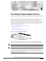
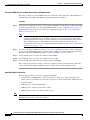
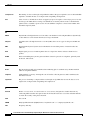
Figure 1-1
Cisco ATA Analog Telephone Adaptor
CISCO A
TA 186
TELEPH
ONE AD
APTOR
72209
ANALOG
The Cisco ATA, which operates with Cisco voice-packet gateways, uses broadband pipes deployed
through digital subscriber line (DSL), fixed wireless, cable modem, and other Ethernet connections.
Note
The term Cisco ATA refers to both the Cisco ATA 186 and the Cisco ATA 188, unless otherwise stated.
Note
This guide provides information about the SCCP image for the Cisco ATA. The features and functionality
described in this guide do not necessarily pertain to the features and functionality provided by the other
protocol loads available for the Cisco ATA. Each protocol load has its own administrator’s guide. If you are
looking for information about the behavior of the Cisco ATA for a protocol other than SCCP, please refer to
the administrator’s guide specific to that protocol.
Cisco ATA 186 and Cisco ATA 188 Analog Telephone Adaptor Administrator’s Guide for SCCP (version 3.0)
OL-4652-01
1-1
Chapter 1
Cisco Analog Telephone Adaptor Overview
Overview of the Skinny Client Control Protocol
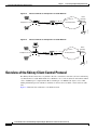
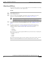
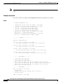
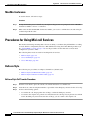
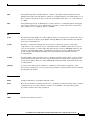
Figure 1-2
The Cisco ATA 186 as an Endpoint in an SCCP Network
Voice
gateway
Layer 3
Telephone or fax
V
IP infrastructure
V
PSTN
Cisco CallManager
82049
Ethernet
Cisco ATA 186
Figure 1-3
The Cisco ATA 188 as an Endpoint in an SCCP Network
Voice
gateway
Layer 3
Telephone or fax
V
IP infrastructure
V
PSTN
Cisco CallManager
82050
Ethernet
Cisco ATA 188
Overview of the Skinny Client Control Protocol
The Skinny Client Control Protocol (SCCP) is the Cisco standard for real-time calls and conferencing
over Internet Protocol (IP). With SCCP, Cisco IP Phones can co-exist in an H.323 environment. When
a Cisco CallManager is coupled with an H.323 Gatekeeper or an MGCP Call Agent, a Cisco ATA
running SCCP interoperates with H.323 terminals on the far end to establish, control and clear audio
calls.
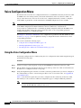
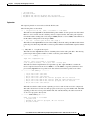
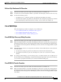
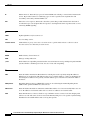
Figure 1-4 illustrates the architecture of an SCCP network.
Cisco ATA 186 and Cisco ATA 188 Analog Telephone Adaptor Administrator’s Guide for SCCP (version 3.0)
1-2
OL-4652-01
Chapter 1
Cisco Analog Telephone Adaptor Overview
Hardware Overview
Figure 1-4
SCCP Architecture
Skinny client
phone-2
H.323 compliant
terminal
IP gateway
External
Internet
Internal
IP Intranet
Skinny client
phone-1
Cisco ATA 186
H.323 compliant
terminal
82051
V
Cisco CallManager
H.323 compliant
terminal
Telephone or fax
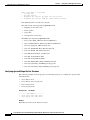
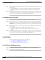
Hardware Overview
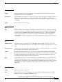
Cisco ATAs are compact, easy-to-install devices. Figure 1-5 shows the rear panel of the
Cisco ATA 186. Figure 1-6 shows the rear panel of the Cisco ATA 188.
PHONE 2
10BaseT
ACT
PHONE 1
5V
Power
connector
RJ-11 FXS ports
RJ-45 10BaseT
Figure 1-6
72210
PHONE 1
Cisco ATA 186—Rear View
ACT LED
Cisco ATA 188—Rear View
PHONE 2
RJ-11 FXS ports
LINK
10/100 PC
10/100 UPLINK LINK
72211
Figure 1-5
5V
Power
connector
LINK LED
LINK LED
RJ-45 10/100BaseT ports
Cisco ATA 186 and Cisco ATA 188 Analog Telephone Adaptor Administrator’s Guide for SCCP (version 3.0)
OL-4652-01
1-3
Chapter 1
Cisco Analog Telephone Adaptor Overview
Hardware Overview
The unit provides the following connectors and indicators:
•
5V power connector.
•
Two RJ-11 FXS (Foreign Exchange Station) ports—The Cisco ATA supports two independent
RJ-11 telephone ports that can connect to any standard analog telephone device. Each port supports
either voice calls or fax sessions, and both ports can be used simultaneously.
Note
•
The Cisco ATA186-I1 and Cisco ATA188-I1 provide 600-ohm resistive impedance. The Cisco
ATA186-I2 and Cisco ATA188-I2 provide 270 ohm + 750 ohm // 150-nF complex impedance.
The impedance option is requested when you place your order and should match your specific
application. If you are not sure of the applicable configuration, check your country or regional
telephone impedance requirements.
Ethernet ports
– The Cisco ATA 186 has one RJ-45 10BASE-T uplink Ethernet port to connect the
Cisco ATA 186 to a 10/100BASE-T hub or another Ethernet device.
– The Cisco ATA 188 has two Ethernet ports: an RJ-45 10/100BASE-T uplink port to connect the
Cisco ATA 188 to a 10/100BASE-T hub or another Ethernet device and an RJ-45
10/100BASE-T data port to connect an Ethernet-capable device, such as a computer, to the
network.
Note
The Cisco ATA 188 performs auto-negotiation for duplexity and speed and is capable of 10/100
Mbps, full-duplex operation. The Cisco ATA 186 is fixed at 10 Mbps, half-duplex operation.
•
The Cisco ATA 188 RJ-45 LED shows network link and activity. The LED blinks twice when the
Cisco ATA is first powered on, then turns off if there is no link or activity. The LED blinks to show
network activity and is solid when there is a link.
•
The Cisco ATA 186 RJ-45 LED is solid when the Cisco ATA is powered on and blinks to show
network activity.
•
Function button—The function button is located on the top panel of the unit (see Figure 1-7).
Figure 1-7
Function Button
Function
button
CISCO
72214
ATA 186
ANALOG
TELEPH
ONE AD
APTOR
The function button lights when you pick up the handset of a telephone attached to the Cisco ATA.
The button blinks quickly when the Cisco ATA is upgrading its configuration.
Cisco ATA 186 and Cisco ATA 188 Analog Telephone Adaptor Administrator’s Guide for SCCP (version 3.0)
1-4
OL-4652-01
Chapter 1
Cisco Analog Telephone Adaptor Overview
Software Features
Note
If the function button blinks slowly, the Cisco ATA cannot find the DHCP server. Check your
Ethernet connections and make sure the DHCP server is available.
Pressing the function button allows you to access to the voice configuration menu. For additional
information about the voice configuration menu, see the “Voice Configuration Menu” section on
page 3-22.
Caution
Never press the function button during an upgrade process. Doing so may interfere with the process.
Software Features
This section contains topics that cover the protocols and services that the Cisco ATA supports:
•
SCCP Version, page 1-5
•
Voice Codecs Supported, page 1-5
•
Additional Supported Signaling Protocols, page 1-6
•
Other Supported Protocols, page 1-6
•
Basic Services, page 1-6
•
Fax Services, page 1-7
•
Pre-call and Mid-call Services, page 1-7
SCCP Version
The Cisco ATA supports the Skinny Client Control Protocol (SCCP) Rev. 3.0 and 3.1.
Voice Codecs Supported
The Cisco ATA supports the following voice codecs (check your other network devices for the codecs
they support):
•
G.711µ-law
•
G.711A-law
•
G.723.1
•
G.729
•
G.729A
•
G.729B
•
G.729AB
When operating with a low-bit-rate codec, the Cisco ATA can support either two G.723.1 connections
or one G.729 connection. The selection of G.723.1 or G.729 must be statically configured. When
G.723.1 is the low-bit-rate codec, each FXS port is allocated with one G.723.1 connection. When G.729
is used, only one FXS port can use G.729. For more information, see the “LBRCodec” section on
page 5-13 and “ConnectMode” section on page 5-21.
Cisco ATA 186 and Cisco ATA 188 Analog Telephone Adaptor Administrator’s Guide for SCCP (version 3.0)
OL-4652-01
1-5
Chapter 1
Cisco Analog Telephone Adaptor Overview
Software Features
Additional Supported Signaling Protocols
In addition to SCCP, the Cisco ATA supports the following signaling protocols:
•
Media Gateway Control Protocol (MGCP)
•
H.323
•
Session Initiation Protocol (SIP)
If you wish to perform a cross-protocol upgrade from SCCP to another signaling image, see Appendix D,
“Performing a Cross-Protocol Upgrade.”
Other Supported Protocols
Other protocols that the Cisco ATA supports include the following:
•
802.1Q VLAN tagging
•
Cisco Discovery Protocol (CDP)
•
Domain Name System (DNS)
•
Dynamic Host Configuration Protocol (DHCP)
•
Internet Control Message Protocol (ICMP)
•
Internet Protocol (IP)
•
Real-Time Transport Protocol (RTP)
•
Transmission Control Protocol (TCP)
•
Trivial File Transfer Protocol (TFTP)
•
User Datagram Protocol (UDP)
Basic Services
For an alphabetical list of Cisco ATA basic services and the parameters for configuring each service, see
Table 3-5 on page 3-8.
These services include the following features:
•
Configurable tone (dial tone, busy tone, confirm tone, reorder tone, call waiting tone)
•
IP address assignment—DHCP-provided or statically configured
•
Cisco ATA configuration by means of the Cisco CallManager TFTP server, web browser, or voice
configuration menu.
•
VLAN configuration
•
Caller ID format
•
Ring cadence format
•
Distinctive ring (external calls have two rings with a short pause between rings)
•
Silence suppression
•
Low-bit-rate codec selection
•
RTP media port configuration
Cisco ATA 186 and Cisco ATA 188 Analog Telephone Adaptor Administrator’s Guide for SCCP (version 3.0)
1-6
OL-4652-01
Chapter 1
Cisco Analog Telephone Adaptor Overview
Software Features
•
Hook-flash detection timing configuration
•
Cisco Discovery Protocol (CDP)
•
User interface password
•
Type of Service (ToS) configuration for audio and signaling ethernet packets
•
802.1P Class of Service (Cos) Bit configuration
•
Debugging and diagnostic tools
Fax Services
The Cisco ATA supports two modes of fax services, in which fax signals are transmitted using the G.711
codec:
•
Fax pass-through mode—Receiver-side Called Station Identification (CED) tone detection with
automatic G.711A-law or G.711µ-law switching.
•
Fax mode—The Cisco ATA is configured as a G.711-only device.
How you set Cisco ATA fax parameters depends on what network gateways are being used. You may
need to modify the default fax parameter values (see Chapter 6, “Configuring and Debugging Fax
Services”).
Note
Success of fax transmission depends on network conditions and fax modem response to these conditions.
The network must have reasonably low network jitter, network delay, and packet loss rate.
Pre-call and Mid-call Services
This section provides an overview of telephone services that the Cisco ATA allows the user to perform
either before or during a call. For end-user procedures on how to use these services, see Appendix A,
“How to Use Pre-call and Mid-call Services.”
This section contains the following topics:
Note
•
Pre-call Services, page 1-7
•
Mid-call Services, page 1-8
The services listed in this section are supported by Cisco CallManager. For Cisco IOS Telephony
Service (ITS)-supported services, refer to ITS documentation.
Pre-call Services
Table 1-1 lists the pre-call services that the Cisco ATA supports for the SCCP protocol. Table 1-1 also
includes references to where the user procedure is described for each service.
Cisco ATA 186 and Cisco ATA 188 Analog Telephone Adaptor Administrator’s Guide for SCCP (version 3.0)
OL-4652-01
1-7
Chapter 1
Cisco Analog Telephone Adaptor Overview
Software Features
Table 1-1
Pre-call Services and Where to Find End-user Procedures
Service
Procedure Reference
Voice mail access
Access Voicemail, page A-2
Change access code
Change Your Pre-Call Service Access Code, page
A-2
Forward all calls to another number
Activate Call-Forward-All, page A-2
Cancel the forwarding of all calls
Cancel Call-Forward-All, page A-2
Redial the most recent number dialed
Redial, page A-2
Use speed dial
Speed Dial, page A-3
Answer a call in your call-pickup group
Call Pickup, page A-3
Answer a call outside of your call-pickup group
Group Call Pickup, page A-3
Set up a conference
MeetMe Conference, page A-4
Mid-call Services
The method of initiating and using mid-call services for the SCCP protocol differs according to mode.
The following three modes are available for invoking mid-call services:
•
Bellcore Style (default)
•
Cisco VG248 Style
•
Cisco ATA Style
The mode can be configured using bits 28 and 29 of the ConnectMode parameter (see the
“ConnectMode” section on page 5-21).
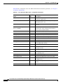
Table 1-2 lists the mid-call services that the Cisco ATA supports for each of the three modes. Table 1-2
also includes references to where the end-user procedure is described for each service.
Table 1-2
Mid-call Services and Where to Find End-user Procedures
Style and Related Services
Procedure Reference
Bellcore style (default) services:
Bellcore Style, page A-4
•
Call transfer
•
Conference call
Cisco VG248 style services:
•
Three-way call
•
Call transfer
•
Conference call
Cisco ATA style services:
•
Call hold/resume
•
Call transfer
•
Conference call
Cisco VG248 Style, page A-5
Cisco ATA Style, page A-6
Cisco ATA 186 and Cisco ATA 188 Analog Telephone Adaptor Administrator’s Guide for SCCP (version 3.0)
1-8
OL-4652-01
Chapter 1
Cisco Analog Telephone Adaptor Overview
Installation and Configuration Overview
Installation and Configuration Overview
Table 1-3 provides the basic steps required to install and configure the Cisco ATA to make it operational
in a typical Cisco CallManager environment.
Table 1-3
Overview of the Steps Required to Install and Configure the Cisco ATA and Make it Operational
Action
Reference
1.
Plan the network and Cisco ATA configuration.
2.
Install the Ethernet connection.
3.
Install and configure the other network devices.
4.
Install the Cisco ATA but do not power up the Cisco ATA
yet.
Note
If you power up the Cisco ATA before adding the
Cisco ATA to the Cisco CallManager, you will need to
perform a reset once you have added the Cisco ATA to
the Cisco CallManager.
What the Cisco ATA Package Includes, page 2-2
Resetting the Cisco ATA Using Cisco CallManager, page
3-26
5.
Download the desired Cisco ATA release software zip file
from the Cisco web site, then configure the Cisco ATA.
Chapter 3, “Configuring the Cisco ATA for SCCP”
6.
Add the Cisco ATA to the Cisco CallManager.
Chapter 4, “Adding the Cisco ATA to the
Cisco CallManager”
7.
Power up the Cisco ATA.
8.
Periodically, you can upgrade an individual Cisco ATA or
all Cisco ATAs to a new signaling image by using the
Cisco CallManager administration web pages.
Chapter 7, “Upgrading the Cisco ATA Signaling Image”
Cisco ATA 186 and Cisco ATA 188 Analog Telephone Adaptor Administrator’s Guide for SCCP (version 3.0)
OL-4652-01
1-9
Chapter 1
Cisco Analog Telephone Adaptor Overview
Installation and Configuration Overview
Cisco ATA 186 and Cisco ATA 188 Analog Telephone Adaptor Administrator’s Guide for SCCP (version 3.0)
1-10
OL-4652-01
C H A P T E R
2
Installing the Cisco ATA
This section provides instructions for installing the Cisco ATA 186 and Cisco ATA 188. Before you
perform the installation, make sure you have met the following prerequisites:
•
Planned the network and Cisco ATA configuration.
•
Installed the Ethernet connection.
•
Installed and configured the other network devices.
This section contains the following topics:
Note
•
Network Requirements, page 2-2
•
Safety Recommendations, page 2-2
•
What the Cisco ATA Package Includes, page 2-2
•
What You Need, page 2-3
•
Installation Procedure, page 2-3
•
Power-Down Procedure, page 2-6
The term Cisco ATA is used throughout this manual to refer to both the Cisco ATA 186 and the
Cisco ATA 188, unless differences between the Cisco ATA 186 and Cisco ATA 188 are explicitly
stated.
Cisco ATA 186 and Cisco ATA 188 Analog Telephone Adaptor Administrator’s Guide for SCCP (version 3.0)
OL-4652-01
2-1
Chapter 2
Installing the Cisco ATA
Network Requirements
Network Requirements
The Cisco ATA acts as an endpoint on an IP telephony network. The following equipment is required:
•
Cisco CallManager version 3.0 or later
•
Voice packet gateway—Required if you are connecting to the Public Switched Telephone Network
(PSTN)
•
Ethernet connection
Safety Recommendations
To ensure general safety, follow these guidelines:
•
Do not get this product wet or pour liquids into this device.
•
Do not open or disassemble this product.
•
Do not perform any action that creates a potential hazard to people or makes the equipment unsafe.
•
Use only the power supply that comes with the Cisco ATA.
Warning
Ultimate disposal of this product should be handled according to all national laws and regulations.
Warning
Read the installation instructions before you connect the system to its power source.
Warning
The plug-socket combination must be accessible at all times because it serves as the main
disconnecting device.
Warning
Do not work on the system or connect or disconnect cables during periods of lightning activity.
Warning
To avoid electric shock, do not connect safety extra-low voltage (SELV) circuits to telephone-network
voltage (TNV) circuits. LAN ports contain SELV circuits, and WAN ports contain TNV circuits. Some
LAN and WAN ports both use RJ-45 connectors. Use caution when connecting cables.
For translated warnings, see the Regulatory Compliance and Safety Information for the Cisco ATA 186
and Cisco ATA 188 manual.
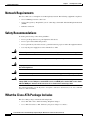
What the Cisco ATA Package Includes
The Cisco ATA package contains the following items:
•
Cisco ATA 186 or Cisco ATA 188 Analog Telephone Adaptor
•
Cisco ATA 186 and Cisco ATA 188 Analog Telephone Adaptor at a Glance
Cisco ATA 186 and Cisco ATA 188 Analog Telephone Adaptor Administrator’s Guide for SCCP (version 3.0)
2-2
OL-4652-01
Chapter 2
Installing the Cisco ATA
What You Need
•
Regulatory Compliance and Safety Information for the Cisco ATA 186 and Cisco ATA 188
•
5V power adaptor
•
Power cord
Note
The Cisco ATA is intended for use only with the 5V DC power adaptor that comes with the unit.
What You Need
You also need the following items:
•
Category-3 10BASE-T or 100BASE-T or better Ethernet cable. One cable is needed for each
Ethernet connection.
A Category-3 Ethernet cable supports 10BASE-T for up to 100 meters without quality degradation,
and a Category-3 Ethernet cable supports 100BASE-T for up to 10 meters without quality
degradation.
For uplink connections, use a crossover Ethernet cable to connect the Cisco ATA to another
Ethernet device (such as a router or PC) without using a hub. Otherwise, use straight-through
Ethernet cables for both uplink and data port connections.
•
Access to an IP network
•
One or two analog Touch-Tone telephones or fax machines, or one of each
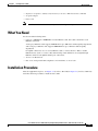
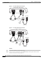
Installation Procedure
After the equipment is in place, see Figure 2-1 (for Cisco ATA 186) or Figure 2-2 (for Cisco ATA 188)
and follow the next procedure to install the Cisco ATA.
Cisco ATA 186 and Cisco ATA 188 Analog Telephone Adaptor Administrator’s Guide for SCCP (version 3.0)
OL-4652-01
2-3
Chapter 2
Installing the Cisco ATA
Installation Procedure
PHONE 1
Cisco ATA 186 Rear Panel Connections
PHONE 2
10BaseT
ACT
72212
Figure 2-1
5V
Power outlet
IP network
Analog telephones
(or fax)
5V power
adaptor
Power cord
PHONE 1
Cisco ATA 188 Rear Panel Connections
PHONE 2
LINK
10/100 PC
10/100 UPLINK LINK
72213
Figure 2-2
5V
Power outlet
IP network
Analog telephones
(or fax)
PC
5V power
adaptor
Power cord
Procedure
Step 1
Place the Cisco ATA near an electrical power outlet.
Step 2
Connect one end of a telephone line cord to the Phone 1 input on the rear panel of the Cisco ATA.
Connect the other end to an analog telephone set.
Cisco ATA 186 and Cisco ATA 188 Analog Telephone Adaptor Administrator’s Guide for SCCP (version 3.0)
2-4
OL-4652-01
Chapter 2
Installing the Cisco ATA
Installation Procedure
If you are connecting a telephone set that was previously connected to an active telephone line, unplug
the telephone line cord from the wall jack and plug it into the Phone 1 input.
Warning
Caution
Note
Step 3
To reduce the risk of fire, use only No. 26 AWG or larger telecommunication line cord.
Do not connect the Phone input ports to a telephone wall jack. To avoid damaging the Cisco ATA or
telephone wiring in the building, do not connect the Cisco ATA to the telecommunications network.
Connect the Phone port to a telephone only, never to a telephone wall jack.
The telephone must be switched to tone setting (not pulse) for the Cisco ATA to operate properly.
(Optional) Connect the telephone line cord of a second telephone to the Phone 2 input port.
If you are connecting only one telephone to the Cisco ATA, you must use the Phone 1 input port.
Step 4
Connect an Ethernet cable to the uplink RJ-45 connector on the Cisco ATA. For the Cisco ATA 186,
this is the 10BASE-T connector; for the Cisco ATA 188, this is the 10/100UPLINK connector.
Use a crossover Ethernet cable to connect the Cisco ATA to another Ethernet device (such as a router or
PC) without using a hub. Otherwise, use a straight-through Ethernet cable.
Step 5
(Cisco ATA 188 only—optional) Connect a straight-through Ethernet cable from your PC to the 10/100
PC RJ-45 connector on the Cisco ATA.
Step 6
Connect the socket end of the power cord to the Cisco-supplied 5V DC power adaptor.
Step 7
Insert the power adaptor cable into the power connector on the Cisco ATA.
Caution
Warning
Step 8
Use only the Cisco-supplied power adaptor.
This product relies on the building’s installation for short-circuit (overcurrent) protection. Ensure that
a fuse or circuit breaker no larger than 120 VAC, 15A U.S. (240VAC, 10A international) is used on the
phase conductors (all current-carrying conductors).
Connect the plug end of the 5V DC power adaptor cord into an electrical power outlet.
When the Cisco ATA is properly connected and powered up, the green activity LED flashes to indicate
network activity. This LED is labeled ACT on the rear panel of the Cisco ATA 186 and is labeled LINK
on the rear panel of the Cisco ATA 188.
Caution
Do not cover or block the air vents on either the top or the bottom surface of the Cisco ATA. Overheating
can cause permanent damage to the unit.
For more information about LEDs and the function button, see the “Hardware Overview” section on
page 1-3.
Cisco ATA 186 and Cisco ATA 188 Analog Telephone Adaptor Administrator’s Guide for SCCP (version 3.0)
OL-4652-01
2-5
Chapter 2
Installing the Cisco ATA
Power-Down Procedure
Power-Down Procedure
Caution
If you need to power down Cisco ATA 186 or Cisco 188 at any time, use the following power-down
procedure to prevent damage to the unit.
Procedure
Step 1
Unplug the RJ45 Ethernet cable
Step 2
Wait for 20 seconds.
Step 3
Unplug the power cable.
Warning
This equipment contains a ring signal generator (ringer), which is a source of hazardous voltage. Do
not touch the RJ-11 (phone) port wires (conductors), the conductors of a cable connected to the RJ-11
port, or the associated circuit-board when the ringer is active. The ringer is activated by an incoming
call.
Cisco ATA 186 and Cisco ATA 188 Analog Telephone Adaptor Administrator’s Guide for SCCP (version 3.0)
2-6
OL-4652-01
C H A P T E R
3
Configuring the Cisco ATA for SCCP
This section describes how to configure the Cisco ATA to operate with the Skinny Client Control
Protocol (SCCP) signaling image and how the Cisco ATA obtains the latest signaling image.
You can configure the Cisco ATA for use with SCCP with any of the following methods:
•
By using the Cisco CallManager TFTP server—This is the Cisco-recommended method for
deploying a large number of Cisco ATAs. This method allows you to set up a default configuration file
for all Cisco ATAs in the network. Additionally, you can set up a configuration file that is unique to a
specific Cisco ATA. When the Cisco ATA powers up or boots up from a reset, it automatically downloads
its configuration file from the Cisco CallManager TFTP server and updates its configuration parameters.
•
By using manual configuration:
– Voice configuration menu—This is the method you must use if the process of establishing IP
connectivity for the Cisco ATA requires changing the default network configuration settings. These
settings are CDP, VLAN, and DHCP. You also can use the voice configuration menu to review all IP
connectivity settings. The voice configuration menu can also be used when Web access is not
available.
– Web-based configuration—This method is convenient if you plan to deploy a small number of
Cisco ATAs in your network. To use this method, the Cisco ATA must first obtain IP connectivity,
either through the use of a DHCP server or by using the voice configuration menu to statically
configure IP addresses.
This section contains the following topics:
•
Default Boot Load Behavior, page 3-2—This section describes the process that the Cisco ATA
follows by default when it boots up. It is very important to understand this process because, if your
network environment is not set up to follow this default behavior, you need to make the applicable
configuration changes. For example, by default, the Cisco ATA attempts to contact a DHCP server
for the necessary IP addresses to achieve network connectivity. However, if your network does not
use a DHCP server, you must manually configure various IP settings as described in this section.
•
Specifying a Preconfigured VLAN ID or Disabling VLAN IP Encapsulation, page 3-3—This
section includes a table of the parameters you can configure for VLAN and CDP settings.
•
Steps Needed to Configure the Cisco ATA, page 3-5—This section provides tables that summarize
the general configuration steps you must follow to configure the Cisco ATA.
•
Configuring the Cisco ATA Using a TFTP Server, page 3-7—This section describes procedures for
configuring the Cisco ATA by using a Cisco CallManager TFTP server, which is the recommended
configuration method for the deployment of a large number of Cisco ATAs.
•
Voice Configuration Menu, page 3-22—This section includes information on how to obtain basic
network connectivity for the Cisco ATA and how to perform a factory reset if necessary.
Cisco ATA 186 and Cisco ATA 188 Analog Telephone Adaptor Administrator’s Guide for SCCP (version 3.0)
OL-4652-01
3-1
Chapter 3
Configuring the Cisco ATA for SCCP
Default Boot Load Behavior
Note
•
Cisco ATA Web Configuration Page, page 3-25—This section shows the Cisco ATA Web
configuration page and contains a procedure for how to configure Cisco ATA parameters using this
interface.
•
Resetting the Cisco ATA Using Cisco CallManager, page 3-26—This section gives the procedure
(via the Cisco CallManager administration web pages) for resetting the Cisco ATA so that your
configuration changes take effect.
•
Upgrading the SCCP Signaling Image, page 3-27—This section provides references to the various
means of upgrading your Cisco ATA signaling image.
The term Cisco ATA is used throughout this manual to refer to both the Cisco ATA 186 and the
Cisco ATA 188, unless differences between the Cisco ATA 186 and Cisco ATA 188 are explicitly
stated.
Default Boot Load Behavior
Before configuring the Cisco ATA, you need to know how the default Cisco ATA boot load process
works. Once you understand this process, you will be able to configure the Cisco ATA by following the
instructions provided in this section and in the sections that follow.
All Cisco ATAs are shipped with a boot load signaling-protocol image. However, because this image is
not a fully functional Cisco ATA image, the Cisco ATA seeks to obtain the image-load information from
the Cisco CallManager and perform a software upgrade. In addition, the Cisco ATA obtains the
necessary SCCP-specific configuration files for Cisco CallManager communication and the Cisco ATA
configuration file during the boot load process.
The following list summarizes the default Cisco ATA behavior during its boot-up process:
1.
Note
2.
Note
3.
The Cisco ATA uses the Cisco Discovery Protocol (CDP) to discover which VLAN to enter. If the
Cisco ATA receives a VLAN ID response from the network switch, the Cisco ATA enters that VLAN
and adds 802.1Q VLAN tags to its IP packets. If the Cisco ATA does not receive a response with a
VLAN ID from the network switch, then the Cisco ATA assumes it is not operating in a VLAN
environment and does not perform VLAN tagging on its packets.
If your network environment is not set up to handle this default behavior, make the necessary
configuration changes by referring to the “Specifying a Preconfigured VLAN ID or Disabling
VLAN IP Encapsulation” section on page 3-3.
The Cisco ATA contacts the DHCP server to request its own IP address.
If your network environment does not contain a DHCP server, you need to statically configure
various IP addresses so that the Cisco ATA can obtain network connectivity. For a list of
parameters that you must configure to obtain network connectivity, see Table 3-7 on page 3-23.
For instructions on how to use the voice configuration menu, which you must use to perform this
configuration, see the “Voice Configuration Menu” section on page 3-22.
Also from the DHCP server, the Cisco ATA requests the IP address of the Cisco CallManager TFTP
server.
Cisco ATA 186 and Cisco ATA 188 Analog Telephone Adaptor Administrator’s Guide for SCCP (version 3.0)
3-2
OL-4652-01
Chapter 3
Configuring the Cisco ATA for SCCP
Specifying a Preconfigured VLAN ID or Disabling VLAN IP Encapsulation
4.
The Cisco ATA contacts the Cisco CallManager TFTP server and downloads the appropriate .xml or
.cnf configuration file that allows the Cisco ATA to communicate with the correct
Cisco CallManager.
5.
The .xml or .cnf file that the Cisco ATA downloads includes information about which signaling
image the Cisco ATA needs to function properly. The Cisco ATA finds that image on the TFTP
server and automatically downloads this image along with the corresponding version of Cisco ATA
release software.
Note
Note
If you are not using a Cisco CallManager TFTP server, you need to manually upgrade the
Cisco ATA to the correct signaling image. For information on this procedure, see the
“Upgrading the Signaling Image Manually” section on page 7-4.
6.
The Cisco ATA looks for a Cisco ATA-specific configuration file (designated by the MAC address
of the Cisco ATA and named ata<macaddress> with a possible extension) on the TFTP server and
downloads this file if it exists. For information about possible configuration file names, see the
“Configuration Files that the cfgfmt Tool Creates” section on page 3-14.
7.
If the Cisco ATA does not find the MAC-address configuration file, it looks for an atadefault.cfg
configuration file and downloads this file if it exists. This file can contain default values for the
Cisco ATA to use.
When the Cisco ATA is downloading its DHCP configuration, the function button on the top panel
blinks.
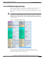
Specifying a Preconfigured VLAN ID or Disabling VLAN IP
Encapsulation
If you want the Cisco ATA to use a preconfigured VLAN ID instead of using the Cisco Discovery
Protocol to locate a VLAN, or if you want to disable VLAN IP encapsulation, refer to Table 3-1 for a
reference to the parameters and bits you may need to configure. Use the voice configuration menu to
configure these parameters. (See the “Voice Configuration Menu” section on page 3-22 for instructions
on using this menu.) Also, refer to Table 3-2 for a matrix that indicates which VLAN-related parameters
and bits to configure depending on your network environment.
Note
Bits are numbered from right to left, starting with bit 0.
Cisco ATA 186 and Cisco ATA 188 Analog Telephone Adaptor Administrator’s Guide for SCCP (version 3.0)
OL-4652-01
3-3
Chapter 3
Configuring the Cisco ATA for SCCP
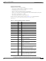
Specifying a Preconfigured VLAN ID or Disabling VLAN IP Encapsulation
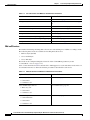
Table 3-1
Parameters and Bits for Preconfiguring a VLAN ID
Parameter and Bits
Reference
OpFlags:
OpFlags, page 5-24
•
Bit 4—Enable the use of user-specified voice VLAN ID.
•
Bit 5—Disable VLAN encapsulation
•
Bit 6—Disable CDP discovery.
VLANSetting:
VLANSetting, page 5-11
•
Bits 0-2—Specify VLAN CoS bit value (802.1P priority) for TCP
packets.
•
Bits 3-5—Specify VLAN CoS bit value (802.1P priority) for
Voice IP packets
•
Bits 18-29—User-specified 802.1Q VLAN ID
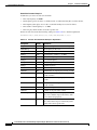
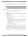
Table 3-2
VLAN-Related Features and Corresponding Configuration Parameters
VLANSetting
OpFlags Bit 4 OpFlags Bit 5 OpFlags Bit 6 Bits 18-29
Feature
Static VLAN
1
0
1
VLAN ID
CDP-acquired
VLAN
0
0
0
N/A
No VLAN
N/A
1
N/A
N/A
No CDP
N/A
N/A
1
N/A
No CDP and no
VLAN
0
1
1
N/A
N/A indicates that the variable is not applicable to the feature and the setting of this variable does not affect the feature.
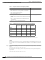
Example
The following procedure shows you how to configure the OpFlags and VLANSetting parameters to allow
the Cisco ATA to use a user-specified VLAN ID. In this example, the voice VLAN ID is 115 (in decimal
format).
Step 1
Set bits 4-6 of the OpFlags parameter to 1, 0, and 1, respectively. This setting translates to the following
bitmap:
xxxx xxxx xxxx xxxx xxxx xxxx x101 xxxx
The remaining bits of the OpFlags parameter, using all default values, make up the following bitmap
representation:
0000 0000 0000 0000 0000 0000 0xxx 0010
Cisco ATA 186 and Cisco ATA 188 Analog Telephone Adaptor Administrator’s Guide for SCCP (version 3.0)
3-4
OL-4652-01
Chapter 3
Configuring the Cisco ATA for SCCP
Steps Needed to Configure the Cisco ATA
Therefore, the resulting value of the OpFlags parameter becomes the following bitmap representation:
0000 0000 0000 0000 0000 0000 0101 0010
In hexadecimal format, this value is 0x00000052.
Step 2
Set bits 18-29 of the VLANSetting parameter to voice VLAN ID 115. This setting translates to the
following bitmap
xx00 0001 1100 11xx xxxx xxxx xxxx xxxx
where 000001110011 is the binary representation of the decimal value 115.
The remaining bits of the VLANSetting parameter, using all default values, make up the following
representation:
00xx xxxx xxxx xx00 0000 0000 0010 1011
Therefore, the resulting value of the VLANSetting parameter becomes the following bitmap
representation:
0000 0001 1100 1100 0000 0000 0010 1011
In hexadecimal format, this value is 0x01cc002b.
Note
If you are using the voice configuration menu to set the parameters, you must convert hexadecimal values
to decimal values. For example, the OpFlags setting of 0x00000052 is equivalent to 82 in decimal
format, and the VLANSetting of 0x01cc002b is equivalent to 30146603 in decimal format.
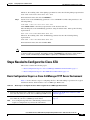
Steps Needed to Configure the Cisco ATA
This section contains the following topics:
•
Basic Configuration Steps in a Cisco CallManager TFTP Server Environment, page 3-5
•
Basic Configuration Steps in a Non-TFTP Server Environment, page 3-6
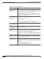
Basic Configuration Steps in a Cisco CallManager TFTP Server Environment
Table 3-3 shows the basic steps for configuring the Cisco ATA and making it operational in a typical
SCCP environment, which includes a Cisco CallManager TFTP server.
Table 3-3
Basic Steps to Configure the Cisco ATA in a Typical Cisco CallManager Environment
Action
Reference
1.
Download the desired Cisco ATA release software zip file from the Setting Up the TFTP Server with Cisco ATA
Cisco web site and store it on the Cisco CallManager TFTP server. Software, page 3-7
2.
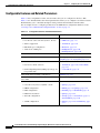
Create a default configuration file that can be used by many
Cisco ATAs in your Cisco CallManager environment.
Note
Creating a Cisco ATA Default Configuration File,
page 3-9
You can skip this step if the Cisco ATA default parameters do not
require re-configuration in your network environment.
Cisco ATA 186 and Cisco ATA 188 Analog Telephone Adaptor Administrator’s Guide for SCCP (version 3.0)
OL-4652-01
3-5
Chapter 3
Configuring the Cisco ATA for SCCP
Steps Needed to Configure the Cisco ATA
Table 3-3
Basic Steps to Configure the Cisco ATA in a Typical Cisco CallManager Environment
Action
Reference
3.
Configure the method with which the Cisco ATA will locate the
Cisco CallManager TFTP server at boot up time.
Configuring the Cisco ATA to Obtain its
Configuration File from the TFTP Server, page
3-18
4.
Add the Cisco ATA to the Cisco CallManager.
Chapter 4, “Adding the Cisco ATA to the
Cisco CallManager”
5.
Power up the Cisco ATA.
6.
Optionally, create a configuration file for a specific Cisco ATA.
7.
If you make configuration changes to the Cisco ATA, you must reset Resetting the Cisco ATA Using
the Cisco ATA by using the Cisco CallManager administration web Cisco CallManager, page 3-26
pages.
Creating a Configuration File for a Specific
Cisco ATA, page 3-11
Basic Configuration Steps in a Non-TFTP Server Environment
Table 3-4 shows the basic steps for configuring the Cisco ATA without using the TFTP server method.
Table 3-4
Basic Steps to Configure the Cisco ATA Without Using the TFTP Server Method
Action
1.
Reference
Download the desired Cisco ATA release software zip file from the Cisco web site:
a. If you are a registered CCO user. go to the following URL:
http://www.cisco.com/cgi-bin/tablebuild.pl/ata186
b. Download the zip file that contains the software for the applicable release and signaling
image you are using. The contents of each file are described next to the file name.
c. Extract the files to the desired location on your PC.
Note
The file that contains the protocol signaling image has an extension of .zup.
2.
Manually upgrade the Cisco ATA to the correct signaling image.
3.
Configure the Cisco ATA by using either one of the manual-configuration methods.
4.
Manually configure the CA0orCM0 parameter to instruct the Cisco ATA about how to
register with Cisco CallManager.
5.
Power up the Cisco ATA.
Upgrading the Signaling
Image Manually, page 7-4
•
Voice Configuration
Menu, page 3-22
•
Cisco ATA Web
Configuration Page,
page 3-25
CA0orCM0 and
CA1orCM1, page 5-12
Cisco ATA 186 and Cisco ATA 188 Analog Telephone Adaptor Administrator’s Guide for SCCP (version 3.0)
3-6
OL-4652-01
Chapter 3
Configuring the Cisco ATA for SCCP
Configuring the Cisco ATA Using a TFTP Server
Configuring the Cisco ATA Using a TFTP Server
The TFTP method of configuration is useful when you have many Cisco ATA because you can use a
TFTP server for remote, batch configuration of Cisco ATAs. A TFTP server can host one unique
configuration file for each Cisco ATA.
This section contains the following topics:
•
Setting Up the TFTP Server with Cisco ATA Software, page 3-7
•
Configurable Features and Related Parameters, page 3-8
•
Creating a Cisco ATA Default Configuration File, page 3-9
•
Creating a Configuration File for a Specific Cisco ATA, page 3-11
•
Configuring the Cisco ATA to Obtain its Configuration File from the TFTP Server, page 3-18
Setting Up the TFTP Server with Cisco ATA Software
This section provides the procedure for the Cisco ATA administrator to obtain the correct Cisco ATA
software and set up the Cisco CallManager TFTP server with this software.
Procedure
Step 1
If you are a registered CCO user. go to the following URL:
http://www.cisco.com/cgi-bin/tablebuild.pl/ata186
Step 2
Download the zip file that contains the software for the applicable release and signaling image you are
using. The contents of each file are described next to the file name. Save the zip file onto a floppy disc.
Note
The file that contains the protocol signaling image has an extension of .zup.
Step 3
Insert the floppy disc into the Cisco CallManager disc drive.
Step 4
From your computer, navigate to Start > Programs > Terminal Services > Client. The Terminal
Services Client screen appears.
Step 5
In the Services field of the Terminal Services Client screen, enter the IP address of the
Cisco CallManager that contains the disc you inserted. Then, click the Connect button. The Login
screen appears.
Step 6
Enter your login information, then click OK. The TFTP Path screen appears.
Step 7
Click on the My Computer icon that is located within the Terminal Services Client screen, then navigate
to the A: drive.
Step 8
From the A: drive, drag the zip file to the TFTP Path screen. This will extract all the files and place them
onto the Cisco CallManager TFTP server.
Cisco ATA 186 and Cisco ATA 188 Analog Telephone Adaptor Administrator’s Guide for SCCP (version 3.0)
OL-4652-01
3-7
Chapter 3
Configuring the Cisco ATA for SCCP
Configuring the Cisco ATA Using a TFTP Server
Configurable Features and Related Parameters
Table 3-5 lists, in alphabetical order, various features that you can configure for the Cisco ATA.
Table 3-5 also includes links to the related parameter that allows you to configure each of these features.
Each link takes you to a detailed description of the parameter that includes its default values.
For an example of how to configure parameters for the TFTP Server configuration method, see the
“Creating a Cisco ATA Default Configuration File” section on page 3-9.
Table 3-5
Configurable Features and Related Parameters
Configurable Features
Related Parameters
Audio Media Features
Audio Media Parameters
•
Low bit-rate codec selection (G.723.1, G.729)
•
LBRCodec, page 5-13
•
Silence suppression
•
AudioMode, page 5-16
•
RTP media port configuration
•
MediaPort, page 5-14
•
Audio level of FXS ports
•
FXSInputLevel, page 5-20,
FXSOutputLevel, page 5-20
Caller ID format
CallerIdMethod, page 5-17
Debug and Diagnostics
NPrintf, page 5-37, TraceFlags, page 5-38,
SyslogIP, page 5-38, SyslogCtrl, page 5-39
Fax Services Features
Fax Services Parameters
•
Fax services mode selection
•
AudioMode, page 5-16, ConnectMode,
page 5-21
•
Named Signalling Event (NSE) payload type for
fax pass-through
•
ConnectMode, page 5-21
Hook-flash detection timing configuration
SigTimer, page 5-23
Mid-call service format—Bellcore, Cisco VG248 or
Cisco ATA
ConnectMode, page 5-21
Network-related Features
Network-related Parameters
•
Cisco Discovery Protocol (CDP)—on/off
•
OpFlags, page 5-24
•
DHCP configuration
•
DHCP, page 5-8, OpFlags, page 5-24
•
DNS configuration
•
DNS1IP, page 5-10, DNS2IP, page 5-11
•
DNS name resolution
•
OpFlags, page 5-24
•
Static IP configuration
•
StaticIp, page 5-9, StaticRoute, page 5-9,
StaticNetMask, page 5-10
•
VLAN configuration
•
OpFlags, page 5-24, VLANSetting, page
5-11
Cisco ATA 186 and Cisco ATA 188 Analog Telephone Adaptor Administrator’s Guide for SCCP (version 3.0)
3-8
OL-4652-01
Chapter 3
Configuring the Cisco ATA for SCCP
Configuring the Cisco ATA Using a TFTP Server
Table 3-5
Configurable Features and Related Parameters (continued)
Configurable Features
Related Parameters
SCCP Terminal-related Features
SCCP Terminal-related Parameters
•
Cisco CallManager 3.0 support
•
ConnectMode, page 5-21
•
Cisco IOS Telephony Solution (ITS) support
•
ConnectMode, page 5-21
•
Domain name in Cisco CallManager environment
•
Domain, page 5-15
•
Static Cisco CallManager configuration
•
CA0orCM0 and CA1orCM1, page 5-12
•
Terminal FXS lines
•
EPID0orSID0 and EPID1orSID1, page
5-13
User Interface and TFTP Features
User Interface and TFTP Parameters
•
User interface password
•
UIPassword, page 5-3
•
TFTP Configuration
•
UseTFTP, page 5-4, TftpURL, page 5-4,
OpFlags, page 5-24
•
TFTP Encryption key
•
EncryptKey, page 5-6, EncryptKeyEx,
page 5-7
•
Web configuration—enable/disable
•
OpFlags, page 5-24
Packet Precedence Features
Packet Precedence Parameters
•
Type of Service (ToS) configuration
•
TOS, page 5-25
•
802.1P Class of Service (Cos) Bit configuration
•
VLANSetting, page 5-11
Polarity settings for FXS ports
Polarity, page 5-19
Tone format: BusyTone, CallWaitTone
DialTone, DialTone2, ReorderTone, RingBackTone
and AlertTone parameters
Tone Configuration Parameters, page 5-26
Tone parameters—Using Network Locale option
versus using Cisco ATA tone parameters
ConnectMode, page 5-21—Bit 0
Version control of Cisco ATA configuration file
CFGID—Version Parameter for Cisco ATA
Configuration File, page 5-40
Creating a Cisco ATA Default Configuration File
The Cisco ATA release-software zip files includes a file called atadefault.cfg, which is a binary file that
contains all the default parameters for the Cisco ATA. However, you likely will need to create your own
atadefault.cfg file to contain the default settings that you want Cisco ATAs in your environment to use.
For information on each configuration parameter, including all default values, see Chapter 5,
“Parameters and Defaults.”
Use the text file called sk_example.txt as a basis for creating your default file. The sk_example.txt file
is included in the software-release zip file and contains all default values. This file is shown without its
annotations in the “Configuration Text File Template” section on page 5-2.
The following procedure illustrates how to create the Cisco ATA default configuration file, convert it to
the required binary format that the Cisco ATA can read, and store it on the TFTP server so that the
Cisco ATA will download it during the boot-up process:
Cisco ATA 186 and Cisco ATA 188 Analog Telephone Adaptor Administrator’s Guide for SCCP (version 3.0)
OL-4652-01
3-9
Chapter 3
Configuring the Cisco ATA for SCCP
Configuring the Cisco ATA Using a TFTP Server
Procedure
Step 1
Make a copy of the sk_example.txt file and rename it atadefault.txt.
Step 2
Make the desired configuration changes by editing the atadefault.txt file, then save the file.
Step 3
Convert the atadefault.txt file to a binary file by running the cfgfmt.exe tool, which is bundled with the
Cisco ATA software.
If you wish to encrypt the binary file for security reasons, see the “Using Encryption With the
cfgfmt Tool” section on page 3-13. If you encrypt the file using the EncryptKeyEx parameter,
the resulting binary file will be called atadefault.cfg.x; if not encrypted with the EncryptKeyEx
parameter the resulting binary file name will be atadefault.cfg.
Note
The syntax of the cfgfmt program follows:
Syntax
cfgfmt [Encryption options] -sccp -tptag.dat input-text-file output-binary-file
– Encryption options are described in the “Using Encryption With the cfgfmt Tool” section on
page 3-13.
– sccp is the protocol you are using, which you must specify so that the cfgfmt tool will include
only the applicable protocol in the converted output binary file.
– The ptag.dat file, provided with the Cisco ATA software version you are running, is used by
cfgfmt.exe to format a text input representation of the parameter/value pairs to its output binary
representation. Be sure this file resides in the same directory from which you are running the
cfgfmt program.
– input-text-file is the input text file representation of the Cisco ATA configuration file.
– output-binary-file is the final output binary file that Cisco ATA uses as the TFTP
configuration file.
Example
cfgfmt -sccp -tptag.dat atadefault.txt atadefault
Step 4
Store the binary configuration file in the TFTP server root directory, overwriting the atadefault.cfg file
that came bundled with the release-software download.
During the boot-up process, the Cisco ATA will download the output file as its configuration file unless
it first finds a Cisco ATA-specific configuration file named for the MAC address of the Cisco ATA. (If
you want to create a MAC-address configuration file for a specific Cisco ATA, see the “Creating a
Configuration File for a Specific Cisco ATA” section on page 3-11.)
Note
If you want to make configuration changes after boot up, repeat the process of creating or editing
the text file containing the desired parameters, then converting the text file to the binary file and
storing the binary file on the TFTP server. For the configuration changes to take effect, reset the
Cisco ATA. (See the “Resetting the Cisco ATA Using Cisco CallManager” section on
page 3-26.)
Cisco ATA 186 and Cisco ATA 188 Analog Telephone Adaptor Administrator’s Guide for SCCP (version 3.0)
3-10
OL-4652-01
Chapter 3
Configuring the Cisco ATA for SCCP
Configuring the Cisco ATA Using a TFTP Server
Creating a Configuration File for a Specific Cisco ATA
Once you have booted up the Cisco ATA, you may decide that you want to create a configuration file
that is specific to one Cisco ATA.
The following procedure illustrates how to create a Cisco ATA-specific configuration file, convert it to
the required binary format that the Cisco ATA can read, and store it on the TFTP server so that the
Cisco ATA will download it as soon as you reset the Cisco ATA.
Procedure
Step 1
Open the atadefault.txt file that you created when you developed your own default file. Find the
parameters whose values you want to change for this specific Cisco ATA. Copy only these parameters
into a new text file. Save the new text file with the following name:
ata<macaddress>.txt
where macaddress is the non-dotted hexadecimal version of the MAC address of the Cisco ATA you are
configuring. This non-dotted hexadecimal MAC address is labeled on the bottom of most Cisco ATAs
next to the word “MAC.” The file name must be exactly 15 characters long. (However, if this filename
is supplied by the DHCP server, the name can be as long as 31 characters and can be any name with
printable ASCII characters.)
If necessary, you can obtain the non-dotted hexadecimal MAC address by using the atapname.exe
command. For information on using the atapname.exe command, see the “Using atapname.exe Tool to
Obtain MAC Address” section on page 3-13. That section includes an example of a dotted decimal MAC
address and its corresponding non-dotted hexadecimal address.
The ata<macaddress>.txt file should contain only those parameters whose values you are
changing from their defaults. Parameter values in the ata<macaddress> configuration file will
overwrite any manually configured values (values configured through the web or voice
configuration menu) when the Cisco ATA powers up or resets.
Note
Example
You might want to change the values of the following parameters, whose default values are shown first:
LBRCodec:3
AudioMode:0x00350035
You could change the values as follows:
LBRCodec:0
AudioMode:0x00350034
Step 2
Save your changes.
Cisco ATA 186 and Cisco ATA 188 Analog Telephone Adaptor Administrator’s Guide for SCCP (version 3.0)
OL-4652-01
3-11
Chapter 3
Configuring the Cisco ATA for SCCP
Configuring the Cisco ATA Using a TFTP Server
Step 3
Run the cfgfmt.exe tool, which is bundled with the Cisco ATA software, on the ata<macaddress>.txt
text file to generate the binary configuration file. If you wish to encrypt the binary file, see the “Using
Encryption With the cfgfmt Tool” section on page 3-13.
The syntax of the cfgfmt program follows:
Syntax
cfgfmt [Encryption options] -sccp -tptag.dat input-text-file output-binary-file
– Encryption options are described in the “Using Encryption With the cfgfmt Tool” section on
page 3-13.
– sccp is the protocol you are using, which you must specify so that the cfgfmt tool will include
only the applicable protocol in the converted output binary file.
– The ptag.dat file, provided with the Cisco ATA software version you are running, is used by
cfgfmt.exe to format a text input representation of the parameter/value pairs to its output binary
representation. Be sure this file resides in the same directory from which you are running the
cfgfmt program.
– input-text-file is the input text file representation of the Cisco ATA configuration file.
– output-binary-file is the final output binary file that Cisco ATA uses as the TFTP
configuration file.
Example
cfgfmt -sccp -tptag.dat ata0a141e28323c.txt ata0a141e28323c
This example is based on a Cisco ATA MAC address of 10.20.30.40.50.60, which converts to the
two-digit, lower-case hexadecimal representation of each integer as 0a141e28323c.
Step 4
Store all binary configuration file(s) in the TFTP server root directory. For information about possible
configuration file names, see the “Configuration Files that the cfgfmt Tool Creates” section on
page 3-14.
Step 5
Reset the Cisco ATA using the Cisco CallManager. (See the “Resetting the Cisco ATA Using Cisco
CallManager” section on page 3-23.)
After being reset, the Cisco ATA will download this ata<macaddress> binary configuration file as its
unique configuration file. This file takes precedence over the atadefault.cfg file. If the Cisco ATA finds
an ata<macaddress> file on the TFTP server, the Cisco ATA does not look for the atadefault.cfg file.
Cisco ATA 186 and Cisco ATA 188 Analog Telephone Adaptor Administrator’s Guide for SCCP (version 3.0)
3-12
OL-4652-01
Chapter 3
Configuring the Cisco ATA for SCCP
Configuring the Cisco ATA Using a TFTP Server
Using atapname.exe Tool to Obtain MAC Address
This bundled tool is useful for converting the dotted decimal version of the Cisco ATA MAC address
(available on the Cisco ATA Web configuration page or from the voice configuration menu code 24#)
to its default Cisco ATA profile name. This name has the following format:
ataxxxxxxxxxxxx
where each xx is the two-digit, lower-case hexadecimal representation of each integer in the dotted,
decimal version of the Cisco ATA MAC address. This is the name you use for the unique Cisco ATA
binary configuration file.
The following command and output show an example of this command.
Command Example
atapname.exe 10.20.30.40.50.60
Command Output
ata0a141e28323c
Note
The same functionality is available from the voice configuration menu (voice menu code 84#), which
will announce the Cisco ATA profile name.
Using Encryption With the cfgfmt Tool
The EncryptKey or EncryptKeyEx parameter can be used to encrypt binary files that are transferred over
TFTP. You can change encryption keys for each Cisco ATA so that only one specific Cisco ATA can
decode the information.
Cisco strongly recommends using the EncryptKeyEx parameter for encryption because this parameter
provides a stronger encryption than the EncryptKey parameter that was used in Cisco ATA software
releases prior to release 2.16.
You must use version 2.3 of the cfgfmt configuration-file generation tool to use the new EncryptKeyEx
parameter. This tools comes bundled with Cisco ATA software version 3.0. To verify that you have
version 2.3 of the cfgfmt tool type the following command:
cfgfmt
The version number of the cfgfmt tool will be returned.
You can configure the EncryptKeyEx parameter by using the Cisco ATA Web configuration page or by
using the TFTP configuration method. (For more information, see the “EncryptKeyEx” section on
page 5-7.)
You can configure the EncryptKey parameter by using the Cisco ATA Web configuration page, the
voice configuration menu, or by using the TFTP configuration method. (For more information, see the
“EncryptKey” section on page 5-6.)
By default, the Cisco ATA-specific ata<macaddress> configuration file(s) are not encrypted. If
encryption is required, however, you must manually configure the EncryptKeyEx or EncryptKey
parameter before you boot up the Cisco ATA so that the TFTP method is secure. The Cisco ATA uses
the RC4 cipher algorithm for encryption.
Cisco ATA 186 and Cisco ATA 188 Analog Telephone Adaptor Administrator’s Guide for SCCP (version 3.0)
OL-4652-01
3-13
Chapter 3
Configuring the Cisco ATA for SCCP
Configuring the Cisco ATA Using a TFTP Server
Note
Because the factory-fresh ATA cannot accept encrypted configuration files, the first unencrypted file, if
intercepted, can easily be read. (You would still have to know the data structure format in order to
decode the binary information from the unencrypted file.) Therefore, the new encryption key in the
unencrypted file can be compromised.
Note
For security reasons, Cisco recommends that you set the UIPassword parameter (if desired) in the
configuration file and not by using one of the manual configuration methods.
This section contains the following topics:
•
Configuration Files that the cfgfmt Tool Creates, page 3-14
•
cfgfmt Tool Syntax and Examples, page 3-15
Configuration Files that the cfgfmt Tool Creates
The number of output binary configuration files that the Cisco ATA produces is dependent on two
factors:
•
Which encryption key parameter is used—EncryptKey or EncryptKeyEx
•
The total size of the binary output
Table 3-6 shows the names of the binary files that can be generated. One, two or four files can be
generated.
Note
<macaddress> in Table 3-6 is the MAC address of the Cisco ATA.
Note
If you are creating an atadefault configuration file, the generated binary file name will be
atadefault.cfg.x if you encrypt the text file with the EncryptKeyEx parameter; the binary file name will
be atadefault.cfg if you do not use the EncryptKeyEx parameter to encrypt the text file.
Table 3-6
Configuration Files that the Cisco ATA May Generate
Total Binary Output Size Less
Than or Equal to 2,000 Bytes
Total Binary Output Size
Greater Than 2,000 Bytes
ata<macaddress>
ata<macaddress>
Value of
EncryptKeyEx
Parameter
0
ata<macaddress>.ex
Non-zero
ata<macaddress>
ata<macaddress>
ata<macaddress>.x
ata<macaddress>.ex
ata<macaddress>.x
ata<macaddress>.xex
Cisco ATA 186 and Cisco ATA 188 Analog Telephone Adaptor Administrator’s Guide for SCCP (version 3.0)
3-14
OL-4652-01
Chapter 3
Configuring the Cisco ATA for SCCP
Configuring the Cisco ATA Using a TFTP Server
Note
Place all generated binary configuration files onto the TFTP server.
cfgfmt Tool Syntax and Examples
The syntax of the cfgfmt tool follows:
Syntax
cfgfmt [options] input output
Syntax Definitions—Options
•
-eRc4Passwd—This option directs the Cisco ATA to use Rc4Passwd as the key (up to eight
hexadecimal characters) to encrypt or decrypt the input text file. However, if the Cisco ATA
EncryptKey parameter in the input text file is not 0, then the value of that parameter is used to
encrypt the output binary file, and Rc4Passwd is ignored. The -e portion of this option means that
the Cisco ATA will use the weaker encryption method.
•
-E—This option directs the Cisco ATA to not use the value of the EncryptKey parameter, as set in
the input text file, to encrypt the output binary configuration file.
•
-xRc4Passwd—This option directs the Cisco ATA to use Rc4Passwd, which must be a hexadecimal
string of as many as 64 characters, as the key to encrypt or decrypt the input text file. However, if
the Cisco ATA EncryptKeyEx parameter in the input text file is not 0, then the value of that
parameter is used to encrypt the output binary file, and Rc4Passwd is ignored. The -x portion of this
option means that the Cisco ATA will use the stronger encryption method.
•
-X—This option directs the Cisco ATA to not use the value of the EncryptKeyEx parameter, as set
in the input text file, to encrypt the output binary configuration file.
•
-tPtag.dat—This file, provided with the Cisco ATA software version you are running, is used by the
cfgfmt tool to format a text input representation of the parameter/value pairs to its output binary
representation. Be sure this file resides in the same directory from which you are running the cfgfmt
program.
•
-sip—Specify this tag if you are using the SIP protocol so that the cfgfmt tool will include only the
SIP protocol parameters in the converted output binary file.
•
-h323—Specify this tag if you are using the H.323 protocol so that the cfgfmt tool will include only
the H.323 protocol parameters in the converted output binary file.
•
-mgcp—Specify this tag if you are using the MGCP protocol so that the cfgfmt tool will include
only the MGCP protocol parameters in the converted output binary file.
•
-sccp—Specify this tag if you are using the SCCP protocol so that the cfgfmt tool will include only
the SCCP protocol parameters in the converted output binary file.
•
-g—This tag omits sensitive parameters in an ata<macaddress> file that was created with a version
of the cfgfmt tool prior to version 2.3.
Some parameters, specified in the ptag.dat file used by the cfgfmt tool, are marked as sensitive
information (these parameters could include UIPassword, UID, PWD0). These parameters are not
included in the output binary file if the -g switch is specified in the cfgfmt syntax.
Syntax Definitions—Required Parameters
•
Input—This is the input text file representation of the Cisco ATA configuration file.
•
Output—This is the final output binary file that Cisco ATA uses as the TFTP configuration file.
Cisco ATA 186 and Cisco ATA 188 Analog Telephone Adaptor Administrator’s Guide for SCCP (version 3.0)
OL-4652-01
3-15
Chapter 3
Configuring the Cisco ATA for SCCP
Configuring the Cisco ATA Using a TFTP Server
Syntax examples
The cfgfmt.exe syntax affects how the EncryptKeyEx or EncryptKey parameters are used, as shown in
the following examples. In these examples, input-text-file is the ata<macaddress>.txt file that you will
convert to binary to create the ata<macaddress> configuration file(s) for the Cisco ATA;
output-binary-file is that binary ata<macaddress> file, and Secret is the encryption key.
•
cfgfmt -sccp -tptag.dat input-text-file output-binary-file
If input-text-file sets the Cisco ATA EncryptKey parameter to 0, then output-binary-file is not
encrypted. If the input-text-file sets EncryptKey to a non-zero value, then output-binary-file is
encrypted with that value.
•
cfgfmt -X -sccp -tptag.dat input-text-file output-binary-file
This is an example of how you might perform encryption on a first-time Cisco ATA.
The -X (uppercase) option means that any value specified for the Cisco ATA EncryptKeyEx
parameter in input-text-file is ignored. However, because Secret is not specified in this example,
output-binary-file is not encrypted. Nevertheless, the EncryptKeyEx parameter and its value, if
specified in input-file-text, will be included in output-binary-file for possible encryption at a later
time. The next time the Cisco ATA fetches the configuration file from the TFTP server, the file will
be encrypted with Secret.
•
cfgfmt -X -xSecret -sccp -tptag.dat input-text-file
output-binary-file
This is an example of changing the encryption key from one key to another key.
The -X (uppercase) option means that any value specified for the Cisco ATA EncryptKeyEx
parameter in input-text-file is ignored and the output-binary-file is encrypted with the Secret key.
However, the EncryptKeyEx parameter and its value, if specified in input-text-file, will be included
in output-binary-file.
Examples of Upgrading to Stronger Encryption Key
This section contains two examples of how you would upgrade your Cisco ATA configuration to use the
stronger encyrption method if the current Cisco ATA firmware version was a version earlier than version
2.16.2. Versions earlier than 2.16.2 do not support the stronger EncryptKeyEx parameter.
Example 1
In this example, the Cisco ATA has not yet been deployed, but its firmware version is earlier than 2.16.2.
Therefore, the Cisco ATA will upgrade to to firmware version 3.0 to use the EncryptKeyEx parameter
as its encryption key.
The Cisco ATA in this example has a MAC address of 102030405060.
Perform the following steps:
Procedure
Step 1
Create a file called ata102030405060.txt by using the applicable example.txt file provided with the
Cisco ATA software. (For example, for SCCP, the example.txt file is called sk_example.txt.)
Step 2
Modify the ata102030405060.txt file with desired parameter values. The value of the EncryptKey
parameter should be 0.
Cisco ATA 186 and Cisco ATA 188 Analog Telephone Adaptor Administrator’s Guide for SCCP (version 3.0)
3-16
OL-4652-01
Chapter 3
Configuring the Cisco ATA for SCCP
Configuring the Cisco ATA Using a TFTP Server
Step 3
Set the value of the EncryptKeyEx parameter to the chosen encryption key with which you want the
output binary file to be encrypted. In the EncryptKeyEx parameter specified in the configuration file,
you can also restrict the EncryptKeyEx value to apply only to the Cisco ATA with a particular MAC
address. For example, if the chosen key value is 231e2a7f10bd7fe, you can specify EncryptKeyEx as:
EncryptKeyEx:231e2a7f10bd7fe/102030405060
This means that only the Cisco ATA with the MAC address 102030405060 will be allowed to apply this
EncryptKeyEx value to its internal configuration.
Step 4
Update the upgradecode parameter to instruct the Cisco ATA to upgrade to firmware version 3.0 by
means of TFTP configuration. The upgradecode parameter is described in Chapter 7, “Upgrading the
Cisco ATA Signaling Image.”
Step 5
Run the cfgfmt tool as follows:
cfgfmt -g ata102030405060.txt ata102030405060
This will generate the following two binary configuration files:
•
ata102030405060
•
ata102030405060.x
ata102030405060 is unencrypted.
ata102030405060.x is encrypted with EncryptKeyEx value.
Step 6
Place these two files on the TFTP server that the Cisco ATA will contact for its configuration files.
When the Cisco ATA powers up, it will obtain its IP address from the DHCP server. If the DHCP server
specifies the TFTP server address, the Cisco ATA will contact the TFTP server obtained from DHCP
because the Cisco ATA is not preconfigured with a TFTP server address. The boot process is as follows:
a. The Cisco ATA downloads the configuration file ata102030405060 from the TFTP server.
b. The Cisco ATA applies parameter values in the file ata102030405060 to its internal
configuration while ignoring the EncryptKeyEx parameter (because the older version of the
Cisco ATA does not yet recognize the EncryptKeyEx parameter).
c. The Cisco ATA upgrades to the 3.0 firmware load.
d. The Cisco ATA reboots.
e. The Cisco ATA again downloads the configuration file ata102030405060.
f. The Cisco ATA applies the value of the EncryptKeyEx parameter to its internal configuration.
g. The Cisco ATA reboots.
h. The Cisco ATA EncryptKeyEx value is in effect, so from this point forward the Cisco ATA will
download the ata102030405060.x file at each reboot and each time the value configured in the
CfgInterval parameter expires.
Note
Although EncryptKeyEx is encrypted in the ata<macaddress> file, and the ata<macaddress> file
does not contain other sensitive information, Cisco recommends that for absolute security you
pre-configure the Cisco ATA as described in this example for a private network. Alternatively, you
should remove ata<macaddress> once EncryptKeyEx takes effect.
Cisco ATA 186 and Cisco ATA 188 Analog Telephone Adaptor Administrator’s Guide for SCCP (version 3.0)
OL-4652-01
3-17
Chapter 3
Configuring the Cisco ATA for SCCP
Configuring the Cisco ATA Using a TFTP Server
Example 2
In this example, a new Cisco ATA has already been deployed (with the EncryptKey value set) with a
firmware version earlier than 2.16.2. The Cisco ATA needs to be upgraded to version 2.16.2 firmware
or greater to use EncryptKeyEx parameter to encrypt its configuration file.
In this scenario, you would follow the same procedure as in Example 1, except that you would need to
set the EncryptKey value to the previously configured EncryptKey value. The difference is that the
ata<macaddress> file is now encrypted with EncryptKey because the Cisco ATA expects the
ata<macaddress> file to be encrypted with EncryptKey. The Cisco ATA can then begin using the
ata<macaddress>.x file that is encrypted with the EncryptKeyEx parameter.
Configuring the Cisco ATA to Obtain its Configuration File from the TFTP Server
This section describes three methods from which to choose how the Cisco ATA contacts the TFTP server
to obtain its configuration file:
•
Using a DHCP Server, page 3-18
– The Cisco ATA contacts the DHCP server, which provides the IP address of the TFTP server
– The Cisco ATA uses the DHCP server but the DHCP server does not know about TFTP server
•
Note
Without Using a DHCP Server, page 3-21
In the rare instance where no TFTP server is used, you must manually configure the CA0orCM0
parameter to instruct the Cisco ATA about how to register with Cisco CallManager. For this scenario,
see the “CA0orCM0 and CA1orCM1” section on page 5-12.
Using a DHCP Server
When using a DHCP server, configuration settings vary depending on whether or not the DHCP server
is under the control of the Cisco ATA system administrator or the service provider. The simplest
configuration is when the DHCP server is under the control of the Cisco ATA administrator, in which
case the DHCP server provides the IP address of the TFTP server. Depending on who controls the DHCP
server, follow the applicable configuration procedure:
•
Procedure if DHCP Server is Under Control of Cisco ATA Administrator, page 3-19
•
Procedure if DHCP Server is not Under Control of Cisco ATA Administrator, page 3-20
This section also includes the topic:
•
Note
Other DHCP Options You Can Set, page 3-20
If no DHCP server is found and the Cisco ATA is programmed to find one, the function button
continues to blink.
Cisco ATA 186 and Cisco ATA 188 Analog Telephone Adaptor Administrator’s Guide for SCCP (version 3.0)
3-18
OL-4652-01
Chapter 3
Configuring the Cisco ATA for SCCP
Configuring the Cisco ATA Using a TFTP Server
Procedure if DHCP Server is Under Control of Cisco ATA Administrator
Procedure
Step 1
On the DHCP server, set one of the following three options:
•
DHCP option 150 (TFTP server IP address and, if applicable, IP address of alternate TFTP server).
•
DHCP field siaddr (TFTP server IP address). This field can be used by systems such as
Cisco Integrated Communications Services (ICS).
•
Standard DHCP option 66 (TFTP server name and, if applicable, name of alternate TFTP server).
If you use DHCP option 150, the Cisco ATA will ignore the DHCP siaddr field and DHCP option 66. If
DHCP option 150 is not used, the Cisco ATA next looks for the DHCP field siaddr. If neither DHCP
option 150 nor the siaddr field are available, the Cisco ATA looks for DHCP option 66. If you use DHCP
option 66 or the DHCP siaddr field, you must turn off DHCP option 150 or set its value to 0.
Note
Step 2
You can turn off the DHCP option 150 request by using the Cisco ATA OpFlags parameter (see
the “OpFlags” section on page 5-24).
Make sure to use default values for the following Cisco ATA parameters:
•
TftpUrl=0
•
AlttftpURL=0
•
UseTftp=1
•
DHCP=1
•
CA0orCM0=0
This completes the parameter settings and DHCP options you need to configure for this procedure. The
Cisco ATA will contact the DHCP server for the IP address of the TFTP server that contains the
Cisco ATA configuration file.
Note
If you are configuring an alternate TFTP server, you can choose to configure its IP address or URL with
the AlttftpURL parameter (see the “AlttftpURL” section on page 5-5) instead of with DHCP option 150.
In this situation, the AlttftpURL will not be 0, as indicated in Step 2 of this procedure.
Cisco ATA 186 and Cisco ATA 188 Analog Telephone Adaptor Administrator’s Guide for SCCP (version 3.0)
OL-4652-01
3-19
Chapter 3
Configuring the Cisco ATA for SCCP
Configuring the Cisco ATA Using a TFTP Server
Procedure if DHCP Server is not Under Control of Cisco ATA Administrator
This is the procedure to use if the DHCP server is not under the control of the Cisco ATA administrator,
which means that the URL of the TFTP server must be manually configured.
Procedure
Step 1
Using the voice configuration menu, set the parameter TftpURL to the IP address or URL of the TFTP
server. For more information on setting the TftpURL parameter, see the “TftpURL” section on page 5-4.
For information about using the Cisco ATA voice configuration menu, see the “Voice Configuration
Menu” section on page 3-22.
Note
If you are not using a DHCP server to provide the TFTP server location, you must manually
configure the TftfURL. You can do this by using the voice configuration menu without first
obtaining network connectivity for the Cisco ATA. If you want to configure this value using the
Web configuration page, you first must obtain network connectivity by using the voice
configuration menu to statically configure IP address information (see the “Voice Configuration
Menu” section on page 3-22).
Step 2
If you have an alternate TFTP server that you also want to configure with the Cisco ATA configuration
process, set the AlttftpURL parameter to the IP address or URL of the alternate TFTP server. For more
information about the AlttftpURL parameter, see the “AlttftpURL” section on page 5-5.
Step 3
Use the default value of 1 for the Cisco ATA parameter DHCP.
Step 4
Use the default value of 1 for the Cisco ATA parameter UseTftp.
Step 5
Use the default value of 0 for the Cisco ATA parameter CA0orCM0.
This completes the parameter settings you need to configure for this procedure. The Cisco ATA will
contact the manually configured TFTP server that contains the Cisco ATA configuration file.
Other DHCP Options You Can Set
The following parameters can also be configured with DHCP:
Note
•
Boot file name of DHCP header—The ata<macaddress> binary Cisco ATA configuration file,
which can have a maximum of 31 characters and can be any name with printable ASCII characters
•
Client PC address
•
DHCP option 1—Client Subnet Mask
•
DHCP option 3—Routers on the client’s subnet
•
DHCP option 6—One or two Domain Name servers
DHCP options 43 and 60 are set by the Cisco ATA. Option 43 specifies the protocol and option 60
identifies the vendor class of the Cisco ATA box.
Cisco ATA 186 and Cisco ATA 188 Analog Telephone Adaptor Administrator’s Guide for SCCP (version 3.0)
3-20
OL-4652-01
Chapter 3
Configuring the Cisco ATA for SCCP
Configuring the Cisco ATA Using a TFTP Server
Without Using a DHCP Server
Use the following procedure if you are not using a DHCP server in your environment but are still using
a TFTP server to obtain the Cisco ATA configuration file:
Procedure
Step 1
Set the DHCP parameter to 0.
Step 2
Set the UseTftp parameter to 1.
Step 3
Set the Cisco ATA parameter TftpURL to the IP address or URL of the TFTP server. For more
information on setting the TftpURL parameter, see the “TftpURL” section on page 5-4.
Note
If you are not using a DHCP server to provide the TFTP server location, you must manually enter
the TftpURL using either the voice configuration menu or the web configuration page.
Step 4
If applicable, set the Cisco ATA parameter AlttftpURL to the IP address or URL of the alternate TFTP
server. For more information about the AlttftpURL parameter, see the “AlttftpURL” section on
page 5-5.
Step 5
If you have not already done so, statically configure the following parameters using the voice
configuration menu (see the “Voice Configuration Menu” section on page 3-22). These are the
parameters you need to configure for the Cisco ATA to obtain network connectivity:
•
StaticIP
•
StaticRoute
•
StaticNetMask
Other parameters that are normally supplied by DHCP may be provided statically by configuring their
values. These parameters are:
•
DNS1IP
•
DNS2IP
•
Domain
This completes the parameter settings you need to configure in order for the Cisco ATA to contact the
TFTP server (without using DHCP) that will contain the configuration file for the Cisco ATA.
Cisco ATA 186 and Cisco ATA 188 Analog Telephone Adaptor Administrator’s Guide for SCCP (version 3.0)
OL-4652-01
3-21
Chapter 3
Configuring the Cisco ATA for SCCP
Voice Configuration Menu
Voice Configuration Menu
The main reasons to use the voice configuration menu are to establish IP connectivity for the Cisco ATA
if a DHCP server is not being used in your network environment, and to reset the Cisco ATA to its
factory values if necessary. You can also use the voice configuration menu if you need to configure a
small number of parameters or if the web interface and TFTP configuration are not available.
Note
Do not use the voice configuration menu to attempt to change any values that you configured by means
of the TFTP configuration file method. Whenever the Cisco ATA resets, it downloads its
ata<macaddress> configuration file or atadefault.cfg default configuration file from the TFTP server,
and the values in either of these files will overwrite the values of any corresponding parameters
configured with the voice configuration menu.
See Chapter 5, “Parameters and Defaults,” for a complete list of parameters and their definitions. Also
see Table 3-5 on page 3-8 for an alphabetical listing of configurable features and references to their
corresponding parameters.
This section contains the following topics:
•
Using the Voice Configuration Menu, page 3-22
•
Entering Alphanumeric Values, page 3-24
•
Resetting the Cisco ATA to Factory Default Values, page 3-24
Using the Voice Configuration Menu
To manually configure the Cisco ATA by using the voice configuration menu and the telephone keypad,
perform the following steps:
Procedure
Step 1
Connect an analog touch-tone phone to the port labeled Phone 1 on the back of the Cisco ATA.
Step 2
Lift the handset and press the function button located on the top of the Cisco ATA. You should receive
the initial voice configuration menu voice prompt.
Step 3
Using the telephone keypad, enter the voice menu code for the parameter that you want to configure or
the command that you want to execute, then press #. For a list of voice menu codes, see Appendix B,
“Voice Menu Codes.”
Table 3-7 lists the menu options that you need to configure basic IP connectivity for the Cisco ATA,
after which you can use the Cisco ATA web configuration page to configure additional parameters.
Note
If you are using the voice configuration menu to statically configure the Cisco ATA IP address,
you must disable DHCP by setting its value to 0.
Cisco ATA 186 and Cisco ATA 188 Analog Telephone Adaptor Administrator’s Guide for SCCP (version 3.0)
3-22
OL-4652-01
Chapter 3
Configuring the Cisco ATA for SCCP
Voice Configuration Menu
Table 3-7
Step 4
Parameters that Provide Basic IP Connectivity for the Cisco ATA
Voice Menu
Number
Features
1
StaticIP—IP address of the Cisco ATA.
2
StaticRoute—Default gateway for the Cisco ATA to use.
10
StaticNetMask—Subnet mask of the Cisco ATA.
20
DHCP—Set value to 0 to disable the use of a DHCP server; set value to 1 to enable
DHCP.
21
Review the IP address of the Cisco ATA.
22
Review the default router for the Cisco ATA to use.
23
Review subnet mask of the Cisco ATA.
Follow the voice prompts and enter the appropriate values, then press the # key.
Note
Use the * key to indicate a delimiter (dot). For example, to enter an IP address of 192.168.3.1,
you would enter 192*168*3*1 on your telephone keypad.
Note
When entering values for a field that contains a hexadecimal value, you must convert the
hexadecimal value to a decimal value in order to enter it into the voice configuration menu
system. For example, to enter the hexadecimal value 0x6A, you would enter the number 106 on
the telephone keypad.
The voice configuration menu repeats the value you entered, then prompts you to press one of the
following keys:
•
1=Change your entered value
•
2=Review your entered value
•
3=Save your entered value
•
4=Review the current saved value
Step 5
Cisco strongly recommends that you set a password. Use the voice menu code 7387277 (SETPASS) to
configure a password through the voice configuration menu, after which you are prompted for the
password whenever you attempt to change a parameter value.
Step 6
After completing the configuration through the voice configuration menu, press the # key to exit.
Step 7
Hang up the telephone. The Cisco ATA configuration refreshes. The function button fast-blinks when
the refresh is completed.
Cisco ATA 186 and Cisco ATA 188 Analog Telephone Adaptor Administrator’s Guide for SCCP (version 3.0)
OL-4652-01
3-23
Chapter 3
Configuring the Cisco ATA for SCCP
Voice Configuration Menu
Entering Alphanumeric Values
Some voice configuration menu options require you to enter alphanumeric characters. Alphanumeric
entry differs from numeric entry because you must press # after each character selected.
If you need to enter an alphanumeric value, the voice prompt tells you to enter an alphanumeric value;
otherwise, enter a numeric value (0 to 9).
Table 3-8 lists the keys on a telephone keypad and their respective alphanumeric characters.
Using Table 3-8 as a guide, enter the appropriate number key on the telephone keypad as many times as
needed to select the number, letter, or symbol required. For example, to enter 58sQ, you would enter:
5 # 8 # 7 7 7 7 7 # 7 7 7 7 7 7 7 # #
Table 3-8
Alphanumeric Characters
Key
Alphanumeric Characters
1
1 ./_\ @*space return +-!,?|~^#=$”‘’%<>[] :;{}()&
2
2abcABC
3
3defDEF
4
4ghiGHI
5
5jklJKL
6
6mnoMNO
7
7pqrsPQRS
8
8tuvTUV
9
9wxyzWXYZ
0
0
Resetting the Cisco ATA to Factory Default Values
It is possible that you may, under some circumstances, want to reset the Cisco ATA to its factory default
values. For example, this is the only way to recover a forgotten password without contacting your Cisco
representative.
To perform a factory reset, you must use the voice configuration menu and follow these steps:
Procedure
Step 1
Press the function button on the Cisco ATA.
Step 2
Press the digits 322873738 (FACTRESET) then press # on the telephone keypad.
Step 3
Press * on your telephone keypad to confirm that you want to reset the Cisco ATA, then hang up the phone.
Cisco ATA 186 and Cisco ATA 188 Analog Telephone Adaptor Administrator’s Guide for SCCP (version 3.0)
3-24
OL-4652-01
Chapter 3
Configuring the Cisco ATA for SCCP
Cisco ATA Web Configuration Page
Cisco ATA Web Configuration Page
You can use the Cisco ATA web configuration page in a non-TFTP configuration environment, or in a
TFTP configuration environment as a read-only record of individual customer parameters.
Figure 3-1 shows an example of the Cisco ATA web configuration page, which displays all configurable
parameters.
Note
Do not use the web configuration page to attempt to change any values that you configured by means of
the TFTP configuration file method. Whenever the Cisco ATA resets, it downloads its ata<macaddress>
configuration file or atadefault.cfg default configuration file from the TFTP server, and the values in
either of these files will overwrite the values of any corresponding parameters configured with the Web
configuration method.
Figure 3-1
Cisco ATA Web Configuration Page
You can access the web configuration page from any graphics-capable browser, such as
Microsoft Internet Explorer or Netscape. This provides easy initial access to the Cisco ATA
configuration within the administrator’s private network.
Cisco ATA 186 and Cisco ATA 188 Analog Telephone Adaptor Administrator’s Guide for SCCP (version 3.0)
OL-4652-01
3-25
Chapter 3
Configuring the Cisco ATA for SCCP
Resetting the Cisco ATA Using Cisco CallManager
Follow these steps to set parameters using the web configuration page:
Procedure
Step 1
Make sure that your PC and the Cisco ATA are already networked and visible to each another.
Step 2
Open your web browser.
Step 3
Enter the URL for your configuration page. The default URL for the web server is:
http://IP Address/dev
For example, the configuration page for a Cisco ATA with the IP address 192.168.3.225 is:
http://192.168.3.225/dev
Step 4
Select the values for the items that you want to configure. See Chapter 5, “Parameters and Defaults,” for
a complete list of parameters and their definitions. Also see Table 3-5 on page 3-8 for an alphabetical
listing of configurable features and references to their corresponding parameters.
Note
Cisco strongly recommends that you set a password. Use the UIPassword parameter to configure a
password, after which you are prompted for the password whenever you attempt to change a parameter
value. Configuration parameters cannot be accessed through the voice configuration menu if the
password contains one or more letters and can be changed only by using the web interface or the TFTP
configuration method.
Step 5
Click apply to save your changes.
The Cisco ATA automatically refreshes its configuration.
Step 6
Close your web browser.
Resetting the Cisco ATA Using Cisco CallManager
Whenever you make configuration changes to the Cisco ATA, you must reset the Cisco ATA using the
Cisco CallManager for these configuration changes to take effect. To reset the Cisco ATA, use the
following procedure:
Procedure
Step 1
Go to the main Cisco CallManager Administration screen.
Step 2
Using voice configuration menu code 21, review the Cisco ATA IP address.
Step 3
From the Device pull-down menu, select Phone. The Find and List Phones screen appears.
Step 4
In the area next to the Find button, enter a portion or all of the Cisco ATA MAC address, then press Find.
The Find and List Phones screen reappears, and now contains the Cisco ATAs that match the find criteria
you entered in the previous screen.
Step 5
Click the icon of the Cisco ATA that you would like to reset. The Phone Configuration screen appears.
Cisco ATA 186 and Cisco ATA 188 Analog Telephone Adaptor Administrator’s Guide for SCCP (version 3.0)
3-26
OL-4652-01
Chapter 3
Configuring the Cisco ATA for SCCP
Upgrading the SCCP Signaling Image
Step 6
Click the Reset Phone button on the Phone Configuration screen. The Reset Device pop-up window
appears.
Step 7
Click Reset.
Step 8
A confirmation box appears. Click OK.
Upgrading the SCCP Signaling Image
For instructions on how to upgrade the Cisco ATA to the most recent SCCP signaling image, refer to the
following list:
•
To use the recommended Cisco CallManager TFTP method of upgrading any or all Cisco ATAs at
one time, see the “Upgrading the Signaling Image Via Cisco CallManager” section on page 7-2.
•
In the rare instance that you are not using the Cisco CallManager TFTP to configure the Cisco ATA
and to obtain software upgrades, you must manually upgrade to the latest signaling image
immediately after the Cisco ATA boots up. In this case, see the “Upgrading the Signaling Image
Manually” section on page 7-4.
Cisco ATA 186 and Cisco ATA 188 Analog Telephone Adaptor Administrator’s Guide for SCCP (version 3.0)
OL-4652-01
3-27
Chapter 3
Configuring the Cisco ATA for SCCP
Upgrading the SCCP Signaling Image
Cisco ATA 186 and Cisco ATA 188 Analog Telephone Adaptor Administrator’s Guide for SCCP (version 3.0)
3-28
OL-4652-01
C H A P T E R
4
Adding the Cisco ATA to the Cisco CallManager
Once you have configured the Cisco ATA, converted the configuration file into a binary file and stored
the file on the Cisco CallManager TFTP server, you must register the Cisco ATA with
Cisco CallManager.
This section contains important information about which device type to use when you register the
Cisco ATA as well as how to choose which registration method is best based on your Cisco CallManager
environment. This section also includes information about Cisco ATA behavior with Survivable Remote
Site Telephony (SRST):
Note
•
Device Type Information, page 4-2—This section describes how to choose and configure the correct
device type for your Cisco ATA.
•
Adding Cisco ATAs Manually, page 4-2—You can use this method if you have a limited number of
Cisco ATAs to add to the Cisco CallManager.
•
Using the Cisco Bulk Administration Tool (BAT), page 4-3—This is the most common method if
you need to add many Cisco ATAs to the Cisco CallManager.
•
Using Auto-Registration, page 4-4—This method is disabled by default. If this method is enabled,
all devices connected to a specific Cisco CallManager are auto-registered. This process cannot be
limited to only the Cisco ATAs that are connected to a specific Cisco CallManager.
•
Survivable Remote Site Telephony, page 4-5—The Cisco ATA utilizes SRST without any required
configuration on the Cisco ATA.
•
Using the Cisco IP Telephony Network Locale Option, page 4-5—The Cisco ATA supports the
Cisco IP Telephony Locale Installer, which is available with Cisco CallManager release 3.3(3).
•
Using the Gratuitous ARP Feature, page 4-6—The Cisco ATA supports this feaure, which allows
the Cisco ATA to ignore ARP respones that are not the result of prior Cisco ATA requests.
The term Cisco ATA is used throughout this manual to refer to both the Cisco ATA 186 and the
Cisco ATA 188, unless differences between the Cisco ATA 186 and Cisco ATA 188 are explicitly stated.
Cisco ATA 186 and Cisco ATA 188 Analog Telephone Adaptor Administrator’s Guide for SCCP (version 3.0)
OL-4652-01
4-1
Chapter 4
Adding the Cisco ATA to the Cisco CallManager
Device Type Information
Device Type Information
If you are running Cisco CallManager version 3.2 or later, make sure you do the following:
•
Register the Cisco ATA as the Cisco ATA 186 device type during Cisco CallManager configuration.
•
Configure Bit 27 of the ConnectMode parameter with the value 0, which is the default value. For
more information about the ConnectMode parameter, see the “ConnectMode” section on page 5-21.
If you are running Cisco CallManager version 3.0 or 3.1, make sure you do the following:
•
Register the Cisco ATA as the Cisco 7960 device type during Cisco CallManager configuration.
•
Configure Bit 27 of the ConnectMode parameter with the value 1. For more information about the
ConnectMode parameter, see the “ConnectMode” section on page 5-21
Adding Cisco ATAs Manually
Use the following procedure to add Cisco ATAs manually using the Cisco CallManager Administration
application.
Tip
To get help using the Cisco CallManager application, access context-sensitive help by choosing Help >
For this page from the main menu bar.
Procedure
Step 1
Log in to the Cisco CallManager Administration application.
From the menu bar, select System > Cisco CallManager. The Cisco CallManager Configuration screen
appears.
Step 2
In the Cisco CallManager Configuration screen, perform the following steps:
a.
From the list of Cisco CallManagers click the IP address or name of the Cisco CallManager to
configure.
b.
Enter identical Starting Directory Number and Ending Directory Number values in the fields
provided.
c.
Make sure that the setting called Auto-registration Disabled on this Cisco CallManager is
checked.
d.
Click the Update button.
Step 3
From the Cisco CallManager Administration menu bar, select Device > Phone to display the Find and
List Phones screen.
Step 4
Click the Add a New Phone link to display the Add a New Phone screen.
Step 5
From the Phone Type drop-down list, make your selection as follows:
Step 6
a.
If you are using Cisco CallManager version 3.0 or 3.1, select Cisco 7960.
b.
If you are using Cisco CallManager version 3.2, select Cisco ATA 186.
Click Next. The Phone Configuration screen appears.
Cisco ATA 186 and Cisco ATA 188 Analog Telephone Adaptor Administrator’s Guide for SCCP (version 3.0)
4-2
OL-4652-01
Chapter 4
Adding the Cisco ATA to the Cisco CallManager
Using the Cisco Bulk Administration Tool (BAT)
Step 7
Step 8
In the Phone Configuration screen, you must enter information in the following fields:
•
MAC Address —Enter the MAC address of the Cisco ATA.
•
Device Pool—Select either the Default value or a configured device pool from the drop-down list.
•
Phone Button Template—From the drop-down list, select Standard 7960 if you are using
Cisco CallManager version 3.0 or 3.1; select Standard ATA 186 if you are using
Cisco CallManager version 3.2
Click the Insert button (called the Update button in Cisco CallManager version 3.2).
The Cisco CallManager Administration application should inform you that the device has been added to
the database. You are also asked if you want to assign a directory number for the Phone 1 port at this
time.
Click OK.
Step 9
In the Directory Number field, assign a directory number to the Cisco ATA.
Step 10
From the Partition drop-down list, you can select a partition for the Cisco ATA or you can keep the
default value of None.
Step 11
Click the Insert button (called the Update button in Cisco CallManager version 3.2).
A popup window asks you if you want to return to the current-device page. Click OK.
Step 12
To add a second FXS port to Cisco CallManager, go back to Step 3 and proceed from there.
You need to fabricate a MAC address for the Phone 2 port by dropping the two left-most digits from the
Cisco ATA MAC address and add the digits 01 to the right-most portion of the MAC address.
Example
If the MAC address of the Cisco ATA is 00070EA26032, then the fabricated MAC address for the Phone
2 port would be 070EA2603201.
Note
By default, both Cisco ATA FXS ports are enabled for Cisco CallManager registration. If you do
not want to add the Phone 2 FXS port to Cisco CallManager, you must change the Cisco ATA
EPID1orSID1 parameter value to 0 to disable the Phone 2 port. (To disable the Phone 1 port,
you must change the EPID0orSID0 parameter value to 0.)
Using the Cisco Bulk Administration Tool (BAT)
The Cisco Bulk Administration Tool (BAT) is a plug-in application for Cisco CallManager that enables
system administrators to perform batch operations, including registration, on large numbers of Cisco IP
Phones and Cisco ATAs.
Refer to the Bulk Administration Tool Guide for Cisco CallManager for instructions on using BAT to
add Cisco ATAs to the Cisco CallManager.
Cisco ATA 186 and Cisco ATA 188 Analog Telephone Adaptor Administrator’s Guide for SCCP (version 3.0)
OL-4652-01
4-3
Chapter 4
Adding the Cisco ATA to the Cisco CallManager
Using Auto-Registration
You will need to know the following information when you use the BAT tool:
•
When you use the Phone Type drop-down list, make your device-type selections as follows:
– If you are using Cisco CallManager version 3.0 or 3.1, select Cisco 7960.
– If you are using Cisco CallManager version 3.2, select Cisco ATA 186.
•
When you use the Phone Configuration screen, you must enter information in the following fields:
– MAC Address—Enter the MAC address of the Cisco ATA. The MAC address is labeled at the
bottom of the Cisco ATA. (You can also use the atapname.exe tool to determine the MAC
address of the Cisco ATA. For information on how to use this tool, see the “Using atapname.exe
Tool to Obtain MAC Address” section on page 3-13.)
– Device Pool—Select either the Default value or a configured device pool from the drop-down
list.
– Phone Button Template—From the drop-down list, select Standard 7960 if you are using
Cisco CallManager version 3.0 or 3.1; select Standard ATA 186 if you are using
Cisco CallManager version 3.2
•
If you want to add a second Cisco ATA FXS port to Cisco CallManager, you need to fabricate a
MAC address for the Phone 2 port by dropping the two left-most digits from the Cisco ATA MAC
address and add the digits 01 to the right-most portion of the MAC address.
Example
If the MAC address of the Cisco ATA is 00070EA26032, then the fabricated MAC address for the
Phone 2 port would be 070EA2603201.
Note
By default, both Cisco ATA FXS ports are enabled for Cisco CallManager registration. If
you do not want to add the Phone 2 FXS port to Cisco CallManager, you must change the
Cisco ATA EPID1orSID1 parameter value to 0 to disable the Phone 2 port. (To disable the
Phone 1 port, you must change the EPID0orSID0 parameter value to 0.)
Using Auto-Registration
Use auto-registration if you want Cisco CallManager to assign directory numbers automatically to new
Cisco ATAs as they connect to the IP telephony network. Once a Cisco ATA has auto-registered, you can
move the Cisco ATA to a new location and assign it to a different device pool without affecting its
directory number.
To perform auto registration, see the applicable release version of the Cisco CallManager Administration
Guide at the following location:
http://www.cisco.com/en/US/products/sw/voicesw/ps556/products_administration_guide_books_list.ht
ml
Cisco ATA 186 and Cisco ATA 188 Analog Telephone Adaptor Administrator’s Guide for SCCP (version 3.0)
4-4
OL-4652-01
Chapter 4
Adding the Cisco ATA to the Cisco CallManager
Survivable Remote Site Telephony
Survivable Remote Site Telephony
During normal Cisco ATA operation, keepalive packets are exchanged between Cisco CallManagers and
Cisco ATAs. When the WAN link fails, the Cisco ATA detects that it can no longer exchange keepalive
packets with the Cisco CallManager, so the Cisco ATA registers with the Survivable Remote Site
Telephony (SRST) router.
The Cisco ATA is configured to query the SRST router as a backup call-processing source when the
central Cisco CallManager does not acknowledge keepalive packets. The SRST router performs call
setup and processing.
When the WAN link is restored, the Cisco ATA switches back to the central Cisco CallManager, and the
SRST router purges its call processing database and reverts to SRST-standby mode. Cisco ATAs that are
in use are not interrupted by the WAN link recovery and switch back to the central Cisco CallManager
after the call is terminated.
Note
SRST is configured on an SRST-enabled router and on the Cisco CallManager. The Cisco ATA does not
need to be configured to utilize SRST.
Using the Cisco IP Telephony Network Locale Option
This release supports the Cisco IP Telephony Network Locale option for configuration of Cisco ATA
call-progress tones. The Cisco ATA must be using Cisco CallManager 3.3(3) or later with the Cisco IP
Telephony Locale Installer. The Cisco IP Telephony Locale Installer adds the Cisco ATA network locale
option to the Cisco CallManager device configuration page.
This section contains the following topics about how to configure tone parameters for the Cisco ATA:
•
Cisco ATA Configuration Parameter, page 4-5
•
Cisco IP Telephony Locale Installer Installation and Configuration, page 4-6
Cisco ATA Configuration Parameter
The setting of configuration parameter ConnectMode (bit 0) determines whether the Cisco ATA uses
tone parameters supplied by the Cisco CallManager or tone parameters supplied by Cisco ATA
configuration. Configure ConnectMode, bit 0, as follows:
•
The default setting of 0 for ConnectMode bit 0 indicates that the Cisco ATA will use the
Cisco CallManager tones supplied by the network locale feature if Cisco CallManager 3.3(3) is
running and contains the Cisco IP Telephony Locale Installer.
•
Set ConnectMode bit 0 to 1 if you want the Cisco ATA-configured tone parameters to override the
Cisco CallManager tone parameters. You would use this setting if the desired locale is not supported
by the network locale feature.
For more information, see the “ConnectMode” section on page 5-21.
Cisco ATA 186 and Cisco ATA 188 Analog Telephone Adaptor Administrator’s Guide for SCCP (version 3.0)
OL-4652-01
4-5
Chapter 4
Adding the Cisco ATA to the Cisco CallManager
Using the Gratuitous ARP Feature
Cisco IP Telephony Locale Installer Installation and Configuration
For installation and configuration instructions, see the Using the Cisco IP Telephony Locale Installer
with Cisco CallManager 3.3(3) manual.
The Cisco ATA supports the Cisco IP Telephony Locale Installer, available with Cisco CallManager
release 3.3(3). Network locale files provide country-specific phone tones and gateway tones, if available.
For installation and Cisco ATA configuration instructions, see the Using the Cisco IP Telephony Locale
Installer with Cisco CallManager 3.3(3) manual.
Using the Gratuitous ARP Feature
The Cisco ATA updates an Ethernet-to-IP address mapping when it accepts an ARP response. By default,
the Cisco ATA uses the Gratuitous ARP (GARP) feature, which means that the Cisco ATA accepts an
ARP response only after it sends an ARP request. The Cisco ATA ignores ARP responses that are not
the result of prior requests.
However, you can disable GARP, which would allow the Cisco ATA to accept all ARP responses.
To go to the GARP field, first bring up the Cisco CallManager Administration Web page. Select Phone
from the Device menu to go to the Find and List Phones screen. Next, search for your Cisco ATA, then
click on its name. You are now taken to the Phone Configuration screen, which contains the the
Gratuitous ARP field in the Product Specific Configuration category.
Cisco ATA 186 and Cisco ATA 188 Analog Telephone Adaptor Administrator’s Guide for SCCP (version 3.0)
4-6
OL-4652-01
C H A P T E R
5
Parameters and Defaults
This section provides information on the parameters and defaults that you can use to create your own
Cisco ATA configuration file. This section also includes the voice configuration menu code for each
parameter that has such a code.
Parameters are divided into categories based on their functionality. The following categories of
parameters are covered in this section:
•
User Interface (UI) Security Parameter, page 5-3
•
Parameters for Configuration Method and Encryption, page 5-4
•
Network Configuration Parameters, page 5-8
•
Audio Configuration Parameters, page 5-16
•
Operational Parameters, page 5-17
•
Tone Configuration Parameters, page 5-26
•
Diagnostic Parameters, page 5-37
•
CFGID—Version Parameter for Cisco ATA Configuration File, page 5-40
•
Parameters Not Used in SCCP that Appear on Web Page, page 5-40
The following list contains general configuration information:
•
Your configuration file must begin with #txt.
•
The Cisco ATA uses the following parameter types:
– Alphanumeric string
– Array of short integers separated by commas
– Boolean (1 or 0)
– Bitmap value—unsigned hexadecimal integer (for specifying bits in a 32-bit integer)
Note
Bits are numbered from right to left, starting with bit 0.
Note
A tool called bitaid.exe is bundled with your Cisco ATA software. You can use this tool
to help you configure values of Cisco ATA bitmap parameters. The tool prompts you
for the necessary information.
– Extended IP address—IP address followed by port number (for example, 192.168.2.170.9001)
Cisco ATA 186 and Cisco ATA 188 Analog Telephone Adaptor Administrator’s Guide for SCCP (version 3.0)
OL-4652-01
5-1
Chapter 5
Parameters and Defaults
Configuration Text File Template
– IP address (e.g. 192.168.2.170)
– Integer (32-bit integer)
– Numeric digit string
Note
The term Cisco ATA is used throughout this manual to refer to both the Cisco ATA 186 and the
Cisco ATA 188, unless differences between the Cisco ATA 186 and Cisco ATA 188 are explicitly
stated.
Note
This section contains recommended values for the United States and other countries as configuration
examples for certain parameters. For detailed recommendations of tone-parameter values by country, see
Appendix E, “Recommended Cisco ATA Tone Parameter Values by Country.”
Configuration Text File Template
This is a listing of the sk_example.txt text file, without its annotations, that comes bundled with the
Cisco ATA software.
You can make a copy of this file and use it as a template for creating your own default configuration file
or Cisco ATA-specific configuration file. For instructions on how to create these configuration files, see
the “Creating a Cisco ATA Default Configuration File” section on page 3-9 and the “Creating a
Configuration File for a Specific Cisco ATA” section on page 3-11.
The sk_example.txt file contains all the Cisco ATA default values. The sections that follow this listing
describe all the parameters in this file.
#txt
UIPassword:0
UseTftp:1
TftpURL:0
EncryptKey:0
upgradecode:0,0x301,0x0400,0x0200,0.0.0.0,69,0,none
upgradelang:0,0x301,0x0400,0x0200,0.0.0.0,69,0,none
Dhcp:1
StaticIp:0
StaticRoute:0
StaticNetMask:0
DNS1IP:0.0.0.0
DNS2IP:0.0.0.0
VLANSetting:0x0000002b
CA0orCM0:0
CA1orCM1:0
CA0UID:0
CA1UID:0
EPID0orSID0:.
EPID1orSID1:.
PrfCodec:1
LBRCodec:3
MediaPort:16384
Domain:0
AudioMode:0x00350035
NumTxFrames:2
CallerIdMethod:0x00019e60
Polarity:0
FXSInputLevel:-1
Cisco ATA 186 and Cisco ATA 188 Analog Telephone Adaptor Administrator’s Guide for SCCP (version 3.0)
5-2
OL-4652-01
Chapter 5
Parameters and Defaults
User Interface (UI) Security Parameter
FXSOutputLevel:-4
ConnectMode:0x90000400
SigTimer:0x00000064
OpFlags:0x2
TOS:0xA0
DialTone:2,31538,30831,1380,1740,1,0,0,1000
DialTone2:2,29780,30743,1252,1384,1,0,0,1000
BusyTone:2,30467,28959,1191,1513,0,4000,4000,0
ReorderTone:2,30467,28959,1191,1513,0,2000,2000,0
RingBackTone:2,30831,30467,1943,2111,0,16000,32000,0
CallWaitTone:1,30831,0,5493,0,0,2400,2400,4800
AlertTone:1,30467,0,5970,0,0,480,480,1920
NPrintf:0
TraceFlags:0x00000000
SyslogIP:0.0.0.0.514
SyslogCtrl:0x00000000
User Interface (UI) Security Parameter
This parameter type contains one parameter—UIPassword.
UIPassword
Description
This parameter controls access to web page or voice configuration menu interface. To set a password,
enter a value other than zero.
To clear a password, change the value to 0.
You cannot recover a forgotten password unless you reset the entire configuration of the Cisco ATA (see
the “Resetting the Cisco ATA to Factory Default Values” section on page 3-24).
Note
When UIPassword contains letters, you cannot enter the password from the telephone keypad.
Value Type
Alphanumeric string
Range
Maximum nine characters
Default
0
Voice Configuration Menu Access Code
7387277
Related Parameter
OpFlags, page 5-24 (bit 7)
Cisco ATA 186 and Cisco ATA 188 Analog Telephone Adaptor Administrator’s Guide for SCCP (version 3.0)
OL-4652-01
5-3
Chapter 5
Parameters and Defaults
Parameters for Configuration Method and Encryption
Parameters for Configuration Method and Encryption
This section describes parameters for instructing the Cisco ATA how to locate its TFTP server and how
to encrypt its configuration file. These parameters are:
•
UseTFTP, page 5-4
•
TftpURL, page 5-4
•
AlttftpURL, page 5-5
•
EncryptKey, page 5-6
•
EncryptKeyEx, page 5-7
UseTFTP
Settings
1—Use the TFTP server for Cisco ATA configuration.
0—Do not use the TFTP server for Cisco ATA configuration.
Value Type
Boolean
Range
0 or 1
Default
1
Voice Configuration Menu Access Code
305
Related Parameters
•
TftpURL, page 5-4
•
EncryptKey, page 5-6
•
OpFlags, page 5-24 (bits 0 and 3)
TftpURL
Description
Use this parameter to specify the IP address or URL of the TFTP server in a Cisco CallManager
environment. This string is needed if the DHCP server does not provide the TFTP server IP address. When
the TftpURL parameter is set to a non-zero value, this parameter has priority over the TFTP server IP address
supplied by the DHCP server.
Optionally, you can include the path prefix to the TFTP file to download.
Cisco ATA 186 and Cisco ATA 188 Analog Telephone Adaptor Administrator’s Guide for SCCP (version 3.0)
5-4
OL-4652-01
Chapter 5
Parameters and Defaults
Parameters for Configuration Method and Encryption
For example, if the TFTP server IP address is 192.168.2.170 or www.cisco.com, and the path to
download the TFTP file is in /ata186, you can specify the URL as 192.168.2.170/ata186 or
www.cisco.com/ata186.
Note
From the voice configuration menu, you can only enter the IP address; from the web configuration page,
you can enter the actual URL.
Value Type
Alphanumeric string
Range
Maximum 31 characters
Default
0
Voice Configuration Menu Access Code
905
Related Parameters
•
UseTFTP, page 5-4
•
Domain, page 5-15
•
AlttftpURL, page 5-5
AlttftpURL
Description
Use this parameter to specify the IP address or URL of an alternate TFTP server in a Cisco CallManager
environment. This string is needed if the DHCP server does not provide the alternate TFTP server IP address.
When the TftpURL parameter is set to a non-zero value, this parameter has priority over an alternate TFTP
server IP address supplied by the DHCP server.
Optionally, you can include the path prefix to the TFTP file to download.
For example, if the alternate TFTP server IP address is 192.168.2.170 or www.cisco.com, and the path
to download the TFTP file is in /ata186, you can specify the URL as 192.168.2.170/ata186 or
www.cisco.com/ata186.
Note
From the voice configuration menu, you can only enter the IP address; from the web configuration page,
you can enter the actual URL.
Value Type
Alphanumeric string
Range
Maximum 31 characters
Cisco ATA 186 and Cisco ATA 188 Analog Telephone Adaptor Administrator’s Guide for SCCP (version 3.0)
OL-4652-01
5-5
Chapter 5
Parameters and Defaults
Parameters for Configuration Method and Encryption
Default
0
Use the default if you have one of the following scenarios:
•
You do not have an alternate TFTP server to configure.
•
You have an alternate TFTP server but wish to configure this server by using the second value in
DHCP option 150 and not by means of the AltTftpURL parameter.
Voice Configuration Menu Access Code
935
Related Parameters
•
UseTFTP, page 5-4
•
Domain, page 5-15
•
TftpURL, page 5-4
EncryptKey
Description
This parameter specifies the encryption key that is used to encrypt the Cisco ATA configuration file on
the TFTP server.
The cfgfmt tool, which is used to create a Cisco ATA binary configuration file (see the “Using
Encryption With the cfgfmt Tool” section on page 3-13), automatically encrypts the binary file when the
EncryptKey parameter has a value other than 0. The cfgfmt tool uses the rc4 encryption algorithm.
If this parameter value is set to 0, the Cisco ATA configuration file on the TFTP server is not encrypted.
Note
Cisco recommends using the stronger Cisco ATA encryption method, which requires the use of the
EncryptKeyEx parameter. For more information, see the “EncryptKeyEx” section on page 5-7.
For examples on how to upgrade from the EncryptKey parameter to the stronger encryption method that
uses the EncryptKeyEx parameter, see the “Examples of Upgrading to Stronger Encryption Key” section
on page 3-16.
Value Type
Hexadecimal string
Range
Maximum number of characters: 8
Default
0
Voice Configuration Menu Access Code
320
Cisco ATA 186 and Cisco ATA 188 Analog Telephone Adaptor Administrator’s Guide for SCCP (version 3.0)
5-6
OL-4652-01
Chapter 5
Parameters and Defaults
Parameters for Configuration Method and Encryption
Related Parameters
•
UseTFTP, page 5-4
•
TftpURL, page 5-4
•
EncryptKeyEx, page 5-7
EncryptKeyEx
Description
This parameter specifies an encryption key that is stronger than the key specified with the EncryptKey
parameter. This stronger key is used to encrypt the Cisco ATA configuration file on the TFTP server.
Note
Cisco recommends using the EncrpytKeyEx parameter instead of the EncryptKey parameter for the
strongest possible encryption of the Cisco ATA configuration file.
When the EncryptKeyEx parameter is set to a non-zero value, the Cisco ATA uses this value as the
encryption key and ignores any value that has been set for the EncryptKey parameter. The cfgfmt tool,
which is used to create a Cisco ATA binary configuration file (see the “Using Encryption With the
cfgfmt Tool” section on page 3-13), automatically encrypts the binary file using the stronger rc4
encryption algorithm.
When EncryptKeyEx is used for encryption, the Cisco ATA searches for the configuration file with the
format ata<macaddress>.x. on the TFTP server.
If the value of the EncryptKeyEx parameter is 0, then the Cisco ATA uses the value of the EncryptKey
parameter for encryption.
Note
The cfgfmt tool (version 2.3) program generate an ata<macaddress>.x file in addition to an
ata<macaddress> file if the EncryptKeyEx parameter is specified. You should place both such
configuration files on the TFTP server.
For examples on how to upgrade from the EncryptKey parameter to the stronger encryption method that
uses the EncryptKeyEx parameter, see the “Examples of Upgrading to Stronger Encryption Key” section
on page 3-16.
Value Type
Hexadecimal string of the form:
Rc4PasswdInHex/macinHex_12
•
rc4KeyInHex_n is a hexadecimal string of one to 64 characters.
•
/macInHex_12 is the optional extension consisting of a forward slash ( / ) followed by the six-byte
MAC address of the Cisco ATA to which the configuration file will be downloaded.
Range
Maximum number of characters: 64
Default
0
Cisco ATA 186 and Cisco ATA 188 Analog Telephone Adaptor Administrator’s Guide for SCCP (version 3.0)
OL-4652-01
5-7
Chapter 5
Parameters and Defaults
Network Configuration Parameters
Voice Configuration Menu Access Code
Not applicable for this parameter.
Related Parameters
•
UseTFTP, page 5-4
•
TftpURL, page 5-4
•
EncryptKey, page 5-6
Network Configuration Parameters
This section includes the parameters for enabling or disabling the use of a DHCP server to obtain IP
address information, and parameters that you need to statically configure if you disable DHCP:
•
DHCP, page 5-8
•
StaticIp, page 5-9
•
StaticRoute, page 5-9
•
StaticNetMask, page 5-10
•
DNS1IP, page 5-10
•
DNS2IP, page 5-11
•
VLANSetting, page 5-11
•
CA0orCM0 and CA1orCM1, page 5-12
•
EPID0orSID0 and EPID1orSID1, page 5-13
•
LBRCodec, page 5-13
•
MediaPort, page 5-14
•
Domain, page 5-15
DHCP
Description
A DHCP server can be used to automatically set the Cisco ATA IP address, the network route IP address,
the subnet mask, DNS, NTP, TFTP, and other parameters.
•
1—Enable DHCP
•
0—Disable DHCP
Value Type
Boolean
Range
0 or 1
Default
1
Cisco ATA 186 and Cisco ATA 188 Analog Telephone Adaptor Administrator’s Guide for SCCP (version 3.0)
5-8
OL-4652-01
Chapter 5
Parameters and Defaults
Network Configuration Parameters
Voice Configuration Menu Access Code
20
Related Parameters
•
StaticIp, page 5-9
•
StaticRoute, page 5-9
•
StaticNetMask, page 5-10
•
OpFlags, page 5-24 (bits 3 and 11)
StaticIp
Description
Configure the Cisco ATA IP address using this parameter if the DHCP parameter is set to 0.
Value Type
IP address
Default
0.0.0.0
Voice Configuration Menu Access Code
1
Related Parameters
•
DHCP, page 5-8
•
StaticRoute, page 5-9
•
StaticNetMask, page 5-10
StaticRoute
Description
Configure the Cisco ATA statically assigned route in this parameter if the DHCP parameter is set to 0.
Value Type
IP address
Default
0.0.0.0
Cisco ATA 186 and Cisco ATA 188 Analog Telephone Adaptor Administrator’s Guide for SCCP (version 3.0)
OL-4652-01
5-9
Chapter 5
Parameters and Defaults
Network Configuration Parameters
Voice Configuration Menu Access Code
2
Related Parameters
•
DHCP, page 5-8
•
StaticIp, page 5-9
•
StaticNetMask, page 5-10
StaticNetMask
Description
Configure the statically assigned subnet mask using this parameter if the DHCP parameter is set to 0.
Value Type
IP address
Default
255.255.255.0
Voice Configuration Menu Access Code
10
Related Parameters
•
DHCP, page 5-8
•
StaticIp, page 5-9
•
StaticRoute, page 5-9
DNS1IP
Description
This parameter is for setting the primary domain name server (DNS) IP address, if the DHCP server does
not provide one. If DHCP provides DNS1IP (and if it is non-zero), this parameter overwrites the
DHCP-supplied value. You cannot specify a port parameter. The Cisco ATA uses the default DNS port
only.
Value Type
IP address
Default
0.0.0.0
Cisco ATA 186 and Cisco ATA 188 Analog Telephone Adaptor Administrator’s Guide for SCCP (version 3.0)
5-10
OL-4652-01
Chapter 5
Parameters and Defaults
Network Configuration Parameters
Voice Configuration Menu Access Code
916
Related Parameter
DHCP, page 5-8
DNS2IP
Description
This parameter is for setting the secondary domain name server (DNS) IP address, if the DHCP server
does not provide one. If DHCP provides DNS2IP (if it is non-zero), this parameter overwrites the
DHCP-supplied value. You cannot specify a port parameter. The Cisco ATA uses the default DNS port
only.
Value Type
IP address
Default
0.0.0.0
Voice Configuration Menu Access Code
917
Related Parameter
DHCP, page 5-8
VLANSetting
Description
This parameter is used for specifying VLAN-related settings.
Bitmap definitions are as follows for the VLANSetting parameter:
•
Bits 0-2—Specify VLAN Class of Service (CoS) bit value (802.1 P priority) for signaling IP packets.
•
Bits 3-5—Specify VLAN CoS bit value (802.1 P priority) for voice IP packets.
•
Bits 6-17—Reserved.
•
Bits 18-29—User-specified 802.1Q VLAN ID.
•
Bits 30-31—Reserved.
Value Type
Bitmap
Default
0x0000002b
Cisco ATA 186 and Cisco ATA 188 Analog Telephone Adaptor Administrator’s Guide for SCCP (version 3.0)
OL-4652-01
5-11
Chapter 5
Parameters and Defaults
Network Configuration Parameters
Voice Configuration Menu Access Code
324
Related Parameter
OpFlags, page 5-24
CA0orCM0 and CA1orCM1
Description
CMx specifies the IP address (with an optional port number) or the URL of the primary or secondary
Cisco CallManager to which the Cisco ATA should register. Use the CM0 parameter for the primary
Cisco CallManager and the CM1 parameter for the secondary Cisco CallManager parameter. (CAx is not for
SCCP.)
Note
Use this parameter only if the default Cisco CallManager TFTP method is not desirable for configuring
the Cisco CallManager IP address, in which case you must set the UseTftp parameter to 0.
If you specify a Cisco CallManager port, you must separate the port number from the host IP address
with a colon (:).
Examples
Examples of CA0orCM0 values follow:
•
192.168.1.2:2727
•
ca.cisco.com.
Value Type
Alphanumeric string
Range
Maximum 31 characters
Default
0
Voice Configuration Menu Access Code
5 and 6, respectively
Related Parameters
•
UseTFTP, page 5-4
•
Domain, page 5-15
Cisco ATA 186 and Cisco ATA 188 Analog Telephone Adaptor Administrator’s Guide for SCCP (version 3.0)
5-12
OL-4652-01
Chapter 5
Parameters and Defaults
Network Configuration Parameters
EPID0orSID0 and EPID1orSID1
SIDx specifies whether to enable the Phone 1 and/or Phone 2 ports on the Cisco ATA to register with
Cisco Call Manager. (EPIDx is not for SCCP.) SIDx can be one of the following values:
•
0—Disables port; port does not attempt to register with Cisco CallManager
•
. or <mac_address>—Uses the default Skinny ID, which is the Cisco ATA MAC address (MAC) for
the Phone 1 port and MAC[1-5]+01 for the Phone 2 port. The port attempts to register with
Cisco CallManager.
•
For example, if the MAC address of the Cisco ATA is 00012D01073D, then SID0 is 00012D01073D and
SID1 is 012D01073D01.
•
Other values are reserved.
Value Types
Alphanumeric string for each parameter
Range
Maximum 51 characters for each parameter
Voice Configuration Menu Access Codes
46 and 47 for EPID0orSID0 and EPID1orSID1, respectively
LBRCodec
Description
This parameter is used for selecting the low-bit-rate codec. The following values are valid:
•
0—Select G.723.1 as the low-bit-rate codec (available only for connections 0 and 2).
•
3—Select G.729A as the low-bit-rate codec (available only for connection 0). When G.729 is used,
only one FXS port can use G.729.
When operating with a low-bit-rate codec, the Cisco ATA can support either two G.723.1 connections
or one G.729 connection. The selection of G.723.1 or G.729 must be statically configured. When
G.723.1 is the low-bit-rate codec, each FXS port is allocated with one G.723.1 connection. When G.729
is used, only one FXS port can use G.729.
If LBRCodec=0, then both Cisco ATA FXS ports can operate with the following codecs:
•
Number of codecs=3
•
Codec[0]=G.711µ -law
•
Codec[1]=G.711A-law
•
Codec[2]=G.723.1
If LBRCodec=3, check the setting of bit 21 in the ConnectMode parameter (see the “ConnectMode”
section on page 5-21) to determine if G.729 is enabled for the Phone 1 or Phone 2 FXS port.
If LBRCodec=3, then the Phone 1 FXS port can operate with the following codecs:
•
Number of codecs=4
•
Codec[0]=G.711µ-law
•
Codec[1]=G.711A-law
Cisco ATA 186 and Cisco ATA 188 Analog Telephone Adaptor Administrator’s Guide for SCCP (version 3.0)
OL-4652-01
5-13
Chapter 5
Parameters and Defaults
Network Configuration Parameters
•
Codec[2]=G.729 (only if Bit 21 of the ConnectMode parameter is set to 0)
•
Codec[3]=G.729A
If LBRCodec=3, then the Phone 2 FXS port can operate with the following codecs:
•
Number of codecs=3
•
Codec[0]=G.711µ-law
•
Codec[1]=G.711A-law
•
Codec[2]=G.729 (only if Bit 21 of the ConnectMode parameter is set to 1)
Value Type
Integer
Range
0 or 3
Default
3
Voice Configuration Menu Access Code
300
Related Parameters
ConnectMode, page 5-21 (bit 21)
AudioMode, page 5-16 (bits 1 and 17)
MediaPort
Description
Use this parameter to specify the base port where the Cisco ATA transmits and receives RTP media. This
parameter must be an even number. Each connection uses the next available even-numbered port for
RTP.
Value Type
Integer
Range
1 to 65535
Default
16384
Cisco ATA 186 and Cisco ATA 188 Analog Telephone Adaptor Administrator’s Guide for SCCP (version 3.0)
5-14
OL-4652-01
Chapter 5
Parameters and Defaults
Network Configuration Parameters
Voice Configuration Menu Access Code
202
Related Parameters
•
TOS, page 5-25
•
VLANSetting, page 5-11
Domain
Description
The Cisco ATA uses the value of this parameter for a DNS search if either the TftpUrl or CM0orCA0
parameters do not contain a fully qualified domain name. For example, if cm1 is specified as the
Cisco CallManager URL, and cisco.com is the value of the Domain parameter, then the Cisco ATA uses
[email protected] for its DNS search.
The following values are valid:
•
Dot (.) or blank—Uses DHCP-provided IP address if available; otherwise use static IP address.
•
0—Uses DHCP-provided domain name if available; otherwise use static IP address.
•
*—Uses Cisco ATA MAC address.
•
String—Uses specified string.
Value Type
Alphanumeric string
Range
Maximum 31 characters
Default
.
Voice Configuration Menu Access Code
931
Related Parameters
•
TftpURL, page 5-4
•
CA0orCM0 and CA1orCM1, page 5-12
Cisco ATA 186 and Cisco ATA 188 Analog Telephone Adaptor Administrator’s Guide for SCCP (version 3.0)
OL-4652-01
5-15
Chapter 5
Parameters and Defaults
Audio Configuration Parameters
Audio Configuration Parameters
This section contains information about the following parameters:
•
AudioMode, page 5-16
•
NumTxFrames, page 5-17
AudioMode
Description
This parameter is used for the audio operating mode. The lower 16 bits are for the Phone 1 FXS port,
and the upper 16 bits are for the Phone 2 FXS port. Table 5-1 provides definitions for each bit.
Value Type
Bitmap
Default
0x00350035
Voice Configuration Menu Access Code
312
Related Parameters
Table 5-1
•
LBRCodec, page 5-13
•
ConnectMode, page 5-21
AudioMode Parameter Bit Definitions
Bit Number
Definition
0 and 16
Note
1 and 17
0—Enable selected low-bit-rate codec in addition to G.711.
These bits are obsolete for SCCP as of Cisco ATA Release 3.0. Silence
suppression, formerly configurable with these bits, must be configured by
means of the Cisco CallManager service parameters page.
1—Enable G.711 only.
Default: 0
2 and 18
0/1—Disable/enable fax CED tone detection.
Default: 1
3-15 and 19-31
Reserved.
Cisco ATA 186 and Cisco ATA 188 Analog Telephone Adaptor Administrator’s Guide for SCCP (version 3.0)
5-16
OL-4652-01
Chapter 5
Parameters and Defaults
Operational Parameters
NumTxFrames
Description
This parameter is not used for SCCP. For information about RTP packet size configuration, which is
controlled by the Cisco CallManager, refer to your Cisco CallManager documentation.
Operational Parameters
This section includes parameters that are used for configuring the connection mode of the Cisco ATA
as well as for disabling or enabling various operational features:
•
CallerIdMethod, page 5-17
•
Polarity, page 5-19
•
FXSInputLevel, page 5-20
•
FXSOutputLevel, page 5-20
•
ConnectMode, page 5-21
•
SigTimer, page 5-23
•
OpFlags, page 5-24
•
TOS, page 5-25
CallerIdMethod
Description
This 32-bit parameter specifies the signal format to use for both FXS ports for generating Caller ID
format. Possible values are:
•
Bits 0-1 (method)—0 (default) =Bellcore (FSK), 1=DTMF, 2=ETSI, and 3 is reserved.
If method=0, set the following bits:
Note
•
Bit 3 to 8—Use these bits for setting the maximum number of digits in the phone number portion
(valid values are 1 to 20). The default is 12.
•
Bit 9 to 14—Use these bits for setting the maximum number of digits in the name number portion
(valid values are 1 to 20). The default is 15.
•
Bit 15—Use the default value of 1 for this bit to send the special character O (out of area) to the
CID device if the telephone number is unknown.
•
Bit 16—Use the default value of 1 for this bit to send the special character P (private) to the CID
device if the telephone number is restricted.
The Cisco ATA supports the Bellcore FSK method to turn on/off the visual message waiting indicator
(VMWI) on a phone when the Cisco ATA receives MWI messages from a server. The Bellcore FSK
VMWI is enabled automatically if the CallerIdMethod parameter is configured to use the Bellcore
method.
Cisco ATA 186 and Cisco ATA 188 Analog Telephone Adaptor Administrator’s Guide for SCCP (version 3.0)
OL-4652-01
5-17
Chapter 5
Parameters and Defaults
Operational Parameters
If method=1, set the following bits:
•
Bit 2—Reserved.
•
Bits 3-6—These bits are for the Start digit for known telephone numbers (valid values are 12 for
“A,” 13 for “B,” 14 for “C,” and 15 for “D.”).
•
Bits 7-10—These bits are for the End digit for known telephone numbers (valid values are 11 for
“#,” 12 for “A,” 13 for “B,” 14 for “C,” and 15 for “D.”).
•
Bits 11—This bit is for setting polarity reversal before and after the Caller ID signal (value of 0/1
disables/enables polarity reversal).
•
Bits 12-16—These bits are for the maximum number of digits in the telephone number (valid values
are 1 to 32; the default is 15).
•
Bits 17-19—These bits are for the Start digit for unknown or restricted telephone numbers (valid
values are 4 for “A,” 5 for “B,” 6 for “C,” and 7 for “D.”).
•
Bits 20-22—These bits are for the End digit for unknown or restricted telephone numbers (valid
values are 3 for “#,” 4 for “A,” 5 for “B,” 6 for “C,” and 7 for “D.”).
•
Bits 23-24—These bits are for the code that the Cisco ATA should send to the CID device if the
telephone number is unknown (valid values are 0 for “00”, 1 for “0000000000”, and 2 for “2”). The
value of 3 is reserved and should not be used.
•
Bits 25-26—These bits are for the code that the Cisco ATA should send to the CID device if the
telephone number is restricted (valid values are 0 for “10”, and 1 for “1”). The values of 2 and 3 are
reserved and should not be used.
•
Bit 27—Reserved.
•
Bit 28—Set to 1 to disable call-waiting caller ID on the Phone 1 port of the Cisco ATA.
•
Bit 29—Set to 1 to disable call-waiting caller ID on the Phone 2 port of the Cisco ATA.
•
Bit 30—Set to 1 to disable the callee-ID feature on the Phone 1 port of the Cisco ATA.
•
Bit 31—Set to 1 to disable the callee-ID feature on the Phone 2 port of the Cisco ATA.
If method=2, set the following bits:
•
Bit 2—Set to 0 to have the Cisco ATA transmit data prior to ringing by using the Ring-Pulse
Alerting Signal (RP-AS); set to 1 to have the Cisco ATA transmit data after the firsr ring.
•
Bits 3-8—Maximum number of digits in a phone number (valid values are 1 to 20; default is 12).
•
Bits 9-14—Maximum number of characters in a name (valid values are 1 to 20; default is 15).
•
Bit 15—If this bit is enabled (it is enabled by default), send special character O (out of area) to CID
device if telephone number is unknown.
•
Bit 16—If this bit is enabled (it is enabled by default), send special character P (private) to CID
device if telephone number is restricted.
•
Bits 17-27 are reserved.
Examples
The following examples are recommended values for the CallerID Method parameter:
•
Sweden = 0x0000ff61 or 0x006aff61
•
Denmark = 0x0000fde1 or 0x033efde1
•
USA = 0x00019e60
Cisco ATA 186 and Cisco ATA 188 Analog Telephone Adaptor Administrator’s Guide for SCCP (version 3.0)
5-18
OL-4652-01
Chapter 5
Parameters and Defaults
Operational Parameters
Value Type
Bitmap
Default
0x00019e60
Voice Configuration Menu Access Code
316
Polarity
Description
You can control line polarity of the Cisco ATA FXS ports when a call is connected or disconnected by
configuring the Polarity bitmap parameter as follows:
•
Bit 0: CALLER_CONNECT_POLARITY. Polarity to use when the Cisco ATA is the caller and the
call is connected.
– 0 =Use forward polarity (Default)
– 1 =Use reverse polarity
•
Bit 1: CALLER_DISCONNECT_POLARITY. Polarity to use when the Cisco ATA is the caller and
the call is disconnected.
– 0 =Use forward polarity (Default)
– 1 =Use reverse polarity
•
Bit 2: CALLEE_CONNECT_POLARITY. Polarity to use when the Cisco ATA is the callee and the
call is connected.
– 0 =Use forward polarity (Default)
– 1 =Use reverse polarity
•
Bit 3: CALLEE_DISCONNECT_POLARITY. Polarity to use when the Cisco ATA is the callee and
the call is disconnected.
– 0 =Use forward polarity (Default)
– 1 =Use reverse polarity
Note
Bits 4-31 are reserved.
Value Type
Bitmap
Default
0x00000000
Voice Configuration Menu Access Code
304
Cisco ATA 186 and Cisco ATA 188 Analog Telephone Adaptor Administrator’s Guide for SCCP (version 3.0)
OL-4652-01
5-19
Chapter 5
Parameters and Defaults
Operational Parameters
FXSInputLevel
Description
Use this parameter to specify the input level control (analog-to-digital path) of the Cisco ATA FXS ports.
Value Type
Integer
Range
-9 to 2 dB
Default
-1
Voice Configuration Menu Access Code
370
Related Parameter
FXSOutputLevel, page 5-20
FXSOutputLevel
Description
Use this parameter to specify the output level control (digital-to-analog path) of the Cisco ATA FXS
ports.
Value Type
Integer
Range
-9 to 2 dB
Default
-4
Voice Configuration Menu Access Code
371
Related Parameter
FXSInputLevel, page 5-20
Cisco ATA 186 and Cisco ATA 188 Analog Telephone Adaptor Administrator’s Guide for SCCP (version 3.0)
5-20
OL-4652-01
Chapter 5
Parameters and Defaults
Operational Parameters
ConnectMode
Description
This parameter is a 32-bit bitmap to control the connection mode of the selected call signaling protocol.
Table 5-2 provides bit definitions for this parameter.
Value Type
Bitmap
Default
0x90000400
Voice Configuration Menu Access Code
311
Related Parameters
Table 5-2
•
AudioMode, page 5-16
•
LBRCodec, page 5-13
ConnectMode Parameter Bit Definitions
Bit Number
Definition
0
0—Use the Cisco CallManager Cisco IP Telephony Locale Installer feature for the configuration of
Cisco ATA tone parameters. For more information, see the “Using the Cisco IP Telephony Network Locale
Option” section on page 4-5.
Note
The version of Cisco CallManager must be 3.3(3) or later and must contain Cisco IP Telephony
Locale Installer.
1—Use the Cisco ATA call-progress tone parameter configuration to override the Cisco CallManager tone
configuration parameters. For more information, see the “Tone Configuration Parameters” section on
page 5-26.
Default: 0
1
Reserved.
2
0—Use the dynamic payload type 126/127 as the RTP payload type (fax pass-through mode) for G.711
µ-law/G.711 A-law.
1—Use the standard payload type 0/8 as the RTP payload type (fax pass-through mode) for G.711
µ-law/G.711 A-law.
Default: 0
3-6
Reserved.
7
0/1—Disable/enable fax pass-through redundancy.
Default: 0
8-12
Specifies the fax pass-through NSE payload type. The value is the offset to the NSE payload base number of
96. The valid range is 0-23; the default is 4.
For example, if the offset is 4, the NSE payload type is 100.
Cisco ATA 186 and Cisco ATA 188 Analog Telephone Adaptor Administrator’s Guide for SCCP (version 3.0)
OL-4652-01
5-21
Chapter 5
Parameters and Defaults
Operational Parameters
Table 5-2
ConnectMode Parameter Bit Definitions (continued)
Bit Number
Definition
13
0—Use G.711µ-law for fax pass-through codec.
1—Use G.711A-law for fax pass-through codec.
Default: 0
14-15
0—Use fax pass-through.
1—Use codec negotiation in sending fax.
2,3—Reserved.
Default: 0
16-20
Reserved.
21
0—Enable G729 on the Phone 1 FXS port.
1—Enable G729 on the Phone 2 FXS port.
Default: 0
22-24
Reserved.
25
0—Use the asterisk (*) as the first digit for your pre-call service access code.
1—Use the pound key (#) as the first digit for your pre-call service ccess code.
Default: 0
26
0—Enable the Auto Resume softkey when the Cisco ATA is in the call-waiting state.
1—Disable the Auto Resume softkey when the Cisco ATA is in the call waiting state.
Default: 0
27
0—Register the Cisco ATA as device type Cisco ATA 186 if you are running Cisco CallManager 3.2 or later.
This setting is the default.
1—Register the Cisco ATA as device type Cisco 7960 if you are running Cisco CallManager versions 3.0 or
3.1
Default: 0
28-29
0—Select the Cisco ATA Style for mid-call services. Services are call hold/resume, call transfer and
conference call.
1—Select the Bellcore Style for mid-call services. Services are call transfer and conference call.
2—Select the Cisco VG248 Style for mid-call services. Services are three-way calling, call transfer and
conference call.
For end-user procedures of each service that the Cisco ATA supports for each style, see Appendix A, “How
to Use Pre-call and Mid-call Services.”
Default: 0
30
0/1—Disable/enable Cisco IOS Telephony Solution (ITS). Cisco ITS runs on an IOS router and is a subset of
Cisco CallManager. If you have Cisco ITS, refer to the documentation for that product.
Default: 0
31
0 - Disable XML configuration file support (use if you are running Cisco CallManager version 3.0).
1 - Enable XML configuration file support (use if you are running Cisco CallManager version 3.1 or later).
Default: 1
Cisco ATA 186 and Cisco ATA 188 Analog Telephone Adaptor Administrator’s Guide for SCCP (version 3.0)
5-22
OL-4652-01
Chapter 5
Parameters and Defaults
Operational Parameters
SigTimer
Description
This parameter controls various timeout values for the Cisco ATA. Table 5-3 contains bit definitions of
this parameter.
Value Type
Bitmap
Default
0x00000064
Voice Configuration Menu Access Code
318
Related Parameter
CallWaitTone, page 5-36
Table 5-3
SigTimer Parameter Bit Definitions
Bit Number
Definition
0-7
Call waiting period—The period between each burst of call-waiting tone.
Range: 0 to 255 in 0.1 seconds
Default: 100 (0x64=100 seconds)
8-15
Not used for SCCP.
16-21
Reserved—Should be set to 0.
22-25
Reorder delay—The amount of time before the Cisco ATA plays a fast-busy tone to its FXS port after the
far-end party disconnects a call.
Range: Values of 1 to 14 designate the number of seconds of the reorder delay; a value of 15 means that the
Cisco ATA will not play a fast-busy tone.
Default value: 0 (a four-second reorder delay)
26-27
Minimum hook flash time—The minimum on-hook time required for a hook flash event.
Range: 0 to 3
Default: 0 (60 ms)
Other possible values: 1=100 ms, 2=200 ms, 3=300 ms.
28-31
Maximum hook flash time—The maximum on-hook time allowed for a hook flash event.
Range: 0 to 15
Default: 0 (1000 ms)
Other possible values: 1=100 ms, 2=200 ms, 3=300 ms, 4=400 ms, 5=500 ms, 6=600 ms, 7=700 ms, 8=800
ms, 9=900 ms, 10=1000 ms, 11=1100 ms, 12=1200 ms, 13=1300 ms, 14=1400 ms, 15=1500 ms.
Cisco ATA 186 and Cisco ATA 188 Analog Telephone Adaptor Administrator’s Guide for SCCP (version 3.0)
OL-4652-01
5-23
Chapter 5
Parameters and Defaults
Operational Parameters
OpFlags
Description
Use this parameter to enable/disable various operational features.
See Table 5-4 for bit definitions of this parameter.
Value Type
Bitmap
Default
0x2
Voice Configuration Menu Access Code
323
Related Parameters
Table 5-4
•
TftpURL, page 5-4
•
DHCP, page 5-8
•
VLANSetting, page 5-11
OpFlags Parameter Operational Features to Turn On or Off
Bit Number
Definition
0
If Bit 0 = 0, the TFTP configuration filename supplied by the DHCP server overwrites the default filename for
each Cisco ATA.
If Bit 0 = 1, the default Cisco ATA filename is always used.
Default: 0
1
If Bit 1 = 0, the Cisco ATA probes the static network router during the power-up process.
If Bit 1 = 1, static network router probing is disabled.
Default: 1
2
Reserved.
3
If Bit 3=1, the Cisco ATA does not request DHCP option 150 in the DHCP discovery message; some DHCP
servers do not respond if option 150 is requested.
Default: 0
4
If Bit 4 = 1, the Cisco ATA use the VLAN ID specified in the VLANSetting parameter for VLAN IP encapsulation
(see the “VLANSetting” section on page 5-11).
Default: 0
5
If Bit 5=1, the Cisco ATA disables VLAN IP encapsulation.
Default: 0
6
If Bit 6=1, the Cisco ATA does not perform CDP discovery.
Default: 0
7
If Bit 7=1, the Cisco ATA does not allow web-based configuration.
Default: 0
Cisco ATA 186 and Cisco ATA 188 Analog Telephone Adaptor Administrator’s Guide for SCCP (version 3.0)
5-24
OL-4652-01
Chapter 5
Parameters and Defaults
Operational Parameters
Table 5-4
OpFlags Parameter Operational Features to Turn On or Off (continued)
Bit Number
Definition
8-10
Reserved.
11
If Bit 11=0, the Cisco ATA requests the device hostname from the DHCP server.
If Bit 11=1, the Cisco ATA uses the device hostname that is specified in DHCP option 12.
Default: 0
12
Reserved.
13
If Bit 13=0 (default), use statically configured DNS IP addresses, if available, for name resolution. If statically
configured DNS servers are not available, use DHCP-provided DNS IP addresses for name resolution.
If Bit 13=1, use both statically configured DNS IP addresses and as many as two DHCP-provided DNS IP
addresses. Therefore, the Cisco ATA can query as many as four DNS IP addresses in one DNS query.
For more information about statically configured DNS IP addresses, see the “DNS1IP” section on page 5-10
and the “DNS2IP” section on page 5-11.
Default: 0
14-31
Reserved.
TOS
Description
This parameter allows you to configure Type of Service (ToS) bits by specifying the precedence and
delay of audio and signaling IP packets, as follows:
•
Bits 0-7—These bits are for the ToS value for voice data packets.
– Range: 0-255
– Default: 184
•
Bits 8-15—These bits are for the ToS value for signaling-data packets
– Range: 0-255
– Default: 168
•
Bits 16-31—Reserved.
Value Type
Bitmap
Default
0x000068B8
Voice Configuration Menu Access Code
255
Note
This parameter is called UDPTOS in previous Cisco ATA releases. If you are performing a Cisco ATA
upgrade, the previous value of the UDPTOS parameter is carried forward to the TOS parameter.
Cisco ATA 186 and Cisco ATA 188 Analog Telephone Adaptor Administrator’s Guide for SCCP (version 3.0)
OL-4652-01
5-25
Chapter 5
Parameters and Defaults
Tone Configuration Parameters
Tone Configuration Parameters
If you are running Cisco CallManager 3.3(3) with the Cisco IP Telephony Locale Installer, you should
configure call-progress tones using the Network Locale option on the Cisco CallManager configuration
page. For more information about using the Network Locale option, see the “Using the Cisco IP
Telephony Network Locale Option” section on page 4-5.
If the desired network locale does not exist, you can configure call-progress tones using the Cisco ATA
parameters described in this section. For the Cisco ATA to use the Cisco ATA tone parameter values
described in this section, you must set bit 0 the Cisco ATA ConnectMode parameter to the value 1. For
more information on the ConnectMode parameter, see the “ConnectMode” section on page 5-21. If you
do not set this bit value to 1, the Cisco ATA will use the Cisco CallManager default tone settings for the
United States.
The Cisco ATA supports the following tone parameters:
•
DialTone
•
DialTone2
•
BusyTone
•
ReorderTone
•
RingBackTone
•
CallWaitTone
•
AlertTone
The Cisco ATA supports two types of tone-parameter syntax—basic format and extended format. Basic
format is used in most countries; use the extended format only if the country in which the Cisco ATA is
used requires this format.
This section covers all the call-progress tones that the Cisco ATA supports, and contains the following
topics:
Note
•
Tone Parameter Syntax—Basic Format, page 5-27
•
Tone Parameter Syntax—Extended Formats, page 5-28
•
Recommended Values, page 5-33
•
Specific Tone Parameter Information, page 5-33
For detailed recommendations of tone-parameter values by country, see Appendix E, “Recommended
Cisco ATA Tone Parameter Values by Country.”
Cisco ATA 186 and Cisco ATA 188 Analog Telephone Adaptor Administrator’s Guide for SCCP (version 3.0)
5-26
OL-4652-01
Chapter 5
Parameters and Defaults
Tone Configuration Parameters
Tone Parameter Syntax—Basic Format
Each tone is specified by nine integers, as follows:
parametername: NumOfFreqs,Tfreq1,Tfreq2,Tamp1,Tamp2,Steady,OnTime,OffTime, TotalToneTime
•
parametername is the name of the tone.
•
NumOfFreqs is the number of frequency components (0, 1 or 2).
•
Tfreq1 and Tfreq2 are the transformed frequencies of the first and second frequencies, respectively.
Their values are calculated with the following formula:
32767 * cos (2*pi*F/8000)
where F is the desired frequency in Hz. Set this value to 0 if the frequency does not exist.
The range of each value is –32768 to 32767.
For negative values, use the 16-bit 2’s complement value. For example, enter –1 as 65535 or as
0xffff.
•
Tamp1 and Tamp2 are the transformed amplitudes of the first and second frequencies, respectively.
Their values are calculated with the following formulas:
32767 * A * sin(2*pi*F/8000)
A (amplitude factor) = 0.5 * 10^((k+10-(n-1)*3)/20)
where F is the desired frequency in Hz, k is the desired volume in dBm, and n is the number of
frequencies. The ^ symbol means to the order of.
•
Steady controls whether the tone is constant or intermittent. A value of 1 indicates a steady tone and
causes the Cisco ATA to ignore the on-time and off-time parameters. A value of 0 indicates an on/off
tone pattern and causes the Cisco ATA to use the on-time and off-time parameters.
•
OnTime controls the length of time the tone is played in milliseconds (ms).
Specify each value as a number of samples with a sampling rate of 8 kHz. The range of each value
is 0 to 0xffff. For example, for a length of 0.3 seconds, set the value to 2400.
•
OffTime controls the length of time between audible tones in milliseconds (ms).
Specify each value as a number of samples with a sampling rate of 8 kHz. The range of each value
is 0 to 0xffff. For example, for a length of 0.3 seconds, set the value to 2400.
•
TotalToneTime controls the length of time the tone is played. If this value is set to 0, the tone will play
until another call event stops the tone. For DialTone, DialTone2, BusyTone, ReorderTone, and
RingBackTone, the configurable value is the number of 10 ms (100 = 1 second) units.
For the remaining tones, the configurable value is the number of samples with a sampling rate of 8
kHz.
Note
All tones are persistent (until the Cisco ATA changes state) except for the call-waiting tone and the
confirm tone. The call-waiting tone, however, repeats automatically once every 10 seconds while the
call-waiting condition exists.
Cisco ATA 186 and Cisco ATA 188 Analog Telephone Adaptor Administrator’s Guide for SCCP (version 3.0)
OL-4652-01
5-27
Chapter 5
Parameters and Defaults
Tone Configuration Parameters
Tone Parameter Syntax—Extended Formats
Two types of extended format exist for the Cisco ATA tone parameters:
•
Extended Format A, page 5-28—This format can be used for the following tone parameters:
– DialTone
– DialTone2
– BusyTone
– RingbackTone
– CallWaitTone
– AlertTone
•
Extended Format B, page 5-29—This format can be used only for the ReorderTone parameter.
Extended Format A
Each tone is specified by 11 integers, as follows:
parametername:NumOfFreqs,Tfreq1,Tamp1,Tfreq2,Tamp2,NumOfOnOffPairs,OnTime1,
OffTime1,OnTime2,OffTime2,TotalToneTime
•
parametername is the name of the tone.
•
NumOfFreqs = 100 + the number of frequencies in the tone. (Therefore, NumOfFreqs = 101 for one
frequency, and 102 for two frequencies.)
•
Tfreq1 and Tfreq2 are the transformed frequencies of the first and second frequencies, respectively.
Their values are calculated with the following formula:
32767 * cos (2*pi*F/8000)
where F is the desired frequency in Hz. Set this value to 0 if the frequency does not exist.
The range of each value is –32768 to 32767.
For negative values, use the 16-bit 2’s complement value. For example, enter –1 as 65535 or as
0xffff.
•
Tamp1 and Tamp2 are the transformed amplitudes of the first and second frequencies, respectively.
Their values are calculated with the following formula:
32767 * A * sin(2*pi*F/8000)
A (amplitude factor) = 0.5 * 10^((k+10-(n-1)*3)/20)
where F is the desired frequency in Hz, k is the desired volume in dBm, and n is the number of
frequencies. The ^ symbol means to the order of.
•
NumOfOnOffPairs is the number of on-off pairs in the cadence of the tone.
Valid values are 0, 1 and 2. Use 0 if the tone is steady.
•
OnTime1 and OnTime2 values are the lengths of time the tone is played for the first and second
on-off pairs of a cadence, respectively. (See Figure 5-1 for a graphical representation.)
Specify each value as a number of samples with a sampling rate of 8 kHz. The range of each value
is 0 to 0xffff. For example, for a length of 0.3 seconds, set the value to 2400.
•
OffTime1 and OffTime2 values are the lengths of time that silence is played for the first and second
on-off pairs of a cadence, respectively. (See Figure 5-1 for a graphical representation.)
Cisco ATA 186 and Cisco ATA 188 Analog Telephone Adaptor Administrator’s Guide for SCCP (version 3.0)
5-28
OL-4652-01
Chapter 5
Parameters and Defaults
Tone Configuration Parameters
Specify each value as a number of samples with a sampling rate of 8 kHz. The range of each value
is 0 to 0xffff. For example, for a length of 0.3 seconds, set the value to 2400.
Cadence With Two On-Off Pairs
OnTime_1
OnTime_2
Sound
Silence
•
OffTime_1
OffTime_2
99267
Figure 5-1
TotalToneTime controls the length of time the tone is played. If this value is set to 0, the tone will play
until another call event stops the tone. For DialTone, DialTone2, BusyTone, ReorderTone, and
RingBackTone, the configurable value is the number of 10 ms (100 = 1 second) units.
For the remaining tones, the configurable value is the number of samples with a sampling rate of 8
kHz.
Note
All tones are persistent (until the Cisco ATA changes state) except for the call-waiting tone and the
confirm tone. The call-waiting tone, however, repeats automatically once every 10 seconds while the
call-waiting condition exists.
Extended Format B
The ReorderTone parameter specifies the tone that plays when the called number is not available or the
external circuit is busy. This tone can consist of:
•
Up to three frequencies played simultaneously and a cadence of up to three on-off pairs. The first
on-off pair can repeat multiple times before the second on-off pair plays.
For example, a 400 Hz frequency plays four times for 0.75 second followed by 0.1 second of silence
after each play and then plays one time for 0.75 second followed by 0.4 second of silence. This
pattern can be set to repeat until another call event stops the pattern.
•
Up to three frequencies played sequentially with a cadence of up to three on-off pairs
For example, the frequencies 900 Hz, 1400 Hz, and 1800 Hz play sequentially for 0.33 seconds each
with no silence after the first and second frequencies but one second of silence after the third
frequency.
The syntax of the ReorderTone parameter is specified by 17 integers, as follows:
ReorderTone:Sequential,NumOfFreqs,TFreq1,Tamp1,TFreq2,
Tamp2,TFreq3,Tamp3,NumOfOnOffPairs,OnTime1,OffTime1,
OnTime2,OffTime2,OnTime3,OffTime3,NumOfRepeats,TotalToneTime
where:
•
Sequential specifies whether multiple frequencies in a tone play simultaneously (100) or
sequentially (101). Set to 100 for a tone with one frequency. If Sequential is 101, the number of
frequencies (NumOfFreqs) has to be the same value as the number of on-off pairs in a cadence
(NumOfOnOffPairs).
•
NumOfFreqs is the number of frequencies in the tone (1, 2, or 3). The frequencies can play
simultaneously or sequentially, depending on the Sequential setting.
Cisco ATA 186 and Cisco ATA 188 Analog Telephone Adaptor Administrator’s Guide for SCCP (version 3.0)
OL-4652-01
5-29
Chapter 5
Parameters and Defaults
Tone Configuration Parameters
•
TFreq1, TFreq2, and TFreq3 are the transformed frequencies of the first, second, and third
frequencies, respectively. Calculate each value with the following formula::
32767 * cos (2 * pi * F/8000)
where F is the desired frequency in Hz. Set this value to 0 if the frequency does not exist.
The range of each value is –32768 to 32767.
For negative values, use the 16-bit 2’s complement value. For example, enter –1 as 65535 or as
0xffff.
•
Tamp1, Tamp2 and Tamp3 are the transformed amplitudes of the first, second and third frequencies,
respectively. Their values are calculated with the following formula:
32767 * A * sin(2*pi*F/8000)
A (amplitude factor) = 0.5 * 10^((k+10-(n-1)*3)/20)
where F is the desired frequency in Hz, k is the desired volume in dBm, and n is the number of
frequencies (If Sequential is set to 101, n is equal to 1). The ^ symbol means to the order of.
•
NumOfOnOffPairs is the number of on-off pairs in the cadences of the tone (0, 1, 2, or 3). For a
steady tone, use 0.
If this value is 0, the OnTime1, OnTime2, OnTime 3, OffTime1, OffTime2, and OffTime3 values must
also be 0.
•
OnTime1, OnTime2, and OnTime3 are the lengths of time that the first, second, and third on-off pairs
of a cadence play a sound, respectively. (See Figure 5-2 for a graphical representation.)
Specify each value as a number of samples with the sampling rate of 8 kHz. The range of each value
is 0 to 0xffff.
For example, for a length of 0.3 seconds, set a value to 2400.
•
OffTime1, OffTime2, and OffTime3 are the lengths of silence after the sound of the first, second, and
third on-off pairs of a cadence, respectively.
Specify each value as a number of samples with the sampling rate of 8 kHz. The range of each value
is 0 to 0xffff.
For example, for a length of 0.3 seconds, set a value to 2400. (See Figure 5-2 for a graphical
representation.)
Cadence with Three On-Off Pairs
OnTime_1
Silence
•
OnTime_3
OnTime_2
Sound
OffTime_1
OffTime_2
OffTime_3
99267
Figure 5-2
NumOfRepeats is the number of times that the first on-off pair of the cadence (specified by OnTime1,
OffTime1) repeats before the second on-off pair (specified by OnTime2, OffTime2) plays.
For example, if NumOfRepeats is 2, the first on-off pair will play three times (it will play once and
then repeat two times), then the second on-off pair will play.
•
TotalToneTime is the total length of time that the tone plays. If this value is 0, the tone will play until
another call event stops the tone.
This value is in 10 ms units (100 ms = 1 second).
Cisco ATA 186 and Cisco ATA 188 Analog Telephone Adaptor Administrator’s Guide for SCCP (version 3.0)
5-30
OL-4652-01
Chapter 5
Parameters and Defaults
Tone Configuration Parameters
ReorderTone Parameter Example1
Assume that you want a reorder tone in which:
•
The frequencies 900 Hz, 1400 Hz, and 1800 Hz play sequentially.
•
Each frequency plays once for 0.33 seconds.
•
There is no silence after the first and the second frequencies.
•
There is 1 second of silence after the third frequency (before the first frequency starts again)
•
The volume of each frequency is –19 dBm.
•
The tone plays until another call event stops the tone.
For this reorder tone, make the following setting. See Table 5-5 for a detailed explanation.
ReorderTone:101,3,24917,3405,14876,4671,5126,5178,3,2640,0,2640,0,
2640,8000,0,0
Table 5-5
Reorder Tone Parameter Example 1 Explanation
Component
Setting
Explanation
Sequential
101
Frequencies play sequentially
NumOfFreqs
3
Three frequencies in the tone
TFreq1
24917
First frequency is 900 Hz
TAmpl1
3405
First frequency volume is –19 dBm
TFreq2
14876
Second frequency is 1400 Hz
TAmp2
4671
Second frequency volume is –19 dBm
TFreq3
5126
Third frequency is 1800 Hz
TAmp3
5178
Third frequency volume is –19 dBm
NumOfOnOffPairs
3
Three on-off pairs in the cadence of the tone
OnTime1
2640
Sound in first on-off pair plays for 0.33
seconds
OffTime
0
No silence after the first sound (the second
sound plays immediately)
OnTime2
2640
Sound in second on-off pair plays for 0.33
seconds
OffTime2
0
No silence after the second sound (the third
sound plays immediately)
OnTime3
2640
Sound in third on-off pair plays for 0.33
seconds
OffTime3
8000
1 second of silence after the sound in the third
on-off pair (before the pattern repeats,
beginning with the first on-off pair)
NumOfRepeats
0
First on-off pair of the cadence plays once
(does not repeat), then the second on-off pair
plays
TotalToneTime
0
Tone plays continuously (set of three on-off
pairs of the cadence repeat continuously) until
another call event stops the tone
Cisco ATA 186 and Cisco ATA 188 Analog Telephone Adaptor Administrator’s Guide for SCCP (version 3.0)
OL-4652-01
5-31
Chapter 5
Parameters and Defaults
Tone Configuration Parameters
ReorderTone Parameter Example 2
Assume that you want a reorder tone in which:
•
The only frequency is 400 Hz.
•
The frequency plays six times, each time for 0.1 second followed by 0.9 second of silence.
•
The frequency then plays once for 0.3 second followed by 0.7 second of silence.
•
The volume of the frequency is –19 dBm.
•
The tone plays until another call event stops the tone.
For this reorder tone, make the following setting. See Table 5-6 for a detailed explanation.
ReorderTone:100,1,31164,1620,0,0,0,0,2,800,7200,2400,5600, 0,0,5,0
Table 5-6
Reorder Tone Parameter Example 2 Explanation
Component
Setting
Explanation
Sequential
100
Required setting for a tone with one frequency
NumOfFreqs
1
One frequency in the tone
TFreq1
31164
First frequency is 400 Hz
TAmp1
1620
First frequency volume is –19 dBm
TFreq2
0
No second frequency
TAmp2
0
No second frequency
TFreq3
0
No third frequency
TAmp3
0
No third frequency
NumOfOnOffPairs
2
Two on-off pairs in the cadence of the tone
OnTime1
800
Sound in first on-off pair plays for 0.1 second
OffTime1
7200
Sound in first on-off pair is followed by 0.9
second of silence
OnTime2
2400
Sound in second on-off pair plays for 0.3
seconds
OffTime2
5600
Sound in second on-off pair is followed by 0.7
second of silence
OnTime3
0
No third on-off pair in the cadence
OffTime3
0
No third on-off pair in the cadence
NumOfRepeats
5
First on-off pair of the cadence plays six times
(plays once and then repeats five times), then
the second on-off pair plays
TotalToneTime
0
Tone plays continuously (set of two on-off
pairs of the cadence repeat continuously) until
another call event stops the tone
Cisco ATA 186 and Cisco ATA 188 Analog Telephone Adaptor Administrator’s Guide for SCCP (version 3.0)
5-32
OL-4652-01
Chapter 5
Parameters and Defaults
Tone Configuration Parameters
Recommended Values
The following settings are recommended for the US:
Note
•
DialTone = "2,31538,30831,1380,1740,1,0,0,1000" (approximately -17 dBm)
•
DialTone2 = “2,29780,30743,1252,1384,1,0,0,1000” (approximately -10 dBm)
•
BusyTone = "2,30467,28959,1191,1513,0,4000,4000,0" (approximately -21 dBm)
•
ReorderTone = "2,30467,28959,1191,1513,0,2000,2000,0" (approximately -21 dBm)
•
RingBackTone = "2,30831,30467,1943,2111,0,16000,32000,0" (approximately -16 dBm)
•
CallWaitTone = "1,30831,0,5493,0,0,2400,2400,4800" (approximately -10 dBm)
•
AlertTone = “1,30467,0,5970,0,0,480,480,1920”
For detailed recommendations of tone-parameter values by country, see Appendix E, “Recommended
Cisco ATA Tone Parameter Values by Country.”
Specific Tone Parameter Information
Brief descriptions, and lists of default values and the voice configuration menu code for each Cisco ATA
tone parameter, appear in the following sections:
•
DialTone, page 5-33
•
DialTone2, page 5-34
•
BusyTone, page 5-34
•
ReorderTone, page 5-35
•
RingbackTone, page 5-35
•
CallWaitTone, page 5-36
•
AlertTone, page 5-36
DialTone
Description
The Cisco ATA plays the dial tone when it is ready to accept the first digit of a remote address to make
an outgoing call.
This parameter is for specifying the inside dial tone in SCCP. The outside dial tone in SCCP is fixed at
450Hz+540Hz@-6dBm. The inside dial tone is the tone that the telephone plays when a phone inside
the PBX goes off-hook. The outside dial tone is the tone that the telephone plays when a phone inside
the PBX is connected to the PSTN.
Default values (using the Basic format)
•
NumOfFreqs—2
•
Tfreq1—31538
•
Tfreq2—30831
•
Tamp1—1380
Cisco ATA 186 and Cisco ATA 188 Analog Telephone Adaptor Administrator’s Guide for SCCP (version 3.0)
OL-4652-01
5-33
Chapter 5
Parameters and Defaults
Tone Configuration Parameters
•
Tamp2—1740
•
Steady—1
•
OnTime—0
•
OffTime—0
•
TotalToneTime—1000
Voice Configuration Menu Access Code
920
DialTone2
Description
This is a secondary dial tone (for example, the dial tone that the Cisco ATA plays when you dial a number
to obtain an outside line).
Default values (using the Basic format)
•
NumOfFreqs—2
•
Tfreq1—29780
•
Tfreq2—30743
•
Tamp1—1252
•
Tamp2—1384
•
Steady—1
•
OnTime—0
•
OffTime—0
•
TotalToneTime—1000
Voice Configuration Menu Access Code
927
BusyTone
Description
The Cisco ATA plays the busy tone when the callee is busy.
Default values (using the Basic format)
•
NumOfFreqs—2
•
Tfreq1—30467
•
Tfreq2—28959
•
Tamp1—1191
•
Tamp2—1513
•
Steady—0
•
OnTime—4000
Cisco ATA 186 and Cisco ATA 188 Analog Telephone Adaptor Administrator’s Guide for SCCP (version 3.0)
5-34
OL-4652-01
Chapter 5
Parameters and Defaults
Tone Configuration Parameters
•
OffTime—4000
•
TotalToneTime—0
Voice Configuration Menu Access Code
921
ReorderTone
Description
The Cisco ATA plays the reorder tone (also known as congestion tone) if the outgoing call failed for
reasons other than busy. This is a fast-busy tone.
Default values (using the Basic format)
•
NumOfFreqs—2
•
Tfreq1—30467
•
Tfreq2—28959
•
Tamp1—1191
•
Tamp2—1513
•
Steady—0
•
OnTime—2000
•
OffTime—2000
•
TotalToneTime—0
Voice Configuration Menu Access Code
922
RingbackTone
Description
The Cisco ATA plays the ring-back tone when the callee is being alerted by the called device.
Default values (using the Basic format)
•
NumOfFreqs—2
•
Tfreq1—30831
•
Tfreq2—30467
•
Tamp1—1943
•
Tamp2—2111
•
Steady—0
•
OnTime—16000
•
OffTime—32000
•
TotalToneTime—0
Cisco ATA 186 and Cisco ATA 188 Analog Telephone Adaptor Administrator’s Guide for SCCP (version 3.0)
OL-4652-01
5-35
Chapter 5
Parameters and Defaults
Tone Configuration Parameters
Voice Configuration Menu Access Code
923
CallWaitTone
Description
The Cisco ATA plays the call-waiting tone when an incoming call arrives while the user is connected to
another party.
Default values (using the Basic format)
•
NumOfFreqs—1
•
Tfreq1—30831
•
Tfreq2—0
•
Tamp1—5493
•
Tamp2—0
•
Steady—0
•
OnTime—2400
•
OffTime—2400
•
TotalToneTime—4800
Voice Configuration Menu Access Code
924
AlertTone
Description
The Cisco ATA plays the alert tone as a confirmation tone that a special event, such as call forwarding,
is in effect.
Default values (using the Basic format)
•
NumOfFreqs—1
•
Tfreq1—30467
•
Tfreq2—0
•
Tamp1—5970
•
Tamp2—0
•
Steady—0
Cisco ATA 186 and Cisco ATA 188 Analog Telephone Adaptor Administrator’s Guide for SCCP (version 3.0)
5-36
OL-4652-01
Chapter 5
Parameters and Defaults
Diagnostic Parameters
•
OnTime—480
•
OffTime—480
•
TotalToneTime—1920
Voice Configuration Menu Access Code
925
Diagnostic Parameters
This section describes the following parameters that are used for diagnostic purposes:
•
NPrintf, page 5-37
•
TraceFlags, page 5-38
•
SyslogIP, page 5-38
•
SyslogCtrl, page 5-39
NPrintf
Description
Use this parameter to specify the IP address and port of a host to which all Cisco ATA debug messages
are sent. The program prserv.exe, which comes bundled with the Cisco ATA software, is needed to
capture the debug information.
Syntax
<HOST_IP>,<HOST_PORT>
Example
If the program prserv.exe is running on a host with IP address 192.168.2.170 and listening port 9001, set
NPrintf to 192.168.2.170.9001. This causes the Cisco ATA to send all debug traces to that IP address.
Value Type
Extended IP address
Default
0
Voice Configuration Menu Access Code
81
Related Parameter
TraceFlags, page 5-38
Cisco ATA 186 and Cisco ATA 188 Analog Telephone Adaptor Administrator’s Guide for SCCP (version 3.0)
OL-4652-01
5-37
Chapter 5
Parameters and Defaults
Diagnostic Parameters
TraceFlags
Description
This parameter is for diagnostic use. Bit values are as follows:
•
Bits 0 to 6—Reserved
•
Bit 7—SCCP message log (set to 0 for a simplified log; set to 1 for a detailed log).
•
Bits 8 to 31—Reserved
Value Type
Bitmap
Default
0x00000000
Voice Configuration Menu Access Code
313
Related Parameters
NPrintf, page 5-37
SyslogIP
Description
Use this parameter for diagnostic purposes; specify the IP address and port number to which the
Cisco ATA should send its syslog output information.
The program prserv.exe, which is included in all Cisco ATA software upgrade packages, can be used to
capture syslog information if you do not have a syslog server.
Syntax
<HOST_IPaddress>.<HOST_PORT>
Example
If you want to send syslog information to the host at IP address 192.168.2.170 and port number 514, do
the following:
•
Configure the value of this parameter as 192.168.2.170.514
•
On your PC, run the command:
prserv 514
Value Type
Extended IP address
Default
0.0.0.0.514
Cisco ATA 186 and Cisco ATA 188 Analog Telephone Adaptor Administrator’s Guide for SCCP (version 3.0)
5-38
OL-4652-01
Chapter 5
Parameters and Defaults
Diagnostic Parameters
Voice Configuration Menu Access Code
7975640
Related Parameter
SyslogCtrl, page 5-39
SyslogCtrl
Description
Use this parameter to turn on specific syslog traces. All traces are sent to the syslog server specified in
the SyslogIP parameter.
See Table 5-7 for bit values and the corresponding types of messages to turn on for tracing.
Value Type
Bitmap
Default
0x00000000
Voice Configuration Menu Access Code
7975641
Related Parameter
SyslogIP, page 5-38
Table 5-7
SyslogCtrl Parameter Definitions
Bit Number
Type of Messages to Trace
0
ARP messages.
1
DHCP messages
2
TFTP messages
3
Cisco ATA configuration-update messages.
4
System reboot messages
5-8
Reserved.
9
Cisco ATA event messages.
10
FAX messages.
11-15
Reserved.
16
RTP statistics messages.
17-31
Reserved.
Cisco ATA 186 and Cisco ATA 188 Analog Telephone Adaptor Administrator’s Guide for SCCP (version 3.0)
OL-4652-01
5-39
Chapter 5
Parameters and Defaults
CFGID—Version Parameter for Cisco ATA Configuration File
CFGID—Version Parameter for Cisco ATA Configuration File
Description
CFGID is a 32-bit unsigned-value parameter whose purpose is to allow the local administrator to track
the version of the Cisco ATA configuration file. This parameter-value assignment is entirely the
responsibility of the local administrator, and has no significance to the operation of the Cisco ATA.
Value Type
Bitmap
Default
0x00000000
Parameters Not Used in SCCP that Appear on Web Page
The following parameters appear on the Cisco ATA Web Configuration page but are not used with the
SCCP protocol:
•
CfgInterval
•
CA0UID and CA1UID
•
PrfCodec
•
NumTxFrames
•
RingCadence
Cisco ATA 186 and Cisco ATA 188 Analog Telephone Adaptor Administrator’s Guide for SCCP (version 3.0)
5-40
OL-4652-01
C H A P T E R
6
Configuring and Debugging Fax Services
The Cisco ATA provides two modes of fax services that are capable of internetworking with Cisco IOS
gateways over IP networks. These modes are called fax pass-through mode and fax mode.
With fax pass-through mode, the Cisco ATA encodes fax traffic within the G.711 voice codec and passes
it through the Voice Over IP (VoIP) network as though the fax were a voice call. This mode uses the
Cisco proprietary fax upspeed method.
With fax mode, the Cisco ATA presents itself as a device capable of using only G.711 codecs; therefore,
no codec renegotiation or switchover is required. This places minimum functionality and configuration
requirements on remote gateways. Fax mode is recommended for environments in which G.711 fax
upspeed is not available for the supporting Cisco gateways.
This section contains the following topics:
Note
•
Using Fax Pass-through Mode, page 6-1
•
Using FAX Mode, page 6-6
•
Debugging the Cisco ATA 186/188 Fax Services, page 6-7
The term Cisco ATA is used throughout this manual to refer to both the Cisco ATA 186 and the
Cisco ATA 188, unless differences between the Cisco ATA 186 and Cisco ATA 188 are explicitly
stated.
Using Fax Pass-through Mode
Fax pass-through mode allows for maximum codec flexibility because users may set up a voice call
using any voice codec, then renegotiate to a G.711 codec for the fax session. To use fax pass-through
mode, first configure the Cisco ATA and supporting Cisco gateways to support the Cisco-proprietary
G.711fax upspeed method. Then, disable fax relay on the far-end gateway—either for the entire gateway
or for the dial peer engaged in the fax call with the Cisco ATA.
The fax upspeed method allows you to use low bit-rate codecs such as G.723 and G.729 for voice calls,
and G.711 codecs for fax calls. With a fax call, the Cisco ATA detects a 2100-Hz CED tone or V.21
preamble flag, then informs the remote gateway of its intent to switchover to G.711 via a peer-to-peer
message. This type of message, carried as a Named Signaling Event (NSE) within the RTP stream, is
used for all fax event signaling. The Cisco ATA can initiate and respond to NSEs and can function as
either an originating or terminating gateway.
Cisco ATA 186 and Cisco ATA 188 Analog Telephone Adaptor Administrator’s Guide for SCCP (version 3.0)
OL-4652-01
6-1
Chapter 6
Configuring and Debugging Fax Services
Using Fax Pass-through Mode
Note
The Cisco ATA can also accept standard-based protocol-level codec switch requests, but cannot send
such requests. Therefore, to interoperate with a Cisco gateway, use the Cisco-proprietary codec switch.
This section contains the following topics:
•
Configuring the Cisco ATA for Fax Pass-through mode, page 6-2
•
Configuring Cisco IOS Gateways to Enable Fax Pass-through, page 6-4
Configuring the Cisco ATA for Fax Pass-through mode
Fax Pass-through mode requires configuring two configuration parameters:
AudioMode, page 6-2
ConnectMode, page 6-3
AudioMode
Description
The AudioMode parameter is a 32-bit value. The lower 16 bits apply to the Phone 1 port of the
Cisco ATA and the upper 16 bits apply to the Phone 2 port of the Cisco ATA.
Example
The following is an example of configuring the Phone 1 port of the Cisco ATA for fax pass-through
mode:
0xXXXX0015
Translation
This setting translates to the following bitmap:
xxxx xxxx xxxx xxxx 0000 0000 0001 0101
Note
•
Bit 0 = 1—Enables G.711 silence suppression (VAD)
•
Bit 2 = 1—Enables Fax CED tone detection and switchover upon detection
•
Bit 4 = 1, Bit 5 = 0—DTMF transmission method = out-of-band through negotiation
•
Bit 6 = Bit 7 = 0—hook flash transmission method = disable sending out hook flash
The values XXXX in the example apply to the Phone 2 port of the Cisco ATA.
To configure the same value for the Phone 2 port of the Cisco ATA, the value would be 0x0015XXXX.
The configuration of one port is independent from the configuration of the other port.
Cisco ATA 186 and Cisco ATA 188 Analog Telephone Adaptor Administrator’s Guide for SCCP (version 3.0)
6-2
OL-4652-01
Chapter 6
Configuring and Debugging Fax Services
Using Fax Pass-through Mode
ConnectMode
Description
The ConnectMode parameter is a 32-bit value. The parameter settings apply to both lines of the
Cisco ATA. Configure ConnectMode after configuring AudioMode for fax pass-through mode. Cisco
recommends you use the following ConnectMode setting to interoperate with a Cisco IOS gateway.
Recommended Setting
0x90000400
Translation
This setting translates to the bitmap:
1001 0000 0000 0000 0000 0100 0000 0000
Bit 2 and bits 7 through 15 are the only relevant bits for fax pass-through mode. These bits from the
example are isolated below:
xxxx xxxx xxxx xxxx 0000 0100 0xxx x0xx
•
Bit 2 = 0—Uses RTP payload number 126/127 for fax upspeed to G.711μ−law/G.711A-law. Set this
value to 1 if you want to use RTP payload number 0/8 for fax upspeed.
•
Bit 7 = 0—Disables fax pass-through redundancy. Set this bit to 1 to enable redundancy. With
redundancy enabled, the Cisco ATA sends each packet twice. Because of bandwidth and
transmission time costs, use this option only if network quality is poor and all other gateways used
in the network support this feature.
•
Bits {12, 11, 10, 9, 8} = {0, 0, 1, 0, 0}—Sets the offset to NSE payload-type number 96 to 4. Setting
the offset to 4 results in the Cisco ATA sending an NSE payload-type value of 100 by default. Valid
offset values range from 2 to 23 (NSE payload type value of 98 to 119). Set this value to match the
value for your Cisco gateways.
Most Cisco MGCP-based gateways, such as Cisco 6608, use NSE payload type 101 by default. Most
Cisco H.323/SIP-based gateways use NSE payload type 100 by default.
•
Bit 13 = 0—Uses G.711μ−law for fax pass-through upspeed. Set this bit to 1 to use G.711A for fax
pass-through upspeed.
•
Bit 14 = Bit 15 = 0—Enables fax pass-through mode using the Cisco proprietary method
(recommended). Set both of these bits to 1 to disable fax pass-through mode.
Cisco ATA 186 and Cisco ATA 188 Analog Telephone Adaptor Administrator’s Guide for SCCP (version 3.0)
OL-4652-01
6-3
Chapter 6
Configuring and Debugging Fax Services
Using Fax Pass-through Mode
Configuring Cisco IOS Gateways to Enable Fax Pass-through
To configure your IOS gateways to network with Cisco ATA, do the following:
Procedure
Step 1
Enable Fax Pass-through Mode, page 6-4
Step 2
Disable Fax Relay Feature, page 6-6
Note
For detailed information on setting up your IOS gateways and on feature availability, refer to the
document Cisco Fax Services over IP.
Enable Fax Pass-through Mode
The supporting Cisco gateway can enable fax pass-through mode using system-level or dial-peer-level
commands.
System Level commands
Enable the fax pass-through feature using the following system-level commands:
Procedure
Step 1
Run the following command:
voice service voip
Step 2
Run the following command:
modem passthrough NSE [payload-type number] codec {g711μ/law | g711alaw} [redundancy]
[maximum-sessions value]
The definitions of the command parameters are as follows:
•
The payload-type parameter default is 100. Valid values are from 98 to 119.
The NSE payload number must be the same on both the Cisco ATA and the Cisco gateway.
•
The codec parameter must be G.711μ−law for faxes sent over a T1 trunk or G.711A-law for faxes
sent over an E1 trunk.
•
The redundancy parameter enables RFC 2198 packet redundancy. It is disabled by default.
•
The maximum sessions parameter defines the number of simultaneous fax pass-through calls with
redundancy. The default is 16. Valid values are 1 to 26.
Cisco ATA 186 and Cisco ATA 188 Analog Telephone Adaptor Administrator’s Guide for SCCP (version 3.0)
6-4
OL-4652-01
Chapter 6
Configuring and Debugging Fax Services
Using Fax Pass-through Mode
Step 3
For the Cisco ATA ConnectMode parameter, turn off bits 14 and 15. This enables the sending of fax
pass-through signals and the detection of incoming fax pass-through signals using the Cisco proprietary
method.
Note
The NSE payload-type number, fax pass-through codec (G.711μ-law or G.711A-law) and redundancy
parameters must have the same settings for the Cisco ATA that they have for supporting Cisco gateways.
Dial-Peer Level Commands
You can enable fax pass-through mode for communication between a Cisco IOS gateway and the
specified Cisco ATA using the following dial-peer level commands:
Procedure
Step 1
Perform the command:
dial-peer voice tag voip
Step 2
Perform the command:
modem passthrough {NSE [payload-type number] codec {g711μlaw | g711alaw} [redundancy] |
system}
a.
The default of this command is:
modem passthrough system
When using the default configuration, the dial-peer fax pass-through configuration is defined by the
voice service voip command. When the system option is used, no other parameters are available.
When the NSE is configured in the fax pass-through command at the dial-peer level, the fax
pass-through definition in the dial-peer command takes priority over the definition in the voice
service voip command.
b.
The payload-type number, codec, and redundancy parameters can also be used.
For example, the command:
modem passthrough NSE codec g711μlaw
means that the Cisco ATA will use the NSE payload-type number 100, G.711μ-law codec, and no
redundancy in fax pass-through mode.
Step 3
When setting up dial-peer for fax pass-through, it is necessary to set up a pair of dial-peers for inbound
and outbound calls between the Cisco ATA and Cisco IOS gateways. You do this by specifying the
destination-pattern and incoming-called number. The destination-pattern should point to the
Cisco ATA, while the incoming-called number should apply to all numbers that the Cisco ATA is allowed
to dial.
Cisco ATA 186 and Cisco ATA 188 Analog Telephone Adaptor Administrator’s Guide for SCCP (version 3.0)
OL-4652-01
6-5
Chapter 6
Configuring and Debugging Fax Services
Using FAX Mode
Disable Fax Relay Feature
Fax relay may be enabled by default for some IOS gateways. If you do not disable the fax relay feature,
it may override the precedence of fax/modem pass-through and cause the fax transmission to fail. It is
necessary to disable fax relay at the dial-peer or system level with the following command:
fax rate disable
Using FAX Mode
Use fax mode when the gateways in the network do not support fax pass-through mode or dial-peer
configuration.
You can set one or both lines of the Cisco ATA to G.711-only fax mode. This mode allows the fax
machine connected to the Cisco ATA to communicate directly with the far endpoint with no fax signaling
event occurring between the two gateways.
This section contains the following topics:
•
Configuring the Cisco ATA for Fax Mode, page 6-6
•
Configuring the Cisco IOS Gateway for Fax Mode, page 6-7
Configuring the Cisco ATA for Fax Mode
G.711-only fax mode operation requires configuration of one parameter—AudioMode.
Description
The AudioMode parameter is a 32-bit value. The lower 16 bits apply to the Phone 1 port of the
Cisco ATA, and the upper 16 bits to the Phone 2 port. The following is an example of the Phone 1 port
of the Cisco ATA configured for G.711-only fax mode:
Example
0xXXXX0012
Translation
This setting translates to the bitmap:
xxxx xxxx xxxx xxxx 0000 0000 0001 0010
Note
•
Bit 0 = 0—Disables G.711 silence suppression (VAD).
•
Bit 1 = 1—Uses G.711 only, does not user the low bit-rate codec.
•
Bit 2 = 0—Disables Fax CED tone detection.
•
Bit 4 = 1, Bit 5 = 0—DTMF transmission method: out-of-band through negotiation
•
Bit 6 = Bit 7 = 0—Hook flash transmission method: disables sending out hook flash
The values XXXX in the example do not apply to the Phone 1 port of the Cisco ATA.
To configure the same value for the Phone 2 port of the Cisco ATA, the value would be 0x0012XXXX. The
configuration of one port is independent from the configuration of the other port.
Cisco ATA 186 and Cisco ATA 188 Analog Telephone Adaptor Administrator’s Guide for SCCP (version 3.0)
6-6
OL-4652-01
Chapter 6
Configuring and Debugging Fax Services
Debugging the Cisco ATA 186/188 Fax Services
Note
The AudioMode configuration overrides the values of the following three parameters: RxCodec,
TxCodec, and LBRCodec. For example, if these three parameters are each set to 0 (for G.723), the
Cisco ATA would still use G.711 if AudioMode is set to 0x00120012. With this configuration, the
Cisco ATA sends both G.711μ-law and G.711A-law as preferred codecs to a peer voice gateway.
Configuring the Cisco IOS Gateway for Fax Mode
On the Cisco gateway, disable both fax relay and fax pass-through at the dial-peer level or system level
with the following commands:
Procedure
Step 1
Run the command:
fax rate disable
Step 2
Run the command:
no modem passthrough
Debugging the Cisco ATA 186/188 Fax Services
This section includes the following debugging topics for fax services:
•
Common Problems When Using IOS Gateways, page 6-7
•
Using prserv for Diagnosing Fax Problems, page 6-9
•
Using rtpcatch for Diagnosing Fax Problems, page 6-12
Common Problems When Using IOS Gateways
Table 6-1 lists typical problems and actions that might solve these problems for situations in which the
Cisco ATA is using fax over a Cisco IOS gateway.
Cisco ATA 186 and Cisco ATA 188 Analog Telephone Adaptor Administrator’s Guide for SCCP (version 3.0)
OL-4652-01
6-7
Chapter 6
Configuring and Debugging Fax Services
Debugging the Cisco ATA 186/188 Fax Services
Table 6-1
Solving Common Fax Problems
Problem
Action
The far-end gateway is not Cisco recommends IOS version 12.2 (11)T or higher for the Cisco 2600
loaded with correct
and Cisco 3600, and IOS version 12.1 (3)T or higher for Cisco AS5300.
software image.
The Cisco 6608 supports both the NSE and NTE methods of fax
pass-through mode, beginning with software version
D004030145S16608. To use fax pass-through mode with the Cisco 6608,
the user must select 6608 NSE mode, and the NSE payload type must be
reconfigured to match the Cisco ATA.
The Cisco IOS gateway is Perform these steps:
not configured using the
1. Enter the following CLI commands:
external T1 clock.
Controller T1 0
clock source line
2.
The Cisco ATA is not
loaded with the proper
software.
On the Cisco CallManager Gateway Configuration page, choose the
T1 line connection port. Set the clock as “external primary.”
Cisco recommends using software version 2.14 or higher.
User is operating
Cisco recommends using Cisco ATA models 186-I1, 186-I2, 188-I1, or
Cisco ATA software on an 188-I2 (hardware platforms).
outdated model.
The Cisco ATA is not
For fax mode, the AudioMode configuration parameter should be set to
configured for fax mode or 0xXXXX0012 (X = value not applicable) for the Phone 1 port of the
fax pass-through mode.
Cisco ATA, and 0x0012XXXX for the Phone 2 port.
For fax pass-through mode, AudioMode should be set to 0xXXXX0015
for the Phone 1 port of the Cisco ATA, and 0x0015XXXX for the Phone
2 port.
The remote gateway is not When the Cisco ATA is configured for fax pass-through mode, all remote
configured for modem/fax gateways must be configured with modem/fax pass-through mode either
pass-through mode.
on a dial-peer level or system level.
Fax relay is not disabled
on the remote gateway.
Fax relay is enabled by default on some Cisco gateways. When fax relay
is enabled, it can override fax pass-through mode and cause fax failure.
Examples of the CLI commands to disable fax relay for IOS gateways are
as follows:
•
fax rate disable for H.323/SIP gateways
•
mgcp fax t38 inhibit for MGCP gateways
Cisco ATA 186 and Cisco ATA 188 Analog Telephone Adaptor Administrator’s Guide for SCCP (version 3.0)
6-8
OL-4652-01
Chapter 6
Configuring and Debugging Fax Services
Debugging the Cisco ATA 186/188 Fax Services
Table 6-1
Solving Common Fax Problems (continued)
Problem
Action
Fax/modem pass-through
method on the remote
gateway is not compatible
with the Cisco NSE-based
method.
Some Cisco gateways (such as Cisco VG248, and Cisco 6608) may use
signaling messages based on RFC2833 for G.711 upspeed when loaded
with older software images. This method is incompatible with the Cisco
NSE-based method.
NSE payload types differ
between gateways.
The Cisco ATA has a configurable NSE packet payload-type value whose
default is 100. This value is compatible with the implementations of most
Cisco gateways. However, some Cisco gateways use 101 as the NSE
payload type.
You must check to make sure that the image on your gateway supports the
Cisco NSE-based fax/modem pass-through. Otherwise, you must
configure the Cisco ATA to use fax mode.
Ensure that all gateways in your environment use the same NSE payload
type if you wish to successfully use fax pass-through mode.
Using prserv for Diagnosing Fax Problems
This section contains the following topics:
•
prserv Overview, page 6-9
•
Analyzing prserv Output for Fax Sessions, page 6-10
prserv Overview
prserv is a tool that runs on a Microsoft Windows-based PC and serves as a log server that captures
debug information that the Cisco ATA sends to your PC IP address/port. The debug information is saved
into a readable text file.
To enable your Cisco ATA to send debug information, you need to set the NPrintf configuration
parameter to your PC IP address and an available port, as shown in the following procedure:
Procedure
Step 1
<IP address>.<port>
<IP address> is the IP address of your PC.
<port> is any unused port (any number from 1024 to 65535) on your PC.
Note
Step 2
You can the Nprintf parameter on the Cisco ATA configuration web page or with the TFTP-based
configuration method.
To operate the debug capture program prserv.exe, place the prserv program in a folder on your PC. At
the DOS prompt, enter:
C:>prserv <port>
<port> is the port number you have selected. If <port> is omitted, the default port number is 9001.
Cisco ATA 186 and Cisco ATA 188 Analog Telephone Adaptor Administrator’s Guide for SCCP (version 3.0)
OL-4652-01
6-9
Chapter 6
Configuring and Debugging Fax Services
Debugging the Cisco ATA 186/188 Fax Services
As prserv receives debug information from the Cisco ATA, it displays the information on the DOS screen
and saves it to the output file <port>.log.
Once you are finished capturing debug information, you can stop prserv by entering Ctrl-C at the DOS
prompt. If you restart the process without changing the name of the log file, any new debug information
is appended to the end of the original file.
Analyzing prserv Output for Fax Sessions
The debug log obtained from prserv is for detecting simple configuration problems.
Note
A comprehensive understanding of the fax events requires the use of the rtpcatch tool (see the “Using
rtpcatch for Diagnosing Fax Problems” section on page 6-12).
Table 6-2 lists log events relevant to analyzing a fax session.
Table 6-2
Debug Log Examples
Log event
Description
[ch] Enable encoder <pt>
Voice encoder type pt is enabled for the channel ch, where pt can be 0
for G.711µ-law, 4 for G.723.1, 8 for G.711A-law, and 18 for G.729.
For example, [0]Enable encoder 4 indicates that the Cisco ATA
transmitted G.723.1-encoded voice packets.
[ch] DPKT 1st:
<timestamp1>
<timestamp2>, pt <pt>
The first voice packet that the Cisco ATA received was of RTP payload
type pt for the channel ch with timestamp of timestamp1, and the local
decoding timestamp was set to timestamp2.
For example, [0]DPKT 1st: 1491513359 1491512639, pt 4 indicates
that the first RTP packet that the Cisco ATA received was
G.723.1-encoded for channel 0.
[ch] codec: <pt1> => <pt2> Voice codec switchover occurred. The voice encoder type switched
from pt1 to pt2 for the channel ch.
For example, [0]codec: 4 => 0 indicates that the local voice encoder
on the Cisco ATA switched from G.723.1 to G.711µ-law.
[ch] Rx MPT PT=<NSEpt>
NSE pkt <event>
Channel ch received an NSE packet of event with payload type of
NSEpt. For event, c0XXXXXX indicates a CED tone event, and
c1XXXXXX indicates a phase reversal event.
For example, [0]Rx MPT PT=100 NSE pkt c0000000 indicates that the
Cisco ATA received a CED tone event NSE packet with payload type of
100.
[ch] Tx MPT PT=<pt> NSE Channel ch transmitted an NSE packet of event with payload type of
pkt <event>
NSEpt. For event, c0XXXXXX indicates a CED tone event, and
c1XXXXXX indicates a phase reversal event.
For example, [0]Tx MPT PT=100 NSE pkt c0000000 indicates that the
ATA transmitted a CED tone event NSE packet with payload type of
100.
Cisco ATA 186 and Cisco ATA 188 Analog Telephone Adaptor Administrator’s Guide for SCCP (version 3.0)
6-10
OL-4652-01
Chapter 6
Configuring and Debugging Fax Services
Debugging the Cisco ATA 186/188 Fax Services
Debugging FAX Pass-through Mode
When the Cisco ATA is configured to use fax pass-through mode, the fax call session can be established
with an arbitrary voice codec. Once the voice call has been established, fax machines can signal their
presence by means of a CED tone or V.21 preamble flag, after which the gateways send NSE packets to
initiate switchover.
Note
For fax pass-through mode, check the Cisco ATA debug log to verify that it is acting as an originating
gateway as well as a terminating gateway.
Terminating-Gateway Example
When the Cisco ATA is used as a terminating gateway for a fax session, make sure the following
conditions are true:
•
The Cisco ATA transmits CED-tone-event NSE packets.
•
The encoder switchover to G.711 occurs during the NSE-packet transaction.
An example debug log for a terminating gateway scenario is show below:
[0]Tx MPT PT=100 NSE pkt c0000000
[0]codec: 4 => 0
[0]Rx MPT PT=100 NSE pkt c0000000
Note
The NSE response to the CED tone event is not mandatory; some gateways may not send back an NSE
response.
Originating-Gateway Example
When the Cisco ATA is used as an originating gateway for a fax session, make sure that the following
conditions are true:
•
The Cisco ATA receives and responds to CED-tone-event NSE packets.
•
The NSE payload type is the same for the received and transmitted NSE packets.
•
The encoder switchover to G.711 occurs during NSE-packet transaction.
An example debug log for an originating gateway scenario is shown below:
[0]Rx MPT
[0]Tx MPT
[0]codec:
[0]Rx MPT
[0]Rx MPT
Note
PT=100
PT=100
4 => 0
PT=100
PT=100
NSE pkt c0000000
NSE pkt c0000000
NSE pkt c0000000
NSE pkt c0000000
If your gateway is using a legacy IOS software image, it may not send NSE packets but instead may rely
on a straightforward codec switchover mechanism. In this case, a codec switchover event occurs rather
than an NSE packet transaction.
Cisco ATA 186 and Cisco ATA 188 Analog Telephone Adaptor Administrator’s Guide for SCCP (version 3.0)
OL-4652-01
6-11
Chapter 6
Configuring and Debugging Fax Services
Debugging the Cisco ATA 186/188 Fax Services
Possible Reasons for Failure
If your Cisco ATA does not receive CED-tone-event NSE packets and codec switchover does not occur,
the failure may be due to the following reasons:
•
The terminating gateway is not configured with fax/modem pass-through.
•
The fax pass-through mode used by the terminating gateway may not be compatible with the Cisco
NSE method.
If the log shows proper NSE packet transaction and G.711 upspeed for your fax session but the session
still fails, check that the following conditions are true:
•
The Cisco ATA software image version is 2.14 or above.
•
The Cisco ATA model number is ATA186-I1, ATA186-I2, ATA188-I1, or ATA188-I2.
•
The fax relay option for the remote gateways has been disabled.
Debugging FAX Mode
When the Cisco ATA is configured with fax mode, only G.711 codecs are used. You must confirm that
only 0 (for G.711µ-law) or 8 (for G.711A-law) appear in the Enable encoder and DPKT 1st debug lines.
The following example of a debug log shows that G.711µ-law is used:
[0]Enable encoder 0
[0]DPKT 1st: 1491513359 1491512639, pt 0
If the numeric codes for the G.711 codecs do not appear in the log, you need to check your AudioMode
parameter setting on the Cisco ATA.
If the correct G.711 codecs appear in the log but your fax sessions still fail, check that the following
conditions are true:
•
The Cisco ATA software image version is 2.14 or above.
•
The Cisco ATA model number is ATA186-I1, ATA186-I2, ATA 188-I1, or ATA188-I2.
•
The fax relay option for the remote gateways has been disabled.
Using rtpcatch for Diagnosing Fax Problems
This section contains the following topics:
•
rtpcatch Overview, page 6-12
•
Example of rtpcatch, page 6-14
•
Analyzing rtpcatch Output for Fax Sessions, page 6-16
•
Using rtpcatch to Analyze Common Causes of Failure, page 6-18
•
rtpcatch Limitations, page 6-20
rtpcatch Overview
rtpcatch is a tool that provides comprehensive information for a VoIP connection. The tool runs on a
Microsoft Windows-based PC and is capable of parsing an output capture file from Network Associates
(NAI) Sniffer Pro and identifies significant fax pass-through and fax relay events.
Cisco ATA 186 and Cisco ATA 188 Analog Telephone Adaptor Administrator’s Guide for SCCP (version 3.0)
6-12
OL-4652-01
Chapter 6
Configuring and Debugging Fax Services
Debugging the Cisco ATA 186/188 Fax Services
Major functions
rtpcatch includes the following major functions:
•
Reads session data from Sniffer Pro capture files.
•
Analyzes media streams.
•
Stores media streams to files.
•
Reports RTP statistics such as the number of RTP packets, the number of RTP frames, the number
of lost packets, the number of filler packets during silence suppression periods, and the number of
erased packets.
How to Use
To use rtpcatch, follow these steps:
Procedure
Step 1
Create a working directory for rtpcatch and place the executable file rtpcatch.exe in this directory.
Step 2
Copy your Network Associates Sniffer Pro capture files into this directory.
Step 3
At the DOS prompt of this directory, enter the following command:
:>rtpcatch <cap_file> [<prefix>] [options]
•
<cap_file> is the NAI Sniffer capture file.
•
<prefix> is the prefix prepended to the output filenames.
Output Files
The output files of rtpcatch include a summary file and audio stream files.
The summary file is <prefix>.sum if <prefix> is specified, otherwise it is file.sum.
Stream files are labeled with an integer tag beginning with 00. Stream files are also tagged with the
extension pcm for G.711A/G.711µ-law, 723 for G723.1, 729 for G729, t38 for T.38, and cfr for Cisco
Fax Relay.
Options
rtpcatch options include:
•
-fax—to
output the fax events for a connection.
The output includes "FAX summary 1" as the interleaved event list for all directions, and "FAX
summary 2" as the event list for each direction. The reported events include voice codec change,
NSE signalling, and fax relay events.
•
-port <port0> <port1>—to
discard any packets sent from/to this port.
If the NAI Sniffer capture file includes Cisco ATA prserv packets, these packets can interfere with
rtpcatch analysis. Some prserv packets might be interpreted as NTE or NSE events. To prevent
such interference, you can either disable debugging output on the Cisco ATA (do this by setting the
Nprintf configuration parameter to 0), configure your NAI Sniffer to filter out the prserv packets,
or run rtpcatch with the -port options.
Cisco ATA 186 and Cisco ATA 188 Analog Telephone Adaptor Administrator’s Guide for SCCP (version 3.0)
OL-4652-01
6-13
Chapter 6
Configuring and Debugging Fax Services
Debugging the Cisco ATA 186/188 Fax Services
Note
rtpcatch works best for analyzing a single VoIP session. Command-line options can be entered in any
order.
Example of rtpcatch
The section contains an example of using rtpcatch and includes an explanation of its output:
Output
C:\>rtpcatch faxpassthru -fax
[
[
[
[
[
[
[
[
[
[
25]open file: 00.723, (G723) 2.213:10000 => 2.116:10002
26]open file: 01.723, (G723) 2.116:10002 => 2.213:10000
29] <00> 1 silence pkts from TS 1760 (seq# 3)
42] <00> 2 silence pkts from TS 4400 (seq# 9)
47] <00> 2 silence pkts from TS 5600 (seq# 11)
55] <00> 2 silence pkts from TS 7760 (seq# 15)
101]open file: 02.pcm, (G711u) 2.116:10002 => 2.213:10000
106] <02> 2
lost pkts from seq# 39
107]open file: 03.pcm, (G711u) 2.213:10000 => 2.116:10002
110] <03> 1 silence pkts from TS 19440 (seq# 41)
------------ Summary -------------Input file: faxpassthru.cap
<00.723>: (G723) 2.213:10000 => 2.116:10002
total 38 pkts(70 frames), lost 0 pkts, fill 7 silence pkts
<01.723>: (G723) 2.116:10002 => 2.213:10000
total 38 pkts(76 frames), lost 0 pkts, fill 0 silence pkts
<02.pcm>: (G711u) 2.116:10002 => 2.213:10000
total 2181 pkts(2181 frames), lost 2 pkts, fill 0 silence pkts
<03.pcm>: (G711u) 2.213:10000 => 2.116:10002
total 2179 pkts(2179 frames), lost 0 pkts, fill 1 silence pkts
---------- FAX Summary 1 ---------[
[
[
[
[
[
[
25]<2.213=>2.116>
26]<2.116=>2.213>
101]<2.116=>2.213>
102]<2.116=>2.213>
103]<2.116=>2.213>
105]<2.213=>2.116>
107]<2.213=>2.116>
Codec G723
Codec G723
Codec G711u/D
NSE PT 100, EVT 192: Up-Speed, CED tone Detected
NSE PT 100, EVT 193: ECAN OFF, Phase Reversal Detected
NSE PT 100, EVT 192: Up-Speed, CED tone Detected
Codec G711u/D
---------- FAX Summary 2 ---------PATH: 2.213:10000 => 2.116:10002
[
25]Codec G723
[ 105]NSE PT 100, EVT 192: Up-Speed, CED tone Detected
[ 107]Codec G711u/D
PATH: 2.116:10002 => 2.213:10000
Cisco ATA 186 and Cisco ATA 188 Analog Telephone Adaptor Administrator’s Guide for SCCP (version 3.0)
6-14
OL-4652-01
Chapter 6
Configuring and Debugging Fax Services
Debugging the Cisco ATA 186/188 Fax Services
[
[
[
[
26]Codec G723
101]Codec G711u/D
102]NSE PT 100, EVT 192: Up-Speed, CED tone Detected
103]NSE PT 100, EVT 193: ECAN OFF, Phase Reversal Detected
Explanation
The output is printed on screen and saved in the file file.sum.
The following lines are described:
•
[
25]open file: 00.723, (G723) 2.213:10000 => 2.116:10002
This indicates that rtpcatch reached NAI Sniffer packet number 25 and opened a new file named
00.723 to store an audio stream consisting of G.723-compressed data. The audio path originates
from the IP address ending with 2.213 and port 10000 (written as <2.213:1000>) and terminates at
the IP address ending with 2.116 and port 10002.
•
[
29] <00>
1 silence pkts from TS 1760 (seq# 3)
This indicates that rtpcatch detected one silence RTP packet in the audio path <00> and the silence
packet began at timestamp 1760. This occurred at packet number 29 with the RTP sequence number
3.
•
[ 106] <02> 2
lost pkts from seq# 39
This indicates that rtpcatch detected two lost RTP packets in the audio path <02>. The missing
packets began with sequence number 39. This occurred at packet number 106.
•
------------ Summary -------------Input file: faxpassthru.cap
<00.723>: (G723) 2.213:10000 => 2.116:10002
total 38 pkts(70 frames), lost 0 pkts, fill 7 silence pkts
This indicates that the input filename is faxpassthru.cap. The output file 00.723 contains the
G.723-compressed stream from <2.123:10000> to <2.116:10002>; 38 packets (70 frames) were
processed by rtpcatch. No lost packets were detected and seven silence packets were found.
•
---------- FAX Summary 1 ---------[
[
[
[
[
[
[
25]<2.213=>2.116>
26]<2.116=>2.213>
101]<2.116=>2.213>
102]<2.116=>2.213>
103]<2.116=>2.213>
105]<2.213=>2.116>
107]<2.213=>2.116>
Codec G723
Codec G723
Codec G711u/D
NSE PT 100, EVT 192: Up-Speed, CED tone Detected
NSE PT 100, EVT 193: ECAN OFF, Phase Reversal Detected
NSE PT 100, EVT 192: Up-Speed, CED tone Detected
Codec G711u/D
This indicates that the audio streams originating at <2.213> and <2.216> are G.723-compressed.
The audio stream from <2.116> was then up-sped to G.711µ-law at packet number 101. The NSE
signaling packets were sent at packet number 102, 103 and 105. Finally, the audio stream from
<2.113> was up-sped to G.711µ-law.
•
---------- FAX Summary 2 ---------PATH: 2.213:10000 => 2.116:10002
[
25]Codec G723
[ 105]NSE PT 100, EVT 192: Up-Speed, CED tone Detected
[ 107]Codec G711u/D
Cisco ATA 186 and Cisco ATA 188 Analog Telephone Adaptor Administrator’s Guide for SCCP (version 3.0)
OL-4652-01
6-15
Chapter 6
Configuring and Debugging Fax Services
Debugging the Cisco ATA 186/188 Fax Services
PATH: 2.116:10002 => 2.213:10000
[
26]Codec G723
[ 101]Codec G711u/D
[ 102]NSE PT 100, EVT 192: Up-Speed, CED tone Detected
[ 103]NSE PT 100, EVT 193: ECAN OFF, Phase Reversal Detected
This summarizes the fax events for each path.
The audio stream events reported by rtpcatch include:
– beginning of new audio codec
– silence packets
– lost packets
– erased packets (as in G.729)
The NSE events reported by rtpcatch include:
– event 32, Fax Mode, CED tone Detected (RFC2833)
– event 34, Modem Mode, ANSam tone Detected (RFC2833)
– event 192, Up-Speed, CED tone Detected
– event 193, ECAN OFF, Phase Reversal Detected
– event 194, ECAN ON, Silence Detected
– event 200, T38 Fax Mode, V.21 Detected
– event 201, T38 Fax Mode ACK
– event 202, T38 Fax Mode NACK
– event 203, Modem Relay Mode, CM Tone Detected
– event Cisco Fax Relay (with RTP payload type 96)
– event Cisco Fax Relay ACK (with RTP payload type 97)
Analyzing rtpcatch Output for Fax Sessions
The following examples show the proper fax events when gateways are configured to operate in the
following modes:
•
Cisco ATA fax mode
•
Cisco ATA fax pass-through mode
•
T.38 fax relay mode
•
Cisco fax relay mode
Example 6-1
Fax Mode
---------- FAX Summary 1 ---------[
25]<2.131=>3.200> Codec G711u
[
26]<3.200=>2.131> Codec G711u
Analysis
Both sides use G.711 for the entire fax session.
Cisco ATA 186 and Cisco ATA 188 Analog Telephone Adaptor Administrator’s Guide for SCCP (version 3.0)
6-16
OL-4652-01
Chapter 6
Configuring and Debugging Fax Services
Debugging the Cisco ATA 186/188 Fax Services
Example 6-2
Fax Pass-through Mode
---------- FAX Summary 1 ---------[
25]<2.213=>2.116> Codec G723
[
26]<2.116=>2.213> Codec G723
[ 101]<2.116=>2.213> Codec G711u/D
[ 102]<2.116=>2.213> NSE PT 100, EVT 192: Up-Speed, CED tone Detected
[ 103]<2.116=>2.213> NSE PT 100, EVT 193: ECAN OFF, Phase Reversal Detected
[ 105]<2.213=>2.116> NSE PT 100, EVT 192: Up-Speed, CED tone Detected
[ 107]<2.213=>2.116> Codec G711u/D
Analysis
Note
•
Both sides initially use G.723.
•
<2.116> switches to G.711µ-law using a dynamic payload type.
•
NSE signaling packets are sent from <2.116>.
•
An optional NE signaling packet is sent from <2.213>.
•
<2.113> switches to G.711µ-law using a dynamic payload type.
EVT 193 may not appear for some fax transmission.
Example 6-3
Fax Pass-through Mode
---------- FAX Summary 1 ---------[
37]<3.200=>2.53> Codec G723
[
41]<2.53=>3.200> Codec G723
[ 136]<3.200=>2.53> Codec G711u/D
[ 137]<3.200=>2.53> NSE PT 100, EVT 192: Up-Speed, CED tone Detected
[ 140]<2.53=>3.200> Codec G711u/D
Analysis
•
Both sides initially use G.723.
•
<3.200> switches to G.711µ-law using a dynamic payload type.
•
NSE signaling packets are sent from <3.200>.
•
<2.53> switches to G.711µ-law using a dynamic payload type.
Example 6-4
T38 Fax Relay Mode
---------- FAX Summary 1 ---------[
15]<2.53=>3.99> Codec G711u
[ 486]<3.99=>2.53> Codec G711u
[ 1277]<3.99=>2.53> Codec T38
[ 1278]<2.53=>3.99> Codec T38
Analysis
•
Both sides initially use G.711µ-law.
•
Both sides switch to T.38
Cisco ATA 186 and Cisco ATA 188 Analog Telephone Adaptor Administrator’s Guide for SCCP (version 3.0)
OL-4652-01
6-17
Chapter 6
Configuring and Debugging Fax Services
Debugging the Cisco ATA 186/188 Fax Services
Example 6-5
Cisco Fax Relay
---------- FAX Summary 1 ---------[
8]<2.53=>3.99> Codec G711u
[ 248]<3.99=>2.53> Codec G711u
[ 798]<2.53=>3.99> NSE PT 96, Cisco Fax Relay
[ 799]<3.99=>2.53> NSE PT 97, EVT 192: Up-Speed, CED tone Detected
[ 800]<2.53=>3.99> NSE PT 97, Cisco Fax Relay ACK
[ 801]<2.53=>3.99> Codec C_FxRly
[ 803]<3.99=>2.53> NSE PT 96, EVT 192: Up-Speed, CED tone Detected
[ 804]<2.53=>3.99> NSE PT 97, Cisco Fax Relay ACK
[ 805]<3.99=>2.53> Codec C_FxRly
Analysis
•
Both sides initially use G.711µ-law.
•
NSE signaling packets are sent between <2.53> and <3.99>.
•
Both sides switch to Cisco fax relay.
Using rtpcatch to Analyze Common Causes of Failure
The following examples show the rtpcatch output of failed fax sessions. <3.200> is ATA; <2.53> is a
Cisco gateway.
Example 6-6
Cisco ATA Configuration Failure
---------- FAX Summary 1 ---------[
37]<2.53=>3.200> Codec G723
[
39]<3.200=>2.53> Codec G723
Analysis
•
<2.53> is the originating gateway and <3.200> is the terminating Cisco ATA.
•
The Cisco ATA and the <2.53> gateway use G.723 codec.
Possible Causes for Failure
•
The Cisco ATA is not configured with fax mode or fax pass-through mode.
•
If the Cisco ATA is the gateway for a fax sender, the remote gateway is not configured with fax
pass-through mode.
Example 6-7
Fax Mode Failure
---------- FAX Summary 1 ---------[
37]<2.53=>3.200> Codec G711
[
39]<3.200=>2.53> Codec G711
[ 1820]<2.53=>3.200> NSE PT 96, Cisco Fax Relay
[ 1966]<2.53=>3.200> NSE PT 96, Cisco Fax Relay
Analysis
•
<2.53> is the originating gateway and <3.200> is the terminating Cisco ATA.
•
The Cisco ATA and the <2.53> gateway begin with G.711 codec.
•
The <2.53> gateway sends Cisco fax relay event packets.
Cisco ATA 186 and Cisco ATA 188 Analog Telephone Adaptor Administrator’s Guide for SCCP (version 3.0)
6-18
OL-4652-01
Chapter 6
Configuring and Debugging Fax Services
Debugging the Cisco ATA 186/188 Fax Services
Possible Cause for Failure
•
Cisco fax relay option is not disabled on the gateway.
Example 6-8
Fax Pass-through Mode Failure
---------- FAX Summary 1 ---------[
2]<2.53=>3.200> Codec G723
[ ]<3.200=>2.53> Codec G723
[ 106]<3.200=>2.53> Codec G711u/D
[ 107]<3.200=>2.53> NSE PT 100, EVT 192: Up-Speed, CED tone Detected
[ 1436]<3.200=>2.53> NSE PT 100, EVT 192: Up-Speed, CED tone Detected
Analysis
•
<2.53> is the originating gateway, and <3.200> is the terminating Cisco ATA.
•
The Cisco ATA upspeeds to G.711µ-law and sends G.711 upspeed NSE signaling packets.
•
The <2.53> gateway does not respond to the NSE signaling packets.
Possible Causes for Failure
•
Fax/modem pass-through option is not enabled on the gateway.
•
Fax/modem pass-through NSE payload type are configured differently on the Cisco ATA and the
gateway.
Example 6-9
Fax Pass-through Mode Failure
---------- FAX Summary 1 ---------[
37]<2.53=>3.200> Codec G723
[
39]<3.200=>2.53> Codec G723
[ 143]<3.200=>2.53> Codec G711u/D
[ 144]<3.200=>2.53> NSE PT 100, EVT 192: Up-Speed, CED tone Detected
[ 1602]<3.200=>2.53> NSE PT 100, EVT 192: Up-Speed, CED tone Detected
[ 1604]<2.53=>3.200> Codec G711u/D
[ 1820]<2.53=>3.200> NSE PT 96, Cisco Fax Relay
[ 1966]<2.53=>3.200> NSE PT 96, Cisco Fax Relay
Analysis
•
<2.53> is the originating gateway, and <3.200> is the terminating Cisco ATA.
•
The Cisco ATA upspeeds to G.711µ-law and sends G.711 upspeed NSE signaling packets.
•
The <2.53> gateway upspeeds to G.711µ-law and then sends Cisco fax relay event packets.
Possible Cause for Failure
•
Cisco fax relay option is not disabled on the gateway.
Example 6-10 Fax Pass-through Mode Failure
---------- FAX Summary 1 ---------[
33]<3.200=>2.53> Codec G729
[
39]<2.53=>3.200> Codec G729
[ 562]<2.53=>3.200> NTE PT 101, EVT
[ 563]<2.53=>3.200> NTE PT 101, EVT
[ 565]<2.53=>3.200> NTE PT 101, EVT
[ 566]<2.53=>3.200> Codec G711u/D
[ 568]<2.53=>3.200> NTE PT 101, EVT
[ 580]<3.200=>2.53> Codec G711u/D
34: Modem Mode, ANSam tone Detected (RFC2833)
34: Modem Mode, ANSam tone Detected (RFC2833)
34: Modem Mode, ANSam tone Detected (RFC2833)
34: Modem Mode, ANSam tone Detected (RFC2833)
Cisco ATA 186 and Cisco ATA 188 Analog Telephone Adaptor Administrator’s Guide for SCCP (version 3.0)
OL-4652-01
6-19
Chapter 6
Configuring and Debugging Fax Services
Debugging the Cisco ATA 186/188 Fax Services
Analysis
•
<3.200> is the originating Cisco ATA, and <2.53> is the terminating gateway.
•
Both sides initially use G.729.
•
<2.53> gateway sends NTE signaling packets, then upspeeds to G.711µ-law.
•
<3.200>The Cisco ATA switches to G.711µ-law also, but never sends NTE signaling packets.
•
Fax transmission fails because <2.53> gateway does not receive any NTE packets, and it drops the
fax call.
Possible Cause for Failure
•
The Cisco ATA does not support the NTE signaling method and requires that the gateways use the
NSE signaling method.
rtpcatch Limitations
•
rtpcatch performs optimally when analyzing capture files containing only one VoIP session.
•
rtpcatch detects only G.711A, G.711µ-law, G.723, G.729, T.38, Cisco fax relay, modem
pass-through with or without redundancy packets, RTCP packets and NSE packets.
•
rtpcatch can handle a maximum of 20 prserv ports using the -port option.
•
rtpcatch may not detect T.38 packets correctly.
Cisco ATA 186 and Cisco ATA 188 Analog Telephone Adaptor Administrator’s Guide for SCCP (version 3.0)
6-20
OL-4652-01
C H A P T E R
7
Upgrading the Cisco ATA Signaling Image
This section describes two methods for upgrading the Cisco ATA software for the SCCP protocol:
•
Upgrading the Signaling Image Via Cisco CallManager, page 7-2—This is the Cisco-recommended
method for the SCCP protocol. This method is the most efficient method and requires no
configuration-file changes.
•
Upgrading the Signaling Image Manually, page 7-4—This method can be used if you want to
manually upgrade the image of one Cisco ATA. However, this method is not recommended in the
Cisco CallManager environment because of configuration changes that are required before and after
performing the upgrade.
This section also describes procedures for verifying a successful image upgrade:
•
Note
Caution
Note
Confirming a Successful Signaling Image Upgrade, page 7-6—Procedures for using your Web
browser or the voice configuration menu are included.
If the Cisco ATA is loaded with a SCCP image version earlier than ata186-v2-15-ms-020911b and has
registered to a Cisco CallManager, upgrading the SCCP image to ata186-v2-15-ms-02911b or later may
cause the Cisco CallManager to show a "Not Registered" status. This status may appear even if the
Cisco ATA has successfully completed the registration process. In this scenario, you must restart the
Cisco CallManager to update the to the proper Cisco ATA registration status. (For more information, see
the “Restarting the Cisco CallManager” section on page 8-4.)
Do not unplug the Cisco ATA while the function button is blinking. Doing so can cause permanent
damage to the device. The function button blinks during an upgrade.
The term Cisco ATA is used throughout this manual to refer to both the Cisco ATA 186 and the
Cisco ATA 188, unless differences between the Cisco ATA 186 and Cisco ATA 188 are explicitly
stated.
Cisco ATA 186 and Cisco ATA 188 Analog Telephone Adaptor Administrator’s Guide for SCCP (version 3.0)
OL-4652-01
7-1
Chapter 7
Upgrading the Cisco ATA Signaling Image
Upgrading the Signaling Image Via Cisco CallManager
Upgrading the Signaling Image Via Cisco CallManager
This feature is supported in Cisco CallManager version 3.2 or later and is the Cisco-recommended
method for SCCP. The following requirements must be met:
•
XML support must be turned on in the Cisco ATA (default is on). XML support is configured with
Bit 31 of the ConnectMode parameter (see the “ConnectMode” section on page 5-21).
•
This procedure can only be performed by the Cisco CallManager administrator.
Obtain the latest signaling image from the Cisco web site. See the “Setting Up the TFTP Server with
Cisco ATA Software” section on page 3-7 for instructions on where to find the software on the Cisco
web site and how to place the files onto the Cisco CallManager TFTP server. The image file has the
extension of .zup.
This section contains procedures for two different scenarios:
•
Procedure for Upgrading all Cisco ATAs at Once, page 7-2
•
Procedure for Upgrading One Cisco ATA, page 7-3
Procedure for Upgrading all Cisco ATAs at Once
Step 1
Download the latest Cisco ATA release software for SCCP from the Cisco web site, and store the files
on the Cisco CallManager TFTP server. For more information, see the “Setting Up the TFTP Server with
Cisco ATA Software” section on page 3-7.
Step 2
Go to the main Cisco CallManager Administration screen.
Step 3
From the System pull-down menu, select Device Defaults. The Device Defaults screen appears.
Step 4
In the Device Type list, find the device type Cisco ATA 186. In the Load Information field next to the
device type of Cisco ATA 186, enter the name of the signaling image (the signaling image has an
extension of .zup, for example, ATA186-v2-15-ms-020812a.zup) to use for upgrading the Cisco ATAs.
Step 5
Press the Update button at the top of the Device Defaults screen.
Step 6
From the Device pull-down menu, select Phone. The Find and List Phones screen appears.
Step 7
In the area next to the Find button, enter the letters “ata”, then press Find. The Find and List Phones
screen reappears, and now contains all the Cisco ATAs connected to your Cisco CallManager.
Step 8
Check the box to the left of the Device Name column (above all listed devices) to select all the
Cisco ATAs shown.
Step 9
Click the Reset Selected button at the bottom of the Find and List Phones screen.
Step 10
The Reset Device pop-up window appears. Click Reset Device. The Reset Device popup window
appears. Click Reset to complete the procedure.
Step 11
A confirmation box appears. Click OK.
The function button on each Cisco ATA blinks during its upgrade. Once the button stops blinking, the
upgrade is complete and the device re-registers to the Cisco CallManager.
Cisco ATA 186 and Cisco ATA 188 Analog Telephone Adaptor Administrator’s Guide for SCCP (version 3.0)
7-2
OL-4652-01
Chapter 7
Upgrading the Cisco ATA Signaling Image
Upgrading the Signaling Image Via Cisco CallManager
Procedure
Procedurefor
forUpgrading
UpgradingOne
OneCisco
CiscoATA
ATA
Step
Step1 1
Download
Downloadthe
thelatest
latestCisco
CiscoATA
ATArelease
releasesoftware
softwarefor
forSCCP
SCCPfrom
fromthe
theCisco
Ciscoweb
website,
site,and
andstore
storethe
thefiles
fileson
the
onCisco
the Cisco
CallManager
TFTP
server.
For For
more
information,
seesee
thethe
“Setting
UpUp
thethe
TFTP
Server
with
CallManager
TFTP
server.
more
information,
“Setting
TFTP
Server
with
Cisco
CiscoATA
ATASoftware”
Software”section
sectionononpage
page3-7.
3-7.
Step
Step2 2
Go
Gototothe
themain
mainCisco
CiscoCallManager
CallManagerAdministration
Administrationscreen.
screen.
Note
Note
Before
Beforecontinuing
continuingthis
thisprocedure,
procedure,make
makesure
surethat
thatthe
theLoad
LoadInformation
Informationfield
field
forfor
thethe
Cisco
Cisco
ATA
ATA
186
Device
186 Device
Type is
Type
set is
to set
0 on
tothe
0 on
Device
the Device
Defaults
Defaults
screenscreen
(System
(System
> Device
> Device
Defaults).
Defaults).
Step
Step3 3
From
Fromthe
theDevice
Devicepull-down
pull-downmenu,
menu,select
selectPhone.
Phone.The
TheFind
Findand
andList
ListPhones
Phonesscreen
screenappears.
appears.
Step
Step4 4
InInthe
thearea
areanext
nextto
tothe
the Find
Find button, enter a portion or
or all
allof
ofthe
theCisco
CiscoATA
ATAMAC
MACaddress,
address,then
thenpress
pressFind.
Find.
The
TheFind
Findand
andList
ListPhones
Phonesscreen
screen reappears,
reappears, and now contains the Cisco
Cisco ATAs
ATAs that
thatmatch
matchthe
thefind
findcriteria
criteria
you
youentered
enteredininthe
theprevious
previousscreen.
screen.
Step
Step5 5
Click
Clickthe
theicon
iconofofthe
theCisco
CiscoATA
ATAwhose
whosesignaling
signalingimage
imageyou
youwould
wouldlike
liketotoupgrade.
upgrade.The
ThePhone
Phone
Configuration
Configurationscreen
screenappears.
appears.
Step
Step6 6
InInthe
thePhone
PhoneLoad
Loadfield,
field,enter
enter
thethe
name
name
of of
thethe
signaling
signaling
image
image
(the
(the
signaling
signaling
image
image
hashas
an extension
an extension
of .zup,
of
for
.zup,
example,
for example,
ATA186-v2-15-ms-020812a.zup).
ATA186-v2-15-ms-020812a.zup).
Step
Step7 7
Press
PressUpdate.
Update.
Step
Step8 8
You
Youwill
willreceive
receivea amessage
messagethat
thatyou
youshould
shouldreset
resetthe
thedevice.
device.Click
ClickOK.
OK.
Step
Step9 9
Click
Clickthe
theReset
ResetPhone
Phonebutton
buttonononthe
thePhone
PhoneConfiguration
Configurationscreen.
screen.
Step
Step1010 The
TheReset
ResetDevice
Devicepop-up
pop-upwindow
windowappears.
appears.Click
ClickReset.
Reset.
Step
Step1111 AAconfirmation
confirmationbox
boxappears.
appears.Click
ClickOK.
OK.
The
Thefunction
Functionbutton
buttonononthetheCisco
CiscoATA
ATAblinks
blinksduring
duringthetheupgrade.
upgrade.Once
Oncethethebutton
buttonstops
stopsblinking,
blinking,thethe
upgrade
upgradeisiscomplete
completeand
andthe
thedevice
devicere-registers
re-registerstotothe
theCisco
CiscoCallManager.
CallManager.
If you use this method, you should be running Cisco CallManager versions 3.0 or 3.1 only.
If you are a registered CCO user. go to the following URL:
http://www.cisco.com/cgi-bin/tablebuild.pl/ata186
Download the zip file that contains the software for the applicable release and signaling image you are
using. The contents of each file are described next to the file name. Save the zip file onto a floppy disc.
Running the Executable
upgradecode Syntax
upgradecode:3,0x301,0x0400,0x0200,tftp_server_ip,69,image_id,image_file
upgradecode Definitions
The following values need to be modified:
•
tftp_server_ip is the TFTP server which contains the latest image (image_file).
Cisco ATA 186 and Cisco ATA 188 Analog Telephone Adaptor Administrator’s Guide for SCCP (version 3.0)
OL-4652-01
7-3
Chapter 7
Upgrading the Cisco ATA Signaling Image
Upgrading the Signaling Image Manually
Upgrading the Signaling Image Manually
This section describes how to manually upgrade the Cisco ATA with the most recent signaling image.
The executable file that you need is called sata186us.exe, and is bundled in the Cisco ATA
release-software zip file.
You should use this procedure only if the Cisco CallManager IP address or URL has been statically
configured with the CA0orCM0 or CA1orCM1 parameters (see the “CA0orCM0 and CA1orCM1”
section on page 5-12).
This section contains the following topics:
•
Preliminary Steps, page 7-4
•
Running the Executable File, page 7-4
Preliminary Steps
Before you run the executable file, be sure to complete the following procedure:
Procedure
Step 1
If you are a registered CCO user. go to the following URL:
http://www.cisco.com/cgi-bin/tablebuild.pl/ata186
Step 2
Locate the zip file that contains the software for the applicable release and signaling image you are
using. The contents of each file are described next to the file name. Extract the signaling image file (this
file has an extension of .zup—For example, ata186-v2-15-020723a.zup) and store it on the PC that has
connectivity with the Cisco ATA.
Step 3
Set the Cisco ATA parameter UseTftp to 0.
Note
Remember to set this parameter back to 1 before you use the Cisco CallManager upgrade method
at a later time.
Step 4
(For Cisco Call Manager version 3.2 or later) In the Cisco CallManager Phone Configuration screen for
the Cisco ATA whose image you are upgrading, set the Phone Load field to NONE.
Step 5
Follow the instructions in the “Running the Executable File” section on page 7-4.
Running the Executable File
This section includes the procedure for running the executable file and using the voice configuration
menu to complete the upgrade process. First check to make sure the upgrade requirements are met and
determine the syntax to use when running the program.
This section contains the following topics:
•
“Upgrade Requirements” section on page 7-5
•
“Syntax” section on page 7-5
•
“Upgrade Procedure” section on page 7-6
Cisco ATA 186 and Cisco ATA 188 Analog Telephone Adaptor Administrator’s Guide for SCCP (version 3.0)
7-4
OL-4652-01
Chapter 7
Upgrading the Cisco ATA Signaling Image
Upgrading the Signaling Image Manually
Upgrade Requirements
The following list contains the requirements for using the sata186us.exe file and the voice configuration
menu to upgrade the Cisco ATA to the latest signaling image:
•
A network connection between the PC from which you will invoke the executable file and the
Cisco ATA
•
A PC running Microsoft Windows 9X/ME/NT/2000
Syntax
sata186us [-any] {-h[host_ip]} {-p[port]} {-quiet} [-d1 -d2 -d3] <image file>
Definitions
•
-any—Allow upgrade regardless of software and build versions (recommended).
•
-h[host_ip]—Set the upgrade server to a specific IP address in cases where there may be more
than one IP address for the host. The default behavior is that the program will use the first IP address
it obtains when it runs the gethostbyname command.
•
-p[port]—Set the server port to a specific port number (the default port number is 8000; use a
different port number only if you are setting up an upgrade server other than the default).
•
-quiet—Quiet mode; send all output to log file named as [port].log (useful when running the
upgrade server as a daemon).
•
-d1,-d2,-d3—Choose a verbosity level for debugging, with -d3 being the most verbose.
•
image file—This is the name of the signaling image file to which the Cisco ATA will upgrade.
Example
To upgrade the Cisco ATA to the signaling image ata186-v2-15-020723a.zup, you can use the following
syntax:
sata186us -any -d1 ata186-v2-15-020723a.zup
Cisco ATA 186 and Cisco ATA 188 Analog Telephone Adaptor Administrator’s Guide for SCCP (version 3.0)
OL-4652-01
7-5
Chapter 7
Upgrading the Cisco ATA Signaling Image
Confirming a Successful Signaling Image Upgrade
Upgrade Procedure
To perform the upgrade, follow these steps:
Procedure
Step 1
Run the executable file (see the “Syntax” section on page 7-5) from the Microsoft Windows DOS or
command prompt. You will receive instructions on how to upgrade.
Step 2
On the Cisco ATA, press the function button to invoke the voice configuration menu.
Step 3
Using the telephone keypad, enter the following:
100# ip_address_of_PC * port #
This is the IP address of the PC and the port number at the DOS prompt where you invoked the
sata186us.exe file.
For example, if the IP address is 192.168.1.10, and the port number is 8000 (the default), then enter:
100#192*168*1*10*8000#
When the upgrade is complete, the "Upgrade Successful" prompt will sound.
Note
When upgrading many Cisco ATAs manually, you can save the software-upgrade dial-pad sequence in
your telephone's speed-dial, and use this sequence repeatedly.
Confirming a Successful Signaling Image Upgrade
You can verify that you have successfully upgraded the Cisco ATA signaling image by using one of the
following methods:
•
Using a Web Browser, page 7-7
•
Using the Voice Configuration Menu, page 7-7
Cisco ATA 186 and Cisco ATA 188 Analog Telephone Adaptor Administrator’s Guide for SCCP (version 3.0)
7-6
OL-4652-01
Chapter 7
Upgrading the Cisco ATA Signaling Image
Confirming a Successful Signaling Image Upgrade
Using a Web Browser
To use your web browser to verify a successful image upgrade, perform the following steps:
Procedure
Step 1
Open your web browser.
Step 2
Enter the IP address of your Cisco ATA Web configuration page:
http://<IP address>/dev
Step 3
Refresh the page to clear the cache.
The image version number and its build date should appear at the bottom-left corner of the Cisco ATA
Web configuration page.
Using the Voice Configuration Menu
To use the voice configuration menu to verify a successful image upgrade, perform the following steps:
Procedure
Step 1
Pick up the telephone handset attached to the Phone1 port of the Cisco ATA.
Step 2
Press the function button on the Cisco ATA.
Step 3
Press 123# on the telephone keypad to play out the image version number.
Press 123123# on the telephone keypad to play out the image build date.
Cisco ATA 186 and Cisco ATA 188 Analog Telephone Adaptor Administrator’s Guide for SCCP (version 3.0)
OL-4652-01
7-7
Chapter 7
Upgrading the Cisco ATA Signaling Image
Confirming a Successful Signaling Image Upgrade
Cisco ATA 186 and Cisco ATA 188 Analog Telephone Adaptor Administrator’s Guide for SCCP (version 3.0)
7-8
OL-4652-01
C H A P T E R
8
Troubleshooting
This section describes troubleshooting information, how to analyze reporting information and statistics
for diagnostic purposes, and provides answers to frequently asked questions for the Cisco ATA:
Note
•
General Troubleshooting Tips, page 8-1
•
Symptoms and Actions, page 8-2
•
Installation and Upgrade Issues, page 8-3
•
Restarting the Cisco CallManager, page 8-4
•
Capturing Debugging Information, page 8-5
•
Using System Diagnostics, page 8-6
•
Local Tone Playout Reporting, page 8-10
•
Obtaining Network Status Prior to Getting IP Connectivity, page 8-11
•
Obtaining Network Status After Getting IP Connectivity, page 8-12
•
DHCP Status HTML Page, page 8-13
•
Real-Time Transport Protocol (RTP) Statistics Reporting, page 8-13
•
The nptcap Tool, page 8-14
•
Frequently Asked Questions, page 8-14
•
Contacting TAC, page 8-16
The term Cisco ATA is used throughout this manual to refer to both the Cisco ATA 186 and the
Cisco ATA 188, unless differences between the Cisco ATA 186 and Cisco ATA 188 are explicitly
stated.
General Troubleshooting Tips
The suggestions in this section are general troubleshooting tips.
•
Make sure that the DHCP server is operating correctly. Note that the function button blinks slowly
when the Cisco ATA attempts to acquire the DHCP configuration.
•
If the green activity LED is not flashing after you connect the Ethernet cable, make sure that both
the power cord and the Ethernet connection are secure.
Cisco ATA 186 and Cisco ATA 188 Analog Telephone Adaptor Administrator’s Guide for SCCP (version 3.0)
OL-4652-01
8-1
Chapter 8
Troubleshooting
Symptoms and Actions
•
If there is no dial tone, make sure that the telephone line cord from the telephone is plugged into the
appropriate port on the Cisco ATA. Make sure that your Cisco ATA is properly registered on your
Call Control system. Test another phone; if this phone does not work either, there may be a problem
with the current configuration or with the Cisco ATA.
•
A busy tone indicates that the party you called is not available. Try your call again later. A fast-busy
tone indicates that you dialed an invalid number.
•
After power up, if the function button continues to blink slowly, the Cisco ATA cannot locate the
DHCP server. Check the Ethernet connection and the availability of the DHCP server.
•
The DHCP server should show an incoming request from the MAC address listed on the product
label or given by the voice prompt.
Symptoms and Actions
Symptom Parameters with values set by using the web server interface or voice configuration menu
revert to their original settings.
Possible Cause You are using TFTP for configuration (UseTftp parameter is set to 1). The Cisco ATA
has a cached version of its configuration file stored in its flash memory; this is what displayed or
played through the web server interface or voice configuration menu. If UseTftp is set to 1, then the
cached value of its configuration file is synchronized with its configuration file located at the TFTP
server.
Recommended Action If you are using TFTP for configuration, do not use the web server interface or
voice configuration menu to modify the value of the Cisco ATA configuration file. Use the web
server interface or voice configuration menu only to initially configure the Cisco ATA to use TFTP
for configuration.
Symptom Unable to access the web configuration page.
Possible Cause Software versions earlier than 2.0 require the web configuration page to be enabled
using option 80# on the voice configuration menu.
Recommended Action Upgrade the software.
Symptom The Cisco ATA does not seem to be configured using the TFTP server.
Possible Cause TFTP server address is not properly set.
Recommended Action Ensure that the TftpURL is correctly set to the URL or IP address of the TFTP
server that is hosting the configuration file for the Cisco ATA. If you are using DHCP to supply the
TFTP server IP address, make sure that the TftpURL is set to 0. Also, unless the TftpURL is an IP
address, be sure that the DNS1IP and DNS2IP values are properly set to resolve the TftpURL
supplied by DHCP.
Cisco ATA 186 and Cisco ATA 188 Analog Telephone Adaptor Administrator’s Guide for SCCP (version 3.0)
8-2
OL-4652-01
Chapter 8
Troubleshooting
Installation and Upgrade Issues
Symptom Two records of a Cisco ATA registration—one Cisco ATA 186 record and one Cisco 7960
record—are shown on the Cisco CallManager.
Possible Cause Backward compatibility requirements cause a Cisco ATA to attempt to register as both
a Cisco ATA 186 and a Cisco 7960 device type.
Recommended Action Upgrade the Cisco ATA signaling image to a version number of 2.15 or later.
Symptom Cannot place call.
Possible Cause Equipment failure on the network.
Recommended Action Replace defective network equipment.
Possible Cause Recipient has not registered the IP phone.
Recommended Action Register the IP phone.
Possible Cause Ethernet cable is not connected.
Recommended Action Make sure that all cables are connected.
Installation and Upgrade Issues
Symptom The red LED is flashing slowly on the function button.
Possible Cause The Cisco ATA is trying to obtain the DHCP address or the software image is being
upgraded.
Possible Cause The Ethernet cable is unplugged.
Recommended Action Plug in the Ethernet cable.
Symptom Voice prompt returns Upgrade not available message. This can only occur if you are using the
executable-file upgrade method.
Possible Cause You are attempting to upgrade to the existing version.
Recommended Action You do not need to upgrade.
Symptom After you upgrade the Cisco ATA to a new signaling image, you receive an incorrect "Not
Registered" status from the Cisco CallManager.
Possible Cause The Cisco CallManager is unable to properly process the registration change after
the Cisco ATA upgrades its image from a version prior to the ata186-v2-15-ms-020911b image.
Recommended Action Follow the procedure in the “Restarting the Cisco CallManager” section on
page 8-4.
Cisco ATA 186 and Cisco ATA 188 Analog Telephone Adaptor Administrator’s Guide for SCCP (version 3.0)
OL-4652-01
8-3
Chapter 8
Troubleshooting
Restarting the Cisco CallManager
Symptom Voice prompt returns Upgrade failed message. This can only occur if you are using the
executable-file upgrade method.
Possible Cause You have entered an incorrect IP address.
Recommended Action Enter the correct IP address.
Possible Cause Software image is corrupted.
Recommended Action Upgrade software image.
Symptom No dial tone.
Possible Cause No user ID was entered.
Recommended Action Enter the correct user ID.
Symptom Incorrect dial tone.
Possible Cause Check the web interface for your DialTone setting. The default is U.S.
Recommended Action Set the correct country DialTone value.
Restarting the Cisco CallManager
If you need to restart the Cisco CallManager after a signaling image upgrade, follow the steps below:
Procedure
Step 1
Open your web browser
Step 2
Access the CallManager administration page:
http://<IP address>/ccmadmin
Step 3
From the Application menu, select Cisco CallManager Serviceability.
Step 4
From the Tools menu, Control Center.
Step 5
From the Servers list, choose the applicable Cisco CallManager. Select only the Cisco CallManager
from the list.
Step 6
Click the Restart button if available. If this button is not available, click Stop then click Start.
Cisco ATA 186 and Cisco ATA 188 Analog Telephone Adaptor Administrator’s Guide for SCCP (version 3.0)
8-4
OL-4652-01
Chapter 8
Troubleshooting
Capturing Debugging Information
Capturing Debugging Information
The MS-DOS Windows-based debugging program tool, preserv.exe, is included in every software
upgrade package. The tool is also available from Cisco TAC. The prserv program is used in conjunction
with the NPrintf configuration parameter (see the “NPrintf” section on page 5-37). This file serves as an
upgrade server that captures debug information sent by the Cisco ATA software to your PC’s IP address
and port number. This debug file (prserv.exe) compiles the information from the Cisco ATA into a
readable log file. To capture this NPrintf information, you must know the IP address of the PC using the
prserv program, illustrated as follows:
IP address.port
where IP address is the IP address of your PC, and port is 9001. If another process on your PC already
uses port 9001, you may use some other value (legal values are from 1024 to 65535). If no port value is
entered, the default value is 9001.
To enter the IP address and port number, use voice menu option 81#. You must enter the IP address and
port number in alphanumeric format, which requires entering the * key after every character entered. To
enter the "." character, you must enter the sequence 1 1#.
For example, for a computer with the IP address 172.28.78.90 and port number 9001
(172.28.78.90.9001), you would enter the following on your telephone handset:
1* 7* 2* 1 1* 2* 8* 1 1* 7* 8* 1 1* 9* 0* 1 1* 9* 0* 0* 1* *
To operate the debug capture program prserv.exe, place the prserv program in a folder on your PC; then
at the DOS prompt of the folder where you have placed it, enter:
C:> prserv [-t] port.log
where port is the port number you have selected, and -t, which is optional, means that a time stamp will
be included with each message in the form yy:mm:dd:hh (two-digit years, two-digit months, two-digit
days, two-digit hours). If you do not enter port.log, debug information still appears on your screen, but
it is not saved to a log file.
After you finish capturing debug information, you can stop the log program by entering Ctrl-C at the
DOS prompt. The log file created is named port.log. If you restart the process without changing the name
of the log file, any new debug information is appended to the end of the original file.
Contact Cisco TAC for more information. See the “Obtaining Technical Assistance” section on
page xviii for instructions.
You should also have access to a sniffer or LAN analyzer.
Caution
For security reasons, Cisco recommends that you do not use the web interface over the public network.
Disable the web interface, using the UIPassword parameter, before the Cisco ATA is moved from the
service provider site.
Cisco ATA 186 and Cisco ATA 188 Analog Telephone Adaptor Administrator’s Guide for SCCP (version 3.0)
OL-4652-01
8-5
Chapter 8
Troubleshooting
Using System Diagnostics
Using System Diagnostics
The Cisco ATA uses functionality of the syslog protocol for system diagnostics. For detailed
information on syslog, see RFC-3164.
Note
Because the Cisco ATA does not have an internal clock, syslog messages provide the time offset from
the most recent Cisco ATA reset. The system administrator should make sure that the syslog relay or
syslog server adds the local timestamps upon receiving syslog messages.
Message Syntax
<Priority>Time_Offset ATA_IP [tag] : [ch]Message
Syntax Definitions
•
Priority means the facility and severity values for a specific syslog message.
Priority = (facility value) * 8 + (severity value). Facility and severity definitions and values are
supplied in RFC-3164; these values can be calculated if you know the priority value.
•
Time_offset means the time elapsed since the most recent Cisco ATA reset.
If the time offset is less than 24 hours, this value is shown as:
hh:mm:ss
If the time offset is more than 24 hours, this value is shown as:
dd hh:mm:ss
where the first d is the number of days elapsed since the most recent reset, and the second d is the letter
d.
•
ATA_IP means the IP address of ATA.
•
tag means the tag number of the syslog message. Each tag number corresponds to a particular type
of message, such as an ARP message. You can turn on tracing for each type of message you want
captured by configuring the Cisco ATA parameter syslogCtrl. For more information about the
syslogCtrl parameter and for a complete listing of tag numbers and their corresponding message
types, see the “SyslogCtrl” section on page 5-39.
Syslog information is sent to the syslog server that you configure by means of the Cisco ATA
syslogIP parameter. For more information, see the “SyslogIP” section on page 5-38.
•
ch means the active line of the Cisco ATA.
System-level messages do not contain a ch field.
•
Message means the syslog message. (See RFC-3164 for message formats and how to interpret the
meaning of each syslog message.)
The following examples show some of the different types of messages that syslog reports.
Cisco ATA 186 and Cisco ATA 188 Analog Telephone Adaptor Administrator’s Guide for SCCP (version 3.0)
8-6
OL-4652-01
Chapter 8
Troubleshooting
Using System Diagnostics
Example—ARP Message
<62>00:00:51 192.168.3.169 [00]:ARP Update: MAC:080017014e00, IP:192.168.2.81
This message includes the following information:
•
Priority=62, which means that the facility value is 7 (network new subsystem) and the severity value
is 6 ( informational messages). You can derive this information from RFC-3164.
•
The time offset is 00:00:51, which means that the most recent Cisco ATA reset was 51 seconds
earlier.
•
The IP address of the Cisco ATA is 192.168.3.169
•
The tag value is 00, which corresponds to ARP messages. This is derived from Table 5-7 on
page 5-39.
•
The message itself begins with ARP Update and can be interpreted by means of RFC-3164.
Example—DHCP Messages
<62>00:04:00 192.168.3.140 [01]:DHCP Reg: Srv:192.168.2.1 lease:120
<62>00:02:31 192.168.2.253 [01]:DHCP's sm: 255.255.254.0
<62>00:02:31 192.168.2.253 [01]:DHCP's rt: 192.168.3.254
These messages include the following information:
•
Priority=62, which means that the facility value is 7 (network new subsystem) and the severity value
is 6 ( informational messages). You can derive this information from RFC-3164.
•
The time offset of the first message is 00:04:00, which means that the most recent Cisco ATA reset
was four minutes earlier.
•
The tag value is 01, which corresponds to DHCP messages. This is derived from Table 5-7 on
page 5-39.
•
The messages include the DHCP server IP, lease time, subnet mask and router.
Example—TFTP messages
<94>00:04:35 192.168.3.237 [02]:Rx TFTP file:ata00012d010828(684) ok
<94>00:00:02 192.168.3.237 [02]:Rx TFTP file:ata00012d010828(-10) fail
These messages include the following information:
•
Priority=94, which means that the facility value is 11 (FTP daemon) and the severity value is 6 (
informational messages). You can derive this information from RFC-3164.
•
The time offset of the first message is 00:04:35, which means that the most recent Cisco ATA reset
was four minutes and 35 seconds earlier.
•
The tag value is 02, which corresponds to TFTP messages. This is derived from Table 5-7 on
page 5-39.
•
The messages include TFTP filename, file size and transmission result.
Cisco ATA 186 and Cisco ATA 188 Analog Telephone Adaptor Administrator’s Guide for SCCP (version 3.0)
OL-4652-01
8-7
Chapter 8
Troubleshooting
Using System Diagnostics
Example—Cisco ATA Configuration Update Message
<30>00:00:01 192.168.3.237 [03]:ATA Config Update OK
This message includes the following information:
•
Priority=30, which means that the facility value is 3 (system daemon) and the severity value is 6 (
informational messages). You can derive this information from RFC-3164.
•
The time offset of the message is 00:00:01, which means that the most recent Cisco ATA reset was
one second earlier.
•
The tag value is 03, which corresponds to Cisco ATA configuration-update messages. This is
derived from Table 5-7 on page 5-39.
•
This message shows indicates the status of the Cisco ATA configuration-file update.
Example—System Reboot Message
<31>00:00:00 192.168.3.220 [04]:Reboot from ata00012d010829(HWVersion1)
@192.168.3.220 (warmStart:0)
This message includes the following information:
•
Priority=31, which means that the facility value is 3 (system daemon) and the severity value is 7
(debug-level messages). You can derive this information from RFC-3164.
•
The time offset of the message is 0.
•
The tag value is 04, which corresponds to system-reboot messages. This is derived from Table 5-7
on page 5-39.
•
This message includes the MAC address, hardware version and IP address of the Cisco ATA, and
the reason for the reboot.
Example—Cisco ATA Event Messages
<142>00:00:40
<142>00:00:43
<142>00:01:35
<142>00:01:50
<142>00:01:50
<142>00:01:50
<142>00:01:50
<142>00:01:50
<142>00:01:51
<142>00:01:51
192.168.3.169
192.168.3.169
192.168.3.169
192.168.3.169
192.168.3.169
192.168.3.169
192.168.3.169
192.168.3.169
192.168.3.169
192.168.3.169
[09]:[0]OFFHOOK
[09]:[0]ONHOOK
[09]:[0]OFFHOOK
[09]:[0]DTMF 2 , insum:830200
[09]:[0]DTMF 2 , insum:854313
[09]:[0]DTMF 1 , insum:868411
[09]:[0]DTMF 2 , insum:861215
[09]:[0]DTMF 0 , insum:858638
[09]:[0]DTMF # , insum:845590
[09]:[0]CLIP 22120
These messages include the following information:
•
Priority=142, which means that the facility value is 17 (local use 1) and the severity value is 6
(informational messages). You can derive this information from RFC-3164.
•
The time offset of the first message is 40 seconds.
•
The tag value is 09, which corresponds to Cisco ATA event messages. This is derived from
Table 5-7 on page 5-39.
•
The ch (active line of the Cisco ATA) is line 0, which is the Phone 1 port of the Cisco ATA.
•
The messages include DTMF debugging (showing the key and the insum number), on/off hook,
Caller ID (CLIP/CLIR) and the callee number.
Cisco ATA 186 and Cisco ATA 188 Analog Telephone Adaptor Administrator’s Guide for SCCP (version 3.0)
8-8
OL-4652-01
Chapter 8
Troubleshooting
Using System Diagnostics
Example—Fax Event Messages
<150>00:00:11
<150>01:07:27
<150>01:07:27
<150>01:07:27
<150>01:07:27
<150>01:07:27
<150>01:07:27
192.168.3.169
192.168.3.169
192.168.3.169
192.168.3.169
192.168.3.169
192.168.3.169
192.168.3.169
[10]:[1]MPT mode 0
[10]:[1:0]Rx FAX
[10]:[1]Tx MPT PT=100 NSE pkt c0000000
[10]:[1]MPT mode 2
[10]:[1]codec: 0 => 0
[10]:[1]MPT mode 3
[10]:[1]Rx MPT PT=100 NSE pkt c0000000
These messages include the following information:
•
Priority=150, which means that the facility value is 18 (local use 2) and the severity value is 6
(informational messages). You can derive this information from RFC-3164.
•
The time offset of the first message is 11 seconds.
•
The tag value is 10, which corresponds to Cisco ATA event messages. This is derived from
Table 5-7 on page 5-39.
•
The ch (active line of the Cisco ATA) is line 1, which is the Phone 2 port of the Cisco ATA..
•
The messages include fax detection, transmit/receive NSE packet status and Fax codec switch
information.
Example—RTP Statistic Messages
<182>00:01:58 192.168.3.169 [16]:[0]RTP Tx dur:5, pkt:275, byte:44000
<182>00:01:58 192.168.3.169 [16]:[0]RTP Rx dur:7, pkt:226, byte:35921, latePkt:0 lostPkt:0
avgJitter:0
These messages include the following information:
•
Priority=182, which means that the facility value is 22 (local use 6) and the severity value is 6
(informational messages). You can derive this information from RFC-3164.
•
The time offset of the first message is one minute and 58 seconds.
•
The tag value is 16, which corresponds to RTP statistics messages. This is derived from Table 5-7
on page 5-39.
•
The ch (active line of the Cisco ATA) is line 0, which is the Phone 1 port of the Cisco ATA.
•
The transmission statistics include the duration, packet count and byte count. The receiving
statistics include the duration, packet count, byte count, last packet count, lost packet count and
average jitter.
Cisco ATA 186 and Cisco ATA 188 Analog Telephone Adaptor Administrator’s Guide for SCCP (version 3.0)
OL-4652-01
8-9
Chapter 8
Troubleshooting
Local Tone Playout Reporting
Local Tone Playout Reporting
Local tones are tones that the Cisco ATA plays to its FXS port. Each of these tones corresponds to an
identifier, and these tone type identifiers are placed into the prserv debug log. These identifiers supply
information that administrators can use to help analyze call flows for debugging purposes.
Local tones are different from other tones because local tones are not carried within the inband audio.
Instead, the Cisco ATA is prompted by a network event to play the tone, and the Cisco ATA generates
the tone for the exclusive purpose of playing it to the attached telephone handset. For example, during
a call between the Cisco ATA and a far-end phone, the far-end user might press a digit on the dial pad,
thus sending an AVT Named Signaling Event to the Cisco ATA. This event prompts the Cisco ATA to
generate a DTMF tone and to play the tone locally to the Cisco ATA phone.
Table 8-1 lists the tone type identifier and its description for local tone reporting.
Table 8-1
Tone Type Identifiers
Tone Type ID
Description
0
Dial tone
1
Reorder tone
2
Ringback tone
3
Call-waiting tone
4
Warning tone
5
Special information tone (SIT)
6
Secondary dial tone
7
DTMF digit 0
8
DTMF digit 1
9
DTMF digit 2
10
DTMF digit 3
11
DTMF digit 4
12
DTMF digit 5
13
DTMF digit 6
14
DTMF digit 7
15
DTMF digit 8
16
DTMF digit 9
17
DTMF digit A
18
DTMF digit B
19
DTMF digit C
20
DTMF digit D
21
DTMF digit *
22
#
23
CPE alerting tone (CAS)
24
Prompt tone/Conference warning tone
25
Beep tone
Cisco ATA 186 and Cisco ATA 188 Analog Telephone Adaptor Administrator’s Guide for SCCP (version 3.0)
8-10
OL-4652-01
Chapter 8
Troubleshooting
Obtaining Network Status Prior to Getting IP Connectivity
Obtaining Network Status Prior to Getting IP Connectivity
Using voice configuration menu code 3123#, you can obtain basic network status to use for diagnostic
purposes. After you enter this code, the Cisco ATA announces a message in the following format:
e123.D.0xX
where:
•
D is the VLAN ID (this is a non-zero value if the Cisco ATA has entered a VLAN)
•
0xX is a bitmap value in hexadecimal format. The definition of each bit is shown in Table 8-2.
Table 8-2
Voice Configuration Menu Network Status Bitmap
Bit Number
Description
0
Cisco ATA sent CDP request
1
VLAN ID acquired via CDP
2
Cisco ATA sent DHCP request
3
DHCP server offered IP address
4
Cisco ATA obtained IP address from DHCP server
5
Cisco ATA web server is ready
Example
If the hexadecimal value provided by the voice configuration menu is 0x1d, the network status of the
Cisco ATA is shown in Table 8-3.
Table 8-3
Voice Configuration Menu Example Network Status
Bit Number
Description
Boolean Value
0
Cisco ATA sent CDP request
True
1
VLAN ID acquired via CDP
False
2
Cisco ATA sent DHCP request
True
3
DHCP server offered IP address
True
4
Cisco ATA obtained IP address from DHCP server
True
5
Cisco ATA web server is ready
False
Cisco ATA 186 and Cisco ATA 188 Analog Telephone Adaptor Administrator’s Guide for SCCP (version 3.0)
OL-4652-01
8-11
Chapter 8
Troubleshooting
Obtaining Network Status After Getting IP Connectivity
Obtaining Network Status After Getting IP Connectivity
Use the Cisco ATA Stats Web page (http://<Cisco ATA IP address>/stats)to display the following
information:
•
VLAN ID: D0
•
tftpFile: S
•
NTP: D1,D2,D3
•
tftp: 0xX
where:
– D0 is the VLAN ID. It should be non-zero if the Cisco ATA has entered a VLAN.
– S is the tftp filename, which can be either ata<macaddress> or the filename supplied by the
DHCP server.
– D1 is the local time on the Cisco ATA.
– D2 is the last NTP contact time .
– D3 is the last successful NTP contact time.
D1, D2, D3 values are shown in number of seconds since 00:00:00 UTC, 1970-01-01. If no NTP
response has been received from the NTP server, the values of D1, D2, and D3 are 0.
– 0xX is a bitmap value in hexadecimal format. The definition of each bit is shown in Table 8-4.
Table 8-4
Web Configuration Menu Network Status Bitmap
Bit Number
Description
0
Cisco ATA sent request for configuration file, ata<macaddress>, to TFTP server
1
Cisco ATA sent request for configuration file, atadefault.cfg, to TFTP server
4
Cisco ATA sent request for image file to TFTP server
5
Cisco ATA failed to upgrade to the downloaded image file
8
Configuration file is not found
9
Bad configuration file
10
Checksum error for configuration file
11
Decode error for configuration file (encryption related)
12
Configuration file is processed successfully
Example
If the hexadecimal value provided by the web configuration menu is 0x1011, the network status of the
Cisco ATA is shown in Table 8-5.
Cisco ATA 186 and Cisco ATA 188 Analog Telephone Adaptor Administrator’s Guide for SCCP (version 3.0)
8-12
OL-4652-01
Chapter 8
Troubleshooting
DHCP Status HTML Page
Table 8-5
Web Configuration Menu Example Network Status
Bit Number
Description
Boolean Value
0
Cisco ATA sent request for configuration file, ata<macaddress>, to
TFTP server
True
1
Cisco ATA sent request for configuration file, atadefault.cfg, to
TFTP server
False
4
Cisco ATA sent request for image file to TFTP server
True
5
Cisco ATA failed to upgrade to the downloaded image file
False
8
Configuration file is not found
False
9
Bad configuration file
False
10
Checksum error for configuration file
False
11
Decode error for configuration file (encryption related)
False
12
Configuration file is processed successfully
True
DHCP Status HTML Page
You can use the following command to check the status DHCP-related information:
http://ipaddress/stats/
where ipaddress is the IP address of the Cisco ATA.
The information you receive includes the following:
•
Elapsed time since most recent renewal of Cisco ATA IP address.
•
Elapsed time since most recent successful Cisco ATA registration.
•
IP address of the proxy to which the Cisco ATA is registered.
Real-Time Transport Protocol (RTP) Statistics Reporting
To monitor the quality of service for the media stream, you can access RTP packet statistics of the two
voice ports and their channels by opening the following page on the Cisco ATA Web server:
<Cisco ATA IP address>/rtps
The following RTP packet statistics are reported:
•
rxDuration—the number of seconds since the beginning of reception
•
rxPktCnt—the total number of RTP packets received
•
rxOctet—the total number of RTP payload octets received (not including RTP header)
•
latePktCnt—the total number of late RTP packets received
•
totalLostPktCnt—the total number of lost RTP packets received (not including late RTP packets)
•
avgJitter—an estimate of statistical variance of the RTP packet inter-arrival time, measured in
timestamp unit. (Calculation is based on the formula in RFC1889.)
•
txDuration—the number of seconds since the beginning of transmission
Cisco ATA 186 and Cisco ATA 188 Analog Telephone Adaptor Administrator’s Guide for SCCP (version 3.0)
OL-4652-01
8-13
Chapter 8
Troubleshooting
The nptcap Tool
•
txPktCnt—the total number of RTP packets transmitted
•
txOctet—the total number of RTP payload octets transmitted
Using the refresh feature on the RTP Statistics page, you can obtain updated, real-time RTP statistics
during a call.
Resetting Cisco ATA counters
To reset the Cisco ATA counters, do the following:
Note
•
Click the [Refresh] link to refresh the current counter values.
•
Click the [Line 0] link to reset line 0 counter values.
•
Click the [Line 1] link to reset line 1 counter values.
Inactive lines will be indicated as such.
The nptcap Tool
The nptcap tool can help you to identify network problems that can degrade the quality of conversations
over the Cisco ATA. If you have an account on CCO, you can download the nptcap_<version>.zip file
from this URL:
http://www.cisco.com/cgi-bin/tablebuild.pl/ata186
The nptcap_<version>.zip file contains the nptcap tool and a Readme file that describes the tool in detail.
Frequently Asked Questions
Q. How can I recover the box if I forgot the password?
A. There are two important passwords. One is the UIPassword, which protects access to the Cisco ATA
Web Server interface; the other is the EncryptKey, which protects access to the TFTP configuration
file. If you forget the value for the UIPassword but still have access to TFTP-stored configuration
file, you can modify the UIPassword via TFTP. However, if you are not configuring the Cisco ATA
via TFTP, or if you forget both passwords, the only way you can recover the box is to have physical
access to the box and do a factory reset on the box via the box voice configuration menu interface
(Access Code: FACTRESET#).
Q. What is the maximum distance from which I can drive an analog device with a Cisco ATA?
A. Table 8-6 provides maximum distances for this question.
Table 8-6
Ring Loads and Distances
Ring Load (per RJ-11 FXS Port)
Maximum Distance
5 REN
200 feet (61 m)
4 REN
1000 feet (305 m)
3 REN
1700 feet (518 m)
Cisco ATA 186 and Cisco ATA 188 Analog Telephone Adaptor Administrator’s Guide for SCCP (version 3.0)
8-14
OL-4652-01
Chapter 8
Troubleshooting
Frequently Asked Questions
Table 8-6
Ring Loads and Distances (continued)
Ring Load (per RJ-11 FXS Port)
Maximum Distance
2 REN
2500 feet (762 m)
1 REN
3200 feet (975 m)
Cisco ATA, however, is not designed for long-distance usage. The simple test is to determine if the
phone or phones that are connected to the Cisco ATA work properly in their environment.
Pay attention to the following questions:
1.
Can the Cisco ATA detect on/off hook from the analog phone?
2.
Can the Cisco ATA detect the DTMF signal?
3.
Can you dial the remote side?
4.
Can the Cisco ATA ring the phone?
5.
Is voice quality satisfactory?
If you answer no to any of the above questions, you may have a loop impedance greater than 400 ohm.
In this case, perform the following procedure.
Procedure
Step 1
Increase the wire gauge to reduce the impedance until the Cisco ATA can detect on/off hook and DTMF
signal.
Step 2
If the Cisco ATA cannot ring the phone, find a phone that can ring at a lower ringing voltage. Also, try
to use only one phone instead of multiple phones in parallel.
Q. Does the Cisco ATA support network address translation (NAT) when it is loaded with an SCCP
image?
A. No, NAT is not supported by the Cisco ATA with the SCCP image.
Q. Can I change the RTP frame size of voice codecs for the Cisco ATA when using with SCCP image?
A. Yes. The RTP frame size is controlled by the Cisco CallManager when the Cisco ATA uses the
SCCP image. To change the RTP frame size for a voice codec, follows the steps below:
Procedure
Step 1
Open your web browser
Step 2
Access the CallManager administration page:
http://<IP address>/ccmadmin
Step 3
From the Service menu, select Service Parameters.
Step 4
From the Server drop-down list, select the Cisco CallManager for the Cisco ATA.
Step 5
From the Service drop-down list, select Cisco CallManager.
Cisco ATA 186 and Cisco ATA 188 Analog Telephone Adaptor Administrator’s Guide for SCCP (version 3.0)
OL-4652-01
8-15
Chapter 8
Troubleshooting
Contacting TAC
Step 6
On the Service Parameters Configuration screen, locate the category for the Preferred G711/G723/G729
Millisecond PacketSize menu. From the corresponding drop-down list, select the RTP packet size for
the G.711/G.723/G.729 voice codec.
Q. Can I enable/disable silence suppression for G.711/G.723/G.729 for the Cisco ATA when using the
SCCP image?
A. Yes. The Cisco CallManager controls silence suppression for the voice codec. To change the silence
suppression option, follows the steps below:
Procedure
Step 1
Open your web browser
Step 2
Access the Cisco CallManager administration page:
http://<IP address>/ccmadmin
Step 3
From the Service menu, select Service Parameters.
Step 4
From the Server drop-down list, select the Cisco CallManager for the Cisco ATA.
Step 5
From the Service drop-down list, select CiscoCallManager.
Step 6
On the Service Parameters Configuration screen, locate the category for System Wide Silence
Suppression. From the corresponding drop-down list, select True to enable silence suppression or select
False to disable silence suppression.
Q. Does the Cisco ATA support an overhead paging system, and, if so, does the Cisco ATA support
power denial?
A. The Cisco ATA supports an overhead paging system only if that system does not require power
denial (battery removal) when a call is disconnected. However, the Cisco ATA can be configured to
reverse the voltage polarity when a call is connected or disconnected. For more information, see the
“Polarity” section on page 5-19.
Contacting TAC
Qualified customers who need to contact the Cisco Technical Assistance Center (TAC) must provide the
following information:
•
Product codes.
•
Software version number—To identify the software revision number, use the configuration menu
number 123.
•
Software build information—To identify the software build information, use the voice menu option
123123.
•
Cisco ATA serial number.
•
Hardware version number—To identify the hardware revision number, use the serial number and
MAC address found on the label on the bottom of the Cisco ATA. The MAC address can also be
obtained using voice menu option 24.
Cisco ATA 186 and Cisco ATA 188 Analog Telephone Adaptor Administrator’s Guide for SCCP (version 3.0)
8-16
OL-4652-01
Chapter 8
Troubleshooting
Contacting TAC
For instructions on contacting TAC, see the “Obtaining Technical Assistance” section on page xviii.
Note
Customers who obtained their equipment through service providers, independent dealers and other third
parties must contact their equipment provider for technical assistance.
Cisco ATA 186 and Cisco ATA 188 Analog Telephone Adaptor Administrator’s Guide for SCCP (version 3.0)
OL-4652-01
8-17
Chapter 8
Troubleshooting
Contacting TAC
Cisco ATA 186 and Cisco ATA 188 Analog Telephone Adaptor Administrator’s Guide for SCCP (version 3.0)
8-18
OL-4652-01
A P P E N D I X
A
How to Use Pre-call and Mid-call Services
This section contains end-user procedures for pre-call services and mid-call services that the Cisco ATA
supports for the SCCP protocol.
Note
The Cisco ATA administrator should provide these procedures to the end user.
This section contains the following topics:
Note
•
Procedures for Using Pre-call Services, page A-1
•
Procedures for Using Mid-call Services, page A-4
The services listed in this section are supported by Cisco CallManager. For Cisco IOS Telephony
Service (ITS)-supported services, refer to ITS documentation.
Procedures for Using Pre-call Services
The following list contains the pre-call services that the Cisco ATA (SCCP protocol) supports:
•
Access Voicemail, page A-2
•
Change Your Pre-Call Service Access Code, page A-2
•
Activate Call-Forward-All, page A-2
•
Cancel Call-Forward-All, page A-2
•
Redial, page A-2
•
Speed Dial, page A-3
•
Call Pickup, page A-3
•
Group Call Pickup, page A-3
•
MeetMe Conference, page A-4
Cisco ATA 186 and Cisco ATA 188 Analog Telephone Adaptor Administrator’s Guide for SCCP (version 3.0)
OL-4652-01
A-1
Appendix A
How to Use Pre-call and Mid-call Services
Procedures for Using Pre-call Services
Access Voicemail
To access your voice-mail box, press the first digit in your pre-call service access code (* by default)
then press 0 on your telephone keypad. To change the first digit of your pre-call service access code, see
the “Change Your Pre-Call Service Access Code” section on page A-2.
Change Your Pre-Call Service Access Code
You can use the default asterisk key (*) or the pound key (#) as the first digit in your pre-call service
access code. To change this setting, use Bit 25 of the ConnectMode parameter (see the “ConnectMode”
section on page 5-21).
Activate Call-Forward-All
Use this feature to send all calls from one telephone number to another telephone number. To activate
Call-Forward-All, follow these steps:
Procedure
Step 1
Press ** then 1 on your telephone keypad. You will receive a confirmation tone.
Step 2
Enter the telephone number to which you want to send the calls. A confirmation tone will sound.
Step 3
Hang up.
Cancel Call-Forward-All
To cancel Call-Forward-All, follow these steps:
Procedure
Step 1
Press ** then 2 on your telephone keypad. You will receive a confirmation tone.
Step 2
Hang up.
Redial
Use this feature to call the last number dialed. To activate Redial, press * then # on your telephone
keypad.
Cisco ATA 186 and Cisco ATA 188 Analog Telephone Adaptor Administrator’s Guide for SCCP (version 3.0)
A-2
OL-4652-01
Appendix A
How to Use Pre-call and Mid-call Services
Procedures for Using Pre-call Services
Speed Dial
To use Speed Dial, follow these steps:
Procedure
Step 1
Preset speed-dial commands by using the Cisco CallManager web page. (See Cisco CallManager
documentation for more information.) The Cisco ATA supports nine speed-dial numbers.
Step 2
To activate speed dialing, press * then a digit from one to nine on your telephone keypad, as shown in
the following examples:
•
Press * then 1 to activate speed dial 1
•
Press * then 2 to activate speed dial 2
•
Press * then 3 to activate speed dial 3
Call Pickup
To answer a phone in your call pickup group, follow these steps:
Procedure
Step 1
Pick up the handset, press ** then 3 on your telephone keypad. The caller ID appears and the call-waiting
tone rings.
Step 2
Perform a hook flash to answer the call.
Group Call Pickup
To answer a phone outside your call pickup group, follow these steps:
Procedure
Step 1
Pick up the handset, press ** then 4 on your telephone keypad.
Step 2
When prompted, enter the group number. The caller ID appears and the call-waiting tone rings.
Step 3
Perform a hook flash to answer the call.
Cisco ATA 186 and Cisco ATA 188 Analog Telephone Adaptor Administrator’s Guide for SCCP (version 3.0)
OL-4652-01
A-3
Appendix A
How to Use Pre-call and Mid-call Services
Procedures for Using Mid-call Services
MeetMe Conference
To use this feature, follow these steps:
Procedure
Step 1
Pick up the handset, press ** then 5 on your telephone keypad. You are prompted to enter a MeetMe
Conference number to reserve a conference.
Step 2
When someone dials the MeetMe Conference number, you receive a confirmation tone and can begin
conferencing with the caller.
Procedures for Using Mid-call Services
The method of initiating and using mid-call services during a call when using SCCP differs according
to mode, which is configured by the Cisco ATA administrator using the ConnectMode parameter (see
the “ConnectMode” section on page 5-21). Use the procedures for the mid-services mode that is
configured on your Cisco ATA.
The following three modes are used for invoking mid-call services:
•
Bellcore Style, page A-4
•
Cisco VG248 Style, page A-5
•
Cisco ATA Style, page A-6
Bellcore Style
The following two procedures are unique to the Bellcore (default) style:
•
Bellcore Style Call Transfer Procedure, page A-4
•
Bellcore Style Conference Call Procedure, page A-5
Bellcore Style Call Transfer Procedure
Step 1
Perform a hook flash to place the current call on hold and obtain a second dial tone.
Step 2
At the dial tone, enter the telephone number or speed dial of the third party and wait for the call to ring.
Step 3
You have the following options:
•
To transfer the call, hang up when the call rings or when the third party answers.
•
To return to the original call, perform a hook flash before the call rings. If you perform a hook flash
before the third party answers but after the call rings, you also return to the original call.
Cisco ATA 186 and Cisco ATA 188 Analog Telephone Adaptor Administrator’s Guide for SCCP (version 3.0)
A-4
OL-4652-01
Appendix A
How to Use Pre-call and Mid-call Services
Procedures for Using Mid-call Services
Bellcore Style Conference Call Procedure
Step 1
Perform a hook flash to place the current call on hold and obtain a second dial tone.
Step 2
At the dial tone, enter the telephone number or speed dial of the third party and wait for the call to ring.
Step 3
You have the following options:
•
To add the party to a conference, perform a hook flash after the third party answers.
•
To return to the original call, perform a hook flash before the call rings. If you perform a hook flash
before the third party answers but after the call rings, you also return to the original call.
Cisco VG248 Style
There following three procedures are unique to Cisco VG248 style:
•
Cisco VG248 Style Three-way Calling Procedure, page A-5
•
Cisco VG248 Call Transfer Procedure, page A-5
•
Cisco VG248 Conference Call Procedure, page A-6
Cisco VG248 Style Three-way Calling Procedure
Step 1
Perform a hook flash to place the current call on hold and obtain a second dial tone.
Step 2
Enter the telephone number or speed dial of the third party and wait for an answer. If you hang up before
the third party answers, the new call is dropped. If the original caller is still holding, the telephone rings.
If you perform a hook flash again before the third party answers, the new call is dropped and the original
call resumes.
Step 3
After the third party answers, you can perform a hook flash to obtain a third dial tone. You now have the
following options:
Step 4
a.
To switch to the other party, perform a hook flash. You can then switch back and forth.
b.
To maintain the current state, press any other digit or let a time out occur (in four seconds by
default).
If you hang up while talking to one of the remote parties, you end the currently active call. However, if
the other remote party is still holding, your phone will ring. If the previously active party has hung up,
you can answer your phone and resume your conversation with the holding party.
Cisco VG248 Call Transfer Procedure
Step 1
Perform a hook flash to place the current call on hold and obtain a second dial tone.
Step 2
Enter the telephone number or speed dial of the third party and wait for an answer. If you hang up before
the third party answers, the new call is dropped. If the original caller is still holding, the telephone rings.
If you perform a hook flash again before the third party answers, the new call is dropped and the original
call resumes.
Cisco ATA 186 and Cisco ATA 188 Analog Telephone Adaptor Administrator’s Guide for SCCP (version 3.0)
OL-4652-01
A-5
Appendix A
How to Use Pre-call and Mid-call Services
Procedures for Using Mid-call Services
Step 3
Step 4
After the third party answers, you can perform a hook flash to obtain a third dial tone. You now have the
following options:
a.
To transfer holding party to the currently active party, press # then 2 on your telephone keypad.
b.
To maintain the current state, press any other digit or let a time out occur (in four seconds by
default).
If you hang up while talking to one of the remote parties, you end the currently active call. However, if
the other remote party is still holding, your phone will ring. If the previously active party has hung up,
you can answer your phone and resume your conversation with the holding party.
Cisco VG248 Conference Call Procedure
Step 1
Perform a hook flash to place the current call on hold and obtain a second dial tone.
Step 2
Enter the telephone number or speed dial of the third party and wait for an answer. If you hang up before
the third party answers, the new call is dropped. If the original caller is still holding, the telephone rings.
If you perform a hook flash again before the third party answers, the new call is dropped and the original
call resumes.
Step 3
After the third party answers, you can perform a hook flash to obtain a third dial tone. You now have the
following options:
Step 4
a.
To conference with both parties, press # then 3 on your telephone keypad.
b.
To maintain the current state, press any other digit or let a time out occur (in four seconds by
default).
If you hang up while talking to one of the remote parties, you end the currently active call. However, if
the other remote party is still holding, your phone will ring. If the previously active party has hung up,
you can answer your phone and resume your conversation with the holding party.
Cisco ATA Style
The following three procedures are unique to the Cystic ATA style:
•
Cisco ATA Style Call Hold/Resume Procedure, page A-6
•
Cisco ATA Style Call Transfer Procedure, page A-7
•
Cisco ATA Style Conference Calling Procedure, page A-7
Cisco ATA Style Call Hold/Resume Procedure
Step 1
To place the current call on hold, perform a hook flash, then press 1 on your telephone keypad.
Step 2
To resume the call, perform a hook flash again.
Cisco ATA 186 and Cisco ATA 188 Analog Telephone Adaptor Administrator’s Guide for SCCP (version 3.0)
A-6
OL-4652-01
Appendix A
How to Use Pre-call and Mid-call Services
Procedures for Using Mid-call Services
Cisco ATA Style Call Transfer Procedure
Step 1
While engaged in a call, perform a hook flash, then press 2 on your telephone keypad.
Step 2
After the dial tone sounds, enter the telephone number.
Step 3
When the other party answers or the remote telephone rings, hang up to transfer the call. You can
perform a hook flash at any time to halt the operation and resume the original call.
Cisco ATA Style Conference Calling Procedure
Step 1
While engaged in a call, perform a hook flash, then press 3 on your telephone keypad.
Step 2
When you get a dial tone, dial the telephone number of the third party with whom you want to
conference.
Step 3
When the other party answers or the remote telephone rings, perform a hook flash. You can hang up at
any time to halt adding the new party to the conference.
Step 4
After you hang up, the telephone rings if the original party is still holding.
Cisco ATA 186 and Cisco ATA 188 Analog Telephone Adaptor Administrator’s Guide for SCCP (version 3.0)
OL-4652-01
A-7
Appendix A
How to Use Pre-call and Mid-call Services
Procedures for Using Mid-call Services
Cisco ATA 186 and Cisco ATA 188 Analog Telephone Adaptor Administrator’s Guide for SCCP (version 3.0)
A-8
OL-4652-01
A P P E N D I X
B
Voice Menu Codes
This section contains a quick-reference list of the voice configuration menu options for the Cisco ATA.
For information on the use of the voice menu, see “Chapter 3, “Configuring the Cisco ATA for SCCP.”
This tables in this section contain the following information:
•
Cisco ATA voice menu information options—Table B-1 on page B-1
•
Cisco ATA voice menu configuration parameters—Table B-2 on page B-2
•
Cisco ATA voice menu software-upgrade options—Table B-3 on page B-3
Note
Follow each voice menu code with #.
Note
The term Cisco ATA is used throughout this manual to refer to both the Cisco ATA 186 and the
Cisco ATA 188, unless differences between the Cisco ATA 186 and Cisco ATA 188 are explicitly
stated.
Table B-1 lists codes to return basic Cisco ATA information.
Table B-1
Cisco ATA Voice Menu Codes—Information Options
Option
Voice Menu
Code
Description
Build information
123123
Build date of the Cisco ATA software
Obtain basic network status
3123
For complete information of the status this code
provides, see the “Obtaining Network Status Prior
to Getting IP Connectivity” section on page 8-11.
Review IP address
21
Returns IP address of the Cisco ATA
Review MAC address
24
Returns media access control (MAC) address of the
Cisco ATA
Review network route IP address
22
Returns IP address of the network route
Review subnet mask
23
Returns subnet mask of the network route
Version number
123
Returns version number of the Cisco ATA software
Cisco ATA 186 and Cisco ATA 188 Analog Telephone Adaptor Administrator’s Guide for SCCP (version 3.0)
OL-4652-01
B-1
Appendix B
Voice Menu Codes
Table B-2 lists configuration codes. For additional information about these parameters, see “Chapter 5,
“Parameters and Defaults.”
Table B-2
Cisco ATA Voice Menu Codes—Configuration Parameters
Option
Voice Menu
Code
Audio mode
312
Allows finer control of the audio component to suit
certain user applications
Caller ID method
316
Specifies the signal format when generating the
Caller ID format to use
Connection mode
311
Controls the connection mode of the call signaling
protocol
Dynamic Host Configuration
Protocol (DHCP)
20
Controls whether the Cisco ATA can
automatically obtain configuration parameters
from a server over the network
DNS 1 IP
916
IP address of the primary DNS server
DNS 2 IP
917
IP address of the secondary DNS server
Encrypt key
320
Encrypts the configuration file on the TFTP server
Num Tx frames
35
Number of frames transmitted per packet
Static IP address
1
IP address of the Cisco ATA
LBR codec
300
Low-bit-rate codec selection
Media port
202
Specifies which base port the Cisco ATA uses to
receive RTP media streams
Static network route address
2
Network router address
NPrintf address
81
IP address of a host to which all Cisco ATA debug
messages are sent
Set password
7387277
Configuration interface password
Signal timers
318
Timeout values controlling the starting or stopping
of a signaling event
MGCP protocol
38
Selects the signaling protocol
Static subnet mask
10
Specifies the subnet mask for the Cisco ATA
TFTP URL
905
When TFTP configuration is used, IP address of
the TFTP server
UDP TOS bits
255
Determines the precedence and delay of UDP IP
packets
Use TFTP
305
Enables TFTP as configuration method
Description
Cisco ATA 186 and Cisco ATA 188 Analog Telephone Adaptor Administrator’s Guide for SCCP (version 3.0)
B-2
OL-4652-01
Appendix B
Voice Menu Codes
Table B-3 lists codes used in the software upgrade process. For information about these codes, see
“Chapter 7, “Upgrading the Cisco ATA Signaling Image.”
Table B-3
Cisco ATA Voice Menu Codes—Software Upgrade
Option
Voice Menu
Code
Description
Upgrade software
100
Used in the software process to enter the IP address of
the PC
Upgrade language to English
101
When upgrading software, changes or upgrades the
voice prompt language to English
Cisco ATA 186 and Cisco ATA 188 Analog Telephone Adaptor Administrator’s Guide for SCCP (version 3.0)
OL-4652-01
B-3
Appendix B
Voice Menu Codes
Cisco ATA 186 and Cisco ATA 188 Analog Telephone Adaptor Administrator’s Guide for SCCP (version 3.0)
B-4
OL-4652-01
A P P E N D I X
C
Cisco ATA Specifications
This section describes the Cisco ATA specifications:
Note
•
Physical Specifications, page C-1
•
Electrical Specifications, page C-2
•
Environmental Specifications, page C-2
•
Physical Interfaces, page C-2
•
Ringing Characteristics, page C-3
•
Software Specifications, page C-3
The term Cisco ATA is used throughout this manual to refer to both the Cisco ATA 186 and the
Cisco ATA 188, unless differences between the Cisco ATA 186 and Cisco ATA 188 are explicitly
stated.
Physical Specifications
Table C-1
Physical Specifications
Description
Specification
Dimensions
1.5 x 6.5 x 5.75 in. (3.8 x 16.5 x 14.6 cm) (H x W x D)
Weight
15 oz (425 g)
Cisco ATA 186 and Cisco ATA 188 Analog Telephone Adaptor Administrator’s Guide for SCCP (version 3.0)
OL-4652-01
C-1
Appendix C
Cisco ATA Specifications
Electrical Specifications
Electrical Specifications
Table C-2
Electrical Specifications
Description
Specification
Power
3.5 to 7.5W (idle to peak)
DC input voltage
+5.0 VDC at 1.5A maximum
Power adaptor
Universal AC/DC
~3.3 x 2.0 x 1.3 in. (~8.5 x 5.0 x 3.2 cm)
~4.8 oz (135 g) for the AC-input external power adaptor
~4 ft (1.2 m) DC cord
6 ft (1.8 m) cord
Environmental Specifications
Table C-3
Environmental Specifications
Description
Specification
Operating temperature
41 to 104° F (5 to 40° C)
Storage temperature
–4 to 140° F (–20 to 65° C)
Relative humidity
10 to 90% noncondensing, operating, and nonoperating/storage
Physical Interfaces
Table C-4
Physical Interfaces
Description
Specification
Ethernet
Two RJ-45, IEEE 802.3 10BASE-T standard
Analog telephone
Two RJ-11 FXS voice ports
Power
5 VDC power connector
Indicators
Function button with integrated status indicator
Link and activity LED indicating network activity
Cisco ATA 186 and Cisco ATA 188 Analog Telephone Adaptor Administrator’s Guide for SCCP (version 3.0)
C-2
OL-4652-01
Appendix C
Cisco ATA Specifications
Ringing Characteristics
Ringing Characteristics
Table C-5
Ringing Characteristics
Description
Specification
Tip/ring interfaces for each RJ-11 FXS port (SLIC)
Ring voltage
40VRMS (typical, balanced ringing only)
Ring frequency
25 Hz
Ring waveform
Trapezoidal with 1.2 to 1.6 crest factor
Ring load
1400 ohm + 40 microF (per line)
Ringer equivalence number (REN)
Up to 5 REN per RJ-11 FXS port
Loop impedance
Up to 200 ohms (plus 430-ohm maximum telephone
DC resistance)
On-hook/off-hook characteristics
On-hook voltage (tip/ring)
–50V
Off-hook current
25 mA (nominal)
RJ-11 FXS port terminating impedance option
The Cisco ATA186-I1 and Cisco ATA188-I1
provide 600-ohm resistive impedance. The Cisco
ATA186-I2 and Cisco ATA188-I2 provide 270 ohm
+ 750 ohm // 150-nF complex impedance.
Software Specifications
Table C-6
Software Specifications (All Protocols)
Description
Specification
Call progress tones
Configurable for two sets of frequencies and single set of on/off
cadence
Dual-tone multifrequency (DTMF)
DTMF tone detection and generation
Fax
G.711 fax pass-through and G.711 fax mode.
Enhanced fax pass-through is supported on the Cisco ATA.
Success of fax transmissions up to 14.4 kbps depends on
network conditions, and fax modem/fax machine tolerance to
those conditions. The network must have reasonably low
network jitter, network delay, and packet-loss rate.
Cisco ATA 186 and Cisco ATA 188 Analog Telephone Adaptor Administrator’s Guide for SCCP (version 3.0)
OL-4652-01
C-3
Appendix C
Cisco ATA Specifications
Software Specifications
Table C-6
Software Specifications (All Protocols) (continued)
Description
Line-echo cancellation
Out-of-band DTMF
Configuration
Quality of Service
Security
Voice coder-decoders (codecs)
Voice features
Voice-over-IP (VoIP) protocols
Specification
•
Echo canceller for each port
•
8 ms echo length
•
Nonlinear echo suppression (ERL > 28 dB for frequency
= 300 to 2400 Hz)
•
Convergence time = 250 ms
•
ERLE = 10 to 20 dB
•
Double-talk detection
•
H.245 out-of-band DTMF for H.323
•
RFC 2833 AVT tones for SIP, MGCP, SCCP
•
DHCP (RFC 2131)
•
Web configuration via built-in Web server
•
Touch-tone telephone keypad configuration with voice
prompt
•
Basic boot configuration (RFC 1350 TFTP Profiling)
•
Dial plan configuration
•
Cisco Discovery Protocol for SCCP
•
Class-of-service (CoS) bit-tagging (802.1P)
•
Type-of-service (ToS) bit-tagging
•
H.235 for H.323
•
RC4 encryption for TFTP configuration files
Note
In simultaneous dual-port operation, the second port is
limited to G.711 when using G.729.
•
G.723.1
•
G.729, G.729A, G.729AB
•
G.723.1
•
G.711A-law
•
G.711µ-law
•
Voice activity detection (VAD)
•
Comfort noise generation (CNG)
•
Dynamic jitter buffer (adaptive)
•
H.323 v2
•
SIP (RFC 2543 bis)
•
MGCP 1.0 (RFC 2705)
•
MGCP 1.0/network-based call signalling (NCS) 1.0 profile
•
MGCP 0.1
•
SCCP
Cisco ATA 186 and Cisco ATA 188 Analog Telephone Adaptor Administrator’s Guide for SCCP (version 3.0)
C-4
OL-4652-01
A P P E N D I X
D
Performing a Cross-Protocol Upgrade
This section describes how to perform an upgrade from the SCCP signaling image to either the MGCP,
SIP or H.323 signaling images.
You can configure the Cisco ATA to automatically download a new signaling image that the
Cisco CallManager administrator has stored on the TFTP server. You do this by configuring the
parameter upgradecode in your Cisco ATA configuration file. For more information about setting up the
configuration file, see the “Creating a Configuration File for a Specific Cisco ATA” section on
page 3-11.
Syntax of upgradecode Parameter
upgradecode:3,0x301,0x0400,0x0200,tftp_server_ip,69,image_id,image_file_name
Definitions
•
The hexadecimal values that precede the tftp_server_ip variable must always be the values shown
in the syntax.
•
tftp_server_ip is the TFTP server that contains the latest signaling image file.
•
image_id is a unique 32-bit integer that differs with each upgrade. You can determine this 32-bit
integer value by using the build date on the image file name and prepending it with "0x". For
example, if the image_file_name is ata186-v2-14-020514a.kxz, then the build date is 020508a, and
the image_id is 0x020508a).
•
image_file_name is the signaling upgrade-image file name. The image_file_name format is:
ata186-v{M}-{N}-{yymmdd}{a-f}{ext}
– - M is the major version number
– - N is the minor version number (always two digits)
– - yymmdd is a two-digit year, two-digit month, and two-digit day
– - a-f is the build letter (- yymmdd and a-f together form the build date of the image)
– - ext must be ".kxz" for upgrading from version 2.11 and below, and can be ".zup" for
upgrading from version 2.12 and up for the Cisco ATA186, but it must be ".zup" for upgrading
the Cisco ATA188.
Process
Whenever the Cisco CallManager administrator stores a new signaling image (denoted by a change to
the image_id) on the TFTP server, the Cisco ATA updates its firmware with the new image_file_name.
To contact the TFTP server, the Cisco ATA uses the TFTP server IP address that is contained within the
value of the upgradecode parameter.
Cisco ATA 186 and Cisco ATA 188 Analog Telephone Adaptor Administrator’s Guide for SCCP (version 3.0)
OL-4652-01
D-1
Appendix D
Performing a Cross-Protocol Upgrade
Example
The upgradecode parameter value could be:
upgradecode:3,0x301,0x0400,0x0200,192.168.2.170,69,0x020723a,ata186-v2-15-020
723a.zup
This instructs the Cisco ATA to update its firmware to ata186-v2-15-020723a.zup by downloading the
ata186-v2-15-020723a.zup file from the TFTP server IP address of 192.168.2.170. This download
occurs after the Cisco ATA downloads its configuration file that contains the directive from the
upgradecode parameter. Also, the upgrade occurs only if the internally cached image_id in Cisco ATA
is different from the value 0x020723a.
Cisco ATA 186 and Cisco ATA 188 Analog Telephone Adaptor Administrator’s Guide for SCCP (version 3.0)
D-2
OL-4652-01
A P P E N D I X
E
Recommended Cisco ATA Tone Parameter
Values by Country
This section provides tables of recommended tone parameters for the followings countries, listed
alphabetically:
Note
The extended tone format used by some countries is available only with Cisco ATA software version 3.0
or later. For more information about tone parameter syntax and formats, see the “Tone Configuration
Parameters” section on page 5-26.
Note
The SITTone parameter applies only to the SIP protocol
•
Argentina
•
Australia
•
Austria
•
Belgium
•
Brazil
•
Canada
•
China
•
Columbia
•
Czech Republic
•
Denmark
•
Egypt
•
Finland
•
France
•
Germany
•
Greece
•
Hong Kong
•
Hungary
•
Iceland
Cisco ATA 186 and Cisco ATA 188 Analog Telephone Adaptor Administrator’s Guide for SCCP (version 3.0)
OL-4652-01
E-1
Appendix E
•
India
•
Indonesia
•
Ireland
•
Israel
•
Italy
•
Japan
•
Korea
•
Luxembourg
•
Malaysia
•
Mexico
•
Netherlands
•
New Zealand
•
Norway
•
Pakistan
•
Panama
•
Peru
•
Phillippines
•
Poland
•
Portugal
•
Russia
•
Saudi Arabia
•
Singapore
•
Slovakia
•
Slovenia
•
South Africa
•
Spain
•
Sweden
•
Switzerland
•
Taiwan
•
Thailand
•
Turkey
•
United Kingdom
•
United States
•
Venezuela
Recommended Cisco ATA Tone Parameter Values by Country
Cisco ATA 186 and Cisco ATA 188 Analog Telephone Adaptor Administrator’s Guide for SCCP (version 3.0)
E-2
OL-4652-01
Appendix E
Recommended Cisco ATA Tone Parameter Values by Country
Table E-1
Argentina
Parameter
Recommended Values
DialTone
1,30958,0,3125,0,1,0,0,0
BusyTone
1,30958,0,1757,0,0,2400,1600,0
ReorderTone
1,30958,0,1757,0,0,2400,3200,0
RingbackTone
1,30958,0,1971,0,0,8000,32000,0
SITTone
1,30958,0,1757,0,0,2400,1600,0
Table E-2
Australia
Parameter
Recommended Values
DialTone
2,31163,30958,1477,1566,1,0,0,0
BusyTone
1,30958,0,2212,0,0,3000,3000,0
ReorderTone
1,31163,0,2086,0,0,3000,3000,0
RingbackTone
102,31163,1477,30742,1654,2,3200,1600,3200,16000,0
SITTone
1,30958,0,2212,0,0,20000,4000,0
Table E-3
Austria
Parameter
Recommended Values
DialTone
1,31000,0,3089,0,1,0,0,0
BusyTone
1,31000,0,1737,0,0,3200,3200,0
ReorderTone
1,31000,0,1737,0,0,1600,1600,0
RingbackTone
1,31000,0,1949,0,0,8000,40000,0
SITTone
101,3,24062,3640,14876,4778,5126,5297,3,2664,0,2664,0,2664,8000,0,0
Table E-4
Belgium
Parameter
Recommended Values
DialTone
1,30958,0,4952,0,1,0,0,0
BusyTone
1,30958,0,1757,0,0,4000,4000,0
ReorderTone
1,30958,0,1757,0,0,1336,1336,0
RingbackTone
1,30958,0,1971,0,0,8000,24000,0
SITTone
1,30958,0,1757,0,0,1336,1336,0
Cisco ATA 186 and Cisco ATA 188 Analog Telephone Adaptor Administrator’s Guide for SCCP (version 3.0)
OL-4652-01
E-3
Appendix E
Table E-5
Recommended Cisco ATA Tone Parameter Values by Country
Brazil
Parameter
Recommended Values
DialTone
1,30958,0,3125,0,1,0,0,0
BusyTone
1,30958,0,1757,0,0,2000,2000,0
ReorderTone
1,30958,0,1757,0,0,2000,2000,0
RingbackTone
1,30958,0,1971,0,0,8000,32000,0
SITTone
100,1,30958,1757,0,0,0,0,2,6000,2000,2000,2000,0,0,0,0
Table E-6
Canada
Parameter
Recommended Values
DialTone
2,31537,30830,1490,1859,1,0,0,0
BusyTone
2,30466,28958,1246,1583,0,4000,4000,0
ReorderTone
2,30466,28958,1246,1583,0,2000,2000,0
RingbackTone
2,30830,30466,793,862,0,8000,24000,0
SITTone
2,30466,28958,1246,1583,0,2000,2000,0
Table E-7
China
Parameter
Recommended Values
DialTone
1,30742,0,5870,0,1,0,0,0
BusyTone
1,30742,0,5870,0,0,2800,2800,0
ReorderTone
1,30742,0,5870,0,0,5600,5600,0
RingbackTone
1,30742,0,5870,0,0,8000,32000,0
SITTone
100,1,30742,1856,0,0,0,0,2,800,800,3200,3200,0,0,2,0
Table E-8
Columbia
Parameter
Recommended Values
DialTone
1,30958,0,3125,0,1,0,0,0
BusyTone
1,30958,0,1757,0,0,2000,2000,0
ReorderTone
1,30958,0,1757,0,0,2000,2000,0
RingbackTone
1,30958,0,1971,0,0,8000,32000,0
SITTone
1,30958,0,1757,0,0,2000,2000,0
Cisco ATA 186 and Cisco ATA 188 Analog Telephone Adaptor Administrator’s Guide for SCCP (version 3.0)
E-4
OL-4652-01
Appendix E
Recommended Cisco ATA Tone Parameter Values by Country
Table E-9
Czech Republic
Parametter
Recommended Values
DialTone
1,30958,0,3125,0,1,0,0,0
BusyTone
1,30958,0,1757,0,0,2664,2664,0
ReorderTone
1,30958,0,1757,0,0,1336,1336,0
RingbackTone
1,30958,0,1971,0,0,8000,32000,0
SITTone
1,30958,0,1757,0,0,1336,1336,0
Table E-10 Denmark
Parameter
Recommended Values
DialTone
1,30958,0,3125,0,1,0,0,0
BusyTone
1,30958,0,1757,0,0,2000,2000,0
ReorderTone
1,30958,0,1757,0,0,2000,2000,0
RingbackTone
1,30958,0,1757,0,0,8000,32000,0
SITTone
101,3,24062,3640,14876,4778,5126,5297,3,2664,0,2664,0,2664,8000,0,0
Table E-11 Egypt
Parameter
Recommended Values
DialTone
1,30958,0,3125,0,1,0,0,0
BusyTone
2,31356,30513,1102,1384,0,8000,32000,0
ReorderTone
1,30742,0,1856,0,0,4000,4000,0
RingbackTone
2,31356,31356,1237,1237,0,16000,8000,0
SITTone
1,30742,0,1856,0,0,4000,4000,0
Table E-12 Finland
Parameter
Recommended Values
DialTone
1,30958,0,4952,0,1,0,0,0
BusyTone
1,30958,0,4952,0,0,2400,2400,0
ReorderTone
1,30958,0,5556,0,0,1600,2000,0
RingbackTone
1,30958,0,9545,0,0,8000,32000,0
SITTone
1,30958,0,1757,0,0,1600,1600,0
Cisco ATA 186 and Cisco ATA 188 Analog Telephone Adaptor Administrator’s Guide for SCCP (version 3.0)
OL-4652-01
E-5
Appendix E
Recommended Cisco ATA Tone Parameter Values by Country
Table E-13 France
Parameter
Recommended Values
DialTone
1,30830,0,3231,0,1,0,0,0
BusyTone
1,30830,0,1817,0,0,4000,4000,0
ReorderTone
1,30830,0,1817,0,0,4000,4000,0
RingbackTone
1,30830,0,2038,0,0,12000,28000,0
SITTone
1,30830,0,1817,0,0,4000,4000,0
Table E-14 Germany
Parameter
Recommended Values
DialTone
1,30958,0,3125,0,1,0,0,0
BusyTone
1,30958,0,1757,0,0,3840,3840,0
ReorderTone
1,30958,0,1757,0,0,1920,1920,0
RingbackTone
1,30958,0,1971,0,0,8000,32000,0
SITTone
1,30958,0,1757,0,0,1920,1920,0
Table E-15 Greece
Parameter
Recommended Values
DialTone
101,30958,3587,0,0,2,1600,2400,5600,6400,0
BusyTone
1,30958,0,1757,0,0,2400,2400,0
ReorderTone
1,30958,0,1757,0,0,2400,2400,0
RingbackTone
1,30958,0,3426,0,0,8000,32000,0
SITTone
1,30958,0,1757,0,0,2400,2400,0
Table E-16 Hong Kong
Parameter
Recommended Values
DialTone
2,31537,30830,1833,2287,1,0,0,0
BusyTone
2,30466,28958,2215,2816,0,4000,4000,0
ReorderTone
2,30466,28958,2215,2816,0,2000,2000,0
RingbackTone
102,30830,2038,30466,2215,2,3200,1600,3200,24000,0
SITTone
2,30466,28958,1398,1777,1,0,0,0
Cisco ATA 186 and Cisco ATA 188 Analog Telephone Adaptor Administrator’s Guide for SCCP (version 3.0)
E-6
OL-4652-01
Appendix E
Recommended Cisco ATA Tone Parameter Values by Country
Table E-17 Hungary
Parameter
Recommended Values
DialTone
1,30958,0,3197,0,1,0,0,0
BusyTone
1,30958,0,1737,0,0,2400,2400,0
ReorderTone
1,30958,0,1737,0,0,2400,2400,0
RingbackTone
1,30958,0,1927,0,0,9600,29600,0
SITTone
1,30958,0,1737,0,0,2400,2400,0
Table E-18 Iceland
Parameter
Recommended Values
DialTone
1,30958,0,3125,0,1,0,0,0
BusyTone
1,30958,0,1757,0,0,2000,2000,0
ReorderTone
1,30958,0,1757,0,0,2000,2000,0
RingbackTone
1,30958,0,1971,0,0,9600,37600,0
SITTone
1,30958,0,1757,0,0,2000,2000,0
Table E-19 India
Parameter
Recommended Values
DialTone
2,31356,30958,5336,6023,1,0,0,0
BusyTone
1,31163,0,9003,0,0,6000,6000,0
ReorderTone
1,31163,0,1657,0,0,2000,4000,0
RingbackTone
102,31356,3485,30958,3934,2,3200,1600,3200,16000,0
SITTone
1,31163,0,1657,0,0,20000,4000,0
Table E-20 Indonesia
Parameter
Recommended Values
DialTone
1,30958,0,3125,0,1,0,0,0
BusyTone
1,30958,0,1757,0,0,4000,4000,0
ReorderTone
1,30958,0,1757,0,0,2000,2000,0
RingbackTone
1,30958,0,1971,0,0,8000,32000,0
SITTone
1,30958,0,1757,0,0,20000,4000,0
Cisco ATA 186 and Cisco ATA 188 Analog Telephone Adaptor Administrator’s Guide for SCCP (version 3.0)
OL-4652-01
E-7
Appendix E
Recommended Cisco ATA Tone Parameter Values by Country
Table E-21 Ireland
Parameter
Recommended Values
DialTone
1,30958,0,7582,0,1,0,0,0
BusyTone
1,30958,0,6758,0,0,4000,4000,0
ReorderTone
1,30958,0,1757,0,0,48000,8000,0
RingbackTone
102,31163,3194,30742,3578,2,3200,1600,3200,16000,0
SITTone
1,30958,0,1757,0,0,48000,8000,0
Table E-22 Israel
Parameter
Recommended Values
DialTone
1,30958,0,3125,0,1,0,0,0
BusyTone
1,30958,0,1757,0,0,4000,4000,0
ReorderTone
1,30958,0,1757,0,0,2000,2000,0
RingbackTone
1,31163,0,1859,0,0,8000,24000,0
SITTone
101,3,23620,3717,14876,4778,5126,5297,3,2664,0,2664,0,2664,8000,0,0
Table E-23 Italy
Parameter
Recommended Values
DialTone
101,30958,3125,0,0,2,1600,1600,4800,8000,0
BusyTone
1,30958,0,1757,0,0,4000,4000,0
ReorderTone
1,30958,0,1757,0,0,1600,1600,0
RingbackTone
1,30958,0,1971,0,0,8000,32000,0
SITTone
1,30958,0,1757,0,0,4000,4000,0
Table E-24 Japan
Parameter
Recommended Values
DialTone
1,31163,0,1657,0,1,0,0,0
BusyTone
1,31163,0,1859,0,0,4000,4000,0
ReorderTone
1,31163,0,1859,0,0,4000,4000,0
RingbackTone
2,31318,31000,1769,1949,0,8000,16000,0
SITTone
1,31163,0,1859,0,0,4000,4000,0
Cisco ATA 186 and Cisco ATA 188 Analog Telephone Adaptor Administrator’s Guide for SCCP (version 3.0)
E-8
OL-4652-01
Appendix E
Recommended Cisco ATA Tone Parameter Values by Country
Table E-25 Korea
Parameter
Recommended Values
DialTone
2,31537,30830,1833,2287,1,0,0,0
BusyTone
2,30466,28958,1398,1777,0,4000,4000,0
ReorderTone
2,30466,28958,1398,1777,0,2400,1600,0
RingbackTone
2,30830,30466,1443,1568,0,8000,16000,0
SITTone
100,1,30742,1856,0,0,0,0,2,1600,800,1600,12000,0,0,0,0
Table E-26 Luxembourg
Parameter
Recommended Values
DialTone
1,30958,0,3125,0,1,0,0,0
BusyTone
1,30958,0,1757,0,0,4000,4000,0
ReorderTone
1,30958,0,1757,0,0,2000,2000,0
RingbackTone
1,30958,0,1971,0,0,8000,32000,0
SITTone
1,30958,0,1757,0,0,2000,2000,0
Table E-27 Malaysia
Parameter
Recommended Values
DialTone
1,30958,0,3125,0,1,0,0,0
BusyTone
1,30958,0,1757,0,0,3840,3840,0
ReorderTone
1,30958,0,1757,0,0,2000,2000,0
RingbackTone
101,30958,1971,0,0,2,3200,1600,3200,16000,0
SITTone
1,30958,0,1757,0,0,20000,4000,0
Table E-28 Mexico
Parameter
Recommended Values
DialTone
1,30958,0,3125,0,1,0,0,0
BusyTone
1,30958,0,1757,0,0,2000,2000,0
ReorderTone
1,30958,0,1757,0,0,2000,2000,0
RingbackTone
1,30958,0,1971,0,0,8000,32000,0
SITTone
1,30958,0,1757,0,0,2000,2000,0
Cisco ATA 186 and Cisco ATA 188 Analog Telephone Adaptor Administrator’s Guide for SCCP (version 3.0)
OL-4652-01
E-9
Appendix E
Recommended Cisco ATA Tone Parameter Values by Country
Table E-29 Netherlands
Parameter
Recommended Values
DialTone
1,30958,0,3125,0,1,0,0,0
BusyTone
1,30958,0,1757,0,0,4000,4000,0
ReorderTone
1,30958,0,1757,0,0,2000,2000,0
RingbackTone
1,30958,0,4839,0,0,8000,32000,0
SITTone
1,30958,0,1757,0,0,2000,2000,0
Table E-30 New Zealand
Parameter
Recommended Values
DialTone
1,31163,0,3307,0,1,0,0,0
BusyTone
1,31163,0,1657,0,0,4000,4000,0
ReorderTone
1,24916,0,3483,0,0,4000,4000,0
RingbackTone
102,31163,1316,30742,1474,2,3200,1600,3200,16000,0
SITTone
100,1,31163,1657,0,0,0,0,2,6000,800,6000,3200,0,0,2,0
Table E-31 Norway
Parameter
Recommended Values
DialTone
1,30958,0,3125,0,1,0,0,0
BusyTone
1,30958,0,1757,0,0,4000,4000,0
ReorderTone
1,30958,0,1757,0,0,2000,2000,0
RingbackTone
1,30958,0,3053,0,0,8000,32000,0
SITTone
1,30958,0,1757,0,0,2000,2000,0
Table E-32 Pakistan
Parameter
Recommended Values
DialTone
1,31163,0,2947,0,1,0,0,0
BusyTone
1,31163,0,1657,0,0,6000,6000,0
ReorderTone
1,31163,0,1657,0,0,6000,6000,0
RingbackTone
1,30742,0,2083,0,0,8000,32000,0
SITTone
1,31163,0,1657,0,0,6000,6000,0
Cisco ATA 186 and Cisco ATA 188 Analog Telephone Adaptor Administrator’s Guide for SCCP (version 3.0)
E-10
OL-4652-01
Appendix E
Recommended Cisco ATA Tone Parameter Values by Country
Table E-33 Panama
Parameter
Recommended Values
DialTone
1,30958,0,3125,0,1,0,0,0
BusyTone
1,30958,0,1757,0,0,2560,37200,0
ReorderTone
1,30958,0,1757,0,0,2560,37200,0
RingbackTone
1,30958,0,1971,0,0,8000,37200,0
SITTone
100,1,30958,3125,0,0,0,0,2,1440,1440,4000,1440,0,0,0,0
Table E-34 Peru
Parameter
Recommended Values
DialTone
1,30958,0,3125,0,1,0,0,0
BusyTone
1,30958,0,1757,0,0,2000,2000,0
ReorderTone
1,30958,0,1757,0,0,2000,2000,0
RingbackTone
1,30958,0,1971,0,0,8000,32000,0
SITTone
1,30958,0,1757,0,0,2000,2000,0
Table E-35 Phillippines
Parameter
Recommended Values
DialTone
1,30958,0,3125,0,1,0,0,0
BusyTone
1,30958,0,1757,0,0,4000,4000,0
ReorderTone
2,30466,28958,1398,1777,0,2000,2000,0
RingbackTone
1,30742,0,2083,0,0,8000,32000,0
SITTone
2,30466,27666,1398,2034,0,2000,2000,0
Table E-36 Poland
Parameter
Recommended Values
DialTone
1,30958,0,3889,0,1,0,0,0
BusyTone
1,30958,0,5368,0,0,4000,4000,0
ReorderTone
1,30958,0,1697,0,0,4000,4000,0
RingbackTone
1,30742,0,8010,0,0,8000,32000,0
SITTone
1,30958,0,1697,0,0,4000,4000,0
Cisco ATA 186 and Cisco ATA 188 Analog Telephone Adaptor Administrator’s Guide for SCCP (version 3.0)
OL-4652-01
E-11
Appendix E
Recommended Cisco ATA Tone Parameter Values by Country
Table E-37 Portugal
Parameter
Recommended Values
DialTone
1,30958,0,3889,0,1,0,0,0
BusyTone
1,30958,0,1757,0,0,4000,4000,0
ReorderTone
1,30958,0,1757,0,0,1600,1600,0
RingbackTone
1,30742,0,2083,0,0,8000,40000,0
SITTone
1,30958,0,1757,0,0,1600,1600,0
Table E-38 Russia
Parameter
Recommended Values
DialTone
1,30958,0,3889,0,1,0,0,0
BusyTone
1,30958,0,1757,0,0,3200,3200,0
ReorderTone
1,30958,0,1757,0,0,1600,1600,0
RingbackTone
1,30742,0,2083,0,0,6400,25600,0
SITTone
1,30958,0,1757,0,0,1600,1600,0
Table E-39 Saudi Arabia
Parameter
Recommended Values
DialTone
1,30958,0,3889,0,1,0,0,0
BusyTone
1,30958,0,1757,0,0,4000,4000,0
ReorderTone
1,30958,0,1757,0,0,4000,4000,0
RingbackTone
1,30958,0,1971,0,0,9600,36800,0
SITTone
1,30958,0,1757,0,0,4000,4000,0
Table E-40 Singapore
Parameter
Recommended Values
DialTone
1,30958,0,3506,0,1,0,0,0
BusyTone
1,30958,0,1757,0,0,6000,6000,0
ReorderTone
1,30958,0,1757,0,0,2000,2000,0
RingbackTone
102,31163,3710,30742,4156,2,3200,1600,3200,16000,0
SITTone
1,30958,0,1757,0,0,20000,4000,0
Cisco ATA 186 and Cisco ATA 188 Analog Telephone Adaptor Administrator’s Guide for SCCP (version 3.0)
E-12
OL-4652-01
Appendix E
Recommended Cisco ATA Tone Parameter Values by Country
Table E-41 Slovakia
Parameter
Recommended Values
DialTone
1,30958,0,3889,0,1,0,0,0
BusyTone
1,30958,0,1757,0,0,2640,2640,0
ReorderTone
1,30958,0,1757,0,0,1320,1320,0
RingbackTone
1,30958,0,1971,0,0,8000,32000,0
SITTone
1,30958,0,1757,0,0,1320,1320,0
Table E-42 Slovenia
Parameter
Recommended Values
DialTone
101,30958,3125,0,0,2,1600,2400,5600,6400,0
BusyTone
1,30958,0,1757,0,0,4000,4000,0
ReorderTone
1,30958,0,1757,0,0,1600,1600,0
RingbackTone
1,30958,0,1971,0,0,8000,32000,0
SITTone
1,30958,0,1757,0,0,1600,1600,0
Table E-43 South Africa
Parameter
Recommended Values
DialTone
2,31415,30890,1919,2252,1,0,0,0
BusyTone
1,31163,0,1657,0,0,4000,4000,0
ReorderTone
1,31163,0,1657,0,0,2000,2000,0
RingbackTone
102,31415,1079,30890,1266,2,3200,1600,3200,16000,0
SITTone
1,31163,0,1657,0,0,20000,4000,0
Table E-44 Spain
Parameter
Recommended Values
DialTone
1,30958,0,4895,0,1,0,0,0
BusyTone
1,30958,0,1757,0,0,1600,1600,0
ReorderTone
100,1,30958,1757,0,0,0,0,2,1600,1600,1600,4800,0,0,1,0
RingbackTone
1,30958,0,1757,0,0,12000,24000,0
SITTone
100,1,30958,1757,0,0,0,0,2,1600,1600,1600,4800,0,0,0,0
Cisco ATA 186 and Cisco ATA 188 Analog Telephone Adaptor Administrator’s Guide for SCCP (version 3.0)
OL-4652-01
E-13
Appendix E
Recommended Cisco ATA Tone Parameter Values by Country
Table E-45 Sweden
Parameter
Recommended Values
DialTone
1,30958,0,3889,0,1,0,0,0
BusyTone
1,30958,0,1757,0,0,2000,2000,0
ReorderTone
1,30958,0,1757,0,0,2000,6000,0
RingbackTone
1,30958,0,1927,0,0,8000,40000,0
SITTone
101,3,24062,3640,14876,4778,5126,5297,3,2664,0,2664,0,2664,8000,0,0
CallWaitTone
1,30958,0,1757,0,0,1600,4000,11200
AlertTone
1,30467,0,4385,0,0,480,480,1920
Table E-46 Switzerland
Parameter
Recommended Values
DialTone
1,30958,0,3506,0,1,0,0,0
BusyTone
1,30958,0,1757,0,0,4000,4000,0
ReorderTone
1,30958,0,1757,0,0,1600,1600,0
RingbackTone
1,30958,0,1927,0,0,8000,32000,0
SITTone
1,30958,0,1757,0,0,1600,1600,0
Table E-47 Taiwan
Parameter
Recommended Values
DialTone
2,31537,30830,1833,2287,1,0,0,0
BusyTone
2,30466,28958,1398,1777,0,4000,4000,0
ReorderTone
2,30466,28958,1398,1777,0,2000,2000,0
RingbackTone
102,30830,1443,30466,1568,2,3200,1600,3200,16000,0
SITTone
2,30466,28958,1398,1777,0,2000,2000,0
Table E-48 Thailand
Parameter
Recommended Values
DialTone
1,31163,0,2947,0,1,0,0,0
BusyTone
1,31163,0,1657,0,0,4000,4000,0
ReorderTone
1,30742,0,1856,0,0,2640,2640,0
RingbackTone
1,31163,0,1657,0,0,8000,32000,0
SITTone
100,1,31163,1657,0,0,0,0,2,800,7200,2400,5600,0,0,5,0
Cisco ATA 186 and Cisco ATA 188 Analog Telephone Adaptor Administrator’s Guide for SCCP (version 3.0)
E-14
OL-4652-01
Appendix E
Recommended Cisco ATA Tone Parameter Values by Country
Table E-49 Turkey
Parameter
Recommended Values
DialTone
1,30742,0,3301,0,1,0,0,0
BusyTone
1,30742,0,1856,0,0,4000,4000,0
ReorderTone
100,1,30742,1856,0,0,0,0,2,1600,1600,4800,1600,0,0,2,0
RingbackTone
1,30742,0,2083,0,0,16000,32000,0
SITTone
1,30742,0,1856,0,0,1600,1600,0
Table E-50 United Kingdom
Parameter
Recommended Values
DialTone
2,31537,30830,1833,2287,1,0,0,0
BusyTone
1,31163,0,1657,0,0,3000,3000,0
ReorderTone
100,1,31163,1657,0,0,0,0,2,3200,2800,1800,4200,0,0,0,0
RingbackTone
102,31163,1173,30742,1314,2,3200,1600,3200,16000,0
SITTone
1,31163,0,2947,0,1,0,0,0
Table E-51 United States
Parameter
Recommended Values
DialTone
2,31537,30830,1490,1859,1,0,0,0
BusyTone
2,30466,28958,1246,1583,0,4000,4000,0
ReorderTone
2,30466,28958,1246,1583,0,2000,2000,0
RingbackTone
2,30830,30466,793,862,0,8000,24000,0
SITTone
2,30466,28958,1246,1583,0,2000,2000,0
Table E-52 Venezuela
Parameter
Recommended Values
DialTone
1,30958,0,3506,0,1,0,0,0
BusyTone
1,30958,0,1757,0,0,2000,2000,0
ReorderTone
1,30958,0,1757,0,0,2000,2000,0
RingbackTone
1,30958,0,1757,0,0,8000,32000,0
SITTone
1,30958,0,1757,0,0,2000,2000,0
Cisco ATA 186 and Cisco ATA 188 Analog Telephone Adaptor Administrator’s Guide for SCCP (version 3.0)
OL-4652-01
E-15
Appendix E
Recommended Cisco ATA Tone Parameter Values by Country
Cisco ATA 186 and Cisco ATA 188 Analog Telephone Adaptor Administrator’s Guide for SCCP (version 3.0)
E-16
OL-4652-01
GLOSSARY
Numerics
10BASE-T
10-Mbps baseband Ethernet specification using two pairs of twisted-pair cabling (Categories 3, 4, or
5): one pair for transmitting data and the other for receiving data. 10BASE-T, which is part of the
IEEE 802.3 specification, has a distance limit of approximately 328 feet (100 meters) per segment.
A
A-law
ITU-T companding standard used in the conversion between analog and digital signals in PCM
systems. A-law is used primarily in European telephone networks and is similar to the North American
µ-law standard. See also companding and µ-law.
AVT tones
Out-of-bound signaling as defined in RFC 2833.
C
category-3 cable
One of five grades of UTP cabling described in the EIA/TIA-586 standard. Category 3 cabling is used
in 10BASE-T networks and can transmit data at speeds up to 10 Mbps.
CED tone detection
Called station identification. A three-second, 2100 Hz tone generated by a fax machine answering a
call, which is used in the hand-shaking used to set the call; the response from a called fax machine to
a CNG tone.
CELP
Code excited linear prediction compression. Compression algorithm used in low bit-rate voice
encoding. Used in ITU-T Recommendations G.728, G.729, G.723.1.
CLIP
Calling Line Identification Presentation. Shows your identity to callers with Caller ID.
CLIR
Calling Line Identification Restriction. Hides your identity from callers with Caller ID.
CNG
Comfort Noise Generation.
codec
Coder/decoder. In Voice over IP, Voice over Frame Relay, and Voice over ATM, a DSP software
algorithm used to compress/decompress speech or audio signals.
companding
Contraction derived from the opposite processes of compression and expansion. Part of the PCM
process whereby analog signal values are rounded logically to discrete scale-step values on a nonlinear
scale. The decimal step number then is coded in its binary equivalent prior to transmission. The process
is reversed at the receiving terminal using the same nonlinear scale. Compare with compression and
expansion. See also A-law and µ-law.
Cisco ATA 186 and Cisco ATA 188 Analog Telephone Adaptor Administrator’s Guide for SCCP (version 3.0)
OL-4652-01
GL-1
Glossary
compression
The running of a data set through an algorithm that reduces the space required to store or the bandwidth
required to transmit the data set. Compare with companding and expansion.
CoS
Class of service. An indication of how an upper-layer protocol requires a lower-layer protocol to treat
its messages. In SNA subarea routing, CoS definitions are used by subarea nodes to determine the
optimal route to establish a given session. A CoS definition comprises a virtual route number and a
transmission priority field.
D
DHCP
Dynamic Host Configuration Protocol. Provides a mechanism for allocating IP addresses dynamically
so that addresses can be reused when hosts no longer need them.
dial peer
An addressable call endpoint. In Voice over IP (VoIP), there are two types of dial peers: POTS and
VoIP.
DNS
Domain Name System. System used on the Internet for translating names of network nodes into
addresses.
DSP
Digital signal processor. A DSP segments the voice signal into frames and stores them in voice
packets.
DTMF
Dual tone multifrequency. Tones generated when a button is pressed on a telephone, primarily used
in the U.S. and Canada.
E
E.164
The international public telecommunications numbering plan. A standard set by the ITU-T which
addresses telephone numbers.
endpoint
A SIP terminal or gateway. An endpoint can call and be called. It generates and/or terminates the
information stream.
expansion
The process of running a compressed data set through an algorithm that restores the data set to its
original size. Compare with companding and compression.
F
firewall
Router or access server, or several routers or access servers, designated as a buffer between any
connected public networks and a private network. A firewall router uses access lists and other methods
to ensure the security of the private network.
FoIP
Fax over IP
FQDN
Fully Qualified Domain (FQDN) format “mydomain.com” or “company.mydomain.com.”
FSK
Frequency shift key.
Cisco ATA 186 and Cisco ATA 188 Analog Telephone Adaptor Administrator’s Guide for SCCP (version 3.0)
GL-2
OL-4652-01
Glossary
FXO
Foreign Exchange Office. An FXO interface connects to the public switched telephone network
(PSTN) central office and is the interface offered on a standard telephone. Cisco FXO interface is an
RJ-11 connector that allows an analog connection at the PSTN central office or to a station interface
on a PBX.
FXS
Foreign Exchange Station. An FXS interface connects directly to a standard telephone and supplies
ring, voltage, and dial tone. Cisco's FXS interface is an RJ-11 connector that allows connections to
basic telephone service equipment, keysets, and PBXs.
G
G.711
Describes the 64-kbps PCM voice coding technique. In G.711, encoded voice is already in the correct
format for digital voice delivery in the PSTN or through PBXs. Described in the ITU-T standard in
its G-series recommendations.
G.723.1
Describes a compression technique that can be used for compressing speech or audio signal
components at a very low bit rate as part of the H.324 family of standards. This Codec has two bit
rates associated with it: 5.3 and 6.3 kbps. The higher bit rate is based on ML-MLQ technology and
provides a somewhat higher quality of sound. The lower bit rate is based on CELP and provides
system designers with additional flexibility. Described in the ITU-T standard in its G-series
recommendations.
G.729A
Describes CELP compression where voice is coded into eight-kbps streams. There are two variations
of this standard (G.729 and G.729 Annex A) that differ mainly in computational complexity; both
provide speech quality similar to 32-kbps ADPCM. Described in the ITU-T standard in its G-series
recommendations.
gateway
A gateway allows SIP or H.323 terminals to communicate with terminals configured to other
protocols by converting protocols. A gateway is the point where a circuit-switched call is encoded and
repackaged into IP packets.
H
H.245
An ITU standard that governs H.245 endpoint control.
H.323
H.323 allows dissimilar communication devices to communicate with each other by using a standard
communication protocol. H.323 defines a common set of CODECs, call setup and negotiating
procedures, and basic data transport methods.
I
ICMP
Internet Control Message Protocol
Cisco ATA 186 and Cisco ATA 188 Analog Telephone Adaptor Administrator’s Guide for SCCP (version 3.0)
OL-4652-01
GL-3
Glossary
IP
Internet Protocol. Network layer protocol in the TCP/IP stack offering a connectionless internetwork
service. IP provides features for addressing, type-of-service specification, fragmentation and
reassembly, and security. Defined in RFC 791.
IVR
Interactive voice response. Term used to describe systems that provide information in the form of
recorded messages over telephone lines in response to user input in the form of spoken words or, more
commonly, DTMF signaling.
L
LDAP
Lightweight DirectoryAccess Protocol
LEC
Local exchange carrier.
Location Server
A SIP redirect or proxy server uses a location server to get information about a caller’s location.
Location services are offered by location servers.
M
MGCP
Media Gateway Control Protocol.
MWI
Message-waiting indication.
µ-law
North American companding standard used in conversion between analog and digital signals in PCM
systems. Similar to the European A-law. See also A-law and companding.
N
NAT
Network Address Translation. Mechanism for reducing the need for globally unique IP addresses.
NAT allows an organization with addresses that are not globally unique to connect to the Internet by
translating those addresses into globally routable address spaces. Also known as Network Address
Translator.
NSE packets
Real-Time Transport Protocol (RTP) digit events are encoded using the Named Signaling Event
(NSE) format specified in RFC 2833, Section 3.0.
NAT Server
Network Address Translation. an Internet standard that enables a local-area network (LAN) to use one
set of IP addresses for internal traffic and a second set of addresses for external traffic.
NTP
Network Time Protocol. Protocol built on top of TCP that assures accurate local time-keeping with
reference to radio and atomic clocks located on the Internet. This protocol is capable of synchronizing
distributed clocks within milliseconds over long time periods.
Cisco ATA 186 and Cisco ATA 188 Analog Telephone Adaptor Administrator’s Guide for SCCP (version 3.0)
GL-4
OL-4652-01
Glossary
P
POTS
Plain old telephone service. Basic telephone service supplying standard single-line telephones,
telephone lines, and access to the PSTN.
Proxy Server
An intermediary program that acts as both a server and a client for the purpose of making requests on
behalf of other clients. Requests are serviced internally or by passing them on, possibly after
translation, to other servers. A proxy interprets and, if necessary, rewrites a request message before
forwarding it.
PSTN
Public switched telephone network.
Q
QoS
Quality of Service. The capability of a network to provide better service to selected network traffic
over various technologies, including Frame Relay, Asynchronous Transfer Mode (ATM), Ethernet
and 802.1 networks, SONET, and IP-routed networks that may use any or all of these underlying
technologies. The primary goal of QoS is to provide priority including dedicated bandwidth,
controlled jitter and latency (required by some real-time and interactive traffic), and improved loss
characteristics.
R
Redirect Server
A redirect server is a server that accepts a SIP request, maps the address into zero or more new
addresses, and returns these addresses to the client. It does not initiate its own SIP request or accept
calls.
Registrar Server
A registrar server is a server that accepts Register requests. A registrar is typically co-located with a
proxy or redirect server and may offer location services.
router
Network layer device that uses one or more metrics to determine the optimal path along which
network traffic should be forwarded. Routers forward packets from one network to another based on
network layer information. Occasionally called a gateway (although this definition of gateway is
becoming increasingly outdated). Compare with gateway.
RTP
Real-Time Transport Protocol. One of the IPv6 protocols. RTP is designed to provide end-to-end
network transport functions for applications transmitting real-time data, such as audio, video, or
simulation data, over multicast or unicast network services. RTP provides services such as payload
type identification, sequence numbering, timestamping, and delivery monitoring to real-time
applications.
S
SCCP
Signaling connection control part.
SDP
Session Definition Protocol. An IETF protocol for the definition of Multimedia Services. SDP
messages can be part of SGCP and MGCP messages.
Cisco ATA 186 and Cisco ATA 188 Analog Telephone Adaptor Administrator’s Guide for SCCP (version 3.0)
OL-4652-01
GL-5
Glossary
SIP
Session Initiation Protocol. Protocol developed by the IETF MMUSIC Working Group as an
alternative to H.323. SIP features are compliant with IETF RFC 2543, published in March 1999. SIP
equips platforms to signal the setup of voice and multimedia calls over IP networks.
SIP endpoint
A terminal or gateway that acts as a source or sink of Session Initiation Protocol (SIP) voice data. An
endpoint can call or be called, and it generates or terminates the information stream.
SLIC
Subscriber Line Interface Circuit. An integrated circuit (IC) providing central office-like telephone
interface functionality.
SOHO
Small office, home office. Networking solutions and access technologies for offices that are not
directly connected to large corporate networks.
T
TCP
Transmission Control Protocol. Connection-oriented transport layer protocol that provides reliable
full-duplex data transmission. TCP is part of the TCP/IP protocol stack.
TFTP
Trivial File Transfer Protocol. Simplified version of FTP that allows files to be transferred from one
computer to another over a network, usually without the use of client authentication (for example,
username and password).
TN power systems
A TN power system is a power distribution system with one point connected directly to earth (ground).
The exposed conductive parts of the installation are connected to that point by protective earth
conductors.
TOS
Type of service. See CoS.
U
UAC
User agent client. A client application that initiates the SIP request.
UAS
User agent server (or user agent). A server application that contacts the user when a SIP request is
received, and then returns a response on behalf of the user. The response accepts, rejects, or redirects
the request.
UDP
User Datagram Protocol. Connectionless transport layer protocol in the TCP/IP protocol stack. UDP
is a simple protocol that exchanges datagrams without acknowledgments or guaranteed delivery,
requiring that error processing and retransmission be handled by other protocols. UDP is defined in
RFC 768.
user agent
See UAS.
V
VAD
Voice activity detection. When enabled on a voice port or a dial peer, silence is not transmitted over
the network, only audible speech. When VAD is enabled, the sound quality is slightly degraded but
the connection monopolizes much less bandwidth.
Cisco ATA 186 and Cisco ATA 188 Analog Telephone Adaptor Administrator’s Guide for SCCP (version 3.0)
GL-6
OL-4652-01
Glossary
voice packet
gateway
Gateway platforms that enable Internet telephony service providers to offer residential and
business-class services for Internet telephony.
VoIP
Voice over IP. The capability to carry normal telephony-style voice over an IP-based Internet with
POTS-like functionality, reliability, and voice quality. VoIP enables a router to carry voice traffic (for
example, telephone calls and faxes) over an IP network. In VoIP, the DSP segments the voice signal
into frames, which then are coupled in groups of two and stored in voice packets. VoIP is a blanket
term, which generally refers to Cisco’s standard-based (for example H.323) approach to IP voice
traffic.
X
XML
eXtensible Markup Language. Designed to enable the use of SGML on the World-Wide Web. XML
allow you to define your own customized markup language.
Cisco ATA 186 and Cisco ATA 188 Analog Telephone Adaptor Administrator’s Guide for SCCP (version 3.0)
OL-4652-01
GL-7
Glossary
Cisco ATA 186 and Cisco ATA 188 Analog Telephone Adaptor Administrator’s Guide for SCCP (version 3.0)
GL-8
OL-4652-01
INDEX
caller ID method
Numerics
17
CallerIdMethod parameter
802.1P Class of Service (Cos) Bit configuration
802.1Q VLAN ID
9
call pickup
4
17
3
call-progress toes
26
Call-Progress tone parameters
A
access voicemail
26
call waiting period
23
call-waiting tone
2
activate call-forward-all
CallWaitTone
2
adding a second FXS port
adding Cisco ATAs to Cisco CallManager using BAT
alphanumeric characters
24
CDP
36
3
13
9
2
8
CDP discovery
24
cfgfmt.exe tool
10, 12, 16
CFGID
atadefault.cfg default configuration file
AudioMode parameter
36
cancel call-forward-all
3
adding Cisco ATAs to Cisco CallManager using auto
registration 4
atapname.exe Tool
call-progress tones
40
Cisco CallManager 3.0 support
Cisco CallManager tones
16, 2, 6
26, 27, 33
9
5
Cisco Discovery Protocol (CDP)
2
Cisco IP Telephony Network Locale Option
codec negotiation in sending fax
B
5
22
codecs
basic IP Connectivity parameters
Bellcore Style
22
10
BusyTone
12
13
5
configuration
alphabetical listing of features and related parameters
boot load
process
LBRCodec
supported
binary configuration file creation
binary file
23
basic steps
5
2
call-progress tones
34
cfgfmt.exe tool
C
26
10, 12, 16
creating default file
9
creating unique file
11
fax pass-through redundancy
CA0orCM0 parameter
Caller ID
17
Caller ID format
18
fefatures and related parameters
G.729
8
21
8
22
in a non-TFTP setting
6
Cisco ATA 186 and Cisco ATA 188 Analog Telephone Adaptor Administrator’s Guide for SCCP (version 3.0)
OL-4652-01
IN-1
8
Index
low-bit-rate codec
configuration text file template
13
methods
congestion tone
using TFTP and DHCP servers
7
2
35
ConnectMode parameter
3
Web-based
25
converting configuration file to binary
Wed-based
26
converting MAC address to hexadecimal format
mid-call services style
NSE payload type
creating unique configuration file
22
18
9
parameters
16, 2, 6
CallerIdMethod
Default
3
default configuration file
DNS2IP
11
14
default parameters
14
OpFlags
24
Polarity
19
SigTimer
DHCP
disabling use of
DHCP discovery message
StaticRoute
10
9
DHCP field siaddr
19
DHCP option 150
24
TftpURL
4
DHCP options
ToConfig
4
DHCP parameter
SyslogCtrl
SyslogIP
14
services and related parameters
text file template
8
18
39
38
types of messages to trace
8
DialTone
2
39
33
disabling CDP discovery
4, 5
4
disabling VLAN encapsulation
26
using TFTP
4
disabling VLAN IP encapsulation
5
configuration changes after boot up
configuration files generated
configuration file template
configuration methods
18
diagnostics
11
3
RTP media port
19, 20
DHCP server control
3, 14
VLAN Setting
8
24
DHCP server configuration settings
38
UIPassword
tones
9
8
23
TraceFlags
9
DHCP
StaticNetMask
TFTP URL
25
enabling use of
9
password
24
default configuration file creation
EncryptKey
MediaPort
5
2
default Cisco ATA filename
8
StaticIp
5
debugging, preserv.exe program
17
ConnectMode
DHCP
11
D
debugging
AudioMode
13
21
obtaining file from TFTP server
overview
10
1
14
2
10
DND query
DNS
3
25
8
DNS2IP parameter
11
DNS name resolution
8
Cisco ATA 186 and Cisco ATA 188 Analog Telephone Adaptor Administrator’s Guide for SCCP (version 3.0)
IN-2
OL-4652-01
Index
DNS search
fax relay, disabling
15
DNS servers
fax services
25
Domain parameter
7, 1
fax services, debugging
15
downloading Cisco ATA software from CCO
downloading software from CCO
duplexity
6
fax services mode selection
forgotten password
dynamic payload type
E
4, 3, 22, 1, 2
FXSInputLevel
20
FXS ports
2
7
encryption examples
encryption key
4
G
GARP
16
22
6
generated configuration files
6
14
generating binary configuration file
13
EncryptKeyEx
12
Gratuitous ARP (GARP) configuration
13
EncryptKey parameter
group call pickup
14
environmental specifications
2
establishing IP connectivity
22
Ethernet ports
4
G729 configuration
13
EncryptKey
20
13
enabling user-specified voice VLAN ID
EncrpytKeyEx parameter
8
13
function button
FXSOutputLevel
enabling and disabling ports
8
3
frequently asked questions
21
electrical specifications
7, 9
features and related parameters
7
4
encryption
6
6
3
H
4
hexadecimal-to-decimal conversion
23
Hook-flash detection timing configuration
F
fabricated MAC address
factory defaults rest
I
24
fax CED tone detection
fax mode
4
16
impedance
1, 6
4
input level of FXS ports
fax mode configuration
fax pass-through
6, 7
inside dial tone
22
20
33
installation
G.711µ-law
22
overview
G.711A-law
22
procedure
fax pass-through mode
8
1
3
IOS Telephony Solution (ITS) enabled
fax pass-through mode, enabling
4, 5
fax Pass-through mode configuration
fax pass-through redundancy
9
IP connectivity
2
ITS
22
1, 22
9
21
Cisco ATA 186 and Cisco ATA 188 Analog Telephone Adaptor Administrator’s Guide for SCCP (version 3.0)
OL-4652-01
IN-3
Index
network connectivity parameters
K
Network Locale
keepalive packets
5
5
network requirements
2
network router probing
network status
L
NSE
line polarity
24
11, 12
8
NSE payload type configuration
19
local tone playout reporting
low-bit-rate codec
5, 13, 16
O
8
obtaining network status
OpFlags parameter
M
11, 12
24
output level of FXS ports
outside dial tone
10, 13, 3, 4
converting to non-dotted hexadecimal
MAC addresses for both ports
MAC address fabrication
13
manually configuring the CA0orCM parameter
manually upgrading signaling image
23
4
parameters and defaults
9
xii, 1
parameters for configuring basic IP connectivity
18
parameter types
forgotten
17
8
3
3
23, 3
Phone Configuration screen
2, 4
phone number maximum digits
6
physical interfaces
Bellcore style
4
polarity
minimum on-hook time
22
1
19
Polarity parameter
23
18
2
physical specifications
5
mid-call services style
23
1
password setting
mid-call services
VG248 style
packet-precedence parameters
configuration
message waiting indicator
ATA style
2
password
14
mid-call service format
18
4
maximum number of digits in phone number
MeetMe conference
33
P
manually adding Cisco ATAs to Cisco CallManager
MediaPort parameter
20
11
4
maximum on-hook time
21
10
low bit-rate codec selection (G.723.1, G.729)
MAC address
21
19
polarity reversal before and after Caller ID signal
polarity settings for FXS ports
port enabling and disabling
N
18
9
13
port for debug messages
Named Signalling Event
name resolution
configuration
8
primary Cisco CallManager configuration
25
network configuration parameters
37
8
primary domain name server
12
10
Cisco ATA 186 and Cisco ATA 188 Analog Telephone Adaptor Administrator’s Guide for SCCP (version 3.0)
IN-4
OL-4652-01
Index
priority value
prserv
secondary Cisco CallManager configuration
6
secondary domain name server
9, 10
12
11
services
basic
R
6
mid-call
redial
7, 8, 1, 4
pre-call
2
registration methods
7, 1
services and related parameters
1
reorder delay
23
setting a password
Reorder Tone
35
siaddr
reorder tone
ReorderTone parameter
29
reorder tone parameter example
31, 32
reporting
local tone playout
RTP statistics
35
ringing characteristics
Cisco ATA 186
4
Cisco ATA 188
4
silence suppression
8, 16
sk_example.txt file
9, 10
24
3
specifying a preconfigured VLAN ID
3
SRST
RTP media port configuration
8, 14
5
5
standard payload type
RTP packet size configuration
RTP statistics reporting
17
statically configuring a route
Static IP
13
safety recommendations
overview
version
2
5
3
2
static IP configuration
9
9
StaticNetMask parameter
10
static route configuration
9
StaticRoute parameter
9
static subnet mask configuration
strongest encryption key
syslog
22
8
StaticIP parameter
S
9
9
statically configuring the Cisco ATA
21
13
architecture
21
statically configuring an IP address
13
4
3
SRST router
SCCP
6, 7
software specifications (all protocols)
speed dial
13
RTP payload type
2
specifying VLAN CoS bit value for TCP packets
12, 13, 14, 16, 18, 20
RTP statistics
23
specifying VLAN CoS bit value (802.1P priority) for UDP
packets 4
3
RJ-45 LED
RTP packets
SigTimer parameter
downloading from CCO
26
resetting the Cisco ATA to factory defaults
RTP frames
27, 2
software
resetting the Cisco ATA
rtpcatch
19
sk_example.txt text file
10
13
Ringback Tone
23, 3
signaling image upgrade
29, 35
8
10
7
6
IP address
6
priority value
6
Cisco ATA 186 and Cisco ATA 188 Analog Telephone Adaptor Administrator’s Guide for SCCP (version 3.0)
OL-4652-01
IN-5
Index
tag
type of service bits
6
time_offset
SyslogCtrl
SyslogIP
25
6
39
U
38
system diagnostics
6
UIPassword parameter
3, 14
unique configuration file
11
upgrading all Cisco ATAs at once
T
upgrading only one Cisco ATA
terminal FXS lines
upgrading signaling image
9
terminal-related Features
TFTP
3
2
upgrading software
9
using executable file
9
4
TFTP Configuration
9
upgrading the signaling image
27
TFTP configuration
18
User Interface (UI) Parameters
3
TFTP configuration file method
TFTP Encryption key
user interface password
25
UseTFTP parameter
9
TFTP server
configuring to not use
configuring use of
4
4, 5
V
20, 4
version parameter
23
40
version parameter for configuration file
tone
reorder
VG248 Style
29
tone configuration method
tone format
VLAN
ID
28
tags
27
TraceFlags
4
VLAN IP encapsulation
38
TraceFlags parameter
trace logs
24
VLAN ID example
25
2, 24
2
VLAN ID
25
TOS bits
2, 11
IP encapsulation
26
syntax
8
CoS bit value (802.1 P priority) for voice IP packets
27
extended formats
38
38
troubleshooting
general tips
17
CoS bit value (802.1 P priority) for signaling IP
packets 11
26, 27, 28
tone parameter syntax
basic format
40
22
visual message waiting indicator
21
9
tone parameters
TOS
4
4
TftpURL parameter
tones
9
using atapname.exe tool for non-dotted hexadecimal
value 11
TFTP server URL configuration
timeouts
2
24
VLAN-related parameters
3
VLAN Setting parameter
11
VLANSetting parameter
24
voice configuration menu
1
Type of Service (ToS) configuration
basic IP connectivity
22
23
9
Cisco ATA 186 and Cisco ATA 188 Analog Telephone Adaptor Administrator’s Guide for SCCP (version 3.0)
IN-6
OL-4652-01
11
Index
W
warnings
circuit breaker (15A)
installation
5
2
lightning activity
2
main disconnecting device
No. 26 AWG
2
5
product disposal
2
web-based configuration disallow
Web configuration
24
9
X
XML configuration file support
22
Cisco ATA 186 and Cisco ATA 188 Analog Telephone Adaptor Administrator’s Guide for SCCP (version 3.0)
OL-4652-01
IN-7
Index
Cisco ATA 186 and Cisco ATA 188 Analog Telephone Adaptor Administrator’s Guide for SCCP (version 3.0)
IN-8
OL-4652-01