1
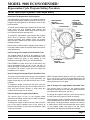
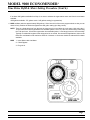
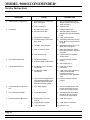
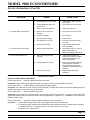
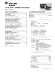
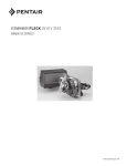
MODEL 9000 Service Manual IMPORTANT: Fill in pertinent information on page 2 for future reference. MODEL 9000 ECONOMINDER Job Specification Sheet * JOB NO. __________________________________________________________ * MODEL NO. _______________________________________________________ * WATER TEST ______________________________________________________ * CAPACITY PER UNIT_____________ MAX. ___________PER REGENERATION * MINERAL TANK SIZE DIA.________ HEIGHT_________ * BRINE TANK SIZE & SALT SETTING PER REGENERATION _________________________________ * 9000 CONTROL VALVE SPECIFICATIONS 1. Type of Timer A) 82 minute available regeneration time, 1/15 RPM B) 164 minute available regeneration time, 1/30 RPM 2. Type of Meter (see page 23) A) 3/4″ meter *Std. range 125 to 2,100 gal. setting *Ext. range 625 to 10,625 gal. setting B) 1″ meter *Std. range 310 to 5,270 gal. setting *Ext. range 1,550 to 26,350 gal. setting 3. Meter Gallon Setting ____________________________ gal. (see pages 6 & 7) 4. Regeneration Program Settings (see page 5) A) Backwash _________________________________ min. B) Brine & Slow Rinse _________________________ min. C) Rapid Rinse _______________________________ min. D) Brine Tank Refill ____________________________ min. 5. Drain Line Flow Control __________________________ gpm 6. Brine Refill Rate________________________________ gpm 7. Injector Size __________________________________ Page 2 Printed in U.S.A. MODEL 9000 ECONOMINDER General, Residential & Commercial Installation Check List WATER PRESSURE: A minimum of 25 pounds of water pressure is required for regeneration valve to operate effectively. ELECTRICAL FACILITIES: A continuous 110 volt, 60 Hertz current supply is required. Make certain the current supply is always hot and cannot be turned off with another switch. EXISTING PLUMBING: Condition of existing plumbing should be free from lime and iron buildup. Piping that is built up heavily with lime and/or iron should be replaced. If piping is clogged with iron, a separate iron filter unit should be installed ahead of the water softener. LOCATION OF SOFTENER AND DRAIN: The softener should be located close to a drain. BY-PASS VALVES: Always provide for the installation of a by-pass valve. CAUTION: Water pressure is not to exceed 120 p.s.i., water temperature is not to exceed 110° F, and the unit cannot be subjected to freezing conditions. Installation and Start-Up Instructions BRASS YOKES TANK #2 WATER METER TANK #1 OUTLET INLET TANK #2 ADAPTER MAIN CONTROL VALVE ADAPTER CLIPS BY-PASS VALVE 1. Place the softener tank where you want to install the unit, making sure the tanks are level and on a firm base. 2. All plumbing should be done in accordance with local plumbing codes. The pipe size for the drain line should be minimum 1/2″. Overhead drains exceeding 4′ above unit require 3/4″ drain line. 3. Both tanks must be the same height and diameter and filled with equal amounts of media. The 1″ distributor tube (1.050 O.D.) should be cut flush with top of each tank. 4. Lubricate the distributor O-Ring seal and tank O-Ring seal with silicone lubricant. Place the main control valve on one tank and the tank adapter on the second tank. 5. NOTE: The 1″ copper tubing to interconnect the tanks must be soldered prior to assembly on the main control valve and tank adapter. There should be a minimum of 1″ distance between tanks on final assembly. 6. Solder joints near the drain must be done prior to connecting the Drain Line Flow Control fitting. Leave at least 6″ between the DLFC and solder joints when soldering. Failure to do this could cause damage to the drain module. 7. Teflon tape is the only sealant to be used on the drain fitting. 8. Make sure that the floor is clean beneath the salt storage tank and that it is level. 9. Place approximately 1″ of water above the grid plate (if used) in your salt tank. Salt may be placed in the unit at this time. 10. On units with a by-pass, place in by-pass position. Turn on the main water supply. Open a cold soft water tap nearby and let run a few minutes or until the system is free from foreign material (usually solder) that may have resulted from the installation. 11. Place the by-pass in service position and let water flow into the mineral tanks. When water flow stops, open a cold water tap nearby and let run until air pressure is relieved. 12. Electrical: All electrical connections must be connected according to codes. Plug unit into electrical outlet. Do not insert meter cable into the meter yet. Page 3 Printed in U.S.A. MODEL 9000 ECONOMINDER General, Residential & Commercial Installation Check List (Cont’d.) 14. Cycle timer into backwash position. Turn manual knob (figure 1) so that the micro switch is riding on the 1st set of pins (figure 2). In this position the tanks will switch (lower piston) and the control valve will move to the backwash position (upper piston). You must wait until the positioning of upper and lower pistons has stopped before advancing the timer further. If advanced too fast the control will not home into the service position (it will not advance to any other position). To correct this, rotate the manual knob back to service and start again into backwash. Note: once valve has positioned itself into the backwash cycle, the homing circuit is locked in. 13. Tank #1 has control valve. Tank #2 has the adapter. Look on the right side of the control valve, it has indicators which tells you which position the control valve is in during regeneration and which tank is IN SERVICE. Photo on the right indicates the valve is in the service position and tank #1 is supplying conditioned water. Tank #2 is on standby. With all the air backwashed out, slowly cycle the timer to the brine position; rapid rinse; and brine tank refill. You must wait for the control drive motor to position itself in each cycle and stop, before advancing on to the next position. Once back in the service position, cycle the control valve again into the backwash position. The tanks will switch again, and you will backwash the air head out of the other tank. Cycle the control back to the service position. Leave the timer in the open position. DO NOT INSERT METER CABLE YET. BRINE & RINSE SECTION (2 MIN. PER HOLE) PIN STORAGE PROGRAM WHEEL FOR CONTROL OF REGENERATION CYCLE RAPID RINSE SECTION (2 MIN. PER PIN) BRINE TANK REFILL SECTION (2 MIN. PER HOLE) NOTE: Make sure the meter cable is not inserted in the meter dome. Swing the timer out to expose the program wheel Figure 2 (to swing timer out) grab onto the lower right corner of timer face Figure 1 and pull outward. BACKWASH SECTION (2 MIN. PER PIN) NOTE: 2 motors are available, 1/15 RPM will have a 82 min. reg. time available. Page 4 Printed in U.S.A. MODEL 9000 ECONOMINDER Regeneration Cycle Program Setting Procedure (Brine Tank Refill Separate From Rapid Rinse) How To Set The Regeneration Cycle Program: The regeneration cycle program on your water conditioner has been factory preset, however, portions of the cycle or program may be lengthened or shortened in time to suit local conditions. BRINE & RINSE SECTION (2 MIN. PER HOLE) PIN STORAGE To expose cycle program wheel, grasp timer in lower right hand corner and pull, releasing snap retainer and swinging timer to the left. Meter cable must be removed from meter dome before opening timer. PROGRAM WHEEL FOR CONTROL OF REGENERATION CYCLE RAPID RINSE SECTION (2 MIN. PER PIN) To change the regeneration cycle program, the program wheel must be removed. Grasp program wheel and squeeze protruding lugs towards center, lift program wheel off timer. (Switch arms may require movement to facilitate removal.) Return timer to closed position engaging snap retainer in back plate. Make certain all electrical wires locate above snap retainer post. BRINE TANK REFILL SECTION (2 MIN. PER HOLE) How To Change The Length Of The Backwash Time: The program wheel as shown in the drawing is in the service position. As you look at the numbered side of the program wheel, the group of pins starting at zero determines the length of time your unit will backwash. BACKWASH SECTION (2 MIN. PER PIN) FOR EXAMPLE: If there are six pins in this section, the time of backwash will be 12 min. (2 min. per pin). To change the length of backwash time, add or remove pins as required. The number of pins times two equals the backwash time in minutes. How To Change The Length Of Brine And Rinse Time: The group of holes between the last pin in the backwash section and the second group of pins determines the length of time that your unit will brine and rinse. (2 min. per hole.) NOTE: Program wheels having 0 to 82 min. cycle times, use “1” min. per pin or hole to set regeneration times. The layout of pins and holes on the program wheel follow the same procedure as on this page. To change the length of brine and rinse time, move the rapid rinse group of pins to give more or fewer holes in the brine and rinse section. Number of holes times two equals brine and rinse time in minutes. How To Change The Length Of Brine Tank Refill Time: How To Change The Length Of Rapid Rinse: The second group of pins on the program wheel determines the length of time that your water conditioner will rapid rinse. (2 min. per pin.) To change the length of rapid rinse time, add or remove pins at the higher numbered end of this section as required. The number of pins times two equals the rapid rinse time in minutes. The second group of holes on the program wheel determines the length of time that your water conditioner will refill the brine tank (2 min. per hole.) To change the length of refill time, move the two pins at the end of the second group of holes as required. The regeneration cycle is complete when the outer microswitch is tripped by the two pin set at end of the brine tank refill section. The program wheel, however, will continue to rotate until the inner micro-switch drops into the notch on the program wheel. See page 6 for salt setting calculations, and page 24 for general timer settings. Page 5 Printed in U.S.A. MODEL 9000 ECONOMINDER Time Brine Refill & Meter Setting Procedure PROGRAMMING 1. Your control valve has been factory set for backwash; brine and slow rinse; rapid rinse and brine tank fill times. See the control valve specification sheet (pg. 24). Any of these times can be changed by repositioning the pins and holes or adding more pins (see pg. 5). Note that two different speed timer motors are used, one allows for an 82 minute maximum regeneration time (each pin or hole = 1 min.). The other allows for 164 minute maximum regeneration time (each pin or hole = 2 min.). 2. The 9000 Control has a separate brine tank fill cycle. Your desired salt setting must be calculated, using the blue (.25 gpm) or black (.5 gpm) or red (1.0 gpm) rate of refill (in gpm) times your timer setting. Then using one gallon of fresh water dissolving approximately 3 lbs. salt, calculate your refill time. ie: A desired 9 lb. salt setting: The unit has a .5 gpm refill rate, we will need a 3 gallon fill. (3 gal. x 3 lb./gal. = 9 lb. salt). The timer refill section would have to be set at 6 minutes. (6 min x .5 gpm = 3 gal. fill) Note: There always must be 2 pins at the end of your refill time. This is to stop the fill cycle. With your regeneration times now set, place timer back to its original position, making sure the lower right hand corner snaps back into the backplate and the meter cable slides through the backplate and does not bind. 3. Setting the gallon wheel Knowing the amount of resin you have in each tank and your salt setting per regeneration, calculate the gallons available, using the following capacities as a guide: One Cubic Foot of Resin Salt Setting at 15 lb 10 lb 8 lb 6 lb Gallons available = Capacity per Regeneration. Compensated Hardness of H2O Capacity per Regeneration 30,000 grains 27,000 grains 24,000 grains 20,000 grains ie: 24 grain water; each tank having 1 cubic foot of resin and salted at 8 lb. of salt, yielding a usable 24,000 grain capacity: 1,000 gallons available = 24,000 gr. capacity 24 gr. water DO NOT SET THIS FIGURE - GO TO STEP 4 3. Since the 9000 Valve regenerates with soft water from the other tank, you must subtract the water used for regeneration. Take each of your regeneration cycles and calculate the water used. (Use the injector Slow Rinse rate chart supplied, see pg. 24.) ie: Unit is set up for a 10 tank having 2.4 gpm backwash, #1 injector, .5 gpm refill, timer set up for 8 min. backwash, 54 min. brine and rinse, 6 min. rapid rinse, 6 min. brine tank fill. A. Backwash - 8 mins. x 2.4 gpm = 19.2 gallons B. Brine and Rinse - 54 mins. x .33 gpm = (See injector chart slow rinse flow, pg. 23) 17.8 gallons C. Rapid Rinse - 6 mins. x 2.4 gpm = 14.4 gallons D. Brine Tank Fill - 6 mins. x .5 gpm = 3.0 gallons Total Regeneration Water = 54.4 gallons Page 6 Printed in U.S.A. MODEL 9000 ECONOMINDER Time Brine Refill & Meter Setting Procedure (Cont’d.) If we have 1000 gallons available from Step 3, we want to subtract the regeneration water used from the total water available. 1000 gallons available - 55. gallons used = 945 gallons setting (in regeneration) 4. NOW set Meter wheel at approximately 950 gallons. Lift the inner dial of the meter program wheel so that you can rotate it freely. Position the white dot opposite the 950 gallon setting (see diag. below). NOTE: There is a slight delay time from the time the meter zero’s out and when the cycle starts. Units using the 1/ 15 rpm motor, 82 minute regeneration time available (tanks 6″ thru 12″) have a 9 minute delay. Units using the 1/30 rpm motor, 180 minute regeneration time available (tanks 13″ and larger) have an 18 minute delay. Typically on residential equipment this delay period is not critical. On commercial applications, this must be taken into consideration and continuous flows for 9 minutes or 18 minutes should be subtracted from water available. NOW 1. Insert Meter cable into Meter. 2. Check Bypass. 3. Plug unit in. Page 7 Printed in U.S.A. MODEL 9000 ECONOMINDER BRINE VALVE FLOW CONTROL DRAIN 1 - SERVICE POSITION Hard water enters the unit at the valve inlet, flows around the lower piston, and down through the mineral in the first tank. Conditioned water enters the center tube through the bottom distributor, flows up through the center tube, around the lower piston, through the meter, and out the valve outlet. The second mineral tank is regenerated and on standby. MINERAL TANK #1 BRINE TANK BRINE VALVE FLOW CONTROL DRAIN 2 - TANKS SWITCHING (the meter has initiated a regeneration) Hard water enters the unit at the valve inlet, flows around the lower piston, through the pipe leading to the second mineral tank, and down through the mineral in the second tank. Conditioned water enters the center tube of the second tank through the bottom distributor, flows up through the center tube, through the pipe leading back to the main valve, around the lower piston, through the meter, and out the valve outlet. The depleted first mineral tank is out of the flow path, and ready for regeneration. MINERAL TANK #1 BRINE TANK Page 8 Printed in U.S.A. MODEL 9000 ECONOMINDER BRINE VALVE FLOW CONTROL DRAIN 3 - BACKWASH Conditioned water from the second mineral tank flows around the lower piston, around the upper piston, through the center of the lower piston, down the center tube, up through the mineral, around the upper piston, and out the drain line. MINERAL TANK #1 BRINE TANK BRINE VALVE FLOW CONTROL DRAIN 4 - BRINE DRAW Conditioned water from the second mineral tank flows around the lower piston, around the upper piston, into the injector housing, and down through the nozzle and throat to draw brine from the brine tank. Brine flows around the upper piston, down through the mineral, into the center tube through the bottom distributor, up the center tube, through the center of the lower piston, through the center of the upper piston, and out through the drain line. MINERAL TANK #1 BRINE TANK Page 9 Printed in U.S.A. MODEL 9000 ECONOMINDER BRINE VALVE FLOW CONTROL DRAIN 5 - SLOW RINSE Conditioned water from the second mineral tank flows around the lower piston, around the upper piston, into the injector housing, down through the nozzle and throat, around the upper piston, down through the mineral, into the center tube through the bottom distributor, up the center tube, through the center of the lower piston, through the center of the upper piston, and out through the drain line. MINERAL TANK #1 BRINE TANK BRINE VALVE FLOW CONTROL DRAIN 6 - RAPID RINSE Conditioned water from the second mineral tank flows around the lower piston, around the upper piston, and down through the mineral in the first tank. Rinse water from the mineral bed enters the center tube through the bottom distributor, flows up the center tube, through the center of the lower piston, through the center of the upper piston, and out through the drain line. MINERAL TANK #1 BRINE TANK Page 10 Printed in U.S.A. MODEL 9000 ECONOMINDER BRINE VALVE FLOW CONTROL DRAIN 7 - BRINE TANK FILL POSITION Conditioned water from the second mineral tank flows around the lower piston, around the upper piston, into the injector housing, through the brine line flow control, through the brine valve, and into to brine tank. No water flows through the first mineral tank. MINERAL TANK #1 BRINE TANK BRINE VALVE FLOW CONTROL DRAIN 8 - SERVICE (TANKS SWITCHED) Hard water enters the unit at the valve inlet, flows around the lower piston, through the pipe leading to the second mineral tank, and down through the mineral in the second tank. Conditioned water enters the center tube of the second tank through the bottom distributor, flows up through the center tube, through the pipe leading back to the main valve, around the lower piston, through the meter, and out the valve outlet. The regenerated first mineral tank is out of the flow path, and ready for use when the second mineral tank becomes depleted. MINERAL TANK #1 BRINE TANK Page 11 Printed in U.S.A. MODEL 9000 ECONOMINDER Drive Assembly (See opposite page for parts list) 24 26 35 25 1 42 2 32 33 39 3 27 4 34 23 29 1 28 6 22 2 3 11 34 5 12 10 15 21 7 8 9 14 16 36 17 18 19 30 Page 12 Printed in U.S.A. 20 MODEL 9000 ECONOMINDER Drive Assembly Parts List Item No. Quantity Part No. 1. . . . . . . . . . . 2 . . . . . . . . . . . 11335 . . . . . . . . . . . . . . . 2. . . . . . . . . . . 2 . . . . . . . . . . . 18564 . . . . . . . . . . . . . . . 3. . . . . . . . . . . 2 . . . . . . . . . . . 13363 . . . . . . . . . . . . . . . 4. . . . . . . . . . . 1 . . . . . . . . . . . 14921 . . . . . . . . . . . . . . . 5. . . . . . . . . . . 1 . . . . . . . . . . . 15019 . . . . . . . . . . . . . . . 6. . . . . . . . . . . 2 . . . . . . . . . . . 18728 . . . . . . . . . . . . . . . 7. . . . . . . . . . . 1 . . . . . . . . . . . 15203 . . . . . . . . . . . . . . . 8. . . . . . . . . . . 1 . . . . . . . . . . . 11838 . . . . . . . . . . . . . . . 9. . . . . . . . . . . 1 . . . . . . . . . . . 15202 . . . . . . . . . . . . . . . 10 . . . . . . . . . . 1 . . . . . . . . . . . 15134 . . . . . . . . . . . . . . . 11 . . . . . . . . . . 1 . . . . . . . . . . . 15135 . . . . . . . . . . . . . . . 12 . . . . . . . . . . 1 . . . . . . . . . . . 14896 . . . . . . . . . . . . . . . 14 . . . . . . . . . . 4 . . . . . . . . . . . 12681 . . . . . . . . . . . . . . . 15 . . . . . . . . . . 2 . . . . . . . . . . . 19367 . . . . . . . . . . . . . . . 16 . . . . . . . . . . 1 . . . . . . . . . . . 15175 . . . . . . . . . . . . . . . 17 . . . . . . . . . . 2 . . . . . . . . . . . 14917 . . . . . . . . . . . . . . . 18 . . . . . . . . . . 1 . . . . . . . . . . . 15199 . . . . . . . . . . . . . . . 19 . . . . . . . . . . 1 . . . . . . . . . . . 14430 . . . . . . . . . . . . . . . 20 . . . . . . . . . . 2 . . . . . . . . . . . 13602 . . . . . . . . . . . . . . . 21 . . . . . . . . . . 1 . . . . . . . . . . . 18739 . . . . . . . . . . . . . . . 1 . . . . . . . . . . . 18738 . . . . . . . . . . . . . . . 1 . . . . . . . . . . . 18737 . . . . . . . . . . . . . . . 22 . . . . . . . . . . 1 . . . . . . . . . . . 15131 . . . . . . . . . . . . . . . 23 . . . . . . . . . . 2 . . . . . . . . . . . 15172 . . . . . . . . . . . . . . . 24 . . . . . . . . . . 2 . . . . . . . . . . . 10340 . . . . . . . . . . . . . . . 25 . . . . . . . . . . 1 . . . . . . . . . . . 10218 . . . . . . . . . . . . . . . 26 . . . . . . . . . . 2 . . . . . . . . . . . 10339 . . . . . . . . . . . . . . . 27 . . . . . . . . . . 7 . . . . . . . . . . . 15331 . . . . . . . . . . . . . . . 28 . . . . . . . . . . 1 . . . . . . . . . . . 15133 . . . . . . . . . . . . . . . 29 . . . . . . . . . . 1 . . . . . . . . . . . 15132 . . . . . . . . . . . . . . . 30 . . . . . . . . . . 1 . . . . . . . . . . . 13547 . . . . . . . . . . . . . . . 31 . . . . . . . . . . 1 . . . . . . . . . . . 15810 . . . . . . . . . . . . . . . 32 . . . . . . . . . . 1 . . . . . . . . . . . 15323 . . . . . . . . . . . . . . . 33 . . . . . . . . . . 1 . . . . . . . . . . . 15368 . . . . . . . . . . . . . . . 34 . . . . . . . . . . 2 . . . . . . . . . . . 15372 . . . . . . . . . . . . . . . 35 . . . . . . . . . . 1 . . . . . . . . . . . 15216 . . . . . . . . . . . . . . . 1 . . . . . . . . . . . 15425 . . . . . . . . . . . . . . . 36 . . . . . . . . . . 2 . . . . . . . . . . . 15692 . . . . . . . . . . . . . . . 37 . . . . . . . . . . 1 . . . . . . . . . . . 10302 . . . . . . . . . . . . . . . 38 . . . . . . . . . . . . . . . . . . . . . . . . . . . . . . . . . . . . . . . . . . . . 39 . . . . . . . . . . 1 . . . . . . . . . . . 16433 . . . . . . . . . . . . . . . 40 . . . . . . . . . . 1 . . . . . . . . . . . 18699-XX . . . . . . . . . . . . 41 . . . . . . . . . . 1 . . . . . . . . . . . 14779-XX . . . . . . . . . . . . 1 . . . . . . . . . . . 19291-020 . . . . . . . . . . . . 42 . . . . . . . . . . 2 . . . . . . . . . . . 15173 . . . . . . . . . . . . . . . Description Screw, #4-40 Screw, Hex Washer #6-20 Washer Piston Rod Link, Upper Piston Rod Link, Lower Nut, Clip, #8-32 Wiring Harness - Timer Power Cord Wiring Harness - Drive Drive Gear, Assembly, Lower Drive Gear Geneva Wheel Wire Connector Cover Screw Assembly Position Decal Retaining Ring Ground Plate Screw, Hex Washer #6 Screw, Round Hd #6-32 Drive Motor - 220V., 50 Hz Drive Motor - 120V., 60 Hz Drive Motor 24V., 50-60 Hz Control Panel Screw, Flat Hd #4-40 Washer, Lock #4 Micro Switch Nut, Hex #4-40 Screw, Hex Washer #10-24 Drive Gear, Assembly, Upper Triple Cam Strain Relief Retaining Ring, Drive Gear (not shown) Guide Pin Upper Piston Rod Link Cable Guide Washer, Thrust Meter Cable Assy. - 1″ Meter Meter Cable Assy. - 3/4″ Meter Spacer Insulator (not shown) Not Assigned Micro Switch, Program Cover, Top (Now Shown) Cover, Bottom (Not Shown) Cover, 1 Piece, Black Screw Page 13 Printed in U.S.A. MODEL 9000 ECONOMINDER Control Valve Assembly (See opposite page for parts list) 45 6 1 2 7 26 3 43 44 4 40 5 41 39 6 31 28 42 38 37 36 7 29 29 47 16 10 16 21 27 22 23 19 3 18 9 17 15 14 12 32 20 11 8 35 34 16 30 13 5 Page 14 Printed in U.S.A. 24 48 25 MODEL 9000 ECONOMINDER Control Valve Assembly Parts List Item No. Quantity Part No. 1 . . . . . . . . . 1 . . . . . . . . . . . 14861-01 . . . . . . . . . . . . 2 . . . . . . . . . 1 . . . . . . . . . . . 14914 . . . . . . . . . . . . . . . 3 . . . . . . . . . 2 . . . . . . . . . . . 14309 . . . . . . . . . . . . . . . 2 . . . . . . . . . . . 16590 . . . . . . . . . . . . . . . 4 . . . . . . . . . 1 . . . . . . . . . . . 14919 . . . . . . . . . . . . . . . 5 . . . . . . . . . 2 . . . . . . . . . . . 13446 . . . . . . . . . . . . . . . 2 . . . . . . . . . . . 13446-01 . . . . . . . . . . . . 6 . . . . . . . . . 12 . . . . . . . . . . 14241 . . . . . . . . . . . . . . . 12 . . . . . . . . . . 14241-01 . . . . . . . . . . . . 7 . . . . . . . . . 16 . . . . . . . . . . 13242 . . . . . . . . . . . . . . . 16 . . . . . . . . . . 18759 . . . . . . . . . . . . . . . 8 . . . . . . . . . 1 . . . . . . . . . . . 14920 . . . . . . . . . . . . . . . 9 . . . . . . . . . 1 . . . . . . . . . . . 14905 . . . . . . . . . . . . . . . 10 . . . . . . . . . 1 . . . . . . . . . . . 11710 . . . . . . . . . . . . . . . 11 . . . . . . . . . 1 . . . . . . . . . . . 12281 . . . . . . . . . . . . . . . 12 . . . . . . . . . 1 . . . . . . . . . . . 11981-01 . . . . . . . . . . . . 13 . . . . . . . . . 1 . . . . . . . . . . . 16098 . . . . . . . . . . . . . . . 14 . . . . . . . . . 1 . . . . . . . . . . . 11973 . . . . . . . . . . . . . . . 15 . . . . . . . . . 1 . . . . . . . . . . . 13165 . . . . . . . . . . . . . . . 16 . . . . . . . . . 3 . . . . . . . . . . . 13302 . . . . . . . . . . . . . . . 17 . . . . . . . . . 1 . . . . . . . . . . . 12550 . . . . . . . . . . . . . . . 18 . . . . . . . . . 1 . . . . . . . . . . . 13167 . . . . . . . . . . . . . . . 19 . . . . . . . . . 1 . . . . . . . . . . . 14925 . . . . . . . . . . . . . . . 20 . . . . . . . . . 1 . . . . . . . . . . . 12626 . . . . . . . . . . . . . . . 21 . . . . . . . . . 1 . . . . . . . . . . . 15215 . . . . . . . . . . . . . . . 22 . . . . . . . . . 1 . . . . . . . . . . . 10914 . . . . . . . . . . . . . . . 10226 . . . . . . . . . . . . . . . 23 . . . . . . . . . 1 . . . . . . . . . . . 10913 . . . . . . . . . . . . . . . 10225 . . . . . . . . . . . . . . . 24 . . . . . . . . . 1 . . . . . . . . . . . 13303 . . . . . . . . . . . . . . . 25 . . . . . . . . . 1 . . . . . . . . . . . 13166 . . . . . . . . . . . . . . . 26 . . . . . . . . . 1 . . . . . . . . . . . 16595 . . . . . . . . . . . . . . . 27 . . . . . . . . . 1 . . . . . . . . . . . 13387 . . . . . . . . . . . . . . . 28 . . . . . . . . . 1 . . . . . . . . . . . 13361 . . . . . . . . . . . . . . . 29 . . . . . . . . . 2 . . . . . . . . . . . 13301 . . . . . . . . . . . . . . . 30 . . . . . . . . . 1 . . . . . . . . . . . 13497 . . . . . . . . . . . . . . . 31 . . . . . . . . . 1 . . . . . . . . . . . 15348 . . . . . . . . . . . . . . . 32 . . . . . . . . . 1 . . . . . . . . . . . 10227 . . . . . . . . . . . . . . . 33 . . . . . . . . . . . . . . . . . . . . . . . . . . . . . . . . . . . . . . . . . . 34 . . . . . . . . . 1 . . . . . . . . . . . 13244 . . . . . . . . . . . . . . . 37 . . . . . . . . . 1 . . . . . . . . . . . 16173 . . . . . . . . . . . . . . . 35 . . . . . . . . . 1. . . . . . . . . . . . . . . . . . . . . . . . . . . . . . . . 36 . . . . . . . . . 1 . . . . . . . . . . . 13245 . . . . . . . . . . . . . . . 1 . . . . . . . . . . . 12977 . . . . . . . . . . . . . . . 38 . . . . . . . . . 1. . . . . . . . . . . . . . . . . . . . . . . . . . . . . . . . 39 . . . . . . . . . 1 . . . . . . . . . . . 13173 . . . . . . . . . . . . . . . 40 . . . . . . . . . 1 . . . . . . . . . . . 10332 . . . . . . . . . . . . . . . 1 . . . . . . . . . . . 15415 . . . . . . . . . . . . . . . 41 . . . . . . . . . 1 . . . . . . . . . . . 10330 . . . . . . . . . . . . . . . 1 . . . . . . . . . . . 16124 . . . . . . . . . . . . . . . 42 . . . . . . . . . 1 . . . . . . . . . . . 10329 . . . . . . . . . . . . . . . 1 . . . . . . . . . . . 16123 . . . . . . . . . . . . . . . 43 . . . . . . . . . 1 . . . . . . . . . . . 14928 . . . . . . . . . . . . . . . 44 . . . . . . . . . 1 . . . . . . . . . . . 14906 . . . . . . . . . . . . . . . 45 . . . . . . . . . 4 . . . . . . . . . . . 15137 . . . . . . . . . . . . . . . 46 . . . . . . . . . 1 . . . . . . . . . . . 16140 . . . . . . . . . . . . . . . 47 . . . . . . . . . 1 . . . . . . . . . . . 15471 . . . . . . . . . . . . . . . 48 . . . . . . . . . 1 . . . . . . . . . . . 13315 . . . . . . . . . . . . . . . Description Valve Body Piston, Upper Piston Rod Retainer Piston Rod Retainer, HW Piston Rod, Upper End Plug Assy. End Plug Assy., HW Spacer Spacer, HW Seal Seal, HW Piston Rod, Lower Piston, Lower O-Ring, -215 O-Ring, -338 Retaining Ring Washer, Brine Valve (Nylon) Spring, Brine Valve Brine Valve Cap O-Ring, -014 Quad Ring, -009 Brine Valve Spacer Brine Valve Stem Brine Valve Seat Injector Body Injector Throat - Specify Size pg. 24 Injector Throat, SS Injector Nozzle, Specify Size pg. 24 Injector Nozzle, SS O-Ring, -021 Injector Cover Spacer Screw, Hex Hd #10-24 Spacer, Injector O-Ring, -011 Air Disperser O-Ring, -563 Injector Screen Not Assigned B.L.F.C. Fitting B.L.F.C. Fitting - Bored* B.L.FC. Button - Specify Size pg. 24 B.L.F.C. Button Retainer O-Ring, -015 D.L.F.C. Button - Specify Size pg. 24 D.L.F.C. Button Retainer Tube Insert - 3/8″ Note: For Hot Water Delete Items Tube Insert - 1/2″* 41 & 42 and use Ferrule - 3/8″ 18698 . . Nut & Sleeve Assy. 3/8″ Ferrule - 1/2″* 15414 . . Nut & Sleeve Assy. 1/2″ Tube Nut - 3/8″ Tube Nut - 1/2″* * These parts are used with #4 Stub End Plug Injector and 2 GPM or larger End Plate Brine Line Flow Control Screw, Hex Washer, #10-24 (B.L.F.C.). Items 34, 35 and 36 Adapter, 1/2″ T to 1/4″ P (not shown)* are not used. Brine Valve Stand Off Screw, Hex Washer, #10-24 Page 15 Printed in U.S.A. MODEL 9000 ECONOMINDER Second Tank Adapter Assembly 1 7 2 6 8 2 3 2 2 7 8 4 6 5 6 7 2 8 5 2 6 2 8 7 2 PARTS LIST Item No. Quantity Part No. Description 1 . . . . . . . . . . . 1. . . . . . . . . . . . 14864-01 . . . . . . . . . . . . . 2nd Tank Adapter 2 . . . . . . . . . . . 8. . . . . . . . . . . . 13305. . . . . . . . . . . . . . . . O-Ring, -119 3 . . . . . . . . . . . 1. . . . . . . . . . . . 11710. . . . . . . . . . . . . . . . O-Ring, -215 4 . . . . . . . . . . . 1. . . . . . . . . . . . 12281. . . . . . . . . . . . . . . . O-Ring, -338 5 . . . . . . . . . . . 2. . . . . . . . . . . . 13708-40 . . . . . . . . . . . . . Yoke 1. . . . . . . . . . . . 15823-XX. . . . . . . . . . . . . Yoke Assy. Specify Tank Size 6 . . . . . . . . . . . 4. . . . . . . . . . . . 13255. . . . . . . . . . . . . . . . Hold-Down Clip 7 . . . . . . . . . . . 4. . . . . . . . . . . . 14202. . . . . . . . . . . . . . . . Screw, Hex Hd #8-32 8 . . . . . . . . . . . 4. . . . . . . . . . . . 15078. . . . . . . . . . . . . . . . Coupling 9...........2 . . . . . . . . . . . . . . . . . . . . . . . . . . . . . . . . . . Pipe - 1″ Copper Cut to Length Page 16 Printed in U.S.A. MODEL 9000 ECONOMINDER Air Check 13 11 12 10 1 2 3 5 4 6 PARTS LIST Item No. Quantity 1. . . . . . . . . . . 1 . . . . . . . . . . . 2. . . . . . . . . . . 1 . . . . . . . . . . . 3. . . . . . . . . . . 1 . . . . . . . . . . . 4. . . . . . . . . . . 1 . . . . . . . . . . . 5. . . . . . . . . . . 1 . . . . . . . . . . . 1 ........... 6. . . . . . . . . . . 1 . . . . . . . . . . . 1 ........... 10 11 12 13 14 ....................... ....................... ....................... ....................... ....................... Part No. 10332 . . . . . . . . . . . . . . . 10330 . . . . . . . . . . . . . . . 10329 . . . . . . . . . . . . . . . Not Supplied . . . . . . . . . . 12794 . . . . . . . . . . . . . . . 13555 . . . . . . . . . . . . . . . 60002 . . . . . . . . . . . . . . . 60003 . . . . . . . . . . . . . . . Description Tube Insert 3/8″ Ferrule 3/8″ Tube Nut 3/8″ Brine Line Tube (3/8 Flexible Tube) 90° Elbow - 3/8″ T to 3/8″ T 90° Elbow - 3/8″ T to 3/8″ T, HW #500 Air Check Assembly #500 Air Check Assembly, HW For Use With 2 GPM Flow Control 15415 . . . . . . . . . . . . . . . Tube Insert 1/2″ 16123 . . . . . . . . . . . . . . . Ferrule 1/2″ 16124 . . . . . . . . . . . . . . . Tube Nut 1/2″ 15413 . . . . . . . . . . . . . . . Elbow 60009 . . . . . . . . . . . . . . . #900 Air Check Assembly 60009-01 . . . . . . . . . . . . . #900 Air Check Assembly, HW Page 17 Printed in U.S.A. MODEL 9000 ECONOMINDER 1″ Meter Assembly 1 2 12 3 11 8 10 4 8 8 5 10 11 8 7 6 PARTS LIST Item No. Quantity Part No. Description 1 . . . . . . . . . . . 4 . . . . . . . . . . . 12112. . . . . . . . . . . . . . . . Screw, Hex Hd #10-24 2 . . . . . . . . . . . 1 . . . . . . . . . . . 15218. . . . . . . . . . . . . . . . Meter Cover Assy. 15237. . . . . . . . . . . . . . . . Meter Cover Assy. (Ext. range) 3 . . . . . . . . . . . 1 . . . . . . . . . . . 13847. . . . . . . . . . . . . . . . O-Ring, -137 4 . . . . . . . . . . . 1 . . . . . . . . . . . 13509. . . . . . . . . . . . . . . . Impeller 1 . . . . . . . . . . . 13509-01 . . . . . . . . . . . . . Impeller, HW 5 . . . . . . . . . . . 1 . . . . . . . . . . . 13882. . . . . . . . . . . . . . . . Impeller Post 6 . . . . . . . . . . . 1 . . . . . . . . . . . 15043. . . . . . . . . . . . . . . . Meter Body 1″ - 11-1/2 N.P.T. 1 . . . . . . . . . . . 15043-10 . . . . . . . . . . . . . Meter Body 1″ - 11 B.S.P. 7 . . . . . . . . . . . 1 . . . . . . . . . . . 14960. . . . . . . . . . . . . . . . Flow Straightener 8 . . . . . . . . . . . 4 . . . . . . . . . . . 13305. . . . . . . . . . . . . . . . O-Ring, -119 9 . . . . . . . . . . . . . . . . . . . . . . . . . . . . . . . . . . . . . . . . . . . . . Not Assigned 10. . . . . . . . . . . .2 . . . . . . . . . . . 15078. . . . . . . . . . . . . . . . Coupling 11. . . . . . . . . . . 2 . . . . . . . . . . . 13255. . . . . . . . . . . . . . . . Adapter Clip 12. . . . . . . . . . . 2 . . . . . . . . . . . 14202. . . . . . . . . . . . . . . . Screw, Hex Hd #8-32 Page 18 Printed in U.S.A. 12 MODEL 9000 ECONOMINDER 3/4″ Meter Assembly 1 2 3 9 4 5 6 7 8 PARTS LIST Item No. Quantity 1. . . . . . . . . . . 4 . . . . . . . . . . . 2. . . . . . . . . . . 1 . . . . . . . . . . . ........................ 3. . . . . . . . . . . 1 . . . . . . . . . . . 4. . . . . . . . . . . 1 . . . . . . . . . . . 5. . . . . . . . . . . 4 . . . . . . . . . . . 6. . . . . . . . . . . 4 . . . . . . . . . . . 7. . . . . . . . . . . 1 . . . . . . . . . . . 8. . . . . . . . . . . 4 . . . . . . . . . . . 9. . . . . . . . . . . 1 . . . . . . . . . . . Part No. 12473 . . . . . . . . . . . . . . . 14038 . . . . . . . . . . . . . . . 15150 . . . . . . . . . . . . . . . 13847 . . . . . . . . . . . . . . . 13509 . . . . . . . . . . . . . . . 13314 . . . . . . . . . . . . . . . 13255 . . . . . . . . . . . . . . . 13821 . . . . . . . . . . . . . . . 13305 . . . . . . . . . . . . . . . 14613 . . . . . . . . . . . . . . . Description Screw, Hex Washer #10-24 Meter Cover Assembly - Standard Meter Cover Assembly - Extended Range O-Ring, -137 Impeller Screw, Hex Washer #8-18 Adapter Clip Meter Body O-Ring, -119 Flow Straightener Page 19 Printed in U.S.A. MODEL 9000 ECONOMINDER Timer Assembly (See opposite page for parts list) 6 5 7 8 9 10 11 4 12 18 13 14 15 19 16 2 20 1 17 17 3 22 23 24 25 26 28 26 26 29 27 32 33 30 35 31 36 38 37 39 41 20 40 Page 20 Printed in U.S.A. MODEL 9000 ECONOMINDER Timer Assembly Parts List Item No. Quantity 1. . . . . . . . . . . .1 . . . . . . . . . . . . 2. . . . . . . . . . . .1 . . . . . . . . . . . . 3. . . . . . . . . . . .1 . . . . . . . . . . . . 4. . . . . . . . . . . .1 . . . . . . . . . . . . 5. . . . . . . . . . . .1 . . . . . . . . . . . . 6. . . . . . . . . . . .1 . . . . . . . . . . . . 7. . . . . . . . . . . .1 . . . . . . . . . . . . 8. . . . . . . . . . . .1 . . . . . . . . . . . . 9. . . . . . . . . . . .1 . . . . . . . . . . . . 10 . . . . . . . . . . . 1 . . . . . . . . . . . . 11 . . . . . . . . . . . 1 . . . . . . . . . . . . 12 13 14 15 16 17 18 19 20 22 23 24 25 26 27 28 29 30 31 32 33 35 36 37 38 39 40 41 42 43 Part No. Description 13870-03. . . . . . . . . . . . . . .Timer Housing Assy. 17870 . . . . . . . . . . . . . . . . .Label - Capacity Gallons 15465 . . . . . . . . . . . . . . . . .Label - Caution 16930 . . . . . . . . . . . . . . . . .Label - Instruction 15227 . . . . . . . . . . . . . . . . .Actuator Plate 10300 . . . . . . . . . . . . . . . . .Screw, Hex Washer #8 17513 . . . . . . . . . . . . . . . . .Spring Clip 15407 . . . . . . . . . . . . . . . . .Washer, Plain #4 15228 . . . . . . . . . . . . . . . . .Spring 15224-01. . . . . . . . . . . . . . .Drive Gear - Program Wheel 15967 . . . . . . . . . . . . . . . . .Gallon Label 3/4″ Meter 15968 . . . . . . . . . . . . . . . . .Gallon Label 3/4″ Meter - Ext. Range 15969 . . . . . . . . . . . . . . . . .Gallon Label 1″ Meter 15970 . . . . . . . . . . . . . . . . .Gallon Label 1″ Meter - Ext. Range . . . . . . . . . . . 1 . . . . . . . . . . . . 15956 . . . . . . . . . . . . . . . . .Adjusting Disc . . . . . . . . . . . 1 . . . . . . . . . . . . 16218 . . . . . . . . . . . . . . . . .Program Wheel Cover . . . . . . . . . . . 2 . . . . . . . . . . . . 17054 . . . . . . . . . . . . . . . . .Screw, #4-40 . . . . . . . . . . . 1 . . . . . . . . . . . . 13806 . . . . . . . . . . . . . . . . .Program Wheel Retainer . . . . . . . . . . . 1 . . . . . . . . . . . . 13748 . . . . . . . . . . . . . . . . .Screw, Flat Hd #6-20 . . . . . . . . . . . 2 . . . . . . . . . . . . 11999 . . . . . . . . . . . . . . . . .Button Decal . . . . . . . . . . . 1 . . . . . . . . . . . . 15223 . . . . . . . . . . . . . . . . .Cycle Actuator Gear . . . . . . . . . . . 1 . . . . . . . . . . . . 13886-01. . . . . . . . . . . . . . .Knob . . . . . . . . . . . 4 . . . . . . . . . . . . 13296 . . . . . . . . . . . . . . . . .Screw, Hex Washer #6-20 . . . . . . . . . . . 1 . . . . . . . . . . . . 17724 . . . . . . . . . . . . . . . . .Drive Pinion . . . . . . . . . . . 1 . . . . . . . . . . . . 17723 . . . . . . . . . . . . . . . . .Drive Pinion Clutch . . . . . . . . . . . 1 . . . . . . . . . . . . 14276 . . . . . . . . . . . . . . . . .Spring - Meter Clutch . . . . . . . . . . . 1 . . . . . . . . . . . . 14253 . . . . . . . . . . . . . . . . .Retainer . . . . . . . . . . . 3 . . . . . . . . . . . . 14087 . . . . . . . . . . . . . . . . .Insulator . . . . . . . . . . . 1 . . . . . . . . . . . . 15314 . . . . . . . . . . . . . . . . .Switch . . . . . . . . . . . 1 . . . . . . . . . . . . 15320 . . . . . . . . . . . . . . . . .Switch . . . . . . . . . . . 2 . . . . . . . . . . . . 11413 . . . . . . . . . . . . . . . . .Screw, Pan Hd #4-40 . . . . . . . . . . . 1 . . . . . . . . . . . . 13018 . . . . . . . . . . . . . . . . .Idler Shaft . . . . . . . . . . . 1 . . . . . . . . . . . . 18563 . . . . . . . . . . . . . . . . .Spring - Idler Shaft . . . . . . . . . . . 1 . . . . . . . . . . . . 13017 . . . . . . . . . . . . . . . . .Idler Gear . . . . . . . . . . . 1 . . . . . . . . . . . . 13164 . . . . . . . . . . . . . . . . .Drive Gear . . . . . . . . . . . 1 . . . . . . . . . . . . 13887 . . . . . . . . . . . . . . . . .Motor Mtg. Plate . . . . . . . . . . . 1 . . . . . . . . . . . . 18743 . . . . . . . . . . . . . . . . .Motor - 120V 60 Hz. - 1/30 RPM 18824 . . . . . . . . . . . . . . . . .Motor - 220V 50 Hz. - 1/30 RPM 19170 . . . . . . . . . . . . . . . . .Motor - 120V 60 Hz. - 1/15 RPM 18825 . . . . . . . . . . . . . . . . .Motor - 220V 50 Hz. - 1/15 RPM 19169 . . . . . . . . . . . . . . . . .Motor - 24V 60Hz - 1/15 RPM 19168 . . . . . . . . . . . . . . . . .Motor - 24V 50Hz - 1/15 RPM . . . . . . . . . . . 2 . . . . . . . . . . . . 13278 . . . . . . . . . . . . . . . . .Screw, #6-32 . . . . . . . . . . . 1 . . . . . . . . . . . . 14265 . . . . . . . . . . . . . . . . .Spring Clip . . . . . . . . . . . 1 . . . . . . . . . . . . 15055 . . . . . . . . . . . . . . . . .Main Drive Gear . . . . . . . . . . . 1 . . . . . . . . . . . . 19210-05. . . . . . . . . . . . . . .Program Wheel Assembly - 180 min. 1 . . . . . . . . . . . . 19210-02. . . . . . . . . . . . . . .Program Wheel Assembly - 90 min. . . . . . . . . . . . 23 . . . . . . . . . . . 15493 . . . . . . . . . . . . . . . . .Roll Pin . . . . . . . . . . . . . . . . . . . . . . . . . . . . . . . . . . . . . . . . . . . . . . .Not Assigned . . . . . . . . . . . 1 . . . . . . . . . . . . 14430 . . . . . . . . . . . . . . . . .Screw, Hex Washer, #6 (Ground, Nut Shown) 15203 . . . . . . . . . . . . . . . . .Harness 12681 . . . . . . . . . . . . . . . . .Wire Nuts Page 21 Printed in U.S.A. MODEL 9000 ECONOMINDER Service Instructions PROBLEM 1. 2. 3. Softener Fails To Regenerate. Hard Water. Unit Used Too Much Salt. CAUSE CORRECTION A. Electrical Service To Unit Has Been Interrupted. A. Assure Permanent Electrical Service (Check Fuse, Plug, Pull Chain or Switch). B. Timer Is Defective. B. Replace Timer. A. By-Pass Valve is Open. A. Close By-Pass Valve. B. No Salt in Brine Tank. B. Add Salt To Brine Tank and Maintain Salt Level Above Water Level. C. Injector Screen Plugged. C. Clean Injector Screen. D. Insufficient Water Flowing Into Brine Tank D. Check Brine Tank Fill Time And Clean Brine Line Flow Control If Plugged. E. Hot Water Tank Hardness. E. Repeated Flushings Of The Hot Water Tank is Required. F. F. Leak At Distributor Tube. Make Sure Distributor Tube Is Not Cracked. Check O-Ring And Tube Pilot. G. Internal Valve Leak. G. Replace Seals and Spacers And/Or Piston. A. Improper Salt Setting. A. Check Salt Usage and Salt Setting. B. Excessive Water in Brine Tank. B. See Problem No. 7. 4. Loss Of Water Pressure. A. Iron Buildup In Line To Water Conditioner. A. Clean Line To Water Conditioner. B. Iron Buildup In Water Conditioner. B. Clean Control and Add Mineral Cleaner to Mineral Bed. Increase Frequency of Regeneration and/or Backwash Time. C. Inlet of Control Plugged Due to Foreign Material Broken Loose From Pipes By Recent Work Done On Plumbing System. C. Remove Pistons and Clean Control. 5. Loss of Mineral Through Drain Line. A. Air In Water System. A. Assure That Well System Has Proper Air Eliminator Control. Check For Dry Well Condition. 6. Iron In Conditioned Water. A. Fouled Mineral Bed. A. Check Backwash, Brine Draw And Brine Tank Fill. Increase Frequency Of Regeneration. 7. Excessive Water In Brine Tank. A. Plugged Drain Line Flow Control. A. Clean Flow Control. B. Plugged Injector System. B. Clean Injector and Screen. C. Timer Not Cycling. C. Replace Timer. Page 22 Printed in U.S.A. MODEL 9000 ECONOMINDER Service Instructions (Cont’d.) PROBLEM 8. 9. Softener Fails To Draw Brine. Control Cycles Continuously. 10. Drain Flows Continuously. CAUSE CORRECTION D. Foreign Material In Brine Valve. D. Replace Brine Valve Seat And Clean Valve. E. Foreign Material In Brine Line Flow Control. E. Clean Brine Line Flow Control. F. F. Power Loss During Brine Fill. Check Power Source. A. Drain Line Flow Control Is Plugged. A. Clean Drain Line Flow Control. B. Injector Is Plugged. B. Clean Injector. C. Injector Screen Plugged. C. Clean Screen. D. Line Pressure Is Too Low. D. Increase Line Pressure To 25 P.S.I. Min. E. Internal Control Leak. E. Change Seals, Spacers and Piston Assembly. A. Broken or Shorted Switch. A. Determine If Switch or Timer Is Faulty and Replace it or Replace Complete Power Head. A. Valve Is Not Programming Correctly. A. Check Timer Program and Positioning of Control. Replace Power Head Assembly If not Positioning Properly. B. Foreign Material In Control. B. Remove Power Head Assembly And Inspect Bore, Remove Foreign Material and Check Control In Various Regeneration Positions. C. Internal Control Leak. C. Replace Seals and Piston Assembly. General Service Hints Problem: Softener Delivers Hard Water. Cause could be that . . . Reserve Capacity Has Been Exceeded. Correction: Check salt dosage requirements and reset program wheel to provide additional reserve. Cause could be that . . . Program Wheel Is Not Rotating With Meter Output. Correction: Pull cable out of meter cover and rotate manually. Program wheel must move without binding and cycle actuator must start the cycle before the clutch releases. Cause could be that . . . Meter Is Not Measuring Flow. Correction: Check output by observing rotation of small gear on front of timer (Note — program wheel must not be against regeneration stop for this check). Each tooth is approximately 75 gallons on 1″ installations. If not performing properly, replace meter. Cause could be that . . . Trip Dog On Program Wheel Is Beyond Cycle Actuator Arm. Correction:1. If power failed during regeneration; reset program wheel and cycle manually. 2. If exceeding system capacity before regeneration was completed; either a) increase system capacity, b) restrict flow rates, or c) change timer from 164 min./cycle to 82 min./cycle. 3. If defective timer; replace timer. Page 23 Printed in U.S.A. MODEL 9000 ECONOMINDER 2 Tank Wiring & Control Information 9000 WIRING DIAGRAM CONTROL INFORMATION Tank Size Dia. Injector Slow Rinse Rate (gpm) B.L.F.C.1 D.L.F.C.2 Timer Motor Timer Setting3 6″ 7″ #0 Red #0 Red .26 gpm .26 gpm .5 gpm .5 gpm 1.2 gpm 1.2 gpm 1/15 rpm 1/15 rpm 8-54-6-6 8-54-6-6 8″ 9″ 10″ #1 White #1 White #1 White .33 gpm .33 gpm .33 gpm .5 gpm .5 gpm .5 gpm 1.5 gpm 2.0 gpm 2.4 gpm 1/15 rpm 1/15 rpm 1/15 rpm 8-54-6-6 8-54-6-6 8-54-6-6 12″ 13″ #2 Blue #2 Blue .64 gpm .64 gpm 1.0 gpm 1.0 gpm 3.5 gpm 4.0 gpm 1/15 rpm 1/30 rpm 8-54-6-6 8-60-6-6 14″ 16″ #3 Yellow #3 Yellow .89 gpm .89 gpm 1.0 gpm 1.0 gpm 5.0 gpm 7.0 gpm 1/30 rpm 1/30 rpm 8-60-6-6 8-70-6-6 1 B.L.F.C. (Brine Line Flow Control). Refill Rate for Filling Brine Tank. 2 D.L.F.C. (Drain Line Flow Control). Backwash and Rapid Rinse Flow Rates. 3 8-54-6-6 Refer to -8 min. Backwash; 54 min. Brine and Slow Rinse; 6 min. Rapid Rinse; 6 min. Brine Tank Refill. Note: Due to varying water conditions, tank sizes and water pressures, the above settings should be used only as a guideline. Page 24 Printed in U.S.A. MODEL 9000 ECONOMINDER Controlled Dimensions Page 25 Printed in U.S.A. MODEL 9000 ECONOMINDER Service Assemblies 60022-25 . . . . . BLFC .25 GPM 60022-50 . . . . . BLFC .50 GPM 60022-100 . . . . BLFC 1.0 GPM For Illustration, See Page 14 1 . . . . . . .12094 . . . . . . . . Flow Washer .25 GPM 12095 . . . . . . . . Flow Washer .50 GPM 12097 . . . . . . . . Flow Washer 1.0 GPM 1 . . . . . . .12977 . . . . . . . . O-Ring - 015 1 . . . . . . .13244 . . . . . . . . Adapter, BLFC 1 . . . . . . .13245 . . . . . . . . Retainer, BLFC Button 60350 . . . . . . . . Brine Valve Assy, 9000 For Illustration, See Page 14 1 . . . . . . .11973 . . . . . . . . Spring, Brine Valve 1 . . . . . . .11981 . . . . . . . . Retaining Ring 1 . . . . . . .16095 . . . . . . . . Washer, Plain #10 Nylon 1 . . . . . . .12550 . . . . . . . . Quad Ring, -009 1 . . . . . . .12626 . . . . . . . . Seat, Brine Valve 1 . . . . . . .13165 . . . . . . . . Cap, Brine Valve 1 . . . . . . .13167 . . . . . . . . Spacer, Brine Valve 2 . . . . . . .13302 . . . . . . . . O-Ring, -014 1 . . . . . . .14925 . . . . . . . . Brine Valve Stem, 9000 60400 . . . . . . . . Piston Assy, 9000 Upper For Illustration, See Page 14 1 . . . . . . . 11335 . . . . . . . . Screw, Fil Hd Mach 4-40 X 3/16 1 . . . . . . . 13446 . . . . . . . . End Plug, White Assy 1 . . . . . . . 14309 . . . . . . . . Retainer, Piston Rod 1 . . . . . . . 14914 . . . . . . . . Piston, Upper 9000 1 . . . . . . . 14919 . . . . . . . . Piston Rod, Upper 1 . . . . . . . 14921 . . . . . . . . Link, Piston Rod 60125 . . . . . . . . Seal & Spacer Kit, 9000 - Upper For Illustration, See Page 14 5 . . . . . . . 13242 . . . . . . . . Seal 4 . . . . . . . 14241 . . . . . . . . Spacer 60421 . . . . . . . . Seal & Spacer Kit, 9000 Lower For Illustration, See Page 14 11 . . . . . . 13242 . . . . . . . . Seal 8 . . . . . . . 14241 . . . . . . . . Spacer 1 . . . . . . . 16595 . . . . . . . . Spacer, 9000 60412 . . . . . . . . 9000 Powerhead Assembly See “Parts Price List” 60385-XXXX. . . Injector/Drain Assy See “Parts Price List” 60375-XX . . . . . 9000, Timer 1/15 RPM 60086 . . . . . . . . 3/4″ Meter, Standard Range 60087 . . . . . . . . 3/4″ Meter, Extended Range For Illustration and Parts See Page 19 60376-XX . . . . . 9000, Timer 1/30 RPM See “Parts Price List” 60136-9000 . . . 9000 Service Repair Kit See “Parts Price List” 6O389. . . . . . . . 1″ Meter, Standard Range 60390 . . . . . . . . 1″ Meter, Extended Range For Illustration and Parts See Page 18 60401 . . . . . . . . Piston Assy, 9000 Lower For Illustration and Parts See Page 14 1 . . . . . . .11335 . . . . . . . . Screw, Fil Hd Mach 4-40 x 3/16 1 . . . . . . .13446 . . . . . . . . End Plug Assy White 1 . . . . . . .14309 . . . . . . . . Retainer, Piston Rod 1 . . . . . . .14905 . . . . . . . . Piston, Lower 9000 1 . . . . . . .14920 . . . . . . . . Piston Rod, Lower 1 . . . . . . .15019 . . . . . . . . Link, Piston Rod Page 26 Printed in U.S.A. DLFC, Flow Washers 12085 . . . . . . . . Flow Washer, 1.2 GPM 12086 . . . . . . . . Flow Washer, 1.5 GPM 12087 . . . . . . . . Flow Washer, 2.0 GPM 12088 . . . . . . . . Flow Washer, 2.4 GPM 12089 . . . . . . . . Flow Washer, 3.0 GPM 12090 . . . . . . . . Flow Washer, 3.5 GPM 12091 . . . . . . . . Flow Washer, 4.0 GPM 12092 . . . . . . . . Flow Washer, 5.0 GPM 12408 . . . . . . . . Flow Washer, 7.0 GPM MODEL 9000 ECONOMINDER Service Assemblies, Hot Water 60612 . . . . . . . . 1″ Meter, Standard Range, HW 60632 . . . . . . . . 1″ Meter, Ext. Range 60401-01 . . . . . Piston Assy, 9000 Lower, HW For Illustration and Parts List See Page 14 1 . . . . . . . 11335 . . . . . . . . Screw, Fil Hd Mach 4-40 x 3/16 1 . . . . . . . 13446-01 . . . . . End Plug Assy White 1 . . . . . . . 16590 . . . . . . . . Retainer, Piston Rod, HW 1 . . . . . . . 14905 . . . . . . . . Piston, Lower 9000 1 . . . . . . . 14920 . . . . . . . . Piston Rod, Lower 1 . . . . . . . 15019 . . . . . . . . Link, Piston Rod 60400-01 . . . . . Piston Assy, 9000 Upper, HW For Illustration, See Page 14 1 . . . . . . . 11335 . . . . . . . . Screw, Fit Hd Mach 4-40 x 3/16 1 . . . . . . . 13446-01 . . . . . End Plug, White Assy 1 . . . . . . . 16590 . . . . . . . . Retainer, Piston Rod 1 . . . . . . . 14914 . . . . . . . . Piston, Upper 9000 1 . . . . . . . 14919 . . . . . . . . Piston Rod, Upper 1 . . . . . . . 14921 . . . . . . . . Link, Piston Rod 60125 HW . . . . Seal & Spacer Kit, 9000 - Upper, HW For Illustration, See Page 14 5 . . . . . . . 18759 . . . . . . . .Seal 4 . . . . . . . 14241-01 . . . . .Spacer 60421 HW . . . . Seal & Spacer Kit, 9000 - Lower, HW For Illustration, See Page 14 11 . . . . . . 18759 . . . . . . . . Seal 8 . . . . . . . 14241-01 . . . . . Spacer 1 . . . . . . . 16595 . . . . . . . . Spacer, 9000 Yoke Assy. 15823-06 . . . . . 6″ Tank & 6″ Tube 15823-08 . . . . . 8″ Tank & 4.26″ Tube 15823-12 . . . . . 6″-12″ Tank & 8-1/2″ Tube 15823-14 . . . . . 14″ Tank & 10-1/2″ Tube 15823-16 . . . . . 16″ Tank & 12-1/2″ Tube Page 27 Printed in U.S.A. P/N 15547 Rev. 4 04/01