1
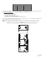
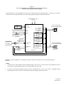
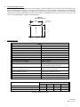
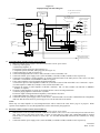
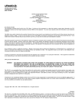
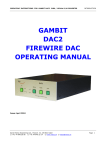
273 Branchport Ave.
Long Branch, N.J. 07740
(800) 631-2148
www.wheelockinc.com
Thank you for using our products.
INSTALLATION INSTRUCTIONS
MODEL MZC-144
MODULAR ZONE CONTROL (3 ZONES EXPANDABLE TO 12 ZONES)
- AND MODEL MZEM-3 ZONE EXPANSION MODULE (3 ZONES)
-ANDMODEL TBM TALK-BACK MODULE
-ANDMODEL MZC-RM MODULAR ZONE CONTROL RELAY MODULE
Use this product according to this instruction manual. Please keep this instruction manual for future reference.
NOTE:
1.
All CAUTIONS and WARNINGS are identified by the
symbol. All warnings are printed in bold capital letters.
APPLICATION INFORMATION:
The Modular Zone Control (MZC-144) is an expandable Zone Control that performs the central control, switching and signaling
required to provide selective Zone Paging, Fixed Group Paging, Logical Zone Group, All Call, Background Music Mute, and
Page Alert Tone Signaling. The MZC-144 provides 3 separate zones of paging, and can be expanded to 12 zones by installing
up to 3 Modular Zone Expansion Modules (MZEM-3). Each MZEM-3 provides a zone group consisting of 3 zones. Each
MZEM-3 provides a background music input for its 3 zone group. The Modular Zone Control Relay Module (MZC-RM)
provides relay operation of the 3 zones in a fixed group.
The MZC-144 can be combined in a master/remote arrangement to create up to 144 zones of paging and relay control. This is
accomplished by using the MZC-CAB cable to daisy chain units together. When the system reaches more than 5 remote units
(72 Zones) a MZC-BOOSTER is required to connect the 5th remote unit to the 6th remote unit.
With the optional (centralized) Talk-Back control circuit installed, the MZC-144 can be programmed to accommodate both One
Way and Talk-Back paging zones. It can also be programmed to be used with a wide variety of system amplifier configurations,
which can include various combinations of 25V/70V/100V central and zone amplifiers and amplified One Way paging speakers.
The MZC-RM provides relay operation of the three (3) zones in a fixed group. The module is capable of either latching or nonlatching operation. Two (2) with Form C contacts and one (1) of either a Normally Open (NO) or Normally Closed (NC)
contact. The MZC-RM can be inserted into the MZC-144 in three (3) different locations. This optional module has been
designed to work with the MZC-144. The MZC-RM will only allow single zone (relay) activation. Through the use of logical
zone groups, the MZC-144 can activate multiple relays during activation of the MZC-RM. Logical zone groups, which can be
up to five (5) entries, are defined by the user. When logical zone groups are programmed for use by the MZC-RM, only single
zone access codes may be used. Fixed zone group and all call activation will cause no change to the status of the relay outputs.
The MZC-144 is compatible with most EKSU, KSU (1A2), and PBX telephone systems. It connects to either an unused loop
start CO port or a 600 ohm low power audio page port. When connected to an unused CO port, DTMF telephones may be used
to operate the MZC-144. When connected to a page port, the page port must provide a dry contact closure and transmit DTMF
tones.
NOTE: The MZC-144 is not designed for connection to an analog port.
Paging is accessed from any telephone by pressing the CO line button (EKSU & KSU), or dialing the number assigned to
paging. Twelve (12) individual zones are selected by dialing 001 thru 012. All Call is selected by dialing 000. The four (4)
zone groups are selected for group paging, by dialing 201 thru 204.
When any Zone, Fixed Zone Group, Logical Zone Group or All Call selection is made, a page alert tone will be heard at all the
speakers in the selected zone. The tone will also be heard at the paging telephone to provide verification of connection to the
selected speakers.
The MZC-144 provides one Fixed Zone Group (3 zones) and can be expanded to 4 Fixed Zone Groups (12 zones), by adding up
to 3 plug-in MZEM-3 expansion modules as shown in Table 1 and Figure 1.
Copyright 1996, 1997, 1998, 2000, 2003 Wheelock Inc. All rights reserved.
P83259 H
Sheet 1 of 26
Group
1
2
3
4
Table 1: Zone Groups
Zones
Qty. of MZEM-3
1, 2, 3
0
4, 5, 6
1
7, 8, 9
2
10, 11, 12
3
Group one (1) of every MZC-144 will always be audio. Groups 2, 3, 4 of each MZC-144 can be audio or a relay (contact closure).
For audio operation use MZEM-3, for relay operation use MZC-RM for each additional zone group.
2. INTERFACE INFORMATION:
The MZC-144 can be connected directly to:
1. A telephone for stand alone paging.
2. A telephone system's unused CO line/trunk port.
3. A telephone system's 600 ohm audio page port (See Figure 12, page 19).
Figure 1 shows the MZC-144 PC Board which includes a built-in zone group 1 (Zones 1, 2, & 3), and illustrates the positions for the
optional MZEM-3, MZC-RM and Talk-Back Module (TBM).
CAUTION: Plugging any Expansion Module in backwards will result in improper operation and failure of the unit.
Figure: 1
PC Board Position of Optional Talk-Back board, Optional MZEM-3 Modules and MZC-RM Modules
P83208
R1
J12
J8
SW1
K1
R7
J11
R3
R1
8
AIM ARROW
TOWARDS GOLD
CONNECTORS
7
6
5
4
3
2
1
TB1
J10
SW2
1 2 3 4
O
N
1 2 3 4
P83206
8
O
N
7
AIM ARROW
TOWARDS GOLD
CONNECTORS
6
5
4
3
2
1 2 3 4
1
O
N
P83206
TB1
SW2
8
AIM ARROW
TOWARDS GOLD
CONNECTORS
7
6
5
4
3
2
1
P83198
P83206
TB1
SW2
P83259 H
Sheet 2 of 26
3.
•
Each zone may be accessed
individually by dialing 001 thru
012.
•
All zones can be accessed
simultaneously for an all call by
dialing 000. Each 3 zone group
(Fixed Zone Group) can be
accessed by dialing 201 thru 204.
•
Table 2 illustrates the three digit
dial access codes. Logical Zone
Groups are also available and are
accessed by 301 thru 325. Logical
Zone Groups are programmed by
you and contain the zones you want
in a group.
This feature is
explained later in the manual under
“Programming Instructions” on
page 23.
Table 2: Dial Access Codes
To Access
All Zones (All Call)
Zone 1
Zone 2
Zone 3
Zone 4
Zone 5
Zone 6
Zone 7
Zone 8
Zone 9
Zone 10
Zone 11
Zone 12
Zone Group 1 (Zones 1, 2 & 3)
Zone Group 2 (Zones 4, 5 & 6)
Zone Group 3 (Zones 7, 8 & 9)
Zone Group 4 (Zones 10, 11 & 12)
Dial
000
001
002
003
004
005
006
007
008
009
010
011
012
201
202
203
204
AUDIO CONFIGURATION DESCRIPTIONS:
The amplifier type (central or zone) is configured for each zone group as described in Table 3.
Table 3: Amplifier Type Group Configuration Function
Group Function
Choices - Per Group
1. Central Amplifier:
Amplifier Type
25V/70V/100V audio output switched to One
Way and/or Talk-Back speakers with line
matching transformers.
2. Zone Amplifier:
600 ohm audio input switched to separate
zone amplifiers connected to One Way
paging speakers with 25V/70V/100V line
matching transformers; or switched to PRM150 line preamplifiers or connected to One
Way paging speaker amplifiers.
If any of the zone groups require central amplification, then the choice of one or two central amplifiers is configured for each of
those groups, as described in Table 4.
Table 4: 1 or 2 Central Amplifiers Group Configuration Function
Group Function
Choices - Per Group
1. One central amplifier for both paging and
1 or 2 Central
background music. Paging in any zone will
Amplifiers
mute music in all zones.
2. Two central amplifiers, one for paging and
one for background music. For One Way
paging, music is muted only in the zone
paged. For Talk-Back paging, music is muted
in all zones.
P83259 H
Sheet 3 of 26
The speech direction function is configured on a per zone basis, as described in Table 5.
Table 5:
Speech Direction Zone Configuration Function
Function
Choices - Per Zone
Speech
1.
One Way paging.
Direction
2.
Talk-Back (optional two-way communication with
hands-free reply).
NOTE: Talk-Back may be chosen only for zones within central amplifier groups and requires the optional Talk-Back module
(TBM).
The MZC-144 has Talk Battery output function for stand alone telephone, unused CO line/trunk port, and 600 ohm audio page
port.
Depending upon system amplifier configuration, the amplifier functions and background music mute operation will vary, as
shown in Table 6.
Table 6:
Amplifier Configurations, Functions, and Music Mute Operation
Amplifier Configuration
Function
Music Mute Operation
(A) One (1) Central Amplifier
Paging & Music
Paging any zone will mute
music in all zones.
(B) Two (2) Central Amplifiers
One for Paging
Music is muted only in the
and
paged zone(s).
One for Music
(C) Zone Amplifiers,
Line Preamplifiers
Speaker Amplifiers
Music is muted only in the
paged zone(s).
Paging & Music
1.
(D) Mixed
(A) & (C) Above
Paging & Music
2.
(E) Mixed
(B) & (C) Above
1.
2.
3.
Paging & Music
Central Amplifier Zones:
Paging mutes music in all
zones.
Zone Amplifier Zones:
Music is muted only in the
paged zone(s).
Music is muted only in the
paged zone(s).
NOTES
The optional Talk-Back function is centrally controlled in the MZC-144, and can be selected
per zone for configurations (A) and (B), as well as the (A) and (B) segments of mixed systems
(D) and (E).
Mixed amplifier configurations (D) and (E) cannot be applied within the same zone group.
When 2 central amplifiers are used, music will be muted in all zones only when a Talk-Back
Zone is accessed.
P83259 H
Sheet 4 of 26
APPLICATION DIAGRAMS:
The following application diagrams show the seven basic system configurations of the MZC-144 and its companion MZEM-3.
All of these configurations are possible with the appropriate configured switch selections. Figures 2, 3, 4, and 5 are typical
configurations using central amplifiers. Figure 6 is a typical configuration using amplified speakers. Figures 7 and 8 are typical
configurations using zone amplifiers.
Figure 2:
One Central Amplifier which has music mute, page input and music input.
(One Way Paging and/or Optional Talk-Back)
In this application, the one central amplifier for both paging and background music has music muting and separate inputs
(volume controls) for paging and music. The system uses speakers with built-in line matching transformers for both One Way
paging, and paging with optional Talk-Back.
FROM TELEPHONE *
24VDC
POWER
SUPPLY
+
GND (+)
-
(-) 24VDC
AMP. 1
OUT
BACKGROUND
MUSIC
SOURCE
(SEE NOTE)
A
25V/70V/100V
CENTRAL AMPLIFIER
W/MUSIC MUTE
AMP. 1
IN
GROUP 1
SYSTEM
MZEM-3
MZEM-3
MZEM-3
#3
#1
#2
GROUP 4 GROUP 3 GROUP 2
4.
TYPICAL SPEAKER
WITH TRANSFORMER
MUSIC
ZONE 1
ZONE 2
ZONE 3
ZONE 1
MUSIC
ZONE 4
ZONE 5
ZONE 6
MUSIC
ZONE 7
ZONE 8
ZONE 9
MUSIC
ZONE 10
ZONE 11
ZONE 12
TYPICAL SPEAKER
WITH TRANSFORMER
(PAGING & BACKGROUND MUSIC)
ZONE 12
MZC-144
* NOTE: Use Tip CO and Ring CO for stand alone telephone, unused CO line/trunk port, or 600 ohm audio page port connections.
NOTES:
1.
If the central amplifier does not provide music mute, then the background music source is connected as shown in Figure 3.
2.
In systems with optional Talk-Back paging, install one background music source only as shown. DO NOT connect
background music source directly to zone group music inputs as improper operation may result.
P83259 H
Sheet 5 of 26
Figure 3:
One Central Amplifier which does not have music mute, and which has only one input.
(One Way Paging and/or Optional Talk-Back)
In this application, the one central amplifier for both paging and background music does not provide music muting, and has only
one input (one, or no volume control). The system uses speakers with built-in line matching transformers for both One Way
paging, and paging with optional Talk-Back.
FROM TELEPHONE *
24VDC
POWER
SUPPLY
+
GND (+)
-
(-) 24VDC
BACKGROUND
MUSIC
SOURCE
P
LINE MUSIC IN
GROUP 1
SYSTEM
TYPICAL SPEAKER
WITH TRANSFORMER
MUSIC
ZONE 1
ZONE 2
ZONE 3
(SEE NOTE 1)
AMP. 1
OUT
A
25V/70V/100V
CENTRAL AMPLIFIER
(PAGING AND
BACKGROUND MUSIC)
AMP. 1
IN
MZEM-3
MZEM-3
#2
#3
GROUP 4 GROUP 3
MZEM-3
#1
GROUP 2
ZONE 1
OPTIONAL
PRM-150
PREAMPLIFIER
MUSIC
ZONE 4
ZONE 5
ZONE 6
MUSIC
ZONE 7
ZONE 8
ZONE 9
MUSIC
ZONE 10
TYPICAL SPEAKER
WITH TRANSFORMER
ZONE 11
ZONE 12
ZONE 12
MZC-144
*NOTE: Use Tip CO and Ring CO for stand alone telephone, unused CO line/trunk port, or 600 ohm audio page port
connections.
NOTES:
1.
If the background music source has no volume control, then the optional PRM-150 must be connected between the
background music source and the MZC-144 music input, as shown.
2.
In systems with optional Talk-Back paging, install one background music source only as shown. DO NOT connect
background music source directly to zone group music inputs as improper operation may result.
P83259 H
Sheet 6 of 26
Figure 4:
Two Central Amplifiers, one for paging and one for background music.
(One Way Paging Only)
In this application, two central amplifiers are used, one for paging and one for background music. The system uses speakers
with built-in line matching transformers for One Way paging.
CENTRAL
AMPLIFIER
(MUSIC)
FROM TELEPHONE *
SYSTEM
25V/70V/100V
A
OPTIONAL
PRM-150
PREAMPLIFIER
(SEE NOTE 1)
BACKGROUND
MUSIC
P
SOURCE
(-) 24VDC
AMP. 1
OUT
A
CENTRAL
AMP. 1
25V/70V/100V
IN
AMPLIFIER
(PAGING)
MZEM-3
#1
GROUP 3 GROUP 2
GND (+)
-
MZEM-3
#2
+
MZEM-3
#3
GROUP 4
24VDC
POWER
SUPPLY
GROUP 1
(SEE NOTE 2)
TYPICAL SPEAKER
WITH TRANSFORMER
MUSIC
ZONE 1
ZONE 2
ZONE 3
ZONE 1
MUSIC
ZONE 4
ZONE 5
ZONE 6
MUSIC
ZONE 7
ZONE 8
ZONE 9
MUSIC
ZONE 10
TYPICAL SPEAKER
WITH TRANSFORMER
ZONE 11
ZONE 12
ZONE 12
MZC-144
*NOTE: Use Tip CO and Ring CO for stand alone telephone, unused CO line/trunk port, or 600 ohm audio page port
connections.
NOTES:
1.
If both the music central amplifier and the background music source have no volume controls, then a PRM-150 must be
connected between the background music source output and the music central amplifiers input.
2.
Different music sources, each with its associated music amplifier (and optional PRM-150 as required), can be used for
different zone groups.
P83259 H
Sheet 7 of 26
Figure 5:
Two Central Amplifiers, one for paging and one for background music.
(One Way and/or Optional Talk-Back Paging)
In this application, two central amplifiers are used, one for paging and one for background music. The system uses speakers
with built-in line matching transformers for both One Way paging, and paging with optional Talk-Back.
FROM TELEPHONE *
GND (+)
-
(-) 24VDC
AMP. 1
OUT
A
25V/70V/100V
AMP. 1
IN
OPTIONAL
PRM-150
PREAMPLIFIER
(SEE NOTE 1)
BACKGROUND
MUSIC
MZEM-3
#2
CENTRAL AMPLIFIER
(PAGING)
P
LINE MUSIC
IN
SOURCE
(SEE NOTE 2)
A
AMPLIFIER
CENTRAL
(MUSIC)
MZEM-3
#1
GROUP 3 GROUP 2
+
LINE MUSIC
OUT
MZEM-3
#3
GROUP 4
24VDC
POWER
SUPPLY
GROUP 1
SYSTEM
TYPICAL SPEAKER
WITH TRANSFORMER
MUSIC
ZONE 1
ZONE 2
ZONE 3
ZONE 1
MUSIC
ZONE 4
ZONE 5
ZONE 6
MUSIC
ZONE 7
ZONE 8
ZONE 9
MUSIC
ZONE 10
TYPICAL SPEAKER
WITH TRANSFORMER
ZONE 11
ZONE 12
ZONE 12
MZC-144
25V/70V
*NOTE: Use Tip CO and Ring CO for stand alone telephone, unused CO line/trunk port, or 600 ohm audio page port
connections.
NOTES:
1.
If both the music central amplifier and the background music source have no volume controls, then a PRM-150 must be
connected between the background music source output and the line music input.
2.
In systems with optional Talk-Back paging, install one background music source only as shown. DO NOT connect
background music source directly to zone group music inputs as improper operation may result.
P83259 H
Sheet 8 of 26
Figure 6:
Amplified Speakers
(One Way Paging)
In this application, amplified speakers are used for One Way paging and for background music. A PRM-150 preamplifier is
used with the background music source.
PRM-150
PREAMPLIFIER
FROM TELELPHONE *
SYSTEM
BACKGROUND
P
MUSIC
SOURCE
GND (+)
-
(-) 24VDC
MZEM-3
#3
GROUP 4
MZEM-3
#2
GROUP 3
GROUP 2
+
MZEM-3
#1
24VDC
POWER
SUPPLY
GROUP 1
(SEE NOTE)
MUSIC
ZONE 1
ZONE 2
A
TYPICAL AMPLIFIED
SPEAKER
(ONE-WAY PAGING)
ZONE 1
ZONE 3
MUSIC
ZONE 4
ZONE 5
ZONE 6
MUSIC
ZONE 7
ZONE 8
ZONE 9
MUSIC
ZONE 10
ZONE 11
ZONE 12
A
TYPICAL AMPLIFIED
SPEAKER
(ONE-WAY PAGING)
ZONE 12
MZC-144
*NOTE: Use Tip CO and Ring CO for stand alone telephone, unused CO line/trunk port, or 600 ohm audio page port
connections.
NOTES: One music source can be used for all zone groups, or different music sources can be used for different zone groups.
P83259 H
Sheet 9 of 26
Figure 7:
Zone Amplifiers which have music mute, page inputs and music inputs.
(One Way Paging)
In this application, the zone amplifiers for both One Way paging and background music have music muting, and separate inputs
(volume controls) for paging and music. The system uses speakers with line matching transformers.
FROM TELEPHONE *
SYSTEM
(SEE NOTE)
BACKGROUND
MUSIC
+
GND (+)
-
(-) 24VDC
MZEM-3
#3
GROUP 4
MZEM-3
MZEM-3
#1
#2
GROUP 3 GROUP 2
24VDC
POWER
SUPPLY
GROUP 1
SOURCE
MZC-144
MUSIC
A
25V/70V/100V
ZONE 1
ZONE 2
ZONE 3
MUSIC
ZONE 4
ZONE
AMPLIFIER
#1
TYPICAL SPEAKERS
WITH TRANSFORMERS
ZONE 5
ZONE 6
MUSIC
ZONE 7
ZONE 8
ZONE 9
MUSIC
ZONE 10
ZONE 11
ZONE 12
25V/70V/100V
A
ZONE
AMPLIFIER
#12
TYPICAL SPEAKERS
WITH TRANSFORMERS
*NOTE: Use Tip CO and Ring CO for stand alone telephone, unused CO line/trunk port, or 600 ohm audio page port connections.
NOTES: One music source may be used for all zones, or different music sources can be used for different zones.
P83259 H
Sheet 10 of 26
Figure 8:
Zone Amplifiers which do not have music mute, and which have one input.
(One Way Paging)
In this application, the zone amplifiers for both One Way paging and background music do not provide music muting, and have
only one input (with or without volume control). The system uses speakers with line matching transformers.
PRM-150
PREAMPLIFIER
FROM TELEPHONE *
SYSTEM
BACKGROUND
MUSIC
P
SOURCE
+
GND (+)
-
(-) 24VDC
MZEM-3
MZEM-3
MZEM-3
#1
#2
#3
GROUP 4 GROUP 3 GROUP 2
24VDC
POWER
SUPPLY
GROUP 1
(SEE NOTE)
MZC-144
MUSIC
ZONE 1
A
25V/70V/100V
ZONE 2
ZONE 3
MUSIC
ZONE 4
ZONE
AMPLIFIER
#1
TYPICAL SPEAKERS
WITH TRANSFORMERS
ZONE 5
ZONE 6
MUSIC
ZONE 7
ZONE 8
ZONE 9
MUSIC
ZONE 10
ZONE 11
ZONE 12
A
25V/70V/100V
ZONE
AMPLIFIER
#12
TYPICAL SPEAKERS
WITH TRANSFORMERS
*NOTE: Use Tip CO and Ring CO for stand alone telephone, unused CO line/trunk port, or 600 ohm audio page port connections.
NOTES:
1.
One music source can be used for all zone groups, or different music sources can be used for different zone groups.
2.
Existing system renovations and expansions often require different amplifier configurations in different zone groups. For
example, an existing central amplifier paging system may be zoned, and then expanded by adding amplified speakers or
zone amplifiers. With the appropriate configured switch selections, the following are some examples of mixed system
possibilities. Figure 2 and Figure 6; Figure 2 and Figure 7; Figure 2 and Figure 8; Figure 3 and Figure 6; Figure 3 and
Figure 7; Figure 3 and Figure 8; Figure 4 and Figure 6; Figure 4 and Figure 7; Figure 4 and Figure 8; Figure 5 and Figure
6; Figure 5 and Figure 7; Figure 5 and Figure 8.
P83259 H
Sheet 11 of 26
CAUTION: In mixed systems, the different amplifier configurations must be installed in different zone groups. It is not possible
to mix different amplifier configurations within the same zone group.
Maximum amplifier and speaker capacity for each zone group and the total system is shown in Table 7.
Table 7:
Maximum Amplifier and Speaker Capability
Amplifier Configuration
Central Amplifier(s)
Maximum Capacity
Total System
Each Zone Group
300W @ 100V
100W @ 100V
250W @ 70V
70W @ 70V
100W @ 25V
25W @ 25V
(See Note 1)
Zone Amplifiers or
Speaker-Amplifiers
150 Amplifier
Inputs
75 Amplifier
Inputs
(See Note 2)
NOTES:
1.
The Zone Control can switch an audio input from a central amplifier of up to 300W @ 100V, 250W @ 70V, or 100W @
25V. This TOTAL SYSTEM audio input can be distributed among the zone groups provided no single zone group
exceeds:
(A) 100W @ 100V, leaving 200W for the remaining system groups.
- or (B) 70W @ 70V, leaving 180W for the remaining system groups.
- or (C) 25W @ 25V, leaving 75W for the remaining groups.
2.
The Zone Control can switch its preamplifier audio output to the 600 ohm inputs of up to 150 zone amplifiers or speakeramplifiers. This TOTAL SYSTEM audio output can be distributed among the zone groups provided no SINGLE ZONE
exceeds 25 amplifier inputs, which would leave 125 amplifier inputs for the remaining zones.
P83259 H
Sheet 12 of 26
5.
MOUNTING INSTRUCTIONS:
The MZC-144 is designed for indoor surface wall mounting. Remove the MZC-144 cover from the base (containing the PC
Board assembly) by removing the (1) screw on the front of the unit. Two keyholes and two circular holes are provided in the
base for easy installation. A diagram for mounting screw hole locations is given in Figure 9. Remote units are to be mounted
approximately 1/4 inch from the right side of the last unit installed. Recommended screw sizes are #6, #8, or #10 screws. Be
sure to use mounting hardware suitable for mounting surface.
Figure 9:
Mounting Diagram
6.000"
MOUNT UNIT WITH
KEYHOLES AT TOP
11.000"
UP
6.
SPECIFICATIONS:
Table 8:
-24VDC
-21.6VDC to -26.4VDC
1100Hz +/-10%
500m Sec. +/-10%
-4dBM
+/-3dBM
-15dBM (0.1Vrms) to +10dBM (2.4Vrms)
-15dBM (0.1Vrms) to +10dBM (2.4Vrms)
600 Ohms
600 Ohms
0dBM (0.78Vrms)
4 Ohms
100W @ 25V, 250W @ 70V or 300W @ 100V
(Central Amplifier Output) See Note 4
Supply Voltage (Nominal)
Supply Voltage Range
Alert Tone Frequency
Alert Tone Duration
Alert Tone Level
Tip and Ring Input Level
Music Input Level
Tip and Ring Input Impedance
Music Input Impedance
Max. Output Level to Amplifier 1
Output Impedance to Amplifier 1
Max. Input Level from Amplifier 1
Audio Output Level (Max. - Per Zone)
- Speaker - Amplifier Selected
Audio Output Level (Max. - Per Zone Group)
- Central-Amplifier Selected
Operating Temperature Range
Operating Humidity Range
Off-Hook Detection Sensitivity
Supply Current (Idle-BGM)
Supply Current (Nominal-1 Zone Page)
Supply Current (Maximum-All Call)
0dBM (0.78Vrms), 600 Ohms
25W @ 25V, 70W @ 70V or 100W @ 100V
(Central Amp. Output) See Note 4
0 to 49 Degrees C
0 to 85% RH
1850 Ohms DC Resistance (Max.)
* Quantity of MZEM-3 Modules in System
0
1
2
3
75mA
95mA
115mA
135mA
155mA
170mA
210mA
230mA
220mA
325mA
430mA
535mA
* Optional Talk-Back adds 25mA
P83259 H
Sheet 13 of 26
7. ZONE ACCESS AND DIALING CODES FOR MASTER:
Table 9:
Zone Control Access
(See Note 1)
Press CO Line Button, Or Dial
Number Assigned To Page
Dial 001
Dial 002
Dial 003
Dial 004
Dial 005
Dial 006
Dial 007
Dial 008
Dial 009
Dial 010
Dial 011
Dial 012
Dial 201
Dial 202
Dial 203
Dial 204
Dial 000
Page Zone 1
Page Zone 2
Page Zone 3
Page Zone 4
Page Zone 5
Page Zone 6
Page Zone 7
Page Zone 8
Page Zone 9
Page Zone 10
Page Zone 11
Page Zone 12
Page Zone Group 1 (Zones 1, 2 & 3)
Page Zone Group 2 (Zones 4, 5 & 6)
Page Zone Group 3 (Zones 7, 8 & 9)
Page Zone Group 4 (Zones 10, 11 & 12)
Page All Zones (All Call)
8.
ZONE ACCESS AND DIALING CODES FOR REMOTE:
Table 10:
Zone Control Access
(See Note 1)
Press CO Line Button, Or Dial
Number Assigned To Page
Remote 1
Page Zone 13-24
Page Zone Group 5 (Zones 13, 14 & 15)
Page Zone Group 6 (Zones 16, 17 & 18)
Page Zone Group 7 (Zones 19, 20 & 21)
Page Zone Group 8 (Zones 22, 23 & 24)
Dial 013-024
Dial 205
Dial 206
Dial 207
Dial 208
Remote 2
Page Zone 25-36
Page Zone Group 9 (Zones 25, 26 & 27)
Page Zone Group 10 (Zones 28, 29 & 30)
Page Zone Group 11 (Zones 31, 32 & 33)
Page Zone Group 12 (Zones 34, 35 & 36)
Dial 025-036
Dial 209
Dial 210
Dial 211
Dial 212
Remote 11
Page Zone 133-144
Page Zone Group 45 (Zones 133, 134 &135)
Page Zone Group 46 (Zones 136, 137 & 138)
Page Zone Group 47 (Zones 139, 140 & 141)
Page Zone Group 48 (Zones 142, 143 & 144)
Dial 133-144
Dial 245
Dial 246
Dial 247
Dial 248
NOTES:
1.
2.
3.
4.
All Call is always 000
Logical Zone Group programming is explained later under “Programming Instructions” on page 23.
Press CO line button: For EKSU & KSU (1A2) key telephone systems.
Dial number assigned: For PBX telephone systems.
The MZC-144 can switch a TOTAL SYSTEM central amplifier audio input of up to 300W @ 100V, 250W @ 70V or 100W @
25V. The TOTAL SYSTEM audio input can be distributed among the zone groups, provided no single zone group exceeds:
(A) 100W @ 100V, leaving 200W for the remaining system groups.
- or (B) 70W @ 70V, leaving 180W for the remaining system groups.
- or (C) 25W @ 25V, leaving 75W for the remaining system groups.
P83259 H
Sheet 14 of 26
MODEL MZC-RM 3 ZONE RELAY MODULE:
The MZC-RM is a plug-in relay module designed to allow relay control through the MZC-144. The MZC-RM provides a fixed
zone group consisting of three relay outputs, two Form C and one selectable (normally open or normally closed) dry contact.
Each of the relay outputs is capable of providing a dry contact, rated at 24VDC at 500mA (resistive load). This device is not
intended for high power switching applications. This device is also not intended for security applications. The MZC-RM is
capable of two different modes of operation, non-latching or latching.
The MZC-RM can be plugged into the MZC-144 at three positions. Figure 10 shows the MZC-144 PC Board, and the 3
positions where the MZC-RM expansion module may be inserted. Table 11A and 11B shows the single zone dial access codes
for activation of the MZC-144 and the three positions available to the MZC-RM.
The MZC-144 activates one relay at a time on the MZC-RM. This is accomplished through the use of the single zone dialing
access codes set forth in Table 11A and 11B. Through the use of logical zone groups, the MZC-144 can activate multiple relays
during activation of the MZC-RM. Logical zone groups, which can be up to five entries, are defined by the user. When Logical
Zone Groups are programmed for use by the MZC-RM, only single zone access codes may be used. Please note the use of fixed
zone group paging and/or an All Call page on the MZC-144 will not be acknowledged by the MZC-RM.
Figure 10:
MZC-144 Board and MZC-RM Positions
MZC-144
PC-BOARD
J12
J8
SW1
J4
R7
J11
R3
R1
8
AIM ARROW
TOWARDS GOLD
CONNECTORS
7
6
POSITION 1
5
4
3
2
1
TB1
1 2 3 4
O
N
1 2 3 4
J10
O
N
8
AIM ARROW
TOWARDS GOLD
CONNECTORS
7
6
5
4
POSITION 2
3
2
1 2 3 4
1
O
N
TB1
8
7
AIM ARROW
TOWARDS GOLD
CONNECTORS
9.
6
5
POSITION 3
4
3
2
1
P83198
TB1
P83259 H
Sheet 15 of 26
Table 11A: Single Zone Dial Access Codes
Remote 1
Remote 2
Remote 3
Remote 4
13/013
25/025
37/037
49/049
14/014
26/026
38/038
50/050
15/015
27/027
39/039
51/051
16/016
28/028
40/040
52/052
17/017
29/029
41/041
53/053
18/018
30/030
42/042
54/054
19/019
31/031
43/043
55/055
20/020
32/032
44/044
56/056
21/021
33/033
45/045
57/057
22/022
34/034
46/046
58/058
23/023
35/035
47/047
59/059
24/024
36/036
48/048
60/060
Remote 5
61/061
62/062
63/063
64/064
65/065
66/066
67/067
68/068
69/069
70/070
71/071
72/072
Table 11B: Single Zone Dial Access Codes (Continued)
Remote 6
Remote 7
Remote 8
Remote 9
Remote 10
73/073
85/085
97/097
109/109
121/121
74/074
86/086
98/098
110/110
122/122
75/075
87/087
99/099
111/111
123/123
76/076
88/088
100/100
112/112
124/124
77/077
89/089
101/101
113/113
125/125
78/078
90/090
102/102
114/114
126/126
79/079
91/091
103/103
115/115
127/127
80/080
92/092
104/104
116/116
128/128
81/081
93/093
105/105
117/117
129/129
82/082
94/094
106/106
118/118
130/130
83/083
95/095
107/107
119/119
131/131
84/084
96/096
108/108
120/120
132/132
Remote 11
133/133
134/134
135/135
136/136
137/137
138/138
139/139
140/140
141/141
142/142
143/143
144/144
Master
1/001
2/002
3/003
4/004
5/005
6/006
7/007
8/008
9/009
10/010
11/011
12/012
Main*
Board
Position 1
Position 2
Position 3
Main*
Board
Position 1
Position 2
Position 3
Legend: Zones/Access Code
Example: 7/007 = Zone 7, dial access code 007
*The MZC-RM does not use these single zone dial access codes.
10. INSTALLATION INSTRUCTIONS:
1.
Remove MZC-144 cover.
2.
Disconnect power.
3.
Select the position which the MZC-RM is to be plugged into from Table 11A and 11B (e.g.: if you want the MZC-RM to
be zones 7, 8 or 9 on the MZC-144, the MZC-RM would be installed in Position 2 on the MZC-144 board).
4.
Plug MZC-RM into its selected position (See Figure 10).
CAUTION: Plugging the MZC-RM in backwards can result in improper operation and failure of the unit.
5.
Set 2 configuration jumpers in accordance with Figure 15.
6.
Connect relay outputs as required (See Figure 15).
7.
Re-apply power to unit.
8.
Re-install MZC-144 cover.
CAUTION: These devices are not intended for use in hazardous locations as defined by the National Electrical Code (NEC).
P83259 H
Sheet 16 of 26
Figure 11:
Simplified Single Line Block Diagram
3 ZONE SELECT CIRCUITRY
FOR A ZONE GROUP
CONFIGURATION
SWITCHES
ZONE
ONE WAY/TALK-BACK
NIGHT RINGER
CENTRAL AMPLIFIER
SELECT SWITCHES
SELECT JUMPER
RELAY COILS
LOOP
TIP & RING
K3
DETECTOR
K4
K6
MUSIC
K3
ZONE 1
AUDIO
K4
ZONE 2
AUDIO
K5
K6
ZONE
DTMF
DETECTOR
SELECT
CIRCUITRY
TONE
ALERT
ZONE AMP./
CENTRAL AMP.
SELECT SWITCH
K5
ZONE 3
AUDIO
K2
LINE LEVEL
MUSIC
MZEM-3 OR MZC-RM
#1
K2
AMP. 1 OUT
MZEM-3 OR MZC-RM
#2
MZEM-3 OR MZC-RM
#3
AMP. 1 IN
TALK-BACK
CIRCUIT
(OPTIONAL)
COMMUNICATIONS/AUDIO
TO REMOTE BOARDS
FROM REMOTE BOARDS
11.
MASTER WIRING INSTRUCTIONS (SEE FIGURE 12):
1. Make sure 24VDC power supply is disconnected from the 115VAC power source.
2. Connect tip and ring from:
A. Stand along telephone, or
B. Telephone system's unused CO line/trunk port, or
C. Telephone system's 600 ohm, audio page port (See Figure 13)
3. Connect night ringer if used (see Figure 14).
4. Connect the background music source to TB2, terminals 3 and 4, on the MZC-144.
5. Connect the 24VDC power supply to the (-)24V and GND(+) terminals on TB3, terminals 6 and 5 respectively.
6. Connect the zone amplifier, speaker amplifiers, or speakers with transformers to the audio pair for zones 1 thru 12 on TB1
of the MZC- 144 and TB1 of each MZEM-3 module as required.
7. If one central amplifier is used for paging and background music:
A. Connect the input of central amplifier to AMP1 OUT, terminals 5 and 6 of TB2 on the MZC-144. Connect the output
of central amplifier to AMP1 IN, terminals 7 and 8 of TB2 on the MZC-144.
B. Connect the output of central amplifier to MUSIC, terminals 1 and 2 of TB1 on MZC-144 and TB1 on MZEM-3
modules, as required.
8. If separate central amplifiers are used, one for paging and one or more for background music:
A. Connect paging amplifier as described in 7A, above.
B. Connect output of background music amplifier(s) as described in 7B, above.
9. Connect MZC-RM relay outputs as required, see Figure 15.
10. Connect the 24VDC power supply to the 115VAC source. When the MZC-144 is used in a Master/Remote configuration
make sure that the remote units are powered up prior to or at the same time as the master.
NOTE:
When only one central amplifier is used, background music will be muted in all zones when a page is in progress. When
separate central amplifiers are used, background music will be muted in only the paged zone.
12.
REMOTE WIRING INSTRUCTIONS (SEE FIGURE 12):
1.
2.
3.
Make sure 24VDC power supply is disconnected from the 115VAC power source.
With all of the covers off, connect the MZC-CAB between either J11 to J11 or J12 to J12 from the previous unit to the next
unit. This creates a daisy chain of the units. If there are more than five remote units a MZC-BOOSTER is required
between the 5th remote unit and the 6th remote unit. See the MZC-BOOSTER instruction sheet (P84034) for wiring
instructions.
Connect the 24VDC power supply to the (-)24V and GND(+) terminals on TB3, terminals 6 and 5 respectively.
P83259 H
Sheet 17 of 26
NOTE:
Wire in star configuration. DO NOT daisy chain the power connections from one unit to the next as improper operation may
result.
4. Connect the zone amplifier, speaker amplifiers, or speakers with transformers to the audio pair for zones 1 thru 12 on TB1
of the MZC-144 and TB1 of each MZEM-3 module as required.
5. If one central amplifier is used for paging and background music, connect the output of central amplifier to MUSIC,
terminals 1 and 2 of TB1 on MZC-144 and TB1 on MZEM-3 modules, as required.
6. If separate central amplifiers are used, one for paging and one or more for background music, connect output of
background music amplifier(s) as described in note 5, above.
7. Connect the 24VDC power supply to the 115VAC source. When the MZC-144 is used in a Master/Remote configuration
make sure that the remote units are powered up prior to or at the same time as the master.
When using multiple power supplies, connect the positive terminals together at the power supplies.
NOTE:
When only one central amplifier is used, background music will be muted in all zones when a page is in progress. When
separate central amplifiers are used, background music will be muted in only the paged zone.
13.
DISCONNECTING:
14.
CONFIGURATION SETTING INSTRUCTIONS (SEE FIGURE 12 OR INSIDE OF MZC-144 COVER):
An MZC-144 page will disconnect upon loss of loop current.
1.
2.
3.
4.
Verify that the Switch is in the “Talk Battery” position when connected to a telephone systems, unused CO/trunk port, 600
ohm audio page port, or directly to a telephone.
Set the Talk-Back Master selector switch, SW2.
A. Enabled
B. Defeated
Set the "Zone Amplifier/Central Amplifier" select switches for each group as required. See switch, SW3.
A. Central Amplifier
B. Zone Amplifier
Set the Board Address on selector switch SW4 per the table below.
Table 12: SW4 (1 = ON, 0 = OFF)
Board Address
Effect
Master
Remote1
Remote2
Remote3
Remote4
Remote5
Remote6
Remote7
Remote8
Remote9
Remote10
Remote11
Not Used
Not Used
Not Used
Not Used
Position 1234
* 1111
0111
1011
0011
1101
0101
1001
0001
1110
0110
1010
0010
1100
0100
1000
0000
5.
Zones
001-012
013-024
025-036
037-048
049-060
061-072
073-084
085-096
097-108
109-120
121-132
133-144
N\A
N\A
N\A
N\A
Set the Max Page Length, if necessary per the table below.
*
*
*
*
Table 13: SW6 (1 = ON, 0 = OFF)
Position
Effect
1 ON
Zone 1, One Way
1 OFF
Zone 1, Talk-Back
2 ON
Zone 2, One Way
2 OFF
Zone 2, Talk-Back
3 ON
Zone 3, One Way
3 OFF
Zone 3, Talk-Back
4 ON
Two Central Amps
4 OFF
One Central Amp
* Denotes factory settings.
P83259 H
Sheet 18 of 26
NOTE: If the optional Talk-Back Module (TBM) is not enabled, positions 1, 2, and 3 are ignored.
Set the “Central Amplifier” select switch for each group, as required. See switch, SW6. If One Central Amplifier is used for
both paging and background music, then the switch should be in the One Central Amplifier. If two or more central amplifiers
are used, one for paging and one or more for background music, then the switch should be in the Two Central Amplifier
position. If central amplifiers are not used, then the switch should be in the Two Central Amplifier position.
CAUTION: These devices are not intended for use in hazardous locations as defined by the National Electrical Code (NEC).
Figure 12:
Installation, Programming and Volume Adjustment Diagram
CAUTION - TURN OFF ALL POWER WHEN DOING SYSTEM MAINTENANCE.
FAILURE TO DO SO CAN RESULT IN SYSTEM MALFUNCTION. REFER TO INSTRUCTION MANUAL.
MAIN BOARD SETTINGS
J12
SW6
POS.
* 1 ON
1 OFF
* 2 ON
2 OFF
* 3 ON
3 OFF
4 ON
* 4 OFF
EFFECT
ZONE 1, ONE WAY
ZONE 1, TALK-BACK
ZONE 2, ONE WAY
ZONE 2, TALK-BACK
ZONE 3, ONE WAY
ZONE 3, TALK-BACK
TWO CENTRAL AMPS
ONE CENTRAL AMP
R7 TONE
VOLUME
MIN.
J8
SW1
MAX.
MIN.
TALK BATTERY *
R7
J11
R3 PAGE
VOLUME
R3
MAX.
R1
TB3
C.O./PAGE PORT
RING 1
TIP 2
3
4
SW4 (1=ON, 0=OFF)
GND
NIGHT RING
7
DEFEAT
*
8
ENABLED
LINE MUSIC - 1
OUT + 2
3
4
LINE MUSIC - 3
IN + 4
SW6
4
O1
N
2
AMP1 - 5
OUT + 6
3
AMP1 - 7
IN + 8
2
SW5
O1
N
ZONES
001-012
013-024
025-036
037-048
049-060
061-072
073-084
085-096
097-108
109-120
121-132
133-144
N/A
N/A
N/A
N/A
TB2
TB1
MUSIC
ZONE1
ZONE2
+ 1
-
4
MASTER
REMOTE1
REMOTE2
REMOTE3
REMOTE4
REMOTE5
REMOTE6
REMOTE7
REMOTE8
REMOTE9
REMOTE10
REMOTE11
NOT USED
NOT USED
NOT USED
NOT USED
2
3
EFFECT
2
* 1111
0111
1011
0011
1101
0101
1001
0001
1110
0110
1010
0010
1100
0100
1000
0000
+ 3
- 4
+ 5
SW4
O1
N
POS.
1234
TALK-BACK MASTER
SW2
GND 5
-24VDC 6
BOARD ADDRESS
-
6
+ 7
ZONE3
- 8
* CENTRAL AMPLIFIER
ZONE AMPLIFIER
SW3
* = SHIPPED CONFIGURATION
P83259 H
Sheet 19 of 26
15. AUDIO PAGE PORT INSTALLATION INSTRUCTIONS:
The MZC-144 can be connected to an audio page port only if the audio page port provides:
(A) A 600 ohm, low power page output, capable of passing DC loop current.
(B) Transmission of DTMF touch tone.
(C) A dry contact that is normally open, closes when paging and reopens when the page is completed.
If these conditions are met, then connect Tip and Ring as shown in Figure 13.
Figure 13:
Connecting to a 600 Ohm Audio Page Port
ZONE
CONTROL
UNIT
TELEPHONE SYSTEM
AUDIO PAGE PORT
TIP
TB1
2 TIP-CO
(600 OHM OUTPUT)
RING
1
RING-CO
DRY
CONTACT
16. NIGHT RINGER INSTALLATION INSTRUCTIONS:
The Night Ringer works from a dry contact closure through which no more than 10mA of current will be drawn. The dry
contact closure will result in the Night Ringer function, an All Call will occur and the alert tone sent out. The alert tone will
remain until the dry contact closure opens. This feature will follow the dry contact closure presented between the Night Ring
and GND (TB3 Pos. 7 and 8). This feature has a lower priority than paging. Therefore if a page comes in while the Night
Ringer is active, the page will take priority.
Figure 14:
Night Ringer Installation Instructions
ZONE
CONTROL
UNIT
TELEPHONE SYSTEM
NIGHT RINGER OUTPUT
TB3
7 GND
DRY
CONTACT
NIGHT
8 RING
P83259 H
Sheet 20 of 26
Figure 15:
MZC-RM Latching and Non-Latching
Installation and Configuration Instructions
LATCHING
NON-LATCHING
E1
AIM ARROW
TOWARDS GOLD
CONNECTORS
8
7
6
5
4
3
2
1
NO
NC
NO
C
NC
NO
C
RELAY A
RELAY B
NC
NO OR NC
RELAY C
C
TB1
E2
P83475
E1 Shorting Plug Between Pins
*
1-2:
Latching
2-3:
Non-Latching
E2 Shorting Plug Between Pins
*
*
1-2:
No Contact
2-3:
NC Contact
Denotes shipped configuration
P83259 H
Sheet 21 of 26
17. PROGRAMMING INSTRUCTIONS:
The MZC-144 supports the following commands.
1.
Program a Logical Zone Group.
2.
Delete a Logical Zone Group.
3.
Delete all Logical Zone Groups.
Programming a Logical Zone Group:
1.
Access the MCZ-144.
2.
Dial a “#11*”.
3.
Dial the Logical Zone Group to be programmed (301-325).
4.
Dial a “*”.
5.
Dial up to (5) Zones, Fixed Zones or any combination of them. With an “*” separating each of the Zones or Fixed Zones.
6.
The final step in the programming process is to enter a “#” as an end signal to the MZC-144 and the programming will
proceed.
7.
If the programming is successful, you will hear a long beep then you can program another Logical Zone by repeating steps
two through seven.
8.
If the programming is not successful, there will be three short beeps and the MZC-144 will disconnect.
The following is an example of how to program a Logical Zone Group:
#11*301*001*203*005# - This programs Logical Zone Group 301 with zones 001, 005 and Fixed Zone Group 203.
Deleting a Logical Zone Group:
1.
Access the MZC-144.
2.
Dial a “12*”.
3.
Dial the Logical Zone Group to be deleted (301-325).
4.
Dial a “#”.
5.
If the deletion is successful you will hear a long beep then you can delete another Logical Zone by repeating steps 2
through 5. If the deletion is not successful there will be three short beeps and the MZC-144 will disconnect.
The following is an example of how to delete a Logical Zone Group:
#12*301# - This deletes Logical Zone Group 301.
Deleting All Logical Zone Groups:
CAUTION: This will remove all programmed logical zone groups. At any time during the dialing sequence, the user may hangup and the command will be canceled.
1.
Access the MZC-144.
2.
Dial #13*999*999*999#
P83259 H
Sheet 22 of 26
18. OPERATING INSTRUCTIONS:
1.
Pick up the telephone handset and press the CO line button (EKSU, KSU), or number assigned to paging (PBX) to access
the port assigned to paging. (Port to which the MZC-144 has been connected).
2.
Wait for access tone.
3.
To initiate:
A. Zone Page, dial "001" thru "012" to select zones 1 thru 12, respectively.
B. Fixed Zone Group Page, dial "201" thru "204" to select zone groups 1 thru 4, respectively.
C. Logical Zone Group Page, dial “301” thru “325” to select logical zone groups 1 thru 25, respectively.
D. All-Call Page, dial "000".
4.
When paging, background music will be muted. At the conclusion of the page (i.e., phone "hangs-up"), the background
music will automatically be restored.
5.
When any page is initiated, an alert tone is heard both in the telephone receiver, and in all selected zones. Adjust the tone
volume control in the MZC-144 to the desired level. Note the minimum setting turns the tone off.
6.
If Talk-Back is used, adjust the Talk-Back volume control in the MZC-144 to the desired level.
7.
At the conclusion of the page, simply hang-up the telephone handset; or press the hook switch before dialing the next
number.
NOTE:
All call or paging zone group only operates with audio output being selected on the MZC-144 or MZEM3.
If an MZC-RM is utilized, all call or paging zone groups will not work. This module is for relays only.
P83259 H
Sheet 23 of 26
19. TROUBLE SHOOTING:
Condition
Check
1.
1. Telephone system must have touch tone (DTMF) dialing.
Zone page or all call page cannot be
accessed
2. Check presence and polarity of voltage on (-) 24VDC and GND (+) terminals
on TB4.
3. Check for the access tone at the beginning of a page by using a telephone
connected between TB3 1 and TB3 2.
2.
No background music.
1. Verify unit has released from last page.
2. Check background music source, and adjust its volume control, as desired.
3. Check presence of line level music input (if used) at terminals on TB1 of MZC144 group. Check for presence of music at terminals on TB2 of MZC-144 and
TB2 of MZEM-3 modules. If necessary also at speaker amplifier, or central or
zone amplifier inputs.
3.
No sound or low page volume.
1. Check presence and level of audio input at Tip and Ring terminals on TB1 of
the MZC-144 and if necessary also at the CO Port.
2. Check presence and level of audio at the zone AUDIO output terminals on TB2
of the MZC-144 and TB1 of the MZEM-3 modules. If necessary also at
speaker amplifier inputs, and central or zone amplifier inputs.
4.
The page alert tone is too high or
too low.
1. Set the page alert Tone Volume Control in the MZC-144 to the desired level.
5.
Talk-Back does not function
properly.
1. Check for proper configuration of the zone's One Way/Talk-Back Select
Switch.
2. Adjust the Talk-Back Volume Control in the MZC-144.
6.
Relay module not providing contact
closure.
1. Telephone system must have touch tone (DTMF) dialing.
2. Check presence and polarity of voltage on (-) 24VDC and GND (+) terminals
on TB4.
3. If the unit is in the Talk Battery configuration, check for the access tone at the
beginning of a page by using a telephone connected between TB3 1 and TB3 2.
4. Check background music source, and adjust its volume control, as desired.
5. Check for proper configuration of the MZC-RM feature selectors.
P83259 H
Sheet 24 of 26
ANY MATERIAL EXTRAPOLATED FROM THIS DOCUMENT OR FROM WHEELOCK MANUALS OR OTHER
DOCUMENTS DESCRIBING THE PRODUCT FOR USE IN PROMOTIONAL OR ADVERTISING CLAIMS, OR FOR
ANY OTHER USE, INCLUDING DESCRIPTION OF THE PRODUCT'S APPLICATION, OPERATION, INSTALLATION
AND TESTING IS USED AT THE SOLE RISK OF THE USER AND WHEELOCK WILL NOT HAVE ANY LIABILITY
FOR SUCH USE.
Limited Warranty
Wheelock products must be used within their published specifications and must be PROPERLY specified, applied, installed, operated,
maintained and operationally tested in accordance with these instructions at the time of installation and at least twice a year or more
often and in accordance with local, state and federal codes, regulations and laws. Specification, application, installation, operation,
maintenance and testing must be performed by qualified personnel for proper operation in accordance with all of the latest National
Fire Protection Association (NFPA), Underwriters' Laboratories (UL), Underwriters’ Laboratories of Canada (ULC), National
Electrical Code (NEC), Occupational Safety and Health Administration (OSHA), local, state, county, province, district, federal and
other applicable building and fire standards, guidelines, regulations, laws and codes including, but not limited to, all appendices and
amendments and the requirements of the local authority having jurisdiction (AHJ). Wheelock products when properly specified,
applied, installed, operated, maintained and operationally tested as provided above are warranted against mechanical and electrical
defects for a period of three years from date of manufacture (as determined by date code). Correction of defects by repair or
replacement shall be at Wheelock's sole discretion and shall constitute fulfillment of all obligations under this warranty. THE
FOREGOING LIMITED WARRANTY SHALL IMMEDIATELY TERMINATE IN THE EVENT ANY PART NOT FURNISHED BY
WHEELOCK IS INSTALLED IN THE PRODUCT. THE FOREGOING LIMITED WARRANTY SPECIFICALLY EXCLUDES ANY
SOFTWARE REQUIRED FOR THE OPERATION OF OR INCLUDED IN A PRODUCT.
WHEELOCK MAKES NO
REPRESENTATION OR WARRANTY OF ANY OTHER KIND, EXPRESS, IMPLIED OR STATUTORY WHETHER AS TO
MERCHANTABILITY, FITNESS FOR A PARTICULAR PURPOSE OR ANY OTHER MATTER.
USERS ARE SOLELY RESPONSIBLE FOR DETERMINING WHETHER A PRODUCT IS SUITABLE FOR THE USER'S
PURPOSES, OR WHETHER IT WILL ACHIEVE THE USER'S INTENDED RESULTS. THERE IS NO WARRANTY AGAINST
DAMAGE RESULTING FROM MISAPPLICATION, IMPROPER SPECIFICATION, ABUSE, ACCIDENT OR OTHER
OPERATING CONDITIONS BEYOND WHEELOCK'S CONTROL.
SOME WHEELOCK PRODUCTS CONTAIN SOFTWARE. WITH RESPECT TO THOSE PRODUCTS, WHEELOCK DOES
NOT WARRANTY THAT THE OPERATION OF THE SOFTWARE WILL BE UNINTERRUPTED OR ERROR-FREE OR
THAT THE SOFTWARE WILL MEET ANY OTHER STANDARD OF PERFORMANCE, OR THAT THE FUNCTIONS OR
PERFORMANCE OF THE SOFTWARE WILL MEET THE USER'S REQUIREMENTS. WHEELOCK SHALL NOT BE LIABLE
FOR ANY DELAYS, BREAKDOWNS, INTERRUPTIONS, LOSS, DESTRUCTION, ALTERATION, OR OTHER PROBLEMS
IN THE USE OF A PRODUCT ARISING OUT OF OR CAUSED BY THE SOFTWARE.
THE LIABILITY OF WHEELOCK ARISING OUT OF THE SUPPLYING OF A PRODUCT, OR ITS USE, WHETHER ON
WARRANTIES, NEGLIGENCE, OR OTHERWISE, SHALL NOT IN ANY CASE EXCEED THE COST OF CORRECTING
DEFECTS AS STATED IN THE LIMITED WARRANTY AND UPON EXPIRATION OF THE WARRANTY PERIOD ALL
SUCH LIABILITY SHALL TERMINATE. WHEELOCK IS NOT LIABLE FOR LABOR COSTS INCURRED IN REMOVAL,
REINSTALLATION OR REPAIR OF THE PRODUCT BY ANYONE OTHER THAN WHEELOCK OR FOR DAMAGE OF ANY
TYPE WHATSOEVER, INCLUDING BUT NOT LIMITED TO, LOSS OF PROFIT OR INCIDENTAL OR CONSEQUENTIAL
DAMAGES. THE FOREGOING SHALL CONSTITUTE THE SOLE REMEDY OF THE PURCHASER AND THE EXCLUSIVE
LIABILITY OF WHEELOCK.
IN NO CASE WILL WHEELOCK'S LIABILITY EXCEED THE PURCHASE PRICE PAID FOR A PRODUCT.
Limitation of Liability
WHEELOCK'S LIABILITY ON ANY CLAIM OF ANY KIND, INCLUDING NEGLIGENCE AND BREACH OF WARRANTY,
FOR ANY LOSS OR DAMAGE RESULTING FROM, ARISING OUT OF, OR CONNECTED WITH THIS CONTRACT, OR
FROM THE MANUFACTURE, SALE, DELIVERY, RESALE, REPAIR OR USE OF ANY PRODUCT COVERED BY THIS
ORDER SHALL BE LIMITED TO THE PRICE APPLICABLE TO THE PRODUCT OR PART THEREOF WHICH GIVES RISE
TO THE CLAIM. WHEELOCK'S LIABILITY ON ANY CLAIM OF ANY KIND SHALL CEASE IMMEDIATELY UPON THE
INSTALLATION IN THE PRODUCT OF ANY PART NOT FURNISHED BY WHEELOCK. IN NO EVENT SHALL
WHEELOCK BE LIABLE FOR ANY CLAIM OF ANY KIND UNLESS IT IS PROVEN THAT OUR PRODUCT WAS A
DIRECT CAUSE OF SUCH CLAIM. FURTHER, IN NO EVENT, INCLUDING IN THE CASE OF A CLAIM OF
NEGLIGENCE, SHALL WHEELOCK BE LIABLE FOR INCIDENTAL OR CONSEQUENTIAL DAMAGES. SOME STATES
DO NOT ALLOW THE EXCLUSION OR LIMITATION OF INCIDENTAL OR CONSEQUENTIAL DAMAGES, SO THE
PRECEDING LIMITATION MAY NOT APPLY TO ALL PURCHASERS.
11/03
P83259 H
Sheet 25 of 26