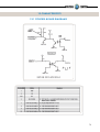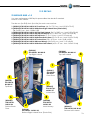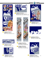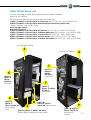
1
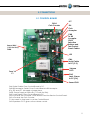
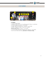
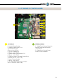
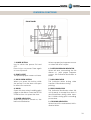
NEW GENERATION V1.0-V2.0
EVO Software
EUR-USA v8.0
America:
Digital Centre America, Inc.
14271 SW 120th Street Unit #109
USA, Miami, FL 33186
Sales:
Ph: +1.305.387.5005
[email protected]
Europe:
Digital Centre
Pol. Ind. Sant Isidre
C/ Puigmal, 20-22 St. Fruitós
08272, BARCELONA. Spain
Ph: +34.938.748.158
[email protected]
Tech Support:
Ph: +1.305.387.5115
[email protected]
www.digital-centre.com
2
Copyright and Trademarks
This manual contains materials protected under International copyright Laws. All
rights reserved. No part of this manual may be reproduced, transmitted or transcribed without the express written permission of the manufacturer and author of this
manual.
The information of the products in this manual is subject to change without prior notice and does not represent a commitment on the part of the vendor. Who assumes
no liability or responsibility for any errors that appear in this manual.
3
CONTENTS
1. Safety Instructions----------------------------------------------------------------------6-7
2. Specifications------------------------------------------------------------------------------8
3.Unpacking· Installation------------------------ -------------------------------------9-10
4.Features-------------------------------------------------------------------------------10
4.1 Service Control Panel-------------------------------------------------10
4.2 Power Switch------------------------------------------------------------10
5. Connections---------------------------------------------------------------------------11-16
5.1 Control Board-----------------------------------------------------------11
5.2 PC wiring-----------------------------------------------------------------12
5.3 PC wiring to Control Board---------------------------------------13
5.4 Printer----------------------------------------------------------------------14
5.5 General--------------------------------------------------------------------15
5.6 Monitor--------------------------------------------------------------------16
6.Printer----------------------------------------------------------------------------------17-28
7.Playing--------------------------------------------------------------------------29-34
8.Customized----------------------------------------------------------------------35-48
8.1 Structure------------------------------------------------------------------35
8.2 Logo-------------------------------------------------------------------36-37
8.3 Welcome /Bye-----------------------------------------------------38-39
8.4 Text---------------------------------------------------------------------40-41
8.5 Music----------------------------------------------------------------------42
8.6 Frames----------------------------------------------------------------43-48
9.Uploading------------------------------------------------------------------------------49
10.Setup menu-------------------------------------------------------------------------50-55
10.1 Switch ON/OFF product--------------------------------------------51
10.2 Products & Price--------------------------------------------------51-53
10.3 Rentals---------------------------------------------------------------------54
10.4 Customize--------------------------------------------------------------54
10.5 Options------------------------------------------------------------------55
10.6 Camera-----------------------------------------------------------------55
11.Troubleshooting----------------------------------------------------------------56-72
11.1 Uploading The Logo--------------------------------------------59-60
11.2 Hard Drive---------------------------------------------------------61-64
11.3 Boot DVD--------------------------------------------------------------65
11.4 Camera Error---------------------------------------------------------66
11.5 Blue Screen------------------------------------------------------------67
4
11.6 Pink screen-------------------------------------------------------------68
11.7 Black screen-----------------------------------------------------------69
11.8 Printer Error--------------------------------------------------------70-71
11.9 No signal---------------------------------------------------------------72
11.10 Control Board Error------------------------------------------------72
12.Characteristics-----------------------------------------------------------------73-79
12.1 Control Board Diagrams------------------------------------------73
12.2 Decals -------------------------------------------------------------74-77
12.3 Spare Diagrams--------------------------------------------------78-79
12.4 Part List--------------------------------------------------------------80-85
12.4.1 NG Blue v1.0/v2.0 Sony-Buttons-----------------80-82
12.4.2 NG Black v1.0/v2.0 Sony-Buttons-----------------83-85
13. Notes------------------------------------------------------------------------------------------86
5
1-Safety INSTRUCTIONS
The following directions must be followed carefully for safe use, to prevent personal
injuries, and damage to the equipment.
Please read this entire manual before initial use and store it in a convenient location
for on easy access.
WARNING: To ensure safe operation, observe specifications, notices and cautions in
this document. Digital Centre Accepts no liability for damage or injuries from improper
use of this product.
WARNING: Prevent electrical shock and equipment damage. Before connecting or
disconnecting cables and/or changing the paper, disconnect power cord from the
A/C outlet.
WARNING: Prevent shock hazard and damage. Only plug the power cord into a
220 volts (110 volts for USA) grounded A/C outlet.
WARNING: Do not touch exposed wires or moving parts such as power supply modules
and the control board. Touching these parts could cause electric shock or other injury,
data loss, and/or printer malfunction.
WARNING: Only use Mitsubishi CK9046(DC) paper / ink ribbon set in the printer. Use of
other paper / ink ribbon will cause software malfunction, poor image quality, and/or
printer damage.
WARNING: Do not touch the thermal print head, or head area of the printer. The print
head operates at an extremely hot temperature. Touching it might cause burns or
other injury.
WARNING: Follow the directions in the Mitsubishi manual when cleaning the printhead.
Do not use cotton, wool or other fabric swabs. The lint left behind poses a fire hazard.
NOTICE: Read additional Warnings in Mitsubishi Printer Manual.
WARNING: The printers are not interchangeable.
Danger: Tipping Hazard! Photo Booth may pose danger to small children and/or pets.
Unplug the power cord from the A/C outlet immediately if the Photo Booth tips over.
WARNING: Use only original parts from Digital Centre.
Use only original parts for your photo booth from Digital Centre. Non original parts
may compromise the use of the photo booth and may create a malfunction and
cause serious damage. Using different components, changing wiring, or altering the
photo booth in any fashion will void the warranty.
Digital Centre is unable to assist any customer that has changed, modified, or altered
the photo booth using non original parts. We cannot provide a guarantee or service
for products that are not original parts from Digital Centre.
6
Danger: Power Off the Photo Booth immediately if any of the following occurs:
· Smoke
· Unusual Odor
· Unusual Noise
· Water or other Liquids spill inside the Photo Booth
· Physical Damage
Danger: Do not place or store the Photo Booth in wet or extremely humid areas, in direct
sunlight, near an open flame or heater, and/or swimming pools. Avoid Condensation.
Danger: Operate the Photo Booth in locations with ambient temperatures of 5°C – 40°C
(41°F – 104°F)
Danger: Install the Photo Booth on a flat, even and, clean surface.
Danger: Repairs should only be made by qualified technicians.
WARNING: Indoor Use Only
MAINTENANCE: Cleaning: Use only a clean, dry, soft cloth. If necessary use a damp cloth
and/or neutral detergent. Do not use window cleaner or any other alkaline cleaners.
7
2-Specifications
NEW GENERATION V1.0
Power Supply: AC 220V 50/60 Hz
(110V for USA)
Power Consumption: 260W
Dimensions:
Width= 73 cm - Inch 29
Length= 94,5 cm - Inch 37
Height= 194 cm - Inch 77
Weight = 160 kg / 352 lbs.
Nominal fuse rating= 6 Amps
Monitor: LCD Color Monitor 17”
Printer: Mitsubishi CP9550 Dye
Sublimation Photo Printer
NEW GENERATION V2.0
Power Supply: AC 220V 50/60 Hz
(110V for USA)
Power Consumption: 260W
Dimensions:
Width= 73 cm - Inch 29
Length= 94,5 cm - Inch 37
Height= 198 cm - Inch 77.2
Weight = 160 kg / 352 lbs.
Nominal fuse rating= 6 Amps
Monitor: LCD Color Monitor 17”
Printer: Mitsubishi CP9550 Dye
Sublimation Photo Printer
Specifications may change at any time without prior notice.
8
3-Unpacking · Installation
These are the accessories included with your new Digital Centre Photo Booth:
Manual
Power Cord
Keys
Boot DVD
Warning: Movement of the photo booth requires assistance from two or more people.
· Unwrap and remove all packaging materials. Remove screws and metal holding plates
that attach the Photo Booth to the skid.
· All major components of the Photo Booth are located under the seat. Access to the components is through the lower rear service door.
· Access to the printer and the USB port of the computer is on the right side of the seat.
Unlock and open this side service door and then remove the protective polystyrene foam
block before first use.
· The keys for the service door, service panel, manuals, and power cord are located in the
picture chute on the right side of the Photo Booth.
· Inspect the wiring harnesses for disconnected plugs.
9
Adjust the height of the four metal legs once the final location for
the booth has been established.
The metal legs are underneath
the cabin next to the wheels.
Plug the power cord into the
socket underneath the Photo
Booth. Slide the power switch to
the “ON” position.
4-FEATURES
4.1 Service Control Panel
1
2
3
4
5
1. Coin Counter
2. Credit (Red Button)
3. Accounts (Black Button): It prints detailed vending
report including number of prints available.
4. Menu (Yellow Button): It enters setup Menu and allows options such as pricing, logos, camera adjustments, and features to be changed.
5. Volume Control lever.
4.2 Power Switch
The Power Switch is located underneath the cabin.
It contains a Fuse and a power cord socket.
10
5-connections
5.1 CONTROL BOARD
CN14
Coin Counter
JP7
JP4
Coin
Acceptor
Power 230V
(115V for USA)
CNT8
CN8
To Bill
Acceptor
CN10
Selection
Buttons and
Test Control
Panel Cables
JP5
CN6
Serial Cable
to PC (P.2)
Fuse 1A
F1
Volume
POT1
CN5
Jack Stereo
to PC (P.6)
Sound CN3
CN6. Serial Cable. From Control Board to PC.
CN8. Bill Acceptor Cable. From Control Board to Bill Acceptor.
JP4, JP5 and JP7. We need a jumper here.
CNT8. Power Supply at 230 volts (115 volts for USA).
CN5. Jack Stereo. From Control Board to PC
CN10 Controls the Customer’s Push Buttons and the Service Control Panel.
CN14 Controls the Coin Counter.
F1. We need 1A fuse here to run the Control Board.
CN3. Speakers. POT1 gives us the volume control.
11
5.2 PC WIRING
P.7
P.8
P.2 P.3 P.4 P.5 P.6
P.1
PC WIRING
P.1 Main Power Cable.
P.2 Serial Cable From PC to Control Board M/F. (56 cm - Inch 22,04)
P.3 VGA Cable M/M (180 cm - Inch 70,87)
P.4 USB Cable From Printer to PC. (180 cm - Inch 70,87)
P.5 USB to Serial Converter. Zoom Sony Camera
(20 cm - Inch 7,87)
P.6 Jack Stereo Cable. (180 cm - Inch 70,87)
P.7 S-VHS Cable M/M From Camera to PC. (250 cm - Inch 99,42)
P.8 115 volts - 230 volts Switch. (Pre-Set to 115 Volts for USA)
12
5.3 PC WIRING to control board
D
P.1
P.2
P.3
P.1
P.4
P.5
P.6
P.7
C
PC WIRING
GENERAL WIRING
P.1 Main Power Cable.
P.2 Serial Cable From PC to
Control Board M/F.
(56 cm - Inch 22,04)
P.3 VGA Cable M/M.
(180 cm - Inch 70,87)
P.4 USB Cable From Printer to PC.
(180 cm - Inch 70,87)
P.5 USB to Serial Converter. Zoom Sony
Camera (20 cm - Inch 7,87)
P.6 Jack Stereo Cable.
(180 cm - Inch 70,87)
P.7 S-VHS Cable M/M From Camera
to PC. (250 cm - Inch 99,42)
C. Cable From Control Board to
Service Panel & Push Buttons
+ 2 Speakers.
D. Cable from Control Board
to Bill or Coin Validator.
13
5.4 PRINTER
P.4
P.1
PRINTER WIRING
P.1 Main Power Cable.
P.4 USB Cable From Printer
to PC AM/BM.
(180 cm - Inch 70,87)
14
5.5 general
1
A
8
9
P.1
5
4
COMPONENTS
7
6
3
PC WIRING
P.1 Main Power
1. Printer Mitsubishi CP9550DW-DC.
Cable.
2. PC 5.
3. PC-5 Holder. (RAW METAL)
4. Control Board .
5. Wood Printer Base. NG (RAW)
6. Wood PC Base. NG (RAW)
7. Transformer Socket Plastic Base.(WHITE)
8. Security Disconnection Button On-Off-On.
9. Transformer 2A 12V
2
GENERAL WIRING
A. Service Control Panel
Model 1
15
5.6 monitor
P.7
P.5 15
20
E
P.1
14
16
18
12
22
19
B
13
17
23
21
24
11
25
P.3
P.1 P.7
COMPONENTS
11. Bottom Holders for Monitor.
NG (RAW METAL)
12. Metal holder for Camera NG.
13. Top Holders for Monitor. NG
(RAW METAL)
14. Camera Glass Metal Holder.
(RAW METAL)
15. Sony Camera FCB.
16. Speakers 8 Ohm 5W.
(10 cm - Inch 3,94)
17. LCD Monitor 17” ACER.
18. Double Push Buttons Ok/Cancel. NG
19. Double Push Buttons Right/Left. NG
20. Ballast 13W
21. Lateral Light Diffuser Holder. (RAW METAL)
22. Right / Left Light Plastic Diffuser.
(WHITE) (18x4x0,3 cm - Inch 7,09x1,57x0,12)
23. Light Bulbs 9 W/865
24. Lamp Holder 9W
25. Monitor Holder NG v1.0 (RAW METAL)
C
PC WIRING
P.1 Main Power
Cable.
P.3 VGA Cable M/M
(180 cm - Inch 70,87)
P.5 RS-232 Serial Cable
From Camera Sony FCB.
(20 cm - Inch 7,87)
P.7 S-VHS Cable M/M From
Camera to PC.
(250 cm - Inch 99,42)
GENERAL WIRING
B. 12V Extension M/F
Cable From Camera To 12V
Transformer (235 cm - Inch 92,51)
C. Cable From Control
Board to Service Panel & Push
Buttons +2 Speakers
E. RS-232 Extension M/F Serial
Cable From Camera to PC.
(300 cm - Inch 118,11)
16
6-PRINTER
WARNING: The printers are not interchangeable
· Protective Measures
This printer is designed to operate with Photo Booth systems. Do not remove any
inside components. Do not try to repair or manipulate it. Before printing, install an
Ink sheet and paper.
Never insert any object into the unit.
Foreign objects of any kind inserted into this unit is safety hazard and can cause
extensive damage.
Do not place anything on the digital color printer.
Heavy objects placed on the digital color printer can cause damage or obstruct
proper ventilation.
Do not remove the cabinet.
Touching internal parts is dangerous, and may lead to malfunction. Contact the
sales dealer to carry out internal checks and adjustments. Before opening the
cover for eliminating a jammed paper, etc ... , be sure to disconnect the power
cord plug.
When transporting the unit.
When transporting the unit, remove the ink sheet and print paper from the unit.
Be careful around print paper exit slot.
Do not insert your hand or any material into the paper exit slot during printing.
Do not touch the cutter blade inside the paper exit slot. Otherwise, your finger will
be injured.
Do not touch the thermal head.
Do not touch the thermal head (located inside the unit).
The thermal head is heated to a high temperature. This may cause injury.
Ink sheet and paper print supply.
Use only the ink sheet and paper supplied by Digital Centre, otherwise the Photo
Booth system will not work, and Digital Centre does not assume any responsibility
for damages or injuries.
17
Features & Functions
FRONT PANEL
1· POWER BUTTON
Use to switch the power ON and
OFF.
Press to turn on power. Press again
to turn off power.
When a paper jam happens occurs
or when the door is open.
2· PRINT OUTLET
The printed paper comes out here.
6· PAPER/INK RIBBON INDICATOR
When an error concerning the ink
ribbon or print paper happens
occurs, this indicator illuminates or
blinks
3· DOOR OPEN BUTTON
When you press this button while
the power is on,the door will open
in about five seconds.
7· DATA INDICATOR
This indicator blinks during data
transfer. It illuminates during
printing.
4· DOOR
Open this door when installing print
paper or ink ribbon. Press the DOOR
OPEN button 4 to open the door.
8· READY INDICATOR
This indicator illuminates when this
unit is ready to accept the data. It
also illuminates during data transfer. It blinks during print canceling
procedure.
5· POWER INDICATOR
When the power is turned on, the
indicator illuminates.
9· COOLING INDICATOR
When the unit is overheated, this indicator blinks.
18
10· CANCEL BUTTON
Press this button for a little over 1
se¬cond to cancel continuous printing. After the button is pressed the
printing process is canceled.
11· FEED & CUT BUTTON
Hold down this button for a little over
1 second and the printer pa¬per is
fed and cut.
SIDE AND REAR PANEL
1· USB TERMINAL
Use to connect the USB cable.
2· DIP SWITCHES
Never touch it.
3· HANDLE FOR TRANSPORTING
When transporting this unit, hold this
handle and the lower front part of this
unit.
4· POWER SOCKET (AC LINE)
Use to connect the provided power
cord. Insert the cord firmly.
Before Operation
BEFORE PRINTING
1 Install the print paper to this unit. (See below.)
2 Install the ink ribbon to this unit.
19
INSTALLATION OF PRINT PAPER
· SPACERS
The spacers are attached to the paper flanges. The spacers are necessary, for reasons see the Quick Setup Guide. Re¬move the cushions put between the paper flange
and spacer when using them.
How to attach and remove the spacers
1. Turn the spacer until the latches are unlocked.
2. Remove the spacer with the paper flange’s stoppers
retracted.
When you use the print paper with the correct spacers
that have to be used, attach the spacers to the paper
flanges by reversing the removal procedure as shown on
right.
1
Attach the supplied paper flanges to both sides of the print
paper. When you pinch the latches on the paper flange,
the stoppers retract into the shaft. Attach the flanges to
the print paper with the stoppers retracted. Make sure
that the flanges are attached to the print paper securely,
and release the latches.
NOTE
· Be careful not to pinch your fingers.
· Do not remove the sticker on the print paper yet.
· Do not slack the paper. Any slack in the print pa- per may degrade the print quality.
CAUTION
· When placing the print paper, remove one flange and keep the print paper upright on its side with no flange.
· When you put the print paper sideways, it may roll and fall. This may cause injury.
NOTE
· Do not touch the thermal head.
· Fingerprints or dust on the thermal head will degrade
the print quality.
20
Before Operation
2
Press the POWER button to
turn on the power.
3
Press the DOOR OPEN button
to open the door.
Take the ink cassette in the
printer out.
4
Install the print paper into the
unit. Make sure to install the
print paper firmly.
Thermal head (Inside)
Direction of paper
insertion
NOTE
Install the print paper into the unit slowly. If it is dropped along the ditches, the unit or
accessories may be damaged.
CAUTION
Do not touch the thermal head right after printing because it is extremely hot.
Otherwise you may get burned or injured.
NOTE
Note that the thermal head is quite sensitive to static electricity. When you touch the
thermal head while carrying static electricity on your body, the thermal head may
be damaged.
21
Before Operation
Print paper
Roller
Black cover
5
Remove the sticker, insert the print paper between the rollers as shown above, and feed
the print paper until it reaches the black cover.
Remove the sticker before inserting the print paper between rollers. Make sure to insert
the paper straight.
NOTE
· Keep the roller clean.
· Dirt on the roller may degrade the print quality.
NOTE
· When taking the print paper out, pull it up toward you.
· Make sure to turn on the power before replacing the print paper.
· Make sure to eliminate any slack from the print paper. If you carry out the following
steps without eliminating the slack, the print paper may be damaged.
2
INSTALLATION OF INK RIBBON
INSTALLING THE INK RIBBON
After installing the print paper, load the ink ribbon in the ink cassette.
Then install the ink cassette into this unit.
NOTE
· Place the ink cassette on a flat surface, when loading the ink ribbon.
· Select a place that is free of dust when loading the ink ribbon. Dust or dirt settling on the ink ribbon results in poor print quality.
· Make sure that the shafts of the ink ribbon fit into the ink cassette firmly.
22
INSTALLING THE INK CASSETTE
1· Place the ink cassette containing the ink ribbon in the position as shown above.
Place the ink cassette on the print paper with the shaft (thicker one) around which the
ink ribbon is wound located to the front. Align the arrows marked on the sides of ink
cassette with those on the unit. Place the rear of the ink cassette along the guides that are
provided inside the unit.
Make sure to set the ink ribbon roller to the ditches firmly. Turn the ivory roller to eliminate
any slack.
Thermal head (Inside)
Arrows
Guides
23
Before Operation
2· Push the ink cassette toward the back of the unit.
Hold the handle of the ink cassette and push it straight toward the back of the unit.
Then raise it until you hear a click to secure it in the ink cassette holder.
NOTE
If the ink ribbon is used up, repeat the steps 1 and 2 to replace the print paper and the
ink ribbon.
Thermal head (Inside)
3· Push the center of the door to close.
The print paper setting is initialized two minutes after you close the door.
When the auto feed & cut mode has been selected, the FEED & CUT procedure is repeated
three times after you close the door. When the print paper with the post card printing on its
reverse side is installed, the FEED & CUT procedure is repeated five times.
NOTE
· When closing the door, push it until a click is heard.
· If the PAPER/INK RIBBON indicator illuminates when the door is closed, the print paper may have not been installed correctly.
In this case, open the door to make sure that the print paper has been installed
correctly. Then close the door again.
· On the auto feed & cut mode, when the print paper is installed more than three times,
the print paper may be used up earlier than the ink ribbon.
24
When the manual & cut mode has been selected
When the manual feed & cut mode has been selected, hold down the FEED & CUT
button for 1 second or longer. Repeat the manual feed & cut three times. When the print
paper with the postcard printing on its reverse side is installed, repeat this procedure five
times.
To select the auto feed & cut mode, see “Setting of the DIP switches”
Installation of the print paper and the ink ribbon is completed.
NOTE
· Make sure to replace the print paper and the ink ribbon at the same time.
· When replacing them, throw away the paper chips in the paper strip bin.
Error Messages & Countermeasures
OVERCOMING PAPER JAMS
1· Press the DOOR OPEN button to open the door.
Make sure that the power is turned on before
opening the door.
If the door does not open, turn off the power and
turn it on again.
Then press the DOOR OPEN button again
25
2· Remove the ink cassette.
Push down the ink cassette as
shown by the arrow 1 and pull it
out.
3· Take out the print paper.
When taking the print paper
out, pull it up toward you.
4· Cut off the defective part of the print paper
with scissors.
NOTE
Make sure to cut off the printed part of the print
paper. Failure to do this may result in the ink ribbon
sticking to the print paper and being torn.
5· Install the print paper and the ink cassette with
the ink ribbon.
6· Push the center of the door to close.
The print paper setting is initialized two minutes after you close the door.
When the auto feed & cut mode has been selected, the FEED & CUT procedure is repeated three
times after you close the door. When the print paper with the postcard printing on its reverse side is
installed, the FEED & CUT procedure is repeated
five times.
26
When the manual feed & cut mode has been
selected, hold down the FEED & CUT button for 1
second or longer. Repeat the manual feed & cut
three times. When the print paper with the
postcard printing on its reverse side is installed,
repeat this procedure five times.
For how to select the auto feed & cut mode, see
“Setting of the DIP switches”
Cleaning
Cleaning as indicated below will help maintain stable
printer operation and extend the printer’s life.
Preparations:
Alcohol (isopropyl alcohol)
Tissue paper (Fold in half about four times, and use the
folded side to clean.)
Other : Cleaner pen (option)*, Cleaning ribbon (option)*
* Please ask the dealer about options.
PREPARATIONS FOR CLEANING
1 Press the POWER button to turn on the power.
2 Press the DOOR OPEN button to open the door.
3 Remove the ink cassette.
4 Take out the print paper.
5 Press the POWER button to turn off the power.
Make sure to turn off the power before cleaning.
THERMAL HEAD CLEANING
Clean the heat-generating part below the thermal head.
Wipe the head cleaning part carefully with tissue paper
dampened with a small amount of alcohol.
NOTE
· Do not damage the thermal head.
· When the poor print quality is not corrected even
if the head has been cleaned, replacement of the
thermal head may be required. Contact your
dealer.
27
CAUTION
· Thermal head is hot right after printing. Wait until the head is cold
before cleaning the thermal head.
NOTE
· The thermal head may be damaged if you touch it
while static electricity builds up on your body.
PAPER FLANGE CLEANING
Clean the parts that contact the print paper sides as shown
above.Wipe the parts carefully with tissue paper dampened
with a small amount of alcohol.
28
7-playing
Demo Mode
DEMONSTRATION
When there are no vends, the machine
enters in Demo Mode. Photo samples are
displayed. Once money is inserted, you
are taken to the credit screen.
PRODUCT SCREEN
PRODUCT SCREEN
You can choose 6 different products.
29
Photo ID
Color and Black & White
When the instructions conclude, you
have the option to choose “Color” or
“Back & White” pictures.
SHOTS
4 Shots are taken.
(3 shots if you activate the logo)
PRINTING
The pictures are shown on the screen
while strips are printing.
30
Hairstyles
SELECT DESIRED LOOK
You can choose different hairstyle options
SHOTS
Align your face with the circle
on the screen.
Not bigger not smaller!
PRINTING
The pictures are shown on the screen
while the strips are printing.
31
Hats
FRAMES SELECTION
Different hats options you may choose
from.
SHOTS
Align your face with the circle
on the screen.
Not bigger not smaller!
PRINTING
The pictures are shown on the screen
while the strips are printing.
32
Street Art
SHOOTS
3 Shots are taken,
Street Art Selection
Select one design.
PRINTING
The Street Art is shown on the screen
while the picture is printing.
33
Get Framed
FRAMES SELECTION
Different frame options you may choose
from.
SHOTS
4 Shots are taken.
PRINTING
The pictures are shown on the screen
while the strips are printing.
34
8-Customized
This procedure will allow you to customize your Photo Booth with custom logos,
welcome,..., and other ones.
8.1 structure
Logo
Welcome
A
Bye
USB stick
PhotoIdUpload
You must create
this folder
Text
BGmusic
Frames
1a,1b,1c,1d
2a,2b,2c,2d
...
1· Necessary Materials:
USB stick with 2 GB of available space
We recommend using a USB stick with a led indicator
USB STICK Off
(LED desactivated)
USB STICK On
(LED activated)
USB STICK Blinking
(LED activated)
35
8.2 logo
Logo
1
Welcome
A
Bye
USB stick
PhotoIdUpload
You must create
this folder
Text
BGmusic
Frames
1a,1b,1c,1d
2a,2b,2c,2d
...
DIRECTIONS FOR UPLOADING THE LOGO
USB stick
PhotoIdUpload
*PhotoIdUpload
Logo
You must create
this folder
ld means ID not LD
1· Necessary Materials:
USB Stick with 2 GB of available space
We recommend using a USB Stick with a led indicator
36
2-Create a folder on the USB stick and name it PhotoIdUpload
3-Insert the logo that you want to use in the folder PhotoIdUpload
4-Connect the USB Stick to the Photo Booth
5-Go to Setup Menu (important) and confirm that logo is activated
USB stick
PhotoIdUpload
Logo
You must create
this folder
Height: 600 pixels
Width: 800 pixels
Sample Logo
Logo Characteristics:
Name: Logo
Size: width: 800 pixels
height: 600 pixels
Resolution: 300dpi
We recommend
300dpi, but it will also
work with less resolution.
Format: JPG
Not working? Please refer to section 11.1 for assistance
UPLOADING ( See section 9)
SETUP MENU ( See section 10)
37
8.3 WELCOME/BYE
Logo
Welcome
2
A
USB stick
Bye
PhotoIdUpload
You must create
this folder
Text
BGmusic
Frames
1a,1b,1c,1d
2a,2b,2c,2d
...
DIRECTIONS FOR UPLOADING WELCOME/BYE
Welcome
USB stick
PhotoIdUpload
You must create
this folder
Bye
*PhotoIdUpload
ld means ID not LD
38
Welcome message
Welcome
PhotoIdUpload
Sample Welcome
You must create
this folder
Specifications:
Name: Welcome
Size: width: 800 pixels
height: 600 pixels
Resolution: 72dpi
Format: JPG
Bye message
Bye
PhotoIdUpload
You must create
this folder
Sample bye
Specifications:
Name: bye
Size: width: 800 pixels
height: 600 pixels
Resolution: 72dpi
Format: JPG
39
8.4 text
Logo
Welcome
A
Bye
USB stick
PhotoIdUpload
You must create
this folder
3
Text
BGmusic
Frames
1a,1b,1c,1d
2a,2b,2c,2d
...
DIRECTIONS FOR UPLOADING TEXT
USB stick
Text
PhotoIdUpload
*PhotoIdUpload
ld means ID not LD
You must create
this folder
Name: Text
Format: txt
40
All text in this file is printed vertically on the
left side of the photostrips.
Rent your Booth (888). 888. 888
Sample: Rent your Booth (888). 888. 888
UPLOADING ( See section 9)
SETUP MENU ( See section 10)
41
8.5 music
Logo
Welcome
A
Bye
USB stick
PhotoIdUpload
You must creat
this folder
Text
BGmusic
Frames
4
1a,1b,1c,1d
2a,2b,2c,2d
...
DIRECTIONS FOR UPLOADING MUSIC
USB stick
BGmusic
PhotoIdUpload
*PhotoIdUpload
ld means ID not LD
You must create
this folder
Name: BGmusic
Format: mp3
PhotoBooth, the only
You can Upload any song to the
thing you need to do is change the song’s name to
“BGmusic”and save the file into the “PhotoIdUpload”
folder
UPLOADING ( See section 9)
SETUP MENU ( See section 10)
42
8.6 frames
Logo
Welcome
A
USB stick
PhotoIdUpload
You must create
this folder
Bye
Text
5
BGmusic
Frames
1a,1b,1c,1d
2a,2b,2c,2d
...
FRAMES
To create a new framework we
will create a file with the following
characteristics.
43
To create a new framework we
will create a file with the following
characteristics.
SAMPLE
Name: Check structure name
Size: width: 800 pixels
height: 600 pixels
Resolution: 72dpi
Format: PNG
It’s very important to save the file
of the frames only in PNG format.
Create your own customized
frame. Inside of the blank area is
where the camera will capture
the image, and your customized
frame will surround the image.
DIRECTIONS FOR UPLOADING FRAMES
USB stick
Frames
PhotoIdUpload
*PhotoIdUpload
1a,1b,1c,1d
2a,2b,2c,2d
...
You must create
this folder
ld means ID not LD
44
Frames
PhotoIdUpload
You must create
this folder
1a,1b,1c,1d
2a,2b,2c,2d
...
1
Screen 1 (group 1)
1a
1b
1c
Screen1
1
1d
2
3
1a
1b
2a
2b
3a
3b
1c
1d
2c
2d
3c
3d
4
4a
4c
5
4b
4d
6
5a
5b
6a
6b
5c
5d
6c
6d
45
Screen2
7
8
9
7a
7b
8a
8b
9a
9b
7c
7d
8c
8d
9c
9d
11
10
12
10a
10b
11a
11b
12a
12b
10c
10d
11c
11d
12c
12d
Screen3
14
13
15
13a
13b
14a
14b
15a
15b
13c
13d
14c
14d
15c
15d
17
16
18
16a
16b
17a
17b
18a
18b
16c
16d
17c
17d
18c
18d
46
Sample
If you want to customize the group Nº1 (from screen 1) follow this structure.
Frames
PhotoIdUpload
1a,1b,1c,1d
1
You must create
this folder
Screen 1 (group 1)
1a
1b
1c
1d
1
Frames
PhotoIdUpload
1a,1b,1c,1d
Screen 1 (group 1)
1a
1b
You must create
this folder
1c
1d
47
Sample
If you want to customize the groups Nº1,2 & 3 follow this structure.
1
Frames
PhotoIdUpload
1a,1b,1c,1d
Screen 1 (group 1)
1a
1b
You must create
this folder
1c
2
Frames
PhotoIdUpload
2a,2b,2c,2d
You must create
this folder
PhotoIdUpload
3a,3b,3c,3d
1d
Screen 1 (group 2)
2a
2b
2c
2d
3
Frames
Screen 1 (group 3)
3a
3b
You must create
this folder
3c
3d
UPLOADING ( See section 9)
SETUP MENU ( See section 10)
48
9-uploading
1-Switch ON the Photo booth
2-Open the Photo slot door*
PRINTER
PC
(HP C2D)
USB
stick
3-Insert the USB Stick to the PC (HP
C2D) (the usb connection is on the
left side of the PC)
4-Open the back door of
your photobooth.
5-Press the yellow button from the
Service Control Panel, to access the
Setup Menu.
* You will need 1314 keys (included
on your photobooth)
6-Press the yellow button for the menu
SERVICE
CONTROL
PANEL
49
10-SETUP menu
The setup menu is very useful for the owner of the Photo Booth. You can configure the
Photo Booth depending on what kind of service you want to offer to your costumers.
You can control the timer, check the prices, adjust the camera settings or consult the
accounting functions. To go to the setup menu while the Photo Booth is in Demo Mode,
press the yellow button (Menu) from the Service Control Panel inside the Photo Booth.
Once at the setup menu, use the buttons of the user control panel to be able to operate
it. Use the green OK button to move inside the menu and the yellow arrows to go to the
submenu and the red CANCEL button to leave the menu.
SETUP MENU SCREENSHOOTS
CONFIGURATION
The configurable parameters are
divided in 5 groups:
· Products & Prices
· Rentals
· Customize
· Options
· Camera
50
10.1 SWITCH ON/OFF PRODUCT
Displayed only activated
products.
10.2 PRODUCTS & PRICES
You can turn ON the option of Extra
copies, extra product and/or
also set the price.
51
10.2 PRODUCTS & PRICES
EXTRA COPIES
If you activate this option after
each item it displays if you want
more copies.
10.2 PRODUCTS & PRICES
EXTRA COPIES
Inserts $1 for more copies.
52
10.2 PRODUCTS & PRICES
EXTRA COPIES
When you insert the money,
it prints 2 more sets.
10.2 PRODUCTS & PRICES
EXTRA PRODUCT
If you activate this option.
You can make a copy with
a new product.
53
10.3 RENTALS
Free Play: YES( ) NO ( )
Timer: YES ( ) NO ( )
Start: 2011-X-X (Day)- XX:XX(Hour)
Finish: 2011-X-X (Day)-XX:XX(Hour)
Token: YES ( ) NO ( )
10.4 CUSTOMIZE
To set up the Logo, the Welcome
and Bye screens, the Fun Frames,
to Print date and Print text.
54
10.5 OPTIONS
It defines the parameters for some
available features:
Cabine Color: Select the color of
your Photo Booth
Current Time: 2011-X-X (Date)
XX:XX(Hour)
Demo Music: YES ( ) NO ( )
10.6 CAMERA
In the submenu CAMERA, the
owner can set the camera zoom
position and brightness.
55
11-Troubleshooting
· GENERAL PROBLEMS
Problem
The unit switch is ON, but it
does not turn on
Causes
The unit is not plugged in.
The voltage is incorrect.
Overload: the fuse over the electric
socket has been blown.
Solutions
Check if the unit is correctly
connected to the electric ground.
Check if the electric ground is
receiving electricity.
Be sure that the voltage is correct.
Change the fuse.
Problem
The fluorescent does not turn on.
Causes
The fluorescent lights have been blown.
The transformer has been blown.
Solutions
Replace the fluorescent lights
(see above).
Replace the transformer
· Monitor’s Problems
Problem
The monitor image looks darker or
lighter
Problem
The monitor image moves up and
down
Causes
The monitor is not adjusted correctly.
Causes
The monitor is not adjusted correctly.
Solutions
Readjust the monitor.
Solutions
Readjust the monitor.
56
· Sound Problems
Problem
The sound does not work
Causes
The volume is not correct.
The configuration menu has the sound set to OFF.
Solutions
Adjust the volume with the control placed below the test,
free-play and start buttons.
Change the sound configuration from the test menu
(black button).
· PRINTER Problems
Problem
The printer does not print any
photos
Causes
The printer is disconnected.
The printer is out of ink or paper.
The paper or the ink sheet was not
properly installed.
Incorrect paper.
USB/ LPT Dallas Chip position is
incorrect.
Solutions
Switch on the printer.
Call the person in charge
Correctly place the paper
and the ink.
Use only CK9550-DC type paper.
· pc Problems
Problem
Install a brand new Control Board
with Atmel and jumpers.
Causes
This problem is due a hardware
malfunction.
Check the green Capture Board, as
it is probably out or half way in.
Problem
The printer does not switch on
Causes
The printer is disconnected.
The printer does not receive electric
supply.
Solutions
Connect the printer.
Be sure that the cable is correctly
connected.
Problem
It prints one or more white lines
Causes
Thermal head is broken.
Solutions
Replace thermal head.
Solutions
Turn OFF the PC.
Take out the Capture Board. And put
it again (all the way in).
Screw hard and check again that it is
all the way in, and did not move little
out during screwing.
Turn ON the PB and check it.
57
· WARNING
· If you have any doubts or any problems with the unit and the way it is performing,
call a technician to solve the problem.
· Devices such as the printer or the camera are very fragile and must be used carefully.
Printer
Cleaning.
Check configuration.
Monthly
Glasses
Cleaning.
Weekly.
Control Panel
Check the functioning of
all buttons
Monthly
Lights
Check the functioning
of all the lights and the
fluorescent light.
Monthly
Sound
Check the sound. Monthly
Coin Acceptor
Bill Acceptor
Clean and check the
correct functioning
Annually
Interior
Exterior
Cleaning Cleaning
Annually
Weekly
58
11.1 UPLOADING THE LOGO
Problems uploading the logo:
Possible causes:
1-USB STICK is damaged
2-The logo specifications/characteristics are not correct
1-USB is damaged
· Let’s make a test to see if it works at the computer.
· Plug the USB STICK at the front of the PC (HP C2D), and go to Set Up Menu.
Then exit the Menu.
· Take a picture by choosing the product you want.
· After the game, Remove the USB STICK.
· Plug the USB STICK in your PC or LapTop.
· Check if the USB STICK contents the PhotoIdDownload folder.
· It should be 2 folders into the PhotoIdDownload and your picture should be there.
· If your picture is not there, the USB STICK is not working properly.
Myphotocode
USB stick
PhotoIdDownload
Shots
It’s recommended to use a USB Stick with LED and 2GB of space.
USB STICK Off
(LED desactivated)
USB STICK On
(LED activated)
USB STICK Blinking
(LED activated)
59
2-The logo specifications/characteristics are not correct
· Plug the USB Stick in your PC or Laptop.
· Locate the logo, Placed on the logo and click the right button on
your computer mouse to open properties.
· The properties should be as follows.
Click the right button
· Check the logo specifications
Logo specifications:
Name: Logo
Size: width: 800 pixels
height: 600 pixels
Resolution: 300dpi
We recommend 300dpi,
but It will also work with
less resolution.
Format: JPG
LOGO
Name: Logo
Name:
NOT LOGO.JPG
If it doesn’t work, consult a professional designer to assist in changing the logo.
Advanced users:
Use the following web site for suggestions; http://www.webresizer.com/
60
11.2 HARD DRIVE
hard drive error
This procedure is to check if the BIOS settings are correct for an Automatic
BOOT-DVD.
WARNING!!! This procedure is very dangerous and could cause a PC
Malfunction. Please read it carefully and follow all steps one by one.
1· Plug in a Keyboard to the PC.
2· Turn ON the PC (or the whole Photo Booth).
3· When the ASRock screen appears, press “F10” several times until the “BIOS
SETUP UTILITY” appears on the screen. If it does not come up, and the
software continues uploading, then go back to the Step 2.
4· With the Keyboard arrows, move up to
the Advanced Menu. And then, move
down, to the “IDE Configuration” and
press Enter.
61
5· Once you are inside the “DEVICE Configuration” please check the following points:
•“Hard disk” should be connected at SATA0
•“CD-ROM” should be connected at SATA1
If everything is OK, press ESC to return the Main menu.
If Hard disk or CD-ROM or Both are not detected, we should check the PC connections.
(Do this work with the PC unplugged from power).Go to step 8
6· Once you are inside the “Boot Order” please check the following points:
•“ATAPI CD-ROM”
•“Hard Drive”
If ATAPI CD-ROM or Hard Drive or Both are not detected, we should check the PC
connections.(Do this work with the PC unplugged from power).Go to step 8
62
9· Unplug the PC from the power.
10· Open the top cover ( there are 2 screws in the top back side of the PC)
11· Check connections as follows:
IF The Hard Disk is IDE + DVD SATA it will be like this:
HARD DISK IDE
POWER
IDE
DVD SATA
POWER
SATA
DVD SATAII_2
63
IF The Hard Disk is SATA + DVD SATA it will be like this:
POWER
SATA
HARD DISK SATA
HARD DISK
SATAII_4
DVD
SATAII_2
POWER
SATA
DVD SATA
12· If all connections are fine (as it appears
in the pictures), then it is possible that the
component, which is not detected at the
“IDE CONFIGURATION” Menu, is physically
damaged. Please contact Digital Centre
for a new part.
64
11.3 BOOt DVD
To Update the Machine or change the software version, please follow these steps:
1· Open the DVD Driver.
2· Insert the “Boot DVD”.
3· Plug Off the Machine.
4· Plug On the Machine after 10 seconds.
5· Wait while the restore program reinstalls the
software (a progress bar appears on the screen).
The time process is about 30 minutes
6· A black screen appears when the process finishes.
7· Extract the DVD disk.
8· Plug Off the Machine.
9· Plug On the Machine after 10 seconds.
(In case that the Restore Program does not start automatically and
shows the message “Extract the dvd” immediately, then go to the
“Run the Restore Program Manually” (At the end of this Manual).
CUSTOMIZED FRAMES:
If you have customized frames and/or logos now is the time to upload.
1· Install the “Customized Frames DVD” into the DVD driver (CD or USB too).
2· Plug Off the Machine.
3· Plug On the Machine after 10 seconds.
4· When the software is working in Demo, then go into the SETUP MENU, by
pressing the Yellow button at the Setup Control Panel. It will read the customized
frames and/or logos automatically before the software start.
5· Be sure to select LOGO=YES and the correct frames and Wait for the Setup Menu
save all changes. (Wait for the “Shut Down Please” message on the screen).
6· When the software runs in Demo again, you can extract the DVD, CD or USB,
and keep it to a safe place.
The NEW FRAMES are now working; you can go to Setup Menu and adjust the
Date at the correct position.
65
11.4 CAMERA error
Problem:
The signal does not reach the PC.
Cause:
· Camera Video S-VHS signal is not arriving to the PC.
· Power from behind the printer is offline
Problem:
If it shows a Camera error but you see your face on the screen that means that the camera is powered correctly and the S-VHS cable is working correctly, but the data harness
is not communicating correctly, so the PC and the camera has no communication.
Cause:
the data harness, between the camera and the PC, is not communicating correctly.
The Harness consist in 3 different cables:
1-The USB adaptor to serial (P.5. connecting the PC)
2-The Camera Serial Cable (E. Connecting the Sony Camera)
3-The Serial Data Cable that connects the USB adaptor (P.5) with the Camera Serial Cable (E). That cable is very long and it is installed underneath the PhotoBooth, and go from
the Camera to the PC.
66
11.5 Blue screen
BLUE SCREEN (BLUE CAMERA IMAGE).
You take a photo, but your face does not appear on the screen.Only appears a BLUE
screen.
Cause:
· Camera Video S-VHS signal is not arriving to the PC.
Check:
· Please check S-VHS cable that connects to the back of the computer.
It must be all the way in.
P.7
P.7 S-VHS Cable M/M
From Camera to PC.
(250 cm - Inch 99,42)
Please check the transformer that is located behind the Printer. That transformer gives12V
to the camera and the Computer area Fans.
Transformer 2A
12v
67
11.6 pink screen
PINK SCREEN (PINK CAMERA IMAGE).
Problem:
You take a photo, but your face does not appear on the screen. Only PINK screen.
Cause:
· Capture Board (inside the PC) is damaged or not correctly connected.
Check:
· Please, open the PC and check that the Capture Board is correctly connected.
· If the board is correctly connected, but still Pink screen, then call Digital Centre.
Capture Board
(inside the PC)
68
11.7 BLACK screen
Problem:
Nothing on the screen, just Black.
Please let’s check some points, step to step:
1· Can you hear any sound or music in the cabinet?
2· The lights are ON?
Lights are ON
Lights are ON
Lights are ON
69
11.8 PRINTER error
POWER
Printer lights ON
The “Please Wait” error is very common. It
looks like as it the PC freezes, but it isn’t. The
problem is that the computer is waiting for
the right components.
When we turn on the Photo Booth, the computer shows the “Please Wait” screen while it
checks the Control Board, the USB adapter
and the Printer. If any of the components are
not ok, the software doesn’t go ON.
READY
So, when we face this problem we have to
check the 3 components. The procedure is
as Follows:
1· Check the Printer lights ON. Should be ON
the following lights “POWER” and “READY”. If
any other light, please fix it and Turn OFF and
ON the Photo Booth.
2· Check the Printer Connections. Power and USB, just 2 wires.
P.4
P.1
P.4 USB Cable From Printer
to PC. (180 cm - Inch 70,87)
P.1 Main Power Cable.
70
3· Check the Control Board Serial Connection. (That is the common problem Point).
(attached 2 pictures: Correct and Error “Please Wait”). This connection is very easy to lose
during transport, or when we work at that area.
4· If all the 3 points are good, then check the Control Board Red LED is ON.
Red LED is ON
5· Check that the USB Adaptor (Camera zoom) is correctly connected at the right USB
plug (bottom right).
USB Adaptor (Camera zoom)
6· Use the Boot-DVD to restore the PC and configure all components again.
Soon or later, all the customers will face this problem, the only way to fix it is by get the
printer ready to print and the Control Board Serial Cable Correctly connected all the way
in. This problem will not disappear by replacing the PC.
71
11.9 NO SIGNAL
Lights are ON
Check if the PC lights are ON.
If the lights are on then it appears that the Photobooth is working but the monitor is not.
Next steps:
When you turn ON the Photobooth, can you see any message on the screen? (ex; manufacturer name, or “NO SIGNAL”)?
If this is the case, the VGA cable is probably unplugged or damaged.
But if nothing appears on the screen (when you turn ON the Photobooth), please check if
there is power to the Monitor. Power cable is probably unplugged from the monitor.
11.10 control board error
The control Board is the green board located behind the PC. It doesn’t mean that the
Control Board is bad, it could mean that the PC could not connect with the Control
Board (because the Serial cable is not correctly connected).
Check following points:
1· Check the Control Board Serial Connection. (That is the common problem Point).
(attached 2 pictures: Correct and Error “Please Wait”). This connection is very easy to
lose during transport, or when we work at that area.
2· If all connections are good, then check that the Control Board Red LED is ON.
Red LED is ON
72
12-CHARACTERISTICS
12.1 CONTROL BOARD Diagrams
73
12.2 DECALS
Standard Blue v1.0
You can use images of 300 dpi to personalize the decals if needed.
Save in a JPG format.
The size cm (for EUR) inch (for USA) for each one must be:
1-(DE2901) STD DECAL. NG BU #1 Front Door (64,5 x 179,5 cm - Inch 25.20 x 70.47)
2-(DE2902) STD DECAL. NG BU #2 Bottom Right Lateral Door (Photo Slot)
(34,5 x 24,5 cm - Inch 13.38 x 9.50)
3-(DE2903) STD DECAL. NG BU #3 Top Right Lateral (24,5 x 128,5 cm - Inch 9.50 x 50.40)
4-(DE2904) STD DECAL. NG BU #4 Top Let Lateral(24,5 x 128,5 cm - Inch 9.50 x 50.40)
5-(DE2905) STD DECAL. NG BU #5 Top Back (71’5 x 118 cm - Inch 27.95 x 46.46)
6-(DE2906) STD DECAL. NG BU #6 Bottom Back Door (59,5 x 50 cm - Inch 23.23 x 19.68)
7-(DE2907) STD DECAL. NG BU #7 Instructions (50 x 16,5 cm - Inch 19.68 x 6.30)
8-(DE2908) STD DECAL. NG BU #8 Insert Money (28,5 x 22 cm - Inch 11.02 x 8.66)
9-(DE2909) STD DECAL. NG BU #9 Bottom Left Lateral (42,5 x 57 cm - Inch 16.54 x 22.44)
3
(DE2903)
STD DECAL. NG BU #3
Top Right Lateral
(DE2904)
STD DECAL. NG BU #4
Top Left Lateral
4
1
(DE2901)
STD DECAL.
NG BU #1
Front Door
5
(DE2905)
STD DECAL.
NG BU #5
Top Back
7
(DE2907)
STD DECAL.
NG BU #7
Instructions
6
(DE2906)
STD DECAL.
NG BU #6
Bottom Back
Door
8
2
(DE2908)
STD DECAL.
NG BU #8
Insert Money
9
(DE2909)
STD DECAL. NG BU #9
Bottom Left Lateral
(DE2902)
STD DECAL. NG BU #2
Bottom Right Lateral Door (Photo Slot)(Pr
74
75
happy people black v2.0
You can use images of 300 dpi to personalize the decals if needed.
Save in a JPG format.
The size cm (for EUR) inch (for USA) for each one must be:
1-(DE3111) HAPPY-P. DECAL. NG BK #1 Front Door (64,5 x 179,5 cm - Inch 25.20 x 70.47)
2-(DE3112) HAPPY-P. DECAL. NG BK #2 Bottom Right Lateral Door (Photo Slot)
(34,5 x 24,5 cm - Inch 13.38 x 9.50)
3-No Top Right Lateral
4-No Top Left Lateral
5-(DE3115) HAPPY-P. DECAL. NG BK #5 Top Back (71’5 x 118 cm - Inch 27.95 x 46.46)
6-(DE3116) HAPPY-P. DECAL. NG BL #6 Bottom Back Door (59,5 x 50 cm - Inch 23.23 x 19.68)
7-(DE3117) HAPPY-P. DECAL. NG BL #7 Instructions (50 x 16,5 cm - Inch 19.68 x 6.30)
8-(DE3118) HAPPY-P. DECAL. NG BL #8 Insert Money (28,5 x 22 cm - Inch 11.02 x 8.66)
9-(DE3119) HAPPY-P. DECAL. NG BL #9 Bottom Left Lateral (42,5 x 57 cm - Inch 16.54 x 22.44)
No Top Right Lateral
3
No Top Left Lateral
4
1
(DE3111)
HAPPY-P.
DECAL.
NG BK #1
Front Door
5
(DE3115)
HAPPY-P.
DECAL.
NG BK #5
Top Back
7
(DE3117)
HAPPY-P. DECAL.
NG BK #7
Instructions
6
8
(DE3116)
(DE3118)
HAPPY-P.
HAPPY-P. DECAL.
DECAL. NG BK #6
NG BK #8 Insert Money
Bottom Back
(DE3119) HAPPY-P.
Door
(DE3112) HAPPY-P. DECAL. NG BK #2
DECAL. NG BK #9
Bottom Right Lateral Door (Photo Slot)
Bottom Left
Lateral
2
9
76
77
12.3 spare diagramS
NEW GENERATION V1.0 (blue) Spare Diagrams
ME2909MAIN BODY. NG
V1.0 (BLUE)
ME0001 LOCK 1314
ME2908TOP LIGHT FRONT
METAL COVER. NG BLUE
(LIGHT GREY)
EL3503 LIGHT BULBS
36W/865
GL2900 CAMERA GLASS.
(7x8 cm - Inch 2,75x3,15)
EL2900
SONY CAMERA FCB
EL2910 DOUBLE PUSH
BUTTONS OK/CANCEL.
NG
GL2902
SCREEN GLASS 17”
EL2911 DOUBLE PUSH
BUTTONS RIGHT/LEFT. NG
SE2903 CURTAIN. NG V1
(BLUE) (75x110 cm - Inch
29,5x43,3)
EL2904 LCD MONITOR
17”
ME2906MONITOR &
CAMERA FRONT
METAL BODY. NG BLUE
SONY-BUTTONS (LIGHT
GREY)
ME2901BOTTOM BACK
DOOR. NG (BLUE)
(61x51,5 cm - Inch 24x20,2)
EL3504 LIGHT BULBS
9 W/865
PL0017 POLYURETHANE
WHEEL D-100 FIXING
MECH.
PL0019 POLYURETHANE
WHEEL D-100 ROTARY
MECH.
ME2913FLOOR
(ALUMINIUM). NG
ME2930METAL LEG
(16x80 mm - Inch 0,06x0,315)
ME2911
CURTAIN ROD. NG V1.0
ME0001 LOCK 1314
ME2903FRONT DOOR. NG
(BLUE) (66x181 cm - Inch
26x71,25)
WO2906 WOOD SEAT BACK.
NG V1.0 BLUE (GREY)
WO2905 WOOD SEAT BOTTOM.
NG V2.0 BLUE (GREY)
ME0035ICT METAL PLATE
SUPPORT. (BLUE)
ME0001 LOCK 1314
ME2904BOTTOM RIGHT LATERAL
DOOR (PHOTO SLOT). NG (BLUE)
(36x51,5 cm - Inch 14,7x20,2)
78
NEW gENERATION V2.0 (black) Spare Diagrams
ME3112MAIN BODY. NG
V2.0 (BLACK)
PL0010
“LOOK HERE”#1
METHACRYLATE LEFT ARROW
(8x12cm - Inch 3,15x4,72)
PL0008
“LOOK HERE”#1
METHACRYLATE RIGHT ARROW
(8x12cm - Inch 3,15x4,72)
ME3108TOP LIGHT FRONT
METAL COVER.
NG BK (GREY)
GL2900 CAMERA GLASS.
(7x8 cm - Inch 2,75x3,15)
EL3503 LIGHT BULBS 36W/865
EL2900 SONY CAMERA FCB
EL2910 DOUBLE PUSH
BUTTONS OK/CANCEL.
NG
EL2911 DOUBLE PUSH
BUTTONS RIGHT/LEFT. NG
ME3106MONITOR &
CAMERA FRONT METAL
BODY. NG BK SONY
BUTTONS (GREY)
EL3504
LIGHT BULBS 9 W/865
GL2902 SCREEN GLASS 17”
EL2904 LCD MONITOR 17”
ACER
ME3101BOTTOM BACK
DOOR. NG (BLACK)
(61x51,5 cm - Inch
24x20,2)
PL0019 POLYURETHANE
WHEEL D-100 ROTARY
MECH.
ME2930
METAL LEG
(16x80 mm
Inch 0,06x0,315)
DE2932
RIGHT / LEFT BACK SIDE
DECAL. NG (WHITE)
(10x76 cm - Inch 3,93x27,56)
DE2931
BACK WALL DECAL.
NG (WHITE)
(60x70 cm
Inch 23,62x27,56)
SE3101
RIGHT CURTAIN.
NG V2 (BLACK)
(112x118 cm
Inch 44,1x46,5)
ME0001
LOCK 1314
ME3104
BOTTOM RIGHT
LATERAL DOOR
(PHOTO SLOT). NG
(BLACK) (36x51,5 cm
Inch 14,7x20,2)
ME2913
FLOOR (ALUMINIUM).
NG
PL0017 POLYURETHANE WHEEL
D-100 FIXING MECH.
ME2912
CURTAIN ROD.NG V2.0 (CURVED)
SE3102
LEFT CURTAIN.
NG V2 (BLACK)
(112x118 cm
Inch 44,1x46,5)
ME3103
FRONT DOOR. NG (BLACK)
(66x181 cm - Inch 26x71,25)
WO3105
WOOD SEAT BOTTOM.
NG V2.0 BK (GREY)
ME3132
COVER PLATE FOR BILL
ACCEPTOR HOLE. (BLACK)
(12x15 cm - Inch 4,72x5,91)
79
12.4 PARTS LIST
12.4.1 NG BLUE V1.0/V2.0 SONY-BUTTONS
CA0005
CA0006
CA0007
CA2900
CA2901
CA2902
CA2903
CA2904
CA2905
CA2910
CA2912
CA2913
CA2914
CA2915
CA3402
CA3407
CA3411
CA3414
CA3416
CA3512 CO0001
CO0002
CO0003
CO0007
CO0014
CO0015
CO0016
CO0019
CO0023
DE2900
DE2901
DE2902
DE2903
DE2904
DE2905
DE2906
DE2907
DE2908
DE2909
DE2910
DE2911
DE2912
COIN READER CABLE ALBERICI
BILL READER CABLE ICT-DC. 12V (92,5 cm - Inch 36,41)
BILL READER CABLE MEI-DC. 110V
MAIN POWER CABLE NG 1/2 (PC + PRINTER + TRAFO 12V + CONTROL BOARD)
MAIN POWER CABLE NG 2/2 (1 MONITOR + 2 LATERAL LIGHTS + 1 TOP LIGHT)
POWER CORD 110V - USA
S-VHS CABLE M/M FROM CAMERA TO PC. (250 cm - Inch 99,42)
RS-232 EXTENSION M/F Serial CABLE FROM CAMERA TO PC. (300 cm - Inch 118,11)
12V ENTENSION M/F CABLE FROM CAMERA TO 12V Transformer
(235 cm - Inch 92,51) CABLE FROM CONTROL BOARD TO SERVICE PANEL & PUSH BUTTONS + 2 SPEAKERS
POWER CORD 230V - EUR
S-VHS + 12 V CABLE FROM CAMERA SONY FCB. (27 cm - Inch 10,62)
RS-232 Serial CABLE FROM CAMERA SONY FCB. (20 cm - Inch 7,87)
USB TO Serial CONVERTER. ZOOM SONY CAMERA (20 cm - Inch 8,87)
VGA CABLE M/M (180 cm - Inch 70,87)
USB EXTENSION AM/AF. (180 cm - Inch 70,87)
INTERNAL PC 12V DIVIDER
USB CABLE FROM PRINTER TO PC AM/BM (180 cm - Inch 70,87)
JACK STEREO CABLE. (180 cm - Inch 70,87)
SERIAL CABLE FROM PC TO CONTROL BOARD M/F (56 cm - Inch 22,04)
COIN ACCEPTOR. (EUR)
COIN ACCEPTOR. (AUD)
COIN ACCEPTOR. (CAD)
ICT DOLLAR BILL ACCEPTOR 12V
COIN ACCEPTOR SET (EUR) (COIN ACCEPTOR+FRONT ADAPTER+WIRE+METAL PLATE+METAL CASH BOX & WOOD SUPPORT). (BLUE)
COIN ACCEPTOR SET (AUD) (COIN ACCEPTOR+FRONT ADAPTER+WIRE+METAL PLATE+METAL CASH BOX & WOOD SUPPORT). (BLUE)
COIN ACCEPTOR SET (CAD) (COIN ACCEPTOR+FRONT ADAPTER+WIRE+METAL PLATE+METAL CASH BOX & WOOD SUPPORT). (BLUE)
ICT DOLLAR BILL ACCEPTOR SET (DBA+WIRE+12V DIVIDER+METAL BRACKET). (BLUE)
COIN ACCEPTOR PLASTIC FRONT ADAPTER
SET STANDARD. DECAL. NG BLUE
STD. DECAL. NG BU #1 - FRONT DOOR (64,5x179,5 cm - Inch 25,20x70,47)
STD. DECAL. NG BU #2 - BOTTOM RIGHT LATERAL DOOR (PHOTO SLOT)
(34,5x24,5 cm - Inch 13,38x9,50)
STD. DECAL. NG BU #3 - TOP RIGHT LATERAL (24,5x128,5 cm - Inch 9,5x50,4)
STD. DECAL. NG BU #4 - TOP LEFT LATERAL (24,5x128,5 cm - Inch 9,5x50,4)
STD. DECAL. NG BU #5 - TOP BACK (71,5x118 cm - Inch 27,95x46,46)
STD. DECAL. NG BU #6 - BOTTOM BACK DOOR (59,5x50 cm - Inch 23,23x19,68)
STD. DECAL. NG BU #7 - INSTRUCTIONS (50x16,5 cm - Inch 19,68x6,30)
STD. DECAL. NG BU #8 - INSERT MONEY (28,5x22 cm - Inch 11,02x8,66)
STD. DECAL. NG BU #9 - BOTTOM LEFT LATERAL (42,5x57 cm - Inch 16,54x22,44)
SET STARS DECAL. NG BLUE
STARS DECAL. NG BU #1 - FRONT DOOR (64,5x179,5 cm - Inch 25,20x70,47)
STARS DECAL. NG BU #2 - BOTTOM RIGHT LATERAL DOOR (PHOTO SLOT)
(34,5x24,5 cm - Inch 13,38x9,50)
80
DE2913
DE2914
DE2915
DE2916
DE2917
DE2918
DE2919
DE2931
DE2932
EL0001
EL2900
EL2901 EL2902
EL2903 EL2904
EL2905 EL2910
EL2911
EL3406
EL3408
EL3417 EL3503
EL3504
EL3505
EL3506
EL3507
EL3508 EL3509
EL3510
EL3511
EL3513
EL3603
EL3409
GL2900
GL2902
ME0001
ME0002
ME0014
ME0031
ME0035
ME2901
ME2903
ME2904
ME2906
ME2908
ME2909
ME2910
STARS DECAL. NG BU #3 - TOP RIGHT LATERAL (24,5x128,5 cm - Inch 9,5x50,4)
STARS DECAL. NG BU #4 - TOP LEFT LATERAL (24,5x128,5 cm - Inch 9,5x50,4)
STARS DECAL. NG BU #5 - TOP BACK (71,5x118 cm - Inch 27,95x46,46)
STARS DECAL. NG BU #6 - BOTTOM BACK DOOR (59,5x50 cm - Inch 23,23x19,68)
STARS DECAL. NG BU #7 - INSTRUCTIONS (50x16,5 cm - Inch 19,68x6,30)
STARS DECAL. NG BU #8 - INSERT MONEY (28,5x22 cm - Inch 11,02x8,66)
STARS DECAL. NG BU #9 - BOTTOM LEFT LATERAL (42,5x57 cm - Inch 16,54x22,44)
BACK WALL DECAL. NG (WHITE) (60x70 cm - Inch 23,62x27,56)
RIGHT / LEFT BACK SIDE DECAL. NG (WHITE) (10x76 cm - Inch 3,93x27,56)
EVO-ATMEL CHIP (only chip)
SONY CAMERA FCB
CONTROL BOARD V1.1 (110V)
CONTROL BOARD V1.1 (220V)
SECURITY DISCONNECTION BUTTON ON-OFF-ON
LCD MONITOR 17” ACER
EVO-ATMEL CHIP ON CONTROL BOARD WITH SOFTWARE NG-DC
DOUBLE PUSH BUTTONS OK/CANCEL. NG
DOUBLE PUSH BUTTONS RIGHT/LEFT. NG
FILTER 2 FUSES STANDARD 6A
FAN (2 UNITS 12V) TWIN
TRANSFORMER 2A 12V
LIGHT BULBS 36W/865
LIGHT BULBS 9 W/865
BALLAST 110V/36W
BALLAST 230V/36W
BALLAST 110V/13W
BALLAST 230V/13W
LAMP HOLDER 36W
LAMP HOLDER 9W
SPEAKERS 8 Ohm 5W. (10 cm - Inch 3,94)
LIGHT STARTER
SERVICE CONTROL PANEL - MODEL 1
SERVICE CONTROL PANEL - MODEL 2
CAMERA GLASS. (7x8 cm - Inch 2,75x3,15)
SCREEN GLASS 17”
LOCK 1314
KEY FOR LOCK 1314
COIN ACCEPTOR METAL PLATE (12,1x15,2 cm - Inch 4,76x5,98) (BLUE)
METAL CASH BOX
ICT METAL PLATE SUPPORT. (BLUE)
BOTTOM BACK DOOR. NG (BLUE) (61x51,5 cm - Inch 24x20,2)
FRONT DOOR. NG (BLUE) (66x181 cm - Inch 26x71,25)
BOTTOM RIGHT LATERAL DOOR (PHOTO SLOT). NG (BLUE)
(36x51,5 cm - Inch 14,7x20,2)
MONITOR & CAMERA FRONT METAL BODY. NG BLUE SONY-BUTTONS (LIGHT GREY)
TOP LIGHT FRONT METAL COVER. NG BLUE (LIGHT GREY)
MAIN BODY. NG V1.0 (BLUE)
MAIN BODY. NG V2.0 (BLUE)
81
ME2911 CURTAIN ROD. NG V1.0
ME2912
CURTAIN ROD. NG V2.0 (CURVED)
ME2913
FLOOR (ALUMINIUM). NG
ME2925
MONITOR HOLDER NG V1.0 (RAW METAL)
ME2926
MONITOR HOLDER NG V2.0 (RAW METAL)
ME2930
METAL LEG (16x80 mm - Inch 0,06x0,315)
ME2931
CURTAIN ROD SUPPORT NG v2.0
ME2932
COVER PLATE FOR BILL ACCEPTOR HOLE. (BLUE) (12x15 cm - Inch 4,72x5,91)
ME3109
TOP LIGHT DIFFUSER HOLDER. NG (RAW METAL)
ME3305
LATERAL LIGHT DIFFUSER HOLDER. RIGHT/LEFT NG (RAW METAL)
ME3310
PC-5 HOLDER. (RAW METAL)
ME3311
CAMERA GLASS METAL HOLDER. SONY (RAW METAL)
ME3409
PRINTER HOLDER CP9550DC. (RAW METAL)
PC0004
RAM MEMORY MODULE. DDR2 5300 667 (512Mb)
PC0005
HARD DRIVE SATA
PC0006
DVD READER SATA
PC0013
PC BUTTON BATTERY 2032
PC0014
HARD DRIVE IDE
PC0015
DVD READER IDE
PC2910PC-5
PC3301
VIDEO CAPTURE CARD (AVERMEDIA)
PC3307
PC PROCESSOR PC-5
PC3308
PC MOTHER BOARD PC-5
PC3309
PC POWER SUPPLY PC-5
PL0008
“LOOK HERE” #1 METHACRYLATE RIGHT ARROW. (8x12 cm - Inch 3,15x4,72)
PL0010
“LOOK HERE” #1 METHACRYLATE LEFT ARROW. (8x12 cm - Inch 3,15x4,72)
PL0017
POLYURETHANE WHEEL D-100 FIXING MECH.
PL0019
POLYURETHANE WHEEL D-100 ROTARY MECH.
PL0030
LAMP CLIP SUPPORT FOR 36W BULB
PL2910
PLASTICS KIT DECALS PROTECTOR
PL3101
TOP LIGHT PLASTIC DIFFUSER. (WHITE) (46x9,5x0,3 cm - Inch 18,11x3,74x0,12)
PL3102
RIGHT / LEFT LIGHT PLASTIC DIFFUSER. (WHITE) (18x4x0,3 cm - Inch 7,09x1,57x0,12)
PR9550
PRINTER MITSUBISHI CP9550DW-DC
SE2901
RIGHT CURTAIN. NG V2 (BLUE) (112x118 cm - Inch 44,1x46,5)
SE2902
LEFT CURTAIN. NG V2 (BLUE) (112x118 cm - Inch 44,1x46,5)
SE2903
CURTAIN. NG V1 (BLUE) (75x110 cm - Inch 29,5x43,3)
SE2908
COVER ON THE ROAD. NG (BLUE)
SE2909
COVER SURPRISE. NG (BLACK)
SE2920
SET 2 CURTAINS. NG V1 (BLUE) (75x110 cm - Inch 29,5x43,3)
SE2921
SET 2 CURTAINS. NG V2 (BLUE) (112x118 cm - Inch 44,1x46,5)
SE3402
TRANSFORMER SOCKET PLASTIC BASE. (WHITE)
TO0002
ALLEN WRENCH
WO0030
METAL CASH BOX WOOD SUPPORT. (18x7,3 cm - Inch 7,08x2,87)
WO2903
WOOD PRINTER BASE. NG (RAW)
WO2904
WOOD PC BASE. NG (RAW)
WO2905
WOOD SEAT BOTTOM. NG V2.0 BLUE (LIGHT GREY)
WO2906
WOOD SEAT BACK. NG V1.0 BLUE (LIGHT GREY)
WO2907
WOOD SEAT BOTTOM. NG V1.0 BLUE (LIGHT GREY)
SC3422
PCB FOOT
ME2924
PALLET ANCHORAGE. (RAW METAL)
PK2900
WOOD PALLET. NG (78x100 cm - Inch 30,71x39,37)
PK2901
CARDBOARD BOX PACK. NG (77x98x196 cm - Inch 30.31x38.58x77.17)
PL0002
BOOT DVD PLASTIC HOLDER
PL2911
CABLE RACK PLASTIC. (WHITE) (22 x 5 cm - Inch 8,66 x 1,96)
PL2912
CABLE RACK PLASTIC. (WHITE) (25 x 5 cm - Inch 9,84 x 1,96)
PL2913
CABLE RACK PLASTIC. (WHITE) (40 x 5 cm - Inch 15,75 x 1,96)
82
PL2914
CABLE RACK PLASTIC. (WHITE) (67 x 3 cm - Inch 26,37 x 1,18)
12.4.2 NG BLACK V1.0/V2.0 SONY-BUTTONS
CA2900
CA2901
CA2902
CA2903
CA2904
CA2905
CA2910
CA2912
CA2913
CA2914
CA2915
CA3402
CA3407
CA3414
CA3416
CA3512
DE2931
DE2932
DE3110
DE3111
DE3112
MAIN POWER CABLE NG 1/2 (PC + PRINTER + TRAFO 12V + CONTROL BOARD)
MAIN POWER CABLE NG 2/2 (1 MONITOR + 2 LATERAL LIGHTS + 1 TOP LIGHT)
POWER CORD 110V - USA
S-VHS CABLE M/M FROM CAMERA TO PC. (250 cm - Inch 99,42)
RS-232 EXTENSION M/F Serial CABLE FROM CAMERA TO PC. (300 cm - Inch 118,11)
12V ENTENSION M/F CABLE FROM CAMERA TO 12V Transformer
(235 cm - Inch 92,51) CABLE FROM CONTROL BOARD TO SERVICE PANEL & PUSH BUTTONS + 2 SPEAKERS
POWER CORD 230V - EUR
S-VHS + 12 V CABLE FROM CAMERA SONY FCB. (27 cm - Inch 10,62)
RS-232 Serial CABLE FROM CAMERA SONY FCB. (20 cm - Inch 7,87)
USB TO Serial CONVERTER. ZOOM SONY CAMERA (20 cm - Inch 8,87)
VGA CABLE M/M (180 cm - Inch 70,87)
USB EXTENSION AM/AF. (180 cm - Inch 70,87)
USB CABLE FROM PRINTER TO PC AM/BM (180 cm - Inch 70,87)
JACK STEREO CABLE. (180 cm - Inch 70,87)
SERIAL CABLE FROM PC TO CONTROL BOARD M/F (56 cm - Inch 22,04)
BACK WALL DECAL. NG (WHITE) (60x70 cm - Inch 23,62x27,56)
RIGHT / LEFT BACK SIDE DECAL. NG (WHITE) (10x76 cm - Inch 3,93x27,56)
SET HAPPY-P. DECAL. NG BK
HAPPY-P. DECAL. NG BK #1 - FRONT DOOR. (64,5x179,5 cm - Inch 25,20x70,47)
HAPPY-P. DECAL. NG BK #2 - BOTTOM RIGHT LATERAL DOOR (PHOTO SLOT)
(34,5x24,5 cm - Inch 13,38x9,50)
DE3113
HAPPY-P. DECAL. NG BK #3 - TOP RIGHT LATERAL. (24,5x128,5 cm - Inch 9,5x50,4)
DE3114
HAPPY-P. DECAL. NG BK #4 - TOP LEFT LATERAL. (24,5x128,5 cm - Inch 9,5x50,4)
DE3115
HAPPY-P. DECAL. NG BK #5 - TOP BACK. (71,5x118 cm - Inch 27,95x46,46)
DE3116
HAPPY-P. DECAL. NG BK #6 - BOTTOM BACK DOOR. (59,5x50 cm - Inch 23,23x19,68)
DE3117
HAPPY-P. DECAL. NG BK #7 - INSTRUCTIONS. (50x16,5 cm - Inch 19,68x6,30)
DE3118
HAPPY-P. DECAL. NG BK #8 - INSERT MONEY. (28,5x22 cm - Inch 11,02x8,66)
DE3119
HAPPY-P. DECAL. NG BK #9 - BOTTOM LEFT LATERAL. (42,5x57 cm - Inch 16,54x22,44)
EL0001
EVO-ATMEL CHIP (only chip)
EL2900
SONY CAMERA FCB
EL2901 CONTROL BOARD V1.1 (110V)
EL2902
CONTROL BOARD V1.1 (220V)
EL2903
SECURITY DISCONNECTION BUTTON ON-OFF-ON
EL2904
LCD MONITOR 17” ACER
EL2905
EVO-ATMEL CHIP ON CONTROL BOARD WITH SOFTWARE NG-DC
EL2910
DOUBLE PUSH BUTTONS OK/CANCEL. NG
EL2911
DOUBLE PUSH BUTTONS RIGHT/LEFT. NG
EL3406
FILTER 2 FUSES STANDARD 6A
EL3408 FAN (2 UNITS 12V) TWIN
EL3417
TRANSFORMER 2A 12V
EL3503
LIGHT BULBS 36W/865
EL3504 LIGHT BULBS 9 W/865
EL3505
BALLAST 110V/36W
EL3506
BALLAST 230V/36W
EL3507
BALLAST 110V/13W
EL3508
BALLAST 230V/13W
EL3509
LAMP HOLDER 36W
EL3510
LAMP HOLDER 9W
EL3511
SPEAKERS 8 Ohm 5W. (10 cm - Inch 3,94)
EL3513
LIGHT STARTER
EL3603
SERVICE CONTROL PANEL - MODEL 1
EL3409 SERVICE CONTROL PANEL - MODEL 2
83
GL2900
CAMERA GLASS. (7x8 cm - Inch 2,75x3,15)
GL2902
SCREEN GLASS 17”
ME0001
LOCK 1314
ME0002
KEY FOR LOCK 1314
ME2911
CURTAIN ROD. NG V1.0
ME2912
CURTAIN ROD. NG V2.0 (CURVED)
ME2913
FLOOR (ALUMINIUM). NG
ME2925
MONITOR HOLDER NG V1.0 (RAW METAL)
ME2926
MONITOR HOLDER NG V2.0 (RAW METAL)
ME2930
METAL LEG (16x80 mm - Inch 0,06x0,315)
ME2931
CURTAIN ROD SUPPORT NG v2.0
ME3101
BOTTOM BACK DOOR. NG (BLACK) (61x51,5 cm - Inch 24x20,2)
ME3103
FRONT DOOR. NG (BLACK) (66x181 cm - Inch 26x71,25)
ME3104
BOTTOM RIGHT LATERAL DOOR (PHOTO SLOT). NG (BLACK)
(36x51,5 cm - Inch 14,7x20,2)
ME3106
MONITOR & CAMERA FRONT METAL BODY. NG BK SONY-BUTTONS (GREY)
ME3108
TOP LIGHT FRONT METAL COVER. NG BK (GREY)
ME3109
TOP LIGHT DIFFUSER HOLDER. NG (RAW METAL)
ME3111
MAIN BODY. NG V1.0 (BLACK)
ME3112
MAIN BODY. NG V2.0 (BLACK)
ME3132
COVER PLATE FOR BILL ACCEPTOR HOLE. (BLACK) (12x15 cm - Inch 4,72x5,91)
ME3305
LATERAL LIGHT DIFFUSER HOLDER. RIGHT/LEFT NG (RAW METAL)
ME3310
PC-5 HOLDER. (RAW METAL)
ME3311
CAMERA GLASS METAL HOLDER. SONY (RAW METAL)
ME3409
PRINTER HOLDER CP9550DC. (RAW METAL)
PC0004
RAM MEMORY MODULE. DDR2 5300 667 (512Mb)
PC0005
HARD DRIVE SATA
PC0006
DVD READER SATA
PC0013
PC BUTTON BATTERY 2032
PC0014
HARD DRIVE IDE
PC0015
DVD READER IDE
PC2910PC-5
PC3301
VIDEO CAPTURE CARD (AVERMEDIA)
PC3307
PC PROCESSOR PC-5
PC3308
PC MOTHER BOARD PC-5
PC3309
PC POWER SUPPLY PC-5
PL0008
“LOOK HERE” #1 METHACRYLATE RIGHT ARROW. (8x12 cm - Inch 3,15x4,72)
PL0010
“LOOK HERE” #1 METHACRYLATE LEFT ARROW. (8x12 cm - Inch 3,15x4,72)
PL0017
POLYURETHANE WHEEL D-100 FIXING MECH.
PL0019
POLYURETHANE WHEEL D-100 ROTARY MECH.
PL0030
LAMP CLIP SUPPORT FOR 36W BULB
PL3101
TOP LIGHT PLASTIC DIFFUSER. (WHITE) (46x9,5x0,3 cm - Inch 18,11x3,74x0,12)
PL3102
RIGHT / LEFT LIGHT PLASTIC DIFFUSER. (WHITE) (18x4x0,3 cm - Inch 7,09x1,57x0,12)
PR9550
PRINTER MITSUBISHI CP9550DW-DC
SE3101 RIGHT CURTAIN. NG V2 (BLACK) (112x118 cm - Inch 44,1x46,5)
SE3102
LEFT CURTAIN. NG V2 (BLACK) (112x118 cm - Inch 44,1x46,5)
SE3103
CURTAIN. NG V1 (BLACK) (75x110 cm - Inch 29,5x43,3)
SE3402
TRANSFORMER SOCKET PLASTIC BASE. (WHITE)
TO0002
ALLEN WRENCH
WO2903
WOOD PRINTER BASE. NG (RAW)
WO2904
WOOD PC BASE. NG (RAW)
WO3105
WOOD SEAT BOTTOM. NG V2.0 BK (GREY)
WO3106
WOOD SEAT BACK. NG V1.0 BK (GREY)
WO3107
WOOD SEAT BOTTOM. NG V1.0 BK (GREY)
84
CA0005
COIN READER CABLE ALBERICI
CA0006
BILL READER CABLE ICT-DC. 12V (92,5 cm - Inch 36,41)
CA0007
BILL READER CABLE MEI-DC. 110V
CA3411
INTERNAL PC 12V DIVIDER
CO0001
COIN ACCEPTOR. (EUR)
CO0002
COIN ACCEPTOR. (AUD)
CO0003
COIN ACCEPTOR. (CAD)
CO0007
ICT DOLLAR BILL ACCEPTOR 12V
CO0009
ICT DOLLAR BILL ACCEPTOR SET (DBA+WIRE+12V DIVIDER+METAL BRACKET). (BLACK)
CO0011
COIN ACCEPTOR SET (EUR) (COIN ACCEPTOR+FRONT ADAPTER+WIRE+METAL PLATE+METAL CASH BOX & WOOD SUPPORT). (BLACK)
CO0012
COIN ACCEPTOR SET (AUD) (COIN ACCEPTOR+FRONT ADAPTER+WIRE+METAL PLATE+METAL CASH BOX & WOOD SUPPORT). (BLACK)
CO0013
COIN ACCEPTOR SET (CAD) (COIN ACCEPTOR+FRONT ADAPTER+WIRE+METAL PLATE+METAL CASH BOX & WOOD SUPPORT). (BLACK)
CO0023
COIN ACCEPTOR PLASTIC FRONT ADAPTER
DE3100
SET STD DECAL. NG BK V1.0
DE3101
STD DECAL. NG BK #1 - FRONT DOOR (64,5x179,5 cm - Inch 25,20x70,47)
DE3102
STD DECAL. NG BK #2 - BOTTOM RIGHT LATERAL DOOR (PHOTO SLOT)
(34,5x24,5 cm - Inch 13,38x9,50)
DE3103
STD DECAL. NG BK #3 - TOP RIGHT LATERAL (24,5x128,5 cm - Inch 9,5x50,4)
DE3104
STD DECAL. NG BK #4 - TOP LEFT LATERAL (24,5x128,5 cm - Inch 9,5x50,4)
DE3105
STD DECAL. NG BK #5 - TOP BACK (71,5x118 cm - Inch 27,95x46,46)
DE3106
STD DECAL. NG BK #6 - BOTTOM BACK DOOR (59,5x50 cm - Inch 23,23x19,68)
DE3107
STD DECAL. NG BK #7 - INSTRUCTIONS (50x16,5 cm - Inch 19,68x6,30)
DE3108
STD DECAL. NG BK #8 - INSERT MONEY (28,5x22 cm - Inch 11,02x8,66)
DE3109
STD DECAL. NG BK #9 - BOTTOM LEFT LATERAL (42,5x57 cm - Inch 16,54x22,44)
DE3120
SET MINIMAL DECAL. NG BK V2.0
DE3121
MINIMAL DECAL. NG BK #1 - FRONT DOOR (64,5x179,5 cm - Inch 25,20x70,47)
DE3122
MINIMAL DECAL. NG BK #2 - BOTTOM RIGHT LATERAL DOOR (PHOTO SLOT) (34,5x24,5 cm - Inch 13,38x9,50)
DE3123
MINIMAL DECAL. NG BK #3 - TOP RIGHT LATERAL (24,5x128,5 cm - Inch 9,5x50,4)
DE3124
MINIMAL DECAL. NG BK #4 - TOP LEFT LATERAL (24,5x128,5 cm - Inch 9,5x50,4)
DE3125
MINIMAL DECAL. NG BK #5 - TOP BACK (71,5x118 cm - Inch 27,95x46,46)
DE3126
MINIMAL DECAL. NG BK #6 - BOTTOM BACK DOOR (59,5x50 cm - Inch 23,23x19,68)
DE3127
MINIMAL DECAL. NG BK #7 - INSTRUCTIONS (50x16,5 cm - Inch 19,68x6,30)
DE3128
MINIMAL DECAL. NG BK #8 - INSERT MONEY (28,5x22 cm - Inch 11,02x8,66)
DE3129
MINIMAL DECAL. NG BK #9 - BOTTOM LEFT LATERAL (42,5x57 cm - Inch 16,54x22,44)
ME0004
COIN ACCEPTOR METAL PLATE (12,1x15,2 cm - Inch 4,76x5,98) (BLACK)
ME0025
ICT METAL PLATE SUPPORT. (BLACK)
ME0031
METAL CASH BOX
PL2910
PLASTICS KIT DECALS PROTECTOR
SE2908
COVER ON THE ROAD. NG (BLUE)
SE2909
COVER SURPRISE. NG (BLACK)
SE3120 SET 2 CURTAINS. NG V1 (BLACK) (75x110 cm - Inch 29,5x43,3)
SE3121
SET 2 CURTAINS. NG V2 (BLACK) (112x118 cm - Inch 44,1x46,5)
WO0030
METAL CASH BOX WOOD SUPPORT. (18x7,3 cm - Inch 7,08x2,87)
SC3422
PCB FOOT
ME2924 PALLET ANCHORAGE. (RAW METAL)
PK2900
WOOD PALLET. NG (78x100 cm - Inch 30,71x39,37)
PK2901
CARDBOARD BOX PACK. NG (77x98x196 cm - Inch 30.31x38.58x77.17)
PL0002
BOOT DVD PLASTIC HOLDER
PL2911
CABLE RACK PLASTIC. (WHITE) (22 x 5 cm - Inch 8,66 x 1,96)
PL2912
CABLE RACK PLASTIC. (WHITE) (25 x 5 cm - Inch 9,84 x 1,96)
PL2913
CABLE RACK PLASTIC. (WHITE) (40 x 5 cm - Inch 15,75 x 1,96)
85
PL2914
CABLE RACK PLASTIC. (WHITE) (67 x 3 cm - Inch 26,37 x 1,18)
13-notes
86