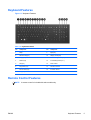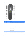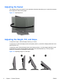
1
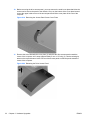
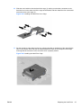
Hardware Reference Guide
HP TouchSmart 9300 Elite Business PC
© Copyright 2011 Hewlett-Packard
Development Company, L.P. The
information contained herein is subject to
change without notice.
Microsoft, Windows, and Windows Vista are
either trademarks or registered trademarks
of Microsoft Corporation in the United
States and/or other countries.
The only warranties for HP products and
services are set forth in the express
warranty statements accompanying such
products and services. Nothing herein
should be construed as constituting an
additional warranty. HP shall not be liable
for technical or editorial errors or omissions
contained herein.
This document contains proprietary
information that is protected by copyright.
No part of this document may be
photocopied, reproduced, or translated to
another language without the prior written
consent of Hewlett-Packard Company.
Hardware Reference Guide
HP TouchSmart 9300 Elite Business PC
First Edition (January 2011)
Document part number: 644511-001
About This Book
This guide provides basic information for upgrading this computer model.
WARNING! Text set off in this manner indicates that failure to follow directions could result in bodily
harm or loss of life.
CAUTION: Text set off in this manner indicates that failure to follow directions could result in
damage to equipment or loss of information.
NOTE:
ENWW
Text set off in this manner provides important supplemental information.
iii
iv
About This Book
ENWW
Table of contents
1 Product Features ............................................................................................................................................ 1
Overview .............................................................................................................................................. 1
Front Components ................................................................................................................................ 2
Side Components ................................................................................................................................. 3
Rear Components ................................................................................................................................ 4
Keyboard Features ............................................................................................................................... 5
Remote Control Features ..................................................................................................................... 5
Adjusting the Swivel ............................................................................................................................. 8
Adjusting the Height, Tilt, and Slope .................................................................................................... 8
2 Hardware Upgrades ........................................................................................................................................ 9
Warnings and Cautions ........................................................................................................................ 9
Connecting Power .............................................................................................................................. 10
Disconnecting Power .......................................................................................................................... 11
Installing the Rear Port Security Cover .............................................................................................. 12
Removing the Rear Port Security Cover ............................................................................................ 12
Installing Memory ............................................................................................................................... 13
DDR3-SDRAM SODIMMs ................................................................................................. 13
Populating SODIMM Sockets ............................................................................................ 14
Installing SODIMMS .......................................................................................................... 15
Replacing the Hard Drive ................................................................................................................... 21
Installing a Security Lock .................................................................................................................... 28
Attaching the Computer to a Mounting Fixture ................................................................................... 29
Synchronizing the Optional Wireless Keyboard or Mouse ................................................................. 29
Connecting the Computer to a Cable TV Source ............................................................................... 31
Connecting a Second Display ............................................................................................................ 33
Additional Information ......................................................................................................................... 35
Appendix A Electrostatic Discharge .............................................................................................................. 36
Preventing Electrostatic Damage ....................................................................................................... 36
Grounding Methods ............................................................................................................................ 36
Appendix B Computer Operating Guidelines, Routine Care and Shipping Preparation .......................... 37
Computer Operating Guidelines and Routine Care ............................................................................ 37
Optical Drive Precautions ................................................................................................................... 38
Shipping Preparation .......................................................................................................................... 38
ENWW
v
Index ................................................................................................................................................................... 39
vi
ENWW
1
Product Features
Overview
Figure 1-1 HP TouchSmart 9300 Elite Business PC
NOTE:
The wireless keyboard and mouse shown above are optional accessories.
The HP TouchSmart 9300 Elite Business PC offers the following features:
●
Integrated All-in-One form factor
●
23-inch diagonal widescreen WLED backlit BrightView LCD
●
Multitouch panel
●
Swivel pad and VESA mounting bracket under base of stand
●
Adjustable reclining stand
●
Intel® 2nd Generation Core™ i7, i5, or i3 processor
●
Intel H67 chipset
●
Genuine Windows 7 Professional Edition operating system
●
Integrated Intel HD Graphics, or discrete MXM graphics
●
Integrated Gigabit Network Connection (10/100/1000 NIC)
●
Optional wireless connectivity:
●
ENWW
◦
Integrated 802.11 a/b/g/n or b/g/n wireless LAN module
◦
Bluetooth® 3.0
Optional TV Tuner
Overview
1
●
Four SODIMM slots with up to 16 GB of DDR3 SDRAM memory and dual channel support
●
Up to 1 TB hard drive, or up to 300 GB Solid State Drive
●
HP SuperMulti DVD Writer or HP SuperMulti DVD Writer Drive
●
6-in-1 Media Card Reader
●
7 USB ports
●
DisplayPort
●
Integrated Full HD webcam, dual microphone array, and premium stereo speakers
●
Volume control and mute buttons
●
Security lock slot and rear port security cover
●
Removable panels on the back of the chassis allow administrators to easily and efficiently
service the PC
●
HP TouchSmart software suite for instant access to calendar, Internet, notes, and multimedia
content
●
ENERGY STAR® qualified, EPEAT® Gold registered, and offers 90-percent energy-efficient
power
●
Choice of wired or wireless keyboard and mouse
Front Components
Figure 1-2 Front Components
Table 1-1 Front Components
2
No.
Component
No.
Component
1
58.4 cm (23-inch) diagonal, 16:9 widescreen, touchenabled, full HD, white LED backlit LCD display
4
Dual wireless antenna
Chapter 1 Product Features
ENWW
Table 1-1 Front Components (continued)
No.
Component
No.
Component
2
Dual microphone array (optional)
5
High-performance stereo speakers
3
Webcam (optional)
6
IR Receiver (select models only)
Side Components
Figure 1-3 Side Components
Table 1-2 Side Components
ENWW
No.
Component
No.
Component
1
Volume up button
8
Microphone/line in jack
2
Volume down button
9
Headphone jack
3
Mute button
10
Slot-load optical drive (optional)
4
Hard drive activity LED
11
Optical drive eject button
5
Media card reader activity LED
12
Optical drive activity LED
6
Media card reader
13
Power LED
7
(2) USB 2.0 ports
14
Power button
Side Components
3
Rear Components
Figure 1-4 Rear Components
Table 1-3 Rear Components
4
No.
Component
No.
Component
1
Drive access panel
10
Power indicator light
2
Webcam adjustment wheel
11
Rear port security cover
3
Memory access panel
12
TV coax in (optional)
4
Adjustable reclining stand
13
IR Emitter (Blaster) output (optional)
5
Security lock slot
14
(4) USB 2.0 ports
6
Power connector release latch
15
Audio line out
7
Rear port access door
16
DisplayPort
8
USB port for optional wireless keyboard/mouse
receiver
17
RJ-45 Gigabit Ethernet port
9
Power connector
Chapter 1 Product Features
ENWW
Keyboard Features
Figure 1-5 Keyboard Features
Table 1-4 Keyboard Features
No.
Component
No.
Component
1
Sleep
9
Eject (F8)
2
Windows Help (F1)
10
Display On/Off (F9)
3
Replay (F2)
11
Decrease Brightness (F10)
4
Rewind (F3)
12
Increase Brightness (F11)
5
Stop (F4)
13
Mute Volume
6
Play/Pause (F5)
14
Decrease Volume
7
Fast Forward (F6)
15
Increase Volume
8
Skip (F7)
16
Internet
Remote Control Features
NOTE:
ENWW
A remote control is included with select models only.
Keyboard Features
5
Figure 1-6 Remote Control Features
Table 1-5 Remote Control Features
6
No.
Button
Function
1
On/Off
Puts the computer into and out of a power-reduced Sleep mode. It does not turn the
computer off.
2
Visualization
Displays visual imagery synchronized to the sound of the music tracks.
3
Music
(Windows Media Center only) Opens the Music Library window in Windows Media
Center.
4
Radio
(Windows Media Center only) Opens the FM Radio window in Windows Media Center.
5
Guide
(Windows Media Center only) Opens the Television Program Guide.
6
Recorded TV
(Windows Media Center only) Opens the recorded TV window where recorded TV
programs are displayed.
7
Arrows
Move the cursor to navigate and select actions.
8
DVD Menu
Opens the Play DVD window in Windows Media Center or opens the main menu of a
DVD movie, if available.
9
Back
Returns to the previous window.
10
More Info
Displays available information about a selected media file and displays other menus.
Chapter 1 Product Features
ENWW
Table 1-5 Remote Control Features (continued)
ENWW
No.
Button
Function
11
Start
Opens Windows Media Center main menu.
12
Volume
Increases (+) or decreases (–) volume.
13
Mute
Turns computer sound off. The word “Mute” displays onscreen when Mute is turned on.
14
Record
Records a selected television program and stores it on the hard disk drive.
15
Play
Plays the selected media.
16
Rewind
Moves the media backward at three speeds.
17
Skip Backward
Moves media backward 7 seconds or to the beginning of a music track or a DVD chapter.
18
0 through 9, *, ., #
Enters text and numbers into a search or text box. Pressing a number button repeatedly
toggles through the characters on that button. Press Enter to select a character.
19
Clear
Deletes the last character entered.
20
LED
Activity indicator light. The LED tells you that the remote control is emitting a signal when
you press a button.
21
Print
Prints the selected item.
22
Picture
(Windows Media Center only) Opens the Pictures Library window.
23
Video
(Windows Media Center only) Opens the Videos Library window.
24
Live TV
(Windows Media Center only) Displays the full-screen view of live TV. Moves a TV
program forward to the end of the pause buffer and resumes playing live TV.
25
OK
Selects the desired action or window option and acts as the Enter key.
26
Aspect
Changes the aspect ratio of the display. Zooms in on the picture three times, and then
returns to the full-screen aspect ratio.
27
Slide Show
(Windows Media Center only) Plays a slide show of all the pictures on the hard disk drive.
28
Ch+ and Ch–
Changes the TV channels or moves pages up and down, depending on available options.
Moves to the next DVD chapter.
29
Eject
Ejects a CD or DVD.
30
Pause
Pauses audio and video tracks and live or recorded TV programs.
31
Fast Forward
Moves the media forward at three speeds.
32
Skip Forward
Moves the media forward 30 seconds in videos and live TV, one music track, or one DVD
chapter.
33
Stop
Stops the media currently playing.
34
Enter
Selects the desired action, menu, or window option.
Remote Control Features
7
Adjusting the Swivel
The computer has a swivel wheel on the underside of the base that allows you to swivel the computer
left or right for the best viewing angle.
Figure 1-7 Adjusting Swivel
Adjusting the Height, Tilt, and Slope
To adjust the height , slide the display head up (1) or down.
To adjust the tilt, slide the display head to the highest position (1) and tilt the display head back to the
desired position (2).
To adjust the slope, slide the display head to the highest position (1), tilt the display head back to the
full tilt position (2), then slide the display head down to the desired position (3). The fully sloped
position is convenient for operating the touch screen.
Figure 1-8 Adjusting Height, Tilt, and Slope
8
Chapter 1 Product Features
ENWW
2
Hardware Upgrades
Warnings and Cautions
Before performing upgrades be sure to carefully read all of the applicable instructions, cautions, and
warnings in this guide.
WARNING! To reduce the risk of personal injury from electrical shock, hot surfaces, or fire:
Disconnect the power cord from the wall outlet and allow the internal system components to cool
before touching.
Do not plug telecommunications or telephone connectors into the network interface controller (NIC)
receptacles.
Do not disable the power cord grounding plug. The grounding plug is an important safety feature.
Plug the power cord in a grounded (earthed) outlet that is easily accessible at all times.
For your safety, do not place anything on power cords or cables. Arrange them so that no one may
accidentally step on or trip over them. Do not pull on a cord or cable. When unplugging from the
electrical outlet, grasp the cord by the plug.
To reduce the risk of serious injury, read the Safety & Comfort Guide. It describes proper workstation,
setup, posture, and health and work habits for computer users, and provides important electrical and
mechanical safety information. This guide is located on the Web at http://www.hp.com/ergo.
WARNING! Computers that are inappropriately situated on dressers, bookcases, shelves, desks,
speakers, chests, or carts may fall over and cause personal injury.
Care should be taken to route all cords and cables connected to the computer so that they can not be
pulled, grabbed, or tripped over.
WARNING! Energized and moving parts inside.
Disconnect power to the equipment before removing any access panels.
Replace and secure all access panels before re-energizing the equipment.
CAUTION: Static electricity can damage the electrical components of the computer or optional
equipment. Before beginning these procedures, ensure that you are discharged of static electricity by
briefly touching a grounded metal object. See Electrostatic Discharge on page 36 for more
information.
When the computer is plugged into an AC power source, voltage is always applied to the system
board. You must disconnect the power cord from the power source before opening the computer to
prevent damage to internal components.
ENWW
Warnings and Cautions
9
Connecting Power
1.
Squeeze the two tabs on the rear port access door at the back of the computer (1) and pull the
door open (2).
Figure 2-1 Opening the Rear Port Access Door
2.
Reach into the rear cavity framed by the computer stand and plug the power cord into the power
connection at the top right corner (1).
3.
Plug the three-pronged power plug into the power brick (2) and a power outlet (3).
Figure 2-2 Connecting Power
4.
10
Plug all peripheral cables into the appropriate ports as needed.
Chapter 2 Hardware Upgrades
ENWW
5.
Close the rear port access door.
Figure 2-3 Closing the Rear Port Access Door
Disconnecting Power
1.
Remove all removable media, such as compact discs or USB flash drives, from the computer.
2.
Turn off the computer properly through the operating system, then turn off any external devices.
3.
If a security lock is installed on the rear of the computer, remove the lock.
4.
If the rear port security cover is installed, remove the cover.
5.
Open the rear port access door.
6.
Press on the power cord release latch (1) and pull the power cord connector from the port (2).
Figure 2-4 Disconnecting Power
ENWW
Disconnecting Power
11
Installing the Rear Port Security Cover
1.
Ensure that all cables are connected and the rear port access door is closed.
2.
Tilt the display head to its most forward position and slide it down to its lowest position so that
the stand does not cover any of the center cavity.
3.
Place the port security cover into the cavity ensuring that the cables are fitted into the slots on
the security cover (1) and tighten the captive screw (2).
Figure 2-5 Installing the Rear Port Security Cover
NOTE: You can further secure the rear ports by installing a security lock into the slot just above the
captive screw on the rear port security cover. Refer to Installing a Security Lock on page 28.
Removing the Rear Port Security Cover
12
1.
Tilt the display head to its most forward position and slide it down to its lowest position so that
the stand does not interfere with removing the port security cover.
2.
If a security lock is installed on the rear of the unit, remove the lock.
Chapter 2 Hardware Upgrades
ENWW
3.
Loosen the captive screw (1) and slide the security cover out of the center cavity (2).
Figure 2-6 Removing the Rear Port Security Cover
Installing Memory
The computer comes with double data rate 3 synchronous dynamic random access memory (DDR3SDRAM) small outline dual inline memory modules (SODIMMs).
DDR3-SDRAM SODIMMs
For proper system operation, the SODIMMs must be:
●
industry-standard 204-pin
●
unbuffered non-ECC PC3-10600 DDR3-1333 MHz-compliant
●
1.5 volt DDR3-SDRAM SODIMMs
The DDR3-SDRAM SODIMMs must also:
●
support CAS latency 9 DDR3 1333 MHz (9-9-9 timing)
●
contain the mandatory Joint Electronic Device Engineering Council (JEDEC) specification
In addition, the computer supports:
●
512-Mbit, 1-Gbit, and 2-Gbit non-ECC memory technologies
●
single-sided and double-sided SODIMMs
●
SODIMMs constructed with x8 and x16 devices; SODIMMs constructed with x4 SDRAM are not
supported
NOTE:
ENWW
The system will not operate properly if you install unsupported SODIMMs.
Installing Memory
13
Populating SODIMM Sockets
The memory sockets on the system board can be populated with up to four industry-standard
SODIMMs. These memory sockets are populated with at least one preinstalled SODIMM. To achieve
the maximum memory support, you can populate the system board with up to 16 GB of memory.
There are four SODIMM sockets on the system board, with two sockets per channel. The sockets are
labeled DIMM1, DIMM2, DIMM3, and DIMM4. Sockets DIMM1 and DIMM2 operate in memory
channel A. Sockets DIMM3 and DIMM4 operate in memory channel B.
Figure 2-7 SODIMM Socket Locations
Table 2-1 SODIMM Socket Locations
Item
Description
Socket Color
1
DIMM1 socket, Channel A (populate first)
black
2
DIMM2 socket, Channel A (populate third)
white
3
DIMM3 socket, Channel B (populate second)
black
4
DIMM4 socket, Channel B (populate fourth)
white
NOTE: A SODIMM must occupy the black DIMM1 socket. Otherwise, the system will display
a POST error message indicating that a memory module is installed in the wrong socket
14
Chapter 2 Hardware Upgrades
ENWW
The system will automatically operate in single channel mode, dual channel mode, or flex mode,
depending on how the SODIMMs are installed.
●
The system will operate in single channel mode if the SODIMM sockets are populated in one
channel only.
●
The system will operate in a higher-performing dual channel mode if the total memory capacity
of the SODIMMs in Channel A is equal to the total memory capacity of the SODIMMs in Channel
B. The technology and device width can vary between the channels. For example, if Channel A
is populated with two 1 GB SODIMMs and Channel B is populated with one 2 GB SODIMM, the
system will operate in dual channel mode.
●
The system will operate in flex mode if the total memory capacity of the SODIMMs in Channel A
is not equal to the total memory capacity of the SODIMMs in Channel B. In flex mode, the
channel populated with the least amount of memory describes the total amount of memory
assigned to dual channel and the remainder is assigned to single channel. For optimal speed,
the channels should be balanced so that the largest amount of memory is spread between the
two channels. If one channel will have more memory than the other, the larger amount should be
assigned to Channel A. For example, if you are populating the sockets with one 2 GB SODIMM,
and three 1 GB SODIMMs, Channel A should be populated with the 2 GB SODIMM and one 1
GB SODIMM, and Channel B should be populated with the other two 1 GB SODIMMs. With this
configuration, 4 GB will run as dual channel and 1 GB will run as single channel.
Installing SODIMMS
When facing the rear of the computer, there are four memory sockets located behind the large access
panel on the right. You must remove this panel to remove or install memory.
CAUTION: Static electricity can damage the electronic components of the computer. Before
beginning these procedures, ensure that you are discharged of static electricity by briefly touching a
grounded metal object. For more information, refer to Electrostatic Discharge on page 36.
When handling a memory module, be careful not to touch any of the contacts. Doing so may damage
the module.
To remove or install memory modules:
1.
Remove all removable media, such as compact discs or USB flash drives, from the computer.
2.
Turn off the computer properly through the operating system, then turn off any external devices.
3.
Disconnect the power cord from the power outlet and disconnect any external devices.
CAUTION: You must disconnect the power cord and wait approximately 30 seconds for the
power to drain before adding or removing memory modules. Regardless of the power-on state,
voltage is always supplied to the memory modules as long as the computer is plugged into an
active AC outlet. Adding or removing memory modules while voltage is present may cause
irreparable damage to the memory modules or system board.
ENWW
4.
If a security lock is installed on the rear of the computer, remove the lock.
5.
If the rear port security cover is installed, remove the cover.
6.
Open the rear port access door.
7.
Disconnect all cables from the rear ports.
8.
Place the computer face down on a soft flat surface. HP recommends that you set down a
blanket, towel, or other soft cloth to protect the screen surface from scratches or other damage.
Installing Memory
15
9.
Remove the small center panel below the rear ports by pulling out the top of the panel (1) then
lifting the panel off the computer (2).
Figure 2-8 Removing the Center Panel
10. Before removing the memory access panel, you must remove the small cover plate that hides
the screw used to secure the panel to the chassis. Lift up on the bottom of the cover plate
located next to the upper inside corner of the access panel and lift the cover plate off the rear of
the computer.
Figure 2-9 Removing the Access Panel Screw Cover Plate
16
Chapter 2 Hardware Upgrades
ENWW
11. Remove the screw beneath the cover plate (1) and slide the memory access panel toward the
center of the computer until it stops (approximately 5 mm or 1/5 inch) (2). Use the raised grip
areas on the top and bottom inside corners of the access panel to slide the panel toward the
center of the computer.
Figure 2-10 Releasing the Memory Access Panel
12. Lift up the outside edge of the panel approximately 2.5 cm (1 inch) (1) and slide the panel toward
the outside edge of the computer (2) to remove it.
Figure 2-11 Removing the Memory Access Panel
ENWW
Installing Memory
17
13. To remove a SODIMM, press outward on the two latches on each side of the SODIMM (1) then
pull the SODIMM out of the socket (2).
Figure 2-12 Removing a Memory Module
14. To install a SODIMM, slide the new SODIMM into the socket at approximately a 30° angle (1)
then press the SODIMM down (2) so that the latches lock it in place.
Figure 2-13 Installing a Memory Module
NOTE: A memory module can be installed in only one way. Match the notch on the module
with the tab on the memory socket.
18
Chapter 2 Hardware Upgrades
ENWW
15. To replace the memory access panel, hold the panel at a slight angle with the inside edge of the
panel lower than the outside edge, then slide the screw hole tab on the top inside corner of the
panel into the slot on the rear of the computer.
Figure 2-14 Replacing the Memory Access Panel
16. Lower the outside edge of the panel onto the computer then slide the panel towards the outside
of the computer (1) and install the screw (2) to secure the panel in place.
Figure 2-15 Replacing the Memory Access Panel
ENWW
Installing Memory
19
17. Replace the screw cover plate, pressing the top of the cover plate in position first then pressing
the bottom of the cover plate in position.
Figure 2-16 Replacing the Access Panel Screw Cover Plate
18. Replace the small center panel below the rear ports by inserting the bottom of the panel into
position first (1) then rotating the top of the panel onto the computer so that it snaps in place (2).
Figure 2-17 Replacing the Center Panel
19. Reconnect all cables that were removed from the rear ports.
20. Close the rear port access door.
21. If the rear port security cover was removed, replace the cover.
22. If a security lock was installed on the rear of the computer, replace the lock.
23. Reconnect the power cord into the wall outlet and turn on the computer. The computer
automatically recognizes the additional memory when you turn on the computer.
20
Chapter 2 Hardware Upgrades
ENWW
Replacing the Hard Drive
The hard drive is located under the drive access panel on the left side of the computer (when viewed
from behind). The drive is secured with one captive screw and is housed in a removable cage.
CAUTION: Static electricity can damage the electronic components of the computer. Before
beginning these procedures, ensure that you are discharged of static electricity by briefly touching a
grounded metal object. For more information, refer to Electrostatic Discharge on page 36.
NOTE: Depending on your computer configuration, the hard drive may be a 2.5-inch drive or a 3.5inch drive. The 2.5-inch drive is installed in a housing that is the same size as 3.5-inch drive.
Therefore, either drive will fit into the existing hard drive cage.
To replace the hard drive:
1.
Remove all removable media, such as compact discs or USB flash drives, from the computer.
2.
Turn off the computer properly through the operating system, then turn off any external devices.
3.
Disconnect the power cord from the power outlet and disconnect any external devices.
CAUTION: Regardless of the power-on state, voltage is always present on the system board
as long as the system is plugged into an active AC outlet. You must disconnect the power cord
to avoid damage to the internal components of the computer.
4.
If a security lock is installed on the rear of the computer, remove the lock.
5.
If the rear port security cover is installed, remove the cover.
6.
Open the rear port access door.
7.
Disconnect all cables from the rear ports.
8.
Place the computer face down on a soft flat surface. HP recommends that you set down a
blanket, towel, or other soft cloth to protect the screen surface from scratches or other damage.
9.
Remove the small center panel below the rear ports by pulling out the top of the panel (1) then
lifting the panel off the computer (2).
Figure 2-18 Removing the Center Panel
ENWW
Replacing the Hard Drive
21
10. Before removing the drive access panel, you must remove the small cover plate that hides the
screw used to secure the panel to the chassis. Lift up on the bottom of the cover plate located
next to the upper inside corner of the access panel and lift the cover plate off the rear of the
computer.
Figure 2-19 Removing the Access Panel Screw Cover Plate
11. Remove the screw beneath the cover plate (1) and slide the drive access panel toward the
center of the computer until it stops (approximately 5 mm or 1/5 inch) (2). Use the raised grip
areas on the top and bottom inside corners of the access panel to slide the panel toward the
center of the computer.
Figure 2-20 Releasing the Drive Access Panel
22
Chapter 2 Hardware Upgrades
ENWW
12. Lift up the outside edge of the panel approximately 2.5 cm (1 inch) (1) and slide the panel toward
the outside edge of the computer (2) to remove it.
Figure 2-21 Removing the Drive Access Panel
13. Loosen the captive screw on the side of the hard drive cage that secures the cage to the
computer.
Figure 2-22 Loosening the Hard Drive Cage Screw
ENWW
Replacing the Hard Drive
23
14. Grasp the handle on top of the hard drive cage and slide the cage toward the outer edge of the
computer, then lift the cage out of the computer.
Figure 2-23 Removing the Hard Drive Cage
15. To remove the hard drive from the hard drive cage, remove the four screws on the sides of the
cage that secure the drive to the cage (1), and then slide the drive out of the cage (2).
Figure 2-24 Removing the Hard Drive from the Cage
24
Chapter 2 Hardware Upgrades
ENWW
16. Slide the new hard drive into the hard drive cage (1) making sure that the connectors on the
hard drive are on the same end of the cage as the handle, and then install the four screws that
secure the drive to the cage (2).
Figure 2-25 Installing the Hard Drive in the Cage
17. Set the hard drive cage down into the bay, aligning the tabs on the bottom of the cage with the
tabs on the chassis, then slide the drive back toward the center of the computer until it stops,
ensuring that the connector on the end of the drive is properly seated.
Figure 2-26 Installing the Hard Drive Cage
ENWW
Replacing the Hard Drive
25
18. Tighten the captive screw to secure the hard drive cage in place.
Figure 2-27 Tightening the Hard Drive Cage Screw
19. To replace the drive access panel, hold the panel at a slight angle with the inside edge of the
panel lower than the outside edge, then slide the screw hole tab on the top inside corner of the
panel into the slot on the rear of the computer.
Figure 2-28 Replacing the Drive Access Panel
26
Chapter 2 Hardware Upgrades
ENWW
20. Lower the outside edge of the panel onto the computer then slide the panel towards the outside
of the computer (1) and install the screw (2) to secure the panel in place.
Figure 2-29 Replacing the Drive Access Panel
21. Replace the screw cover plate, pressing the top of the cover plate in position first then pressing
the bottom of the cover plate in position.
Figure 2-30 Replacing the Access Panel Screw Cover Plate
ENWW
Replacing the Hard Drive
27
22. Replace the small center panel below the rear ports by inserting the bottom of the panel into
position first (1) then rotating the top of the panel onto the computer so that it snaps in place (2).
Figure 2-31 Replacing the Center Panel
23. Reconnect all cables that were removed from the rear ports.
24. Close the rear port access door.
25. If the rear port security cover was removed, replace the cover.
26. If a security lock was installed on the rear of the computer, replace the lock.
27. Reconnect the power cord into the wall outlet and turn on the computer.
Installing a Security Lock
A security lock (sold separately) enables you to secure your computer from access to the rear ports
(when a rear port security cover is installed) and theft. A security lock is a key lock device that has a
28
Chapter 2 Hardware Upgrades
ENWW
wire cable attached. You attach one end of the cable to your desk (or other stationary object) and the
other end of the cable to the security slot on the computer. Secure the security lock with the key.
Figure 2-32 Installing a Security Lock
Attaching the Computer to a Mounting Fixture
You can remove the computer from the stand and install it on a wall, monitor arm, or other mounting
fixture. There is a VESA adapter plate attached to the underside of the computer stand that is used
for mounting the computer.
Table 2-2 Mounting Specifications
Computer Dimensions (without stand)
Height
405.2 mm
15.953 inches
Width
584.5 mm
23.012 inches
Depth
86 mm
3.78 inches
Integrated Graphics
8.75 kg
19.29 lbs
Discrete Graphics
9.05 kg
19.95 lbs
VESA standard adapter plate hole patterns (height x width)
100 mm x 100 mm
3.937 in x 3.937 in
100 mm x 200 mm
3.937 in x 7.874 in
Computer Weight (without stand, with VESA adapter plate)
For instructions on mounting the computer, refer to the Wall-Mounting your HP TouchSmart User
Guide.
Synchronizing the Optional Wireless Keyboard or Mouse
The optional wireless keyboard and mouse are easy to set up. Just remove the battery tabs on both
the keyboard and the mouse. Also, make sure the Power switch on the bottom of the mouse is in the
ENWW
Attaching the Computer to a Mounting Fixture
29
On position (the keyboard does not have a Power switch). Then, turn on the computer. If you have
trouble using the keyboard and mouse, manually synchronize them as described below.
NOTE: For better mouse battery life and performance, avoid using your mouse on a dark or highgloss surface, and turn mouse power off when not in use.
The wireless keyboard and mouse are pre-synchronized to work with your computer. The keyboard
and mouse should work immediately after you first pull the battery tabs to activate the preinstalled
batteries, and then turn on the mouse.
You may need to manually synchronize the wireless keyboard or mouse if they are not functioning.
To synchronize them:
1.
Make sure the keyboard and mouse are next to the computer, within 30 cm (1 foot) and away
from interference from other devices.
2.
Turn on the computer.
3.
Open the rear port access door.
4.
Insert the wireless receiver into the designated wireless receiver USB port on the computer
located below the other rear ports.
Figure 2-33 Installing the Wireless Receiver
30
5.
Make sure the Power switch on the bottom of the mouse is in the On position (1).
6.
Press the Connect button on the bottom of the mouse (2) for fives seconds. The blue activity
LED from the wireless receiver illuminates when the synchronization command has been
received and turns off when synchronization is complete.
Chapter 2 Hardware Upgrades
ENWW
7.
Press the Connect button on the bottom of the keyboard (3) for five seconds. The blue activity
LED from the wireless receiver illuminates when the synchronization command has been
received and turns off when synchronization is complete.
Figure 2-34 Synchronizing the Wireless Keyboard and Mouse
8.
Close the rear port access door.
NOTE: If the procedure does not work, remove and then re-insert the wireless keyboard and mouse
receiver from the back of the computer and then synchronize the keyboard and mouse again.
Connecting the Computer to a Cable TV Source
NOTE:
A TV tuner is included with select models only.
To connect the computer to a cable TV source:
ENWW
1.
Turn off power to the computer and the set-top box.
2.
Open the rear port access door on the computer.
3.
Connect a coaxial cable between the coaxial connector on the rear of the computer (1) and the
set-top box (2).
Connecting the Computer to a Cable TV Source
31
To use the remote control with a set-top box:
1.
To use the remote control so that the signal is received by the computer, connect an IR emitter
(blaster) cable to the IR Out connector on the computer (3), remove the paper from the backing
tape on the end of the IR emitter cable (4), and then press the end of the cable over the remote
IR sensor (receiver) window on the set-top box (5).
NOTE: The IR emitter cable is a remote control sensing device that connects to the computer
and covers the remote sensor on a set-top box. When you are selecting TV channels, it enables
the remote control to work with your set-top box.
Figure 2-35 Connecting the Computer to a Set-Top Box
32
2.
Close the rear port access door on the computer.
3.
Turn on power to the computer and the set-top box.
Chapter 2 Hardware Upgrades
ENWW
4.
When you use the remote control, point it at the front of the computer, not at the set-top box.
Figure 2-36 Using the Remote Control
Connecting a Second Display
The DisplayPort on the rear of the computer allows you to connect a second display, such as a
monitor or TV, to the computer.
If you are adding a second display that has a DisplayPort, then no DisplayPort video adapter is
required. If you are adding a second display that does not have a DisplayPort, you can purchase a
DisplayPort video adaptor from HP for your configuration.
DisplayPort adapters and video cables are purchased separately. HP offers the following adapters:
●
DisplayPort to VGA adapter
●
DisplayPort to DVI adapter
●
DisplayPort to HDMI adapter
To connect a second display:
ENWW
1.
Turn off power to the computer and the second display that you are connecting to the computer.
2.
Open the rear port access door on the computer.
Connecting a Second Display
33
3.
If your second display has a DisplayPort, connect a DisplayPort cable directly between the
DisplayPort on the rear of the computer (1) and the DisplayPort on the second display (2).
Figure 2-37 Connecting a Second Display
4.
If your second display does not have a DisplayPort, connect a DisplayPort video adapter to the
DisplayPort on the rear I/O panel (1). Then connect a cable (VGA, DVI. or HDMI, depending on
your application) between the adapter (2) and a second display (3).
Figure 2-38 Connecting a Second Display Using a DisplayPort Adapter
5.
Close the rear port access door on the computer.
6.
Turn on power to the computer and the second display.
NOTE: Use the graphics card software or the Windows Display Settings to configure the second
display as a mirrored image of the primary display or an extension of the primary display.
34
Chapter 2 Hardware Upgrades
ENWW
Additional Information
For more information on removing and replacing hardware components, desktop management, the
Computer Setup utility, and troubleshooting, refer to the Maintenance and Service Guide (available in
English only) for your computer model at http://www.hp.com.
ENWW
Additional Information
35
A
Electrostatic Discharge
A discharge of static electricity from a finger or other conductor may damage system boards or other
static-sensitive devices. This type of damage may reduce the life expectancy of the device.
Preventing Electrostatic Damage
To prevent electrostatic damage, observe the following precautions:
●
Avoid hand contact by transporting and storing products in static-safe containers.
●
Keep electrostatic-sensitive parts in their containers until they arrive at static-free workstations.
●
Place parts on a grounded surface before removing them from their containers.
●
Avoid touching pins, leads, or circuitry.
●
Always be properly grounded when touching a static-sensitive component or assembly.
Grounding Methods
There are several methods for grounding. Use one or more of the following methods when handling
or installing electrostatic-sensitive parts:
●
Use a wrist strap connected by a ground cord to a grounded workstation or computer chassis.
Wrist straps are flexible straps with a minimum of 1 megohm +/- 10 percent resistance in the
ground cords. To provide proper ground, wear the strap snug against the skin.
●
Use heelstraps, toestraps, or bootstraps at standing workstations. Wear the straps on both feet
when standing on conductive floors or dissipating floor mats.
●
Use conductive field service tools.
●
Use a portable field service kit with a folding static-dissipating work mat.
If you do not have any of the suggested equipment for proper grounding, contact an HP authorized
dealer, reseller, or service provider.
NOTE: For more information on static electricity, contact an HP authorized dealer, reseller, or
service provider.
36
Appendix A Electrostatic Discharge
ENWW
B
Computer Operating Guidelines,
Routine Care and Shipping Preparation
Computer Operating Guidelines and Routine Care
Follow these guidelines to properly set up and care for the computer:
ENWW
●
Keep the computer away from excessive moisture, direct sunlight, and extremes of heat and
cold.
●
Operate the computer on a sturdy, level surface. Leave a 10.2-cm (4-inch) clearance on all
vented sides of the computer to permit the required airflow.
●
Never restrict the airflow into the computer by blocking any vents or air intakes.
●
Never operate the computer with the any of the access panels removed.
●
Do not place computers so near each other that they are subject to each other’s re-circulated or
preheated air.
●
If the computer is to be operated within a separate enclosure, intake and exhaust ventilation
must be provided on the enclosure, and the same operating guidelines listed above will still
apply.
●
Keep liquids away from the computer and keyboard.
●
Never cover the ventilation slots with any type of material.
●
Install or enable power management functions of the operating system or other software,
including sleep states.
●
When cleaning the computer turn off power to the computer and unplug the power cord before
you do any of the following:
◦
Wipe the exterior of the computer with a soft, damp cloth as needed. Using cleaning
products may discolor or damage the finish.
◦
Do not use cleaners that contain any petroleum based materials such as benzene, thinner,
or any volatile substance to clean the screen or cabinet. These chemicals may damage the
computer.
◦
Wipe the screen with a soft, clean antistatic cloth. For more difficult cleaning situations, use
a 50/50 mix of water and Isopropyl alcohol. Spray the cleaner onto a cloth and use the
damp cloth to gently wipe the screen surface. Never spray the cleaner directly on the
screen surface. It may run behind the bezel and damage the electronics.
◦
Occasionally clean the air vents on all vented sides of the computer. Lint, dust, and other
foreign matter can block the vents and limit the airflow.
Computer Operating Guidelines and Routine Care
37
Optical Drive Precautions
Be sure to observe the following guidelines while operating or cleaning the optical drive.
●
Do not move the drive during operation. This may cause it to malfunction during reading.
●
Avoid exposing the drive to sudden changes in temperature, as condensation may form inside
the unit. If the temperature suddenly changes while the drive is on, wait at least one hour before
you turn off the power. If you operate the unit immediately, it may malfunction while reading.
●
Avoid placing the drive in a location that is subject to high humidity, extreme temperatures,
mechanical vibration, or direct sunlight.
CAUTION: If any object or liquid falls into the drive, immediately unplug the computer and have it
checked by an authorized HP service provider.
Shipping Preparation
Follow these suggestions when preparing to ship the computer:
1.
Back up the hard drive files on PD discs, tape cartridges, CDs, or USB flash drives. Be sure that
the backup media is not exposed to electrical or magnetic impulses while stored or in transit.
NOTE: The hard drive locks automatically when the system power is turned off.
2.
Remove and store all removable media.
3.
Turn off the computer and external devices.
4.
Disconnect the power cord from the electrical outlet, then from the computer.
5.
Disconnect the system components and external devices from their power sources, then from
the computer.
NOTE: Ensure that all boards are seated properly and secured in the board slots before
shipping the computer.
6.
38
Pack the system components and external devices in their original packing boxes or similar
packaging with sufficient packing material to protect them.
Appendix B Computer Operating Guidelines, Routine Care and Shipping Preparation
ENWW
Index
D
DisplayPort video adapter
connecting 33
M
memory
installing 13
populating sockets 14
removing 15
specifications 13
mounting the computer 29
mouse
synchronizing wireless 29
E
electrostatic discharge, preventing
damage 36
O
optical drive
precautions 38
F
features
front components 2
keyboard 5
overview 1
rear components 4
remote control 5
side components 3
P
power
connecting 10
disconnecting 11
A
additional information
35
C
computer operating guidelines
H
hard drive
replacing 21
height adjustment
37
W
warnings and cautions 9
R
rear port security cover
installing 12
removing 12
remote control 5
I
installation guidelines 9
installing
hard drive 21
memory 13
second display 33
security lock 28
IR emitter
connecting 31
S
second display connection 33
security
lock installation 28
rear port cover 12
shipping preparation 38
slope adjustment 8
specifications
memory 13
swivel adjustment 8
synchronizing wireless keyboard
and mouse 29
K
keyboard
features 5
synchronizing wireless 29
T
tilt adjustment 8
TV tuner
connecting 31
8
VESA mounting holes 29
V
ventilation guidelines 37
ENWW
Index
39