1
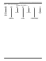
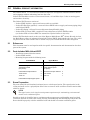
Precision Cooling
For Business-Critical Continuity™
Liebert® XDCF™
User Manual–10kW / 2.8 Tons / 34,000 BTUh
IMPORTANT SAFETY GUIDELINES
SAVE THESE INSTRUCTIONS
! CAUTION
Risk of piping and component rupture. May cause injury or equipment damage.
Closing service valves may isolate liquid refrigerant, causing high pressure and rupture of
piping. Do not close valves without follow recommended procedures for repair, maintenance
and replacement of components. Installing pressure relief valves in field piping that may
become isolated by service valves.
Fluorinated Greenhouse Gas Requirements—European Union
Stationary air conditioning, refrigeration, heat pump equipments and stationary fire protection systems in
the European Community market and operating with fluorinated greenhouse gases (f-gas), such as R407C,
R134a, R410A, must comply with the F-Gas Regulation: (EC) No. 842/2006 (F-gas). The regulation prohibits,
among other actions, venting fluorinated greenhouse gases to the atmosphere.
The F-Gas Regulation also requires operators to use use all measures that are technically feasible and do not
entail disproportionate cost to prevent leakage of these gases, to test for leakage regularly and to recover f-gas
during equipment service and maintenance and before disposing of equipment.
Refer to the full regulation for additional details.
TABLE OF CONTENTS
IMPORTANT SAFETY GUIDELINES . . . . . . . . . . . . . . . . . . . . . . . . . . . . . . . . . . INSIDE FRONT COVER
1.0
LIEBERT XDCF COMPONENT LOCATIONS AND MODEL NUMBER NOMENCLATURE . . . . . . . .1
2.0
GENERAL PRODUCT INFORMATION . . . . . . . . . . . . . . . . . . . . . . . . . . . . . . . . . . . . . . . . . . .3
2.1
References . . . . . . . . . . . . . . . . . . . . . . . . . . . . . . . . . . . . . . . . . . . . . . . . . . . . . . . . . . . . . . . . . . 3
2.2
Parts Included With Liebert XDCF. . . . . . . . . . . . . . . . . . . . . . . . . . . . . . . . . . . . . . . . . . . . . . 3
2.3
Room Preparation. . . . . . . . . . . . . . . . . . . . . . . . . . . . . . . . . . . . . . . . . . . . . . . . . . . . . . . . . . . . 3
2.4
Product/System Description . . . . . . . . . . . . . . . . . . . . . . . . . . . . . . . . . . . . . . . . . . . . . . . . . . . 4
2.5
Equipment Inspection . . . . . . . . . . . . . . . . . . . . . . . . . . . . . . . . . . . . . . . . . . . . . . . . . . . . . . . . 4
2.5.1
2.6
Unit Handling. . . . . . . . . . . . . . . . . . . . . . . . . . . . . . . . . . . . . . . . . . . . . . . . . . . . . . . . . . . . . . . . 4
Unpacking the Liebert XDCF . . . . . . . . . . . . . . . . . . . . . . . . . . . . . . . . . . . . . . . . . . . . . . . . . . 5
2.6.1
Recyclable Packaging . . . . . . . . . . . . . . . . . . . . . . . . . . . . . . . . . . . . . . . . . . . . . . . . . . . . . . . . . . 5
3.0
MECHANICAL CONSIDERATIONS . . . . . . . . . . . . . . . . . . . . . . . . . . . . . . . . . . . . . . . . . . . . .6
4.0
INSTALLATION . . . . . . . . . . . . . . . . . . . . . . . . . . . . . . . . . . . . . . . . . . . . . . . . . . . . . . . . . .7
4.1
References . . . . . . . . . . . . . . . . . . . . . . . . . . . . . . . . . . . . . . . . . . . . . . . . . . . . . . . . . . . . . . . . . . 7
4.2
Installation Considerations . . . . . . . . . . . . . . . . . . . . . . . . . . . . . . . . . . . . . . . . . . . . . . . . . . . . 7
4.3
Mounting Lower Liebert XDCF Module . . . . . . . . . . . . . . . . . . . . . . . . . . . . . . . . . . . . . . . . . . 8
4.3.1
4.3.2
4.4
Preparing the Lower Module for Attachment . . . . . . . . . . . . . . . . . . . . . . . . . . . . . . . . . . . . . . . 8
Attaching Lower Liebert XDCF Module . . . . . . . . . . . . . . . . . . . . . . . . . . . . . . . . . . . . . . . . . . . 9
Attaching Upper Liebert XDCF Module . . . . . . . . . . . . . . . . . . . . . . . . . . . . . . . . . . . . . . . . . 11
4.4.1
4.4.2
Preparing the Upper Module for Attachment. . . . . . . . . . . . . . . . . . . . . . . . . . . . . . . . . . . . . . 11
Attaching Upper Liebert XDCF Module . . . . . . . . . . . . . . . . . . . . . . . . . . . . . . . . . . . . . . . . . . 12
5.0
PIPING CONNECTIONS AND PIPING ACCESS POINTS . . . . . . . . . . . . . . . . . . . . . . . . . . . . . 13
5.1
European Union Fluorinated Greenhouse Gas Requirements . . . . . . . . . . . . . . . . . . . . . . . 13
5.2
Connection Methods and Points . . . . . . . . . . . . . . . . . . . . . . . . . . . . . . . . . . . . . . . . . . . . . . . 13
5.2.1
Header System . . . . . . . . . . . . . . . . . . . . . . . . . . . . . . . . . . . . . . . . . . . . . . . . . . . . . . . . . . . . . . 13
5.3
Recommended Piping Size . . . . . . . . . . . . . . . . . . . . . . . . . . . . . . . . . . . . . . . . . . . . . . . . . . . . 14
5.4
Connecting Liebert XD Flex Pipes to Liebert XDCF Modules. . . . . . . . . . . . . . . . . . . . . . . . 14
5.5
Connecting a Liebert XDCF with Liebert XD Flex Pipe to an Operational Liebert
XD System . . . . . . . . . . . . . . . . . . . . . . . . . . . . . . . . . . . . . . . . . . . . . . . . . . . . . . . . . . . . . . . . 14
5.6
Disconnecting a Liebert XDCF With Liebert XD Flex Pipe From a Liebert XD System . . . 16
5.7
Insulation . . . . . . . . . . . . . . . . . . . . . . . . . . . . . . . . . . . . . . . . . . . . . . . . . . . . . . . . . . . . . . . . . 17
6.0
CHECKLIST FOR PROPER INSTALLATION . . . . . . . . . . . . . . . . . . . . . . . . . . . . . . . . . . . . . .18
7.0
MAINTENANCE . . . . . . . . . . . . . . . . . . . . . . . . . . . . . . . . . . . . . . . . . . . . . . . . . . . . . . . . . 19
7.1
Fluorinated Greenhouse Gas Requirements. . . . . . . . . . . . . . . . . . . . . . . . . . . . . . . . . . . . . . 19
8.0
SPECIFICATIONS . . . . . . . . . . . . . . . . . . . . . . . . . . . . . . . . . . . . . . . . . . . . . . . . . . . . . . . .20
i
FIGURES
Figure 1
Figure 2
Figure 3
Figure 4
Figure 5
Figure 6
Figure 7
Figure 8
Figure 9
Figure 10
Figure 11
Figure 12
Figure 13
Figure 14
Figure 15
Figure 16
Figure 17
Liebert XDCF component locations . . . . . . . . . . . . . . . . . . . . . . . . . . . . . . . . . . . . . . . . . . . . . . . . . . 1
Model number nomenclature . . . . . . . . . . . . . . . . . . . . . . . . . . . . . . . . . . . . . . . . . . . . . . . . . . . . . . . 2
Liebert XDCF hydraulic diagram . . . . . . . . . . . . . . . . . . . . . . . . . . . . . . . . . . . . . . . . . . . . . . . . . . . 4
Unpacking the Liebert XDCF. . . . . . . . . . . . . . . . . . . . . . . . . . . . . . . . . . . . . . . . . . . . . . . . . . . . . . . 5
Overall dimensions . . . . . . . . . . . . . . . . . . . . . . . . . . . . . . . . . . . . . . . . . . . . . . . . . . . . . . . . . . . . . . . 6
Liebert XDCF unit mounting locations . . . . . . . . . . . . . . . . . . . . . . . . . . . . . . . . . . . . . . . . . . . . . . . 7
Lower Liebert XDCF attachments . . . . . . . . . . . . . . . . . . . . . . . . . . . . . . . . . . . . . . . . . . . . . . . . . . . 8
Locator hole for lower unit stud . . . . . . . . . . . . . . . . . . . . . . . . . . . . . . . . . . . . . . . . . . . . . . . . . . . . . 9
Liebert XD Flex Pipe support panel attachment . . . . . . . . . . . . . . . . . . . . . . . . . . . . . . . . . . . . . . 10
Upper Liebert XDCF attachment. . . . . . . . . . . . . . . . . . . . . . . . . . . . . . . . . . . . . . . . . . . . . . . . . . . 11
Attaching Liebert XD Flex Pipe retainers . . . . . . . . . . . . . . . . . . . . . . . . . . . . . . . . . . . . . . . . . . . . 12
Liebert XDCF supply and return piping access points . . . . . . . . . . . . . . . . . . . . . . . . . . . . . . . . . . 13
Liebert XD prefabricated piping assembly . . . . . . . . . . . . . . . . . . . . . . . . . . . . . . . . . . . . . . . . . . . 15
Detail view of Liebert XD Flex Pipe and prefabricated piping port. . . . . . . . . . . . . . . . . . . . . . . . 15
Liebert XD system with prefabricated piping assembly and Liebert XD Flex Pipe . . . . . . . . . . 16
Profile view of the Liebert XD system . . . . . . . . . . . . . . . . . . . . . . . . . . . . . . . . . . . . . . . . . . . . . . . 17
Piping mains without Liebert XDCF and Liebert XD Flex Pipe . . . . . . . . . . . . . . . . . . . . . . . . . . 17
TABLES
Table 1
Table 2
Branch piping sizes for refrigerant loop . . . . . . . . . . . . . . . . . . . . . . . . . . . . . . . . . . . . . . . . . . . . . 14
Liebert XDCF specifications. . . . . . . . . . . . . . . . . . . . . . . . . . . . . . . . . . . . . . . . . . . . . . . . . . . . . . . 20
ii
Liebert XDCF Component Locations and Model Number Nomenclature
1.0
LIEBERT XDCF COMPONENT LOCATIONS AND MODEL NUMBER
NOMENCLATURE
Figure 1
Liebert XDCF component locations
Gasket along edge of deflector
panel not shown for clarity
Mounting
Bracket
Top Deflector Panel
(2 pieces)
Return Port
Connection
Supply Port
Connection
Serial
Tag
Coil
Insulation
Strip
Bottom Deflector
Panel 2 pieces)
Gasket along edge of deflector
panel not shown for clarity
Front
Grille
Positioning
Stud
1
Liebert XDCF Component Locations and Model Number Nomenclature
Figure 2
Model number nomenclature
Example: XD-CF10-BP—0
XD
CF
Liebert
Xtreme
heat
density
system
10
B
—
P = Coupling
Model Size
Module for
BladeFrame EX
P
T = Top
B = Bottom
2
- = Domestic Packaging
E = Export Packaging
0
Revision
level
General product information
2.0
GENERAL PRODUCT INFORMATION
The Liebert XDCF™ is a self-contained module designed to cool Egenera’s BladeFrame EX cabinets
and equipment without exhausting heat into the room.
Liebert XDCF modules consist of a sheet-metal frame, coil and filter dryer. It has no moving parts
and needs no electricity.
The Liebert XDCF system consists of:
• Liebert XDCF modules—upper and lower models are available
• Liebert XD Flex Pipe (optional)—connects Liebert XDCF units to supply and return piping (ships
with Liebert XDCF)
• Liebert XD Piping—delivers R-134a refrigerant through flexible piping
• Liebert XDP or Liebert XDC—supplies R-134a refrigerant to Liebert XDCF modules
(see Liebert XDP or Liebert XDC user manual for required chiller or drycooler)
Liebert XDCF modules attach to the rear of the Egenera BladeFrame EX™ cabinet. Heated air from
the BladeFrame cabinet is exhausted through the Liebert XDCF, which absorbs the heat. The cooled
air passes into the room and the heat is carried away by the Liebert XDCF’s R-134a refrigerant.
2.1
References
This document must be used together with site-specific documentation and documentation for other
parts of the system.
2.2
Parts Included With Liebert XDCF
• Installation manual (this document)
• Liebert XDCF module
• Mounting kit parts with the following items:
Lower Module
Part
2.3
Upper Module
Qty Part
Qty
Lower mounting bracket
1
Top unit mounting angle
1
Top deflector panel
(two-pieces)
1
Bottom deflector panel
(two-pieces)
1
Liebert XD Flex Pipe retainers
3
Liebert XD Flex Pipe retainers
3
10-32 screws
3
10-32 screws
2
10-32 nut
2
10-32 nut
1
Liebert XD Flex Pipe support panel
1
Room Preparation
The room should be well insulated and must have a sealed vapor barrier. The vapor barrier in the
ceiling and walls can be a polyethylene film. Paint on concrete walls and floors should contain either
rubber or plastic.
NOTE
The vapor barrier is the single most important requirement for maintaining environmental
control in the conditioned space.
Outside or fresh air should be kept to a minimum when temperature and humidity must be tightly
controlled. Outside air adds to the cooling, heating, dehumidifying and humidifying loads of the site.
Doors should be properly sealed to minimize leaks and should not contain ventilation grilles.
3
General product information
2.4
Product/System Description
Upper and lower modules may be mounted on the rear of the Egenera BladeFrame. Each module,
when attached to a fully loaded BladeFrame EX rack, has a nominal cooling capacity of
10kW (2.8 tons; 34,000 BTUh). Performance is based on:
• Entering fluid temperature—55°F (12.8°C) and
• Dew point—50°F (10°C) or lower.
The complete system consists of Liebert XDCF modules, piping and Liebert XDP or Liebert XDC (see
Figure 3 below.
Figure 3
Liebert XDCF hydraulic diagram
To Chiller,
Condenser
or Drycooler
Liebert XDC
or
Liebert XDP
Pumped
Refrigerant
Liebert XD
Cooling Module *
Supply
Lines
Return
Lines
Liebert XD
Cooling Module *
To Chiller,
Condenser
or Drycooler
Liebert XDC
or
Liebert XDP
Pumped
Refrigerant
Liebert XD
Cooling Module *
Liebert XD
Cooling Module *
2.5
* Liebert XDCF,
XDH, XDO or XDV
Equipment Inspection
Upon arrival of the unit, and before unpacking it, verify that the labeled equipment matches the bill
of lading. Inspect all items for either visible or concealed damage. Damage should be immediately
reported to the carrier and a damage claim filed with a copy sent to Liebert Corporation or to your
sales representative.
! CAUTION
Risk of sudden refrigerant discharge! Can cause loss of charge and minor injury.
Each Liebert XDCF unit is shipped with a full charge of R-134a refrigerant under pressure.
Do not remove the pipe caps or plugs before the unit is attached to an Egenera BladeFrame
and ready for connection to Liebert XD Piping.
Supply and return fittings on the Liebert XDCF are one-shot connections. Do not disconnect
one-shot connections after they have been connected. Disconnection will release pressurized
R-134a refrigerant from the Liebert XDCF.
2.5.1
Unit Handling
When unpacking and handling the unit, exercise extra care to prevent damage.
If multiple Liebert XDCF units are delivered, they will be shipped on a pallet. A pallet jack will be
required to move these units to the installation location. When using a pallet jack, ensure that it has
the size and length needed for safe handling of the pallet.
4
General product information
2.6
Unpacking the Liebert XDCF
The unit is shipped in a protective package. Do not remove the packaging from the Liebert XDCF
before it is at the installation location.
• When unpacking and handling the Liebert XDCF, care should be taken to prevent damaging the
coils.
• Remove outer packaging when ready to install the Liebert XDCF.
• Do not use unit piping to lift or move the Liebert XDCF.
2.6.1
Recyclable Packaging
R
All material used to package this unit is recyclable. Please save for future use or
dispose of the material appropriately.
! CAUTION
Risk of sharp edges, splinters and exposed fasteners! Can cause personal injury!
Only properly trained personnel wearing appropriate safety headgear, gloves, shoes and
glasses should attempt to move, lift, remove packaging from, or prepare unit for installation.
NOTICE
Risk of unit damage if improperly stored. Keep the unit indoors and protected from dampness,
freezing temperatures and contact damage.
Figure 4
Unpacking the Liebert XDCF
3
Unit Ref.
1
3
1
5
4
2
Notes
Coil End 2
Mounting Assembly
1. Area indicated on Item #3 (foam insert) is to be used
for hardware kit and/or unit manuals for shipping to customer.
2. Coil end mounting assembly is to be wrapped in P/N 123783P1
(bubble) and placed into Item #2 (corrugated insert), only when
packaging a specified bottom-mount unit.
3. Ref: Use P/N S-6060, or equivalent adhesive, to seal the top and
bottom of Item #1 (box) for shipping to the customer.
4. Refer to manufacturing work instructions for any additional
directions regarding packaging of this unit.
182713
5
Mechanical Considerations
3.0
MECHANICAL CONSIDERATIONS
The Liebert XDCF is engineered to fit on the rear of the Egenera BladeFrame enclosure. Figure 5,
below, illustrates the unit’s dimensions and the location of pipes. Figure 6 shows the attachment
positions of each module.
Figure 5
Overall dimensions
3-3/4"
(95mm)
7-3/8"
(187mm)
RE TURN
R-134a
Return
Pipe
1-5/8"
(41mm)
TIGHTE N FLE X P IP E
TO UNIT WITH THE
S CHRADE R V ALV E
IN THIS P OS ITION
ONCE FLE X P IP E CONNE CTIONS
ARE MADE TO THE UNIT DO NOT
DIS AS S E MBLE FROM THE UNIT .
RE MOV E CONNE CTIONS FROM
CE ILING HE ADE RS BY TURNING
THE S UP P LY V ALV E TO THE
OFF P OS ITION AND THE N TURNING
THE RE TURN V ALV E TO THE OFF
P OS ITION THE HE ADE R
CONNE CTIONS MAY BE RE MOV E D.
TIGHTE N FLE X P IP E
S UP P LY
TO UNIT WITH THE
S CHRADE R V ALV E
1194311 P1
IN THIS P OS ITION
3-3/4"
(95mm)
1-5/8"
(41mm)
TOP
EMERSON
NETWORK POWER
Upper unit shown;
both upper and
lower units have
same dimensions
13-3/8"
(340mm)
TM
T M
Liebert
XD
7/8" (22mm)
Piping is not load-bearing
and should never be used
to lift or move the Liebert
XDCF
FRONT
DISCHARGE
SIDE
30-1/4"
(768mm)
RIGHT
SIDE
BACK
6
Installation
4.0
INSTALLATION
4.1
References
This document must be used together with site-specific documentation and documentation for other
parts of the system.
4.2
Installation Considerations
Liebert XDCF modules must be securely mounted to the rear of the Egenera BladeFrame cabinet. No
cutting or drilling is required to attach the modules; all mounting holes, slots and pins required are
fabricated at the factory.
If only one Liebert XDCF will be attached to an Egenera BladeFrame cabinet, Liebert recommends
using the lower Liebert XDCF module. If both an upper and a lower Liebert XDCF module will be
attached, attach the lower unit first.
Liebert XDCF modules attach beside the power modules on the rear of the Egenera BladeFrame (see
Figure 6).
Figure 6
Liebert XDCF unit mounting locations
7
Installation
4.3
Mounting Lower Liebert XDCF Module
The lower Liebert XDCF module attaches to the Egenera BladeFrame cabinet with a mounting
bracket, four bolts and a metal stud.
Before the Liebert XDCF is mounted, the mounting bracket and a two-piece deflector panel must be
attached to its top surface and insulation must be applied to the left side.
4.3.1
Preparing the Lower Module for Attachment
1. Position the mounting bracket over the two mounting holes. The holes are near the center of the
top of the Liebert XDCF module (see Figure 7).
2. Use two captive panel fasteners to attach the mounting bracket to the top of the Liebert XDCF
module. Tighten the fasteners securely, using a screwdriver, either a blade-type or Phillips.
3. Position the top deflector over the two mounting holes along the front edge of the top of the lower
Liebert XDCF module (see Figure 7). The flanges along the edge should be on the bottom.
4. Use two captive panel fasteners to attach the top deflector to the top of the lower Liebert XDCF
module.Tighten the fasteners securely, using a screwdriver, either a Phillips or a blade-type.
5. Position the second piece of the top deflector along the front edge of the deflector piece attached in
Steps 3 and 4, matching the mounting slots in the two pieces. The flanges along the edge should
be on the bottom.
6. Use two captive panel fasteners to connect the deflector pieces. Tighten the fasteners finger-tight,
leaving them loose enough to slide for good contact with the Egenera BladeFrame cabinet.
Figure 7
Lower Liebert XDCF attachments
Slots in front piece
of deflector permit
Captive nuts
proper positioning
for mounting
bracket, 2
FRONT
Holes for attaching
top deflector
RIGHT SIDE
Mounting bracket and
top deflector
attached
to unit
FRONT
LEFT
SIDE
Positioning Stud
8
Installation
4.3.2
Attaching Lower Liebert XDCF Module
Liebert XDCF modules mount on the rear of the Egenera BladeFrame cabinet, near the power modules. The cabinet and Liebert XDCF have prefabricated mounting holes and studs to ease mounting.
1. Set the lower Liebert XDCF module on the left side of the ledge on the rear of the Egenera
BladeFrame cabinet. Make sure the positioning stud on the bottom of the Liebert XDCF fits into
the locator hole on the ledge as shown in Figure 8.
Figure 8
Locator hole for lower unit stud
Mounting
stud
for upper
CF unit
Mounting holes
for lower CF unit
Locator hole
for lower CFunit
bottom stud
2. Press the Liebert XDCF against the Egenera BladeFrame cabinet.
3. Insert a panel fastener into the mounting bracket and screw it into the captive panel nut in the
rear of the Egenera BladeFrame cabinet. For the hole locations, see Figure 6. Tighten the
fasteners securely with a screwdriver, either a blade-type or Phillips.
4. Secure the Liebert XDCF to the cabinet by inserting and tightening four screws along the right
side of the Liebert XDCF (see Figure 7).
5. Press the front section of the top deflector against the Egenera cabinet and tighten the panel
fasteners joining the two-piece deflector.
NOTE
If a lower module and an upper module will be attached to the Egenera cabinet, proceed to 4.4 Attaching Upper Liebert XDCF Module.
9
Installation
Attaching Liebert XD Flex Pipe Support Panel
Use of only the lower Liebert XDCF module requires attaching a Liebert XD Flex Pipe support panel
and three pipe retainers. The retainers keep the refrigerant pipes behind the Egenera cabinet. If an
upper Liebert XDCF module will be used, the Liebert XD Flex Pipe retainers will be attached to the
upper module.
To attach the Liebert XD Flex Pipe support panel:
1. Position the Liebert XDCF Liebert XD Flex Pipe support panel over the line of four holes above
the right edge of the lower Liebert XDCF module
2. Secure the Liebert XD Flex Pipe support panel to the cabinet by inserting and tightening four
screws on the panel’s flange. Tighten the fasteners securely with a screwdriver, either a Phillips
or a blade-type.
3. Attach the three pipe retainers:
a. Slip the front end of a retainer into a slot on the Liebert XD Flex Pipe support panel.
b. Insert a panel fastener into the retainer and thread it into the captive panel nut.
c. Tighten the fastener securely, using a screwdriver, either a blade-type or Phillips.
d. Repeat Steps a and c for the other retainers.
Figure 9
Liebert XD Flex Pipe support panel attachment
Captive Panel
Fastener
Captive
Panel
Nut
Liebert XD
Flex Pipe
Support Panel
Liebert XD
Flex Pipe
support
panel and
retainers
Liebert XD
Flex Pipe
Retainers
Captive
Panel
Nuts
Lower
CF unit
Captive Panel
Fastener
10
Installation
4.4
Attaching Upper Liebert XDCF Module
The upper Liebert XDCF module attaches to the Egenera BladeFrame cabinet with a mounting angle
and four bolts.
Before the Liebert XDCF is mounted, the mounting angle and a two-piece deflector panel must be
attached to the bottom of the Liebert XDCF and insulation must be applied to the left side.
4.4.1
Preparing the Upper Module for Attachment
1. Position the mounting angle over the two mounting holes. The holes are near the center of the
bottom of the Liebert XDCF module (see Figure 7).
2. Use two captive panel fasteners to attach the mounting angle to the bottom of the Liebert XDCF
module. Tighten the fasteners securely, using a screwdriver, either a blade-type or Phillips.
3. Position the bottom deflector over the two mounting holes along the front edge of the bottom of
the upper Liebert XDCF module (see Figure 10). The flanges along the edge should be on the top
side.
4. Use two captive panel fasteners to attach the bottom deflector to the bottom of the upper Liebert
XDCF module. Tighten the fasteners securely with a screwdriver, either a Phillips or a bladetype.
5. Position the second piece of the bottom deflector along the front edge of the deflector piece
attached in Steps 3 and 4, matching the mounting slots in the two pieces. The flanges along the
edge should be on the top side.
6. Use two captive panel fasteners to connect the deflector pieces. Tighten the fasteners finger-tight,
leaving them loose enough to slide for good contact with the Egenera BladeFrame cabinet.
Figure 10 Upper Liebert XDCF attachment
7-5/16"
(186mm)
3-9/16"
(90mm)
Pipe support brackets
not shown for clarity
3-9/16"
(90mm)
1-7/16"
(37mm)
1-7/16"
(37mm)
TOP VIEW
Right Side
View
Coil
Bottom
Deflector
Bracket
Mounting
Angle
Gasket not shown
for clarity
11
Captive
panel
fasteners
Installation
4.4.2
Attaching Upper Liebert XDCF Module
The upper Liebert XDCF module mounts on the rear of the Egenera BladeFrame cabinet, above the
lower Liebert XDCF module. The cabinet and Liebert XDCF have prefabricated mounting holes and
studs to ease mounting.
1. Attach the mounting angle to the bottom of the Egenera BladeFrame cabinet with a 10-32 nut
that fits onto the stud on the back of the cabinet, see Figure 6).
2. Hang the upper Liebert XDCF module on the top of the Egenera BladeFrame cabinet, using the
overhanging front edge of the Liebert XDCF. The bottom should rest on the mounting angle
attached in Step 1.
3. Hold the Liebert XDCF against the Egenera cabinet.
4. Insert a panel fastener into the mounting angle and screw it into the captive panel nut in the rear
of the Egenera BladeFrame cabinet. Tighten the fasteners securely with a screwdriver, either a
Phillips or a blade-type.
5. Secure the Liebert XDCF to the cabinet four captive panel fasteners along the right side of the
Liebert XDCF For the hole locations, see Figure 6.
6. Press the front section of the bottom deflector against the Egenera cabinet and tighten the panel
fasteners joining the two-piece deflector.
Attaching Liebert XD Flex Pipe Retainers to Upper Liebert XDCF Module
Liebert XD Flex Pipe retainers must be attached to the upper Liebert Liebert XDCF module to keep
the refrigerant pipes positioned behind the Egenera cabinet.
To attach the three retainers to the upper Liebert XDCF module:
1. Slip the front end of a Liebert XD Flex Pipe retainer into a slot on the right side of the Liebert
XDCF.
2. Insert a panel fastener into the retainer and thread it into the captive panel nut.
3. Tighten the fastener securely with a screwdriver, either Phillips or a blade-type.
4. Repeat Steps 1 and 3 for the remaining retainers
Figure 11
Attaching Liebert XD Flex Pipe retainers
Slot Bracket for front
of flex pipe retainer
Bolt secures
Liebert XD
Flex Pipe to
CF
Liebert XD
Flex Pipe retainers
12
Piping Connections and Piping Access Points
5.0
PIPING CONNECTIONS AND PIPING ACCESS POINTS
Refer to site specific drawings for general locations of the piping connections. For Liebert XDCF connection locations, refer also to Figure 12.
5.1
European Union Fluorinated Greenhouse Gas Requirements
Stationary air conditioning, refrigeration, heat pump equipments and stationary fire protection systems in the European Community market and operating with fluorinated greenhouse gases (f-gas),
such as R407C, R134a, R410A, must comply with the F-Gas Regulation: (EC) No. 842/2006 (F-gas).
The regulation prohibits, among other actions, venting fluorinated greenhouse gases to the atmosphere.
The F-Gas Regulation requires operators to use use all measures that are technically feasible and do
not entail disproportionate cost to prevent leakage of these gases, to test for leakage regularly and to
recover f-gas before disposing of equipment, as well as during service and maintenance.
Refer to the full regulation for additional details.
5.2
Connection Methods and Points
The assembly and connection means used for piping in the Liebert XD system are the same as those
used in conventional refrigeration systems. Observe all standard practices during installation and
startup to prevent damage and contamination.
Supply piping connection is 1/2" OD copper pipe, and return piping connection is 5/8" OD copper. Both
supply and return fittings are one-shot connections. These fittings contain pressurized R-134a refrigerant inside the Liebert XDCF.
! CAUTION
Risk of sudden refrigerant discharge! Can cause loss of charge and minor injury!
Do not disconnect one-shot connections after they have been connected. Disconnection will
release pressurized R-134a refrigerant from the Liebert XDCF.
The Liebert XDCF has supply and return piping access on the top of each module.
5.2.1
Header System
The Liebert XDCF module system requires use of the Liebert XD prefabricated piping assembly. The
prefabricated piping is compatible with the Liebert XD Flex Pipe required to attach to the Liebert
XDCF modules.
Figure 12 Liebert XDCF supply and return piping access points
Return Pipe
(5/8" diameter)
7-5/16"
(186mm)
3-9/16"
(90mm)
Supply Pipe
(1/2" diameter)
Pipe locations and
dimensions are the same
for upper and lower units
1-7/16"
(37mm)
For additional information, refer to the Liebert Xtreme Density System Design Manual, SL-16655.
13
Piping Connections and Piping Access Points
5.3
Recommended Piping Size
Connect the main pipes between the Liebert XDCF branch piping and the Liebert XDP or Liebert
XDC according to Table 1. Elbows and restrictions must be minimized to get good fluid flow.
Connect the branch pipes between the main piping and the Liebert XDCF according to Table 1.
Table 1
Branch piping sizes for refrigerant loop
Pipe Function
Size / Equivalent Pipe Length
Liebert XDP/Liebert XDC supply line, from
Liebert XDP/Liebert XDC supply
to farthest Liebert XDCF
Liebert XDP/Liebert XDC return line, from
farthest Liebert XDCF to Liebert XDP/Liebert
XDC return
1-1/8" OD (1.025" ID) for lengths up to 60 feet (18m)
1-3/8" OD (1.265" ID) for lengths over 60 but less than 175 feet (18 to 53m)
From Liebert XDCF supply to supply line of
Liebert XDP/Liebert XDC
From Liebert XDCF return to return line of
Liebert XDP/Liebert XDC
5.4
1/2" OD (0.430" ID) for lengths up to 6 feet (1.8m)
5/8" OD (0.545" ID) for lengths over 6 feet but less than 35 feet (1.8-10.6m)
5/8" OD (0.545" ID) for lengths up to 6 feet (1.8m)
7/8" OD (0.785" ID) for lengths over 6 feet but less than 35 feet (1.8-10.6m)
Connecting Liebert XD Flex Pipes to Liebert XDCF Modules
1.
2.
3.
4.
5.
6.
7.
8.
9.
5.5
2-1/8" OD (1.985" ID) for lengths up to 60 feet (18m)
2-5/8" OD (2.465" ID) for lengths over 60 but less than 175 feet (18 to 53m)
Remove the caps on the supply and return lines on the top of the Liebert XDCF.
Lubricate the threads, diaphragm and O-ring with one or two drops of mineral oil.
Connect the line-set coupling finger-tight.
Make sure the Schrader valve is properly oriented; refer to the label on the top of the Liebert
XDCF.
Hold the backup hex nut with a wrench while tightening the swivel nut.
Tighten the swivel nut on the female coupling until it is seated or a definite resistance is felt.
Once a definite bottoming resistance is felt (as in metal to metal), place a mark lengthwise from
the swivel nut to the backup hex and tighten the swivel nut on the female coupling an additional
1/4 turn.
Tighten both the supply fittings and the return fittings to 35-45 ft/lb (47-61Nm).
Mark the female and male coupler with for future reference.
Connecting a Liebert XDCF with Liebert XD Flex Pipe to an Operational Liebert XD
System
NOTE
Before connecting the Liebert XDCF with Liebert XD Flex Pipe to the prefabricated piping
mains, check the entire system for leaks.
Check the Liebert XDCF to ensure that the unit has no refrigerant leaks.
Read all instructions before beginning installation.
Tools Required
• Two adjustable wrenches, with a maximum adjustment size of 2-1/2 inches
• Screwdriver, Phillips or blade type
NOTE
This operation requires two people.
1.
2.
3.
4.
Determine the port location of the supply and return piping overhead
Make sure the service valve for each port is closed
Remove cap for only the required ports. Do not remove caps from the unused ports.
Once Step 3 has been completed, remove the pipe plugs that are supplied on the Liebert XD Flex
Pipe.
14
Piping Connections and Piping Access Points
Figure 13 Liebert XD prefabricated piping assembly
Return Main
Service Valve, typical
(all ports)
Supply Main
Threaded Cap
(Typical)
5. Thread the return couplers together, the larger of the two couplers (Liebert XD Flex Pipe and
return main).
6. Use one of the adjustable wrenches to hold the fixed side of the female coupler on the Liebert
XDCF stationary. With the other adjustable wrench, tighten the collar onto the coupler.
Tighten these only until the force required to tighten abruptly increases. See Figure 14.
NOTICE
Do not overtighten the couplers. Overtightening of couplers will damage the couplers.
Figure 14 Detail view of Liebert XD Flex Pipe and prefabricated piping port
Service Valve
Note:
Make sure the valve
is closed before attaching
flex pipe to the system.
Tighten collar
with wrench.
DO NOT
OVERTIGHTEN!
Hold threaded coupler here
with a wrench to keep the
pipe stationary while tightening
collar with another wrench.
Supply Side Torque Range for
1/2" coupler is 22.1 to 25.8 lb/ft (30-35Nm)
Return Side Torque Range for
1" coupler is 59 to 62.7 lb/ft (80-85Nm)
Flex Pipe
7. Repeat Steps 5 and 6 for the smaller coupler (supply line).
8. Once the supply and return connections are completed, open the return service valve, then open
the supply service valve.
With the equipment running, cool air is discharged from the back of the Liebert XDCF.
15
Piping Connections and Piping Access Points
Figure 15 Liebert XD system with prefabricated piping assembly and Liebert XD Flex Pipe
Return Service Valve
Make sure valve is
open after system
leak check
Supply Service Valve
Make sure valve is
open after system
leak check
Return
Main
Supply Main
Return Flex pipe
Supply Flex Pipe
5.6
Disconnecting a Liebert XDCF With Liebert XD Flex Pipe From a Liebert XD
System
NOTE
Before uninstalling a Liebert XDCF with Liebert XD Flex Pipe from the prefabricated piping
mains: Close the supply service valve, wait approximately two minutes, then close the return
service valve.
Read all instructions before beginning.
Tools Required
•
•
1.
2.
3.
4.
Two adjustable wrenches, maximum adjustment size of 2-1/2 inches
Phillips head #2 screwdriver
Close the service valve in the supply line to the Liebert XDCF (smaller coupler).
Close the service valve in the return line to the Liebert XDCF (larger coupler).
Locate and have at the ready the caps and plugs for both ends of the supply and return couplers.
Loosen the female supply coupler from the male supply coupler (smaller coupler). This requires
two adjustable wrenches. Refer to Figure 14.
5. The Liebert XDCF side of the female coupler must be held stationary while the collar on the
coupler is being loosened. Refer to Figure 14.
6. Disconnect the coupler.
16
Piping Connections and Piping Access Points
Figure 16 Profile view of the Liebert XD system
Service
Valve
Return
Line
Supply
Line
7. Place the protective dust cap and plug back onto both ends of the coupler on the Liebert XDCF
and the port pipe.
Figure 17 Piping mains without Liebert XDCF and Liebert XD Flex Pipe
8. Repeat Steps 5 through 7 for the return coupler (larger coupler).
9. Carefully lay the Liebert XD Flex Pipe aside.
NOTICE
Do not fold or bend Liebert XD Flex Pipe. Kinks in the tubing can cause permanent damage to
the Liebert XD Flex Pipes.
10. Carefully unbolt the Liebert XDCF from the cabinet.
11. Place the Liebert XDCF on a stable surface.
5.7
Insulation
To minimize the possibility of condensation, insulate all piping between the Liebert XDCF and the
Liebert XDP or Liebert XDC.
17
Checklist for Proper Installation
6.0
CHECKLIST FOR PROPER INSTALLATION
___ 1. Liebert XDCF modules are securely attached to the cabinet.
___ 2. Piping from Liebert XDP or Liebert XDC, with isolation valves, properly connected to each
Liebert XDCF module.
___ 3. Flex piping connections to prefabricated header assembly are secure and according to
specifications.
___ 4. Check the R-134a refrigerant charge.
___ 5. System checked for leakage.
___ 6. Run system and verify that the Liebert XDP or Liebert XDC and the Liebert XDCF modules
operate properly.
___ 7. Piping is insulated.
18
Maintenance
7.0
MAINTENANCE
Minimal maintenance is required to keep the Liebert XDCF operating at optimal levels. The unit
should be cleaned and checked for damage. Suggested maintenance includes:
• Cooling fins—Clean any dust and debris from the cooling fins, taking care not to bend them.
7.1
Fluorinated Greenhouse Gas Requirements
Stationary air conditioning, refrigeration, heat pump equipments and stationary fire protection systems in the European Community market and operating with fluorinated greenhouse gases (f-gas),
such as R407C, R134a, R410A, must comply with the F-Gas Regulation: (EC) No. 842/2006 (F-gas).
The regulation prohibits, among other actions, venting fluorinated greenhouse gases to the atmosphere.
The F-Gas Regulation requires operators to use use all measures that are technically feasible and do
not entail disproportionate cost to prevent leakage of these gases, to test for leakage regularly and to
recover f-gas during equipment service and maintenance and before disposing of equipment.
Refer to the full regulation for additional details.
19
Specifications
8.0
SPECIFICATIONS
Table 2
Liebert XDCF specifications
XD-CF-10-TPE-0, XD-CF Top EXP
XD-CF-10-TP-0, XD-CF Top
XD-CF-10-BPE-0, XD-CF BTM EXP
XD-CF-10-BP-0, XD-CF BTM
Models
Cooling capacity, maximum
10kWH / 2.8 Tons / 34,000 BTUh
55°F (13°C) entering fluid temperature,
50°F (10°C) or lower dew point
Conditions
Dimensions, inches (mm)
Height – including pipe connections
31-3/8" (797mm)
Width
13-7/16" (341mm)
Depth
7-5/16" (186mm)
Weight, lb (kg)
Unit only
18 (8.2)
Shipping
30 (13.6)
Pipe connections
Refrigerant supply
from Liebert XDP/Liebert XDC
1/2" threaded one-shot coupling on the unit
Refrigerant return
to Liebert XDP/Liebert XDC
5/8" threaded one-shot coupling on the unit
Cabinet exterior finish
Gray
Agency
Safety
CSA, CE Approved
20
Specifications
NOTES
21
Specifications
22
Ensuring The High Availability
Of Mission-Critical Data And Applications.
Emerson Network Power, the global leader in enabling business-critical
continuity, ensures network resiliency and adaptability through
a family of technologies—including Liebert power and cooling
technologies—that protect and support business-critical systems.
Liebert solutions employ an adaptive architecture that responds
to changes in criticality, density and capacity. Enterprises benefit
from greater IT system availability, operational flexibility and
reduced capital equipment and operating costs.
Technical Support / Service
Web Site
www.liebert.com
Monitoring
800-222-5877
[email protected]
Outside the US: 614-841-6755
Single-Phase UPS
800-222-5877
[email protected]
Outside the US: 614-841-6755
Three-Phase UPS
800-543-2378
[email protected]
Environmental Systems
800-543-2778
Outside the United States
614-888-0246
Locations
United States
1050 Dearborn Drive
P.O. Box 29186
Columbus, OH 43229
Europe
Via Leonardo Da Vinci 8
Zona Industriale Tognana
35028 Piove Di Sacco (PD) Italy
+39 049 9719 111
Fax: +39 049 5841 257
Asia
7/F, Dah Sing Financial Centre
108 Gloucester Road, Wanchai
Hong Kong
852 2572220
Fax: 852 28029250
While every precaution has been taken to ensure the accuracy
and completeness of this literature, Liebert Corporation assumes no
responsibility and disclaims all liability for damages resulting from use of
this information or for any errors or omissions.
© 2008 Liebert Corporation
All rights reserved throughout the world. Specifications subject to change
without notice.
® Liebert is a registered trademark of Liebert Corporation.
All names referred to are trademarks
or registered trademarks of their respective owners.
SL-16678_REV05_05-08
Emerson Network Power.
The global leader in enabling Business-Critical Continuity.
AC Power
Embedded Computing
Embedded Power
Connectivity
DC Power
Monitoring
Outside Plant
Power Switching & Controls
Precision Cooling
EmersonNetworkPower.com
Racks & Integrated Cabinets
Services
Surge Protection
Business-Critical Continuity, Emerson Network Power and the Emerson Network Power logo are trademarks and service marks of Emerson Electric Co.
©2008 Emerson Electric Co.