1
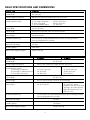
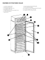
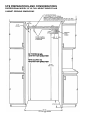
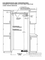
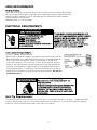
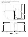
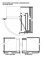
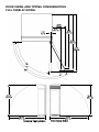
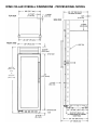
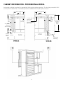
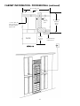
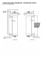
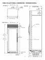
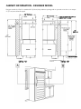
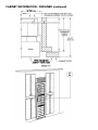
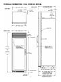
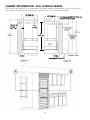
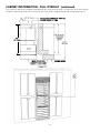
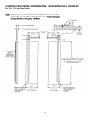
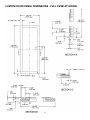
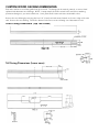
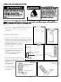
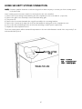
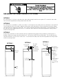
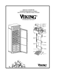
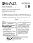
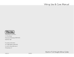
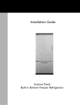
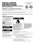
INSTALLATION
INSTRUCTIONS
BUILT-IN FULL HEIGHT WINE CELLAR
VIKING RANGE CORPORATION
111 Front Street
Greenwood, Mississippi 38930 USA
(662) 455-1200
Retain for Future Reference
IMPORTANT - PLEASE READ AND FOLLOW
Make sure that incoming voltage is the same as unit rating. An electric rating plate specifying voltage, frequency, wattage,
amperage, and phase is attached to the product.
To reduce the risk of fire, electric shock, or injury to persons, installation work and electrical wiring must be done by qualified
people in accordance with all applicable codes and standards, including fire-rated construction.
The installer should leave these instructions with the consumer who should retain them for local inspector’s use and for
future reference.
GENERAL INFORMATION
Your safety and the safety of others
is very important.
We have provided many important safety
messages in this manual and on your
appliance. Always read and obey all
safety messages.
This is the safety alert symbol. This
symbol alerts you to hazards that
can kill or hurt you and others.
All safety messages will be
preceded by the safety alert symbol and
the word “DANGER” or “WARNING”.
These words mean:
You will be killed or seriously injured if you
don’t follow instructions.
You can be killed or seriously injured if
you don’t follow instructions.
All safety messages will identify the
hazard, tell you how to reduce the chance
of injury, and tell you what can happen if
the instructions are not followed.
Most of the wine cellar’s weight is at the
top. Extra care is needed when moving
the wine cellar to prevent tipping.
Use cardboard shipping material or
plywood under wine cellar until it is
installed in the operating position to
protect floor surface.
TIP OVER HAZARD
Wine cellar is top heavy and tips easily
when not completely installed.
Keep door closed and shelves in place
until wine cellar is completely installed
per installation instructions.
Use two or more people to move and
install wine cellar.
Failure to do so can result in death or
serious injury.
It is your responsibility to :
-comply with installation specifications and dimensions
-properly install wine cellar
-remove any moldings or decorative panels that prevent the wine cellar
from being serviced
-assure that floor will support wine cellar, door panels and contents
(approximately 1200 lbs. [540 kg]).
-provide a properly grounded electrical outlet
-assure that location will permit appliance doors to open 90o minimum
BASIC SPECIFICATIONS AND DIMENSIONS
DESCRIPTION
VCWB300
Overall Width
30” (76.2 cm)
Overall Height from Bottom
Min. 82 3/4” (210.2 cm) to Max. 84 1/16” (213.5 cm)
Overall Depth from Rear
To rear edge of side trim
To front of top grille
To end of handle bracket
Cutout Width
29 1/2” (74.9 cm)
Cutout Height
82 7/8” (210.5 cm) min.; 84 1/16” (213.5 cm) max.
Cutout Depth
24” (61.0 cm) min.
Electrical Requirements
115 volt, 60 Hz, 15 amp dedicated circuit; 3-wire cord with grounded
3-prong plug attached to product.
Maximum Amp Usage
2.0 amps
Overall Capacity
150 bottles
Approximate Shipping Weight
560 lbs. (252 kg)
DESCRIPTION
22 3/16” (56.4 cm)
24 1/2” (62.2 cm)
27” (68.6 cm)
DDWB300
DFWB300
Overall Width
30” (76.2 cm)
Overall Height from Bottom
Min. 82 3/4” (210.2 cm) to Max. 84 1/16” (213.5 cm)
Overall Depth from Rear
To front edge of side trim
To front edge of cabinet side trim
To front edge of door trim
23 13/16” (60.5 cm)
24” (61.0 cm)
26” (66.0 cm)
Cutout Width
23 13/16” (60.5 cm)
24 3/4” (62.9 cm)
24” (61.0 cm)
30” (76.2 cm)
Cutout Height
82 7/8” (210.5 cm) min.; 84 1/16” (213.5 cm) max.
Cutout Depth
24” (61.0 cm) min.
Electrical Requirements
115 volt, 60 Hz, 15 amp dedicated circuit; 3-wire cord with grounded
3-prong plug attached to product.
25” (63.5 cm) - can be
installed in 24” (61.0 cm) deep
openings; door faces and top
grille will protrude 3/4” (1.9
cm) into room.
Maximum Amp Usage
2.0 amps
Overall Capacity
150 bottles
Approximate Shipping Weight
560 lbs. (252 kg)
2
FEATURES OF YOUR WINE CELLAR
1.
2.
3.
4.
5.
6.
7.
8.
9.
10.
11.
12.
TriTempTM storage system
Electronic control center
Convertible display shelves (2)
Extendable shelves (13)
Energy efficient and UV resistant glass doors
Low intensity lighting
Black interior
8
High temperature alarm (behind grille)
Door alarm (behind grille)
Connection to home security system (behind grille)
Door stop settings - 90o, 110o, 120o
Keyed door lock - (on front of door)
9
10
2
3
4
5
6
1
7
12
11
3
SITE PREPARATIONS AND CONSIDERATIONS
PROFESSIONAL MODEL 30” W. FULL HEIGHT WINE CELLAR
CABINET OPENING DIMENSIONS
84 1/16 (213.5) cm max.
anti-tip board and opening height
82 7/8 min. (210.5 cm)
anti-tip board and opening height
4
SITE PREPARATIONS AND CONSIDERATIONS
DESIGNER/FULL OVERLAY MODEL 30” W. FULL HEIGHT WINE CELLAR
CABINET OPENING DIMENSIONS
84 1/16” (213.5 cm) Max.
anti-tip board and opening height
82 7/8” (210.5 cm) Min.
anti-tip board and opening height
DDWB
DFWB
30” (76.2 cm)
opening
5
24” (61.0 cm)
25” (63.5 cm)*
*Full overlay models fit flush in 25” (63.5
cm) deep cabinet openings. They can be
installed in standard 24” (61.0 cm) deep
openings. The door faces and top grille
will protrude 3/4” (1.9 cm) into the room.
AREA REQUIREMENTS
Verify the following:
•Wine cellar can fit into residence and can be moved around corners and through doorways.
•Floors can support wine cellar’s weight plus wine weight (approximately 1200 pounds total).
•Remove anything attached to rear or side walls that can obstruct wine cellar installation.
•Cutout dimensions are accurate.
•Electrical outlet is in correct location.
ELECTRICAL REQUIREMENTS
ELECTRICAL SHOCK HAZARD
Plug into a grounded 3-prong outlet.
DO NOT remove ground plug.
DO NOT use an adapter.
DO NOT use an extension cord.
Failure to follow these instructions could result in
fire or electrical shock.
If codes permit a separate grounding wire to be
used, it is recommended that a qualified electrician
determine that the grounding path is adequate.
Do Not ground to a gas pipe. Check with a
qualified electrician if you are not sure the
appliance is properly grounded. Do Not have a
fuse in the neutral or grounding circuit.
It is the customer’s responsibility to:
•contact a qualified electrical installer.
•assure that the electrical installation is adequate and in conformance with the
National Electrical Code, ANSI/NFPA 70-latest edition or Canadian Electrical
Code C22.1-1998 and C22.2 No. 0-M91 (or latest edition), and all local
codes and ordinances. (115 volt, 60-Hz, 15 amp, fused, electrical supply is
required. It is required that a separate circuit serving only this appliance be
provided. This appliance is equipped with a power supply cord having a 3prong grounding plug. To minimize possible shock hazard, the cord must be
plugged into a mating 3-prong, grounding-type wall receptacle. Do not use
an extension cord.)
TIP OVER HAZARD
Wine cellar is top heavy and tips easily when not
completely installed.
Keep door closed and shelves in place until wine cellar
is completely installed and secured per installation
instructions. Use two or more people to move and
install wine cellar. Failure to do so can result in death
or serious injury.
Anti-Tip Requirements
The anti-tip boards should be fastened into position prior to moving the unit into the opening. Additional boards
may be required if wine cellar does not touch the back wall of the enclosure. To prevent wine cellar from tipping
forward, it must be secured in place with a solid soffit or wood block.
6
DOOR SWING AND TIPPING CONSIDERATIONS
PROFESSIONAL MODEL
15 1/2”
(39.4 cm)
11 1/2”
(29.2 cm)
2 1/2”
(6.4 cm)
48 5/8”
(123.5 cm)
50 1/2”
(128.2 cm)
51 7/8”
(131.8 cm)
90o
110o
120o
87 1/2
(222.2 cm)
85 1/2
(217.1 cm)
112 1/2
(285.7 cm)
106 1/2
(270.5 cm)
BACKWARD
TIPPING RADIUS
SIDE
TIPPING RADIUS
7
DOOR SWING AND TIPPING CONSIDERATIONS
DESIGNER MODEL
15 3/8”
(39.1 cm)
11 3/8”
(28.9 cm)
2” (5.0 cm)
48 5/8”
(123.5 cm)
50”
(127.0 cm)
51 7/8”
(131.8 cm)
90o
110o
120o
85 1/2”
(217.1 cm)
87 1/2”
(222.2 cm)
112 1/2”
(285.7 cm)
106 1/2”
(270.5 cm)
Side Tipping Radius
Backward Tipping Radius
8
DOOR SWING AND TIPPING CONSIDERATIONS
FULL OVERLAY MODEL
13 3/8”
(34.0 cm)
8 7/8”
(22.5 cm)
1 3/8”
(3.5 cm)
49 3/4”
(128.9 cm)
51 3/8”
(130.5 cm)
52 1/2”
(133.3 cm)
90o
110o
120o
85 1/2”
(217.1 cm)
87 1/2”
(222.2 cm)
106 1/2”
(270.5 cm)
112 1/2”
(285.7 cm)
Side Tipping Radius
Backward Tipping Radius
9
WINE CELLAR OVERALL DIMENSIONS - PROFESSIONAL MODEL
82 7/8”
(210.5 cm)
min.
to
84 1/16”
(213.5 cm)
10
CABINET INFORMATION - PROFESSIONAL MODEL
Professional models fit “semi-flush” in standard 24” (61.0 cm) deep cabinet openings. The door face protrudes 2-5/16”
(5.9 cm) from the cabinet face. The handle protrudes an additional 2-1/2” (6.4 cm) into the room
29 1/2” (90.2 cm)
29 1/2” (90.2 cm)
Wall
Wall
3/4”
(1.9 cm)
Full end
panel
1 13/16”
(4.6 cm)
24” (61.0 cm)
Standard
cabinet depth
2 5/16”
(5.9 cm)
Offset
5/16”
(0.8 cm)
1 13/16” (4.6 cm)
space if 24”
(61.0 cm)
standard cabinet
depth used
3/4”
(1.9 cm)
Full end
panel
DOOR
DOOR
24” (61.0 cm)
Standard
cabinet
depth
2 5/16” (5.9 cm)
Offset
Countertop
Overhang
DETAIL A-A
DETAIL B-B
A-A
B-B
11
CABINET INFORMATION - PROFESSIONAL (continued)
29 1/2” (90.2 cm)
Wall
3/4”
(1.9 cm)
Full end
panel
1 13/16” (4.6 cm)
space if 24” (61.0 cm)
standard cabinet
depth used
DOOR
2 5/16”
(5.9 cm)
Offset
24” (61.0 cm)
Standard
cabinet
depth
Partial Overlay
Cabinet Door
C-C
DETAIL C-C
12
CUSTOM SIDE PANEL DIMENSIONS - PROFESSIONAL MODEL
For 3/4” (1.9 cm) Side Panels
22 3/8”
(56.9 cm)
22 3/8”
(56.9 cm)
82 7/8” (210.5 cm) to
84 1/16” (213.5 cm)
Depending on how
high leveling feet are
raised and cabinet
enclosure height
OPTIONAL KICKPLATE NOTCH DIMENSIONS DETERMINED BY
CABINETS
22 3/16”
(56.4 cm)
22 3/16”
(56.4 cm)
13
OPTIONAL KICKPLATE
NOTCH - DIMENSIONS
DETERMINED BY CABINETS
WINE CELLAR OVERALL DIMENSIONS - DESIGNER MODEL
82 7/8”
(210.5 cm)
min.
to
84 1/16”
(213.5 cm)
max.
14
CABINET INFORMATION - DESIGNER MODEL
Designer models fit “flush” in standard 24” (61.0 cm) deep cabinet openings with no protrusion into the room except
2” (5.1 cm) curved handle depth
30” (76.2 cm)
30” (76.2 cm)
1” (2.5 cm) SPACE IF 25” (63.5 cm)
CABINET DEPTH IS USED
25”
(63.5 cm)
CABINET FRONT
DETAIL “A”
DETAIL “B”
15
CABINET INFORMATION - DESIGNER (continued)
30” (76.2 cm)
WINE CELLAR AND
CABINET DOOR FLUSH
16
OVERALL DIMENSIONS - FULL OVERLAY MODEL
82 7/8”
(210.5 cm)
min.
to
84 1/16”
(213.5 cm)
max.
17
CABINET INFORMATION - FULL OVERLAY MODEL
Full overlay models, (with 3/4” [1.9 cm] thick panels and custom handles locally supplied), fit flush in 25” (63.5 cm)
deep (countertop depth) cabinet openings with no protrusion into room except custom handles.
30” (76.2 cm)
3/4” (1.9 cm)
Full End
Panel
30” (76.2 cm)
1/4” (0.6 cm) SPACE IF 25” (63.5 cm)
CABINET DEPTH IS USED
1/4”
(0.6 cm)
24”
(61.0 cm)
FLUSH
FLUSH
COUNTERTOP DEPTH
18
CABINET INFORMATION - FULL OVERLAY (continued)
Full overlay models can be installed in standard 24” (61.0 cm) deep openings. However, the door faces and top
ventilation grille will protrude 3/4” (1.9 cm) into the room, ideal for alignment with full overlay cabinet doors.
1/4” (0.6 cm) SPACE IF 25” (63.5 cm)
CABINET DEPTH IS USED
24”
(61.0 cm)
WINE CELLAR AND
CABINET DOOR FLUSH
CABINET DOOR
19
CUSTOM SIDE PANEL DIMENSIONS - DESIGNER/FULL OVERLAY
For 3/4” (1.9 cm) Side Panels
NOTE: Adding a 3/4” (1.9 cm) side panel adds an additional 3/4” (1.9 cm) to the
overall width of the product for each side panel used. Requires side panel
hardware kit ( Kit model number - SPHKDS)
82 7/8” (210.5 cm) TO 84 1/16” (213.5cm)
DEPENDING ON HOW HIGH LEVELING
FEET ARE RAISED AND CABINET
ENCLOSURE HEIGHT
20
CUSTOM DOOR PANEL DIMENSIONS - FULL OVERLAY MODEL
21
DOOR PANEL INSTALLATION - FULL OVERLAY MODEL
Panels must not weigh more than 50 pounds per door.
Pre-drill the holes in the panel per the panel dimension instructions. (See panel dimensions for proper hole locations.)
Place the panel onto the door and using 1/2” #8 wood screws, attach the panel in 12 places. (2 at the top and
bottom, 4 on each side) Note: The handle must be attached to the panel prior to installing the panel onto the door.
See panel dimensions for proper attachment locations of the handles.) Use the enclosed adhesive backed mylar pieces
to cover the screws after installation of the panel.
22
CUSTOM WOOD FACINGS DIMENSIONS
Each wine rack has a wood facing which can be removed. The facings can be stained, painted, or removed and
replaced with alternative wood facings. NOTE: A scrap sample should be tested in the unit before attaching
permanent changes to your wine cellar fronts. Some paints and/or stains can cause undesirable odors.
Remove the wood facing by removing the four 1/4” (.6 cm) hex head screws located on the inner edge of the wine
rack. Remove the wood facing. Follow the dimensions below to cut wood facing out of alternative woods.
Short Facing Dimensions (Top Two Zones)
SCALE 1.000
Tall Facing Dimensions (Lower zone)
23
WINE CELLAR INSTALLATION
TIP OVER HAZARD
Wine cellar is top heavy and tips easily
when not completely installed. Keep
door closed and shelves in place until
wine cellar is completely installed and
secured per installation instructions.
Use two or more people to move and
install wine cellar. Failure to do so can
result in death or serious injury.
Use two or more people to move and install
wine cellar. Failure to follow this instruction
can result in back or other injury. To avoid
personal injury, wear gloves when
performing any installation procedure and
wear eye protection when cutting metal
straps.
Most of the wine cellar’s weight is at the top. Extra care is needed when moving the wine cellar to prevent tipping.
Do Not remove protective film until wine cellar is in operating position. All four leveling legs must contact the floor to
support and stabilize the full weight. Do not drop wine cellar.
Figure 1
1. Remove exterior shipping materials prior to moving wine
cellar into home. Remove top and bottom strap
(see Figure 1).
Figure 2
2. Remove top cap (see Figure 1).
3. Cut carton rear approximately 1/4” (.64 cm) to 1” (2.5 cm)
from right corner (see figure 2) with a utility knife extended
1/4” (.6 cm). Remove carton and exterior packaging. Save
cardboard shipping material to protect floor surface when
installing wine cellar. Remove anti-tip
boards and kickplate from rear of wine
cellar (see Figure 3).
4. Remove shipping brackets from skid by
removing 4 bolts (2 each side) with a 1/2”
socket head driver (see Figure 4)
•Tilting wine cellar is not required to
remove shipping brackets.
Figure 3
KICKPLATE
ANTI-TIP BOARDS
5. Slip cart between wine cellar and skid.
Remove wine cellar from skid. Use excess
packaging to protect decorative trim. Verify
that leveling legs are
up (0” adjustment)
(see Figure 5).
6. To avoid floor damage,
use protective material.
(see Figure 6).
BACK VIEW
Figure 4
(4) 1/2” (1.3 cm)
BOLTS
BACK VIEW
Figure 5
Figure 6
PROTECT TRIM FROM
STRAPPING
FRONT LEVELING
LEGS (2)
SKID
24
PROTECT
FLOOR
HOME SECURITY SYSTEM CONNECTION
NOTE: Contact a qualified electrician or authorized agent from alarm company to connect your home security system
to the wine cellar.
Home security system connection must be hooked up before the unit is installed.
1) Remove the four mounting screws attaching the unit compartment cover to the cabinet. (2 per side)
2) Remove the grille louver assembly to access the black safety grille.
3) Turn power off.
4) Remove the four screws that attach the top grille assembly to the mounting brackets.
5) Remove the 3 screws at the right side of the unit that attach the safety grille to the compartment cover.
6) Choose the desired switching position and connect according to alarm system requirements.
7) Replace the unit compartment cover.
The home security system will be activated if temperatures in the wine cellar fluctuate outside of the set point by 5o for
and extended time period.
Red, white, and black
wiring*
*Black = common
Red = normally closed
White = normally open
Back side of wine cellar
25
Electrical Shock Hazard
Disconnect power at breaker or turn power disconnect switch
to OFF position before performing any installation
procedure. Failure to do so can result in death or electrical
shock.
SECURING THE WINE CELLAR (3 OPTIONS)
OPTION 1
If a solid soffit is 1” (2.5 cm) or less above the wine cellar, anti-tip boards are not required. To secure the wine cellar
raise unit until compartment is firmly seated under the soffit.
OPTION 2
If a solid soffit is not available or soffit is more than 1” (2.5 cm) above wine cellar, center wood boards on rear wall 1/4”
(.6 cm) maximum above wine cellar. Attach wood boards to wall studs with six of the provided wood screws, making
sure that screws are engaged in wall studs 1 1/2” (3.8 cm) minimum and that boards extend 2” (5.0 cm) minimum over
the top rear of wine cellar compressor cover. To secure the wine cellar, raise unit until compartment is firmly seated
under the anti-tip board.
OPTION 3
Position the wood block over the unit and secure it to wall studs using eight of the provided wood screws and “L”
brackets. Make sure screws extend a minimum of 1” (2.5 cm) into each of the two wall studs. The wood block must
extend a minimum of 3” (7.6 cm) over the unit. To secure the wine cellar, raise unit until compartment is firmly seated
under the anti-tip boards.
OPTION 3
OPTION 2
OPTION 1
Two 2X4
boards
attached to
wall with six
wood screws
(minimum)
1/4” (.6 cm)
maximum
Solid Soffit
1”
(2.5 cm)
or less
1/4” (.6 cm)
maximum
3” (7.6 cm)
minimum
2” (5.0 cm)
minimum
Rear
wall
26
“L” bracket
with (4) screws
on each end.
(1) 2X4
attached to
both “L”
brackets minimum of
1” (2.5 cm)
screws
Screws extend
minimum of
1” (2.5 cm)
into each wall
stud.
Before moving the wine cellar in place,
confirm the finished dimensions, electrical
location, minimum door and shelf clearances,
and door panel instructions. (See pages 3, 4,
& 5).
1. Position wine cellar in front of
cutout.
2. Verify operation by plugging
power cord in receptacle. Power
switch will be shipped in the
“ON” position and showroom
switch will be in the “OFF”
position. (If showroom switch is
switched to the “ON” position,
showroom mode is engaged and
power is shut-off to the
compressor. This mode is for
showroom display only).
Power “ON/OFF”
switch
Showroom
switch
3. Roll wine cellar into cutout to within 3” (7.6 cm) of being flush with cabinets. To avoid kitchen cabinet damage,
place cardboard between cabinets and wine cellar. Push cardboard back with wine cellar and remove cardboard
when wine cellar is in place.
4. Lift the wine cellar off the rollers, adjust to desired height and level wine cellar by using a 5/16” hex head wrench.
(Refer to Figure at the right)
a) To raise/lower right side rear, rotate the right side rear hex rod.
b) To raise/lower the left side rear, rotate the left
side rear hex rod.
c) To raise/lower the right side front, rotate the
right side front hex rod.
d) To raise/lower the left side front, rotate the left
side front hex rod.
NOTE: DO NOT use an electric driving device.
Overtightening can cause damage.
5. Align wine cellar with sides of cabinets by adjusting
leveling legs. Rotate leveling legs until firmly in
place against floor.
VIEW SHOWN WITH KICKPLATE REMOVED
6. To secure wine cellar, raise unit until compartment
cover is firmly seated under the soffit or anti-tip boards.
7. Open door. Control panel should be lit. Verify the position of the power on/off and showroom switch if there is no
power to wine cellar.
27
KICKPLATE INSTALLATION
The kickplate consists of a two (2) part assembly: one top louvered panel and one bottom solid panel. Install the
kickplate with louvered section on the top. Flooring must allow the kickplate to be removed. See “Site Preparations”
for height clearance (page 3).
To install:
1. Insert the bottom (solid) panel into the open end of the top (louvered) panel. The holes in the bottom panel should
line up with the slots in the top panel.
2. Position the kickplate assembly along the front edge of the wine cellar.
3. Align the holes on both ends of the top (louvered ) panel with the holes in the base of the wine cellar.
4. Attach the kickplate to the wine cellar on each side with the two black phillips head screws provided.
5. Adjust the bottom (solid) panel to the desired height and fasten in place by tightening the screws in the slots.
There is approximately 1” (2.5 cm) of vertical adjustment on the kickplate.
Screws and slots
for adjustments
Attach to unit with these screws
DOOR STOP ADJUSTMENT
1. Using a 3/16” allen wrench, remove door stop pin
located in bottom hinge.
2. The pin is factory set 110o. For 120o swing, move the
pin to the utmost forward stop hole. For 90o swing,
move the pin to the utmost rear stop hole.
HINGE ADJUSTMENT
1. Using a 3/16” allen wrench, remove the door stop
pin located in bottom hinge.
2. Using the height adjustment shim as a wrenching
device, rotate the height adjustment bushing
counterclockwise to raise or clockwise to lower the
location of the door.
3. When proper adjustment is reached, align shim with
door stop pin holes and replace door stop pin.
Firmly tighten pin in place.
90o door stop
28
120o door stop
WIRING DIAGRAM
BUILT-IN FULL HEIGHT WINE CELLAR
29
WIRING SCHEMATIC
BUILT-IN FULL HEIGHT WINE CELLAR
WARNING: ELECTRICAL GROUNDING INSTRUCTIONS
This appliance is equipped with a three prong grounding plug for your protection against shock hazard and should be
plugged directly into a properly grounded three prong receptacle. DO NOT CUT OR REMOVE THE GROUNDING
PRONG FROM THIS PLUG.
REFER ONLY TO FEATURES WHICH ARE EQUIPPED WITH THIS UNIT.
30
31
VIKING RANGE CORPORATION
111 Front Street • Greenwood, Mississippi 38930 USA • (662) 455-1200
Specifications subject to change without notice
www.vikingrange.com
F20383
(PS0905VR)