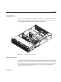
1
SGI® Rackable™ C2108-TY11 System
User’s Guide
007-5782-001
COPYRIGHT
© 2011 SGI. All rights reserved; provided portions may be copyright in third parties, as indicated elsewhere herein. No permission is granted to copy, distribute,
or create derivative works from the contents of this electronic documentation in any manner, in whole or in part, without the prior written permission of SGI.
LIMITED RIGHTS LEGEND
The software described in this document is “commercial computer software” provided with restricted rights (except as to included open/free source) as specified
in the FAR 52.227-19 and/or the DFAR 227.7202, or successive sections. Use beyond license provisions is a violation of worldwide intellectual property laws,
treaties and conventions. This document is provided with limited rights as defined in 52.227-14.
The electronic (software) version of this document was developed at private expense; if acquired under an agreement with the USA government or any
contractor thereto, it is acquired as “commercial computer software” subject to the provisions of its applicable license agreement, as specified in (a) 48 CFR
12.212 of the FAR; or, if acquired for Department of Defense units, (b) 48 CFR 227-7202 of the DoD FAR Supplement; or sections succeeding thereto.
Contractor/manufacturer is SGI, 46600 Landing Parkway, Fremont, CA 94538.
TRADEMARKS AND ATTRIBUTIONS
Silicon Graphics, SGI, and the SGI logo, and Rackable are trademarks or registered trademarks of Silicon Graphics International Corp. in the United States
and/or other countries worldwide.
AMIBIOS is a registered trademark of American Megatrends, Inc. in the United States. InfiniBand is a registered trademark of the InfiniBand Trade
Association. Intel, Itanium, and Xeon are trademarks or registered trademarks of Intel Corporation or its subsidiaries in the United States and other countries.
Internet Explorer and MS-DOS are registered trademarks of Microsoft Corporation. Java and Java Virtual Machine are trademarks or registered trademarks of
Sun Microsystems, Inc. Linux is a registered trademark of Linus Torvalds, used with permission by SGI. MegaRAID and LSI Logic are trademarks or registered
trademarks of LSI Logic Corporation. Novell and Novell Netware are registered trademarks of Novell Inc. PCIe and PCI-X are registered trademarks of PCI
SIG. Red Hat and all Red Hat-based trademarks are trademarks or registered trademarks of Red Hat, Inc. in the United States and other countries. SUSE LINUX
and the SUSE logo are registered trademarks of Novell, Inc. UNIX is a registered trademark in the United States and other countries, licensed exclusively
through X/Open Company, Ltd.
All other trademarks mentioned herein are the property of their respective owners.
Adaptec, HostRAID, and the Adaptec logo are registered trademarks of Adaptec Inc.
Record of Revision
007-5782-001
Version
Description
001
June 2011
Original printing.
iii
Contents
1
2
Record of Revision .
.
.
.
.
.
.
.
.
.
.
.
.
.
.
.
.
.
.
.
.
.
. iii
About This Guide .
.
.
.
.
.
.
.
.
.
.
.
.
.
.
.
.
.
.
.
.
.
.xvii
Introduction
.
.
.
.
.
.
.
.
.
.
.
.
.
.
.
.
.
.
.
.
.
.
1
Server Chassis Features .
.
.
.
.
.
.
.
.
.
.
.
.
.
.
.
.
.
.
.
.
.
3
System Power .
.
.
.
.
.
.
.
.
.
.
.
.
.
.
.
.
.
.
.
.
.
3
Disk Drive Subsystem .
.
.
.
.
.
.
.
.
.
.
.
.
.
.
.
.
.
.
.
.
3
Front Control Panel .
.
.
.
.
.
.
.
.
.
.
.
.
.
.
.
.
.
.
.
.
.
3
Serverboard .
.
.
.
.
.
.
.
.
.
.
.
.
.
.
.
.
.
.
.
.
.
.
.
.
.
3
Cooling System .
.
.
.
.
.
.
.
.
.
.
.
.
.
.
.
.
.
.
.
.
.
.
4
Serverboard Features
.
.
.
.
.
.
.
.
.
.
.
.
.
.
.
.
.
.
.
.
.
.
4
Processors .
.
.
.
.
.
.
.
.
.
.
.
.
.
.
.
.
.
.
.
.
.
.
.
4
Memory .
.
.
.
.
.
.
.
.
.
.
.
.
.
.
.
.
.
.
.
.
.
.
.
4
SATA Controller
.
.
.
.
.
.
.
.
.
.
.
.
.
.
.
.
.
.
.
.
.
.
4
PCI Expansion Slots
.
.
.
.
.
.
.
.
.
.
.
.
.
.
.
.
.
.
.
.
.
4
Onboard Controllers/Ports .
.
.
.
.
.
.
.
.
.
.
.
.
.
.
.
.
.
.
.
5
.
Graphics Controller .
.
.
.
.
.
.
.
.
.
.
.
.
.
.
.
.
.
.
.
.
.
5
Other Features .
.
.
.
.
.
.
.
.
.
.
.
.
.
.
.
.
.
.
.
.
.
.
5
Server Installation .
.
.
.
.
.
.
.
.
.
.
.
.
.
.
.
.
.
.
.
.
.
.
7
Unpack the System .
.
.
.
.
.
.
.
.
.
.
.
.
.
.
.
.
.
.
.
.
.
.
7
Prepare for Setup
.
.
.
.
.
.
.
.
.
.
.
.
.
.
.
.
.
.
.
.
.
.
7
Choose a Setup Location
.
.
.
.
.
.
.
.
.
.
.
.
.
.
.
.
.
.
.
.
7
Warnings and Precautions .
.
.
.
.
.
.
.
.
.
.
.
.
.
.
.
.
.
.
.
.
8
Rack Precautions
007-5782-001
.
.
.
.
.
.
.
.
.
.
.
.
.
.
.
.
.
.
.
.
.
.
.
8
Server Precautions .
.
.
.
.
.
.
.
.
.
.
.
.
.
.
.
.
.
.
.
.
.
9
Rack Mounting Considerations .
.
.
.
.
.
.
.
.
.
.
.
.
.
.
.
.
.
.
.
9
Ambient Operating Temperature .
.
.
.
.
.
.
.
.
.
.
.
.
.
.
.
.
.
9
v
Contents
Reduced Airflow
.
.
.
.
.
.
.
.
.
.
.
.
.
.
.
.
.
.
.
.
.
. 9
Mechanical Loading .
.
.
.
.
.
.
.
.
.
.
.
.
.
.
.
.
.
.
.
.
. 9
Circuit Overloading .
.
.
.
.
.
.
.
.
.
.
.
.
.
.
.
.
.
.
.
.
. 10
Reliable Ground .
.
.
.
.
.
.
.
.
.
.
.
.
.
.
.
.
.
.
.
.
. 10
Install the System into a Rack
.
.
.
.
.
.
.
.
.
.
.
.
.
.
.
.
.
.
.
. 10
Separate the Sections of the Rack Rails .
.
.
.
.
.
.
.
.
.
.
.
.
.
.
.
. 10
Outer Rack Rails.
.
.
.
.
.
.
.
.
.
.
.
.
.
.
.
.
. 12
Install the Outer Rails to the Rack .
.
.
.
.
.
.
.
.
.
.
.
.
.
.
.
.
.
.
.
. 12
.
.
.
.
.
.
.
.
.
.
.
.
.
.
.
.
.
. 12
Install the Inner Rails .
.
.
.
.
.
.
.
.
.
.
.
.
.
.
.
.
.
.
. 12
Install the Server in a Rack .
.
.
.
.
.
.
.
.
.
.
.
.
.
.
.
.
.
.
. 13
.
.
.
.
.
.
.
.
.
.
.
.
.
.
.
.
.
.
. 14
Access the Inside of the Chassis.
.
.
.
.
.
.
.
.
.
.
.
.
.
.
.
.
.
. 14
Check the CPUs (processors)
.
.
.
.
.
.
.
.
.
.
.
.
.
.
.
.
.
.
. 16
Check the System Memory .
.
.
.
.
.
.
.
.
.
.
.
.
.
.
.
.
.
.
. 16
Install Expansion PCI Cards.
.
.
.
.
.
.
.
.
.
.
.
.
.
.
.
.
.
.
.
. 16
Check all Cable Connections and Airflow .
.
.
.
.
.
.
.
.
.
.
.
.
.
.
. 16
Check the Drive Bay Setup .
.
.
.
.
.
.
.
.
.
.
.
.
.
.
.
.
.
. 16
Check the System Disk Drives .
.
.
.
.
.
.
.
.
.
.
.
.
.
.
.
.
. 16
Check the Airflow .
.
.
.
.
.
.
.
.
.
.
.
.
.
.
.
.
.
.
.
.
. 17
Supply Power to the System
.
.
.
.
.
.
.
.
.
.
.
.
.
.
.
.
.
. 17
System Interface.
.
.
.
.
.
.
.
.
.
.
.
.
.
.
.
.
.
.
.
.
.
.
. 19
Overview .
.
.
.
.
.
.
.
.
.
.
.
.
.
.
.
.
.
.
.
.
.
.
. 19
Control Panel Buttons
.
.
.
.
.
.
.
.
.
.
.
.
.
.
.
.
.
.
.
.
.
. 20
.
.
Control Panel LEDs .
.
.
.
.
.
.
.
.
.
.
.
.
.
.
.
.
.
.
.
.
.
. 21
.
.
.
.
.
.
.
.
.
.
.
.
.
.
.
.
.
.
.
.
.
.
. 21
Overheat/Fan Fail
.
.
.
.
.
.
.
.
.
.
.
.
.
.
.
.
.
.
.
.
.
. 21
NIC1 .
.
.
.
.
.
.
.
.
.
.
.
.
.
.
.
.
.
.
.
.
.
.
.
.
. 22
NIC2 .
.
.
.
.
.
.
.
.
.
.
.
.
.
.
.
.
.
.
.
.
.
.
.
.
. 22
HDD .
.
.
.
.
.
.
.
.
.
.
.
.
.
.
.
.
.
.
.
.
.
.
.
.
. 22
Power
.
.
.
.
.
.
.
.
.
.
.
.
.
.
.
.
.
.
.
.
.
.
.
.
. 23
Drive Carrier LEDs .
.
.
.
.
.
.
.
.
.
.
.
.
.
.
.
.
.
.
.
.
.
. 23
Power Fail
vi
.
Install the Inner Rail Extension .
Check the Node Board Setup.
3
.
.
007-5782-001
Contents
4
5
System Safety .
.
.
.
.
.
.
.
.
.
.
.
.
.
.
.
.
.
.
.
.
.
. 25
Electrical Safety Precautions
.
.
.
.
.
.
.
.
.
.
.
.
.
.
.
.
.
.
.
. 25
General Safety Precautions .
.
.
.
.
.
.
.
.
.
.
.
.
.
.
.
.
.
.
.
. 27
ESD Precautions.
.
.
.
.
.
.
.
.
.
.
.
.
.
.
.
.
.
.
.
. 28
.
.
.
.
Advanced Serverboard Setup .
.
.
.
.
.
.
.
.
.
.
.
.
.
.
.
.
.
.
. 29
Handling the Node Board
.
.
.
.
.
.
.
.
.
.
.
.
.
.
.
.
.
.
.
.
. 30
ESD Precautions
.
.
.
.
.
.
.
.
.
.
.
.
.
.
.
.
.
.
.
.
.
. 30
Unpacking .
.
.
.
.
.
.
.
.
.
.
.
.
.
.
.
.
.
.
.
.
.
. 30
.
Connecting the Control Panel .
6
007-5782-001
.
.
.
.
.
.
.
.
.
.
.
.
.
.
.
.
.
. 31
Node Board Details .
.
.
.
.
.
.
.
.
.
.
.
.
.
.
.
.
.
.
.
.
.
. 32
Installing Memory .
.
.
.
.
.
.
.
.
.
.
.
.
.
.
.
.
.
.
.
.
.
. 34
Install DIMMs .
.
.
.
.
.
.
.
.
.
.
.
.
.
.
.
.
.
.
.
.
.
. 34
Memory Configuration .
.
.
.
.
.
.
.
.
.
.
.
.
.
.
.
.
.
.
.
. 38
Memory DIMM Layout
.
.
.
.
.
.
.
.
.
.
.
.
.
.
.
.
.
.
.
. 41
Memory DIMM Rules .
.
.
.
.
.
.
.
.
.
.
.
.
.
.
.
.
.
.
.
. 42
Mismatching Processor and DIMM Speeds
.
.
.
.
.
.
.
.
.
.
.
.
.
.
. 48
Disk Drives (HDDs or SSDs)
.
.
.
.
.
.
.
.
.
.
.
.
.
.
.
.
.
.
.
. 49
PCI Expansion Slots
.
.
.
.
.
.
.
.
.
.
.
.
.
.
.
.
.
.
.
. 50
PCI Cards and RAID Configuration Options .
.
.
.
.
.
.
.
.
.
.
.
.
.
. 50
.
Basic Troubleshooting and Chassis Service .
.
.
.
.
.
.
.
.
.
.
.
.
.
.
. 51
Basic Troubleshooting Procedures .
.
.
.
.
.
.
.
.
.
.
.
.
.
.
. 52
.
.
If the System Does Not Power Up .
.
.
.
.
.
.
.
.
.
.
.
.
.
.
.
.
.
. 52
System Powers Up But Will Not Boot .
.
.
.
.
.
.
.
.
.
.
.
.
.
.
.
. 52
No Video After System Power Up .
.
.
.
.
.
.
.
.
.
.
.
.
.
.
.
.
. 53
Memory Errors .
.
.
.
.
.
.
.
.
.
.
.
.
.
.
.
.
.
. 53
.
.
.
.
Chassis Service Information.
.
.
.
.
.
.
.
.
.
.
.
.
.
.
.
.
.
.
.
. 54
Static-Sensitive Device .
.
.
.
.
.
.
.
.
.
.
.
.
.
.
.
.
.
.
.
.
. 56
Precautions .
.
.
.
.
.
.
.
.
.
.
.
.
.
.
.
.
.
.
.
.
.
.
. 56
Unpacking .
.
.
.
.
.
.
.
.
.
.
.
.
.
.
.
.
.
.
.
.
.
.
. 56
Control Panel
.
.
.
.
.
.
.
.
.
.
.
.
.
.
.
.
.
.
.
.
.
.
.
. 56
System Fans .
.
.
.
.
.
.
.
.
.
.
.
.
.
.
.
.
.
.
.
.
.
.
.
. 57
System Fan Failure .
.
.
.
.
.
.
.
.
.
.
.
.
.
.
.
.
.
.
.
.
. 57
vii
Contents
Replacing System Fans .
.
.
.
.
.
.
.
.
.
.
.
.
.
.
.
.
.
.
.
. 58
Removing a Fan
.
.
.
.
.
.
.
.
.
.
.
.
.
.
.
.
.
.
.
.
. 58
Installing a New Fan
.
.
.
.
.
.
.
.
.
.
.
.
.
.
.
.
.
.
.
. 58
Drive Bay Installation/Removal .
.
.
.
.
.
.
.
.
.
.
.
.
.
.
.
.
.
.
. 58
HDD Drive Installation .
.
.
.
.
.
.
.
.
.
.
.
.
.
.
.
.
.
.
. 58
Installing a Hard Drive into a Carrier .
.
.
.
.
.
.
.
.
.
.
.
.
.
.
. 59
Installing/Removing Hot-swap Drives .
.
.
.
.
.
.
.
.
.
.
.
.
.
.
. 59
Hard Drive Backplane .
.
.
.
.
.
.
.
.
.
.
.
.
.
.
.
.
.
.
.
. 61
DVD-ROM Drive Installation .
.
.
.
.
.
.
.
.
.
.
.
.
.
.
.
.
.
. 61
Accessing the Inside of the Chassis
.
.
.
.
.
.
.
.
.
.
.
.
.
.
.
. 61
.
.
.
.
.
.
.
.
.
.
.
.
.
.
.
. 62
Power Supply.
.
.
.
.
.
.
.
.
.
Power Supply Failure
.
.
.
.
.
.
.
.
.
.
.
.
.
.
.
.
.
.
.
.
. 62
Removing/Replacing the Power Supply.
.
.
.
.
.
.
.
.
.
.
.
.
.
.
.
. 62
Removing the Power Supply
7
BIOS .
.
.
.
.
.
.
.
.
.
.
.
.
.
.
.
.
.
. 62
Installing a New Power Supply.
.
.
.
.
.
.
.
.
.
.
.
.
.
.
.
.
. 62
.
.
.
.
.
.
.
.
.
.
. 63
.
.
.
.
.
.
.
.
.
.
.
.
.
.
.
Starting BIOS Setup Utility .
.
.
.
.
.
.
.
.
.
.
.
.
.
.
.
.
.
.
.
. 63
How To Change the Configuration Data .
.
.
.
.
.
.
.
.
.
.
.
.
.
.
.
.
. 64
Starting the Setup Utility .
.
.
.
.
.
.
.
.
.
.
.
.
.
.
.
.
.
.
.
.
. 64
Main Setup
.
.
.
.
.
.
.
.
.
.
.
.
.
.
.
.
.
.
.
.
. 64
.
.
.
.
System Time/System Update
.
.
.
.
.
.
.
.
.
.
.
.
.
.
.
.
.
.
. 65
Serverboard .
.
.
.
.
.
.
.
.
.
.
.
.
.
.
.
.
.
.
.
.
.
.
. 66
Processor.
.
.
.
.
.
.
.
.
.
.
.
.
.
.
.
.
.
.
.
.
.
.
. 66
System Memory .
.
.
.
.
.
.
.
.
.
.
.
.
.
.
.
.
.
.
.
.
.
. 66
.
Advanced Setup Configurations .
.
.
.
.
.
.
.
.
.
.
.
.
.
.
.
.
.
.
. 67
.
.
.
.
.
.
.
.
.
.
.
.
.
.
.
.
.
.
.
.
.
.
. 68
Quick Boot .
.
.
.
.
.
.
.
.
.
.
.
.
.
.
.
.
.
.
.
.
.
. 68
Quiet Boot .
.
.
.
.
.
.
.
.
.
.
.
.
.
.
.
.
.
.
.
.
.
. 68
Boot Features
viii
AddOn ROM Display Mode
.
.
.
.
.
.
.
.
.
.
.
.
.
.
.
.
.
. 68
Bootup Num-Lock .
.
.
.
.
.
.
.
.
.
.
.
.
.
.
.
.
.
.
.
. 68
Wait For 'F1' If Error
.
.
.
.
.
.
.
.
.
.
.
.
.
.
.
.
.
.
.
. 68
Hit 'Del' Message Display .
.
.
.
.
.
.
.
.
.
.
.
.
.
.
.
.
.
. 68
Interrupt 19 Capture
.
.
.
.
.
.
.
.
.
.
.
.
.
.
.
.
.
. 69
.
.
007-5782-001
Contents
Power Configuration
.
.
.
.
.
.
.
.
.
.
.
.
.
.
.
.
.
.
.
.
. 69
Power Button Function
.
.
.
.
.
.
.
.
.
.
.
.
.
.
.
.
.
.
. 69
Restore on AC Power Loss
.
.
.
.
.
.
.
.
.
.
.
.
.
.
.
.
.
. 69
Watch Dog Timer .
.
.
.
.
.
.
.
.
.
.
.
.
.
.
.
.
.
.
. 69
Processor and Clock Options .
.
.
.
.
.
.
.
.
.
.
.
.
.
.
.
.
.
. 70
Ratio CMOS Setting .
.
.
.
.
.
.
.
.
.
.
.
.
.
.
.
.
.
.
. 70
C1E Support
.
.
.
.
.
.
.
.
.
.
.
.
.
.
.
.
.
.
. 70
Hardware Prefetcher (Available when supported by the CPU)
.
.
.
.
.
.
.
.
.
.
.
.
. 70
Adjacent Cache Line Prefetch (Available when supported by the CPU) .
.
.
.
.
.
. 70
MPS and ACPI MADT Ordering .
.
.
.
.
.
.
.
. 70
Max CPUID Value Limit (Available when supported by the CPU) .
.
.
.
.
.
.
. 71
Intel Virtualization Technology (Available when supported by the CPU)
.
.
.
.
.
.
.
.
.
.
.
.
. 71
Execute-Disable Bit Capability (Available when supported by the OS and the CPU)
.
.
. 71
Simultaneous Multi-Threading (Available when supported by the CPU) .
.
.
.
.
.
. 71
Active Processor Cores
.
.
.
.
.
.
.
.
.
.
.
.
.
.
.
.
.
.
. 71
Intel EIST Technology.
.
.
.
.
.
.
.
.
.
.
.
.
.
.
.
.
.
.
. 71
Intel TurboMode Technology (Available when Intel EIST Technology is enabled) .
.
.
. 72
Intel C-STATE Tech .
.
.
.
.
. 72
C-State package limit setting (Available when Intel® C-State Tech is enabled) .
.
.
.
. 72
C1 Auto Demotion .
.
.
.
.
.
.
.
.
.
.
.
.
.
.
.
.
.
.
.
. 72
C3 Auto Demotion .
.
.
.
.
.
.
.
.
.
.
.
.
.
.
.
.
.
.
.
. 72
Clock Spread Spectrum
.
.
.
.
.
.
.
.
.
.
.
.
.
.
.
.
.
.
. 72
Advanced Chipset Control .
.
.
.
.
.
.
.
.
.
.
.
.
.
.
.
.
.
.
. 73
.
CPU Bridge Configuration.
.
.
.
.
.
.
.
.
.
.
.
.
.
.
.
.
.
.
.
.
.
.
.
.
.
.
.
.
.
.
. 73
.
.
.
.
.
.
.
.
.
.
.
.
.
.
.
.
.
. 75
Crystal Beach/Direct Memory Access (DMA)
.
.
.
.
.
.
.
.
.
.
.
.
. 75
Crystal Beach/ Direct Cache Access (DCA) .
.
.
.
.
.
.
.
.
.
.
.
.
. 75
Payload Size
.
.
.
.
.
.
.
.
.
.
.
.
.
.
.
.
.
.
.
.
.
. 75
Intel VT-d .
.
.
.
.
.
.
.
.
.
.
.
.
.
.
.
.
.
.
.
.
.
. 76
Active State Power Management .
.
.
.
.
.
.
.
.
.
.
.
.
.
.
.
. 76
.
.
.
.
.
.
.
.
.
.
.
.
.
.
.
. 76
North Bridge Configuration
SouthBridge Configuration .
USB Functions .
007-5782-001
.
.
.
.
.
.
.
.
.
.
.
.
.
.
.
.
.
.
.
.
.
.
.
.
.
. 76
Legacy USB Support .
.
.
.
.
.
.
.
.
.
.
.
.
.
.
.
.
.
.
. 76
ix
Contents
I/O Virtualization
.
.
.
.
.
.
.
.
.
.
.
.
.
.
.
.
.
.
.
.
.
. 76
SR-IOV Supported .
.
.
.
.
.
.
.
.
.
.
.
.
.
.
.
.
.
.
.
. 76
IDE and SATA Configuration .
.
.
.
.
.
.
.
.
.
.
.
.
.
.
.
.
.
. 77
SATA#1 Configuration .
.
.
.
.
.
.
.
.
.
.
.
.
.
.
.
.
.
.
. 77
IDE Detect Timeout (sec) .
.
.
.
.
.
.
.
.
.
.
.
.
.
.
.
.
.
. 77
PCI/PnP Configuration .
.
.
.
.
.
.
.
.
.
.
.
.
.
.
.
.
.
.
.
. 78
Clear NVRAM .
.
.
.
.
.
.
.
.
.
.
.
.
.
.
.
.
.
.
.
.
. 78
Plug & Play OS .
.
.
.
.
.
.
.
.
.
.
.
.
.
.
.
.
.
.
.
.
. 78
PCI Latency Timer .
.
.
.
.
.
.
.
.
.
.
.
.
.
.
.
.
.
.
.
. 78
PCI IDE BusMaster.
.
.
.
.
.
.
.
.
.
.
.
.
.
.
.
.
.
.
.
. 78
Slot 1 Option ROM – Slot 7 Option ROM .
.
.
.
.
.
.
.
.
.
.
.
.
.
. 78
LAN1 PXE/LAN2 PXE
.
.
.
.
.
.
.
.
.
.
.
.
.
.
.
.
.
.
. 78
Super IO Device Configuration .
.
.
.
.
.
.
.
.
.
.
.
.
.
.
.
.
.
. 79
Onboard Floppy Controller .
.
.
.
.
.
.
.
.
.
.
.
.
.
.
.
.
.
. 79
Floppy A/Floppy B .
.
.
.
.
.
.
.
.
.
.
.
.
.
.
.
.
.
. 79
Serial Port1 Address/ Serial Port2 Address.
Serial Port 2 Mode .
.
.
.
.
.
.
.
.
.
.
.
.
.
.
. 79
.
.
.
.
.
.
.
.
.
.
.
.
.
.
.
.
.
.
. 79
Remote Access Configuration .
.
.
.
.
.
.
.
.
.
.
.
.
.
.
.
.
.
. 80
.
.
.
.
.
.
.
.
.
.
.
.
.
.
.
.
.
. 80
Remote Access .
.
.
.
Hardware Health Monitor
.
.
.
.
.
.
.
.
.
.
.
.
.
.
.
.
.
.
.
. 81
CPU Overheat Alarm .
.
.
.
.
.
.
.
.
.
.
.
.
.
.
.
.
.
.
. 81
CPU Temperature/System Temperature
.
.
.
.
.
.
.
.
.
.
.
.
.
.
. 82
System Fan Monitor
.
.
.
.
.
.
.
.
.
.
.
.
.
.
. 83
ACPI Configuration .
x
.
.
.
.
.
.
.
.
.
.
.
.
.
.
.
.
.
.
.
.
.
.
.
.
.
.
.
. 84
ACPI Version Features .
.
.
.
.
.
.
.
.
.
.
.
.
.
.
.
.
.
.
. 84
ACPI APIC Support
.
.
.
.
.
.
.
.
.
.
.
.
.
.
.
.
.
.
.
. 84
APIC ACPI SCI IRQ
.
.
.
.
.
.
.
.
.
.
.
.
.
.
.
.
.
.
.
. 84
Headless Mode .
.
.
.
.
.
.
.
.
.
.
.
.
.
.
.
.
.
.
.
.
. 84
NUMA Support .
.
.
.
.
.
.
.
.
.
.
.
.
.
.
.
.
.
.
.
.
. 84
High Performance Event Timer
.
.
.
.
.
.
.
.
.
.
.
.
.
.
.
.
. 84
. 85
IPMI Configuration .
.
.
.
.
.
.
.
.
.
.
.
.
.
.
.
.
.
.
.
.
Status of BMC .
.
.
.
.
.
.
.
.
.
.
.
.
.
.
.
.
.
.
.
.
. 85
IPMI Firmware Revision
.
.
.
.
.
.
.
.
.
.
.
.
.
.
.
.
.
.
. 85
007-5782-001
Contents
View BMC System Event Log .
.
.
.
.
.
.
.
.
.
.
.
.
.
.
.
.
.
. 85
Clear BMC System Event Log.
.
.
.
.
.
.
.
.
.
.
.
.
.
.
.
.
. 86
Set LAN Configuration .
.
.
.
.
.
.
.
.
.
.
.
.
.
.
.
.
.
.
.
. 86
IP Address Configuration .
.
.
.
.
.
.
.
.
.
.
.
.
.
.
.
.
.
.
. 86
Parameter Selector .
.
.
.
.
.
.
.
.
.
.
.
.
.
.
.
.
.
.
.
. 86
IP Address Source .
.
.
.
.
.
.
.
.
.
.
.
.
.
.
.
.
.
.
.
. 86
IP Address .
.
.
.
.
.
.
.
.
.
.
.
.
.
.
.
.
.
.
.
. 87
.
Current IP Address in BMC
.
.
.
.
.
.
.
.
.
.
.
.
.
.
.
.
.
. 87
MAC Address Configuration .
.
.
.
.
.
.
.
.
.
.
.
.
.
.
.
.
.
. 87
Parameter Selector .
.
.
.
.
.
.
.
.
.
.
.
.
.
.
.
.
.
.
.
. 87
Mac Address .
.
.
.
.
.
.
.
.
.
.
.
.
.
.
.
.
.
.
.
. 87
Current Mac Address in BMC .
.
.
.
.
.
.
.
.
.
.
.
.
.
.
.
.
.
. 87
Subnet Mask Configuration
.
.
.
.
.
.
.
.
.
.
.
.
.
.
.
.
.
.
. 88
Parameter Selector .
.
.
.
.
.
.
.
.
.
.
.
.
.
.
.
.
.
.
.
. 88
Subnet Mask
.
.
.
.
.
.
.
.
.
.
.
.
.
.
.
.
.
.
.
.
.
. 88
DMI Event Log .
.
.
.
.
.
.
.
.
.
.
.
.
.
.
.
.
.
.
.
.
.
. 88
View Event Log
.
.
.
.
.
.
.
.
.
.
.
.
.
.
.
.
.
.
.
.
. 88
Mark all events as read.
.
.
.
.
.
.
.
.
.
.
.
.
.
.
.
.
.
.
. 88
Clear event log .
.
.
.
.
.
.
.
.
.
.
.
.
.
.
.
.
.
.
. 88
Security Settings.
.
.
.
.
.
.
.
.
.
.
.
.
.
.
.
.
.
.
.
.
.
.
.
.
. 88
Boot Configuration .
.
.
.
.
.
.
.
.
.
.
.
.
.
.
.
.
.
.
.
.
.
. 91
Boot Device Priority
.
.
.
.
.
.
.
.
.
.
.
.
.
.
.
.
.
.
.
.
. 91
Hard Disk Drives
.
.
.
.
.
.
.
.
.
.
.
.
.
.
.
.
.
.
.
.
. 92
.
Removable Drives .
.
.
.
.
.
.
.
.
.
.
.
.
.
.
.
.
.
.
.
.
. 92
CD/DVD Drives
.
.
.
.
.
.
.
.
.
.
.
.
.
.
.
.
.
.
.
.
.
. 92
.
.
.
.
.
.
.
.
.
.
.
.
.
.
.
.
.
.
.
.
.
. 93
Save Changes and Exit .
.
.
.
.
.
.
.
.
.
.
.
.
.
.
.
.
.
.
.
. 93
Exit Options .
007-5782-001
.
.
.
Discard Changes and Exit .
Discard Changes
.
.
.
.
.
.
.
.
.
.
.
.
.
.
.
.
.
.
. 94
.
.
.
.
.
.
.
.
.
.
.
.
.
.
.
.
.
.
.
.
. 94
Load Optimal Defaults .
.
.
.
.
.
.
.
.
.
.
.
.
.
.
.
.
.
.
.
. 94
Load Fail-Safe Defaults
.
.
.
.
.
.
.
.
.
.
.
.
.
.
.
.
.
.
.
. 94
.
xi
Contents
xii
A
Technical Specifications
.
.
.
.
.
.
.
.
.
.
.
.
.
.
.
.
.
.
.
.
. 95
B
BIOS Error Codes .
.
.
.
.
.
.
.
.
.
.
.
.
.
.
.
.
.
.
.
.
. 97
.
007-5782-001
Figures
007-5782-001
Figure 1-1
SGI Rackable C2108-TY11 Server .
.
.
.
.
.
.
.
.
.
.
1
Figure 1-2
Serverboard Block Diagram .
.
.
.
.
.
.
.
.
.
.
6
Figure 2-1
Separating and Installing the Rack Rails .
.
.
.
.
.
.
.
.
. 11
Figure 2-2
Installing the Server in a Rack
.
.
.
.
.
.
.
.
. 13
Figure 2-3
Accessing the Inside of the System .
.
.
.
.
.
.
.
.
.
. 15
Figure 3-1
Control Panel .
.
.
.
.
.
.
.
.
.
.
.
.
.
.
. 19
Figure 3-2
System Reset Button .
.
.
.
.
.
.
.
.
.
.
.
.
.
. 20
Figure 3-3
System Power On Button
.
.
.
.
.
.
.
.
.
.
.
.
. 20
Figure 3-4
Power Fail LED .
.
.
.
.
.
.
.
.
.
.
.
.
.
. 21
Figure 3-5
Overheat/Fan Fail LED .
.
.
.
.
.
.
.
.
.
.
.
.
. 21
Figure 3-6
LAN1 Network Activity NIC1 LED .
.
.
.
.
.
.
.
.
.
. 22
Figure 3-7
LAN2 Network Activity NIC2 LED .
.
.
.
.
.
.
.
.
.
. 22
Figure 3-8
Hard Drive Activity LED
.
.
.
.
.
.
.
.
.
.
.
.
. 22
Figure 3-9
Power On LED .
.
.
.
.
.
.
.
.
.
.
.
.
. 23
Figure 4-1
Installing the Onboard Battery
.
.
.
.
.
.
.
.
.
.
.
. 26
Figure 5-1
Control Panel Header Pins
.
.
.
.
.
.
.
.
.
.
.
.
. 31
Figure 5-2
Node Board Layout .
.
.
.
.
.
.
.
.
.
.
.
.
.
. 33
Figure 5-3
DIMM Installation
.
.
.
.
.
.
.
.
.
.
.
.
.
. 35
Figure 5-4
Installing DIMM Modules
.
.
.
.
.
.
.
.
.
.
.
.
. 36
Figure 5-5
Removing a DIMM Module .
.
.
.
.
.
.
.
.
.
.
.
. 37
Figure 5-6
Memory DIMM Locations .
.
.
.
.
.
.
.
.
.
.
.
. 39
Figure 5-7
Memory Block Diagram .
.
.
.
.
.
.
.
.
.
.
.
. 41
Figure 5-8
SGI Rackable C2108-TY11 Disk Drive Locations .
.
.
.
.
.
. 49
Figure 5-9
PCI Expansion Slots .
.
.
.
.
.
. 50
.
.
.
.
.
.
.
.
.
.
.
.
.
.
.
.
.
.
.
Figure 6-1
Front Chassis View .
.
.
.
.
.
.
.
.
.
.
.
.
.
. 55
Figure 6-2
Rear Chassic View
.
.
.
.
.
.
.
.
.
.
.
.
.
. 55
Figure 6-3
Removing System Cooling Fans .
.
.
.
.
.
.
.
.
.
.
. 57
Figure 6-4
Mounting a Drive in a Carrier
.
.
.
.
.
.
.
.
.
.
. 59
.
.
xiii
Figures
xiv
Figure 6-5
Removing a Drive Carrier.
.
.
.
.
.
.
.
.
.
. 60
Figure 7-1
System Overview Main BIOS Setup Screen .
.
.
.
.
.
.
.
. 65
Figure 7-2
Advanced Settings Screen
.
.
.
.
.
.
.
. 67
.
.
.
.
.
.
.
.
Figure 7-3
Security Settings Screen .
.
.
.
.
.
.
.
.
.
.
.
.
. 89
Figure 7-4
Boot Settings Screen .
.
.
.
.
.
.
.
.
.
.
.
.
.
. 91
Figure 7-5
Exit Options Screen .
.
.
.
.
.
.
.
.
.
.
.
.
.
. 93
007-5782-001
Tables
Tables
007-5782-001
Table 5-1
Recommended Memory DIMM Configurations .
.
.
.
.
.
.
. 44
Table 5-2
Non-Optimal Memory DIMM Configurations .
.
.
.
.
.
.
. 45
Table A-1
System Specifications
.
.
.
.
.
.
.
.
.
.
.
.
.
. 95
Table B-1
BIOS Error Codes
.
.
.
.
.
.
.
.
.
.
.
.
.
. 97
.
xv
About This Guide
This guide provides an overview of the installation, architecture, general operation, and
descriptions of the major components in the SGI® Rackable™ C2108-TY11 server. It also provides
basic troubleshooting and maintenance information, BIOS information, and important safety and
regulatory specifications.
Audience
This guide is written for owners, installers, system administrators, and users of SGI Rackable
C2108-TY11 computer systems. It is written with the assumption that the reader has a good
working knowledge of computers and computer systems.
Chapter Descriptions
The following topics are covered in this guide:
007-5782-001
•
Chapter 1, “Introduction”
Provides an overview SGI Rackable C2108-TY11 server components.
•
Chapter 2, “Server Installation”
Provides a quick setup checklist to get the SGI Rackable C2108-TY11 operational.
•
Chapter 3, “System Interface”
Describes several LEDs on the control panel as well as others on the disk drive carriers that
keep you constantly informed of the overall status of the system as well as the activity and
health of specific components.
•
Chapter 4, “System Safety”
Provides system safety information.
•
Chapter 5, “Advanced Serverboard Setup”
Provides procedures to install a node board into the SGI Rackable C2108-TY11 chassis,
connect the data and power cables, and install expansion cards.
xvii
About This Guide
xviii
•
Chapter 6, “Basic Troubleshooting and Chassis Service”
Describes some basic steps to troubleshoot your system. Additional sections describe basic
component remove and replace procedures.
•
Chapter 7, “BIOS”
Describes the AMIBIOS Setup Utility for the SGI Rackable C2108-TY11 serverboard.
•
Appendix A, “Technical Specifications,”
Describes system component specifications.
•
Appendix B, “BIOS Error Codes,”
Provides BIOS error code information.
007-5782-001
About This Guide
Related Publications
The following SGI and LSI documents are relevant to the SGI Rackable C2108-TY11 server:
•
MegaRAID® SAS Software User’s Guide, publication number, publication number
860-0488-xxx
•
MegaRAID® 1078-based SAS RAID Controllers User Guide, publication number
860-0489-xxx
•
MegaRAID® 6GB/s SAS RAID Controllers User Guide, publication number 860-0502-xxx
•
LSI Integrated SAS for RAID User’s Guide, publication number 860-0476-xxx
•
SGI Foundation Software Start Here, publication number 007-5641-xxx
•
SGI Performance Suite Start Here, publication number 007-5680-xxx
•
SGI InfiniteStorage series documentation
•
Man pages (online)
You can obtain SGI documentation (as well as the pertinent LSI books), release notes, or man
pages in the following ways:
007-5782-001
•
Refer to the SGI Technical Publications Library at http://docs.sgi.com. Various formats are
available. This library contains the most recent and most comprehensive set of online books,
release notes, man pages, and other information.
•
You can also view man pages by typing man <title> on a command line.
xix
About This Guide
Conventions
The following conventions are used throughout this document:
Convention
Meaning
Command
This fixed-space font denotes literal items such as commands, files,
routines, path names, signals, messages, and programming language
structures.
variable
The italic typeface denotes variable entries and words or concepts being
defined. Italic typeface is also used for book titles.
user input
This bold fixed-space font denotes literal items that the user enters in
interactive sessions. Output is shown in nonbold, fixed-space font.
[]
Brackets enclose optional portions of a command or directive line.
...
Ellipses indicate that a preceding element can be repeated.
man page(x)
Man page section identifiers appear in parentheses after man page names.
GUI element
This font denotes the names of graphical user interface (GUI) elements such
as windows, screens, dialog boxes, menus, toolbars, icons, buttons, boxes,
fields, and lists.
Product Support
SGI provides a comprehensive product support and maintenance program for its products. SGI
also offers services to implement and integrate Linux applications in your environment.
xx
•
Refer to http://www.sgi.com/support/
•
If you are in North America, contact the Technical Assistance Center at
+1 800 800 4SGI or contact your authorized service provider.
•
If you are outside North America, contact the SGI subsidiary or authorized distributor in
your country.
007-5782-001
About This Guide
Reader Comments
If you have comments about the technical accuracy, content, or organization of this document,
contact SGI. Be sure to include the title and document number of the manual with your comments.
(Online, the document number is located in the front matter of the manual. In printed manuals, the
document number is located at the bottom of each page.)
You can contact SGI in any of the following ways:
•
Send e-mail to the following address: [email protected]
•
Contact your customer service representative and ask that an incident be filed in the SGI
incident tracking system.
•
Send mail to the following address:
SGI
Technical Publications
46600 Landing Parkway
Fremont, CA 94538
SGI values your comments and will respond to them promptly.
007-5782-001
xxi
Chapter 1
1. Introduction
The SGI Rackable C2108-TY11 server is a 2U rackmount server (see Figure 1-1). It has two main
subsystems: the 2U server chassis and the dual-processor serverboard.
sgi
Figure 1-1
SGI Rackable C2108-TY11 Server
The server has the following configuration options:
007-5782-001
•
One or two 64-bit Intel® Xeon® processor 5600 series (Westmere-EP) or 5500 series
(Nehalem-EP) processors
•
1 to 18 memory DDR3 DIMMs
•
Four low-profile PCIe x8 Gen 2.0 slots
•
Two low-profile PCIe x16 Gen 2.0 slots
•
One low-profile PCIe x4 Gen 1.0 slot
•
8 hot-swappable SATA/SAS disk drives (HDDs or SSDs)
1
1: Introduction
In addition to the serverboard and chassis, the following hardware components have been included
with the server:
•
One slim DVD-ROM drive (optional)
•
Three 8-cm chassis fans
•
Two passive heatsinks
•
One air shroud
•
SATA and SAS accessories
–
One SAS/SATA backplane
–
One 2-ft. SATA cable
–
Two 35-cm SATA cables
–
Two 40-cm SGPIO cables
–
Two 48-cm SATA cables
–
One 70-cm SATA cable
–
Eight drive carriers
•
One rackmount kit
•
One CD containing drivers and utilities
Important: SGI Rackable server systems may sometimes require driver versions that are not
included in the original operating system release. When required, SGI provides these drivers on
an SGI Driver CD, which may ship with the system, or on the system disk (pre-installed in the
factory). For more information on this topic check with your sales or service representative.
2
007-5782-001
Server Chassis Features
Server Chassis Features
This section describes the main features of the SGI Rackable C2108-TY11 server chassis.
System Power
The SGI Rackable C2108-TY11 server chassis features a redundant 720W power supply
composed of two separate power modules. This power redundancy feature allows you to replace
a failed power supply without shutting down the system.
Disk Drive Subsystem
The SGI Rackable C2108-TY11 server chassis supports up to eight SAS/SATA drives (3 Gb/s or
6 Gb/s). The drives are hot-swappable units and are connected to a backplane that provides power
and control.
Note: The operating system you have installed must support RAID to enable the hot-swap
capability of the disk drives.
Front Control Panel
The control panel on the SGI Rackable C2108-TY11 provides you with system monitoring and
control. LEDs that indicate system power, HDD activity, network activity, system overheat and
power supply failure. A main power button and a system reset button are also included. In
addition, two USB ports and one serial port have been incorporated into the control panel to
provide front side USB and COM port access.
Serverboard
The SGI Rackable C2108-TY11 serverboard fits in a server chassis that is an ATX form factor
chassis designed to be used in a 2U rackmount configuration. See section “Serverboard Features”
on page 4 for an overview.
007-5782-001
3
1: Introduction
Cooling System
The SGI Rackable C2108-TY11 server chassis has an innovative cooling design that includes
three 8-cm hot-plug system cooling fans located in the middle section of the chassis. An air shroud
channels the airflow from the system fans to efficiently cool the processor area of the system. The
power supply module also includes a cooling fan.
Serverboard Features
At the heart of the SGI Rackable C2108-TY11 system is a dual-processor serverboard based on
the Intel 5520 + ICH10R chipset and designed to provide maximum performance. This section
describes the main features of the serverboard. See Figure 1-2.
Processors
The serverboard supports single or dual Intel Xeon 5600/5500 processors.
Memory
The serverboard has eighteen DIMM slots that can support up to 288 GB of 1333/1066/800
registered DDR3 ECC SDRAM (see “Installing Memory” on page 34).
SATA Controller
A SATA controller is integrated into the ICH10R (South Bridge) portion of the chipset to provide
a six-port 3 Gb/s SATA subsystem with RAID 0, 1, 10 , 5 and 6 supported. The disk drives are
hot-swappable units.
Note: The disk drives are hot-swappable units if your operating systems has RAID support.
PCI Expansion Slots
The dual-processor serverboard has four low-profile PCIe 2.0 x8 slots, two low-profile PCIe 2.0
x16 slots, and one low-profile PCIe 2.0 x4 slot (see “PCI Expansion Slots” on page 50)
4
007-5782-001
Serverboard Features
Onboard Controllers/Ports
One onboard ATA/100 connector, which supports IDE hard drives or ATAPI devices. The
color-coded I/O ports include one COM port (an additional COM header is located on the
serverboard), a VGA (monitor) port, two USB 2.0 ports (two additional USB headers and one
Type A port are included on the serverboard), PS/2 mouse and keyboard ports and two gigabit
Ethernet ports.
Graphics Controller
The serverboard features an integrated video controller in the Winbond WPCM450 component.
The controller was designed specifically for servers featuring low power consumption, high
reliability and superior longevity.
Other Features
Other onboard features that promote system health include onboard voltage monitors, a chassis
intrusion header, auto-switching voltage regulators, chassis and CPU overheat sensors, virus
protection and BIOS rescue.
007-5782-001
5
1: Introduction
Figure 1-2
6
Serverboard Block Diagram
007-5782-001
Chapter 2
2. Server Installation
This chapter provides a quick setup checklist to get the SGI Rackable C2108-TY11 operational.
Unpack the System
Inspect the shipping container that the SGI Rackable C2108-TY11 was shipped in and note if it
was damaged in any way. If the server shows damage, file a damage claim with the carrier who
delivered it.
Decide on a suitable location for the rack that supports the weight, power requirements, and
environmental requirements of the SGI Rackable C2108-TY11 server. It should be situated in a
clean, dust-free environment that is well ventilated. Avoid areas where heat, electrical noise, and
electromagnetic fields are generated. Place the server rack near a grounded power outlet. Refer to
“Warnings and Precautions” on page 8.
Prepare for Setup
The shipping container should include two sets of rail assemblies, two rail mounting brackets and
the mounting screws that you will use to install the system into a rack.
Read this section in its entirety before you begin the installation procedure.
Choose a Setup Location
Leave enough clearance in front of the rack to enable you to open the front door completely (~25
inches) and approximately 30 inches of clearance in the back of the rack to allow for sufficient
airflow and ease in servicing.
007-5782-001
7
2: Server Installation
Warnings and Precautions
Rack Precautions
8
!
Warning: The SGI Rackable C2108-TY11 server weighs 57 lbs (26 kg). Always use
!
Warning: Extend the leveling jacks on the bottom of the rack to the floor with the full
!
Warning: Attach stabilizers to the rack in single rack installations. Failure to do so can
!
Warning: Couple racks together in multiple rack installations. Failure to do so can result
!
Warning: Be sure the rack is stable before extending a component from the rack. Failure
!
Warning: Extend only one component at a time. Extending two or more components
proper lifting techniques when your move the server. Always get the assistance of another
qualified person when you install the sever in a location above your shoulders. Failure to do
so may result in serious personal injury or damage to the equipment.
weight of the rack resting on them. Failure to do so can result in serious injury or death.
result in serious injury or death.
in serious injury or death.
to do so can result in serious injury or death.
simultaneously may cause the rack to tip over and result in serious injury or death.
007-5782-001
Rack Mounting Considerations
Server Precautions
•
Review the electrical and general safety precautions.
•
Determine the placement of each component in the rack before you install the rails.
•
Install the heaviest server components in the bottom of the rack first, and then work up.
•
Use a regulating uninterruptible power supply (UPS) to protect the server from power surges
and voltage spikes and to keep your system operating in case of a power failure.
•
Allow the hot-pluggable SAS/SATA drives and power supply modules to cool before
touching them.
•
Always keep the rack’s front door and all panels and components on the servers closed when
not servicing to maintain proper cooling.
Rack Mounting Considerations
Ambient Operating Temperature
If installed in a closed or multi-unit rack assembly, the ambient operating temperature of the rack
environment may be greater than the ambient temperature of the room. Therefore, consideration
should be given to installing the equipment in an environment compatible with the manufacturer’s
maximum rated ambient temperature (35º C or 95º F).
Reduced Airflow
Equipment should be mounted into a rack so that the amount of airflow required for safe operation
is not compromised.
Mechanical Loading
Equipment should be mounted into a rack so that a hazardous condition does not arise due to
uneven mechanical loading.
007-5782-001
9
2: Server Installation
Circuit Overloading
Consideration should be given to the connection of the equipment to the power supply circuitry
and the effect that any possible overloading of circuits might have on overcurrent protection and
power supply wiring. Appropriate consideration of equipment nameplate ratings should be used
when addressing this concern.
Reliable Ground
A reliable ground must be maintained at all times. To ensure this, the rack itself should be
grounded. Particular attention should be given to power supply connections other than the direct
connections to the branch circuit (for example, the use of power strips, and so on).
Install the System into a Rack
This section provides information on installing the SGI Rackable C2108-TY11 into a rack. If the
system has already been mounted into a rack, refer to “Check the Node Board Setup” on page 14.
There are a variety of rack units on the market, which may mean the assembly procedure will
differ slightly. You should also refer to the installation instructions that came with the rack unit
you are using.
Note: This rail will fit a rack between 26" and 33.5" deep.
Separate the Sections of the Rack Rails
The chassis package includes two rail assemblies in the rack mounting kit. Each assembly consists
of two sections: an inner fixed chassis rail that secures directly to the server chassis and an outer
fixed rack rail that secures directly to the rack itself.
To separte the inner and outer rails, perform the following steps:
1.
Locate the rail assembly in the chassis packaging as shown in Figure 2-1.
2. Extend the rail assembly by pulling it outward.
3. Press the quick-release tab
10
007-5782-001
Install the System into a Rack
4. Separate the inner rail from the outer rail assembly.
Rail Assembly
1
Extending the Rails
2
3
QuickRelease Tab
4
Separating the
Inner Rail Extension
7
5
6
Figure 2-1
007-5782-001
Separating and Installing the Rack Rails
11
2: Server Installation
Outer Rack Rails
Outer rails attach to the rack and hold the chassis in place. The outer rails for the chassis extend
between 30 inches and 33 inches.
Install the Outer Rails to the Rack
5. Secure the back end of the outer rail to the rack, using the screws provided (see Figure 2-1).
6. Press the button where the two outer rails are joined to retract the smaller outer rail.
7. Hang the hooks of the rails onto the rack holes and if desired, use screws to secure the front
of the outer rail onto the rack.
8. Repeat steps 1-3 for the remaining outer rail.
Install the Inner Rail Extension
The SGI Rackable C2108-TY11 chassis includes a set of inner rails in two sections: inner rails and
inner rail extensions. The inner rails are pre-attached to the chassis, and do not interfere with
normal use of the chassis if you decide not to use a server rack The inner rail extension is attached
to the inner rail to mount the chassis in the rack.
Install the Inner Rails
Perform the following steps to install the inner rails:
12
1.
Place the inner rail extensions on the side of the chassis aligning the hooks of the chassis
with the rail extension holes. Make sure the extension faces "outward" just like the
pre-attached inner rail.
2.
Slide the extension toward the front of the chassis.
3.
Secure the chassis with 2 screws as illustrated. Repeat steps for the other inner rail
extension.
007-5782-001
Install the System into a Rack
Install the Server in a Rack
!
Warning: The SGI Rackable C2108-TY11 server weighs 57 lbs (26 kg) Always use proper
lifting techniques when your move the server. Always get the assistance of another qualified
person when you install the sever in a location above your shoulders. Failure to do so may
result in serious personal injury or damage to the equipment.
You should now have rails attached to both the server chassis and the rack unit. The next step is
to install the server into the rack (refer to Figure 2-2).
1.
Extend the outer rails as shown in Figure 2-2.
2. Align the inner rails of the chassis with the outer rails on the rack.
3. Slide the inner rails into the outer rails, keeping the pressure even on both sides. When the
chassis has been pushed completely into the rack, it should click into the locked position.
4. Optional screws may be used to secure the to hold the front of the chassis to the rack.
Figure 2-2
007-5782-001
Installing the Server in a Rack
13
2: Server Installation
Check the Node Board Setup
Use the following sections to open the top cover and check that each node board is properly
installed and all the connections have been made.
Access the Inside of the Chassis
1.
Grasp the two handles on either side and pull the unit straight out until it locks (you will hear
a “click”).
2. Depress the two buttons on the top of the chassis to release the top cover as shown in
Figure 2-3.
3. Lift the top cover from the chassis.
Note: To remove the system from the rack completely, depress the locking tabs on the chassis
rails (push the right-side tab down and the left-side tab up) to continue to pull the system out
past the locked position.
14
007-5782-001
Check the Node Board Setup
Figure 2-3
007-5782-001
Accessing the Inside of the System
15
2: Server Installation
Check the CPUs (processors)
You may have one or two processors installed into the serverboard. Each processor needs its own
heatsink.
Check the System Memory
Your server system is shipped with system memory installed. Make sure all DIMMs are fully
seated in their slots. For details on adding system memory, refer to “Installing Memory” on
page 34.
Install Expansion PCI Cards
Refer to “PCI Expansion Slots” on page 50 for details on installing PCI expansion cards.
Check all Cable Connections and Airflow
Make sure all power and data cables are properly connected and not blocking the chassis airflow.
Check the Drive Bay Setup
Next, you should check to make sure the system disk drives and disk drive backplane have been
properly installed and all connections have been made.
Check the System Disk Drives
All drives are accessable from the front of the server. For servicing the DVD-ROM, you will need
to remove the top chassis cover. The hard drives can be installed and removed from the front of
the chassis without removing the top chassis cover. Depending upon your system configuration,
your system may have one or more drives installed. For detailed information about how to install
disk drives, see “Disk Drives (HDDs or SSDs)” on page 49.
If you have more than 4TB of storage, you must create multiple volumes to fully utilize your
RAID disks.
16
007-5782-001
Check the Node Board Setup
Refer to the MegaRAID SAS Software User's Guide, SGI publication number 860-0488-00x and
the MegaRAID 1078-based SAS RAID Controllers User's Guide, SGI publication number
860-0489-00x for more information about configuring your system disks.
A slim DVD-ROM may be preinstalled in your server. Refer to Chapter 6 if you need to install a
DVD-ROM disk drive to the system.
Depending upon your system's configuration, your system may have one or more drives already
installed. If you need to install hard drives, please refer to Chapter 6.
Check the Airflow
Airflow is provided by three hot-swappable 8-cm chassis cooling fans. The system component
layout was carefully designed to direct sufficient cooling airflow to the components that generate
the most heat.
Note: Make sure that all power and data cables have been routed in such a way that they do not
block the airflow generated by the fans.
Supply Power to the System
If necessary, install the system in a rack (refer to “Install the System into a Rack” on page 10), and
connect the power cord from the power supply module into a power strip or power distribution
unit (PDU). SGI also recommends that you use an uninterruptible power supply (UPS) source.
007-5782-001
17
Chapter 3
3. System Interface
Overview
Figure 3-1 shows the control panel on the front of the chassis. There are several LEDs on the
control panel as well as others on the disk drive carriers to keep you constantly informed of the
overall status of the system as well as the activity and health of specific components. There are
also two buttons on the chassis control panel.
2
1
RESET
Power
fail
OH/Fan
fail
Figure 3-1
007-5782-001
ETH1
HD
activity
ETH2
Reset
Power
Power
Control Panel
19
3: System Interface
Control Panel Buttons
There are two buttons located on the front of the chassis: a reset button and a power on/off button.
Use the reset button to reboot the system as shown in Figure 3-2.
Figure 3-2
System Reset Button
Figure 3-3 shows the the main power button, which is used to apply or turn off the main system
power. Turning off system power with this button removes the main power but keeps standby
power supplied to the system.
Figure 3-3
20
System Power On Button
007-5782-001
Control Panel LEDs
Control Panel LEDs
The control panel located on the front of the chassis has several LEDs. These LEDs provide you
with critical information related to different parts of the system. This section explains what each
LED indicates when illuminated and any corrective action you may need to take.
Power Fail
The power fail LED ndicates a power supply module has failed as shown in Figure 3-4. The
second power supply module will take the load and keep the system running but the failed module
will need to be replaced. Refer to Chapter 6 for details on replacing the power supply. This LED
should be off when the system is operating normally.
Figure 3-4
Power Fail LED
Overheat/Fan Fail
When the red overheat/fan LED flashes (shown in Figure 3-5), it indicates a fan failure. When on
continuously it indicates an overheat condition, which may be caused by cables obstructing the
airflow in the system or the ambient room temperature being too warm. Check the routing of
the cables and make sure all fans are present and operating normally. You should also check to
make sure that the chassis covers are installed. This LED will remain flashing or on as long as the
indicated condition exists.
Figure 3-5
007-5782-001
Overheat/Fan Fail LED
21
3: System Interface
NIC1
When flashing, the NIC1 LED indicates network activity on the LAN1 port (see Figure 3-6).
1
Figure 3-6
LAN1 Network Activity NIC1 LED
NIC2
When flashing, the NIC2 LED indicates network activity on the LAN2 port (see Figure 3-7).
2
Figure 3-7
LAN2 Network Activity NIC2 LED
HDD
The HDD LED indicates hard drive drive activity when flashing (see Figure 3-8).
Figure 3-8
22
Hard Drive Activity LED
007-5782-001
Drive Carrier LEDs
Power
The power LED indicates power is being supplied to the system's power supply units is shown in
Figure 3-9. This LED should normally be illuminated when the system is operating.
Figure 3-9
Power On LED
Drive Carrier LEDs
Each drive carrier has two LEDs:
•
Blue: When illuminated, the blue LED on the drive carrier indicates drive activity. A
connection to the backplane enables this LED to blink on and off when that particular drive
is being accessed.
•
Red: The red LED indicates a drive failure. If one of the drives fails, you should be notified
by your system management software.
Refer to “Drive Bay Installation/Removal” on page 58 for instructions on replacing failed drives.
007-5782-001
23
Chapter 4
4. System Safety
This chapter describes basic safety precautions.
Electrical Safety Precautions
Basic electrical safety precautions should be followed to protect yourself from harm and the
SGI Rackable C2108-TY11 system from damage, as follows:
• Be aware of the locations of the power on/off switch on the chassis as well as the room's
emergency power-off switch, disconnection switch or electrical outlet. If an electrical accident
occurs, you can then quickly remove power from the system.
• Do not work alone when working with high voltage components.
• Power should always be disconnected from the system when removing or installing main system
components, such as the serverboard, memory modules and disk drives. When disconnecting
power, you should first power down the operating system first and then unplug the power cords.
The unit has more than one power supply cord. Disconnect two power supply cords before
servicing to avoid electrical shock.
• When working around exposed electrical circuits, another person who is familiar with the
power-off controls should be nearby to switch off the power if necessary.
• Use only one hand when working with powered-on electrical equipment. This is to avoid making
a complete circuit, which will cause electrical shock. Use extreme caution when using metal tools,
which can easily damage any electrical components or circuit boards they come into contact with.
• Do not use mats designed to decrease static electrical discharge as protection from electrical
shock. Instead, use rubber mats that have been specifically designed as electrical insulators.
• The power supply power cords must include a grounding plug and must be plugged into
grounded electrical outlets.
007-5782-001
25
4: System Safety
• Serverboard Battery
!
Caution: There is a danger of explosion if the onboard battery is installed upside down,
which will reverse its polarites (see Figure 4-1). This battery must be replaced only with the
same or an equivalent type recommended by the manufacturer. Dispose of used batteries
according to the manufacturer's instructions.
• DVD-ROM Laser
!
Caution: This server may have come equipped with a DVD-ROM drive. To prevent direct
exposure to the laser beam and hazardous radiation exposure, do not open the enclosure or
use the unit in any unconventional way.
• Mainboard replaceable soldered-in fuses: Self-resetting PTC (Positive Temperature Coefficient)
fuses on the mainboard must be replaced by trained service technicians only. The new fuse must
be the same or equivalent as the one replaced. Contact technical support for details and support.
Lithium battery
Battery holder
Figure 4-1
26
Installing the Onboard Battery
007-5782-001
General Safety Precautions
General Safety Precautions
Follow these rules to ensure general safety:
007-5782-001
•
Keep the area around the SGI Rackable C2108-TY11 system clean and free of clutter.
•
The SGI Rackable C2108-TY11 system weighs approximately 57 lbs (25.9 kg.) when fully
loaded. When lifting the system, two people at either end should lift slowly with their feet
spread out to distribute the weight. Always keep your back straight and lift with your legs.
•
Place the chassis top cover and any system components that have been removed away from
the system or on a table so that they won't accidentally be stepped on.
•
While working on the system, do not wear loose clothing such as neckties and unbuttoned
shirt sleeves, which can come into contact with electrical circuits or be pulled into a cooling
fan.
•
Remove any jewelry or metal objects from your body, which are excellent metal conductors
that can create short circuits and harm you if they come into contact with printed circuit
boards or areas where power is present.
•
After accessing the inside of the system, close the system back up and secure it to the rack
unit with the retention screws after ensuring that all connections have been made.
27
4: System Safety
ESD Precautions
!
Caution: Electrostatic discharge (ESD) is generated by two objects with different electrical
charges coming into contact with each other. An electrical discharge is created to neutralize this
difference, which can damage electronic com ponents and printed circuit boards.
The following measures are generally sufficient to neutralize this difference before contact is
made to protect your equipment from ESD:
28
•
Use a grounded wrist strap designed to prevent static discharge.
•
Keep all components and printed circuit boards (PCBs) in their antistatic bags until ready for
use.
•
Touch a grounded metal object before removing the board from the antistatic bag.
•
Do not let components or PCBs come into contact with your clothing, which may retain a
charge even if you are wearing a wrist strap.
•
Handle a board by its edges only; do not touch its components, peripheral chips, memory
modules or contacts.
•
When handling chips or modules, avoid touching their pins.
•
Put the serverboard and peripherals back into their antistatic bags when not in use.
•
For grounding purposes, make sure your computer chassis provides excellent conductivity
between the power supply, the case, the mounting fasteners and the serverboard.
007-5782-001
Chapter 5
5. Advanced Serverboard Setup
This chapter includes procedures to install a node board into the SGI Rackable C2108-TY11
chassis, connect the data and power cables, and install expansion cards.
A layout and quick reference chart is included in this chapter for your reference. See “Installing
Memory” on page 34.
Note: Some software products are protected with software license keys derived from the
Media Access Control (MAC) Ethernet address. When you replace a node board, the MAC
Ethernet address changes. If you are using such a product, you must request a new license key after
replacing the node board. Contact your local customer support office
http://www.sgi.com/support/supportcenters.html
!
007-5782-001
Caution: Install the chassis cover after you have completed accessing the components inside the
server to maintain proper airflow and cooling for the system.
29
5: Advanced Serverboard Setup
Handling the Node Board
!
Caution: Electrostatic discharge (ESD) can damage electrostatic-sensitive devices inside the
server. Use the ESD precautions described below when you handle printed circuit boards or other
components in the system. The following measures are generally sufficient to protect your
equipment from electric static discharge.
ESD Precautions
•
Use a grounded wrist strap designed to prevent electrostatic discharge.
•
Touch a grounded metal object before removing any board from its antistatic bag.
•
Handle each printed circuit board (PCB) by the edges; do not touch the components,
peripheral chips, memory modules, or gold contacts on the PCB.
•
When handling chips or modules, avoid touching the pins.
•
Place the node board, expansion PCI cards, or other boards and components into antistatic
bags when not in use.
•
Make sure your computer chassis provides a conductive path between the power supply, the
case, the mounting fasteners, and the node board to chassis ground.
Unpacking
!
30
Caution: The node board is shipped in antistatic packaging to avoid electrostatic discharge
damage. Be sure to use ESD precautions when you unpack replacement components for the
server. Failure to do so can result in damage to the equipment.
007-5782-001
Handling the Node Board
Connecting the Control Panel
JF1 contains header pins for various front control panel connectors. See Figure 5-1 for the pin
locations of the various front control panel buttons and LED indicators.
All JF1 wires have been bundled into a single cable to simplify this connection. Make sure the red
wire plugs into pin 1 as marked on the board. The other end connects to the Control Panel PCB
board, located just behind the system status LEDs on the chassis.
20
Ground
NMI
x (Key)
x (Key)
Power On LED
Vcc
HDD LED
Vcc
NIC1 LED
Vcc
NIC2 LED
Vcc
OH/Fan Fail LED
Vcc
Power Fail LED
Vcc
Ground
Reset (Button)
Ground
Power (Button)
2
Figure 5-1
007-5782-001
19
1
Control Panel Header Pins
31
5: Advanced Serverboard Setup
Node Board Details
The 2U SGI Rackable C2108-TY11 chassis has one node board. It can be configured with 1 or 2
processor sockets. When configuring two processors, the following rules apply:
•
Both processor sockets must have identical revisions, core voltage, and bus/core speed.
•
The stepping between the two processors on a node board must be identical.
•
If only one processor is installed, the single processor socket must be installed in the socket
labeled CPU1 (See Figure 5-2). The other socket remains empty.
See Figure 5-2 for the general layout of the node board.
32
007-5782-001
Node Board Details
JPI2C1
PWR I2C
FAN7
CPU
FAN1
FAN6
FAN5
P2 DIMM3A
P2 DIMM3B
JPW1
JPW2
JPW3
JUSB1
P2 DIMM3C
FAN1
P2 DIMM2A
FPCTL
KB/MS
P2 DIMM2B
P2 DIMM2C
CPU1
JF1
VGA
P2 DIMM1B
FAN2
COM1
P2 DIMM1A
PHY
Chip
USB
2/3/4/5
USB0/1
IPMI LAN
P2 DIMM1C
P1 DIMM1C
CPU2
JD1
LAN2
LAN1
P1 DIMM1B
P1 DIMM1A
P1 DIMM2C
AUDIO
Header
P1 DIMM2B
CPU2FAN
7.1HD AUDIO
P1 DIMM2A
P1 DIMM3C
P1 DIMM3B
P1 DIMM3A
Slot7 PCI-E 2.0 x8
CD1
Audio
CTRL
SP1
BMC
Firmware
Slot6 PCI-E 2.0 x16
FAN3
Slot5 PCI-E 2.0 x4 (in x8 Slot)
Intel
JI2C2
1
JI2C1
5520
(NorthBridge)
Slot4 PCI-E 2.0 x8 (in x16 Slot)
Intel
(NorthBridge)
ICH 10R
1
SMBUS1JLPC80
Figure 5-2
007-5782-001
DP4
JL1 JWD1
JP5
JP4
J14 J15
J139USB6/7
1394-1 1394-2
I-SATA5
CNF2
S I/O
COM2
JPG1
JPL1
JUSB4
CNF1
Slot1 PCI-E 2.0 x8
JPT1
ADP5
(SouthBridge)
JPI1
1394
CTRL
I-SATA3 I-SATA1
JUSB5
JUSB2
I-SATA4 I-SATA2
I-SATA0
JWF1
FAN4
Slot2 PCI-E 2.0 x16
BMC Graphics
Memory
IDE
JBT1
5520
Slot3 PCI-E 2.0 x8
BMC
CTRL
FLOPPY
BIOS
Intel
JIDE1
LAN
CTRL
JBAT1
JOH1
Node Board Layout
33
5: Advanced Serverboard Setup
Installing Memory
!
Caution: Exercise extreme care when installing or removing DIMM modules to prevent any
possible damage.
SGI Rackable C2108-TY11 serverboard supports up to 288 GB of DDR3 1333/1066/800
registered ECC SDRAM in 18 DIMM slots. Three-way interleaved memory is supported. For
optimal memory performance, install DIMMs three at a time. Use memory modules of the same
type and speed. See the following table for memory installation.
Install DIMMs
Perform the following steps to install memory modules, as follows:
1.
Insert the DIMM module vertically and press down into its slot until it snaps into place. Pay
attention to the alignnment notch at the bottom of the module to avoid installing incorrectly
(see Figure 5-3 and Figure 5-4). Insert the desired number of DIMMs into the memory slots,
beginning with DIMM #1A and DIMM #2A, then DIMM #3A and DIMM #4A, etc. (see
Table 5-1). Always spread DIMMs across all three banks for each CPU (see Figure 5-2).
Gently press down on the DIMM module until it snaps into place in the slot. Repeat for all
modules.
2. To remove a DIMM module, use your thumbs to gently push the release tabs near both ends
of the module (see Figure 5-3). This should release it from the slot (see Figure 5-5).
34
007-5782-001
Installing Memory
1
Front view
Notch
Notch
2
Release tab
Release tab
Top view of DDR3 slot
Figure 5-3
007-5782-001
DIMM Installation
35
5: Advanced Serverboard Setup
Figure 5-4
36
Installing DIMM Modules
007-5782-001
Installing Memory
Figure 5-5
007-5782-001
Removing a DIMM Module
37
5: Advanced Serverboard Setup
Memory Configuration
There are a maximum of eighteen memory DIMMs slots on each node board. Each processor has
three memory channels and maximum performance is achieved when these three channels are
balanced on each processor. It is also important that both processors have the identical memory
configuration.
For maximum memory performance:
•
The memory DIMMs slots must be populated in groups of three, six, or nine on each
processor socket.
•
DIMM configuration should be identical on both processor sockets on a node board.
Configuring node boards with DIMM configuration other than described above will result in
degraded memory performance.
See Figure 5-6 for memory DIMM locations.
38
007-5782-001
P2 DIMM-3B
P2 DIMM-3C
P2 DIMM-2A
P2 DIMM-2B
P2 DIMM-2C
P2 DIMM-1B
P2 DIMM-1C
CPU2
Figure 5-6
007-5782-001
CPU1
P2 DIMM-1A
J108 J107 J106 J105 J104 J103 J102 J101 J100
J110 J111 J112 J113 J114 J115 J116 J117 J118
P2 DIMM-3A
P1 DIMM1C
P1 DIMM1B
Front of Chassis
Rear of Chassis
Installing Memory
P1 DIMM1A
P1 DIMM2C
P1 DIMM2B
P1 DIMM2A
P1 DIMM3C
P1 DIMM3B
P1 DIMM3A
Memory DIMM Locations
39
5: Advanced Serverboard Setup
For blades configured with two processor sockets, install the memory DIMMs in the following
order:
•
•
•
6 DIMMs = Install DIMMs:
•
P1 DIMM 1A, P1 DIMM 2A, and P1 DIMM 3A
•
P2 DIMM 1A, P2 DIMM 2A, and P2 DIMM 3A
12 DIMMs = Install the above six then install the following six DIMMs:
•
P1 DIMM 1B, P1 DIMM 2B, and P1 DIMM 3B
•
P2 DIMM 1B, P2 DIMM 2B, and P2 DIMM 3B
18 DIMMs = Install the above twelve then install the following six DIMMs:
•
P1 DIMM 1C, P1 DIMM 2C, and P1 DIMM 3C
•
P2 DIMM 1C, P2 DIMM 2C, and P2 DIMM 3C
•
For blades configured with one processor socket, install the memory DIMMs in the following
order:
•
3 DIMMs = Install DIMMs:
•
•
6 DIMMs = Install the above three then install the following three DIMMs:
•
•
P1 DIMM 1B, P1 DIMM 2B, and P1 DIMM 3B
9 DIMMs = Install the above six then install the following three DIMMs:
•
40
P1 DIMM 1A, P1 DIMM 2A, and P1 DIMM 3A
P1 DIMM 1C, P1 DIMM 2C, and P1 DIMM 3C
007-5782-001
Installing Memory
Memory DIMM Layout
Figure 5-7
007-5782-001
D
D
R
3
D
D
R
3
D
D
R
3
Memory
Channel 2
D
D
R
3
D
D
R
3
D
D
R
3
Memory
Channel 3
D
D
R
3
D
D
R
3
D
D
R
3
Slot B
Slot A
Intel
5500 or 5600
series processor
Memory
Channel 1
Slot C
The processor memory controller has three channels with three memory DIMM slots on each
channel.
Memory Block Diagram
41
5: Advanced Serverboard Setup
Memory DIMM Rules
Use the following rules when installing memory DIMMs:
42
•
Minimum Number of DIMMs—A minimum of one DIMM on each processor must always
be installed.
•
Slot Order—For each memory channel, populate the DIMM slot that is furthest from the
processor first.
•
Channel Balancing—For best performance, populate each channel with the same number
of identical DIMMs.
•
Mixing DIMM Speeds—All DIMMs populated on all channels on both processors should
be able to support the highest frequency, because the timings of the slowest DIMM will be
applied to all DIMMs.
•
Mixing DIMM Sizes—When mixing DIMMs on a channel that have a mixed number of
ranks, it is recommended to have the total number of ranks on the channel be even to avoid
bandwidth degradation. Example: placing a single-rank DIMM and a dual-rank DIMM on
the same channel is not desirable. The total number of ranks would be three, an odd number
of ranks. If mixing is unavoidable, then DIMMs with the most ranks need to be populated in
the slots farthest from the processor (the “A” slots).
•
Maximum Memory Performance —The DIMMs within a node must be identical in speed
and rank:
–
Speed—1066 or 1333 M transfers/sec (MT/s)
–
Number of ranks —1, 2, or 4
•
Single-processor Node Board
Only Processor 2 is installed in a single processor node board. Only install DIMMs in the P2
DIMM slots. Follow the Processor 2 section of Table 5-1 and Table 5-2 for installing
DIMMs.
•
Minimum Compute Blade Memory Size:
There is 4GB compute blade minimum in systems running SGI Management Center
software.
007-5782-001
Installing Memory
Note 1: Manufacturing does not mix DIMM vendors on a node board. If DIMM vendor A is
installed on a node board, all DIMMs installed on that node board will be from DIMM vendor A.
Different node boards can have different DIMM vendors. Boards with mixed DIMM vendors have
been tested without problems.
Note 2: The speed of the memory controller will reduce to the lowest speed DIMM on the
channel.
Note 3: Nehalem Processors Only—The maximum speed of the memory controller changes
based on the number of DIMMs placed on the channel:
•
With three DIMMs on the channel, the maximum speed supported is 800 MT/s.
•
With two DIMMs on the channel, the maximum speed supported is 1066 MT/s.
•
With one DIMM on the channel, the maximum speed supported is 1333 MT/s.
Note 4: Westmere Processors Only—The maximum speed on the memory controller is reduced
when three DIMMs are placed on a channel:
•
With one or two DIMMs on the channel, the maximum speed supported is 1333 MT/s.
•
With three DIMMs on the channel, the maximum speed supported is 800 MT/s.
See Table 5-1 for the recommended DIMM configurations that will achieve the maximum
memory performance.
Memory DIMM configurations that are described in Table 5-2 will run with degraded
performance.
Note: The minimum compute blade memory size is 4GB. The minimum compute memory size
is 8GB if the compute blade is in a system running SGI Management Center software.
007-5782-001
43
5: Advanced Serverboard Setup
Table 5-1
Recommended Memory DIMM Configurations
Processor 1
44
Processor 2
Channel 1
Channel 2
Channel 3
Channel 1
Channel 2
Channel 3
1A: 2GB
2A: 2GB
3A: 2GB
1A: 2GB
2A: 2GB
3A: 2GB
1B: none
2B: none
3B: none
1B: none
2B: none
3B: none
1C: none
2C: none
3C: none
1C: none
2C: none
3C: none
1A: 2GB
2A: 2GB
3A: 2GB
1A: 2GB
2A: 2GB
3A: 2GB
1B: 2GB
2B: 2GB
3B: 2GB
1B: 2GB
2B: 2GB
3B: 2GB
1C: none
2C: none
3C: none
1C: none
2C: none
3C: none
1A: 4GB
2A: 4GB
3A: 4GB
1A: 4GB
2A: 4GB
3A: 4GB
1B: none
2B: none
3B: none
1B: none
2B: none
3B: none
1C: none
2C: none
3C: none
1C: none
2C: none
3C: none
1A: 2GB
2A: 2GB
3A: 2GB
1A: 2GB
2A: 2GB
3A: 2GB
1B: 2GB
2B: 2GB
3B: 2GB
1B: 2GB
2B: 2GB
3B: 2GB
1C: 2GB
2C: 2GB
3C: 2GB
1C: 2GB
2C: 2GB
3C: 2GB
1A: 4GB
2A: 4GB
3A: 4GB
1A: 4GB
2A: 4GB
3A: 4GB
1B: 4GB
2B: 4GB
3B: 4GB
1B: 4GB
2B: 4GB
3B: 4GB
1C: none
2C: none
3C: none
1C: none
2C: none
3C: none
1A: 8GB
2A: 8GB
3A: 8GB
1A: 8GB
2A: 8GB
3A: 8GB
1B: none
2B: none
3B: none
1B: none
2B: none
3B: none
1C: none
2C: none
3C: none
1C: none
2C: none
3C: none
1A: 4GB
2A: 4GB
3A: 4GB
1A: 4GB
2A: 4GB
3A: 4GB
1B: 4GB
2B: 4GB
3B: 4GB
1B: 4GB
2B: 4GB
3B: 4GB
1C: 4GB
2C: 4GB
3C: 4GB
1C: 4GB
2C: 4GB
3C: 4GB
1A: 8GB
2A: 8GB
3A: 8GB
1A: 8GB
2A: 8GB
3A: 8GB
1B: 8GB
2B: 8GB
3B: 8GB
1B: 8GB
2B: 8GB
3B: 8GB
1C: none
2C: none
3C: none
1C: none
2C: none
3C: none
1A: 8GB
2A: 8GB
3A: 8GB
1A: 8GB
2A: 8GB
3A: 8GB
1B: 8GB
2B: 8GB
3B: 8GB
1B: 8GB
2B: 8GB
3B: 8GB
1C: 8GB
2C: 8GB
3C: 8GB
1C: 8GB
2C: 8GB
3C: 8GB
Memory/
Core
Total
Node
Memory
Size
Maximum
Mem
Speed
(MT/s)
1.5 GB/core
12 GB
1333
3 GB/core
24 GB
1066
3 GB/core
24 GB
1333
4.5 GB/core
36 GB
800
6 GB/core
48 GB
1066
6 GB/core
48 GB
1333
9 GB/core
72 GB
800
12 GB/core
96 GB
1066
18 GB/core
144 GB
800
007-5782-001
Installing Memory
Table 5-1
Recommended Memory DIMM Configurations (continued)
Processor 1
Processor 2
Channel 1
Channel 2
Channel 3
Channel 1
Channel 2
Channel 3
1A: 8GB
2A: 8GB
3A: 8GB
1A: 8GB
2A: 8GB
3A: 8GB
1B: 4GB
2B: 4GB
3B: 4GB
1B: 4GB
2B: 4GB
3B: 4GB
1C: none
2C: none
3C: none
1C: none
2C: none
3C: none
1A: 8GB
2A: 8GB
3A: 8GB
1A: 8GB
2A: 8GB
3A: 8GB
1B: 4GB
2B: 4GB
3B: 4GB
1B: 4GB
2B: 4GB
3B: 4GB
1C: 4GB
2C: 4GB
3C: 4GB
1C: 4GB
2C: 4GB
3C: 4GB
1A: 8GB
2A: 8GB
3A: 8GB
1A: 8GB
2A: 8GB
3A: 8GB
1B: 8GB
2B: 8GB
3B: 8GB
1B: 8GB
2B: 8GB
3B: 8GB
1C: 4GB
2C: 4GB
3C: 4GB
1C: 4GB
2C: 4GB
3C: 4GB
Table 5-2
Total
Node
Memory
Size
Maximum
Mem
Speed
(MT/s)
9 GB/core
72 GB
1066
12 GB/core
96 GB
800
15 GB/core
120 GB
800
Memory/
Core
Total
Node
Memory
Size
Maximum
Mem
Speed
(MT/s)
0.5 GB/core
4 GB
1333
1 GB/core
8 GB
1333
2 GB/core
16 GB
1066
2.5 GB/core
20 GB
1066
3.5 GB/core
28 GB
800
Non-Optimal Memory DIMM Configurations
Processor 1
Processor 2
Channel 1
Channel 2
Channel 3
Channel 1
Channel 2
Channel 3
1A: 2GB
2A: none
3A: none
1A: 2GB
2A: none
3A: none
1B: none
2B: none
3B: none
1B: none
2B: none
3B: none
1C: none
2C: none
3C: none
1C: none
2C: none
3C: none
1A: 2GB
2A: 2GB
3A: none
1A: 2GB
2A: 2GB
3A: none
1B: none
2B: none
3B: none
1B: none
2B: none
3B: none
1C: none
2C: none
3C: none
1C: none
2C: none
3C: none
1A: 2GB
2A: 2GB
3A: 2GB
1A: 2GB
2A: 2GB
3A: 2GB
1B: 2GB
2B: none
3B: none
1B: 2GB
2B: none
3B: none
1C: none
2C: none
3C: none
1C: none
2C: none
3C: none
1A: 2GB
2A: 2GB
3A: 2GB
1A: 2GB
2A: 2GB
3A: 2GB
1B: 2GB
2B: 2GB
3B: none
1B: 2GB
2B: 2GB
3B: none
1C: none
2C: none
3C: none
1C: none
2C: none
3C: none
1A: 2GB
2A: 2GB
3A: 2GB
1A: 2GB
2A: 2GB
3A: 2GB
1B: 2GB
2B: 2GB
3B: 2GB
1B: 2GB
2B: 2GB
3B: 2GB
1C: 2GB
2C: none
3C: none
1C: 2GB
2C: none
3C: none
007-5782-001
Memory/
Core
45
5: Advanced Serverboard Setup
Table 5-2
Non-Optimal Memory DIMM Configurations (continued)
Processor 1
46
Processor 2
Channel 1
Channel 2
Channel 3
Channel 1
Channel 2
Channel 3
1A: 2GB
2A: 2GB
3A: 2GB
1A: 2GB
2A: 2GB
3A: 2GB
1B: 2GB
2B: 2GB
3B: 2GB
1B: 2GB
2B: 2GB
3B: 2GB
1C: 2GB
2C: 2GB
3C: none
1C: 2GB
2C: 2GB
3C: none
1A: 4GB
2A: none
3A: none
1A: 4GB
2A: none
3A: none
1B: none
2B: none
3B: none
1B: none
2B: none
3B: none
1C: none
2C: none
3C: none
1C: none
2C: none
3C: none
1A: 4GB
2A: 4GB
3A: none
1A: 4GB
2A: 4GB
3A: none
1B: none
2B: none
3B: none
1B: none
2B: none
3B: none
1C: none
2C: none
3C: none
1C: none
2C: none
3C: none
1A: 4GB
2A: 4GB
3A: 4GB
1A: 4GB
2A: 4GB
3A: 4GB
1B: 4GB
2B: none
3B: none
1B: 4GB
2B: none
3B: none
1C: none
2C: none
3C: none
1C: none
2C: none
3C: none
1A: 4GB
2A: 4GB
3A: 4GB
1A: 4GB
2A: 4GB
3A: 4GB
1B: 4GB
2B: 4GB
3B: none
1B: 4GB
2B: 4GB
3B: none
1C: none
2C: none
3C: none
1C: none
2C: none
3C: none
1A: 4GB
2A: 4GB
3A: 4GB
1A: 4GB
2A: 4GB
3A: 4GB
1B: 4GB
2B: 4GB
3B: 4GB
1B: 4GB
2B: 4GB
3B: 4GB
1C: 4GB
2C: none
3C: none
1C: 4GB
2C: none
3C: none
1A: 4GB
2A: 4GB
3A: 4GB
1A: 4GB
2A: 4GB
3A: 4GB
1B: 4GB
2B: 4GB
3B: 4GB
1B: 4GB
2B: 4GB
3B: 4GB
1C: 4GB
2C: 4GB
3C: none
1C: 4GB
2C: 4GB
3C: none
1A: 8GB
2A: none
3A: none
1A: 8GB
2A: none
3A: none
1B: none
2B: none
3B: none
1B: none
2B: none
3B: none
1C: none
2C: none
3C: none
1C: none
2C: none
3C: none
1A: 8GB
2A: 8GB
3A: none
1A: 8GB
2A: 8GB
3A: none
1B: none
2B: none
3B: none
1B: none
2B: none
3B: none
1C: none
2C: none
3C: none
1C: none
2C: none
3C: none
Memory/
Core
Total
Node
Memory
Size
Maximum
Mem
Speed
(MT/s)
4 GB/core
32 GB
800
1 GB/core
8 GB
1333
2 GB/core
16 GB
1333
4 GB/core
32 GB
1066
5 GB/core
40 GB
1066
7 GB/core
56 GB
800
8 GB/core
64 GB
800
2 GB/core
16 GB
1333
4 GB/core
32 GB
1333
007-5782-001
Installing Memory
Table 5-2
Non-Optimal Memory DIMM Configurations (continued)
Processor 1
Processor 2
Channel 1
Channel 2
Channel 3
Channel 1
Channel 2
Channel 3
1A: 8GB
2A: 8GB
3A: 8GB
1A: 8GB
2A: 8GB
3A: 8GB
1B: 8GB
2B: none
3B: none
1B: 8GB
2B: none
3B: none
1C: none
2C: none
3C: none
1C: none
2C: none
3C: none
1A: 8GB
2A: 8GB
3A: 8GB
1A: 8GB
2A: 8GB
3A: 8GB
1B: 8GB
2B: 8GB
3B: none
1B: 8GB
2B: 8GB
3B: none
1C: none
2C: none
3C: none
1C: none
2C: none
3C: none
1A: 8GB
2A: 8GB
3A: 8GB
1A: 8GB
2A: 8GB
3A: 8GB
1B: 8GB
2B: 8GB
3B: 8GB
1B: 8GB
2B: 8GB
3B: 8GB
1C: 8GB
2C: none
3C: none
1C: 8GB
2C: none
3C: none
1A: 8GB
2A: 8GB
3A: 8GB
1A: 8GB
2A: 8GB
3A: 8GB
1B: 8GB
2B: 8GB
3B: 8GB
1B: 8GB
2B: 8GB
3B: 8GB
1C: 8GB
2C: 8GB
3C: none
1C: 8GB
2C: 8GB
3C: none
1A: 8GB
2A: 8GB
3A: 8GB
1A: 8GB
2A: 8GB
3A: 8GB
1B: 8GB
2B: 8GB
3B: 8GB
1B: 8GB
2B: 8GB
3B: 8GB
1C: 8GB
2C: 8GB
3C: 8GB
1C: 8GB
2C: 8GB
3C: 8GB
007-5782-001
Memory/
Core
Total
Node
Memory
Size
Maximum
Mem
Speed
(MT/s)
8 GB/core
64 GB
1066
10 GB/core
80 GB
1066
14 GB/core
112 GB
800
16 GB/core
128 GB
800
18 GB/core
144 GB
800
47
5: Advanced Serverboard Setup
Mismatching Processor and DIMM Speeds
The processor is rated for the maximum DIMM speed that it will support. Configuring memory
DIMMs that have a DIMM speed that is greater than the processor capability will result in the
memory DIMM running at the maximum speed of the processor—not the maximum speed of the
DIMM.
Three conditions must be met to have a memory speed of 1333 MT/s:
•
The processor must be capable of supporting (1333 MT/s) / 2.
•
The DIMM must be capable of running at 1333 MT/s.
•
For Nehalem processors, only one DIMM is placed on each channel. Westmere processors
can support two DIMMs on each channel.
Placing three DIMMs on the channel will cause the DIMMs to run at 800 MT/s for both Nehalem
and Westmere processors.
48
007-5782-001
Disk Drives (HDDs or SSDs)
Disk Drives (HDDs or SSDs)
The 2U chassis supports a maximum of eight SAS or SATA disk drives. Install the drives from
left to right. Note: All disk drive bays must be populated to maintain system thermals. Drive bays
must either have a disk drive or a drive blank installed.
RESET
COMPACT
Drive 4
Drive 5
Drive 6
Drive 7
Drive 0
Drive 1
Drive 2
Drive 3
Figure 5-8
SGI Rackable C2108-TY11 Disk Drive Locations
The supported disk drive configurations are as follows:
007-5782-001
•
JBOD
Supports any number of drives between one and eight. The operating system is placed on the
disk drive in location 0. All other drives are data drives.
•
RAID 0 (disk striping without parity)
Supports any number of drives between two and eight. Note: all drives must be the same
type. The operating system will be striped across all drives in the system. This configuration
is not recommended.
•
RAID 1 (disk mirroring)
Supports exactly two drives. The two drives represents one RAID 1 logical drive. The
operating system will be installed on the drives located in Drive 0 and 1. Note: Both drives
must be the same type.
•
RAID 5 (disk striping with parity)
Supports a minimum of three drives and a maximum of eight drives. Possible configurations
are 2+1, 3+1, 4+1, 5+1, 6+1 and 7+1. The operating system will be striped across all drives
in the system. Note: all drives must be the same type.
•
RAID 6 (disk striping with dual parity)
Supports a minimum of four drives and a maximum of eight drives. The operating system
will be striped across all drives in the system. Note: all drives must be the same type.
•
RAID 10 (mirrored disk striping)
The data is striped across one set of drives and then mirrored on another set of drives. A
minimum of four drives of the same type are required.The total number of drives must be an
even number (4, 6, 8). A total of four drives is a 2+2, six drives is a 3+3, and eight drives is a
49
5: Advanced Serverboard Setup
4+4. The operating system will be striped across all drives in the primary set and then
mirrored on the secondary set of drives. Note: all drives must be the same type.
PCI Expansion Slots
There are seven PCI slot bays in the rear of the chassis. The PCI slots are located at the right rear
of the chassis. The slots are numbered from right to left (1 – 7). All of the slots support only
low-profile PCI cards. The following PCI slots are available:
•
Two PCIe x16 Gen 2.0 card slots (slots 2 and 6)
•
Four PCIe x8 Gen 2.0 card slots (slots 1, 3, 4, and 7)
•
One PCIe x4 Gen 2.0 card slot (Slot 5 is dedicated to the system RAID card.)
Slot 1
Slot 2
Slot 3
Slot 4
Slot 5
Slot 6
Slot 7
See Figure 5-9 for slot locations in the rear of the chassis.
PCIe slots
Figure 5-9
PCI Expansion Slots
PCI Cards and RAID Configuration Options
Configuration options for PCI cards include support for 3 Gb/s or 6 Gb/s SAS/SATA RAID
channels and support for the various RAID levels described in section “Disk Drives (HDDs or
SSDs)” on page 49.
50
007-5782-001
Chapter 6
6. Basic Troubleshooting and Chassis Service
Use the procedures in the first half of this chapter to troubleshoot your system:
•
“If the System Does Not Power Up” on page 52
•
“System Powers Up But Will Not Boot” on page 52
•
“No Video After System Power Up” on page 53
•
“Memory Errors” on page 53
If you follow all of the prescribed procedures and still need assistance, check with your authorized
support organization.
The sections following “Chassis Service Information” on page 54 are intended to guide you
through basic component remove and replace procedures:
007-5782-001
•
“Control Panel” on page 56
•
“System Fans” on page 57
•
“Drive Bay Installation/Removal” on page 58
•
“Power Supply” on page 62
51
6: Basic Troubleshooting and Chassis Service
Basic Troubleshooting Procedures
Use the information in the following subsections to remedy basic problems you might encounter
when working with the server.
If the System Does Not Power Up
If the system will not power up when the front power button is pushed, use the following checklist
to identify common sources for the problem:
•
Make sure that both ends of each system power cable are firmly connected to the power
supply and the corresponding power source(s) or power distribution unit (PDU).
•
Check that the LED on each power supply is properly lit. The power supply has one status
LED located on the left side of the front of the power supply. The status LED has three states
as follows:
•
–
Dark or off—Indicates no AC power present.
–
Yellow—AC power is present. The server is not turned on (no DC power).
–
Flashes slowly (about four seconds on/off)—Power supply has failed.
–
Green—AC power is present and the server is turned on (DC power present).
Open the system cover, remove the air shroud, and check to make sure that no obvious short
circuits exist between the serverboard and chassis.
If you must replace the power supply, refer to “Power Supply” on page 62.
System Powers Up But Will Not Boot
If the system powers up but will not boot the operating system, check the following:
52
•
Check the system order document(s) - the server may have been ordered with no operating
system. If so, check with your system administrator for OS loading information.
•
Check the system disk for drive activity and confirm that it is firmly seated in the disk bay. A
red light on the front of the disk indicates a functional error. Check with your service
provider or local system administrator.
007-5782-001
Basic Troubleshooting Procedures
No Video After System Power Up
If the system powers up and appears to be booting normally but no video is present, try the
following basic solutions:
•
Confirm your monitor is plugged in and switched on.
•
Check all video cables and ensure they are properly connected.
•
If using an optional PCIe video card check the back of the card for LED activity or a fault
indicator. Try opening the system, reseating the PCI card, and rebooting.
If you cannot get a video signal after trying basic solutions contact your support provider.
Memory Errors
If your system experiences memory related errors, try these basic troubleshooting steps to resolve
or better identify the problem:
•
Confirm that the power supply LED is not indicating an error.
•
Shut the system down, remove the covers over the serverboard and make sure that all the
DIMM modules are properly and fully installed.
•
You should be using registered ECC DDR3 memory. Also, it is recommended that you use
the same memory type and speed for all DIMMs in the system. See Chapter 5 for more
memory details.
•
Check for bad DIMM modules or slots by swapping modules between slots and noting the
results.
Contact your administrator or support provider if the memory errors continue.
007-5782-001
53
6: Basic Troubleshooting and Chassis Service
Chassis Service Information
The following sections cover the steps required to install components and perform maintenance
on the chassis. For component installation, follow the steps in the order given to eliminate the most
common problems encountered. If some steps are unnecessary, skip ahead to the step that follows.
!
Warning: Always disconnect the AC power cord(s) before adding, changing or installing
any internal hardware components
Tools Required: The only tool you will need to install components and perform maintenance is a
Phillips screwdriver.
54
007-5782-001
Chassis Service Information
Figure 6-1 and Figure 6-2 show the front and rear views of the chassis, respectively. The I/O ports
shown in Figure 6-2 are color-coded in conformance with the PC 99 specification.
Slim DVD-ROM drive(optional)
System
LEDs
COM
USB
ports port 2
System
reset
Main
power
RESET
COMPACT
Figure 6-1
Front Chassis View
COM1 IPMI
port LAN
Mouse
Lower
Power Supply
(Optional)
Keyboard
Figure 6-2
007-5782-001
VGA
port
Slot 1
Slot 2
Slot 3
Slot 4
Slot 5
Upper
Power Supply
Slot 6
Slot 7
PCIe slots
USB Ethernet Audio
panel
ports ports
Rear Chassic View
55
6: Basic Troubleshooting and Chassis Service
Static-Sensitive Device
Electrostatic discharge (ESD) can damage electronic components. To prevent damage to any
printed circuit boards (PCBs), it is important to handle them very carefully. The following
measures are generally sufficient to protect your equipment from ESD damage.
Precautions
• Use a grounded wrist strap designed to prevent static discharge.
• Touch a grounded metal object before removing any board from its antistatic bag.
• Handle a board by its edges only; do not touch its components, peripheral chips, memory
modules or gold contacts.
• When handling chips or modules, avoid touching their pins.
• Put the serverboard, add-on cards and peripherals back into their antistatic bags when not in use.
• For grounding purposes, make sure your computer chassis provides excellent conductivity
between the power supply, the case, the mounting fasteners and the serverboard.
Unpacking
The serverboard is shipped in antistatic packaging to avoid static damage. When unpacking the
board, make sure the person handling it is static protected.
Control Panel
The control panel (located on the front of the chassis) must be connected to the JF1 connector on
the serverboard to provide you with system status indications. A ribbon cable has bundled these
wires together to simplify the connection. Connect the cable from JF1 on the serverboard to the
Control Panel PCB (printed circuit board). Make sure the red wire plugs into pin 1 on both
connectors. Pull all excess cabling out of the airflow path. The LEDs inform you of system status.
See Chapter 3 for details on the LEDs and the control panel buttons.
56
007-5782-001
System Fans
System Fans
Three 8-cm hot-swap fans provide the cooling for the system. It is very important that the chassis
top cover is properly installed and making a good seal in order for the cooling air to circulate
properly through the chassis and cool the components. See Figure 6-2.
Figure 6-3
Removing System Cooling Fans
System Fan Failure
Fan speed is controlled by system temperature via a BIOS setting. If a fan fails, the remaining fans
will ramp up to full speed and the overheat/fan fail LED on the control panel will turn on. Replace
any failed fan at your earliest convenience with the same type and model (the system can continue
to run with a failed fan). Remove the top chassis cover while the system is still running to
determine which of the fans has failed.
007-5782-001
57
6: Basic Troubleshooting and Chassis Service
Replacing System Fans
This section describes how to remove or install a system fan.
Removing a Fan
1.
Remove the chassis cover.
2. Press the tabs on the sides of the fan to unlock and remove the fan and its housing. The fan's
power connections will automatically detach.
3. System power does not need to be shut down since the fans are hot-pluggable.
Installing a New Fan
1.
Replace the failed fan with an identical 8-cm, 12-volt fan.
2. Position the new fan into the space vacated by the failed fan previously removed. A click can
be heard when the fan is fully installed in place and the power connections are made.
3. If the system power is on, the hot-plug feature will cause the fan to start immediately upon
being connected to its header on the serverboard.
Drive Bay Installation/Removal
This section describes drive bay installation and removal for HDD/SSD drives and for DVD-ROM
drives.
HDD Drive Installation
You do not need to access the inside of the chassis or remove power to replace or swap the drives.
Note: You must use standard 1" high drives in the system.
The drives are mounted in drive carriers to simplify their installation and removal from the
chassis. These carriers also help promote proper airflow for the drives. For this reason, even empty
carriers without hard drives installed must remain in the chassis.
58
007-5782-001
Drive Bay Installation/Removal
Installing a Hard Drive into a Carrier
To install a hard drive into a hard drive carrier, perform the following steps after removing the
hard drive carrier from the chassis:
1.
Place the hard drive carrier on a flat, stable surface such as a desk, table, or work bench.
2. Slide the hard drive into the carrier with the printed circuit board side facing down (see
Figure 6-4).
3. Carefully align the mounting holes in the hard drive and the carrier. Make sure the bottom of
the hard drive and bottom of the hard drive carrier are flush.
4. Secure the hard drive using all four screws (see Figure 6-4).
5. Replace the drive carrier into the chassis. Make sure to close the drive carrier using the drive
carrier handle.
4
2
4
Hard drive
carrier
Figure 6-4
Use a hard, stable
surface when installing
the hard drive
Mounting a Drive in a Carrier
Installing/Removing Hot-swap Drives
1.
Push the release button located beside the drive's LEDs.
2. Swing the handle fully out and use it to pull the drive carrier straight out (see Figure 6-5).
007-5782-001
59
6: Basic Troubleshooting and Chassis Service
Handle
Release button
Figure 6-5
Removing a Drive Carrier
Note: Your operating system must have RAID support to enable the hot-plug capability of the
drives.
60
!
Important: Regardless of how many hard drives are installed, all drive carriers must remain in
the drive bays to maintain proper airflow.
!
Caution: Use caution when working around the drive backplane. Do not touch the backplane
with any metal objects and make sure no ribbon cables touch the backplane or obstruct the holes,
which aid in proper airflow.
007-5782-001
Drive Bay Installation/Removal
Hard Drive Backplane
The hard drives plug into a backplane that provides power, drive ID and bus termination. A RAID
controller can be used with the backplane to provide data security. The operating system you use
must have RAID support to enable the hot-swap capability of the hard drives. The backplane is
already preconfigured, so no jumper or switch configurations are required.
DVD-ROM Drive Installation
The top cover of the chassis must be opened to gain full access to the DVD-ROM drive bays. The
SGI Rackable C2108-TY11 system accomodates only slim type DVD-ROM drives. Side
mounting brackets are typically needed to mount a slim DVD-ROM drive in the server.
Accessing the Inside of the Chassis
1.
Grasp the two handles on either side and pull the unit straight out until it locks (you will hear
a click).
2. Next, depress the two buttons on the top of the chassis to release the top cover and at the
same time, push the cover away from you until it stops. You can then lift the top cover from
the chassis to gain full access to the inside of the server.
Note: You must power down the system before installing or removing IDE components.
Drives mount on rails and should click into place to be correctly and fully installed in their bays.
007-5782-001
61
6: Basic Troubleshooting and Chassis Service
Power Supply
The SGI Rackable C2108-TY11 system has a 720-watt redundant power supply consisting of two
power modules. Each power supply module has an auto-switching capability, which enables it to
automatically sense and operate at a 100V – 240V input voltage.
Power Supply Failure
If either of the two power supply modules fail, the other module will take the full load and allow
the system to continue operation without interruption. The PWR Fail LED will illuminate and
remain on until the failed unit has been replaced. The power supply units have a hot-swap
capability, meaning you can replace the failed unit without powering down the system.
Removing/Replacing the Power Supply
You do not need to shut down the system to replace a power supply unit. The backup power supply
module will keep the system up and running while you replace the failed hot-swap unit. Replace
with the same model.
Removing the Power Supply
1.
First unplug the AC power cord from the failed power supply module.
2. Depress the locking tab on the power supply module.
3. Use the handle to pull it straight out with the rounded handle.
Installing a New Power Supply
1.
Replace the failed hot-swap unit with another identical power supply unit.
2. Push the new power supply unit into the power bay until you hear a click.
3. Secure the locking tab on the unit.
4. Finish by plugging the AC power cord back into the unit.
62
007-5782-001
Chapter 7
7. BIOS
This chapter describes the AMIBIOS Setup Utility for the C2108-TY11 serverboard. The
AMIBIOS ROM is stored in a Flash EEPROM and can be easily updated. This chapter describes
the basic navigation of the AMIBIOS Setup Utility setup screens.
Starting BIOS Setup Utility
To enter the AMIBIOS Setup Utility screens, press the <Delete> key while the system is booting
up.
Note: In most cases, the <Delete> key is used to invoke the AMIBIOS setup screen. There are
a few cases when other keys are used, such as <F1>, <F2>, etc.
Each main BIOS menu option is described in this manual. The Main BIOS setup menu screen has
two main frames. The left frame displays all the options that can be configured. Grayed-out
options cannot be configured. Options in blue can be configured by the user. The right frame
displays the key legend. Above the key legend is an area reserved for a text message. When an
option is selected in the left frame, it is highlighted in white. Often a text message will accompany
it.
Note: The AMIBIOS has default text messages built in. These text messages my be included,
omitted, or changed across BIOS releases.
The AMIBIOS Setup Utility uses a key-based navigation system called "hot keys". Most of the
AMIBIOS setup utility "hot keys" can be used at any time during the setup navigation process.
These keys include <F1>, <F10>, <Enter>, <ESC>, arrow keys, etc.
007-5782-001
63
7: BIOS
Note: Options printed in Bold are default settings.
How To Change the Configuration Data
The configuration data that determines the system parameters may be changed by entering the
AMIBIOS Setup utility. This Setup utility can be accessed by pressing <Del> at the appropriate
time during system boot.
Starting the Setup Utility
Normally, the only visible Power-On Self-Test (POST) routine is the memory test. As the memory
is being tested, press the <Delete> key to enter the main menu of the AMIBIOS Setup Utility.
From the main menu, you can access the other setup screens. An AMIBIOS identification string
is displayed at the left bottom corner of the screen below the copyright message.
!
Warning: Do not upgrade the BIOS unless your system has a BIOS-related issue.
Flashing the wrong BIOS can cause irreparable damage to the system. In no event shall SGI
be liable for direct, indirect, special, incidental, or consequential damages arising from a
BIOS update. If you have to update the BIOS, do not shut down or reset the system while
the BIOS is updating. This is to avoid possible boot failure.
Main Setup
When you first enter the AMIBIOS Setup Utility, you will enter the Main setup screen. You can
always return to the Main setup screen by selecting the Main tab on the top of the screen. The Main
BIOS Setup screen is shown in Figure 7-1.
64
007-5782-001
Main Setup
Figure 7-1
System Overview Main BIOS Setup Screen
System Time/System Update
Use this option to change the system time and date. Highlight System Time or System. Date using
the arrow keys. Key in new values through the keyboard and press <Enter>. Press the <Tab>
key to move between fields. The date must be entered in Day MM/DD/YY format. The time is
entered in HH:MM:SS format.
Note: The time is in the 24-hour format. For example, 5:30 P.M. appears as 17:30:00.
007-5782-001
65
7: BIOS
Serverboard
•
BIOS Build Version: This item displays the BIOS revision used in your system.
•
BIOS Build Date: This item displays the date when this BIOS was completed.
•
AMIBIOS Core Version: This item displays the revision number of the AMIBIOS Core
upon which your BIOS was built.
Processor
The AMIBIOS will automatically display the status of the processor used in your system:
•
CPU Type: This item displays the type of CPU used in the motherboard.
•
Speed: This item displays the speed of the CPU detected by the BIOS.
•
Physical Count: This item displays the number of processors installed in your system as
detected by the BIOS.
•
Logical Count: This item displays the number of CPU Cores installed in your system as
detected by the BIOS.
•
Micro_code Revision: This item displays the revision number of the BIOS Micro_code
used in your system.
System Memory
This displays the size of memory available in the system:
•
66
Size: This item displays the memory size detected by the BIOS
007-5782-001
Advanced Setup Configurations
Advanced Setup Configurations
Use the arrow keys to select Boot Setup and hit <Enter> to access the submenu items shown in
Figure 7-2.
Figure 7-2
007-5782-001
Advanced Settings Screen
67
7: BIOS
Boot Features
This section describes the Boot Features options.
Quick Boot
If Enabled, this option will skip certain tests during POST to reduce the time needed for system
boot. The options are Enabled and Disabled.
Note: The default option is highlighted in bold face throughout this chapter.
Quiet Boot
This option allows the bootup screen options to be modified between POST messages or the OEM
logo. Select Disabled to display the POST messages. Select Enabled to display the OEM logo
instead of the normal POST messages. The options are Enabled and Disabled.
AddOn ROM Display Mode
This sets the display mode for Option ROM. The options are Force BIOS and Keep Current.
Bootup Num-Lock
This feature selects the Power-on state for Numlock key. The options are Off and On.
Wait For 'F1' If Error
This forces the system to wait until the 'F1' key is pressed if an error occurs. The options are
Disabled and Enabled.
Hit 'Del' Message Display
This feature displays "Press DEL to run Setup" during POST. The options are Enabled and
Disabled.
68
007-5782-001
Advanced Setup Configurations
Interrupt 19 Capture
Interrupt 19 is the software interrupt that handles the boot disk function. When this item is set to
Enabled, the ROM BIOS of the host adaptors will "capture" Interrupt 19 at boot and allow the
drives that are attached to these host adaptors to function as bootable disks. If this item is set to
Disabled, the ROM BIOS of the host adaptors will not capture Interrupt 19, and the drives attached
to these adaptors will not function as bootable devices. The options are Enabled and Disabled.
Power Configuration
This section describes power configuration options.
Power Button Function
If set to Instant_Off, the system will power off immediately as soon as the user hits the power
button. If set to 4_Second_Override, the system will power off when the user presses the power
button for 4 seconds or longer. The options are Instant_Off and 4_Second_Override.
Restore on AC Power Loss
Use this feature to set the power state after a power outage. Select Power-Off for the system power
to remain off after a power loss. Select Power-On for the system power to be turned on after a
power loss. Select Last State to allow the system to resume its last state before a power loss. The
options are Power-On, Power-Off and Last State.
Watch Dog Timer
If enabled, the Watch Dog Timer will allow the system to reboot when it is inactive for more than
5 minutes. The options are Enabled and Disabled.
007-5782-001
69
7: BIOS
Processor and Clock Options
This submenu allows the user to configure the Processor and Clock settings.
Ratio CMOS Setting
This option allows the user to set the ratio between the CPU Core Clock and the FSB Frequency.
Note: If an invalid ratio is entered, the AMIBIOS will restore the setting to the previous state.
The default setting depends on the type of CPU installed on the motherboard. The default setting
for the CPU installed in your motherboard is [17]. Press "+" or "-" on your keyboard to change
this value.
C1E Support
Select Enabled to use the feature of Enhanced Halt State. C1E significantly reduces the CPU's
power consumption by reducing the CPU's clock cycle and voltage during a "Halt State." The
options are Disabled and Enabled.
Hardware Prefetcher (Available when supported by the CPU)
If set to Enabled, the hardware prefetcher will pre fetch streams of data and instructions from the
main memory to the L2 cache in the forward or backward manner to improve CPU performance.
The options are Disabled and Enabled.
Adjacent Cache Line Prefetch (Available when supported by the CPU)
The CPU fetches the cache line for 64 bytes if this option is set to Disabled. The CPU fetches both
cache lines for 128 bytes as comprised if Enabled.
MPS and ACPI MADT Ordering
Selects the method of ordering for the Multiple APIC Description Table (MADT). Select Modern
Ordering for Microsoft Windows XP or a later version of Microsoft Windows. Select Legacy
Ordering for Microsoft Windows 2000 or an earlier version of Microsoft Windows. The options
are Modern Ordering and Legacy Ordering.
70
007-5782-001
Advanced Setup Configurations
Max CPUID Value Limit (Available when supported by the CPU)
Sets the maximum CPUID Value. Select Disabled for Microsoft Windows XP. The options are
Enabled and Disabled.
Intel Virtualization Technology (Available when supported by the CPU)
Select Enabled to use the feature of Virtualization Technology to allow one platform to run
multiple operating systems and applications in independent partitions, creating multiple "virtual"
systems in one physical computer. The options are Enabled and Disabled.
Note: If there is any change to this setting, you will need to power off and restart the system for
the change to take effect. Please refer to Intel’s web site for detailed information.
Execute-Disable Bit Capability (Available when supported by the OS and the CPU)
Set to Enabled to enable the Execute Disable Bit which will allow the processor to designate areas
in the system memory where an application code can execute and where it cannot, thus preventing
a worm or a virus from flooding illegal codes to overwhelm the processor or damage the system
during an attack. The default is Enabled. (Refer to Intel and Microsoft web sites for more
information.)
Simultaneous Multi-Threading (Available when supported by the CPU)
Set to Enabled to use the Simultaneous Multi-Threading Technology, which will result in
increased CPU performance. The options are Disabled and Enabled.
Active Processor Cores
Set to Enabled to use a processor's Second Core and beyond. (Please refer to Intel's web site for
more information.) The options are All, 1 and 2.
Intel EIST Technology
Enhanced Intel SpeedStep Technology (EIST) allows the system to automatically adjust processor
voltage and core frequency in an effort to reduce power consumption and heat dissipation. Please
refer to Intel’s web site for detailed information. The options are Disable (Disable GV3) and
Enable (Enable GV3).
007-5782-001
71
7: BIOS
Intel TurboMode Technology (Available when Intel EIST Technology is enabled)
Select Enabled to use the Turbo Mode to boost system performance. The options are Enabled and
Disabled.
Intel C-STATE Tech
If enabled, C-State is set by the system automatically to either C2, C3 or C4 state. The options are
Disabled and Enabled.
C-State package limit setting (Available when Intel® C-State Tech is enabled)
If set to Auto, the AMIBIOS will automatically set the limit on the C-State package register. The
options are Auto, C1, C3, C6 and C7.
C1 Auto Demotion
When enabled, the CPU will conditionally demote C3, C6 or C7 requests to C1 based on un-core
auto-demote information. The options are Disabled and Enabled.
C3 Auto Demotion
When enabled, the CPU will conditionally demote C6 or C7 requests to C3 based on un-core
auto-demote information. The options are Disabled and Enabled.
Clock Spread Spectrum
Select Enable to use the feature of Clock Spectrum, which will allow the BIOS to monitor and
attempt to reduce the level of Electromagnetic Interference caused by the components whenever
needed. The options are Disabled and Enabled.
72
007-5782-001
Advanced Setup Configurations
Advanced Chipset Control
The items included in the Advanced Settings submenu are listed below:
CPU Bridge Configuration
QPI Links Speed
This feature selects QPI's data transfer speed. The options are Slow-mode, and Full Speed.
QPI Frequency
This selects the desired QPI frequency. The options are Auto, 4.800 GT, 5.866GT, 6.400 GT.
QPI L0s and L1
This enables the QPI power state to low power. L0s and L1 are automatically selected by the
motherboard. The options are Disabled and Enabled.
Memory Frequency
This feature forces a DDR3 frequency slower than what the system has detected. The available
options are Auto, Force DDR-800, Force DDR-1066, and Force DDR-1333.
Memory Mode
The options are Independent, Channel Mirror, Lockstep and Sparing.
Independent - All DIMMs are available to the operating system.
Channel Mirror - The motherboard maintains two identical copies of all data in memory for
redundancy.
Lockstep - The motherboard uses two areas of memory to run the same set of operations in
parallel.
Sparing - A preset threshold of correctable errors is used to trigger fail-over. The spare memory
is put online and used as active memory in place of the failed memory.
007-5782-001
73
7: BIOS
Demand Scrubbing
A memory error-correction scheme where the Processor writes corrected data back into the
memory block from where it was read by the Processor. The options are Enabled and Disabled.
Patrol Scrubbing
A memory error-correction scheme that works in the background looking for and correcting
resident errors. The options are Enabled and Disabled.
Throttling - Closed Loop/Throttling - Open Loop
Throttling improves reliability and reduces power in the processor by automatic voltage control
during processor idle states. Available options are Disabled and Enabled. If Enabled, the
following items will appear:
Hysteresis Temperature (Available for Closed Loop only)
Temperature Hysteresis is the temperature lag (in degrees Celsius) after the set DIMM
temperature threshold is reached before Closed Loop Throttling begins. The options are Disabled,
1.5º C, 3.0º C, and 6.0º C.
Guardband Temperature (Available for Closed Loop only)
This is the temperature which applies to the DIMM temperature threshold. Each step is in 0.5º C
increment. The default is [006]. Press "+" or "-" on your keyboard to change this value.
Inlet Temperature
This is the temperature detected at the chassis inlet. Each step is in 0.5º C increment. The default
is [070]. Press "+" or "-" on your keyboard to change this value.
Temperature Rise
This is the temperature rise to the DIMM thermal zone. Each step is in 0.5º C increment. The
default is [020]. Press "+" or "-" on your keyboard to change this value.
Air Flow
This is the air flow speed to the DIMM modules. Each step is one mm/ sec. The default is [1500].
Press "+" or "-" on your keyboard to change this value.
74
007-5782-001
Advanced Setup Configurations
Altitude
This feature defines how many meters above or below sea level the system is located. The options
are Sea Level or Below, 1~300, 301~600, 601~900, 901~1200, 1201~1500, 1501~1800,
1801~2100, 2101~2400, 2401~2700, 2701~3000.
DIMM Pitch
This is the physical space between each DIMM module. Each step is in 1/1000 of an inch. The
default is [400]. Press "+" or "-" on your keyboard to change this value.
North Bridge Configuration
This feature allows the user to configure the settings for the Intel North Bridge chip.
Crystal Beach/Direct Memory Access (DMA)
This feature works with the Intel I/O Acceleration Technology (AT) to accelerate the performance
of TOE devices.
Note: A TOE device is a specialized, dedicated processor that is installed on an add-on card or a
network card to handle some or all packet processing of this add-on card.
When this feature is set to Enabled, it will enhance overall system performance by providing direct
memory access for data transferring. The options are Enabled and Disabled.
Crystal Beach/ Direct Cache Access (DCA)
This feature is available when Crystal Beach/DMA is enabled. This feature works in conjunction
with the Intel I/O AT to accelerate the performance of the TOE device. When this feature set to
Enabled, it will enhance overall system performance by providing direct cache access for data
transferring. The options are Enabled and Disabled.
Payload Size
This feature limits the payload size by enabling (128B) or disabling (256B) coalesce support. The
options are 256B and 128B.
007-5782-001
75
7: BIOS
Intel VT-d
Select Enabled to enable Intel's Virtualization Technology support for Direct I/O VT-d by
reporting the I/O device assignments to VMM through the DMAR ACPI Tables.
This feature offers fully-protected I/O resource sharing across the Intel platforms, providing the
user with greater reliability, security and availability in networking and data sharing. The settings
are Enabled and Disabled.
Active State Power Management
The options are Enabled and Disabled.
SouthBridge Configuration
This feature allows the user to configure the settings for the Intel ICH South Bridge chipset.
USB Functions
This feature allows the user to decide the number of onboard USB ports to be enabled. The
Options are: Disabled, 2 USB ports, 4 USB ports, 6 USB ports, 8 Ports, 10 Ports and 12 USB
ports.
Legacy USB Support
Select Enabled to use Legacy USB devices. If this item is set to Auto, Legacy USB support will
be automatically enabled if a legacy USB device is installed on the motherboard, and vise versa.
The settings are Disabled, Enabled and Auto.
I/O Virtualization
SR-IOV Supported
The options are Enabled and Disabled.
76
007-5782-001
Advanced Setup Configurations
IDE and SATA Configuration
When this submenu is selected, the AMIBIOS automatically detects the presence of the IDE
devices and displays the following items:
SATA#1 Configuration
Configure SATA#1 as
Selects the drive type for SATA#1. The options:
•
IDE
•
RAID (Intel) - Enables configuration of the Intel SATA RAID settings.
•
RAID (Adaptec) - Enables configuration of the Adaptec SATA RAID settings.
•
AHCI - Enable the SATA Advanced Host Interface. This feature is for advanced
programmers only.
IDE Detect Timeout (sec)
Use this feature to set the time-out value for the BIOS to detect the ATA, ATAPI devices installed
in the system. The options are 0 (sec), 5, 10, 15, 20, 25, 30, and 35.
007-5782-001
77
7: BIOS
PCI/PnP Configuration
Clear NVRAM
This feature clears the NVRAM during system boot. The options are No and Yes.
Plug & Play OS
Selecting Yes allows the OS to configure Plug & Play devices. (This is not required for system
boot if your system has an OS that supports Plug & Play.) Select No to allow the AMIBIOS to
configure all devices in the system.
PCI Latency Timer
This feature sets the latency Timer of each PCI device installed on a PCI bus. Select 64 to set the
PCI latency to 64 PCI clock cycles. The options are 32, 64, 96, 128, 160, 192, 224 and 248.
PCI IDE BusMaster
When enabled, the BIOS uses PCI bus mastering for reading/writing to IDE drives. The options
are Disabled and Enabled.
Slot 1 Option ROM – Slot 7 Option ROM
Select Enabled to enable the Slot 3 – Slot 7 Option ROMs, which allow you to boot from a PCI
device installed on a PCI slot. The system defaults:
Slot 1 Option ROM
Slot 3 Option ROM
Slot 4 / LSI SAS3 Option ROM
Slot 5 Option ROM
Slot 6 Option ROM
Slot 7 Option ROM
Enabled
Disabled
Disabled
Disabled
Disabled
Disabled
LAN1 PXE/LAN2 PXE
Select Enabled to enable the LAN1/LAN2 PXE Option ROMs, which allow you to boot using a
network interface. The options are Enabled and Disabled.
78
007-5782-001
Advanced Setup Configurations
Super IO Device Configuration
Onboard Floppy Controller
Select Enable to enable the onboard floppy controller. The options are Enabled and Disabled.
Floppy A/Floppy B
Selects the type of floppy drive connected to the system as specified. The options are Disabled,
360KB 5 1/4", 1.2MB 5 1/4", 720KB 3 1/2", 1.44MB 3 1/2" and 2.88MB 3 1/2". The default
setting for Floppy A is 1.44MB 3 1/2", and for Floppy B is Disabled.
Serial Port1 Address/ Serial Port2 Address
This option specifies the base I/O port address and the Interrupt Request address of Serial Port 1
and Serial Port 2. Select Disabled to prevent the serial port from accessing any system resources.
When this option is set to Disabled, the serial port physically becomes unavailable. Select
3F8/IRQ4 to allow the serial port to use 3F8 as its I/O port address and IRQ 4 for the interrupt
address. The options for Serial Port1 are Disabled, 3F8/IRQ4, 3E8/IRQ4, 2E8/IRQ3. The options
for Serial Port2 are Disabled, 2F8/IRQ3, 3E8/IRQ4, and 2E8/IRQ3.
Serial Port 2 Mode
Configures Serial Port 2 mode. The options are Normal, IrDA and ASK IR. IrDA (Infrared Data)
is an industry standard for remote control devices. ASK IR (Amplitude Shifted Keying Infrared)
is a protocol compatible with Sharp PDAs and other infrared devices.
007-5782-001
79
7: BIOS
Remote Access Configuration
Remote Access
This allows the user to enable the Remote Access feature. The options are Disabled and Enabled.
If Remote Access is set to Enabled, the following items will display:
Serial Port Number
This feature allows the user decide which serial port to be used for Console Redirection. The
options are COM 1 and COM 2, and COM 3.
Base Address, IRQ
This item displays the base address and IRQ of the serial port used for Console Redirection.
Serial Port Mode
This feature allows the user to set the serial port mode for Console Redirection. The options are
115200 8, n 1; 57600 8, n, 1; 38400 8, n, 1; 19200 8, n, 1; and 9600 8, n, 1.
Flow Control
This feature allows the user to set the flow control for Console Redirection. The options are None,
Hardware, and Software.
Redirection After BIOS POST
Select Disabled to turn off Console Redirection after Power-On Self-Test (POST). Select Always
to keep Console Redirection active all the time after POST.
Note: This setting may not be supported by some operating systems.
Select Boot Loader to keep Console Redirection active during POST and Boot Loader. The
options are Disabled, Boot Loader, and Always.
80
007-5782-001
Advanced Setup Configurations
Terminal Type
This feature allows the user to select the target terminal type for Console Redirection. The options
are ANSI, VT100, and VT-UTF8.
VT-UTF8 Combo Key Support
A terminal keyboard definition that provides a way to send commands from a remote console.
Available options are Enabled and Disabled.
Sredir Memory Display Delay
This feature defines the length of time in seconds to display memory information. The options are
No Delay, Delay 1 Sec, Delay 2 Sec, and Delay 4 Sec.
Hardware Health Monitor
This feature allows the user to monitor system health and review the status of each item as
displayed.
CPU Overheat Alarm
This option allows the user to select the CPU Overheat Alarm setting which determines when the
CPU OH alarm will be activated to provide warning of possible CPU overheat.
!
Warning: Any temperature that exceeds the CPU threshold temperature predefined by
the CPU manufacturer may result in CPU overheat or system instability. When the CPU
temperature reaches this predefined threshold, the CPU and system cooling fans will run at
full speed. To avoid possible system overheating, please be sure to provide adequate airflow
to your system.
The options are:
007-5782-001
•
The Early Alarm: Select this setting if you want the CPU overheat alarm (including the LED
and the buzzer) to be triggered as soon as the CPU temperature reaches the CPU overheat
threshold as predefined by the CPU manufacturer.
•
The Default Alarm: Select this setting if you want the CPU overheat alarm including the
LED and the buzzer) to be triggered when the CPU temperature reaches about 5º C above the
81
7: BIOS
threshold temperature as predefined by the CPU manufacturer to give the CPU and system
fans additional time needed for CPU and system cooling. In both the alarms above, please
take immediate action as shown below.
CPU Temperature/System Temperature
This feature displays current temperature readings for the CPU and the system.
The following items will be displayed for your reference only:
CPU Temperature
The CPU thermal technology that reports absolute temperatures (Celsius/Fahrenheit) has been
upgraded to a more advanced feature by Intel in its newer processors. The basic concept is each
CPU is embedded by unique temperature information that the motherboard can read. This
‘Temperature Threshold’ or ‘Temperature Tolerance’ has been assigned at the factory and is the
baseline on which the motherboard takes action during different CPU temperature conditions (for
example, by increasing CPU Fan speed, triggering the Overheat Alarm, etc). Since CPUs can have
different ‘Temperature Tolerances’, the installed CPU can now send information to the
motherboard what its ‘Temperature Tolerance’ is, and not the other way around. This results in
better CPU thermal management.
The C2108-TY11 system leverages this feature by assigning a temperature status to certain
thermal conditions in the processor (Low, Medium and High). This makes it easier for the user to
understand the CPU’s temperature status, rather than by just simply seeing a temperature reading
(for example, 25º C). The CPU Temperature feature will display the CPU temperature status as
detected by the BIOS:
Low – This level is considered as the ‘normal’ operating state. The CPU temperature is well below
the CPU ‘Temperature Tolerance’. The motherboard fans and CPU will run normally as
configured in the BIOS (Fan Speed Control).
User intervention: No action required.
Medium – The processor is running warmer. This is a ‘precautionary’ level and generally means
that there may be factors contributing to this condition, but the CPU is still within its normal
operating state and below the CPU ‘Temperature Tolerance’. The motherboard fans and CPU will
run normally as configured in the BIOS. The fans may adjust to a faster speed depending on the
Fan Speed Control settings.
82
007-5782-001
Advanced Setup Configurations
User intervention: No action is required. However, consider checking the CPU fans and the
chassis ventilation for blockage.
High – The processor is running hot. This is a ‘caution’ level since the CPU’s ‘Temperature
Tolerance’ has been reached (or has been exceeded) and may activate an overheat alarm.
User intervention: If the system buzzer and Overheat LED has activated, take action immediately
by checking the system fans, chassis ventilation and room temperature to correct any problems.
Note: The system may shut down if it continues for a long period to prevent damage to the CPU.
The information provided above is for your reference only. For more information on thermal
management, please refer to Intel’s web site at www.intel.com.
System Temperature
The system temperature will be displayed (in degrees in Celsius and Fahrenheit) as it is detected
by the BIOS.
Voltage Readings
The following voltage readings will be displayed:
CPU1 Vcore/CPU2 Vcore, CPU1 DIMM/CPU2 DIMM, 1.5V, 3.3Vcc (V), 3.3V SG (V), +5Vin,
+5V SG, 12Vcc (V), and Battery Voltage
Fan Speed Readings
This feature displays the fan speed readings from Fan1 – Fan8. (Fan7 is the CPU1 fan and Fan8
is the CPU2 fan.)
System Fan Monitor
Selects how the system controls the speeds of the onboard fans. The CPU temperature and the fan
speed are correlative. When the CPU on-die temperature increases, the fan speed will also
increase, and vice versa. Select Workstation if your system is used as a Workstation. Select Server
if your system is used as a Server. Select Full Speed to disable the fan speed control function and
allow the onboard fans to constantly run at the full speed (12V). The options are Full-speed/FS,
Performance / PS, Balanced / BL, and Energy Saving / ES
007-5782-001
83
7: BIOS
ACPI Configuration
Use this feature to configure Advanced Configuration and Power Interface (ACPI) power
management settings for your system.
ACPI Version Features
The options are ACPI v1.0, ACPI v2.0, and ACPI v3.0. Please refer to ACPI's website for further
explanation: http://www.acpi.info/.
ACPI APIC Support
Select Enabled to include the ACPI APIC Table Pointer in the RSDT (Root System Description
Table) pointer list. The options are Enabled and Disabled.
APIC ACPI SCI IRQ
When this item is set to Enabled, APIC ACPI SCI IRQ is supported by the system. The options
are Enabled and Disabled.
Headless Mode
This feature is used to enable system to function without a keyboard, monitor or mouse attached
The options are Enabled and Disabled.
NUMA Support
Select Enabled to use the feature Non-Uniform Memory Access to improve CPU performance.
The options are Enabled and Disabled.
High Performance Event Timer
Select Enabled to activate the High Performance Event Timer (HPET) that produces periodic
interrupts at a much higher frequency than a Real-time Clock (RTC) does in synchronizing
multimedia streams, providing smooth playback and reducing the dependency on other timestamp
calculation devices, such as an x86 RDTSC Instruction embedded in the CPU. The High
Performance Event Timer is used to replace the 8254 Programmable Interval Timer. The options
are Enabled and Disabled.
84
007-5782-001
Advanced Setup Configurations
IPMI Configuration
Intelligent Platform Management Interface (IPMI) is a set of common interfaces that IT
administrators can use to monitor system health and to manage the system as a whole. For more
information on the IPMI specifications, please visit Intel's website at www.intel.com.
Status of BMC
Baseboard Management Controller (BMC) manages the interface between system management
software and platform hardware. This is an informational feature which returns the status code of
the BMC micro controller.
IPMI Firmware Revision
Displays the revision level of your IPMI firmware.
View BMC System Event Log
This feature displays the BMC System Event Log (SEL). It shows the total number of entries of
BMC System Events. To view an event, select an Entry Number and pressing <Enter> to
display the information as shown in the screen.
007-5782-001
•
SEL Entry Number
•
SEL Record ID
•
SEL Record Type
•
Event Timestamp
•
Generator ID
•
Event Message Format User
•
Event Sensor Type
•
Event Sensor Number
•
Event Dir Type
•
Event Data
85
7: BIOS
Clear BMC System Event Log
Select OK and press the <Enter> key to clear the BMC system log. Select Cancel to keep the
BMC System log. The options are OK and Cancel.
!
Caution: Any cleared information is unrecoverable. Make absolutely sure that you no longer
need any data stored in the log before clearing the BMC Event Log.
Set LAN Configuration
Set this feature to configure the IPMI LAN adapter with a network address as shown in the
following graphics.
Channel Number - Enter the channel number for the SET LAN Config command. This is initially
set to [1]. Press "+" or "-" on your keyboard to change the Channel Number.
Channel Number Status -This feature returns the channel status for the Channel Number
selected above: "Channel Number is OK" or "Wrong Channel Number".
IP Address Configuration
This submenu displays the following IP address configuration information.
Parameter Selector
Use this feature to select the parameter of your IP Address configuration.
IP Address Source
Allows you to determine how an IP address is assigned to this device. Select Dynamic Host
Configuration Protocol (DHCP) to allow this device to obtain an IP address from a DHCP server,
which manages a pool of IP addresses and network information on a “request and grant” basis.
Upon time-out (or lease expiration), the IP address assigned to the client can be re-assigned to a
new client.) Select Static (Static Allocation) to manually enter an IP address based on a
pre-determined range of addresses (usually assigned by a network administrator). Only clients
with an IP address within the pre-determined range of addresses will be allowed access to the
86
007-5782-001
Advanced Setup Configurations
network. A static IP address that is assigned to a device is retained until it is manually re-assigned
a different address or re-configured to receive an IP address through a DHCP server, as just noted.
The options are DHCP and Static.
IP Address
Displays the IP address of this computer. IP addresses are shown/entered in the following format:
a.b.c.d
where a, b, c, and d are decimal integers from 0-255 (for example 192.168.10.100).
Current IP Address in BMC
This item displays the current IP address used for your IPMI connection.
MAC Address Configuration
This submenu displays the following MAC address configuration information.
Parameter Selector
Use this feature to select the parameter of your Mac Address configuration.
Mac Address
The BIOS will automatically enter the Mac address of this machine; however, it may be
overridden. Mac addresses are 6 two-digit hexadecimal numbers (base 16: 0–9, A, B, C, D, E, F)
separated by dots (for example, 00.30.48.D0.D4.60).
Current Mac Address in BMC
This item displays the current Mac address used for your IPMI connection.
007-5782-001
87
7: BIOS
Subnet Mask Configuration
Subnet masks tell the network to which subnet this machine belongs. The value of each three-digit
number separated by dots should not exceed 255.
Parameter Selector
Use this feature to select the parameter of your Subnet Masks configuration.
Subnet Mask
This item displays the current subnet mask setting for your IPMI connection.
This feature enables or disables startup delay. The options are Enabled and Disabled.
DMI Event Log
View Event Log
Use this option to view the System Event Log.
Mark all events as read
This option marks all events as read. The options are OK and Cancel.
Clear event log
This option clears the Event Log memory of all messages. The options are OK and Cancel.
Security Settings
The AMIBIOS Setup Utility provides a Supervisor and a User password. If you use both
passwords, the Supervisor password must be set first. See Figure 7-3.
88
007-5782-001
Security Settings
Figure 7-3
Security Settings Screen
Supervisor Password
This feature indicates if a supervisor's password has been entered (installed).
User Password
This feature indicates if a user's password has been entered (installed).
Change Supervisor Password
Select this option and press <Enter> to access the submenu, and then enter the password.
007-5782-001
89
7: BIOS
User Access Level (Available when Supervisor Password is set as just described.)
Use this feature to set the user’s access level:
•
Full Access—Grants full read and write access to the setup utility.
•
View Only—Allows access to the setup utility but grants no permission to change fields.
•
Limited—Grants permission to change only certain fields—for example, Date and Time.
•
No Access—Prevents user’s access to the setup utility.
Change User Password
Select this option and press <Enter> to access the submenu, and then enter the password.
Clear User Password
Note: Available only if User Password has been set.
This item allows you to clear a user password after it has been entered.
Password Check
This item allows you to check a password after it has been entered. The options are Setup and
Always.
Boot Sector Virus Protection
When Enabled, the AMIBIOS displays a warning when any program (or virus) issues a Disk
Format command or attempts to write to the boot sector of the hard disk drive. The options are
Enabled and Disabled.
90
007-5782-001
Boot Configuration
Boot Configuration
Use this feature to configure boot settings (see Figure 7-4).
Figure 7-4
Boot Settings Screen
Boot Device Priority
This feature allows you to specify the sequence of priority for the Boot Device. The settings are
1st boot device, 2nd boot device, 3rd boot device, 4th boot device, 5th boot device and Disabled.
007-5782-001
•
1st Boot Device - [USB: XXXXXXXXX]
•
2nd Boot Device - [CD/DVD: XXXXXXXXX]
91
7: BIOS
Hard Disk Drives
This feature allows you to specify the boot sequence from all available hard disk drives. The
settings are Disabled and a list of all hard disk drives that have been detected (for example, 1st
Drive, 2nd Drive, 3rd Drive, etc).
•
1st Drive - [SATA: XXXXXXXXX]
Removable Drives
This feature allows you to specify the boot sequence from available removable drives. The settings
are 1st boot device, 2nd boot device, and Disabled.
•
1st Drive - [USB: XXXXXXXXX]
•
2nd Drive
CD/DVD Drives
This feature allows you to specify the boot sequence from available CD/DVD drives (that is, 1st
Drive, 2nd Drive, 3rd Drive, etc).
92
007-5782-001
Exit Options
Exit Options
Select the Exit tab from the AMIBIOS Setup Utility screen to enter the Exit BIOS Setup screen.
See Figure 7-5.
Figure 7-5
Exit Options Screen
Save Changes and Exit
When you have completed the system configuration changes, select this option to leave the BIOS
Setup Utility and reboot the computer so that the new system configuration parameters can take
effect. Select Save Changes and Exit from the Exit menu and press <Enter>.
007-5782-001
93
7: BIOS
Discard Changes and Exit
Select this option to quit the BIOS Setup without making any permanent changes to the system
configuration and to reboot the computer. Select Discard Changes and Exit from the Exit menu
and press <Enter>.
Discard Changes
Select this option and press <Enter> to discard all the changes and return to the AMIBIOS
Utility Program.
Load Optimal Defaults
To set this feature, select Load Optimal Defaults from the Exit menu and press <Enter>. Then,
select OK to allow the AMIBIOS to automatically load Optimal Defaults to the BIOS Settings.
The Optimal settings are designed for maximum system performance, but may not work best for
all computer applications.
Load Fail-Safe Defaults
To set this feature, select Load Fail-Safe Defaults from the Exit menu and press <Enter>. The
Fail-Safe settings are designed for maximum system stability, but not for maximum performance.
94
007-5782-001
Appendix A
A. Technical Specifications
Table A-1 lists key specifications for the C2108-TY11 server:
Table A-1
007-5782-001
System Specifications
Attribute
Specification
Processors
Single or dual Intel Xeon 5500/5600 processors (Both CPUs must be of the
same type.)
Chipset
Intel 5520/ICH10R chipset
BIOS
32 Mb AMI SPI Flash ROM
Memory Capacity
18 DIMM sockets supporting up to 288 GB of DDR3-1333/1066/800
registered ECC SDRAM. Interleaved memory requires memory to be installed
four modules at a time.
SATA Controller
Intel on-chip (ICH10R) controller for 6-port 3 Gb/s SATA (RAID 0, 1, 10, 5,
and 6 are supported.)
Disk Drive Bays
Eight hot-swap drive bays to house eight standard drives
Peripheral Drive
Bays
One slim DVD-ROM drive
Expansion Slots
Four low-profile PCIe x8 Gen 2.0 slots
Two low-profile PCIe x16 Gen 2.0 slots
One low-profile PCIe x4 Gen 1.0 slot
Serverboard
Dual-socket
Chassis
2U standard-depth rackmount
Dimensions: (WxHxD) 16.8 x 3.5 x 25.5 in. (427 x 89 x 648 mm)
Weight
Gross (Bare Bone): 57 lbs. (25.9 kg.)
System Cooling
Three (3) 8-cm system cooling fans
95
A: Technical Specifications
Table A-1
System Specifications (continued)
Attribute
Specification
System Input
Requirements
AC Input Voltage: 100-240V AC auto-range
Rated Input Current: 9A - 4A
Rated Input Frequency: 50 to 60 Hz
Efficiency: 80+ (Gold Level)
Power Supply
Rated Output Power: 720W (Part# PWS-721P-1R)
Rated Output Voltages: +12V (59A), +5Vsb (4A)
Operating
Environment
Operating Temperature: 10º to 35º C (50º to 95º F)
Non-operating Temperature: -40º to 70º C (-40º to 158º F)
Operating Relative Humidity: 20% to 95% (non-condensing)
Non-operating Relative Humidity: 5 to 95% (non-condensing)
Regulatory
Compliance
Electromagnetic Emissions: FCC Class A, EN 55022 Class A, EN
61000-3-2/-3-3, CISPR 22 Class A
Electromagnetic Immunity: EN 55024/CISPR 24, (EN 61000-4-2, EN
61000-4-3, EN 61000-4-4, EN 61000-4-5, EN 61000-4-6, EN 61000-4-8, EN
61000-4-11)
Safety: CSA/EN/IEC/UL 60950-1 Compliant, UL or CSA Listed (USA and
Canada), CE Marking (Europe)
California Best Management Practices Regulations for Perchlorate Materials:
“This Perchlorate warning applies only to products containing CR (Manganese
Dioxide) Lithium coin cells. Special handling for perchlorate materialmay
apply. See the webpage www.dtsc.ca.gov/hazardouswaste/perchlorate.”
96
007-5782-001
Appendix B
B. BIOS Error Codes
During Power-On Self-Test (POST) routines, which are performed each time the system is
powered on, errors may occur.
Non-fatal errors are those which, in most cases, allow the system to continue the boot-up process.
The error messages normally appear on the screen.
Fatal errors are those which will not allow the system to continue the boot-up procedure. If a fatal
error occurs, you should consult with your system manufacturer for possible repairs.
These fatal errors are usually communicated through a series of audible beeps. The numbers on
the fatal error list correspond to the number of beeps for the corresponding error.
Table B-1
007-5782-001
BIOS Error Codes
Beep Code
Error Message
Description
1 beep
Refresh
Circuits have been reset. Ready to power up.
5 short beeps + 1 long beep
Memory error
No memory detected in the system
8 beeps
Display memory read/write
error
Video adapter missing or with faulty
memory
1 continuous beep with the
front panel OH LED on
System Overheat
Probable problem with system fans/system
airflow
97