1
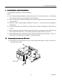
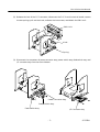
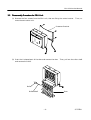
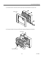
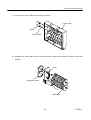
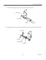
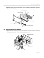
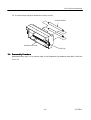
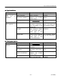
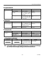
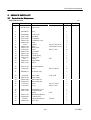
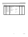
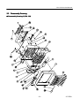
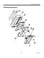
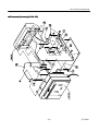
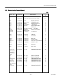
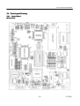
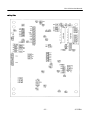
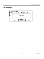
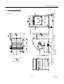
CITIZEN
Service Manual
Model: PPU-231
Line Thermal
Printer/Presenter Unit
Rev. 1.00 Newly issued on May 12, 1999
Jap
Japan CBM Corporation
Information Systems Div.
PPU-231 Service Manual
INTRODUCTION
This manual describes the disassembly, reassembly, and maintenance procedures of the line
thermal presenter/printer PPU-231. It is intended for field maintenance men.
FEATURES
Packed with features, this small line thermal printer/presenter has a wide range of uses: a terminal device for various data communication, an instrumentation terminal, an outdoor information
terminal or a device that prints various tickets and coupons.
Please read this manual thor-
oughly before you use the printer/presenter to ensure it is implemented correctly.
1. Small, lightweight, and installable in a narrow area
2. High speed and low noise, owing to line thermal print
3. Long-life printing head and high reliability, owing to the simple mechanism
4. Easy paper-loading, owing to the auto-loading function
5. Built-in input buffer.
6. Capable of printing a bar code (Special command)
7. You can choose where you attach the power connector, interface connector, etc.
8. Large diameter paper roll support
–2–
CITIZEN
PPU-231 Service Manual
CONTENTS
1.
HANDLING AND MAINTENANCE OF PRINTER ..........................................................................4
2.
SPECIFICATIONS ...............................................................................................................................5
2.1
3.
4.
5.
6.
7.
Basic Specifications ....................................................................................................................5
DISASSEMBLY AND REASSEMBLY ................................................................................................6
3.1
Disassembly Procedure for PPU Unit .......................................................................................6
3.2
Disassembly Procedure for PRU Unit .......................................................................................9
3.3
Disassembly Procedure for PMU Unit ....................................................................................13
3.4
Reassembly Procedure..............................................................................................................15
TROUBLESHOOTING ......................................................................................................................16
4.1
Troubleshooting Procedure.. ………………………………………………………………..………16
4.2
Troubleshooting Guide.. ..…………………………………………………………………….……..16
SERVICE PARTS LIST ......................................................................................................................19
5.1
Parts List for Mechanism.........................................................................................................19
5.2
Disassembly Drawing ...............................................................................................................21
5.3
Parts List for Control Board ...................................................................................................24
5.4
Parts Layout Drawing ..............................................................................................................26
DRAWING ...........................................................................................................................................29
6.1
Block Diagram..........................................................................................................................30
6.2
Circuit Diagram ........................................................................................................................31
OUTER DIMENSION ........................................................................................................................32
h: For the printer mechanism LT380V and auto cutter ACS-230F, refer to the separate Service
Manuals.
–3–
CITIZEN
PPU-231 Service Manual
1. HANDLING AND MAINTENANCE OF PRINTER
See the User’s Manual coming with the printer body.
–4–
CITIZEN
PPU-231 Service Manual
2. SPECI
ECIFICATIONS
2.1 Basic Specifications
Item
Printing system
Printing width
Dot density
Printing speed
Printing columns and
character size
Line interval
Character types
Bar code type
Paper
Presenter
Interface
Input buffer
Command
Sensors
Supply voltage
Power consumption
Weight
Outer dimensions
Operating temperature
and humidity
Storage temperature
and humidity
Reliability
Description
Line thermal dot printing
72 mm (576 dots/line)
8 dots/mm (Width, Length)
62.5 mm/sec. (At maximum speed), (500-dot line/sec.)
48 columns (12´24 Font A) 1.25´3.00 mm
64 columns (9´24 Font B) 0.88´3.00 mm
Initial value: 4.23 mm (1/6 inch)
Can be set with a command (1/203 inch at minimum)
Alphanumeric, Japanese, International characters
UPC-A, JAN(EAN) 13-/8-column, ITF, CODE 39, CODE 128, CODABAR
Thermal paper roll
Width:80 mm
Outer diameter:
f203 mm (Max.), (When using PHU)
Inter diameter:
f25.4 mm (Max.)
Thickness:
60~85 µm
Recommended paper TF-50KS-E, E2C (made by Nippon Seishi)
Length of normal issue
64~305 mm (Can be adapted to issue 457 mm lengths)
2.5~12 inches (Can be adapted to issue 18-inch lengths)
Serial (RS-232C), Parallel (Conforms to CENTRONICS)
4 KB
ESC/POS
Paper near end sensor (When using PHU, position adjustable)
Paper end sensor (When using PMU)
Black mark Sensor (Option)
24 V DC +/- 7%
100 W
PPU: 1.6 kg (Control PCB included)
PHU: 0.9 kg (Paper roll excluded)
PPU: 144.7(W)´160(D) ´172(H) mm
PHU: 132.2(W)´120(D) ´125.2(H) mm
*: Protruding parts are not included.
5~40°C, 35~85 % RH (No dew condensation)
-20~60°C, 10~90% RH (No dew condensation)
Printing head life:
Pulse resistance : 50 million pulses or more (Print rate 12.5%)
Wear resistance: 30 km or more (With recommended thermal paper
at normal temperature and humidity)
Auto cutter life:
300,000 cuts (With recommended thermal paper at normal temperature and humidity)
–5–
CITIZEN
PPU-231 Service Manual
3. DISASSE
SSEMBLY AND REASS
REASSE
SSEMBLY
For maintenance operations, note the following:
Notes:
(1) Do not disassemble/reassemble or adjust the machine, if it functions properly. Particularly,
do not loosen screws on any component, unless necessary.
(2) After completing an inspection and before turning on the power, be sure to check that there is
no abnormality.
(3) Never try to print without paper installed in the printer.
Check that the printing paper is
properly set.
(4) During maintenance, be careful not to leave parts or screws unattached or loose inside the
printer.
(5) When handling the thermal head and control board, do not use gloves or other aids which can
easily cause static electricity. Also, avoid a place where static electricity can occur.
(6) When disassembling or reassembling, check cables and boards for any damage.
Do not run
cables into a narrow space or set cables in improper positions.
3.1 Disasse
ssembly Procedure for PPU
PPU Un
Unit
(1) Disconnect the two connectors from the control board and detach the PRU unit after removing the four screws.
PRU Unit
–6–
CITIZEN
PPU-231 Service Manual
(2) Release the lock of the FCC connector, disconnect the FCC from the control board, remove
the two springs, pull out the knob, unfasten the two screws, and detach the PMU unit.
PMU Unit
Knob
Spring
(3) Disconnect the connectors of power connector assy, power switch assy, feed switch assy, and
I/F connector assy from the control board.
Power Connector Assy
Power Switch Assy
Feed Switch Assy
I/F Connector Assy
–7–
CITIZEN
PPU-231 Service Manual
(4) Disengage the four claws that are holding the control board and detach the control board.
Control Board
DIP Switch
(5) Remove the side frame L and R.
Side Frame L
Side Frame R
Center Frame
–8–
CITIZEN
PPU-231 Service Manual
3.2 Disasse
ssembly Procedure for PRU Un
Unit
(1) Remove the four screws from the PRU unit, that are fixing the cutter bracket.
Then, re-
move the auto cutter unit.
Presenter Bracket
(2) Push the U-shaped part of the door and remove the door.
Then, pull out the roller shaft
and remove the roller.
Roller
Door
Roller Shaft
–9–
CITIZEN
PPU-231 Service Manual
(3) Remove the four screws that are fixing the upper case and detach the upper case.
Upper Case
(4) Remove the feed roller assy and PE sensor assy by pulling them horizontally.
PE Sensor
Feed Roller Assy
– 10 –
CITIZEN
PPU-231 Service Manual
(5) Pull out the roller shafts and remove the rollers.
Lower Case
Roller
Roller Shaft
(6) Release the claws that are fixing the feed roller gears and remove the feed rollers and
bushes.
Bush
Feed Roller Gear
Feed Roller
– 11 –
CITIZEN
PPU-231 Service Manual
(7) Pull out the motor gear, remove the two screws, and detach the motor.
Side Plate
Motor Gear
Motor
(8) Disengage the E-ring, and remove the drive gear, clutch spring, and slip gear in that order.
Drive Gear
E-Ring
Clutch Spring
Slip Gear
– 12 –
CITIZEN
PPU-231 Service Manual
(9) Remove the auto cutter from the presenter bracket and detach the paper guide, mouse plate
F2, and mouse plate R2.
Mouse Plate F2
Mouse Plate R2
Auto Cutter
ACS-230F
Presenter Bracket
Paper Guide
3.3 Disasse
ssembly Procedure for PMU Un
Unit
(1) Remove the four screws that are fixing the mechanism cover and release the claw that is
fixing the connect board. Then, remove the mechanism cover.
Mechanism Cover
Connect PCB
Printer Mechanism
– 13 –
CITIZEN
PPU-231 Service Manual
(2) Disconnect the two connectors and one FPC from the connect board.
Connector (with Lock)
Connect Board
(3) Remove the two screws that are fixing the mechanism bracket and detach the printer
mechanism.
Mechanism Bracket
Printer Mechanism
– 14 –
CITIZEN
PPU-231 Service Manual
(4) Unhook the springs and remove the cushion rollers.
Cushion Roller
Mechanism Cover
Spring
3.4 Reassembly Procedure
Reassemble each part in the reverse order of the disassembly procedures described in Sections
3.1 to 3.3.
– 15 –
CITIZEN
PPU-231 Service Manual
4. TROUBLESHOOT
OOTING
4.1 Troubleshoot
ooting Procedure
When a trouble occurs, confirm its phenomenon, locate a defective part in accordance with 4.2
Troubleshooting Guide, and troubleshoot as described below.
l Phenomenon:
Find a trouble phenomenon in this column.
If there are multiple
phenomena, take all the corresponding items into consideration.
This allows you to specify a hidden defective part.
l Cause:
Lists as many possible causes as possible.
Guess a trouble cause out
of them and take its check method to specify the trouble cause.
l Check Method: Describes a check method to specify a trouble cause.
l Remedy:
Troubleshoot by taking a remedy described in this column.
By troubleshooting in accordance with the above-mentioned procedure, you can troubleshoot efficiently with fewer misjudgments.
4.2 Troubleshoot
ooting Guide
l Printing failure
Phenomenon
No printing
Faint printout
Cause
Faulty DC output voltage from the AC
adapter
Faulty printer mechanism
Faulty DC power supply
from the AC adapter
Missing dots
Foreign substance is
adhered to the thermal
head.
Badly blurred
printout
Faulty DC power supply
from the AC adapter
Dirt is attached to the
thermal head.
Bad printing qual- Faulty paper
ity
Check Method
Remedy
Check whether the 24V Replace
the
AC
DC is output from the adapter.
AC adapter.
Replace the printer
mechanism unit.
Check whether the AC Replace
the
AC
adapter has enough adapter.
power margin.
Check whether any for- Dip a cotton swab or
eign substances are soft cloth in ethyl alcoadhered to the thermal hol and wipe the foreign
head.
substances with them.
Check whether the AC Replace
the
AC
adapter has enough adapter.
power margin.
Check whether dirt is Dip a cotton swab or
adhered to the thermal soft cloth in ethyl alcohead.
hol and wipe away the
dirt.
Check whether the pa- Replace it with
per meets the specifica- specified paper.
tions.
– 16 –
the
CITIZEN
PPU-231 Service Manual
l Paper feed
eed failu
ilure
Phenomenon
Paper feed motor
does not work or
does
not
run
smoothly.
Cause
Faulty connection of the
motor connector
Faulty DC power supply
from the AC adapter
Check Method
Check connection of the
motor connector.
Check whether the AC
adapter has enough
power margin.
Remedy
Connect the connector
correctly.
Replace
the
AC
adapter.
Check whether or not
the paper is jamming or
torn and caught in the
paper path.
in Check whether any foreign substance caught
in the platen gear or
motor gear in the
printer mechanism.
Check for any breakage
of the platen gear or
motor gear in the
printer mechanism.
Eliminate unnecessary
paper in the paper path
and set paper properly.
Faulty printer mechanism
Paper is not fed or Paper feed failure
fed irregularly
Foreign substance
the gear
Broken gear
Replace the
mechanism
printer
Eliminate the foreign
substance.
If it is broken, replace
the printer mechanism.
l Faulty paper ejection
Phenomenon
Cause
Check Method
Paper
is
not Wear of the clutch
ejected.
Paper being used is too Check the thickness of
thick.
the paper.
Deformation of the pa- Check whether the paper guide
per guide is deformed or
not.
DC power to the drive Check whether the AC
motor is insufficient.
adapter has enough
power margin.
Faulty paper path
Check whether paper is
left in the paper path.
– 17 –
Remedy
Replace the clutch.
Change the paper.
Replace
guide.
the
paper
Replace the AC adapter.
Eliminate the remaining paper.
CITIZEN
PPU-231 Service Manual
l Inoperative feed
eed rolle
ller
Phenomenon
Cause
The roller does not Faulty connection of the
turn.
motor connector
Foreign substance in
the gear
Broken gear
Check Method
Check connection of the
motor connector.
Check whether any foreign substance caught
in the motor gear or
feed roller.
Check for any breakage
of the feed roller gear,
gear in the clutch part,
or motor gear.
Remedy
Connect the connector
correctly.
Eliminate the foreign
substance.
If broken, replace the
parts.
l Faulty sensor
Phenomenon
Cause
Does not detect Faulty paper sensor
presence of paper.
Check Method
Check whether any foreign substances are
adhered to the window
of the paper sensor.
Faulty connection of the Check connection of the
paper sensor
paper sensor.
Remedy
Eliminate the foreign
substance.
Connect the connector
correctly.
l Faulty auto cutte
tter
Phenomenon
Cause
The cutter does not Faulty connection of the
functionl.
motor connector
Paper feed failure
(Paper jam)
Faulty auto cutter
Check Method
Check connection of the
motor connector.
Check whether the paper is jamming or not.
Remedy
Connect the connector
correctly.
Eliminate jammed paper in the paper path.
Replace the auto cutter.
l If the problem is not still solved
Phenomenon
Cause
Check Method
Remedy
Replace the control If solved, replaced the
board and check wheth- control board.
er the problem is solved
or not.
Note: If the no-paper co
condition is not detected while
ile the printer is runni
unning out of the recording p aper, it will print without th
the paper, leading to a trouble of
of the head, and so on.
– 18 –
CITIZEN
PPU-231 Service Manual
5. SERVICE PARTS LIST
5.1 Parts List for Me
Mechanism
EXPLODED VIEW
1/2
Ref. No.
Parts No.
1
E66201-070
Upper Case
1
2
E62040570
Door
1
3
4
5
6
7
8
9
10
11
12
13
14
15
16
17
18
E62020400
E6601-380
E6612-090
E8019-160
E8025-100
O-25
E8017-100
E8019-170
76G57459
E8024-120
E8019-180
E8519-020
E8019-190
E2.5
E8024-130
E8031-130
Lower Case
Side Plate
Feed Roller
Feed Roller Gear
Bush
O-Ring
Motor
Motor Gear
Screw
Gear Shaft
Slip Gear
Clutch Spring
Drive Gear
E-Ring
Roller Shaft
Roller
1
1
2
2
2
2
1
1
10
1
1
1
1
1
3
3
19
20
E6233-150
23G22839
Presenter Bracket
Screw
21
E40000315
PE Sensor Assy
22
23
24
25
26
27
ACS230F
E8022-140
E8010-290
E8010-270
71G57473
23G57466
Auto Cutter
Paper Guide
Mouse Plate F2
Mouse Plate R2
Screw
Screw
30
31
32
33
34
35
36
E8023-090
E8031-140
Mechanism Cover
Cushion Roller
Spring
Mechanism Bracket
Connect PCB
Printer Mechanism
Flat Cable
E6233-160
E70010905
LT380V
E4900-640
Description
P25 4C Silicon 50°
FM-120RA1 (24V)
M2´3 S Tite
E2.5
M2.6´8 B Tite
Q'ty
Remarks
1
12
1
ACS-230F
M2.3´5 S Tite
M2´6 S Tite
– 19 –
2057
LT380V
1
1
1
1
4
2
1
2
2
1
1
1
2
CITIZEN
PPU-231 Service Manual
EXPLODED VIEW
Ref. No.
Parts No.
40
41
42
43
44
45
46
47
48
49
E8010-310
E8010-320
E8010-330
23G29538
E8025-110
E8500-090
E4035-870
E8029-050
23G22821
2/2
Description
Center Frame
Side Frame L
Side Frame R
Screw
Locking Card Spacer
Edge Holder
Insulating Sheet
Knob
Screw
Spring
– 20 –
M3´5 S Tite
KGLS-6RF
EHS-11U
M3´8 S Tite
6612
Q'ty
Remarks
1
1
1
8
4
2
1
2
4
2
CITIZEN
PPU-231 Service Manual
5.2 Disasse
ssembly Drawing
ssembly Drawing-1 (PRU-130)
130)
l Disasse
– 21 –
CITIZEN
PPU-231 Service Manual
l Disasse
ssembly Drawing-2 (PMU-231)
– 22 –
CITIZEN
PPU-231 Service Manual
l Disasse
ssembly Drawing-3 (PPU-231)
31)
– 23 –
CITIZEN
PPU-231 Service Manual
5.3 Parts List for Control Board
1/2
Ref. No
Parts No.
Description
PPU-231
F
E70010985
23212-31 Main Assy (USA/EUR)
(1)
E 104-580
E 104-530
E 107-380
E 210-070
E 210-130
E2020040
E4101-720
E 104-690
1
1
1
1
1
1
1
1
1
1
IC1
IC2
IC3
IC4
IC5
IC6
IC7
IC102
(IC102)
(IC102)
E48000920
CPU
HD6413002F16
Gate Array
CBM202LA-00
RAM
GM76C8128C-55
HCMOS-IC
74HC04AF
Reset IC
M51953BPF-600C
I/F
SP232can
DC/DC Converter SI-8401L
EPROM
M27C1001-45XF1
ROM Label
IC Socket
2-644018-3
TA1
TA2
E 390-310
E 202-830
Tr. Array
Tr. Array
LB1650
TA8428K
1
1
TR1,4
TR2
TR3-5,8
TR9
E 358-080
E 358-090
E 359-190
E 359-170
Transistor
Transistor
Transistor
Transistor
RN1302
2SJ267-FD13
2SC2712-GR (TE85R)
2SC4671-AN
2
1
5
1
D1-8
E 400-470
Diode
S1G-GI1
8
ZD1
E 406-090
Z. Diode
RD6.2FM
1
C1,2,5,7-9
16-20,101
149-152
CP1-6,101
102
C3
C4
C6,10,15,21
C11-14
C22,154
C102-110
112-118,148
153
C119-147
E2110-865
C. Cap.
GRM40CH470J50PT
24
E2230-260
E2230-250
E2110-880
E2110-875
E2110-900
E2110-905
Ele. Cap.
Ele. Cap.
C. Cap.
C. Cap.
C. Cap.
C. Cap.
SME35VB220M
SME16VB470M
GRM40B102K50PT
GRM40B103K50PT
GRM40B471K50PT
GRM40CH101J50PT
1
1
4
4
2
18
E2110-870
C. Cap.
GRM40F104Z50PT
29
– 24 –
CITIZEN
PPU-231 Service Manual
2 /2
Ref. No
Parts No.
R1,2,30,35
40,42,48,50
55
R3,24,29,34
39
R4-6,8-12,15
17,19,46,47
51-54
R7
R13,21,26,31
36
R14,49
R16,22,23,27
28,32,33,37
38
R20,41,43
R44,45
F1
F2
X1
L3,6-14
16-18,20-28
30-48
L4,5,15,19
L1,2
DS1,2
CN1
CN2
CN3
CN4
CN5
CN6
CN7,8
CN9
CN10
PCB
Description
Chip Resistor
CR18-332J
Chip Resistor
CR18-101J
Chip Resistor
CR18-103J
Chip Resistor
CR18-682J
Chip Resistor
CR18-181J
Chip Resistor
CR18-221J
Chip Resistor
CR18-333J
Chip Resistor
Chip Resistor
CR18-102J
CR18-331J
PPU-231
F
9
5
17
1
5
2
9
3
2
E4005-795
E4005-770
E 501-400
Fuse
Fuse
X'tal
MS3
MQ1.5
CSTCS16.00MX0C3-TC
1
1
1
E4009-490
Fe. Beads
BLM21A121S
41
E4009-480
E4009-280
E5103-510
Fe. Beads
Fe. Beads
DIP Switch
BLM41P600S
BL02RN2-R62
KSD-08
4
2
1
E4800-915
E48000925
E4800-945
E48000765
E48000930
E48000755
E48000940
E48000650
E48000935
Wafer Assy
5267-05A-X
Wafer Assy
5273-02A
Wafer Assy
5267-04A-X
Connector
53014-0510
Connector
53014-0610
Connector
53014-0310
Connector
5597-20CPB
Wafer Assy
5267-06A-X
Connector
53313-2015
PCB
212-31
Power Connector Assy
Power Switch Assy
Feed Switch Assy
I/F Connector Assy
Serial (mm)
I/F Connector Assy
Serial (inch)
I/F Connector Assy
Parallel
E40000320
E5109-230
E5109-220
E4900-580
E4900-590
E4900-600
– 25 –
1
1
1
1
1
1
2
1
1
1
1
1
1
1
1
1
CITIZEN
PPU-231 Service Manual
5.4 Parts Layout Drawing
5.4.1
Control Board
l Parts Side
– 26 –
CITIZEN
PPU-231 Service Manual
l Dip Side
– 27 –
CITIZEN
PPU-231 Service Manual
5.4.2
Connect Board
(Square hole)
– 28 –
CITIZEN
PPU-231 Service Manual
6. DRAWING
The following lists the reference drawings for maintenance, and so on.
• Block diagram
• Circuit diagram
– 29 –
CITIZEN
PPU-231 Service Manual
6.1 Block Diagram
– 30 –
CITIZEN
PPU-231 Service Manual
6.2 Circuit Diagram
– 31 –
CITIZEN
Power connector)
Unit: mm
(Paper ejection height)
(Paper insertion height)
(Paper roll width)
– 32 –
Feed switch mounting hole
(on both sides)
7. OUTER DIMENSION
I/F cable mounting hole
(on both sides)
ower switch mounting hole
on both sides)
(Paper center)
PPU-231 Service Manual
CITIZEN