1
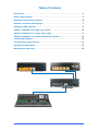
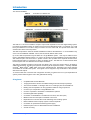
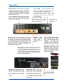
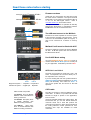
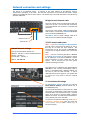
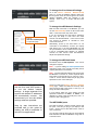
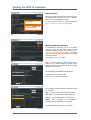
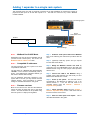
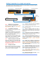
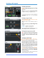
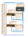
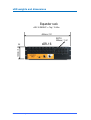
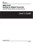
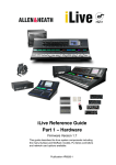
Available with AES digital outputs Available with AES-Out xDR-16 Input/Output Expander Getting Started Guide Publication AP8331 Safety Instructions Before starting, read the Important Safety Instructions printed on the sheet supplied with the equipment. For your own safety and that of the operator, technical crew and performers, follow all instructions and heed all warnings printed on the sheet and on the equipment panels. System operating firmware The feature set of the iLive system is determined by the firmware (operating software) that runs it. Firmware is updated regularly as new features are added and improvements made, and is available for download from the Allen & Heath web site. This guide relates to Version 1.9 firmware. Some of the details shown in this guide may differ from those in the current release of firmware. Refer to the web site for the latest version and read the Release Notes that come with each version of firmware for further details. Note: Make sure all your iLive MixRacks, Surfaces and xDR expanders are running the same version of firmware, and that the Editor software, MixPad and Tweak apps are compatible. xDR16 expanders loaded with V1.9 firmware are not compatible with V1.8 or earlier iLive hardware. This user guide This guide provides quick start information for the iLive xDR-16 input/output audio expander which is one component in the iLive Series. Further information To find out more about the iLive range refer to the iLive Fixed Format Systems Getting Started Guide AP7141 and the user guides associated with each system component. Use the HELP MANUAL available from the iLive Surface TouchScreen UTILITY menu and the Editor software. Refer to the Allen & Heath web site for the latest information on iLive and additional resources for download. IMPORTANT- Please read carefully By using this Allen & Heath product and the software within it, you agree to be bound by the terms of the relevant End User Licence Agreement (EULA), a copy of which can be found on the Allen & Heath website in the product's pages. You agree to be bound by the terms of the EULA by installing, copying, or otherwise using the software. The iLive range of products complies with the European Electromagnetic Compatibility directives 89/336/EEC & 92/31/EEC and the European Low Voltage Directives 73/23/EEC & 93/68/EEC. Any changes or modifications to the equipment not approved by Allen & Heath could void the compliance of the product and therefore the user’s authority to operate it. iLive xDR-16 Getting Started Guide AP8331 Issue 2 Copyright © 2012 Allen & Heath. All rights reserved ALLEN&HEATH Allen & Heath Limited, Kernick Industrial Estate, Penryn, Cornwall, TR10 9LU, UK http://www.allen-heath.com iLive xDR-16 Getting Started Guide 2 AP8331 iss.2 Table of Contents Introduction ............................................................................................................................................... 4 xDR-16 panel layouts ............................................................................................................................ 5 Read these notes before starting.................................................................................................... 6 Network connection and settings ................................................................................................... 7 Adding the xDR expander ................................................................................................................... 9 Adding 1 expander to a single rack system .............................................................................10 Adding 2 expanders to a single rack system ..........................................................................11 Adding an expander to a linked FOH/Monitor system ........................................................12 Patching xDR signals ..........................................................................................................................13 The xDR input/output routing..........................................................................................................14 Weights and dimensions...................................................................................................................15 Manufacturer’s Warranty ...................................................................................................................16 iLive xDR-16 Getting Started Guide 3 AP8331 iss.2 Introduction Two versions available: xDR-16 16 mic/line in, 8 XLR line out xDR-16-DO 16 mic/line in, 4 XLR line out + 2 dual channel AES out The xDR-16 is a 3U rack mountable 16 input 8 output audio expander for the iLive digital mixing system. It provides an affordable solution for adding more sources and distributing audio. For example, you could have your MixRack on one side of stage, one xDR-16 on the other side, and provide more audio and another Port B at the FOH mix position. The xDR-16 expander is similar to the iDR-16 MixRack but without the DSP built in. It can be added to any of the of six iLive MixRack available – iDR-16, iDR-32, iDR-48, iDR-64, iDR10, iDR0. Up to two xDR-16 expanders may be added to a single MixRack system. One may be added to DualRack or FOH/Monitor linked systems. To connect to the xDR-16 the iLive MixRack must be fitted with an ACE network option card in its Port B. System control is also possible at the expander location with a built-in network switch for connecting a laptop or wireless router. The xDR-16 is a network device within the iLive system and must therefore have a unique IP address. The xDR-16 expander provides its own Port B slot allowing any of the iLive option cards to be fitted for additional networking, recording and personal monitoring at the expander location. Currently available are ACETM, MADI, DanteTM, MMO (Adat, Aviom, iDR) and EtherSound. Expander Port B input channels are available to use within the system. iLive signals can be mapped in any combination to the expander XLR and Port B outputs. To ensure trouble free connection and configuration and that you get the best out of your expanded iLive system, please read through the rest of this guide before starting. At a glance Compatible with all iLive MixRacks 16 high performance remote controllable analogue XLR mic/line input preamps Two versions available - 8 analogue XLR out or 4 analogue plus two dual AES out Existing xDR-16 expanders can be upgraded for AES out using an option kit Connect up to 2 expanders to single MixRack iLive Connect 1 expander to Dual-Rack or FOH/Monitor split iLive Provides digital snake capability Connection to the MixRack is via ACE link over CAT5, max 120m (400’) MixRack must have ACE option card fitted to its Port B Expander has its own Port B for local networking and recording options Built-in Network switch for laptop system control at expander Connection for optional iPS10 backup power supply Distinctive panel colour to differentiate from iDR-16 MixRack 3U rack mounting iLive xDR-16 Getting Started Guide 4 AP8331 iss.2 The xDR-16 Mic/Line inputs High performance, recallable analogue preamps for balanced or unbalanced microphone and line level signals. Gain, Pad and 48V are digitally controlled within the preamp. Digital Trim and Polarity are available within the DSP channel. Line outputs Line level, balanced XLR outputs. Nominal level +4dBu with +22dBu maximum providing +18dB headroom. iLive signals can be patched to any output socket using the OUTPUTS screen. The outputs are relay protected to prevent power on or off thumps. Inputs are identified by Slot (card position) and Socket (number), for example A1 or B8. Any input can be patched to any DSP channel using the PREAMP screen. AES digital out option Shown fitted in the last card position. Each socket handles two signals, in this case 5-6 and 7-8. Network A built-in 2 port network switch for plugging in a laptop or wifi router / access point located near the expander. Can also be used to bridge third party non-iLive network data over ACE to the network ports on the master MixRack. All devices on the iLive network must have compatible IP addresses. A recessed switch lets you reset the xDR IP address to factory default of 192.168.1.20. SYSTEM LOCK indicates expander digital audio is sync locked to the MixRack. ACE™ Port A Connect a single CAT5 cable up to 120m (400’) (depending on cable type) to link audio and control between the xDR and the MixRack. You do not need a separate Network cable because control is bridged over ACE. The xDR plugs into one of the two Link ports on the ACE option card fitted to Port B in the master MixRack. Backup power supply input The xDR has a mains power supply built in. This socket lets you add the external iPS10 rack mount power supply as a redundant backup. iLive xDR-16 Getting Started Guide Mains power input Use the IEC mains power cord provided with the xDR. The cord can be held in place using the plastic clip. Press the switch to power the unit on or off. Read the Safety Sheet provided with the unit before using the xDR-16. 5 Rack Ears Fit into a 19” rack or flightcase. Port B audio network option slot. If required, fit one of the option cards available for system expansion, recording and distributed audio networking. Capable of up to 64 outputs and 48 inputs, 48kHz sampling rate. Port B gets its signals from the MixRack via the xDR Port A ACE link and therefore shares audio with the XLR inputs and outputs. Refer to the Routing Map later in this guide for details on which signals are available. Fan Do not obstruct the fan or the ventilation slots on the side of the unit. AP8331 iss.2 Read these notes before starting Analogue version: Firmware Firmware versions V1.8 + AES digital version: Firmware Check that your iLive system and xDR are running the same version of firmware. The system must be loaded with V1.8 or higher for the analogue xDR-16, or V1.9 for the AES digital version. Refer to www.allen-heath.com for the latest version. V1.9 + The system firmware can be updated via USB key plugged into the Surface or using Editor software. The MixRack must be connected to do this. The xDR must connect to the MixRack The xDR is an audio expander for the iLive system. It does not have any DSP or process audio. It must connect to the iLive MixRack (DSP mix engine). It may not be connected to a Surface or used by itself. MixRack Port B must be fitted with ACE The xDR-16 expander connects to the iLive MixRack via ACE. An M-ACE option card must be fitted to the MixRack Port B slot. Port B ACE Mode setting Go to the MIXRACK SETUP / Mixer Pref screen to check that Port B ACE Mode option is correctly set for your application. Redundancy should be OFF. ACE Link 1 and Link 2 The ACE card provides two ACE ports, Link 1 and Link 2. The expander can connect to either port, or two expanders one to each port. Link 1 If you are working with two iLive systems linked for digital mic splitting (linked FOH/Monitors) or DualRack (128 channels), then make sure Link 1 is used for the system link, and Link 2 for the xDR expander. Link 2 Single iLive system = Expander 1 Expander 2 Linked iLive system = Digital split Expander CAT5 cable Allen & Heath can provide: The xDR-16 connects to the iLive MixRack using a CAT5 cable. A cable is not provided with the xDR because its length is specific to the application, local or remote. Part AH7813 2m (6.6’) Neutrik Etherflex cable with EtherCon locking connectors. Use STP (shielded twisted pair) CAT5e cable. We recommend that you use the Neutrik EtherCon connector which has a shell that protects the connections and locks it in place when plugged into the mating EtherCon socket provided on iLive. Protective dust caps are available for these connectors. Part AH7000 80m (264’) drum of Neutrik Etherflex with EtherCon locking connectors. Part AH8721 120m (400’) drum of Neutrik Etherflex with EtherCon locking connectors. iLive xDR-16 Getting Started Guide 6 AP8331 iss.2 Network connection and settings The xDR-16 is a networked device. It connects to the same network as the MixRack, Surface, TouchScreen and laptop or wifi router. The xDR and each device on the network must have a unique address compatible with the rest of the system. The easiest way to work with the xDR is to use the factory default IP addresses. Bridge Control Network cable The iLive network must be bridged along with the audio over the Link 1 and Link 2 ACE connections so that the MixRack can control the connected xDR expanders. Use the short CAT5 jumper cable provided with the ACE card kit to connect from a MixRack NETWORK port to the ACE card BRIDGE port. NETWORK Short BRIDGE cable The xDR-16 does not need a Bridge cable as its ACE port has the network internally bridged. Network control 64x64 audio TCP/IP network addresses Note - If you are connecting two xDR expanders you will need to change the IP address of one so that they do not have the same address. We recommend you set the second to 192.168.1.21. Connect one, change its address, then connect the other. Default Network settings Factory reset IP address defaults are: MixRack 192.168.1.1 Sub mask 255.255.255.0 Surface 192.168.1.2 TouchScreen 192168.1.3 Note - If you are connecting the xDR to a MixRack in a linked iLive system you may need to change the IP addresses of the second MixRack, Surface and TouchScreen to avoid conflict with the first system. This is because the two iLive system networks are bridged via ACE. xDR-16 192.168.1.20 The xDR looks for a MixRack with default address 192.168.1.1 and connects automatically when it finds it. If the MixRack has a different address you will need to add the xDR manually. If the IP addresses have been changed or your system fails to connect you may need to reset the network settings. To reset Network Settings For the MixRack, Surface and xDR-16 locate the Reset Network Settings recessed switch next to the NETWORK ports. To reset the IP addresses turn the system off. While using a thin, pointed object to press and hold in the recessed switch, turn the device back on. Hold the switch in for at least 15 seconds while it reboots. Release the switch. This will reset the addresses to factory default as shown in the table. To reset the TouchScreen address go to its UTILTY / Network / Network Setup page and touch the Reset Network Settings button. Touch Apply to reboot the system. iLive xDR-16 Getting Started Guide 7 AP8331 iss.2 To change the iLive Network Settings Go to the UTILTY / Network / Network Setup page. To access the MixRack settings make sure the drop down menu at bottom right of the screen displays MASTER. Make the changes to the settings. Touch Apply to accept and reboot the system. To change the xDR Network Settings With the xDR connected to the MixRack you can use the Network Setup screen as above but select xDR 1 or xDR 2 from the drop down menu. If you are connecting two new xDR-16 expanders then they are likely to both have the same 192.168.1.20 default address. In this case connect one, change its address to 192.168.1.21, then connect the second. Type in 192.168.1.20/Setup.html to open this page Alternatively, power up the xDR while it is not connected to the MixRack, connect your laptop LAN (wired) port to the xDR NETWORK port and use your browser to find it. Make sure the LAN port is set for compatible static address, for example 192.168.1.10 with subnet mask 255.255.255.0. Adjust and Update the settings. To change the xDR Unit Name The default name is xDR Expander. This can be changed if required. Note - If you are adding two xDR expanders then change the name of one or both so that they can be uniquely identified on the network. Note - The xDR expander settings are stored in the iDR MixRack it connects to, not the expander itself. They relate to which ACE port you plug into, Link 1 or Link 2. For this reason make sure you plug each expander into the correct ACE port. Use the TouchScreen UTILTY / Network / Network Setup page. Select the xDR from the drop down menu at bottom right of the screen. Touch Apply to accept and reboot the system. Note - The easiest way to work with the iLive and xDR system is to use the default network settings. A single expander iLive system with default IP addresses will automatically connect. We recommend you use the default settings wherever possible. In most places within the iLive system the xDR expander is referred to as ‘xDR 1’ or ‘xDR 2’. This depends on which of the two ACE ports, Link 1 or Link 2 the xDR is plugged into. The NETWORK ports The xDR-16 features a built-in network switch with two ports. This lets you plug in your laptop or wifi router / access point at the xDR location if that is more convenient. Step by step instructions are provided later in this guide for adding the xDR-16 expander in various iLive applications. iLive xDR-16 Getting Started Guide You can also transport third party non-iLive network traffic between the xDR and MixRack using ACE as a network tunnel. 8 AP8331 iss.2 Adding the xDR-16 expander Auto detection When connected for the first time, the xDR-16 looks for a MixRack with the default 192.168.1.1 address. It will connect automatically if it finds it. An xDR-16 is connected to ACE Link 1 To check expander status go to the TouchScreen UTILTY / Network / Expander Setup page. Link 2 is available but no expander fitted Manually add the expanders If the MixRack IP address is not set to its default 192.168.1.1 then you will need to add the xDR expander manually using the TouchScreen UTILTY / Network / Expander Setup page. This needs only to be done the first time the xDR is connected to the iLive system. Touch the Add Expander button. Note - If you are adding two xDR expanders then make sure you have changed the name and IP address of one or both so that they can be uniquely identified on the network. The list displays the available xDR expanders. Highlight the one you want to add. Touch Apply to inspect the expander. The Inspection window displays information about the expander. Type Shows which ACE port it is connected to, Unit name Version The network name of the expander, The firmware version of the xDR-16, Master The IP address of the MixRack it currently points to (last MixRack connected). To add the expander touch the Apply button. iLive xDR-16 Getting Started Guide 9 AP8331 iss.2 Adding 1 expander to a single rack system This example shows one xDR-16 expander connected to an iDR-16 MixRack to increase the number of physical mic/line inputs to 32 and XLR outputs to 16. The xDR can connect to any of the 6 MixRack models available. xDR-16 Expander Port B Network or recording option ACE Port B ACE option card MixRack Surface ACE ACE Link 1 Network Bridge Note 1 - Step 1 Install the ACE option card into the MixRack Port B slot following the instructions provided with the card. MixRack Port B ACE Mode Redundant Link must be OFF for MixRack Port B (use the second or third option). This is set in the MIXRACK SETUP / Mixer Pref screen. Note 2 - Step 2 (Optional) Install any option card you require into the xDR-16 Port B slot. Compatible IP addresses Step 3 Bridge the MixRack network over ACE by connecting one of its NETWORK ports to the ACE card BRIDGE socket using the CAT5 jumper cable provided with the card. The xDR expander and iLive system must have compatible IP addresses. The xDR looks for a MixRack with default address 192.168.1.1 and connects automatically when it finds it. If the MixRack has a different address you will need to add the xDR manually. Step 4 Connect the xDR to the MixRack using a suitable CAT5 cable between the xDR ACE port and MixRack Port B ACE Link 1 socket. If the IP addresses have been changed or your system fails to connect you may need to reset the network settings. More information on network settings is described elsewhere in this guide. Note 3 - Step 6 Power up the system. The xDR will connect automatically if the MixRack IP address is set to its default 192.168.1.1. If not, the xDR will need to be manually added using the UTILITY / Network / Expander Setup screen. Firmware versions Must be the same for the xDR and the MixRack. Check the Allen & Heath web site for the latest version. The xDR firmware can be updated using the iLive system or a laptop running Editor. Step 7 Check expander status using the UTILITY / Network / Expander Setup screen. Also check that the firmware versions are the same. Step 8 Patch the xDR inputs and outputs. described elsewhere in this guide. iLive xDR-16 Getting Started Guide 10 AP8331 iss.2 This is Adding 2 expanders to a single rack system This example shows two xDR-16 expanders connected to an iDR-16 MixRack to increase the number of physical mic/line inputs to 48 and XLR outputs to 24. xDR-16 Expander 1 Port B network option xDR-16 Expander 2 Second Port B option ACE Port B ACE option card MixRack Surface ACE ACE Link 2 Network Bridge Note 1 - Step 1 Install the ACE option card into the MixRack Port B slot following the instructions provided. MixRack Port B ACE Mode Choose the third Mode (Redundancy Off – 1-32 Lnk1, 33-64 Lnk2) . This is set in the MIXRACK SETUP / Mixer Pref screen. Note 2 - Step 2 (Optional) Install any option cards you require into the xDR-16 Port B slots. Compatible IP addresses Step 3 Bridge the MixRack network over ACE by connecting one of its NETWORK ports to the ACE card BRIDGE socket using the CAT5 jumper cable provided with the card. The xDR expanders and iLive system must have compatible IP addresses. The xDR looks for a MixRack with default address 192.168.1.1 and connects automatically when it finds it. If the MixRack has a different address you will need to add the xDR manually. Step 4 Connect the first xDR to the MixRack by plugging a suitable CAT5 cable between the xDR ACE port and MixRack Port B ACE Link 1 socket. If the IP addresses have been changed or your system fails to connect you may need to reset the network settings. More information on network settings is described elsewhere in this guide. Note 3 - Step 5 Power up the system with the one xDR. The xDR will connect automatically if the MixRack IP address is set to its default 192.168.1.1. If not, add the xDR manually using the UTILITY / Network / Expander Setup screen. Different address for each xDR Step 6 Change the IP address of this xDR from 192.168.1.20 to 192.168.1.21 (and also change the Unit name if you add the xDR manually) using the UTILITY / Network / Network Settings screen so that it does not conflict with the address of the second xDR. Touch Apply to reboot the system. Unless the IP address of one has already been changed, both xDR expanders will have the same default address of 192.168.1.20. For this reason the address of one must be changed before the second is added to the system. Note 4 - ACE Link 1 Firmware versions Step 7 Add the second xDR by plugging a CAT5 cable from its ACE port to the MixRack Port B ACE Link 2 socket. The xDR will connect automatically or need to be added manually as described in Step 5 above. Must be the same for the xDR and the MixRack. Check the Allen & Heath web site for the latest version. The xDR firmware can be updated using the iLive system or a laptop running Editor. Step 7 Check expander status using the UTILITY / Network / Expander Setup screen. Also check that the firmware versions are the same. Step 8 Patch the xDR inputs and outputs. described elsewhere in this guide. iLive xDR-16 Getting Started Guide 11 AP8331 iss.2 This is Adding an expander to a linked FOH/Monitor system You can add one xDR-16 expander to a linked iLive system using digital mic splitter. This example shows an iDR-32 expanded with an xDR-16 for stage monitors, and an iDR-16 for FOH getting the 48 channels via an ACE digital mic split. Monitor Surface ACE Monitor MixRack Port B ACE option card xDR-16 Expander Network Bridge FOH MixRack Second Port B option ACE Link 2 = Expander ACE Link 1 = digital mic split FOH Surface ACE Note 1 - Step 1 Set up dual system with ACE mic split Port B of the master and slave MixRacks must have the ACE card options fitted. Use ACE Link 1 for the digital split. MixRack Port B ACE Mode Choose the third Mode (Redundancy Off – 1-32 Lnk1, 33-64 Lnk2) . This is set in the MIXRACK SETUP / Mixer Pref screen. Note 2 - Step 2 (Optional) Install any option card you require into the xDR-16 Port B slot. Compatible IP addresses Step 3 Bridge the master MixRack network over ACE by connecting one of its NETWORK ports to the ACE card BRIDGE socket using the CAT5 jumper cable provided with the card. The xDR expanders and iLive system must have compatible IP addresses. The xDR looks for a MixRack with default address 192.168.1.1 and connects automatically when it finds it. If the MixRack has a different address you will need to add the xDR manually. Step 4 Connect the xDR to the master MixRack by plugging a suitable CAT5 cable between the xDR ACE port and MixRack Port B ACE Link 2 socket. If the IP addresses have been changed or your system fails to connect you may need to reset the network settings. More information on network settings is described elsewhere in this guide. Note 3 - Step 5 Power up the system. The xDR will connect automatically if the MixRack IP address is set to its default 192.168.1.1. If not, add the xDR manually using the UTILITY / Network / Expander Setup screen. Firmware versions Step 6 Check expander status using the UTILITY / Network / Expander Setup screen. Also check that the firmware versions are the same for all racks. Must be the same for the xDR and the MixRack. Check the Allen & Heath web site for the latest version. The xDR firmware can be updated using the Surface or a laptop running Editor. Step 7 Patch the xDR inputs and outputs. described elsewhere in this guide. iLive xDR-16 Getting Started Guide 12 AP8331 iss.2 This is Patching xDR signals Patching single inputs For each channel press the strip SEL key, open the PREAMP screen and access the Source drop down menu. Select xDR 1 or xDR 2 as the source and then scroll the Slot and Socket to find the one you want to assign. Touch Apply to assign the source. To assign the source from an option card fitted to the xDR Port B select xDR 1 Port B from the drop down menu. Patching a range of inputs Go to the MIXRACK SETUP / Mixer Pref / Quick Input Source Select screen. Select the range of input channels you wish to assign. Select Remote (Port B) and the Start and End range from the xDR you wish to assign. For example: X1-A5 = Expander 1 Slot A Socket 5 X1-12 = Expander 1 Port B input 12 Each expander provides 16 XLR mic preamps and allows assignment from its Port B channels. xDR signals transported over ACE Note - All inputs and outputs associated with both xDR expanders and their Port B options are transported to/from the MixRack via the ACE connection. They share the 64 channels in each direction. Patching the xDR outputs Go to the MIXRACK SETUP / Mixer Pref / Expanders screen to select which range of 8 of the 64 ACE sends are to feed the XLR sockets. This choice depends on how you want to use the xDR Port B option if you have a card fitted. For example, the MMO (Mini Multi Out) card has a fixed map for its ADAT, iDR (HearBus) and Aviom outputs. You may want the XLR outputs mapped from other ACE channels to avoid clashing with the xDR Port B outputs you want to use. To patch signals to the xDR go to the OUTPUTS / Port B ACE screen. Scroll the Channel number until the xDR XLR or Port B channel is highlighted. Assign from the Select Output Source drop down menu in the usual way. The AES digital outputs, if fitted, are shown as XLR sockets and patched in the usual way. iLive xDR-16 Getting Started Guide 13 AP8331 iss.2 The xDR input/output routing MixRack Port B (ACE) Outputs: Map signals to Port B ACE using the OUTPUTS screen. Port B map 1-64. For the MMO card: ACE1 = ADAT1 ACE2 = ADAT2 ACE3 = ADAT3 ACE4 = ADAT4 ACE5 = ADAT5 ACE6 = ADAT6 ACE7 = ADAT7 ACE8 = ADAT8 ACE9 = ADAT9 ACE10 = ADAT10 ACE11 = ADAT11 ACE12 = ADAT12 ACE13 = ADAT13 ACE14 = ADAT14 ACE15 = ADAT15 ACE16 = ADAT16 ACE17 = ADAT17 ACE18 = ADAT18 ACE19 = ADAT19 ACE20 = ADAT20 ACE21 = ADAT21 ACE22 = ADAT22 ACE23 = ADAT23 ACE24 = ADAT24 Master MixRack XLR mic preamps identified: X1-A1 to X1-B8 Port B inputs identified X1-1 to X1-16 xDR 1 Choose which block of 8 ACE channels feeds the xDR 1 XLR outputs using the MIXRACK SETUP / Mixer Pref / Expanders screen. ACE 1-64 = Map to XLR out G1-8 in block of 8 ACE25 = iDR A1 ACE26 = iDR A2 ACE27 = iDR A3 ACE28 = iDR A4 ACE29 = iDR A5 ACE30 = iDR A6 ACE31 = iDR A7 ACE32 = iDR A8 ACE33 = iDR B1 ACE34 = iDR B2 ACE35 = iDR B3 ACE36 = iDR B4 ACE37 = iDR B5 ACE38 = iDR B6 ACE39 = iDR B7 ACE40 = iDR B8 ACE 1-64 = xDR Port B out 1-64 ACE 1-16 = From Mic Preamp A1 – B8 ACE 17-64 = xDR Port B in 1-48 (One xDR expander – Mode 2) ACE 17-32 = xDR Port B in 1-16 (Two xDR expanders – Mode 3) XLR mic preamps identified: X2-A1 to X2-B8 xDR 2 Port B inputs identified X2-1 to X2-16 ACE41 = Aviom1 ACE42 = Aviom2 ACE43 = Aviom3 ACE44 = Aviom4 ACE45 = Aviom5 ACE46 = Aviom6 ACE47 = Aviom7 ACE48 = Aviom8 ACE49 = Aviom9 ACE50 = Aviom10 ACE51 = Aviom11 ACE52 = Aviom12 ACE53 = Aviom13 ACE54 = Aviom14 ACE55 = Aviom15 ACE56 = Aviom16 iLive xDR-16 Getting Started Guide Choose which block of 8 ACE channels feeds the xDR 2 XLR outputs using the MIXRACK SETUP / Mixer Pref / Expanders screen. ACE 1-64 = Map to XLR out G1-8 in block of 8 ACE 1-64 = xDR Port B out 1-64 ACE 33-48 = Mic Preamp A1 – B8 ACE 49-64 = xDR Port B in 1-16 (Two xDR expanders Mode 3) 14 AP8331 iss.2 xDR weights and dimensions Expander rack xDR-16 WEIGHT = 7kg / 15.4lbs 482mm / 19" DEPTH 300mm / 11.8" xDR-16 132mm / 5.2" 3U iLive xDR-16 Getting Started Guide 15 AP8331 iss.2 Limited One Year Manufacturer’s Warranty This product is warranted to be free from defects in materials or workmanship for period of one year from the date of purchase by the original owner. To ensure a high level of performance and reliability for which this equipment has been designed and manufactured, read this User Guide before operating. In the event of a failure, notify and return the defective unit to the place of purchase. If this is not possible then please contact the authorised ALLEN & HEATH distributor or agent in your country as soon as possible for repair under warranty subject to the following conditions. Conditions Of Warranty The equipment has been installed and operated in accordance with the instructions in this User Guide. The equipment has not been subject to misuse either intended or accidental, neglect, or alteration other than as described in the User Guide or Service Manual, or approved by ALLEN & HEATH. Any necessary adjustment, alteration or repair has been carried out by an authorised ALLEN & HEATH distributor or agent. This warranty does not cover fader wear and tear. The defective unit is to be returned carriage prepaid to the place of purchase, an authorised ALLEN & HEATH distributor or agent with proof of purchase. Please discuss this with the distributor or the agent before shipping. If the unit is to be repaired in a different country to that of its purchase the repair may take longer than normal, whilst the warranty is confirmed and parts are sourced. Units returned should be packed to avoid transit damage. In certain territories the terms may vary. Check with your ALLEN & HEATH distributor or agent for any additional warranty which may apply. If further assistance is required please contact Allen & Heath Ltd. iLive xDR-16 Getting Started Guide 16 AP8331 iss.2