1
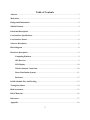
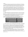
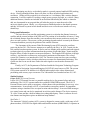
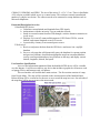
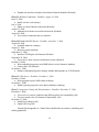
GPS Tracking System Amany El Gouhary – [email protected] Richard Wells – [email protected] Anthony Thatcher – [email protected] April 28, 2006 Table of Contents Abstract...........................................................................................................................................3 Motivation.......................................................................................................................................3 Background Information.............................................................................................................. 4 Similar Products.............................................................................................................................4 Functional Description.................................................................................................................. 5 User Interface Specifications........................................................................................................ 5 User Interface Extras.....................................................................................................................6 Software Description..................................................................................................................... 6 Block Diagram................................................................................................................................8 Hardware Description................................................................................................................... 8 Computing Platform........................................................................................................... 8 GPS Receiver....................................................................................................................... 9 LCD Display.......................................................................................................................10 Wireless Internet Connection...........................................................................................10 Power Distribution System............................................................................................... 11 Enclosure............................................................................................................................13 Initial Schedule Flow and Tasking............................................................................................. 13 Testing Procedures.......................................................................................................................14 Risk Assessment........................................................................................................................... 15 Bill of Materials............................................................................................................................16 References.....................................................................................................................................17 Appendix.......................................................................................................................................19 2 Abstract The purpose of this project is to design and construct a hand-held wireless GPS tracking device that can be tracked from the Internet. The project consists of three parts. The first part is a mobile device with an embedded GPS and wireless Internet connection to transmit its current location. The second part is a web server that will receive the data, parse it, and store it for access over the Internet. The third component is the user interface that will allow others to visually see where the hand-held GPS device is and has been. To view its location, one could use any device that can connect to the Internet such as a desktop computer, laptop, PDA, or cell phone. The data available through a browser includes a scalable map of the surrounding area, latitude, longitude, speed, and altitude of the hand-held device. The system is intended to be a general purpose tracking device; however, the user interface will be tailored to the university shuttle system. Motivation The intended application for our wireless GPS tracking device is the University of Utah shuttle system. As our group was formulating ideas for our project, we came to the conclusion that each of us was frustrated with the university shuttle system. We had several complaints in common: the shuttles didn’t come often enough; they were often late leaving us out in rain, snow, and heat; and worst of all, sometimes they never showed up at all. In an informal study of the punctuality of the university shuttle system by group members, it was found that on average the shuttle was three and one-half minutes late. The distribution of the shuttle departure times is presented in the following table. Time Frame of shuttle departure (in minutes) Early by 1-5 On time - 4 late Late by 5 - 10 Late by > 10 Never came Percent of departures 15% 38% 16% 23% 8% Table 1: University shuttle punctuality Each of us has many “horror” stories from our shuttle riding experience. We have seen a shuttle arrive 50 minutes late when it was scheduled to come every 10 minutes. It was snowing, but every shuttle that came would provide us with the update that it would “be there shortly.” We have experienced drivers running ten minutes late and going into the Union building or hospital for five minutes to get a drink. We have encountered shuttles that don’t come at all. Shuttle drivers are aware that they miss stops in the morning, but the problem continues. Being students with tight time schedules, the shuttle system’s unreliability can greatly affect us. We have been late to class and almost lost points on homework assignments due during class because the shuttle has made us late to class. We and many other university students have thought, “I wish I knew when the shuttle was coming.” Our device is engineered to address that question. It will allow anyone with an Internet connection to track the shuttle and know if it is early, on time, late, or even if it is skipping their stop. With this information students can adapt their schedule to meet the projected shuttle arrival times. 3 In designing our device we decided to make it a general purpose hand-held GPS tracking device. Having a hand-held form factor will allow it to have increased applications and usefulness. All that will be required for it to function is a 9-volt battery and a wireless Internet connection. It will be capable of tracking a single person, groups of people, or a vehicle. Many additional features, features not included in our baseline functionality but which we intend to add, are documented in our proposal that will tailor the project to meet the needs of the university shuttle system. Ideally, we will present our finished product to the shuttle operators and they will install a system in each shuttle and devices to access the user interface at every shuttle stop. Background Information The basic idea of any satellite positioning system is to calculate the distance between a satellite and the current location of the GPS unit. The position of each satellites is known. Using the calculated distance from four satellites, one can narrow their current position to exactly one place on earth’s surface. The accuracy of the positioning depends on how accurately the distance is measured and how precisely the position of the satellite is known. The forerunner of the current Global Positioning System (GPS) started as a military project in the late 50’s. The first two attempts were made by the Navy. In 1959, Transit was the first satellite-based navigation system. It used seven low altitude polar satellites and radio signals to obtain relatively accurate information about the position of individual ships. Transit used the Doppler Effect of radio frequencies to measure distances. The Doppler Effect did not yield high accuracy, was limited to certain areas, and required continuous measurements. The second system, the Timation, was introduced in 1964. The Timation system used two space satellites equipped with atomic clocks, which provided more accurate two dimensional positioning. This system was the first to use the time it takes the radio signals to reach earth to measure the distance. Finally, in 1973, the Department of Defense funded the Navigation Technology Program that resulted in Navigation System and Ranging (NAVSTAR), now known as GPS. The current GPS system consists of 24 satellites in 6 different orbits and provides a three dimensional positioning with accuracy up to ten meters. The 24th satellite was launched on June 26, 1993. Similar Products Laipac S-911™ Personal Locator Laipac S-911™ Personal Locator is a portable tracking device for personal safety and asset monitoring. The S-911™ operates under the worldwide GSM/GPRS network. The S-911™ Personal Locator can be used as emergency cellular phone with speed dialing for two-way voice communication. It can silently call 911, or an alternative emergency number, for immediate assistance using a simulated voice to report location and time stamp. It can send SMS messages to a control center and can also be monitored in real time on the Internet. The device measures 70 x 40 x 20 mm and has a built in lithium-ion rechargeable battery. There is software for realtime Internet tracking that requires an additional map database3. StarFinder I The Automatic Vehicle Location (AVL) system is designed to connect with a wide range of cell phone modems, VHF/UFH for digital radios and Satellite modems (ORBCOMM). It operates on 4 CDMA/1X, GSM/SMS, and GPRS. The size of the unit is 15 x 15 x 3.5 cm. There is StarFinder AVL software available which serves as a control center. This software can track an unlimited number of vehicles in real-time. The software needs to be connected to a map database such as Microsoft MapPoint.4 Functional Description Overview 1.Hand-held GPS device: a. Calculates current latitude and longitude from GPS signals b. Authenticates with the university’s secure.utah.edu network c. Sends its current location from the GPS through a wireless Internet connection to a web server. d. Displays if it is on/off, connected/disconnected, GPS fix/no GPS fix, current latitude, and current longitude on an LCD screen e. Is powered by a battery or an external power source 2.Web server: a. Receives and parses the data from the GPS device and stores it in a mySQL database b. Serves a web page that will dynamically query the database for current position and previous positions, download an appropriate map from an online database, overlay current position and previous positions on the map, and display current latitude, longitude, altitude, and speed. User Interface Specifications Access to the information transmitted from the hand-held GPS device will be viewable over the Internet. It will be accessible to any device that includes a graphical web browser such as laptops, PDAs, and Internet-ready cell phones. The user interface will include three main sections. The first section consists of a map from Google Maps. The map will be centered on the current position of the hand-held unit. Below the map will be a zoom bar for the user to use to zoom the map in or out. On each side of the map there will be arrows to move the map around. Illustration 1: Preliminary user interface 5 The second section will display the fields from the parsed NMEA data. It will include the following information: latitude, longitude, altitude, speed, GPS fix, and wireless Internet connection status of the hand-held device. These fields will be refreshed periodically with the data that is streaming from the hand-held GPS device. The third section will consist of buttons and drop down menus to customize the user interface. Through one drop down menu the map refresh interval will be selectable. Changing the map refresh interval will allow users with a slower Internet connection to be able to view the map, without it in a constantly in a refreshing state. User Interface Extras In order to make the user interface better suited for the university shuttle system, the user will have the option to associate the hand-held GPS unit with a shuttle route. The user interface will have a drop down menu to select which bus route they are interested in. Once a route is loaded, it will take the current location of the hand-held device and calculate the estimated time of arrival to your location. Your location can be selected from a box containing the stops along the selected route. In addition to the standard interface, a small version of the user interface will be added to better handle devices with a smaller screen. This will optimized for browsing on PDAs and Internet capable cell phones. Furthermore, a text messaging option for cell phones will be added. The user will be able to send a text message to the server and receive the estimated arrival time for a previously selected shuttle and stop. These selections will be saved and associated with the user account and mobile phone number. Software Description User Interface Web Page Software The user interface web page will use a combination of PHP and JavaScript to read information from the database, present it to the user by interfacing with Google Maps, and overlay the map with the position of the hand-held device. Google Maps has specified the interface to it through an API. We will use JavaScript to access the functions of the API. PHP will be used to obtain and process the data from the database. The web pages will be served and requested through a browser using the standard http protocol. Google Maps API: The map displayed by the user interface will be supplied by Google Maps. Google Maps has an API that allows anyone with a registered key to access maps from their database. The API can be accessed using JavaScript. The API provides the following functions which we will utilize in the design of the user interface. Zoom – We will provide a bar below our map that the user can interact with to choose the desired zoom level. Pan – Arrows will be supplied on each side of the map to allow the user to pan in any of the cardinal directions. Map display type – Three map displays are available from Google Maps. They are street view, satellite view, and hybrid view. Presently we are using hybrid view to combine streets and satellite data onto a single map. 6 Info boxes – These boxes pop up allowing us to provide information to the user. Presently the information presented includes the distance from the shuttle and links to get directions to or from the location clicked on. As an extra feature, we are planning to supplement the current information with shuttle specific data such as times the shuttle is scheduled to stop at the nearest shuttle stop. We interface with Google Local to provide directions. Drawing lines – This feature will be utilized to overlay the map with the path the shuttle has taken. Custom icons – To customize the interface for the shuttle system we have created shuttle icons that will mark the current location of the shuttle. Center – This functionality allows us to center the map on a specific latitude and longitude. The last longitude and latitude received from the hand-held device will be the default location to center the map on. Hand-held GPS Software: The data will be transmitted over the hand-held GPS device’s wireless Internet connection as raw NMEA data. We will run a stripped down version of Linux. Using the hostap program, we will be able to connect with the University’s secure.utah.edu wireless network, which requires 802.1x authentication. We will write a program that transmits the NMEA data over the Internet. Another function of this program will be to parse the latitude and longitude for display local on the unit's LCD. The program will be written in C. Web Server NMEA Parsing Software Software is required to process the data from the hand-held device. Since most of the budget for the project will be allocated toward the hardware, this project will utilize available open source applications to set up the server. Apache and MySQL are two programs which have a terrific track record for stability and reliability, which are required attributes of software used for the project. The server will receive the data from the hand-held unit in NMEA format. A Java program will take this data, parse it, and insert it into the database. 7 Block Diagram Hardware Description Some aspects of the GPS tracking system would be difficult to implement with a traditional microcontroller. Wireless authentication with the secure.utah.edu network is one of those aspects. To allow us to concentrate more on hardware and not programming a wireless 802.1x authentication program we chose to use a platform with a basic operating system. We will load onto the platform a program to handle the 802.1x authentication. The operating system of choice is a stripped down version of Linux. Hostap will handle the 802.1x authentication. Computing Platform We have decided to use the Gumstix platform as the computing platform for this project. The Gumstix platform was chosen for many reasons. One reason was that it had a processor, flash memory, and RAM integrated into a single board. Another benefit was that it was powerful enough to run an operating system that could support a 802.1x authentication program which reduces the complexity of obtaining a wireless Internet connection. Size was another factor that led to our choice of the Gumstix. 8 Processor: The Gumstix Connex 400-xm has an Intel XScale PXA 255 Processor on it. It runs at 400 MHz which is sufficiently fast. The XScale processor also supports the peripheral devices that we will connect to it. RAM: The Gumstix board has 64Mb of RAM. With running such a small stripped down version on Linux, it should be more than sufficient for our needs. Flash: The Gumstix 400-xm has 16Mb of onboard flash memory. The Gumstix runs a stripped down Linux implementation with a footprint of less than 4Mb. It runs a busybox version of common commands to help it save space. The rest will be available for our use. The things we will need the memory for include: the wireless networking driver, hostap (to authenticate with secure.utah.edu), and our program to receive the GPS data and send it over the Internet. 16 Mb of flash memory should be more than we need. Breakout Board: This board will allow us to connect peripheral devices to the processor. It has 56 through holes on 50mil pitch that breakout various GPIO lines and a jumper for enabling USB powered supply. Four of these holes are dedicated to the FFUART. Interface specifications: The breakout board will be powered by the five volt supply from our power distribution system. The breakout board will connect to the Gumstix through a 60 pin hirose connector. Four pins are dedicated to the FFUART which we will use to connect the GPS. We will use 8 GPIO lines to interface with the LCD. We will use another GPIO line to connect an LED to signal to the end user the unit has acquired a GPS fix. GPS Receiver The PG-11 GPS engine board manufactured by Laipac, provides the functionality we require, and is therefore the GPS receiver we have chosen to use. The board requires a 5 volt power source, which is consistent with the other components we have chosen. The board outputs NMEA data in the decimal latitude and longitude format we require for interfacing with Google Maps. The power consumption of the board is also within tolerance levels, as the board operates on 60 mA in standard mode, and while in trickle mode the board operates on only 25 mA. Interface: The GPS will connect to the FFUART holes on the breakout board. The engine board will output data conforming to the NMEA v2.2 protocol at RS232 levels. Because the FFUART uses TTL logic levels a MAX 232 chip will be needed to convert the GPS logic levels to the appropriate TTL logic levels that the Gumstix is expecting. The GPS will transmit the NMEA 9 formatted data over the connection to the Gumstix at 4800 baud. LCD Display We will use a character LCD screen to provide information to the user of the hand-held GPS device. We will display the current latitude, longitude, state of GPS fix, and status of the wireless Internet connection. We will use the AMC1602A-B-B6WTDW. It has two lines, each with a width of 16 characters. Size is an important factor. That is why we are limiting it to such a small LCD display. The LCD display is 80.0 x 36.0 x 14.0mm. It will be approximately the same length as the Gumstix, but a little wider. Because we have the Compact Flash wireless card, that will be the limiting factor in reducing the width. Interface: The LCD display has a built-in HD44780 controller. The input to the controller is an eight bit code from which it generates the character to display. We will use the PXA 255 GPIO pins to interface with the LCD. Also, this display can be powered by 5 volts which will allow us to use the same voltage that the Gumstix requires. LCD Extra: As a supplementary feature, a graphical LCD will be implemented on the hand-held GPS unit. It will use the existing wireless Internet connection to display the user interface. It would allow the unit to serve as a navigation system. Wireless Internet Connection CFStix CFStix is a Gumstix expansion board that connects via a 92-pin bus header to the Gumstix. It provides a type II Compact Flash socket. The Compact Flash socket will be used to connect a Compact Flash wireless Internet card. The Gumstix is reported to be compatible with any wireless card that has a Linux driver. Wireless Network Card: The card will be our communication portal to get the NMEA data streaming over the Internet. A wireless network card with 802.11b compatibility will be sufficient for our needs. The rate at which the GPS produces NMEA data relatively slow compared to the capabilities of the 802.11b standard. Currently three alternatives are available. 1. Socket Communication WL6000-320 2. Belkin F5D6060 3. Netgear MA701 Table 2 shows a comparison between the three cards. Because our device can be powered by a battery, power will be a concern. Therefore, the card manufactured by Socket will be our first choice. In case it does not work, we should be will use the card by 10 Netgear. The concerns with the Socket card include that it has not been tested before Gumstix and also has a reduced range. The Netgear card has been tested to work with the Gumstix. Gumstix users have also reported success using the card manufactured by Belkin. Socket Communications WL6000-320 Belkin F5D6060 Netgear MA701 802.11b compatibility yes yes yes CF Type I (II compatible) II I (II compatible) Range(open) 300 feet 490 feet 1000 feet Power consumption 170-280 mA in transmit 300 mA in transmit 350 mA in transmit Power save mode 250 mA in receive available 80 mA in power save mode 20 mA in idle Connected/Off LED yes yes yes Transmitting LED yes no yes Size 55.4*42.8*3.3 mm 42*70*7 mm 42.8*62*3.3 mm Weight 13.6 g 30 g 20 g Price $30-$40 $60 $40 Table 2: Comparison between three available wireless cards. Interface Specifications: Once the wireless adapter is connected and the driver is installed, the device will be addressed as an I/O device. All these devices have Linux drivers that have been tested on ARM processors. The CFStix has a power jack and can additionally be powered through the Gumstix. Power Distribution System A critical element of every mobile device is how it will be powered. The characteristics that we had in mind as we designed the power distribution system were cost, availability of the battery, capability of the battery to be recharged, dual power inputs (battery and external source), and obtaining the needed voltage level of 5 volts. The battery that we decided met these characteristics the best was a simple household 9V rechargeable battery. They are widely available, relatively cheap, and easy for a user of the hand-held device to understand how to replace. We found 9V batteries that were constructed of NiMH would give us a little more power, better battery life, and less memory. The 9V batteries can be recharged with any universal battery charger that supports 9V batteries. We will also include a connection on the external of the device where a user can connect an external power source. The requirements for the external power source include ability to output between six and eleven volts while providing sufficient current. This would allow universal AC/DC converters to be plugged into any standard outlet to power the device. During normal operation the external power source input would most likely be connected to an adapter 11 plugged into a car or shuttle cigarette lighter. This allows it to be mobile while the user doesn’t have to be concerned about battery life. To scale down the voltage to five volts we will use a voltage regulator. We found the Maxim 649 chip would meet our needs. It will take any voltage from six to eleven volts and output five volts. The Max 649 chip was chosen over the earlier considered Max 639 chip because it was able to handle more current. The hand-held unit has been calculated to consume about ½ amp of current. The Max 639 can only handle 225 mA. The Max 649 is approximately the same design with an external MOSFET that can handle the higher current. The Max 649 will help keep a steady voltage during the various stages of discharge of the battery. This will be important because the LCD display requires at least 4.75 volts for operation. Every battery powered mobile device also needs to have an on/off switch to prevent unneeded battery discharge. We will implement this switch. We have found a lighted SPST rocker switch that we will use. To have it lighted when it is on will help us for testing and the end user to know the system is being powered. Dual Power Inputs With any mobile device, power consumption is an important feature. Consumers demand portability and extra-long battery life, along with the ability to power the device from an outlet or a power source in their automobile. The hand-held GPS tracking device will meet these characteristics. The hand-held device will accept either of two power sources, external power or battery power. External power needs to be used when it is available and battery power needs to be consumed otherwise. Our dual power input circuitry is designed to meet this functionality. We will construct a microprocessor supervisory circuit to monitor both power supplies. Using the MAX6326 IC, a low-power reset IC, we will choose external power if it is available and battery power if it is not. When the voltage from the external power source is not available, the MAX6326 will assert a voltage on the gate of a transistor allowing the battery current to flow through and power the device. When external power is not available, the MAX 6326 will not apply the voltage to the transistor and external power will power the system. The MAX6326 has the additional feature that it will cleanly switch between the two power supplies. The MAX6326 will not switch the power supply source until the contact bouncing has concluded. Low Battery Detection Another important element to a mobile power system is you have to know when your battery is about to die. We will implement a low battery indicator so the user will know when they need to recharge their battery or switch to an external power source. The circuit will be composed of a MC34064 undervoltage sensing circuit and a not gate. This stage of the power supply will come after the DC-DC down conversion. The input will be a 5V signal. When the 12 MC34064 senses an input voltage lower than 4.6 V it will lower the reset signal. The not gate will invert that to an asserted high signal and source the current required to power the LED to inform the user that their battery is about to die. The built-in hysteresis of the MC34064 will prevent the user from seeing the low battery light intermittently turning on and off when the output is around 4.6V. Once the low battery LED is illuminated, it should stay on until the battery dies or an external power source is applied. Size One of the main design considerations of this project has been size. The Gumstix measures 80mm x 20mm x 6.4 mm. The other two expansion boards are roughly the same size. With the three connected it should be less than 30mm high. The compact flash wireless card is 42.8mm x 62mm x 3.3mm. The final design should be approximately 80mm x 62mm x 30mm. The size should easily allow hand-held operation. Enclosure Plastic enclosures are relatively inexpensive and offer many advantages, such as excellent corrosion resistance, durability, light weight, attractive styling, and choice of color and surface finish. They are also easy to modify. For these reasons, plastic was our first alternative. One of the enclosures that matched our needs was the Bud electronics plastic enclosure, HH-3400-BC. The product specs are summarized below. Dimensions: 180mm x 100mm x 40mm. This space will include the battery compartment. The space available for the device is approximated to be 120mm * 94mm, which gives us some enough space for our circuitry. 9V battery compartment LCD cut-out (76mm* 40mm) which is compatible with our LCD screen. UL94V-O flammability, which meets the minimum requirements for plastic parts in electronics according to EN 60950 guidelines. UL94V-O means that the material must be self-extinguishing and must not drip or run while burning. Schedule Flow and Tentative Tasking Phase I: Wireless Connection - Deadline: July 12, 2006 June 2, 2006: Acquire Google Maps API key (Richard) June 15, 2006: Design user interface (Anthony) June 29, 2006: Develop JavaScript to obtain the appropriate map from Google Maps (Richard) July 8, 2006: Program user interface (Amany and Anthony) Overlay position and track on the map (Richard) July 12, 2006: 13 Expand user interface to display data obtained from the database (Richard) Phase II: Wireless Connection - Deadline: August 24, 2006 June 15, 2006: Install wireless card (Amany) July 8, 2006: Obtain a wireless Internet connection (Richard) August 15, 2006: Authenticate with the secure.utah.edu network (Richard) August 24, 2006: Test wireless connection and user interface Phase III: Hand-held GPS Device - Deadline: November 1, 2006 August 26, 2006: Assemble hardware (Amany) August 31, 2006: Boot the system (Anthony) September 15, 2006: Interface GPS Engine with Gumstix (Richard) September 30, 2006: Power device from our power distribution system (Richard) October 10, 2006: Write embedded program to send NMEA data over the Internet (Anthony) Connect the LCD (Richard) November 1, 2006: Enhance embedded program to display latitude and longitude on LCD (Richard) Phase IV: Web Server - Deadline: November 1, 2006 October 10, 2006: Write program to parse NMEA data (Anthony) November 1, 2006: Enhance parsing program to store data in database (Anthony) Phase V: Integration Testing and Documentation – Deadline: December 15, 2006 December 1, 2006: Test receiver in various conditions and different places for compatibility (All) Test user interface for all elements of functionality (All) December 15, 2006: Finish Project Report (All) Update Web Log (All) Included in the appendix is a Gantt Chart which details our tentative scheduling and tasking graphically. 14 Testing Procedures Wireless Connection: Connecting the wireless card to the processor will be tested by accessing a terminal and issuing an ifconfig command, and checking to ensure the wireless card is detected and configured. Another test to confirm its functionality is associating with an access point that does not require authentication and ping a another computer. Wireless Authentication: Testing the wireless authentication will be done by accessing a terminal and pinging a remote server over the network while connected to the secure.utah.edu network here on campus. After we are able to ping a remote server we will download a file to affirm functionality. User Interface: We will make a functional diagram of each feature that our software has. We will then have each of us test each feature individually. We will also have others on campus test its functionality and provide feedback. To test if the user interface is friendly enough, we will confirm that family members with known low technical skills can understand and navigate the user interface. GPS Engine Board: We will test the GPS engine board by connecting it to the Gumstix board and checking to see that the NMEA data is being received by the processor. There are many ways we could prove that. Our most desirable would be to write a program to output to the LCD. An alternative method would be hooking a screen up and accessing a console and running the program to output the data to the console. The least desirable test is to hook up a digital probe to a logic analyzer and see that the NMEA data is being transmitted to the chip. Power Distribution System: The deadline for this milestone occurs when the Gumstix, wireless network card, and GPS are connected together. This accounts for almost all of our power consumption. The test to prove the power system is capable of powering our device will be to stop using power from a power supply and use our power distribution system to power our device. NMEA Data Parsing Software: The NMEA data parsing software will have predetermined test cases, designed to check border conditions, and the actual output will be checked against the expected output. The data added to the database will also be checked for consistency. Risk assessment Every project, especially one that has not been attempted before includes elements of risk. Risks that have been found in this project include: Web interface: Moderate risk. No team members have experience with JavaScript programming, or with the Google Maps API. However, instruction is readily available in both cases. 15 Web server: Moderate risk. No team member has experience setting up or administering a web server, or accessing databases. GPS Interfacing: Low risk. No team members have dealt with processing GPS data; however, the protocol is simple, and sample code for parsing the data is available under a free license. 802.11x authentication: Moderate Risk. In order to mitigate this risk we plan to use a processor running a stripped down version of Linux in order to run an open source program available to perform the 802.11x validation. Parts availability: High Risk. We believe that we will be able to obtain components from each of our vendors. However, some cater to larger orders and might not be as willing to fulfill our order. Some of our components are very specific and are only available from one vendor. To mitigate this risk we plan to order parts early. Limited availability of the secure.utah.edu network: Moderate Risk. The secure.utah.edu is only available in certain areas of campus. Ultimately the University of Utah will have to deploy the planned wireless network expansion which will cover all of campus, grounds included, for our project to reach full usability. The secure.utah.edu network should be available in enough areas for us to test our device. Mitigation plans are being formed to address each of these elements of risk. We are confident that we can overcome these elements of risk and succeed in building our hand-held GPS tracking system. Bill of Materials GPS Engine/GPS Antenna, PG-11, $55, Laipac Technology, Inc., no name, 55 West Beaver Creek Rd., Unit 1, Richmond Hill, Ontario, L4B 1K5 Canada, Tel: 905-762-1228 Fax: 905-7631737 Gumstix Connex 200-xm, $114, Gumstix.com, Don [email protected], refuse to provide telephone number and address Breakout-gs extension board, $27.50, Gumstix.com, Don [email protected], refuse to provide telephone number and address CFStix extension board, $25, Gumstix.com, Don [email protected], refuse to provide telephone number and address Compact Flash wireless network card, Socket Communication WL6000-320, approximately $40, ebay.com, various names, phone numbers, and addresses Max 232, $1.55, Maxim Integrated Products, Inc., no name, 120 San Gabriel Drive, Sunnyvale, CA 94086, 408-737-7600, Fax: 408-737-7194 16 LCD Display, Orient Display AMC1602A-B-B6WTDW, $15, ShopEio.com, no name , no telephone number, 22412 Normandie Ave., Unit A, Torrance, CA 90502 Max 649 5V Voltage Regulator, $2.07, Maxim Integrated Products, Inc., no name, 120 San Gabriel Drive, Sunnyvale, CA 94086, 408-737-7600, Fax: 408-737-7194 Max 6326 Power Reset IC, $0.99, Maxim Integrated Products, Inc., no name, 120 San Gabriel Drive, Sunnyvale, CA 94086, 408-737-7600, Fax: 408-737-7194 SI9430 P Channel Enhancement Mode MOSFET, $0.48, www.fairchildsemi.com, no name, (800) 341-0392, 82 Running Hill Road, South Portland, ME 04106 MC34064 Undervoltage Sensing Circuit, $0.90, www.onsemi.com, no name, (602) 244-6600, 5005 East McDowell Road, Phoenix, AZ 85008 HH-3400-BC Plastic Enclosure, $15.10, www.onsemi.com, Richard Smith, (800) 346-6873, 1810 Gillespie Way, Suite 101, El Cajon, CA 92020 Rechargeable NiMH 9V batteries, Catalog Number 23-529, 150 mAh, $12.99, RadioShack, no name, 801-467-2661, 2981 East 3300 South, Salt Lake City, UT 84109 Universal Ni-Cd/NiMH overnight battery charger, Catalog Number 23-339, $14.99, RadioShack, no name, 801-467-2661, 2981 East 3300 South, Salt Lake City , UT 84109 Lighted SPST Rocker Switch, Catalog Number 275-712, $3.69, RadioShack, no name, 801-4672661, 2981 East 3300 South, Salt Lake City, UT 84109 Max 649 5V Voltage Regulator, $2.87, Maxim Integrated Products, Inc., no name, 120 San Gabriel Drive, Sunnyvale, CA 94086, 408-737-7600, Fax: 408-737-7194 References 1. Scott Pace, Gerald P. Frost, Irving Lachow, Dave Frelinger, Donna Fossum, Don Wassem, Monica M. Pinto. The Global Positioning System, Assessing National Policies, Appendix B: GPS History, Chronology, and Budgets, monograph/report products, Rand corporation. http://www.rand.org/pubs/monograph_reports/MR614/MR614.appb.pdf 2. “Temex Times Galileo”, GPS World , Feb. 1st, 2006 http://www.gpsworld.com/gpsworld/article/articleDetail.jsp?id=300299 3. Internet, February 18, 2006 http://www.laipac.com/personal_locator_gps.htm 4. Internet, February 18, 2006 http://www.laipac.com/gps_starfinder1_eng.htm 5. Internet, February 21, 2006, http://www.gumstix.com 17 6. Internet, February 21, 2006, http://character-lcd-lcds.shopeio.com/inventory/ catalog.asp?ACTION=2&cat=Lcds&sub=Character%20Lcd 18 Appendix Gantt Chart 19