1
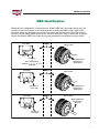
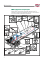
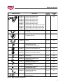
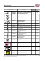
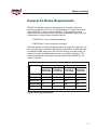
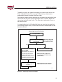
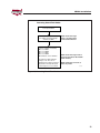
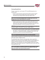
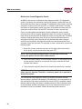
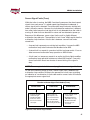
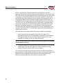
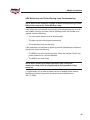
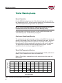
MBS-2
Installation Guide
AUGUST 2002
Heavy Duty Trailer ABS
by Wabash National
®
Notes, Cautions, and Warnings
This manual contains Notes, Cautions, and Warnings in addition to the
assembly instructions.
Notes: Provide additional comments to help with installation and set up.
Cautions: Provide notification of situations that can cause damage to
machinery and tools.
Warnings: Provide alerts to situations that can cause personal injury or
death.
Please take the time to read and understand this manual before beginning
assembly.
CAREFULLY FOLLOW THE SAFETY AND OPERATING INSTRUCTIONS
IN THIS MANUAL.
Due to a policy of continuous product improvement, we reserve the right to
make changes at any time, without notice, in prices, materials, colors,
specifications, equipment, models, and availability. Some photos and
drawings in this manual contain optional equipment. Since some information
may have been updated since the time of printing, please check with your
Wabash dealer for complete details.
© 2002 Wabash Technology Corp. All rights reserved. No portion of these
materials may be reproduced, stored, or transmitted without prior written
approval of Wabash National.
Wabash is an equal opportunity employer. M/F/V/H
MBS-2 Installation
®
MBS Identification
Before service or diagnostics is performed on a Wabash MBS unit, the system design must be
verified. Do not rely on labels or verbal descriptions to identify the MBS system. Refer to the
illustration below and compare the marking in the lower right-hand corner of the ECM with the
location(s) of the wheel speed sensor wire or cable on the trailer’s axle(s). Make sure to properly
identify the Wabash MBS; flash codes and system components are different for each system.
MBS-1
Top of ECM
+
No Marking
or
One of the Following:
Numbers "1", "2", "3", "4" or "5"
in this Area.
Wheel Speed Sensor
Wire Goes Into
Backing Plate
MBS-1P
Top of ECM
+
The Letter "P"
in this Area.
Wheel Speed Sensor
Wire Location
Wheel Speed Sensor
Wire Goes Into
Backing Plate
MBS-2
Top of ECM
Wheel Speed Sensor
Cable Location
+
Wheel Speed Sensor
Wire Location
Wheel Speed Sensor
Wire Goes Into
Axle Tube
The Letter "P"
in this Area.
281UX040
i
MBS-2 Installation
®
Contents
Wabash MBS-2 ABS Introduction . . . . . . . . . . . . . . . . . . . . . . . . . . . . . . . . 1
MBS-2 System Components . . . . . . . . . . . . . . . . . . . . . . . . . . . . . . . . . . . . 2
General Air Brake Requirements . . . . . . . . . . . . . . . . . . . . . . . . . . . . . . . . . 5
ABS . . . . . . . . . . . . . . . . . . . . . . . . . . . . . . . . . . . . . . . . . . . . . . . . . . . . . . . . . 6
Key Dates . . . . . . . . . . . . . . . . . . . . . . . . . . . . . . . . . . . . . . . . . . . . . . . . . 6
ABS Design Requirements . . . . . . . . . . . . . . . . . . . . . . . . . . . . . . . . . . . . 6
Type of ABS Required for Trailers . . . . . . . . . . . . . . . . . . . . . . . . . . . . . . 6
Power Requirements for ABS . . . . . . . . . . . . . . . . . . . . . . . . . . . . . . . . . . 7
ABS Malfunction Lamp . . . . . . . . . . . . . . . . . . . . . . . . . . . . . . . . . . . . . . . 7
Location . . . . . . . . . . . . . . . . . . . . . . . . . . . . . . . . . . . . . . . . . . . . . . . . . . 7
Color and Labeling . . . . . . . . . . . . . . . . . . . . . . . . . . . . . . . . . . . . . . . . . . 8
Intensity and Photometric Requirements . . . . . . . . . . . . . . . . . . . . . . . . . 8
Power Line Carrier (PLC) . . . . . . . . . . . . . . . . . . . . . . . . . . . . . . . . . . . . . 8
Applications . . . . . . . . . . . . . . . . . . . . . . . . . . . . . . . . . . . . . . . . . . . . . . . . . . 9
Electrical System . . . . . . . . . . . . . . . . . . . . . . . . . . . . . . . . . . . . . . . . . . . . 12
Pneumatic System . . . . . . . . . . . . . . . . . . . . . . . . . . . . . . . . . . . . . . . . . . .13
Installation of Electrical System . . . . . . . . . . . . . . . . . . . . . . . . . . . . . . . . 14
Power and Sensor Cables . . . . . . . . . . . . . . . . . . . . . . . . . . . . . . . . . . . 14
MBS-2 Cable Options . . . . . . . . . . . . . . . . . . . . . . . . . . . . . . . . . . . . . . .14
Circuit Requirements . . . . . . . . . . . . . . . . . . . . . . . . . . . . . . . . . . . . . . .20
Malfunction Lamp and Malfunction Lamp Diagnostic Switch . . . . . . . . . 20
Pneumatic System . . . . . . . . . . . . . . . . . . . . . . . . . . . . . . . . . . . . . . . . . . .21
MBS-2 Location and Mounting . . . . . . . . . . . . . . . . . . . . . . . . . . . . . . . . 21
Plumbing Instructions . . . . . . . . . . . . . . . . . . . . . . . . . . . . . . . . . . . . . . .22
Relay Valve . . . . . . . . . . . . . . . . . . . . . . . . . . . . . . . . . . . . . . . . . . . . . . .24
Active Wheel Speed Sensors . . . . . . . . . . . . . . . . . . . . . . . . . . . . . . . . . 26
ABS System Diagnostics . . . . . . . . . . . . . . . . . . . . . . . . . . . . . . . . . . . . . . 27
Initial System Checkout . . . . . . . . . . . . . . . . . . . . . . . . . . . . . . . . . . . . . 27
Pneumatic Diagnostics . . . . . . . . . . . . . . . . . . . . . . . . . . . . . . . . . . . . . . 27
Electrical Diagnostics . . . . . . . . . . . . . . . . . . . . . . . . . . . . . . . . . . . . . . .27
Troubleshooting The System . . . . . . . . . . . . . . . . . . . . . . . . . . . . . . . . . . . 28
Entering the flash code diagnostic mode . . . . . . . . . . . . . . . . . . . . . . . . 29
Suitable Light Tester . . . . . . . . . . . . . . . . . . . . . . . . . . . . . . . . . . . . . . . . 29
Current Faults . . . . . . . . . . . . . . . . . . . . . . . . . . . . . . . . . . . . . . . . . . . . . 30
Stored Faults . . . . . . . . . . . . . . . . . . . . . . . . . . . . . . . . . . . . . . . . . . . . . 32
Clearing Stored Faults . . . . . . . . . . . . . . . . . . . . . . . . . . . . . . . . . . . . . . 34
Malfunction Lamp Diagnostic Switch . . . . . . . . . . . . . . . . . . . . . . . . . . . 36
In-Axle Wheel Speed Sensor and Reverse Detect Feature . . . . . . . . . . 38
Sensor Signal Faults (Trace) . . . . . . . . . . . . . . . . . . . . . . . . . . . . . . . . . 41
ABS Malfunction and Trailer Warning Lamp Troubleshooting . . . . . . . . 43
Trailer Warning Lamp . . . . . . . . . . . . . . . . . . . . . . . . . . . . . . . . . . . . . . . . . 44
Normal Operation . . . . . . . . . . . . . . . . . . . . . . . . . . . . . . . . . . . . . . . . . . 44
Continuous Brake Apply Warning . . . . . . . . . . . . . . . . . . . . . . . . . . . . . . 44
Wheel End Temperature Warning . . . . . . . . . . . . . . . . . . . . . . . . . . . . . . 44
Accessing Trailer Warning Lamp Codes . . . . . . . . . . . . . . . . . . . . . . . . 45
Glossary . . . . . . . . . . . . . . . . . . . . . . . . . . . . . . . . . . . . . . . . . . . . . . . . . . . . 47
ii
MBS-2 Installation
®
Wabash MBS-2 ABS Introduction
The Wabash National Modular Brake System –2 (MBS-2) is Wabash’s second
generation Trailer Antilock Brake System. All MBS-2 controllers incorporate
the new PLC (power line carrier) data link that permits tractor to trailer
communications. In addition MBS-2 systems incorporate the new Wabash
active wheel speed sensor based on Hall Effect technology. The use of this
new sensor adds several new advantages:
• Mounting the sensor inside the hubcap provides a protected environment
as well as a fixed location for the sensor and magnet. This reduces fleet
maintenance by avoiding excessive gap issues associated with the
traditional VR sensor.
• Ability to detect when the trailer is moving in reverse. The ECM reads the
reverse signal and provides output drives that can be used to light a back
up light or to raise a self steering lift axle.
• Ability to read temperature at the wheel ends. If excessive wheel-end
temperature is detected, the ECM lights a warning lamp and also
transmits a warning signal over the PLC bus.
1
MBS-2 Installation
®
MBS-2 System Components
Wabash’s MBS-2 system includes unique ABS components as well as
interfacing with standard trailer components (see Figure 1). Refer to Figures 2
and 3 for part number and description of Wabash parts.
PCM/ECM
4-Pin Deutsch
DTM Series
Connector
Malfunction Lamp
Connector
Power Cable
Auxiliary
Warning Lamp
(location may
vary)
J560
Connector
Diagnostic
Switch
Malfunction
Lamp
Axle
Feed Through
Gladhand
R-12 Relay Valve
Spring Brake
Control Valve
ABS Axle Hubcap
ABS
In-Axle
Speed
Sensor
Roadside
Curbside
281UX023
Figure 1, Wabash MBS-2 Antilock Brake System
2
MBS-2 Installation
®
Component Item
Description
Quantity
Required
Supplied
in Kit
1
yes
1
no
10800316
10800317
2S-1M w/168" Power Cable
2S-1M w/30" Power Cable
10800318
10800319
2S-2M w/168" Power Cable
2S-2M w/30" Power Cable
10800320
10800321
4S-1M w/168" Power Cable
4S-1M w/30" Power Cable
10800315
10800324
4S-2M Side-by-Side w/168" Power Cable
4S-2M Side-by-Side w/30" Power Cable
10800322
10800323
4S-2M Axle-by-Axle w/168" Power Cable
4S-2M Axle-by-Axle w/30" Power Cable
14401905
MBS-2 Accessory Cable Extension
114" Long
10600482
ABS Hub Cap for In-Axle Sensor with
TP Spindle (6-hole)
2 or 4
yes
10600483
Gasket
2 or 4
yes
10800294
Spindle Extension Adapter for In-axle
Sensor/Aluminum Hub
(use with aluminum hubs only)
2 or 4
no
10800282
Curbside In-Axle Speed Sensor
1 or 2
yes
10800283
Roadside In-Axle Speed Sensor
1 or 2
yes
10600526
Freeze Plug
2 or 4
yes
BLT00722
Speed Sensor Mounting Bolt
(standard hubs)
2 or 4
yes
BLT00511
Speed Sensor Mounting Bolt
(aluminum hubs only)
Mounting Bolt Wave Washer
(standard hubs)
2 or 4
yes
2 or 4
yes
WSH00153
Mounting Bolt Lockwasher
(aluminum hubs only)
2 or 4
yes
10800291
Curbside In-axle Speed
Sensor Harness
1 or 2
yes
10800292
Roadside In-axle Speed
Sensor Harness
1 or 2
yes
WSH00152
281UX031
Figure 2, MBS-2 System Components
3
MBS-2 Installation
®
Component Item
Bolt 1/4-20 x 3-1/2" Grade 8 (1M System)
Bolt 1/4-20 x 5-1/2" Grade 8 (2M System)
Nut 1/4-20 Nylon Insert Locknut
Washer 1/4" SAE Flat
2
2
2
2
yes
yes
14401359
ABS Wiring Harness
1
yes
14401744
ABS Malfunction Lamp
Harness w/Diagnostic
Switch
1
yes
14200428
Yellow ABS Malfunction
Lamp
Green TL-30 Series Trailer Warning Lamp
Red TL-30 Series Trailer Warning Lamp
1
yes
1
no
TO READ STORED FAULT
PRESS THREE TIMES
(HOLD 3RD PRESS FOR
THREE SECONDS)
X4
TO CLEAR STORED FAULTS
PRESS FOUR TIMES
(HOLD 4TH PRESS FOR
THREE SECONDS)
X3
FLASH THREE TIMES
CURBSIDE SENSOR SIGNAL
(FRONT CURBSIDE ON 4 SENSOR SYSTEMS)
X4
FLASH FOUR TIMES
CURBSIDE SENSOR CONNECTION
(FRONT CURBSIDE ON 4 SENSOR SYSTEMS)
X5
FLASH FIVE TIMES
ROADSIDE SENSOR SIGNAL
(FRONT ROADSIDE ON 4 SENSOR SYSTEMS)
X6
FLASH SIX TIMES
ROADSIDE SENSOR CONNECTION
(FRONT ROADSIDE ON 4 SENSOR SYSTEMS)
FLASH SEVEN TIMES
CURBSIDE REAR SENSOR SIGNAL
X8
FLASH EIGHT TIMES
CURBSIDE REAR SENSOR CONNECTION
2) SYSTEMS WITH 2 SENSORS DO NOT UTILIZE
FLASH CODES 7-10 AND SENSORS MAY BE
LOCATED ON EITHER FRONT OR REAR AXLE
X9
FLASH NINE TIMES
ROADSIDE REAR SENSOR SIGNAL
X 10
FLASH TEN TIMES
ROADSIDE REAR SENSOR CONNECTION
X 11
FLASH ELEVEN TIMES
SECONDARY PCM FAULT
X 12
FLASH TWELVE TIMES
PRIMARY PCM FAULT
NOTE
MBS-2
X 14
FLASH FOURTEEN TIMES
LOW VOLT AGE TO ABS
X 15
FLASH FIFTEEN TIMES
ELECTRONIC CONTROL MODULE
4S SYSTEMS ONLY
X7
1) SYSTEMS WITH 1 PCM DO NOT UTILIZE FLASH
CODE 11
TM
14200018
Closed Back Malfunction
Lamp Grommet
1*
yes
12S00475
MBS-2 Mounting Bracket
(optional)
1
yes
14A00049
Straight Malfunction Lamp
Mounting Bracket
—
no
14A00050
90° Malfunction Lamp
Mounting Bracket
—
no
12900570
Relay Valve
1
yes
25000945
MBS-2 Flash Code Decal
1
yes
25000985
MBS-2 Enhanced Function Decal
1
yes
25000984
MBS-2 Reverse Notice Decal
1
yes
2S AND 4S SYSTEMS
TO READ CURRENT FAULTS
PRESS TWO TIMES
(HOLD 2ND PRESS FOR
THREE SECONDS)
X3
Supplied
in Kit
FLASH CODE QUICK REFERENCE
(ALLOW ONE SECOND BETWEEN PRESSES)
X2
Quantity
Required
BLT00650
BLT00732
NUT00007
WSH00010
14200623
14200002
DIAGNOSTIC SWITCH INPUT
Description
TRAILER ANTI-LOCK BRAKE SYSTEM
A PRODUCT OF WABASH NATIONAL
DECAL PART NUMBER: WN#25000945
TRAILER WARNING LAMP (TWL)
MBS-2 ENHANCED FUNCTIONALITY
FLASH CODE QUICK REFERENCE
DIAGNOSTIC SWITCH INPUT
X2
BLINK 2 TIMES
CONTINUOUS BRAKE APPLY
X4
BLINK 4 TIMES
RS FRONT BEARING TEMPERATURE
(ALLOW ONE SECOND BETWEEN PRESSES)
X2
TO READ CURRENT FAULTS
PRESS TWO TIMES
(HOLD 2ND PRESS FOR
THREE SECONDS)
X3
TO READ STORED FAULT
PRESS THREE TIMES
(HOLD 3RD PRESS FOR
THREE SECONDS)
X4
TO CLEAR STORED FAULTS
PRESS FOUR TIMES
(HOLD 4TH PRESS FOR
THREE SECONDS)
X5
BLINK 5 TIMES
CS FRONT BEARING TEMPERATURE
X6
BLINK 6 TIMES
RS REAR BEARING TEMPERATURE
X7
BLINK 7 TIMES
CS REAR BEARING TEMPERATURE
NOTE
DIAGNOSTIC SWITCH IS OPTIONAL ON TWL.
REFER TO MBS-2 MANUAL IF NOT PRESENT.
DECAL PART NUMBER: WNC#25000985
NOTICE
THIS TRAILER IS EQUIPPED
WITH A REVERSE
DETECTION SYSTEM.
BACKUP LIGHTS AND/OR
ALARM WILL ACTIVATE
WHEN VEHICLE IS MOVING
IN REVERSE.
DECAL PART NUMBER: WNC#25000984
* Two grommets required when installing the trailer warning system.
Figure 3, MBS-2 System Components
4
281UX024
MBS-2 Installation
®
General Air Brake Requirements
FMVSS-121 identifies minimum requirements for air brake systems on
commercial vehicles built in the U.S. (Requirements in Canada are covered
under CMVSS-121 and are virtually identical.) These regulations cover
requirements for new construction. Once put into operation, proper use and
maintenance is covered under standards such as:
• FMCSR 393 – Covers required equipment
• FMCSR 396 – Covers inspection and repair
The requirements for spring brake performance and operation, reservoir size
and air timing have not been changed with the introduction of ABS. Because
the addition of ABS components can have an affect on air brake timing, it is
important to verify acceptable performance on new ABS installations. The
maximum application and release times permitted under FMVSS-121 are
shown in Figure 4.
Release Time (mSec)
Apply Time (mSec)
From pedal
movement to
reach 60 PSIG
From pedal
movement to
reach 60 PSIG
From pedal
movement to
reach 5 PSIG
From pedal
movement to
reach 5 PSIG
Brake Chamber
50 CI Reservoir
Brake Chamber
50 CI Reservoir
Initial Condition 0 PSIG
0 PSIG
95 PSIG
5 PSIG
Towing Trailer
500
500
1000
1000
Converter Dolly 550
550
1100
1000
Single Trailer
N/A
1200
N/A
Measured at
600
281UX032
Figure 4, Air Timing Requirements
5
MBS-2 Installation
®
ABS
Key Dates
March 1, 1997 Tractors must be equipped to provide full time power to
trailers.
March 1, 1998 Newly manufactured trailers must be equipped with ABS.
Some special use cases are exempt. (Refer to FMVSS-121
for specific details.)
April 1, 2000
ABS required on newly manufactured Canadian Vehicles
March 1, 2001 Trailer malfunction lamp is required in the tractor cab.
March 1, 2008 Trailer mounted malfunction lamp no longer required.
ABS Design Requirements
Under FMVSS-121, an approved ABS must automatically control the degree
of rotational wheel slip during braking by:
1. Sensing the rate of angular rotation of the wheels.
2. Transmitting signals regarding the rate of wheel angular rotation to one or
more controlling devices which interpret those signals and generate
responsive controlling output signals.
3. Transmitting those controlling signals to one or more modulators which
adjust brake actuating forces in response to those signals.
Type of ABS Required for Trailers
ABS control is required on trailers as follows:
• Full Trailers – Direct ABS Control is required on at least one front and
one rear axle.
• Semi Trailers and Dollies – Direct ABS Control is required on at least
one axle.
Direct Control refers to an axle that is equipped with wheel speed sensors and
is controlled by a modulator valve or valves in response to the wheel speed
sensor signals. If this valve(s) also controls the brakes of another axle(s) that
does not have sensors, the axle(s) is referred to as an indirectly controlled
axle(s).
6
MBS-2 Installation
®
Power Requirements for ABS
For trailers built after March 1 of 1998, the trailer wiring system must provide
two sources of power for the antilock system.
1. Full-time power (when ignition is on) must be provided by the tractor. This
full-time power source may be shared with other trailer circuits. The SAE
J560 Blue (AUX) circuit is commonly used as the full-time power source.
In other cases, a separate ISO 3731 connector is provided.
2. Brake light power. This input provides a source of backup power for cases
where an older tractor (without full-time power) is used to tow a trailer or
in case of a failure of the permanent power source.
Industry standards (TMC RP-137 and SAE2247) require that the tractor
provide at least 10 amps at 12 volts at the trailer end of the SAE J560 or ISO
cable on all ABS power circuits. Suppliers of Trailer ABS have agreed to
provide for proper antilock brake operation down to a minimum of 8.5 volts.
The ABS malfunction lamp will light if voltages drop too low to maintain reliable
solenoid operation.
Wabash National antilock systems operate at voltages down to 7.0 volts.
Current requirements are approximately 330 milliamps per control unit and
1.25 amps per PCM.
ABS Malfunction Lamp
Rules for the location, color, labeling, intensity and photometrics for external
ABS malfunction lamps have been established by the National Highway
Transportation Safety Administration (NHTSA). These requirements are
effective as of March 1, 1998.
Location
The lamp mounting location shall be near the left side rear of the trailer, no
closer than 150 mm (5.9 inches) and not more than 600 mm (23.6 inches)
from the rear red side marker indicator lamp. On a converter dolly, the lamp
mounting location shall be on a permanent structure of the dolly at least
375 mm (14 inches) above the road surface. After March 1st, 2001 a second
ABS malfunction lamp must be located in the cab.
7
MBS-2 Installation
®
Color and Labeling
The malfunction indicator lamp must be yellow in color and identified with the
letters “ABS” to distinguish the lamp from other yellow side markers. The
letters may be on the lens, on the lens housing, or on the trailer itself, near
the lamp.
Intensity and Photometric Requirements
The external ABS malfunction indicator lamp must conform to SAE-J592
JUN92. Trailers shall use a combination clearance/side marker lamp marked
with a “PC” or “P2”. These lamps offer a widely diffused beam pattern
throughout a full 180-degree left and right range.
Power Line Carrier (PLC)
In order to meet the (March 2001) requirement to provide a tractor-mounted
trailer ABS malfunction lamp, the industry has adopted power line carrier
(PLC) technology. The use of a power-line-carrier permits transmission of data
between tractors and trailers without adding wires or connectors. Data is
transmitted as a series of high frequency chirps that appear on the ABS fulltime power line (the blue wire). The chirps vary in frequency between 100K Hz
and 400K Hz. The PLC signals are transmitted between trailer ABS control
units and tractor ABS control units. The tractor ABS unit has an additional
output signal that controls the cab-mounted trailer ABS
malfunction lamp.
The cab-mounted trailer ABS malfunction lamp:
• Lights to indicate a bulb check at start-up
• Remains lit at start-up if a fault code is set
• Will turn OFF after two seconds if the trailer is disconnected
• Lights during vehicle operation to indicate a fault has occurred.
In order for PLC to function, tractors and trailers must both be equipped with
PLC versions of ABS. All Wabash National MBS-2 systems manufactured after
March 1, 2001 are PLC capable.
8
MBS-2 Installation
®
Applications
The performance of the Wabash MBS-2 ABS depends upon proper installation
of all components. Trailer suspension, axle configuration, and other brake
components will affect the level of ABS performance.
The “Sensed” and the “Controlled” axles must be considered prior to
installation of the MBS-2. Wabash recommends the following guideline for
typical MBS-2 installations.
When locating the sensors on the tandem, choose the axle that locks up first
during hard braking. Typically, the front axle tends to lock up first on spring
suspension trailer applications. On air suspension systems, the axles tend to
lock up at the same time, so it is recommended that the rear axle be sensed
because of the added stability.
9
MBS-2 Installation
®
SPRING SUSPENSION
SENSED AXLE
SENSED AXLE
MBS-2 #10800316
CONTROLLED AXLE
SENSED AXLE
AIR SUSPENSION
2S-1M
MBS-2 #10800316
CONTROLLED AXLE
SENSED AXLE
MBS-2 #10800316
MBS-2 #10800316
CONTROLLED AXLES
CONTROLLED AXLES
SENSED
AXLE
SENSED
AXLE
MBS-2 #10800317
Air Suspended
Dollies Not Commonly
Available
CONTROLLED AXLE
CONTROLLED AXLE
SENSED
AXLE
MBS-2 #10800317
SENSED
AXLE
MBS-2 #10800317
MBS-2 #10800317
Air Suspended
Dollies Not Commonly
Available
CONTROLLED AXLES
CONTROLLED AXLES
2S-2M
SPRING SUSPENSION
SENSED AXLE
SENSED AXLE
SENSED AXLE
MBS-2 #10800318
CONTROLLED AXLE
One valve
each side
One valve
each side
MBS-2 #10800318
CONTROLLED AXLE
SENSED AXLE
MBS-2 #10800318
CONTROLLED AXLES
AIR SUSPENSION
One valve
each side
MBS-2 #10800318
CONTROLLED AXLES
One valve
each side
281UX013
Figure 5, Wabash MBS-2 Application Chart
10
MBS-2 Installation
®
SPRING SUSPENSION
SENSED AXLES
AIR SUSPENSION
4S-1M
SENSED AXLES
MBS-2 #10800320
MBS-2 #10800320
CONTROLLED AXLES
CONTROLLED AXLES
SENSED AXLES
SENSED AXLES
MBS-2 #10800320
CONTROLLED AXLES
SPRING SUSPENSION
SENSED AXLES
CONTROLLED AXLES
4S-2M Side Control
MBS-2 #10800315
CONTROLLED AXLES
One valve
each side
AIR SUSPENSION
One valve
each side
CONTROLLED AXLES
SENSED AXLES MBS-2 #10800315
CONTROLLED AXLES
SENSED AXLES
Air Suspended
Dollies Not Commonly
Available
SENSED AXLES MBS-2 #10800315
SENSED AXLES MBS-2 #10800315
SPRING SUSPENSION
MBS-2 #10800320
CONTROLLED AXLES
4S-2M Axle Control
MBS-2 #10800322
CONTROLLED
AXLE
CONTROLLED AXLE
Contact customer service for assistance when installing
ABS on units with axle spreads that exceed 11 feet.
One valve
each side
AIR SUSPENSION
SENSED AXLES
MBS-2 #10800322
CONTROLLED
AXLE
CONTROLLED AXLE
Contact customer service for assistance when installing
ABS on units with axle spreads that exceed 11 feet.
281UX012
Figure 6, Wabash MBS-2 Application Chart
11
MBS-2 Installation
®
Electrical System
The Antilock Control Module (ACM) consists of an Electronic Control Module
(ECM) and a Pneumatic Control Module (PCM) combined as one unit.
However, they are individually field replaceable. The wheel sensor, malfunction
lamp, and power harness circuits are connected to the ECM.
PCM/ECM
4-Pin Deutsch
DTM Series
Connector
Malfunction Lamp
Connector
Auxiliary
Warning Lamp
(location may
vary)
Power Cable
Diagnostic
Switch
ABS
Malfunction
Lamp
J560
Connector
Axle
Feed Through
ABS Axle Hubcap
ABS In-Axle
Speed Sensor
Roadside
Curbside
281UX028
Figure 7, Typical Electrical System Layout
12
MBS-2 Installation
®
Pneumatic System
The PCM contains the pneumatic solenoids that physically control pressure in
the service line to the relay valve. The 3/8" service line enters and exits the
PCM through integrated quick connect fittings. The PCM also incorporates a
quick exhaust valve that minimizes delays during brake release and helps
purge contaminants that may enter the service control line.
PCM/ECM
R-12 Relay Valve
Gladhand
Spring Brake
Control Valve
281UX027
Figure 8, Typical Pneumatic Layout for a 2M System
13
MBS-2 Installation
®
Installation of Electrical System
Power and Sensor Cables
One power cable, one or two sensor cables, and one accessory cable are
integrated into the MBS-2. The power cable runs to the Weather Pack 5-way
connector on the trailer. The sensor cables terminate in three-pin connectors
that mate with the 3-pin active speed Sensor Cable. The accessory cable
terminates in a Deutsch 4-pin DTM series connector.
MBS-2 Cable Options
The MBS-2 can be configured with either a long or short power cable. Refer to
the system component charts on page 3 and 4 for specific system and part
number information.
The short power cable is typically used with fixed bogies.
The long power cable is typically used with sliding bogies. Route the power
cable with the slider hoses to the trailer frame.
NOTE: The long cable can also be used on fixed bogies if required.
14
MBS-2 Installation
®
ECM
PCM
Wheel
Sensor
Accessory
Power
281UX025
Figure 9, MBS-2 Components and Connectors
15
MBS-2 Installation
®
Front
R
R
MBS-2 2S-1M
In-Axle Sensor
Cable Routing
S
S
10800283
Roadside
Left
MBS-2
Roadside
In-Axle
Sensor
Grey
Connector
Plugs Into
the ABS Power Cable
Accessory
Cable
Roadside
Sensor
Cable
Curbside
Sensor
Cable
Grommet
Grommet
Curbside
In-Axle
Sensor
Axle Plug
Wave
Washer
Black
Connector
Bolt
Sensor
Cable
C
Route Sensor Cable
As Shown
S
C
S
Front
10800282
Curbside
Right
281UX011
Figure 10, MBS-2 In-Axle Sensor Cable Routing for 2S-1M Systems
16
MBS-2 Installation
®
Front
R
R
MBS-2 2S-2M
In-Axle Sensor
Cable Routing
S
S
10800283
Roadside
Left
MBS-2
Roadside
In-Axle
Sensor
Grey
Connector
ABS Cable
Plugs Into
the ABS Power Cable
Accessory
Cable
Roadside
Sensor
Cable
Curbside
Sensor
Cable
Grommet
Grommet
Curbside
In-Axle
Sensor
Axle Plug
Wave
Washer
Black
Connector
Bolt
Sensor
Cable
C
Route Sensor Cable
As Shown
S
C
S
Front
10800282
Curbside
Right
281UX033
Figure 11, MBS-2 In-Axle Sensor Cable Routing for 2S-2M Systems
17
MBS-2 Installation
®
Front
R
R
MBS-2 4S-1M
In-Axle Sensor
Cable Routing
S
S
10800283
Roadside
Left
MBS-2
Roadside
In-Axle
Sensor
Grey
Connector
Roadside
Sensor
Cable
Grey
Connector
ABS Cable
Plugs Into
the ABS Power Cable
Curbside
Sensor
Cable
Accessory
Cable
Grommet
Curbside
In-Axle
Sensor
Wave
Washer
Axle Plug
Bolt
Grommet
Black
Connector
Front
C
S
C
S
10800282
Curbside
Right
Sensor
Cable
Route Sensor Cable
As Shown
281UX010
Figure 12, MBS-2 In-Axle Sensor Cable Routing for 4S-1M
18
MBS-2 Installation
®
Front
R
R
MBS-2 4S-2M
In-Axle Sensor
Cable Routing
S
S
10800283
Roadside
Left
MBS-2
Roadside
In-Axle
Sensor
Grey
Connector
Roadside
Sensor
Cable
ABS Cable
Plugs Into
the ABS Power Cable
Accessory
Cable
Grommet
Grey
Connector
Curbside
Sensor
Cable
Curbside
In-Axle
Sensor
Wave
Washer
Axle Plug
Bolt
Grommet
Black
Connector
Front
C
S
C
S
10800282
Curbside
Right
Sensor
Cable
Route Sensor Cable
As Shown
281UX005
Figure 13, MBS-2 In-Axle Sensor Cable Routing for 4S-2M
19
MBS-2 Installation
®
Circuit Requirements
The solenoid valves used in the Wabash MBS products allow higher airflow
and require less voltage and current than most trailer ABS systems. For a
nominal 12-volt supply, current consumption is about 1.25 amperes maximum
during ABS activity. Satisfactory operation is available down to 7 volts. The
MBS-2 minimizes trailer issues caused by inadequate voltage (typically found
in 3-trailer units).
Malfunction Lamp and Malfunction Lamp Diagnostic Switch
NOTE: The malfunction lamp bulb must be incandescent. Always replace
the bulb with another incandescent bulb of the same value.
A diagnostic switch is located near the ABS malfunction lamp. A malfunction
lamp harness incorporating this switch is included in the MBS-2 kit.
NOTE: While this feature is desirable, it is not essential. Diagnostic flash
codes can also be activated from the tractor cab via the ignition switch.
Trailer Wall
Malfunction Lamp
Mounting Bracket
X
H
TS
UL
ITC
FA
T
SW EN
IC BETWE RREN R
ES FO
ST OND
TIM S
NO SEC AD CU
O ES
T
AG
TWD PR S)
UL
ND
DI LOW ONE TO RES 2N
FA
ES
CO
PR LD SE
EDES R
E
OR
(HO
RE
ST E TIMS FO
TH
AD RE ES
TS
RE TH PR S)
UL
FA
TO ESS 3RDCOND
ED
PR LD SE
OR ES R
E
(HO
ST TIM FO
RE
S
R
TH
EA UR ES
CL FO PR S)
TO ESS 4THCOND
SH
PR LD SE
E
FLA
(HO
E
RE
ILIZ
TH
(AL
X
2
3
X
4
X
E
TE T UT
ILIZ
NO NO
UT
T Y BELE
DO
M
NO MA AX
DO S AR
1 PC
S ORRE
H
OR NS
WIT
NSD SE T OR
MS
2 SEAN ON
STE11
H 0 FR
R
SY
WITS 7-1
1) CODE
HE
MS DE EIT
STE COON
SY SH
TM
2) FLA TED
CA
LO
Power
Cable
Connector
Malfunction Lamp
Ground Wire
Malfunction
Lamp Pigtail
STE
SY AL
E ION
AK
NAT
BR
K ASH
OC
WAB
TI-L
OF
AN T
R DUC
M
ILE
PRO
TRAA
L
DE
X
X
X
X
X
X
X
X
X
X
4
5
6
7
8
9
10
11
12
14
15
4
RB T
TIMOR
STE
CU ON
UR NS E ON
SY
(FR
FO SE SID
L OR
NA NS
SH E RB
)
SID
MS
FLA
ES SIG4 SE
RB T CU
OR
N STE
CU ON
E TIM
NS E ON
TIO SY
(FR
FIV SE SID
EC OR
SH E AD
NN NS
SID
CO4 SE
FLA
AD T RO
ES
RO ON
ON
TIMNSOR
E
L
(FR
SIX SE SID
NA
SH E AD
N
SIG
SID
FLA
TIO
AD T RO
ES OR
EC
RO ON
TIMSENS
NN
N
(FR
CO
VE AR
SE RE
ES NSOR
L
SH E
NA
TIM SE
SID
FLA
N
RB
HT AR
SIG
CU
TIO
EIG RE
OR
EC
ES NS
SH E
NN
SID
SE
FLA
RB
E TIM
CO
AR
CU
NIN RE
OR
SH E
ESSENS
SID
FLA
TIM
AD
AR
RO
TENRE
SH E
ES LT
SID
FLA
TIM
AD
N FAU
RO
VE M
PC
ES
ELE Y
SH AR
E TIMLT
ND
FLA
CO
ES
ELV FAU
SE
TWPCM
TIM
N S
SHRY
LE
TEE AB
FLA
DU
IMA
UR E TO
PR
ES L MO
FO AG
TIM
SH LT
N NTRO
VO
FLA
W
TEECO
LO
FIF
SHRONIC
FLACT
ELE
RT
945
000
#25
: WN
ER
MB
NU
PA
CA
MBS-2
Flash Code
Decal
Malfunction Lamp
(Must be Incandescent)
Malfunction Lamp
Power Wire
20
X
M
S
B
Malfunction Lamp
Diagnostic Switch
Figure 14, ABS Malfunction Lamp Installation
-2
E
NC
RE
)
MS
FE
STE
RE
SY
K
L OR
IC
)
NS
QU ESSIGNA
SE
MS
DE E TIMORON 4
N STE
NS E
TIO SY
CO THRE
SE SID
EC OR
H
E
)
NS
AS FLASHSIDCURB ES CONN
SE
MS
3
T
S)
SSE
PRE
4S SYSTEMS ONLY
PU
2S AND 4S SYSTEMS
FL
IN
281UX026
MBS-2 Installation
®
Pneumatic System
MBS-2 Location and Mounting
The MBS-2 can be located some distance from the relay valve. The air line
connecting the PCM to the relay valve should be 3 to 5 feet in length. This
allows some mounting flexibility, provides good ABS performance, and
complies with brake application and release timing requirements.
Mount the MBS-2 using two grade 8 bolts WNC part number BLT00650
(1/4-20 x 3-1/2") for 1M systems, BLT00732 (1/4-20 x 5-1/2") for 2M systems.
NOTE: Use the grade 8 bolts included with the MBS-2 installation kit.
The bolts must be inserted from the bracket side when installing 2M systems.
An optional mounting bracket (WNC part number 12S00475) is available from Wabash.
The MBS-2 may also be mounted directly to a crossmember by drilling two
mounting holes on 5-3/8" centers.
Mounting Bracket
or Crossmember
Mounting
Bolt
PCM
Delivery
Port
PCM
ECM
Air Line
Tubing
Supply
Port
Washer
Nut
Air Line
Tubing
Exhaust
Port
281UX030
Figure 15, Typical MBS-2 Mounting
21
MBS-2 Installation
®
Plumbing Instructions
Install the MBS-2 as follows:
1. Select a suitable mounting location near the front of the bogie.
2. Install the MBS-2 in the blue service line (see Figure 16).
3. Connect the port marked “SUP” to the glad-hand side.
4. Connect the port marked “DEL” to the relay valve side.
NOTE: Because of volume considerations discussed later, the spring
brake valve may be supplied from either the “upstream” (glad-hand side)
or the “downstream” (relay side) of the MBS-2. Wabash recommends that
it be supplied from the downstream side to help purge contaminates
from the anti-compounding supply line.
IMPORTANT: When the Trailer Emergency Valve (TEV) is supplied
downstream of the MBS-2, the line from the MBS-2 must be routed
to the relay valve first, and from there, to the trailer emergency valve
(TEV). Circumstances where the TEV is supplied downstream of the
MBS-2 then 1/4" airline must be used from the R-12 to the TEV.
Wabash requires the following pneumatic plumbing:
1. From “DEL” of MBS-2, route 3/8" tubing to a tee at the relay valve.
2. From the tee at the top of the relay valve, route 1/4" tubing to the spring
brake valve anti-compounding port.
IMPORTANT: The line lengths are significant. The combined
volume in the two lines mentioned in steps 1 and 2 above must
equal the volume of between three and five feet of 3/8" tubing. The
volume of 1/4" tubing is about 40% that of 3/8" tubing of equal length.
Calculate tubing equivalents using the following formula:
Leq = equivalent length of the combined 3/8" and 1/4" tubes
L3/8 = actual length of 3/8" tubing
L1/4 = actual length of 1/4" tubing
Then:
Example:
3 feet of 3/8"
2.5 feet of 1/4"
Leq= 3 + 0.4 (2.5)= 4.0
281UX036
Leq = L3/8 + (0.4 x L1/4)
The air volume in the tubing after the MBS-2 is a significant performance
factor. Leq must be between three and five feet.
22
MBS-2 Installation
®
Preferred Plumbing
2M Side Control
Spring Suspension w/Slider
TEV
Supply
Service
MBS-2
Relay
Valves
Bulkhead
Feedthru
Spring
Brake
Gladhand
Service
Brake
Note: Actual Component Locations May Vary
Preferred Plumbing
2M Axle Control
Spring Suspension w/Slider
281UX014
TEV
Supply
Service
MBS-2
Relay
Valves
Bulkhead
Feedthru
Gladhand
Spring
Brake
Service
Brake
Note: Actual Component Locations May Vary
281UX016
Figure 16, MBS-2 “Downstream” Air Supply Configurations (Preferred Plumbing)
23
MBS-2 Installation
®
NOTE: If the plumbing cannot be accomplished within the five foot
maximum length, the relay valve can be fed directly with a 3/8" tube from
the “DEL” port of the MBS-2. The feed for the trailer spring brake valve
can be taken from a tee connection upstream of the MBS-2. Use a 3/8"
line to the Trailer Emergency Valve (TEV).
For this configuration, the volume of the line to the spring brake valve is not
included in the calculation.
Following these guidelines will usually result in an installation that complies
with application and release brake timing requirements. However, always
check application and release times for each configuration.
IMPORTANT: When the anti-compounding port of the Trailer
Emergency Valve (TEV) is plumbed in before the PCM the straight
through connection must be plumbed to the PCM and the branch
connection to the TEV. All airline used in this case can be 3/8" tubing
because the PCM does not exhaust this portion of the airline during an
ABS event. For this plumbing configuration, omit this length of airline
when calculating allowable tubing lengths.
Relay Valve
Provided that all brake application and release timing requirements are met, a
Bendix relay valve (WNC part number 12900570) is approved for all
applications. This valve is normally included with the MBS-2 installation kit.
IMPORTANT: Wabash National must approve all installations that
use other relay valves.
24
MBS-2 Installation
®
Alternate Plumbing
2M Side Control
Spring Suspension w/Slider
TEV
Supply
Service
MBS-2
Relay
Valves
Bulkhead
Feedthru
Spring
Brake
Gladhand
Service
Brake
Note: Actual Component Locations May Vary
Alternate Plumbing
2M Axle Control
Spring Suspension w/Slider
281UX015
TEV
Supply
Service
MBS-2
Relay
Valves
Bulkhead
Feedthru
Gladhand
Spring
Brake
Service
Brake
Note: Actual Component Locations May Vary
281UX017
Figure 17, MBS-2 “Upstream” Air Supply Configurations (Alternate Plumbing)
25
MBS-2 Installation
®
Active Wheel Speed Sensors
The new Wabash National wheel speed sensor incorporates an Application
Specific Integrated Circuit (ASIC) that contains two Hall cells and a
temperature sensor. The temperature sensor is used to infer wheel bearing
temperature. The use of the dual Hall Effect sensors allows detection of the
direction of the wheels by using a technique known as quadrature. The sensor
is mounted at the end of the trailer axle spindle and retained by a shoulder
bolt. When final assembly is complete, the sensor is setting well protected
within the hubcap. The sensor harness is located in the axle tube and exits
through a strain relief at the center of the tube. The Hall cells are triggered by
a series of magnetic poles embedded in a magnet ring that is pressed into a
unique Wabash National Hubcap. Use of the Wabash active sensor eliminates
the need for the traditional tone ring and mounting blocks. Wabash active
sensors are not adjustable, eliminating sensor out-of-adjustment issues.
IMPORTANT: The in-axle sensor is designed to interface with steel
hubs. When aluminum hubs are installed on the trailer, use a
Wabash Spindle Extension Adapter (10800294) at each sensor. The
aluminum hub is longer than a steel hub. This pushes the hubcap
interface on the aluminum hub outboard and causes misalignment
between the sensor pick-up and the magnet in the hubcap. The result is
that the ABS does not receive wheel speed information and the unit will
not do ABS and will not turn on the backup lamps! When the spindle
extension adapter is installed, longer sensor mounting bolts and lock
washers must be used as well. The part number for the longer bolt is
BLT00511. The part number for the washer is WSH00153. Using
aluminum hubs creates a more complex assembly, however Wabash
supports its use.
Use with
Aluminum
Hubs Only
OR
ABS
Hubcap
Gasket
Axle
Spindle
Bolt
Wave
Washer
In-Axle
Speed
Sensor
Spindle
Extension Adapter
(use with aluminum
hubs only)
Figure 18, In-Axle Speed Sensor and ABS Hubcap
26
281UX009
MBS-2 Installation
®
ABS System Diagnostics
Initial System Checkout
When the system is first powered up the ABS malfunction lamp will come ON
for two seconds then go OFF, indicating the system has passed all self-tests.
All MBS-2 units and optional features must pass operation checks before the
trailer is placed in service.
Pneumatic Diagnostics
The Wabash ABS system does not monitor the air system of the vehicle. For
example, if there is an air leak, kink in the line, or faulty relay valve, the ABS
malfunction lamp will not show a fault in the system. However, if a malfunction
in the air system arises and it cannot be determined if the ABS valve is
causing the problem, the ABS can simply be bypassed using a short length of
airline and two push-in unions. For example, if an unknown kink exists in the
control line and the brakes will not apply, simply remove the airlines from the
quick connect fittings on the ABS valve and insert the short length of airline
using the push-in unions. The system can then be reexamined without the
ABS affecting the system. If the brakes still do not apply it can then be
assumed that the ABS valve is not causing the problem.
Electrical Diagnostics
The malfunction lamp is an important tool when assessing the status of the
ABS system. When the system is operating properly the malfunction lamp will
illuminate briefly, then go OFF every time the system is powered up. If the
vehicle is stationary at power up, the lamp will remain ON for two seconds and
the PCM will perform a functional test causing an audible clicking or puffing. If
the vehicle is mobile at power up, the lamp will remain ON for one second and
the PCM self-test will be aborted. The PCM self-test is performed at each
stationary power up to give the operator an audible sign that everything is
performing normally.
The ABS system receives power from the stop lamp circuit (pin 4 of J560
connector – red) and the auxiliary circuit (pin 7 of J560 connector – blue). This
means the system will operate on a tractor with or without the auxiliary circuit
powered at tractor ignition. In a situation where the system only receives
power from the stop circuit, the malfunction lamp will illuminate briefly each
time the brakes are applied and the PCM self test will be performed at each
stationary brake application.
Upon power up, if the system behaves differently than described above, such
as the malfunction lamp remains illuminated or does not come ON at all, follow
the instructions in the next section to determine the cause of the problem.
27
MBS-2 Installation
®
Troubleshooting The System
DIAGNOSTIC SWITCH INPUT
FLASH CODE QUICK REFERENCE
(ALLOW ONE SECOND BETWEEN PRESSES)
X4
FLASH FOUR TIMES
CURBSIDE SENSOR CONNECTION
(FRONT CURBSIDE ON 4 SENSOR SYSTEMS)
X5
FLASH FIVE TIMES
ROADSIDE SENSOR SIGNAL
(FRONT ROADSIDE ON 4 SENSOR SYSTEMS)
X6
FLASH SIX TIMES
ROADSIDE SENSOR CONNECTION
(FRONT ROADSIDE ON 4 SENSOR SYSTEMS)
X7
FLASH SEVEN TIMES
CURBSIDE REAR SENSOR SIGNAL
1) SYSTEMS WITH 1 PCM DO NOT UTILIZE FLASH
CODE 11
X8
FLASH EIGHT TIMES
CURBSIDE REAR SENSOR CONNECTION
2) SYSTEMS WITH 2 SENSORS DO NOT UTILIZE
FLASH CODES 7-10 AND SENSORS MAY BE
LOCATED ON EITHER FRONT OR REAR AXLE
X9
FLASH NINE TIMES
ROADSIDE REAR SENSOR SIGNAL
X 10
FLASH TEN TIMES
ROADSIDE REAR SENSOR CONNECTION
X 11
FLASH ELEVEN TIMES
SECONDARY PCM FAULT
X 12
FLASH TWELVE TIMES
PRIMARY PCM FAULT
X 14
FLASH FOURTEEN TIMES
LOW VOLT AGE TO ABS
X 15
FLASH FIFTEEN TIMES
ELECTRONIC CONTROL MODULE
X2
X3
TO READ STORED FAULT
PRESS THREE TIMES
(HOLD 3RD PRESS FOR
THREE SECONDS)
X4
TO CLEAR STORED FAULTS
PRESS FOUR TIMES
(HOLD 4TH PRESS FOR
THREE SECONDS)
NOTE
TM
MBS-2
4S SYSTEMS ONLY
FLASH THREE TIMES
CURBSIDE SENSOR SIGNAL
(FRONT CURBSIDE ON 4 SENSOR SYSTEMS)
2S AND 4S SYSTEMS
X3
TO READ CURRENT FAULTS
PRESS TWO TIMES
(HOLD 2ND PRESS FOR
THREE SECONDS)
TRAILER ANTI-LOCK BRAKE SYSTEM
A PRODUCT OF WABASH NATIONAL
DECAL PART NUMBER: WN#25000945
281UX041
Figure 19, MBS-2 Flash Code Decal
28
MBS-2 Installation
®
Entering the flash code diagnostic mode
Fault identification is provided via flashes of the ABS malfunction lamp. To
enter the flash code diagnostic mode, it must be possible to power the
auxiliary circuit. On March 1997 and newer tractors, this circuit is switched
with the ignition. Alternately, a suitable light tester may be used.
Suitable Light Tester
When using a light tester to power any ABS system, supply power directly
from a battery, not a charger. The charger may remain connected to the
battery to keep the battery charged, but the charger can not be used as the
power source. See figure 20.
Faults are categorized in two types:
• Current Faults – Faults that are active when the system is powered up,
causing the malfunction lamp to remain illuminated. All current faults
become stored faults after they are repaired.
• Stored Faults – Faults that were current faults at one time, but are no
longer active and allow the malfunction lamp to go OFF at power up.
Typically they may be caused by intermittent problems that only occur
when the vehicle is moving.
Both, stored faults and current faults can be identified using the ABS flash code
system.
12V
Battery
Battery
Charger
+
Switch
Panel
+
J560 Trailer Connector
7. Blu (Continuous ABS Power)
6. Brn (Tail and license plate lamps)
5. Grn (Right Turn Signal)
4. Red (Stop Lamps/ABS)
-
-
3. Yel (Left Turn Signal)
2. Blk (Clearance, Side Marker & Ident Lamps)
1. Wht (Ground Return to Towing Vehicle)
281UX006
Figure 20, Typical Trailer Light Test Unit Suitable for Use with ABS
29
MBS-2 Installation
®
Current Faults
To access the flash code identification for a current fault, turn all power OFF to
the ABS and perform the following steps.
1. Power the stop lamp circuit (red) and allow power to remain ON this
circuit until the flash code has been identified (see step 3 below). The
malfunction lamp will light with the stop lamps and remain ON (if the lamp
goes out, there are no current faults).
NOTE: This circuit can be powered with a suitable light tester or by
pulling down on the trailer brake lever in the cab.
2. Power the auxiliary circuit (blue) for one second, then power down for one
second, then power back up and allow the power to remain ON until the
flash code has been identified (power ON two times).
NOTE: This circuit can be powered with a suitable light tester or by
turning the ignition ON and OFF on newer model tractors.
3. The malfunction lamp will begin flashing a code. The code is identified by
the number of times the lamp illuminates.
NOTE: After the first flash sequence, the lamp will turn OFF briefly then
repeat the flash sequence. This will continue for one minute allowing
time to reach the trailer ABS light and record the number of flashes.
30
MBS-2 Installation
®
To identify the fault, the code will correspond to a specific fault found in the
Flash Code Identification Table on page 37. Before any maintenance is
performed, disconnect all power from the system.
In the unlikely event that more than one fault is present, the malfunction lamp
will not turn OFF at power up after the original fault is repaired. Repeat the
above steps to identify other faults. This allows repair personnel to focus on
one fault at a time.
If a stored fault exists, it will be identified after you clear the last stored fault
(see Clearing Stored Faults). Current faults will always be displayed first and
cannot be cleared.
Accessing Current Fault Codes
Turn all power OFF
Power the stop lamp circuit (red).
Does the malfunction lamp light
and remain ON?
YES
NOTE: Power with a light
tester or by pulling down
on the trailer brake lever.
NO
Power the auxiliary circuit (blue):
• One second ON
• One second OFF
• ON until flash code is identified
The malfunction lamp will begin
flashing a code. The code is
identified by the number of times the
lamp flashes. The lamp will repeat
the flash sequence for one minute.
Malfunction lamp does not turn OFF,
at power up, after the original fault
is repaired
There are no current faults.
NOTE: Power with a light tester or
by turning the ignition ON and OFF
(newer models).
NOTE: Current fault codes cannot be
cleared until the cause is corrected.
Repeat
Procedure
281UX018
Figure 21, Accessing Current Fault Codes
31
MBS-2 Installation
®
Stored Faults
To access the flash code identification for a stored fault, turn all power OFF to
the ABS and perform the following steps.
NOTE: This procedure should only be required during annual routine
maintenance or when there is an intermittent problem that does not
show up at stationary power up. For example, if a wheel locks up for an
extended period of time because of a foundation brake malfunction.
1. Power the stop lamp circuit (red) and allow power to remain ON this
circuit until the flash code has been identified (see step 3 below). The
malfunction lamp will light with the stop lamps and then turn OFF.
NOTE: This circuit can be powered with a suitable light tester or by
pulling down on the trailer brake lever in the cab.
2. Power the auxiliary circuit (blue) for one second, power down for one
second, power back up for one second, power down for one second, then
power back up and allow the power to remain ON until the flash code has
been identified (power ON three times).
NOTE: This circuit can be powered with a suitable light tester or by
turning the ignition ON and OFF on newer model tractors.
3. The malfunction lamp will begin flashing a code. The code is identified by
the number of times the lamp illuminates.
NOTE: After the first flash sequence, the lamp will turn OFF briefly then
repeat the flash sequence. This will continue for one minute allowing
time to reach the trailer ABS light and record the number of flashes.
To identify the fault code, refer to the Flash Code Identification Table on page 37.
Before any maintenance is performed, all power must be disconnected from
the system.
If more than one stored fault exists, it will be identified after you clear
each fault.
32
MBS-2 Installation
®
Accessing Stored Fault Codes
Turn all power OFF
Power the stop lamp circuit (red).
The malfunction lamp will light
and then turn OFF
Power the auxiliary circuit (blue):
• One second ON
• One second OFF
• One second ON
• One second OFF
• ON until flash code is identified
The malfunction lamp will begin
flashing a code. The code is
identified by the number of times the
lamp flashes. The lamp will repeat
the flash sequence for one minute.
NOTE: Power with a light
tester or by pulling down
on the trailer brake lever.
NOTE: Power with a light tester or
by turning the ignition ON and OFF
(newer models).
NOTE: If lamp does not flash, no
faults are present.
281UX019
Figure 22, Accessing Stored Fault Codes
33
MBS-2 Installation
®
Clearing Stored Faults
To clear a stored fault, turn all power OFF to the ABS and perform the
following steps:
1. Power the stop lamp circuit (red) and allow power to remain ON this
circuit until the faults have been cleared (see step 3 below). The
malfunction lamp will light with the stop lamps and turn OFF.
NOTE: This circuit can be powered with a suitable light tester or by
pulling down on the trailer brake lever in the cab.
2. Power the auxiliary circuit (blue) for one second, power down for one
second, power back up for one second, power down for one second,
power up for one second, power down for one second, then power back
up and allow the power to remain ON (power ON four times).
NOTE: This circuit can be powered with a suitable light tester or by
turning the ignition ON and OFF on newer model tractors.
3. The malfunction lamp will begin flashing rapidly for ten seconds signaling
the system is in the fault clear mode. The fault is actually cleared in the
first fraction of a second but the delay is designed to allow time for the
technician to confirm the fault clear mode was entered.
NOTE: This rapid flashing will occur even if no fault is present.
After the rapid flash sequence, the malfunction lamp will turn OFF and remain
OFF unless another stored fault exists.
The malfunction lamp will flash a fault code shortly after the rapid flash
sequence if more than one fault was stored in memory. After the appropriate
number of flashes, the lamp will turn OFF briefly, then repeat the flash
sequence. This will continue for one minute, giving personnel time to return
from the tractor cab to check the count. To identify the code, refer to the Flash
Code Identification Table.
NOTE: The ON and OFF periods for entering the above modes do not
have to be exactly one second. However, one should use slow and
deliberate motions when powering ON and OFF.
34
MBS-2 Installation
®
Clearing Stored Fault Codes
Turn all power OFF
Power the stop lamp circuit (red).
Malfunction lamp will light
and then turn OFF
Power the auxiliary circuit (blue):
• One second ON
• One second OFF
• One second ON
• One second OFF
• One second ON
• One second OFF
• ON
NOTE: Power with a light
tester or by pulling down
on the trailer brake lever.
NOTE: Power with a light
tester or by turning the
ignition ON and OFF
(newer models).
The malfunction lamp will flash
rapidly (even if no fault is present).
Does the malfunction lamp turn
OFF and remain OFF?
YES
No other stored faults exist
NO
Other stored faults exist.
The malfunction lamp will flash the
next stored fault code then turn OFF,
then repeat the flash sequence for
one minute
Repeat
Procedure
281UX020
Figure 23, Clearing Stored Fault Codes
35
MBS-2 Installation
®
Malfunction Lamp Diagnostic Switch
All MBS-2 units have a malfunction lamp diagnostic switch. This diagnostic
switch is located in the malfunction lamp wiring harness, behind the base rail
where the malfunction lamp is mounted. The diagnostic switch works much like
turning the auxiliary circuit ON and OFF on a newer model tractor. Pressing
the button on the diagnostic switch two times will produce the same result as
turning the auxiliary circuit ON and OFF two times to view a current fault.
There are subtle differences between using the diagnostic switch and the
auxiliary circuit. When using the diagnostic switch, for instance, the warning
lamp will not illuminate while the diagnostic switch is being pressed. Therefore,
instead of holding the button down on the last desired cycle (equivalent to
leaving the auxiliary circuit ON after the last desired cycle when using the
auxiliary circuit method), the diagnostic switch must be released after three
seconds to view the fault code. For example, to view a stored fault, perform the
following steps:
1. Power the system using the stop lamp circuit (red) and/or the auxiliary
circuit (blue), until the malfunction lamp goes OFF.
NOTE: This circuit can be powered with a suitable light tester or by
turning the ignition ON for newer model tractors.
2. Press and hold the button for one second, release it for one second, press
for one second, release for one second, then press and hold for three
seconds then release.
3. The malfunction lamp will then flash a stored fault code if one is present.
NOTE: The malfunction lamp diagnostic switch will not operate once
wheel speed is detected. Therefore, a stationary power up is required to
activate the switch.
The malfunction lamp diagnostic switch is an exclusive Wabash National
feature and has significant advantages. The technician is in close proximity to
the malfunction lamp where all information from the ECM is received. A quick
reference decal listing fault codes is located adjacent to the malfunction lamp
for convenience. Another advantage is that it’s not important which circuit is
powered or if both are powered, thereby eliminating some confusion.
36
MBS-2 Installation
®
Flash Code
Fault
Comments
3
Curbside front sensor signal fault.
Check hubcap and sensor for proper attachment to the wheel end.
Check wiring to sensor.
4
Curbside front sensor connection fault.
Check all harnesses to the sensor for damage.
5
Roadside front sensor signal fault.
Check hubcap and sensor for proper attachment to the wheel end.
Check wiring to sensor.
6
Roadside front sensor connection fault.
Check all harnesses to the sensor for damage.
7
Curbside rear sensor signal fault.
Check hubcap and sensor for proper attachment to the wheel end.
Check wiring to sensor.
8
Curbside rear sensor connection fault.
Check all harnesses to the sensor for damage.
9
Roadside rear sensor signal fault.
Check hubcap and sensor for proper attachment to the wheel end.
Check wiring to sensor.
10
Roadside rear sensor connection fault.
Check all harnesses to the sensor for damage.
11
Secondary PCM fault.
Separate the ECM from the secondary PCM. Check that the connector
and socket are secured together properly. If the fault persists, replace
the secondary PCM.
12
Primary PCM fault.
Separate the ECM from the primary PCM. Check that the connector
and socket are secured together properly. If the fault persists, replace
the primary PCM.
14
Low voltage to ABS.
Check tractor and trailer wiring on auxiliary and stop lamp circuits.
Check tractor battery and charging system.
15
Electronic Control Module failure.
Replace the ECM.
NOTE: A two-sensor system does not contain 7 through 10 blink codes and a one-PCM system does not include the 11-blink code.
The primary PCM is the PCM closest to the Electronic Control Module (ECM) and the secondary PCM is the furthest from the ECM.
281UX029
Figure 24, Flash Code Identification Table
37
MBS-2 Installation
®
In-Axle Wheel Speed Sensor and Reverse Detect Feature
The MBS-2 system incorporates an active Hall effect in-axle wheel speed
sensor in place of the passive VR wheel speed sensor used in all other ABS
systems. This wheel speed sensor is mounted on the axle end using the
freeze plug to secure it in place while the magnet is located inside the hubcap.
The use of this technology provides several advantages. The sensor can
detect reverse motion of the vehicle. This allows the ABS to control backup
lights or any other accessory needed to be turned ON or OFF during reverse
motion. Other advantages are that the sensor and wiring harnesses are
located in a protected environment and sensor gap issues simply do not apply.
The sensor also contains a temperature sensor that is used to alert the operator
and maintenance personnel of an elevated bearing temperature. This is done
with the use of an optional secondary trailer warning lamp. The location of this
lamp is also optional according to customer preference and legal
requirements. See pages 44 and 45 for more information.
The reverse detect feature activates based on input from two sensors. On a
four-sensor system this means that the feature is activated from the front axle
sensors input. Both wheels must be rotating in reverse at a speed less than
fifteen miles per hour and auxiliary power must be present in order for the
feature to be activated. The reverse detect feature is not activated immediately
when the vehicle moves backward for the first time to avoid turning on the
lamps when the vehicle inadvertently drifts backward at a stoplight. There is a
2.5-second delay built into the system to avoid this. Once the vehicle is
moving in reverse for 2.5 seconds the backup lights will come on and remain
on until the vehicle is stopped for ten seconds or the operator pulls forward for
more than five seconds. However, they will illuminate immediately every time
the vehicle is reversed until the vehicle exceeds 10 miles per hour while
moving forward or the vehicle moves forward for more than five seconds. Then
the reverse detection system is reset back to the 2.5-second delay.
NOTE: When performing an installation of MBS-2 with backup lamps,
always check backup lamp operation before releasing the unit for
service.
In the event the reverse lights do not illuminate when they should, here are
some troubleshooting steps to follow:
1. Make certain there are no current faults on the system. (The malfunction
lamp will go out at power up.) If a current fault exists, correct the problem
and recheck the operation of backup lamps.
38
MBS-2 Installation
®
2. Check for auxiliary power at the J560 connector from the tractor (center
pin). If a light tester is used, be sure to supply voltage to the tester using a
battery. A battery charger may be used to keep the battery charged but
may not be connected to the tester if a battery is not present. If there is
no power on the center pin, the backup feature will not operate. Auxiliary
power should also be present at the ABS power connector, pin B of the
Weather Pack 5-way located in front of the slider hose bracket mounted to
the trailer underbody. If no power is present, check the connections of the
ABS power cable in the J560 connector. The red wire should be on the
bottom pin (red) the blue wire should be on the center pin (blue) and the
white wire should be on the ground circuit (white). If power is present at
the J560 connector, check the ABS harness for damage.
IMPORTANT: When performing the troubleshooting step below
spin the wheels in a slow, deliberate manner.
3. The reverse lamp circuit receives power from the accessory cable (the
eighteen-inch long harness exiting the ECM housing and terminating in a
Deutsch four-socket DTM06-4S connector). When holding the connector
with the sockets facing you and the connector clasp at the top, the
sockets are numbered one through four counterclockwise, starting in the
top left position. Socket one is the backup circuit. Using a voltage tester,
confirm that 12 VDC is present on socket one when the wheels are
rotated in the reverse direction. Socket two works the opposite way, power
is present full time until the wheels are reversed. Socket two can be
checked for power to confirm the ABS is receiving adequate power. If
power is not present on socket one when the wheels are reversed, but is
present on socket two, the system is not receiving a wheel speed signal
from one of the sensors. If this is the case, a sensor signal fault should be
present on the system (a three or five flash fault). Check sensor wiring for
damage.
4. If power exists in all the above areas, there is a problem with the backup
harness (the harness between the ABS and the backup lamps). Check
the pins in the mating plug on the backup harness to be sure they are not
bent or missing, and verify the lamps have sufficient ground.
39
MBS-2 Installation
®
5. The following troubleshooting scheme should only be performed after all
the above troubleshooting steps have been completed. If in a rare case
an in-axle sensor harness is defective, with the speed signal and ground
leads crossed, the MBS-2 will not see this as a fault until the trailer is
moving. Once moving, the system turns on the warning lamp as it is
receiving an inadequate signal from the wheel with the defective harness.
IMPORTANT: When performing the troubleshooting step below
spin the wheels in a slow, deliberate manner.
To troubleshoot this type of problem, power the auxiliary circuit and check for
12 VDC on pin two of the 4-pin Deutsch connector on the accessory cable.
(See figure 29 on Page 46 “MBS-2 Electrical Schematic”) Voltage should be
present at power up. Locate the wheels on the front axle of a four-sensor
system or the sensed wheels of a two-sensor system. Spin the wheels in
opposite directions, one forward and the other in the reverse direction, for ten
seconds. The power on pin two of the accessory cable should drop to zero. If
it does not the wheel that was spun in the reverse direction has a defective
harness. If power does drop to zero spin the wheels forward to reestablish
power on pin two. Spin the wheels in the opposite direction again, only spin
the wheel that was spinning in the reverse direction before in the forward
direction and spin the wheel that was spinning in the forward direction before
in the reverse direction for ten seconds. As before if the power does not drop
to zero then the wheel spinning in the reverse direction has the defective
harness. If the power still drops to zero after both above cases have been
performed then the problem exists in the backup harness, not the in-axle
harnesses.
NOTICE
THIS TRAILER IS EQUIPPED
WITH A REVERSE
DETECTION SYSTEM.
BACKUP LIGHTS AND/OR
ALARM WILL ACTIVATE
WHEN VEHICLE IS MOVING
IN REVERSE.
DECAL PART NUMBER: WNC#25000984
281UX007
Figure 25, Backup Light Decal
40
MBS-2 Installation
®
Sensor Signal Faults (Trace)
While the trailer is moving, the MBS-2 continually compares the wheel speed
signals from each sensor. If a wheel speed signal becomes inadequate, a
sensor signal fault is detected. The malfunction lamp illuminates and the fault
code is stored in memory. However, the fault detection mechanism is different
from other faults because a bad signal fault is only detected when the trailer is
moving. All other faults are electrical in nature and are detected at power up.
Because of this difference, sensor signal faults result in slightly different
malfunction lamp behavior. The concept of a fault “trace” helps explain how the
malfunction lamp functions. A fault trace is between a current fault and a
stored fault.
• A current fault represents an existing fault condition. It causes the ABS
malfunction lamp to be illuminated and disables trailer ABS.
• A stored fault is a record of a previous fault that no longer exists. It has no
affect on normal malfunction lamp operation or ABS function.
• A fault trace is a temporary record of an earlier fault that slightly modifies
malfunction lamp operation but does not affect ABS function. It normally
clears itself within about two minutes of normal driving if the signal is
okay.
NOTE: The concept of a fault trace only applies to sensor signal faults.
On the next stationary power up after a sensor signal fault is detected, the
malfunction lamp remains ON due to the presence of a fault trace, providing
an indication of a malfunction. A flash code read for current faults will indicate
the appropriate sensor signal fault.
Function of Sensor Signal Fault Codes (Trace)
Current Faults
• Illuminate the ABS
malfunction light
• Disable trailer ABS
• Cannot be cleared
• Become stored faults
after repair.
Trace Faults
Stored Faults
• Sensor faults only
• Set temporary code
• Can clear themselves
• Do not disable ABS
• Become Stored faults
after clearing themselves.
• Were originally current
or trace faults
• Do not illuminate the
ABS malfunction light
• Do not disable ABS
• Stored codes can
be cleared.
281UX021
Figure 26, Trace Sensor Signal Codes
41
MBS-2 Installation
®
Unlike a regular fault, on the next stationary power up after the fault is
repaired, the lamp will remain ON because the fault trace is still present. Once
the trailer moves, and assuming both signals are now present, the malfunction
lamp will go out and ABS function will be available. However, a trace of the
fault still remains, even though the fault no longer exists as a current fault. If
the trailer immediately stops and goes through a power OFF/ON cycle, the
malfunction lamp will again remain illuminated until the trailer starts to move.
The ECM still is not satisfied that the sensor signal fault is absolutely gone,
taking about two minutes of normal driving above 5 mph before the trace of
the fault is completely cleared with a restored signal. After the next power
OFF/ON cycle, the malfunction lamp behaves as normal, illuminating for two
seconds, then turning OFF. The fault trace is gone and will be replaced by a
stored fault in memory.
The fault trace can also be cleared in the shop by either of two methods:
• Jack up and spin only the wheel that had the faulty signal. The
malfunction lamp will go OFF immediately and return to normal behavior.
This approach does not clear the stored sensor signal fault. It is still
available as a record, just like any other stored fault.
NOTE: All other wheels must remain stationary while spinning the wheel
that introduced the fault.
• The second method of clearing the fault trace in the shop is to restore the
sensor signal, then clear the signal fault. The fault trace will also be
cleared. Proceed as usual to clear any stored fault.
The trace fault management philosophy provides an excellent compromise. It
assures there is a fault indication on the next power up after sensor signal fault
detection. After the signal has been restored, normal malfunction lamp
behavior resumes within about two minutes of normal driving.
42
MBS-2 Installation
®
ABS Malfunction and Trailer Warning Lamp Troubleshooting
NOTE: Refer to the schematic on page 46 when troubleshooting the ABS
Malfunction Lamp or the Trailer Warning Lamp.
If the lamp does not illuminate at power up but the solenoids perform the selftest (audible sound) or air brake sounds (chuffing sound) with treadle valve
applied, check the following:
• The lamp power harness may be disconnected.
• The bulb may have a bad ground connection.
• The malfunction lamp may be faulty.
If the lamp does not illuminate on power up and the solenoids do not perform
the self-test, check the following:
• The MBS-2 may not be receiving power. Check the Weather Pack 5-way
power connector for a loose connection.
• The MBS-2 may have failed.
NOTE: When checking for proper operation, keep in mind the
malfunction lamp circuit is only powered for two seconds at initial
power up.
If a replacement part or other customer service is needed, please contact
the Wabash National Corporation Customer Service Department at
765-771-5389.
43
MBS-2 Installation
®
Trailer Warning Lamp
Normal Operation
Like the ABS Malfunction Lamp, the Trailer Warning Lamp will come ON for
two seconds then go OFF at each stationary power up. This indicates that the
Trailer Warning bulb and wiring harness are operational.
NOTE: On units manufactured June, 2002 or later, either an LED or an
incandescent bulb can be used for the Trailer Warning Lamp.
If the lamp does not illuminate at power up, refer to ABS Malfunction and
Trailer Warning Lamp Troubleshooting on page 43.
Continuous Brake Apply Warning
The continuous brake apply warning is a feature of the MBS-2 that signals the
operator if the treadle valve on the tractor has become stuck open, resulting in
the brakes being applied without the operator’s knowledge. The warning is
initiated based on vehicle speed and the duration the stop circuit is powered.
The graph below illustrates when the warning becomes active. The line
represents when the warning is triggered. See Figure 27.
Wheel End Temperature Warning
The wheel end temperature warning is initiated when the wheel speed sensor
detects a rise in temperature on one of the wheel ends.
Refer to Figure 28 for a description of trailer warning lamp flash codes and
their causes.
Time (minutes)
5
4
3
2
1
1
10
20
30
40
50
Vehicle Speed (mph)
Figure 27, Continuous Brake Apply Warning Graph
44
60
70
80
90
100
281UX022
MBS-2 Installation
®
Accessing Trailer Warning Lamp Codes
Trailer warning lamp fault codes are accessed in the same manner as the
ABS system faults. Access trailer warning lamp fault codes as follows:
• To view current faults, refer to page 30.
• To view stored faults, refer to page 32.
• To clear stored faults, refer to page 34.
TRAILER WARNING LAMP (TWL)
MBS-2 ENHANCED FUNCTIONALITY
FLASH CODE QUICK REFERENCE
DIAGNOSTIC SWITCH INPUT
X2
BLINK 2 TIMES
CONTINUOUS BRAKE APPLY
X4
BLINK 4 TIMES
RS FRONT BEARING TEMPERATURE
X5
BLINK 5 TIMES
CS FRONT BEARING TEMPERATURE
X6
BLINK 6 TIMES
RS REAR BEARING TEMPERATURE
X7
BLINK 7 TIMES
CS REAR BEARING TEMPERATURE
(ALLOW ONE SECOND BETWEEN PRESSES)
X2
TO READ CURRENT FAULTS
PRESS TWO TIMES
(HOLD 2ND PRESS FOR
THREE SECONDS)
X3
TO READ STORED FAULT
PRESS THREE TIMES
(HOLD 3RD PRESS FOR
THREE SECONDS)
X4
TO CLEAR STORED FAULTS
PRESS FOUR TIMES
(HOLD 4TH PRESS FOR
THREE SECONDS)
NOTE
DECAL PART NUMBER: WNC#25000985
281UX008
Flash Code
Condition
Comments
2
Continuous brake apply
Check air system on service brakes or electrical wiring to
stop lamp circuit.
4
Roadside front bearing temperature
Check roadside front wheel end for overheated bearings.
5
Curbside front bearing temperature
Check curbside front wheel end for overheated bearings.
6
Roadside rear bearing temperature
Check roadside rear wheel end for overheated bearings.
7
Curbside rear bearing temperature
Check curbside rear wheel end for overheated bearings.
281UX034
Figure 28, Trailer Warning Lamp Flash Code Identification Table and Decal
45
MBS-2 Installation
®
4-Pin
Deutsch
DTM Series
Connector
1
2
Trailer
Side
Power
Cable
ECM Side
1-Back Up Circuit
2-ACC High
3-Trailer Warning Lamp
4-ACC Low
B
A
4
3
E
D
C
A-Stop Lamp Power (Red)
B-Auxiliary Power (Blue)
C-Not Used
D-ABS Malfunction Lamp (W/G)
E-Ground (White)
Ground (White)
Trailer
Warning
Lamp
Accessory Low
Accessory High
Switched 12V
Constant
Power From
Tractor (Blue)
12 3 4
Backup
Lamp
Extension
used
with most
slider bogie
applications
Accessory Cable
MBS-2
ECM
Stop Lamp
Power (Red)
Stop Lamp Power (Red)
Auxiliary Power (Blue)
Ground (White)
ABS Malfunction Lamp (Wht/Green)
Power Diagnostic Cable
Front Axle Sensor Harness
7-Pin
J560
Diagnostic Switch
Malfunction
Lamp Side
Diagnostic
Switch
Rear Axle Sensor
Harness
Trailer Mounted
ABS Malfunction Lamp
ECM
Inside Axle
Front
Axle Feed
Through
3-Pin Micropack
Harness
Side
3-Pin
Metripack
Front
Roadside
Sensor
Front
Curbside
Sensor
Rear
Roadside
Sensor
Rear
Axle Feed
Through
Rear
Curbside
Sensor
Axle Feed Through
In Axle Harness
In Axle Wheel Sensor
OR
281UX004
Figure 29, MBS-2 Electrical Schematic
46
MBS-2 Installation
®
Glossary
2S-1M
Two sensor, one modulator system.
2S-2M
Two sensor, two modulator system.
4S-1M
Four sensor, one modulator system.
4S-2M
Four sensor, two modulator system.
Axle-by-Axle Control
Axle-by-axle control is available only on 4S-2M
systems. Each sensed axle is controlled
independently based on wheel speeds from both
wheels on a single axle.
Side-by-Side Control
Side-by-side control is available only on 4S-2M
systems. Each side of the vehicle is controlled
independently based on wheel speeds from sensed
wheels on each side of the vehicle.
ACM
Antilock Control Module. Consists of ECM and
PCMs.
Current Faults
Faults that are active when the system is powered up
which cause the malfunction lamp to remain
illuminated.
ECM
Electronic Control Module.
Flash Code
A series of flashes of the malfunction lamp, providing
fault code identification.
Malfunction Lamp
Located on the rear driver side corner of the vehicle
just forward of the rear marker lamp, the malfunction
lamp verifies the system is functioning properly or
alerts the operator if a problem arises with the ABS.
Trailer Warning Lamp
Alerts the operator if a problem arises with a system
not related to the basic antilock function. For
example, elevated wheel end temperatures.
MBS-2
Wabash’s ACM that utilizes the in-axle wheel speed
sensor system, including backup control and wheel
end temperature monitoring.
PCM
Pneumatic Control Module.
47
MBS-2 Installation
®
Stored Faults
Faults that were current faults at one time, but are no
longer present and allow the malfunction lamp to go
out at power up.
Trace Fault
A temporary record of a previous fault that slightly
modifies malfunction lamp operation but does not
affect ABS function.
Wheel Speed Sensors Located either in the front and/or rear axle,
depending on the geometry of each particular
tandem, the wheel sensors receive wheel speed
information.
48
MBS-2 Installation
®
Notes
______________________________________________________________
______________________________________________________________
______________________________________________________________
______________________________________________________________
______________________________________________________________
______________________________________________________________
______________________________________________________________
______________________________________________________________
______________________________________________________________
______________________________________________________________
______________________________________________________________
______________________________________________________________
______________________________________________________________
______________________________________________________________
______________________________________________________________
______________________________________________________________
______________________________________________________________
______________________________________________________________
______________________________________________________________
______________________________________________________________
49
MBS-2 Installation
®
Notes
______________________________________________________________
______________________________________________________________
______________________________________________________________
______________________________________________________________
______________________________________________________________
______________________________________________________________
______________________________________________________________
______________________________________________________________
______________________________________________________________
______________________________________________________________
______________________________________________________________
______________________________________________________________
______________________________________________________________
______________________________________________________________
______________________________________________________________
______________________________________________________________
______________________________________________________________
______________________________________________________________
______________________________________________________________
______________________________________________________________
50
®
© 2002 Wabash Technology Corp.
PGI57281-0802