1
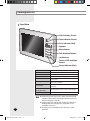
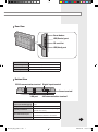
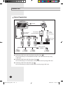
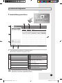
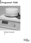
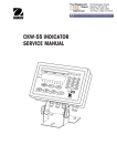
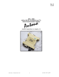
USER’S MANUAL MST-S3W S-NET mini E DB98-29360A(1) MST-S3W_IB_E_29359-1.indd 109 2008-03-10 ソタネト 2:13:45 Safety Precautions This installation manual describes how to install the S-NET mini. For installation of other optional accessories, refer to the appropriate installation manual. CAUTION Do not install the product where there’s combustible gas. - Potential risk of fire or explosion. Do not install the outdoor unit on an unstable place such as outer high wall of an apartment or building and on an outside terrace to avoid falls. - If the outdoor unit falls, it may cause personal injury or loss of property. Install the product with proper power supply. - Potential risk of fire or damage to the product. Do not connect power cable to a communication terminal. - Potential risk of fire or explosion. Consult the place of purchase or a contact center to disassemble or repair the product. - Potential risk of unit malfunction, water leakage, electric shock, or fire. Contact service center or dealer for installation. - Potential risk of fire or damage to the product. Do not use Benzene, Thinner or Clorox™. They may damage the surface of the unit and can create a risk or fire. E-2 MST-S3W_IB_E_29359-1.indd 2 2008-03-10 ソタネト 2:13:02 WARNING Do not put undue stress on the power cable or place heavy objects on it. - Damaged power cable may cause fire. Install the product on a hard and even place that can support its weight. - If the place cannot support its weight, the product may fall down and it may cause injury. Do not disassemble or reinstall the product on your own discretion. - Potential risk of electric shock or fire. Secure the installation plate tightly on the wall. - Potential risk of damage to the product. Install the product avoiding direct sunlight or heater, especially water. - Potential risk of electric shock or poor air conditioning. Never use a damaged power plug, power cable, or loosened power receptacle. - Potential risk of fire or electric shock. Do not give excessive shock to the air conditioner. - Potential risk of fire or unit malfunction. Do not yank the power cable and touch the power plug with wet hands. - Potential risk of fire or electric shock. If the power cable or cord is damaged, the manufacturer, a qualified service technician must replace it to avoid a potential risk. Do not install the product in areas exposed to oil or vapor. - Potential risk of product damage or malfunction. E-3 MST-S3W_IB_E_29359-1.indd 3 2008-03-10 ソタネト 2:13:03 Contents VIEWING THE PART ................................................................................................................ 6 FRONT VIEW ......................................................................................................................... REAR VIEW ........................................................................................................................... BOTTOM VIEW ..................................................................................................................... 6 7 7 BEFORE USE .............................................................................................................................. 8 SYSTEM ORGANIZATION .................................................................................................... 8 CHECK LIST .......................................................................................................................... 9 MAIN FUNCTION .................................................................................................................. 10 TERMS USED IN DMS ................................................................................................... 10 INTERFACE WITH LOWER LEVEL CONTROLLER ............................................................ 10 INDOOR UNIT CONTROL ................................................................................................ 10 SCHEDULE MANAGEMENT ............................................................................................. 10 ZONE MANAGEMENT ..................................................................................................... 11 SECURITY SETUP .............................................................................................................. 11 VIEW DVM INFORMATION ........................................................................................... 11 PEAK POWER MANAGEMENT ................................................................................. 11 OPERATIONAL MODES ..................................................................................................... 12 INDOOR UNIT USAGE RESTRICTION ................................................................................ 13 OTHERS ............................................................................................................................. 13 POWER MONITORING ...................................................................................................... 13 GETTING STARTED .............................................................................................................. 14 STARTING S-NET MINI .................................................................................................. 14 CONNECTING CENTRALIZED CONTROLLER AND THE TRANSMITTER ........................ 17 CONNECTING DMS ....................................................................................................... 17 MAIN DISPLAY ...................................................................................................................... 18 MAIN MENU .................................................................................................................... 18 INDOOR UNIT CONTROL .................................................................................................. 19 INDOOR UNIT CONTROL MENU ....................................................................................... 19 VIEWING BY ICON ............................................................................................................. 20 VIEWING BY LIST ............................................................................................................... 21 VIEWING BY FULL SCREEN ................................................................................................ 22 CONTROLLING INDIVIDUAL INDOOR UNIT ................................................................... 24 CONTROLLING MULTIPLE INDOOR UNITS .................................................................... 26 CONTROLLING ALL THE INDOOR UNITS ....................................................................... 27 SETTING UP THE TEMPERATURE LIMIT ......................................................................... 28 APPLYING THE TEMPERATURE LIMIT ............................................................................. 30 CANCELING THE TEMPERATURE LIMIT .......................................................................... 31 ENABLE WIRED/WIRELESS REMOTE CONTROL ............................................................... 32 DISABLE WIRED/WIRELESS REMOTE CONTROL ............................................................. 33 CHECKING TODAY’S SCHEDULE ..................................................................................... 34 SCHEDULE MANAGEMENT .............................................................................................. 35 SCHEDULE MANAGEMENT MENU ................................................................................ 35 CREATING NEW SCHEDULES ......................................................................................... 36 EDIT SCHEDULES .............................................................................................................. 42 DELETE SCHEDULES ........................................................................................................ 43 APPLY SCHEDULES .......................................................................................................... 44 STOP SCHEDULES ............................................................................................................ 45 STOP ALL SCHEDULES ..................................................................................................... 46 SAVING SCHEDULES ........................................................................................................ 47 OPENING SCHEDULE ....................................................................................................... 48 VIEWING SCHEDULE ........................................................................................................ 49 E-4 MST-S3W_IB_E_29359-1.indd 4 2008-03-10 ソタネト 2:13:03 ZONE MANAGEMENT......................................................................................................... 50 ZONE MANAGEMENT MENU ........................................................................................ CREATING A NEW ZONE ................................................................................................ DELETING A NEW ZONE ................................................................................................ RENAMING A NEW ZONE/INDOOR UNIT ..................................................................... MOVING A ZONE/INDOOR UNIT .................................................................................. MOVING AN INDOOR UNIT TO A DIFFERENT ZONE .................................................. INITIALIZE ZONE MANAGEMENT ................................................................................... SAVING ZONE MANAGEMENT ...................................................................................... OPENING ZONE MANAGEMENT ................................................................................... 50 51 52 53 54 55 56 57 58 SECURITY SETUP................................................................................................................... 59 SECURITY SETUP MENU ................................................................................................. 59 ENABLE/DISABLE PASSWORD ....................................................................................... 60 CHANGING PASSWORD ................................................................................................... 61 TRACKING ................................................................................................................................. 62 TRACKING MENU ............................................................................................................. 62 EXECUTE TRACKING ......................................................................................................... 64 VIEW DVM INFORMATION............................................................................................ 68 VIEW DVM INFORMATION ........................................................................................... 68 VIEW INDIVIDUAL DETAILED INFORMATION ................................................................ 69 VIEW ERROR LOG ............................................................................................................. 70 H/W SETUP ........................................................................................................................... 71 H/W SETUP MENU ....................................................................................................... 71 DATE/TIME SETUP ........................................................................................................... 72 BRIGHTNESS CONTROL .................................................................................................... 73 VOLUME CONTROL ........................................................................................................... 74 IP SETUP ............................................................................................................................ 75 VIEW VERSION .................................................................................................................. 76 STYLUS ADJUSTMENT ...................................................................................................... 77 POWER MANAGEMENT ..................................................................................................... 78 POWER MANAGEMENT MENU ..................................................................................... 78 PRIORITY CONTROL MODE ............................................................................................ 79 EDIT SETUP IN PRIORITY CONTROL MODE ................................................................. 81 CIRCULATION CONTROL MODE ................................................................................... 84 EDIT SETUP IN CIRCULATION CONTROL MODE .......................................................... 86 SET CLASS IN CIRCULATION CONTROL MODE ......................................................... 88 POWER MONITORING ..................................................................................................... 90 SYSTEM MANAGEMENT .................................................................................................... 93 SYSTEM MANAGEMENT MENU ..................................................................................... 93 COMMUNICATION SETUP ............................................................................................... 94 SYSTEM INITIALIZATION .................................................................................................. 95 DMS IP SETUP .............................................................................................................. 96 SYNCHRONIZE TIME ......................................................................................................... 99 SOFT KEYBOARD ............................................................................................................... 100 USING SOFT KEYBOARD .............................................................................................. 100 TROUBLE SHOOTING........................................................................................................ 102 APPENDIX .............................................................................................................................. 105 IP TERMINOLOGY .......................................................................................................... 105 E-5 MST-S3W_IB_E_29359-1.indd 5 2008-03-10 ソタネト 2:13:04 Viewing the Part Front View LAN indicator (Green) Data indicator (Green) Error indicator (Red) Speaker Menu button Soft keyboard button Lock button Power & LCD backlight button Power indicator (Red) Indicates communication status of internet Data indicator (Green) Indicates 485 communication status Error indicator (Red) Indicates error Speaker Sound can be heard through speaker Menu button Select menu Soft keyboard button Press this button to use the soft keyboard to enter text or number Lock button Restricts other people’s access by using password. Power & LCD Backlight button Turn On/Off the power and the LCD backlight. Power indicator (Red) Indicates on/off status Note For the longer use of your LCD, screen will automatically switch to screensaver (LCD backlight off) if there has not been any input for 5 minutes. Screensaver (LCD backlight off) will be off and the LCD backlight will turn on by pressing any button or tap anywhere on the LCD. Though your LCD backlight is off, S-NET mini is still in operation. E-6 MST-S3W_IB_E_29359-1.indd LAN indicator (Green) 6 2008-03-10 ソタネト 2:13:05 Rear View Reset button USB(Device) port SD card slot USB(Host) port Reset button Reset S-NET mini USB(Device) port Connect with other products set as host SD card slot Insert SD card in, to save or load data USB(Host) port Connect with other products set as device Bottom View RS232 communication terminal Digital input terminal Power terminal LAN port 485 communication terminal RS322 communication Connect with other RS232 communication terminal (For OS Debugging) device LAN port Connect with DMS Digital input terminal Connect with devices which outputs digital signal (Ex. Fire sensor) 485 communication port Connect with 485 communication terminal on Centralized controller or Transmitter Power terminal Connect with 12V adapter MST-S3W_IB_E_29359-1.indd 7 E-7 2008-03-10 ソタネト 2:13:05 Before Use System Organization S-NET mini DMS c Ethernet a Centralized controller PEAK Control Transmitter Power Meter Interface Module b Transmitter Transmitter Transmitter Demand Control Max. 32 units (DVM +) Connecting S-NET mini with Centralized controller. (Type a ) - You can control up to 16 Centralized controllers and 256 indoor units by using S-NET mini. Connecting S-NET mini with Transmitter. (Type b ) - You can control up to 16 Transmitters and 256 indoor units by using S-NET mini. Connecting S-NET mini with DMS (Type c ) - You can control up to 4 DMS and 256 indoor units by using S-NET mini. E-8 MST-S3W_IB_E_29359-1.indd 8 2008-03-10 ソタネト 2:13:06 Check List Checking the Power Cable. Press the Power button to turn on the S-NET mini. Check if the Power indicator turns red. If the Power indicator has not turned on, check the power terminal and make sure power cable is correctly connected. Checking the Indicators. Check if the LAN indicator and the Data indicator turns green. Check if the Error indicator turns red. If the Error indicator has turned red, check the power and communication cable connection. Checking the Connection Connection with DMS Make sure LAN cable is correctly connected to the LAN port. Make sure power terminal is correctly connected. Connection with Centralized controller/Transmitter Make sure communication cable is correctly connected to 485 communication terminal. Check the polarity of the 485 communication cable. When the polarity changes, communication will be unavailable. Make sure power terminal is correctly connected. E-9 MST-S3W_IB_E_29359-1.indd 9 2008-03-10 ソタネト 2:13:08 Main Function Terms Used in S-NET mini S-NET mini: A device that controls system air conditioner installed in a small and medium-sized buildings. It can be used with Centralized controller, Transmitter and DMS. DMS: Abbreviation for Data Management System. Centralized controller: Control system that has ability to control up to 16 groups. Transmitter: Transmits data between Centralized controller and the indoor units. Peak transmitter: Transmits PEAK control data from Demand controller and deliver data to DMS. DVM: Digital Variable Multi Air conditioning system (Outdoor unit) Demand control: Manages maximum power usage by getting the information from the power meter interface module. Interface with Lower Level Controller S-Net mini is an integrated management system which can be used with lower level controllers such as DMS, Centralized controller and Transmitter. These integrated management systems can control system air conditioner installed in small and medium sized buildings. Indoor Unit Control S-NET mini can remotely control the temperature, operation mode, fan speed on indoor units connected to DMS, Centralized controllers and Transmitters. Schedule Management S-NET mini can apply schedule and repeat them daily/weekly. You can select a schedule by Apply/Cancel command. Individual schedule can contain up to 10 events. (Daily repeat: Max.10 events, Weekly repeat: Max. 70 events) Item Schedule period Exception days Selected indoor units Event Content Starting and ending date of a schedule Set an exception day within a schedule period to ignore the schedule control Select indoor units to receive schedule control Set indoor unit operation modes - Indoor unit On time - Indoor unit Off time - Desired temperature - Control modes: Heat, Cool, Dry, Fan, and Auto - Enable/Disable remote control Remarks Maximum 10 events E-10 MST-S3W_IB_E_29359-1.indd 10 2008-03-10 ソタネト 2:13:08 Zone Management S-NET mini can control indoor units conveniently by using zone management system. Zone/Indoor name can be maximum 32 letters long. Special character or symbols (\, /, ;, *, ?, “, “, ‘, ’, <, >) cannot be used in a name. Each zone can contain maximum 64 indoor units. Security Setup To maintain security, you can set password on your S-NET mini. Password Enabled: You will need to enter the password to use the menu with the Lock ( ) icon. Password Disabled: You may use all the function in the main menu without any restrictions. View DVM Information You can check error log, connection status and cycle status. S-NET mini saves maximum 256 error logs. If the number of errors exceeds 256, only the latest 256 cases are stored by deleting the oldest error history. You can check device name, IP address, date of occurrence, current status, date resolved, and type of error from the error log. Device Type of an error Indoor unit Indoor unit communication error Indoor unit sensor related error Other errors Outdoor unit Outdoor unit communication error Piping inspection error Outdoor unit sensor related error Other outdoor unit related errors Solution Products such as the Centralized Controller Solution device related communication error PEAK Power Management S-NET mini can manage and monitor PEAK power through DMS that is connected to a PEAK transmitter. PEAK power management In case of temporary power usage reaching the PEAK power, the air conditioner restricts its use, such as changing its mode to Fan mode or cutting off the power, to minimize the power usage. S-Net mini controls and manages indoor units according to the alarm level provided by DMS to maintain the PEAK power. PEAK level is composed of 4 different levels from 0~3, and the DMS, connected to a PEAK control interface module, provide the PEAK level information. MST-S3W_IB_E_29359-1.indd 11 E-11 2008-03-10 ソタネト 2:13:08 Main Function Operational modes PEAK power management is operating in ‘No PEAK setup’, ‘Priority control mode’, or ‘Circulation control mode’. No PEAK setup: This is a factory default and the PEAK power management is not in operation. Priority control mode: PEAK power operation mode that assigns indoor units to Levels 1,2 and 3 or none and operates the respective indoor units when the power level at the peak interface module reaches anyone of the preset level. Priority of each indoor units can be set through the Web or with Upper level controller. Applied group PEAK level Level 0 No Peak power management Level 1 Peak power management on groups within priority level 1 group Level 2 Peak power management on groups within priority level 1 and 2 Level 3 Peak power management on groups within priority level 1~3 Circulation control mode: An energy saving function that operates each class in rotation according to the alert level at the peak interface module. The higher the alert level, the more classes will be put on energy-saving operation. Within the set Circulation period, indoor units in applied group will be restricted in its operation. When the Circulation period ends, next applied group will be restricted since PEAK power management will be active, and the indoor units in previous group will operate in the recent mode used. Applied group PEAK level Level 0 No Peak power management Level 1 Peak power management on groups within priority level 1 group Level 2 Peak power management on groups within priority level 1 and 2 Level 3 Peak power management on groups within priority level 1~3 E-12 MST-S3W_IB_E_29359-1.indd 12 2008-03-10 ソタネト 2:13:08 Indoor unit usage restriction S-NET mini should have DMS in connection with the PEAK control transmitter. When the indoor unit is operating in Dry/Cool/Auto, they will switch to Fan mode while PEAK power management is applied. When the indoor unit is operating in Heat mode, it will switch to ‘Fan mode’, ‘Power off’ or ‘Change set temperature(16ºC)’. (You can change these setting on S-NET mini.) If the indoor unit with its power off has been assigned to PEAK power management group and the user try to operate the indoor unit while PEAK power management is in active, indoor unit will automatically stop its operation. If the indoor unit operating in Fan mode has been assigned to PEAK power management group and the user try to change operation mode to Cool or Heat mode while in PEAK power management is in active, indoor unit will automatically switch its mode to Fan mode. In PEAK power management mode, ‘Turning on the indoor unit’ or ‘Changing operation mode to Cool/Auto/Dry’ will be restricted. In PEAK power management mode, ‘Turning on the indoor unit’ or ‘Changing operation mode to Cool/Auto/Dry’ within the schedule and all the other events will be ignored. ‘Turning on the indoor unit’ or ‘Changing operation mode to Cool/Auto/Dry’ through Centralized controller or Wired/Wireless remote controller while in PEAK power management mode will automatically turn off the indoor unit or switch its operation mode to Fan mode. In PEAK power management mode, if the user turns off the indoor unit within PEAK power management group, it will remain off after PEAK power management has been deactivated. Others Be aware that the indoor units in PEAK power management mode will not return to its previous settings if Tracking occurs in PEAK power management mode. Date/Time changes will not affect the Circulation control period if the changes has been made in PEAK power management mode. Power monitoring Power monitoring is an operation mode which monitors maximum power and the current power usage. Target Demand: This is the maximum amount of power set by user. Current Target Power Demand: This is the amount of power left before reaching the Target Demand. Current Power: This is current power usage in kW unit. Current Demand Power: This is the accumulated demand power from starting period. MST-S3W_IB_E_29359-1.indd 13 E-13 2008-03-10 ソタネト 2:13:08 Getting Started Starting S-NET mini 1 2 1 When the main display appears, select ‘Centralized controller & Transmitter’ or ‘DMS’. They should be connected to S-NET mini before starting the system. 2 Tap [Apply]. Selected communication equipment will be applied and the S-NET mini will re-start. E-14 MST-S3W_IB_E_29359-1.indd 14 2008-03-10 ソタネト 2:13:09 5 2 1 3 5 3 Touchscreen calibration window appears after rebooting S-NET mini. 4 Use stylus to tap center of the cross. Tap from 1 to 5 in order as shown in the above figure. Caution Do not use sharp objects to touch the LCD screen. LCD screen can be damaged. Using finger or other dull object to press the cross will result incorrect screen calibration. Stylus pen is not included in a package. E-15 MST-S3W_IB_E_29359-1.indd 15 2008-03-10 ソタネト 2:13:09 Getting Started 5 Tap anywhere on the screen after calibration. Changed setting will be applied, and S-NET mini will restart. If you want to stay with the previous setting, wait 30 seconds without touching the LCD and the buttons. E-16 MST-S3W_IB_E_29359-1.indd 16 2008-03-10 ソタネト 2:13:09 Connecting Centralized Controller and the Transmitter 1 Make sure communication cables (C1, C2) of Centralized controller and Transmitter are connected. Communication cable (C1, C2) have to be connected to S-NET mini for communication with Centralized controller and the Transmitter. Be aware of the fact that the communication cable for Centralized controller and the Transmitter have polarity. 2 Execute tracking. S-NET mini communicates with Centralized controller and the Transmitter to bring all the information on indoor units and outdoor units. Indoor unit control and other menu can be used after tracking. Refer to Tracking Execute Tracking for instructions on tracking. (See pages 64~65) Connecting DMS 1 Make sure LAN cable is connected to the LAN port on the bottom side of the S-NET mini. LAN cable must be connected in order to establish communication connection between S-NET mini and DMS. 2 Set IP for S-NET mini. IP for S-NET mini should be set up in order to communicate with DMS. Refer to H/W setup IP setup for instructions on setting up the IP. (See page 75) 3 Set IP for DMS. IP for DMS should be set up in order to communicate with S-NET mini. Refer to System management DMS IP setup for instructions on setting up the IP. (See pages 96~98) 4 Execute tracking. S-NET mini communicates with DMS to bring all the information on indoor units and outdoor units. Indoor unit control and other menu can be used after tracking. Refer to Tracking Execute Tracking for instructions on tracking. (See pages 66~67) 5 Synchronize the time on S-NET mini and DMS. S-NET mini and DMS should have synchronized time to operate correct indoor unit schedule. Refer to H/W setup Date/Time for instructions on setting date/time. (See page 72) MST-S3W_IB_E_29359-1.indd 17 E-17 2008-03-10 ソタネト 2:13:09 Main Display Main Menu 1 2 3 Name and Function No. No. 2 3 Name and Function DMS Connection status Control menu 1 4 5 6 (Indoor unit control, Schedule management, Zone management, Security setup, Tracking, View DVM information, H/W setup, Power management, System management) 5 : DMS not connected (Gray) : DMS connected (Blue) : DMS Error (Orange) Emergency Stop Status Indoor unit error indicator 6 Date/Time indicator : Emergency Stop : Normal operation PEAK setup : No PEAK setup : Not Operating : PEAK transmitter error / / / / / / / / / / / : Circulation Control Mode Class (0,1,2,3,4,5,6,7,8) 4 : Priority Control Mode Level (0,1,2,3) Note Menu with (Lock) may not show up on your screen depending on a Security setup. E-18 MST-S3W_IB_E_29359-1.indd 18 2008-03-10 ソタネト 2:13:10 Indoor Unit Control Indoor Unit Control Menu 1 14 15 13 12 1 11 2 10 3 4 6 5 1 7 8 9 Tap [Indoor unit control] on the Main menu. Check the indoor unit control menu. Remarks No. 1 Return to Main menu Turn On/Off the selected Indoor unit 2 Indoor unit Set current temperature and desired temperature on selected indoor units control 3 window Choose operation mode, fan speed, and air flow direction on selected indoor units 4 Apply/Cancel the temperature limit on selected indoor units 5 Sets up the Upper/Lower limit temperature on selected indoor units 6 View today’s applied schedule 7 Enable/Disable wired/wireless remote control 8 Zone view total 9 Zone name list 10 Indoor units display window 11 Selected Indoor unit display (Shows selected Zone/Name and number of indoor units) 12 Indicates indoor unit status 13 Shows entire list of indoor units 14 Shows entire list of indoor units within a selected zone 15 Select/deselect entire indoor units E-19 MST-S3W_IB_E_29359-1.indd 19 2008-03-10 ソタネト 2:13:11 Indoor Unit Control (Continued) Viewing by Icon ! Tap [Indoor unit control] on the Main menu. 1 1 When the indoor unit control menu appears, tap [] then select ‘View icon’. You can select either ‘View icon’ or ‘View list’. 2 Check the status of all indoor units. Indoor unit icon (name): The background color indicates the status of indoor units. Blue Gray On Off Green Pink Red White PEAK Network Error Unassigned indoor unit operation error Current Temperature: Indicates current temperature of rooms with indoor units. Desired Temperature: Indicates set temperature by user. Operation Mode: Auto/Cool/Heat/Fan/Dry. E-20 MST-S3W_IB_E_29359-1.indd 20 2008-03-10 ソタネト 2:13:11 Viewing by List ! Tap [Indoor unit control] on the Main menu. 1 1 Tap [] then select ‘View list’ from the indoor unit control menu. You can select either ‘View icon’ or ‘View list’. 2 Check the status of all indoor units. Indoor unit name: The background color indicates the status of indoor units. Blue Gray On Off Green Pink Red White PEAK Network Error Unassigned indoor unit operation error Status: Indicates On/Off status. Current temperature: Indicates current temperature of rooms with indoor units. Desired temperature: Indicates set temperature by user. Operation mode: Auto/Cool/Heat/Fan/Dry. Fan speed/Air flow: Indicates the fan speed and the air flow direction of the indoor unit. Additional information: Status of temperature limit, remote control restriction, and peak control. E-21 MST-S3W_IB_E_29359-1.indd 21 2008-03-10 ソタネト 2:13:11 Indoor Unit Control (Continued) Viewing by Full Screen ! Tap [Indoor unit control] on the Main menu. 1 1 Tap [View all] from the indoor unit control menu. E-22 MST-S3W_IB_E_29359-1.indd 22 2008-03-10 ソタネト 2:13:11 2 1 3 4 5 6 7 2 Menu No. Remarks 1 Power on Turn all the selected indoor units on. (Indoor units operate in most recent used mode) 2 Power off Turn all the selected indoor units off. 3 Select all Select all the indoor units. 4 Cancel all Deselect all the indoor units. 5 Option Select from View name, View temp. and View RC. 6 Selected indoor unit display Shows selected Zone/Name and number of indoor units) 7 Close Close the full screen window. 2 Tap [] on option from the full screen window to check the status of all indoor units. View name: Name of the indoor unit. View temp.: Shows current temperature. View RC: R- Indicates remote control restriction status. C- Indicates upper and lower temperature limit. Background color: Different color indicates different indoor unit status. Blue Gray On Off Green Pink Red White PEAK Network Error Unassigned indoor unit operation error E-23 MST-S3W_IB_E_29359-1.indd 23 2008-03-10 ソタネト 2:13:12 Indoor Unit Control (Continued) Controlling Individual Indoor Unit ! Tap [Indoor unit control] on the Main menu. 3 1 5 2 4 6 7 1 Select a zone from the Zone name list. All the indoor units under selected zone will be displayed on Indoor unit display window. 2 Select an indoor unit to be controlled from the indoor unit display window. Zone name and the indoor unit name will be displayed on the Selected Indoor unit display. Current status of selected indoor unit will be displayed on the Selected Indoor unit display. Tap the indoor unit again to deselect. Note When Basic operation (Auto/Cool/Heat/Fan/Dry) and advanced function (good’sleep/Timer) is selected, desired temperature on the remote control and the S-NET mini can be different. Advanced function will be displayed as ‘Auto’ on your S-NET mini. All the advanced function will be canceled when you control the air conditioner with S-NET mini. Indoor units cannot be controlled when the unit is off. Turn on the indoor unit before controlling by S-NET mini. E-24 MST-S3W_IB_E_29359-1.indd 24 2008-03-10 ソタネト 2:13:12 3 Tap (Power) to turn on the indoor unit. Blue: Indoor unit is on. Gray: Indoor unit is off. 4 Select an operation mode. Select from five available modes: Auto/Cool/Heat/Fan/ Dry. 5 Tap [ ] or [ ] to set the desired temperature. Temperature can be set between 18°C and 30°C by 1°C in Auto/Cool/Dry mode. Temperature can be set between 16°C and 30°C by 1°C in Heat mode. Temperature cannot be set in Fan mode. If the temperature restriction is on, temperature can be set within the restricted range only. (See pages 28~29) 6 Select fan speed. When Auto/Fan mode is on, fan speed is controlled automatically. Fan speed cannot be set in Fan mode. 7 Select air flow direction. Mode Fan Speed Auto Low Mid High Auto o x x x Cool o o o o Heat o o o o Fan x o o o Dry o x x x Horizontal and the vertical air flow directions are available. Both of the options can be selected simultaneously. Airflow status will be shown as ‘rotate’. E-25 MST-S3W_IB_E_29359-1.indd 25 2008-03-10 ソタネト 2:13:12 Indoor Unit Control (Continued) Controlling Multiple Indoor Units ! Tap [Indoor unit control] on the Main menu. 1 1 2 Select a zone from the Zone name list. All the indoor units under selected zone will be displayed on Indoor unit display window. 2 Select an indoor unit to be controlled from the indoor unit display window. Zone name and the indoor unit name will be displayed on the Selected Indoor unit display. Current status of last selected indoor unit will be displayed on the Indoor unit control window. Tap the indoor unit again to deselect. To control indoor units, refer to “Controlling Individual Indoor Units.” (See pages 24~25) E-26 MST-S3W_IB_E_29359-1.indd 26 2008-03-10 ソタネト 2:13:13 Controlling All the Indoor Units ! Tap [Indoor unit control] on the Main menu. 2 1 1 Select a zone from the Zone name list. All the indoor units under selected zone will be displayed on Indoor unit display window. 2 Tap [Select all]. You can check all the indoor units you have selected on Indoor units display window Current status of selected indoor unit will be displayed on the Indoor unit control window. Tap [Cancel all] to deselect all indoor units. To control indoor units, refer to “Controlling Individual Indoor Units.” (See pages 24~25) E-27 MST-S3W_IB_E_29359-1.indd 27 2008-03-10 ソタネト 2:13:13 Indoor Unit Control (Continued) Setting Up the Temperature Limit ! Tap [Indoor unit control] on the Main menu. 1 2 3 1 Select a zone from the Zone name list. All the indoor units under selected zone will be displayed on Indoor unit display window. 2 Select an indoor unit to be controlled from the indoor unit display. Zone name and the indoor unit name will be displayed the Selected Indoor unit display. Current status of selected indoor unit will be displayed on the Indoor unit control window. Tap the indoor unit again to deselect. 3 Tap [Temperature limits setup >]. E-28 MST-S3W_IB_E_29359-1.indd 28 2008-03-10 ソタネト 2:13:13 5 4 6 4 When the Temperature limit setup window pops up, tap [ ] or [ ] to set up the Upper limit temperature. You can set the upper limit temperature by S-NET mini. 5 Tap [ ] or [ ] to set up the Lower limit temperature. You can set the lower limit temperature by S-NET mini. 6 Tap [OK]. Upper/Lower limit temperature will be save onto S-NET mini. It is restricted to set the maximum temperature for a user with wired/wireless remote controllers. E-29 MST-S3W_IB_E_29359-1.indd 29 2008-03-10 ソタネト 2:13:14 Indoor Unit Control (Continued) Applying the Temperature Limit ! Tap [Indoor unit control] on the Main menu. 1 2 3 1 Select a zone from the Zone name list. All the indoor units under selected zone will be displayed on Indoor unit display window. 2 Select an indoor unit to be controlled from the indoor unit display. Zone name and the indoor unit name will be displayed on the Selected Indoor unit display. Current status of selected indoor unit will be displayed on the Indoor unit control window. Tap the indoor unit again to deselect. 3 Tap Set temperature limit will be applied. It is restricted to set the maximum temperature for a user with wired/wireless remote controllers. E-30 MST-S3W_IB_E_29359-1.indd 30 2008-03-10 ソタネト 2:13:14 Canceling the Temperature Limit ! Tap [Indoor unit control] on the Main menu. 1 2 3 1 Select a zone from the Zone name list. All the indoor units under selected zone will be displayed on Indoor unit display window. 2 Select an indoor unit to be controlled from the indoor unit display. Zone name and the indoor unit name will be displayed on the Selected Indoor unit display. Current status of selected indoor unit will be displayed on the Indoor unit control window. Tap the indoor unit again to deselect. 3 Tap Set temperature limit will be canceled. Temperature can be set between 18°C and 30°C by 1°C in Auto/Cool/Dry mode and 16°C and 30°C by 1°C in Heat mode. E-31 MST-S3W_IB_E_29359-1.indd 31 2008-03-10 ソタネト 2:13:15 Indoor Unit Control (Continued) Enable Wired/Wireless Remote Control ! Tap [Indoor unit control] on the Main menu. 1 2 3 1 Select a zone from the Zone name list. All the indoor units under selected zone will be displayed on Indoor unit display window. 2 Select an indoor unit to be controlled from the indoor unit display. Zone name and the indoor unit name will be displayed on the Selected Indoor unit display. Current status of selected indoor unit will be displayed on the Indoor unit control window. Tap the indoor unit again to deselect. 3 Tap Individual wired/wireless remote controller can control indoor units. To disable wired/wireless remote control, tap E-32 MST-S3W_IB_E_29359-1.indd 32 2008-03-10 ソタネト 2:13:15 Disable Wired/Wireless Remote Control ! Tap [Indoor unit control] on the Main menu. 1 2 3 1 Select a zone from the Zone name list. All the indoor units under selected zone will be displayed on Indoor unit display window. 2 Select an indoor unit to be controlled from the indoor unit display. Zone name and the indoor unit name will be displayed on the Selected Indoor unit display. Current status of selected indoor unit will be displayed on the Indoor unit control window. Tap the indoor unit again to deselect. 3 Tap Individual wired/wireless remote controller cannot control indoor units. You may only control the indoor unit from the S-NET mini indoor unit control menu. To Enable wired/wireless remote control, tap Note If S-NET mini is turned off with the wired/wireless remote control option disabled, individual indoor units become unable to operate. To control the individual indoor units, tap to enable the wired/wireless remote control. MST-S3W_IB_E_29359-1.indd 33 E-33 2008-03-10 ソタネト 2:13:16 Indoor Unit Control (Continued) Checking Today’s Schedule ! Tap [Indoor unit control] on the Main menu. 1 1 Select an indoor unit to be controlled from the indoor unit display and tap [Today’s schedule >]. Zone name and the indoor unit name will be displayed on the Selected Indoor unit display. Current status of selected indoor unit will be displayed on the Indoor unit control window. Tap the indoor unit again to deselect. 2 Check today’s schedule when the list appears. You may check the applied time, indoor unit On/Off status, schedule name, desired temperature, operation mode and remote control restriction. Tap [OK] after checking the schedule and you will return to Indoor unit control menu. Caution Select single indoor unit to check today’s schedule accurately. E-34 MST-S3W_IB_E_29359-1.indd 34 2008-03-10 ソタネト 2:13:16 Schedule Management Schedule Management Menu 1 9 8 7 1 2 6 3 5 4 1 Tap [Schedule management] on the Main menu. Check the schedule management menu. No. Remarks No. Remarks 1 Return to main menu 4 Open saved schedule (in CSV file) 2 Schedule list (Repeat, Name, Apply) 5 Save schedule (in CSV file) 6 Check weekly schedule settings (On, Off, Temperature, Mode, Allow use of remote control) Apply selected schedule 7 Shows schedule period Stop selected schedule 8 Set up Exception day Stop all schedules 9 View selected indoor unit Create new schedule Edit schedule 3 Delete schedule Note Open and Save function is only supported when Centralized controller & Transmitter is selected as communication device. E-35 MST-S3W_IB_E_29359-1.indd 35 2008-03-10 ソタネト 2:13:17 Schedule Management (Continued) Creating New Schedules ! Tap [Schedule management] on the Main menu. 1 2 3 1 Tap [New schedule] on the Schedule management menu. 2 Set up the repeat option from Schedule type setup window. You may select either ‘Repeat weekly’ or ‘Repeat daily’. 3 Tap [OK] from the Schedule type setup window. New schedule menu will pop up with the selected repeat option. To cancel the selected repeat option, tap [Cancel]. E-36 MST-S3W_IB_E_29359-1.indd 36 2008-03-10 ソタネト 2:13:17 4 5 6 7 4 Enter a name of the schedule from the New schedule menu. You may use soft keyboard to enter a schedule name. (See pages 100~101) 5 Tap [Calendar]. 6 Tap [<] or [>] to select year, month and then select the day. Start day must be sooner than the end day. 7 Tap [OK] when the setting is done. To cancel the Schedule period, tap [Cancel]. E-37 MST-S3W_IB_E_29359-1.indd 37 2008-03-10 ソタネト 2:13:18 Schedule Management (Continued) 8 9 10 8 Tap [Exception day setup>] on the New schedule menu. 9 Tap [<] or [>] to select year, month and then select the day. Exception day can be setup with the schedule period. To cancel the Exception day, select the exception day from the list and tap [Deselect]. 10 Tap [OK] when the setting is done. Exception days will be omitted from the applied schedule. To cancel the exception days, tap [Cancel] E-38 MST-S3W_IB_E_29359-1.indd 38 2008-03-10 ソタネト 2:13:18 11 12 13 11 Tap [Selected indoor unit>] on the New schedule menu. 12 Tap [<] or [>] to select an indoor unit. Select zone and the indoor unit and tap [>] to select an indoor unit. Select an indoor unit from the Selected indoor unit list and tap [<] to cancel the selection. 13 Tap [OK] when the setting is done. To cancel indoor unit selections, tap [Cancel]. E-39 MST-S3W_IB_E_29359-1.indd 39 2008-03-10 ソタネト 2:13:19 Schedule Management (Continued) 14 15 16 14 Tap [Add event>] on the New schedule menu. 15 Select a event detail. You can set up the indoor unit On/Off status, desired temperature, operation mode and remote control restriction You can add daily event if you have set up weekly repeat option. 16 Tap [OK] when the setting is done. To cancel adding event, tap [Cancel]. E-40 MST-S3W_IB_E_29359-1.indd 40 2008-03-10 ソタネト 2:13:19 17 18 19 17 Tap [Save >] to save an event. Save window will appear to save event. The save unit is one day. Also in case of every week schedule, save in one day unit. If you want to open a saved event, tap [Open]. The open unit is one day. Also in case of every week schedule, open in one day unit. 18 Enter event name and information. You may use soft keyboard to enter an event name and information. (See pages 100~101) To delete saved event, select an event and tap [Delete event>]. 19 Tap [OK] to save the event. Event will be saved with the previously chosen event name. To cancel saving, tap [Cancel]. Note You can set maximum 10 events per schedule in a day. (Daily repeat: Maximum 10, Weekly repeat: Maximum 70) Exception days cannot exceed 365 days. MST-S3W_IB_E_29359-1.indd 41 E-41 2008-03-10 ソタネト 2:13:20 Schedule Management (Continued) Edit Schedules ! Tap [Schedule management] on the Main menu. 1 2 1 Select a schedule to be edited from the schedule menu. If the schedule is in progress, tap [Stop] to stop the schedule before editing. 2 Tap [Edit]. Editing schedule method is same as “Creating New Schedule”. (See pages 36~41) E-42 MST-S3W_IB_E_29359-1.indd 42 2008-03-10 ソタネト 2:13:20 Delete Schedules ! Tap [Schedule management] on the Main menu. 1 2 3 1 Select a schedule to be deleted from the schedule menu. 2 Tap [Delete]. 3 Tap [OK] from the Delete schedule list window. Selected schedule will be deleted. To cancel deleting schedule, tap [Cancel]. E-43 MST-S3W_IB_E_29359-1.indd 43 2008-03-10 ソタネト 2:13:21 Schedule Management (Continued) Apply Schedules ! Tap [Schedule management] on the Main menu. 1 2 1 Select a schedule to be applied from the schedule menu. Selected schedule should be in Stop state. 2 Tap [Apply]. Selected schedule will change its status to Run state. E-44 MST-S3W_IB_E_29359-1.indd 44 2008-03-10 ソタネト 2:13:21 Stop Schedules ! Tap [Schedule management] on the Main menu. 1 2 1 Select a schedule to be stopped from the schedule menu Selected schedule should be in Run state. 2 Tap [Stop]. Selected schedule will change its status to Stop state. E-45 MST-S3W_IB_E_29359-1.indd 45 2008-03-10 ソタネト 2:13:21 Schedule Management (Continued) Stop all Schedules ! Tap [Schedule management] on the Main menu. 1 1 Tap [Stop all] from the schedule menu. All the schedules in Run state will stop. E-46 MST-S3W_IB_E_29359-1.indd 46 2008-03-10 ソタネト 2:13:22 Saving Schedules ! Tap [Schedule management] on the Main menu. 1 4 2 3 1 Select a schedule to be saved from the schedule menu. 2 Tap [Save>]. 3 Enter the name of the schedule to be saved. If soft keyboard blocks the view, you may drag soft keyboard out of the way. You may use soft keyboard to enter a file name. (See pages 100~101) You should select file type to CSV. 4 Tap [OK]. To cancel saving the schedule, tap [X]. Note Saving schedule function is only supported when Centralized controller & Transmitter is selected as communication device. Saving schedule in New schedule menu is same as above method. MST-S3W_IB_E_29359-1.indd 47 E-47 2008-03-10 ソタネト 2:13:22 Schedule Management (Continued) Opening Schedule ! Tap [Schedule management] on the Main menu. 3 1 2 1 Tap [Save>] from the schedule menu. You can open the saved files in CSV type. 2 Select a CSV file to be opened. If soft keyboard blocks the view, you may drag soft keyboard out of the way. 3 Tap [OK]. To cancel opening the schedule, tap [x]. Note Opening schedule function is only supported when Centralized controller & Transmitter is selected as communication device. Opening schedule in New schedule menu is same as above method. E-48 MST-S3W_IB_E_29359-1.indd 48 2008-03-10 ソタネト 2:13:23 Viewing Schedule ! Tap [Schedule management] on the Main menu. 3 2 1 4 Check the schedule list from the schedule menu. You can check repeat option, name, and the apply status. 2 Check the schedule from the schedule list. You can check the weekly schedule settings. 3 Tap [Selected indoor unit>] to check the indoor units applied with the selected schedule. 4 Tap [Exception day>] to check the exceptional days. E-49 MST-S3W_IB_E_29359-1.indd 49 2008-03-10 ソタネト 2:13:23 Zone Management Zone Management Menu 1 9 10 1 2 3 4 5 6 1 7 8 Tap [Zone management] on the Main menu. Check the Zone management menu. No. Remarks No. Remarks 1 Return to Main menu 6 Create new zone 2 Zone list 7 Delete selected zone 3 Indoor unit list 8 Rename zone/indoor unit 4 Move selected zone up 9 Initialize zone structure 5 Move selected zone down 10 Move selected indoor unit to different zone E-50 MST-S3W_IB_E_29359-1.indd 50 2008-03-10 ソタネト 2:13:23 Creating a New Zone ! Tap [Zone management] on the Main menu. 1 1 Tap [New zone] from the zone management menu. 2 New Zone will appear on the Zone list. E-51 MST-S3W_IB_E_29359-1.indd 51 2008-03-10 ソタネト 2:13:24 Zone Management (Continued) Deleting a New Zone ! Tap [Zone management] on the Main menu. 1 2 1 Select a Zone to be deleted from the Zone management menu. Selected zone with one or more indoor units cannot be deleted. Move all the indoor units to other zone then proceed deleting. 2 Tap [Delete zone]. Selected zone will be deleted. E-52 MST-S3W_IB_E_29359-1.indd 52 2008-03-10 ソタネト 2:13:24 Renaming a New Zone/Indoor Unit ! Tap [Zone management] on the Main menu. 1 2 3 1 Select a zone to be renamed from the Zone management menu. 2 Tap [Rename]. 3 Change the name of the zone/indoor unit. You may use soft keyboard to rename a zone/indoor unit. (See pages 100~101) Caution Name of the zone can be maximum 32 letters long. Special character or symbols (\, /, ; ,*, ?, ”, ”, ’, ’, <, >) cannot be used in a name. E-53 MST-S3W_IB_E_29359-1.indd 53 2008-03-10 ソタネト 2:13:25 Zone Management (Continued) Moving a Zone/Indoor unit ! Tap [Zone management] on the Main menu. 1 2 1 Select a zone/indoor unit to rename. You can select one zone at a time. Indoor unit can only be moved within a zone. 2 Tap [Up] or [Down] to move selected zone/indoor unit to desired location. E-54 MST-S3W_IB_E_29359-1.indd 54 2008-03-10 ソタネト 2:13:25 Moving Indoor Unit to a Different Zone ! Tap [Zone management] on the Main menu. 1 3 2 4 5 1 Select a zone from Zone management menu. 2 Select an indoor unit to be moved to a different zone. 3 Tap [Move to different zone]. 4 When the other zone list appears, select different zone where indoor unit will be move. 5 Tap [OK]. To cancel moving the indoor unit to a different zone, tap [Cancel]. Note Individual zone can contain maximum 64 indoor units. E-55 MST-S3W_IB_E_29359-1.indd 55 2008-03-10 ソタネト 2:13:25 Zone Management (Continued) Initialize Zone Management ! Tap [Zone management] on the Main menu. 1 2 1 Tap [Initialize] from the Zone management menu 2 Tap [OK]. Your zone management setting will be initialized. Note If you have executed tracking or number of indoor units changes, saved zone will disappear even though you have saved your zone. E-56 MST-S3W_IB_E_29359-1.indd 56 2008-03-10 ソタネト 2:13:26 Saving Zone Management ! Tap [Zone management] on the Main menu. 1 3 2 1 After setting up the zone structure, tap [Save] to save setting. 2 Select a place to save the file and enter a file name. You may use soft keyboard to enter name of the new zone. (See pages 100~101) You should select file type to CSV. 3 Tap [OK]. Selected zone management will be saved as CSV file. To cancel saving, tap [X]. Note When you tap [Save] after any changes have been occurred, program will not automatically replace the file. Instead, program will save under new file name. Therefore if you want to save the changed zone management, manually replace the file by entering the existing save file name or save the file after all changes have been made. Saving Zone management is only supported when Centralized controller & Transmitter is selected as communication device. MST-S3W_IB_E_29359-1.indd 57 E-57 2008-03-10 ソタネト 2:13:26 Zone Management (Continued) Opening Zone Management ! Tap [Zone management] on the Main menu. 1 2 1 Tap [Open] from the Zone management menu. You can open the saved files in CSV type. 2 Select CSV file to be opened and tap [OK]. Selected CSV file will bring up the Zone management group. To cancel opening, tap [X]. Note Opening Zone management is only supported when Centralized controller & Transmitter is selected as communication device. E-58 MST-S3W_IB_E_29359-1.indd 58 2008-03-10 ソタネト 2:13:27 Security Setup Security Setup Menu 1 4 1 3 2 1 Tap [Security setup] on the main menu. Check the Security setup menu. No. Remarks 1 Enter security password 2 OK button 3 Cancel button 4 Return to main menu E-59 MST-S3W_IB_E_29359-1.indd 59 2008-03-10 ソタネト 2:13:27 Security Setup (Continued) Enable/Disable Password ! Tap [Security setup] on the Main menu. 1 2 3 1 Enter a password and tap [OK] from the Security setup menu. You may use soft keyboard to enter a password. (See pages 100~101) 2 Select Password status. You can either enable or disable the password. If you enable password, you will need to enter the password to access menu with (Lock). If you disable password, you can use menu without entering the password. 3 Tap [Apply changes]. Applied password status will be saved. E-60 MST-S3W_IB_E_29359-1.indd 60 2008-03-10 ソタネト 2:13:28 Changing Password ! Tap [Security setup] on the Main menu. 1 2 3 1 Enter a password and tap [OK] from the Security setup menu. You may use soft keyboard to enter a password. (See pages 100~101) 2 Enter a current password and a new password then, verify the password. You may use soft keyboard to enter a password. (See pages 100~101) 3 Tap [Apply changes]. New password will be applied. Note Current password, new password and verifying password have to be accurate. Initial password for S-NET mini is ‘0000’ Caution If you forget password, you cannot change the password status option or change to a new password. Be considerate when you choose a password. E-61 MST-S3W_IB_E_29359-1.indd 61 2008-03-10 ソタネト 2:13:28 Tracking Tracking Menu Centralized controller & Transmitter is set as communication device 1 1 2 3 1 Tap [Tracking] from the main menu. Check the Tracking menu. Tracking menu window may appear different depending on the communication devices. When Centralized controller & Transmitter is set as communication device, see pages 64~65. No. Remarks 1 Return to main menu 2 Select a device for tracking (Centralized controller, Transmitter) 3 Tracking start button E-62 MST-S3W_IB_E_29359-1.indd 62 2008-03-10 ソタネト 2:13:29 DMS is set as communication device 1 1 2 3 1 Tap [Tracking] from the main menu. Check the Tracking menu. Tracking menu window may appear different depending on the communication devices. When DMS is set as communication device, see pages 66~67. No. Remarks 1 Return to main menu 2 Select a tracking mode (Group, Individual) 3 Tracking start button E-63 MST-S3W_IB_E_29359-1.indd 63 2008-03-10 ソタネト 2:13:29 Tracking (Continued) Execute Tracking ! Tap [Tracking] on the Main menu. Centralized controller & Transmitter are set as communication device. 1 2 1 Select a device for tracking from the tracking menu. You can select either Centralized controller or Transmitter. 2 Tap [Tracking start]. Tracking will start with selected device. E-64 MST-S3W_IB_E_29359-1.indd 64 2008-03-10 ソタネト 2:13:30 3 Tracking will start. You cannot use any other function while in tracking. It may take few minutes for tracking depending on the amount of information on the device. 4 Check the tracking result. Result will show connected device and the indoor unit information. 5 Tap [OK]. System will be configured with new information. To disregard the tracking result, tap [Cancel]. Note Be aware that when tracking is in progress, some of the information can get missing. When the tracking result is incorrect or does not show, check the communication status or communication device selection. E-65 MST-S3W_IB_E_29359-1.indd 65 2008-03-10 ソタネト 2:13:30 Tracking (Continued) DMS is set as communication device. 1 2 1 Select a tracking mode from the tracking menu. Group mode: Track information on representing indoor unit within a group assigned to S-NET mini. Individual mode: Track information on all the indoor units connected. 2 Tap [Tracking start]. Tracking will start with selected device. E-66 MST-S3W_IB_E_29359-1.indd 66 2008-03-10 ソタネト 2:13:30 5 3 Tracking will start. You cannot use any other function while in tracking. It may take few minutes for tracking depending on the amount of information on the device. 4 Check the tracking result. Result will show connected device and the indoor unit information. 5 Tap [OK]. System will be configured with new information. To disregard the tracking result, tap [Cancel]. Note Be aware that when tracking is in progress, some of the information can get missing. When the tracking result is incorrect or does not show, check the communication status or communication device selection. E-67 MST-S3W_IB_E_29359-1.indd 67 2008-03-10 ソタネト 2:13:30 View DVM Information View DVM Information 1 2 3 1 1 Tap [View DVM information] on the main menu. Check the View DVM information menu. No. Remarks 1 Return to main menu 2 Individual detailed information 3 Error log E-68 MST-S3W_IB_E_29359-1.indd 68 2008-03-10 ソタネト 2:13:31 View Individual Detailed Information ! Tap [View DVM information] on the main menu. 1 2 1 Tap [Individual detailed information] tab from the View DVM information menu. You can select to view Individual detailed information and Error log. 2 Select an indoor unit to be viewed. You can check items and contents of the indoor unit. E-69 MST-S3W_IB_E_29359-1.indd 69 2008-03-10 ソタネト 2:13:31 View DVM Information (Continued) View Error Log ! Tap [View DVM information] on the main menu. 1 3 1 Tap [Error log] tab from the View DVM information menu. You can select to view Individual detailed information and Error log. 2 Check the error log list. You can check IP, name, date of occurrence, current status, date items and contents of the indoor unit. 3 Select the error log from the list. You can check the detailed information of the error log. Note Maximum 256 error logs can be shown on the list. Error log will not be visible if network error occurs or the system tracking is in progress. You cannot check the individual detail information if you have selected ‘Group’ from tracking mode selection. E-70 MST-S3W_IB_E_29359-1.indd 70 2008-03-10 ソタネト 2:13:32 H/W Setup H/W Setup Menu 1 2 3 4 5 6 7 1 1 Tap [H/W setup] on the main menu. Check the Hardware setup menu. No. Remarks 1 Return to main menu 2 Date/Time setup 3 Brightness control 4 Volume control 5 IP setup 6 View version 7 Stylus adjustment E-71 MST-S3W_IB_E_29359-1.indd 71 2008-03-10 ソタネト 2:13:32 Hardware Setup (Continued) Date/Time Setup ! Tap [H/W setup] on the main menu. 1 2 3 4 1 Tap [Date/Time] tab from the hardware setup menu. You can select to view Individual detailed information and Error log. 2 Tap [<] or [>] to select year/month then select the day. 3 Select Am or PM then tap [ ] or [ ] to set time. 4 Tap [Apply]. Selected date/time will be saved. To cancel date/time setup, tap [Cancel]. Note You can set the date between January 1st, 1980 and December 31st, 2079. E-72 MST-S3W_IB_E_29359-1.indd 72 2008-03-10 ソタネト 2:13:33 Brightness Control ! Tap [H/W setup] on the main menu. 1 2 3 1 Tap [Brightness control] tab from the hardware setup menu. 2 Tap [<] or [>] to set the screen brightness. You can also move the scroll left or right to set the brightness. 3 Tap [Apply]. Selected brightness will be saved. To cancel brightness control, tap [Cancel]. E-73 MST-S3W_IB_E_29359-1.indd 73 2008-03-10 ソタネト 2:13:33 Hardware Setup (Continued) Volume Control ! Tap [H/W setup] on the main menu. 1 2 3 1 Tap [Volume control] tab from the hardware setup menu. 2 Tap [<] or [>] to set the volume. You can also move the scroll left or right to set the volume. 3 Tap [Apply]. Selected volume will be saved. To cancel volume control, tap [Cancel]. E-74 MST-S3W_IB_E_29359-1.indd 74 2008-03-10 ソタネト 2:13:34 IP Setup ! Tap [H/W setup] on the main menu. 1 2 3 1 Tap [IP setup] tab from the hardware setup menu. 2 Select either ‘Dynamic IP address configuration (DHCP)’ or ‘Use the following IP address’. If you select ‘Use the following IP address’ , you have to enter IP address, Subnet mask and Gateway. 3 Tap [Apply]. Selected IP will bee saved. To cancel IP setup, tap [Cancel]. Caution ‘Dynamic IP address configuration (DHCP)’ can be selected when the DHCP server is connected to the network. E-75 MST-S3W_IB_E_29359-1.indd 75 2008-03-10 ソタネト 2:13:34 Hardware Setup (Continued) View Version ! Tap [H/W setup] on the main menu. 1 1 Tap [View version] tab from the hardware setup menu. 2 Check the current version. You can check the program and OS version. E-76 MST-S3W_IB_E_29359-1.indd 76 2008-03-10 ソタネト 2:13:34 Stylus Adjustment ! Tap [H/W setup] on the main menu. 1 2 3 1 Tap [Stylus adjustment] tab from the hardware setup menu. 2 Tap [Start]. 3 Use stylus to tap the center of the cross when the stylus adjustment window appears. You have to follow the cross and repeat this step few times. To exit stylus adjustment, press Soft keyboard button on the hardware and then press [ESC] from the soft keyboard. E-77 MST-S3W_IB_E_29359-1.indd 77 2008-03-10 ソタネト 2:13:35 Power Management Power Management Menu 1 2 3 1 1 Tap [Power management] on the main menu. Check the Power management menu. No. Remarks 1 Return to main menu. 2 Peak power tab. 3 Power monitoring tab. E-78 MST-S3W_IB_E_29359-1.indd 78 2008-03-10 ソタネト 2:13:35 Priority Control Mode ! Tap [Power management] on the main menu. 1 2 3 1 4 5 7 6 No. Remarks 1 Priority control mode 2 Circulation control mode 3 Start/Stop Peak power management 4 Edit setup during peak power management 5 Set operation mode during peak power management 6 List of indoor units assigned to each level 7 Peak level display 1 Tap [Peak power] tab from the Power management menu. E-79 MST-S3W_IB_E_29359-1.indd 79 2008-03-10 ソタネト 2:13:35 Power Management (Continued) 2 4 3 2 Select ‘Priority control mode’. 3 Tap [] to view list of indoor units assigned to each level. If priority control mode is on, level in progress will be shown on the list. You can also check indoor units set as Exception. 4 Tap [Start]. Selected priority control mode will start. When you press [Start], it will change to [Stop] Circulation control mode in progress will be suspended and Priority control mode will start. You can check the level on peak level display. E-80 MST-S3W_IB_E_29359-1.indd 80 2008-03-10 ソタネト 2:13:36 Edit Setup in Priority Control Mode ! Tap [Power management] on the main menu. 1 2 3 1 Tap [Peak power] from the power management menu. 2 Select ‘Priority control mode’. 3 Tap [Edit setup]. E-81 MST-S3W_IB_E_29359-1.indd 81 2008-03-10 ソタネト 2:13:36 Power Management (Continued) 5 4 4 Select the level of group/indoor units. Tap [+] to view lists of indoor units within the group. Tap [-] to hide lists of indoor units and view lists of group only. You can set the level of indoor units individually or in groups. If you set the level on group, all the indoor units within a group will have same level. Default level for each indoor unit is set on ‘Exception’. 5 Tap [] to check the indoor units in selected level. Indoor units with selected level will appear on the list. Exception: Not assigned to peak setup. LEVEL 1: Priority level 1 LEVEL 2: Priority level 2 LEVEL 3: Priority level 3 E-82 MST-S3W_IB_E_29359-1.indd 82 2008-03-10 ソタネト 2:13:36 6 7 6 Select one of the options from ‘If in Heat mode’ You can select from ‘Switch to fan mode’, ‘16ºC’, ‘Power off’. In Cool mode, it will be fixed in Fan mode. 7 Tap [OK]. Changed setting will be applied. To cancel the setup, tap [Cancel]. Note What is priority control mode? - Peak power operation mode that assigns indoor units to Levels 1,2 and 3 or Exception and operates thee respective indoor units when the power level at the peak transmitter reaches anyone of the preset levels. - To monitor peak power and power, you need at leas one designated DMS connected to a peak control transmitter. - Priority control mode and the circulation control mode cannot be operated simultaneously. E-83 MST-S3W_IB_E_29359-1.indd 83 2008-03-10 ソタネト 2:13:37 Power Management (Continued) Circulation Control Mode ! Tap [Power management] on the main menu. 1 2 3 4 1 5 6 8 7 No. Remarks 1 Select Priority control mode 2 Select Circulation control mode 3 Start/Stop Peak power management 4 Set Class 5 Edit setup during peak power management 6 Set operation mode during peak power management 7 List of indoor units assigned to each class 8 Status of each class in Circulation control mode 1 Tap [Peak power] from the Power management menu. E-84 MST-S3W_IB_E_29359-1.indd 84 2008-03-10 ソタネト 2:13:37 2 4 3 2 3 Select ‘Circulation control mode’. Tap [] to check the indoor units in selected class. If Circulation control mode is on, class in progress will be shown on the list. 4 Tap [Start]. Selected Circulation control mode will start. When you press [Start], it will change to [Stop]. Priority control mode in progress will be suspended and Circulation control mode will start. E-85 MST-S3W_IB_E_29359-1.indd 85 2008-03-10 ソタネト 2:13:37 Power Management (Continued) Edit setup in Circulation Control Mode ! Tap [Power management] on the main menu. 1 2 3 4 1 Tap [PEAK power] tab from the Power management menu. 2 Select ‘Circulation control mode’ 3 Tap [Start]. You can change the setting while Circulation control mode is operating. 4 Tap [Edit setup]. E-86 MST-S3W_IB_E_29359-1.indd 86 2008-03-10 ソタネト 2:13:38 5 6 7 8 5 Select one of the options from ‘If in Heat mode’. You can select from ‘Switch to fan mode’, ‘16ºC’, ‘Power off’. In Cool mode, it will be fixed in Fan mode. 6 Tap [] to select circulation period. You can choose from 3Min to 10 Min. Circulation period sets the operation time between each class. 7 Tap [] to select No. of classes to use. You can select from 2 to 8 classes. If you change the number of the classes to use, previous class setting will change to default. 8 Tap [OK]. Changed setting will be applied. To cancel the setup, tap [Cancel]. Note To exclude from Circulation control mode, you have to check on ‘Exception’ from [Set class] menu. To monitor peak power and power, you need at leas one designated DMS connected to a peak control transmitter. Priority control mode and the circulation control mode cannot be operated simultaneously. MST-S3W_IB_E_29359-1.indd 87 E-87 2008-03-10 ソタネト 2:13:38 Power Management (Continued) Set Class in Circulation Control Mode ! Tap [Power management] on the main menu. 1 2 3 4 1 Tap [PEAK power] tab from the Power management menu. 2 Select ‘Circulation control mode’ 3 Tap [Start]. You can change the setting while Circulation control mode is operating. 4 Tap [Set Class]. E-88 MST-S3W_IB_E_29359-1.indd 88 2008-03-10 ソタネト 2:13:39 1 2 5 6 7 No. Remarks 1 Zone list 2 Class of indoor units in a zone 5 Select a Zone to be changed from the zone list. 6 Select a class you want to change. You can change the number of class from [Edit setup]. If you wish to not include a indoor unit, select ‘Exception’ 7 Tap [OK]. Changed setting will be applied. To cancel setup, tap [Cancel]. E-89 MST-S3W_IB_E_29359-1.indd 89 2008-03-10 ソタネト 2:13:39 Power Management (Continued) Power Monitoring ! Tap [Power management] on the main menu. 1 2 1 3 4 5 6 7 8 No. Remarks 1 Total active power display 2 Current demand power 3 Alarm level display 4 5 Target demand setting Power status window 6 Total active power 7 8 Current target demand Current demand power Alarm level control period setting 1 Tap [Power monitoring] from the Power management menu. E-90 MST-S3W_IB_E_29359-1.indd 90 2008-03-10 ソタネト 2:13:40 3 2 4 Check the power on the power status window. You can check the alarm level (0~3), Current target demand, Total active power and Current demand power. 3 Enter current target demand. Tap ‘Target demand’ entry window. You may use soft keyboard to enter target demand. (See pages 100~101) 4 Tap [Edit setup]. You need to tap [Edit setup] to save changed target demand. E-91 MST-S3W_IB_E_29359-1.indd 91 2008-03-10 ソタネト 2:13:40 Power Management (Continued) 5 5 6 Tap [ ] or [ ] to change the Alarm level control period. Changes in Total active power and Current demand power will be displayed in basis of target demand. If Total active power or Current demands power is larger than Target demand, Alarm level will turn red. Alarm level control period is between 12~59 seconds. 6 Tap [Setup] Note E-92 MST-S3W_IB_E_29359-1.indd 92 Target Demand: This is the maximum amount of power set by user. Current Target Power Demand: This is the amount of power left before reaching the Target Demand. Total Activef Power: This is current power usage in kW unit. Current Demand Power: This is the accumulated demand power from starting period. Power monitoring: Function which monitors current power and the maximum power. To monitor peak power and power, you need at least one designated DMS connected to a peak control transmitter. 2008-03-10 ソタネト 2:13:40 System Management System Management Menu 1 2 3 4 5 1 1 Tap [System management] on the main menu. Check the System setup menu. No. Remarks 1 Return to main menu 2 Communication setup 3 System initialization 4 DMS IP setup 5 Synchronize time E-93 MST-S3W_IB_E_29359-1.indd 93 2008-03-10 ソタネト 2:13:41 System Management (Continued) Communication Setup ! Tap [System management] on the main menu 1 2 3 1 Tap [Communication] setup tab from the System setup menu. 2 Select either ‘Centralized controller & Transmitter’ or ‘DMS’. 3 Tap [Apply]. Selected device will be applied and S-NET mini will restart. To cancel communication setup, select other tab or tap [Menu] to return to main menu. E-94 MST-S3W_IB_E_29359-1.indd 94 2008-03-10 ソタネト 2:13:41 System Initialization ! Tap [System management] on the main menu. 1 2 1 Tap [System initialization] tab from the System setup menu. 2 Tap [Apply]. System will be initialized and S-NET mini will restart. To cancel system initialization, select other tab or tap [Menu] to return to main menu. Note You need to select a communication device when system restarts. For more detailed information, refer to ‘Getting Started’. (See pages 14~17) E-95 MST-S3W_IB_E_29359-1.indd 95 2008-03-10 ソタネト 2:13:42 System Management (Continued) DMS IP Setup ! Tap [System management] on the main menu. 1 2 1 Tap [DMS IP setup] tab from the System setup menu. 2 Enter DMS IP and tap [Connection status]. You can check the detailed information of the error log. To cancel DMS IP setup, select other tab or tap [Menu] to return to main menu. You may use soft keyboard to enter DMS IP. (See pages 100~101) E-96 MST-S3W_IB_E_29359-1.indd 96 2008-03-10 ソタネト 2:13:42 3 Check the DMS connection status. If communication status shows ‘X’ sign; - Connection may be abnormal. Check the DMS IP and re-enter it. - S-NET mini IP setup may be incorrect. Re-set the S-NET mini IP. If communication with DMS is normal, authentication window will appear automatically. E-97 MST-S3W_IB_E_29359-1.indd 97 2008-03-10 ソタネト 2:13:42 System Management (Continued) 4 4 6 From the DMS authentication window, enter a password and tap [OK]. To cancel DMS authentication password, tap [Apply] to return to DMS IP setup window. You may use soft keyboard to enter DMS authentication password. (See pages 100~101) 5 Check the authentication status. If authentication password is incorrect, authentication status will show ‘X’ sign. Check the password and re-enter the password. 6 Tap [Apply]. DMS IP connection and authentication will be done. Note Consult DMS manager from DMS authentication password. E-98 MST-S3W_IB_E_29359-1.indd 98 2008-03-10 ソタネト 2:13:43 Synchronize Time ! Tap [System management] on the main menu. 1 2 1 Tap [Synchronize time] tab from the System setup menu. 2 Tap [Set to DMS] or [Set to S-Net]. If DMS is not connected, DMS time will not display. To cancel synchronize time, select other tab or tap [Menu] to return to main menu. To synchronize time with DMS, you must set DMS IP first. (See pages 96~98) E-99 MST-S3W_IB_E_29359-1.indd 99 2008-03-10 ソタネト 2:13:43 Soft Keyboard Using Soft Keyboard Open Soft Keyboard You will need Soft keyboard to input number or text. Press Soft keyboard button located on side of the screen. Close Soft Keyboard Press Soft keyboard button located on side of the screen. Move Soft keyboard Around the Screen 1 Tap and hold the bar and move the soft keyboard. If soft keyboard blocks the screen, you can move it around the screen, and then enter the text. E-100 MST-S3W_IB_E_29359-1.indd 100 2008-03-10 ソタネト 2:13:43 Enter Text/Number 1 Tap the letter or number by using stylus. Caps Lock: To enter upper case letters or symbols Ins: Insert letters. Del: Delete letters. Other keys work same as ordinary keyboard. E-101 MST-S3W_IB_E_29359-1.indd 101 2008-03-10 ソタネト 2:13:44 Trouble Shooting Problem DMS is not connected Check Explanation/Solution Is the DMS turned on? DMS always has to be turned on. Check the DMS is turned on, and connect the DMS again. Have you set DMS as your communication device? Refer to [System setup] [Communication setup] and make sure you have set correct communication device. Did you correctly set the IP for S-NET mini and the DMS? Refer to [H/W setup] [IP setup] and check the IP for S-NET mini. Refer to [System setup] [DMS IP setup] and check the IP for DMS Is the LAN connected to the DMS correctly? Check the LAN is connected to the DMS correctly. It is impossible to connect the DMS to S-NET mini without LAN. Consult a person in charge of network for further information. Doesn’t the DMS have any defect? Check the status of the DMS. Did you set the correct IP for S-NET min and the DMS? Refer to [System setup] [IP Setup] to check the S-NET mini IP. (Make sure IP is correct and not repeated) Refer to [H/W setup] [DMS IP Setup] to check the DMS IP (Make sure IP is correct and not repeated) Is your network status normal? Check if your network status is normal. Consult a person in charge of network for further information. E-102 MST-S3W_IB_E_29359-1.indd 102 2008-03-10 ソタネト 2:13:44 Problem Check The information of indoor units/ERVs is not displayed. Has the tracking been successfully executed? Tracking should be executed to get the information of all devices belonging to DMS. Is the DMS connected to the centralized controller correctly? Check the communication cable between the DMS and the centralized controller. Be careful to deal with the communication cable because it has polarity. Check the centralized controller is turned on. Is the centralized controller connected to the interface module correctly? Check the power/communication cable between the centralized controller and the interface module. Indoor units are out of Is LAN cable properly control. connected? Peak power control is out of order. Explanation/Solution Check the LAN cable and the LAN indicator. Are the indoor units connected to the DMS correctly? Check the power/RS 485 communication cable. Is PEAK power management mode in operation? In PEAK power management mode, ‘Turning on the indoor unit’ or ‘Changing operation mode to Cool/Auto/Dry’ will be restricted. Does the DMS communication have any problem? Check the DMS communicates with the interface module. It is impossible to control peak power if the DMS does not function properly. Did you assign the indoor unit in a group before PEAK power management alarm level has turned on? If you have not assigned the indoor unit in a group, indoor unit will not be included in PEAK power management even the alarm level has turned on. E-103 MST-S3W_IB_E_29359-1.indd 103 2008-03-10 ソタネト 2:13:44 Trouble Shooting (Continued) Problem Check Explanation/Solution Common exception days are not applied. Wasn’t the schedule made before the common exception days are set? Any changes to common exception days do no affect previously created schedule. To apply the common exception days, edit the schedule using Schedules are not edited. Isn’t there any disconnected DMS among all of the connected DMS? To edit schedules, DMS should be connected to S-NET mini. If it does not, it is possible to view schedule only. Temperature does not Isn’t the temperature set as change. Lower temperature or Upper temperature in cooling/heating mode? If lower temperature or upper temperature is set, set temperature is restricted. S-NET mini display is frozen. Check if you can control the function. S-NET mini program is down. Press the Reset button on the side of the product. S-NET mini display is not working. Is the screensaver (backlight off) Press any button or tap anywhere on? on the LCD. Schedule is not operating at desired time. Did you synchronize the time for Set the correct time on S-NET mini S-NET mini with DMS? and synchronize time with DMS. Is PEAK power management mode in operation? In PEAK power management mode, ‘Turning on the indoor unit’ or ‘Changing operation mode to Cool/ Auto/Dry’ within the schedule and all the other events will be ignored. Sound is not working. Did you check the volume control to make sure it is not in ‘Low’? Refer to [H/W Setup] [Volume control] to check and adjust the volume. Remote controller is out of control Did you disable wired/wireless remote control? Refer to [Indoor Unit Control] to enable wired/wireless remote control. E-104 MST-S3W_IB_E_29359-1.indd 104 2008-03-10 ソタネト 2:13:44 Appendix IP Terminology S-NET mini needs IP address to contact other computers. 1. Public IP 1-1. Static IP 1-2. Dynamic IP 2. Private IP 2-1. Static IP 2-2. Dynamic IP Public IP Ordinary IP used to connect internet is called public IP. Static IP : Static IP is a number that is assigned to a computer by an Internet service provider (ISP) to be its permanent address on the Internet. Dynamic IP: Dynamic IP is a number, which changes every time when computer or model has restarted. Private IP This is a local IP which can not be used for internet connection. If you share internet connection through router, internet sharing software or, through OS, you may check the Client IP and they will be similar to below number system. 10.X.X.X, 172.X.X.X, 192.168.X.X Static IP: Designated IP assigned by user. Dynamic IP: User sets up to obtain their IP automatically. E-105 MST-S3W_IB_E_29359-1.indd 105 2008-03-10 ソタネト 2:13:45 Memo E-106 MST-S3W_IB_E_29359-1.indd 106 2008-03-10 ソタネト 2:13:45 E-107 MST-S3W_IB_E_29359-1.indd 107 2008-03-10 ソタネト 2:13:45 MST-S3W_IB_E_29359-1.indd 108 2008-03-10 ソタネト 2:13:45